Embed Size (px)
Citation preview
IEEE Std 1531-2003
IEE
E S
tan
dar
ds 1531TM
IEEE Guide for Application andSpecification of Harmonic Filters
Published by The Institute of Electrical and Electronics Engineers, Inc.3 Park Avenue, New York, NY 10016-5997, USA
24 November 2003
IEEE Power Engineering Society
Sponsored by theTransmission & Distribution Committee
IEE
E S
tan
dar
ds
Print: SH95143PDF: SS95143
IEEE Std 1531-2003
IEEE Guide for Application and Specification of Harmonic Filters
Sponsor
Transmission & Distribution Committeeof theIEEE Power Engineering Society
Approved 12 June 2003
IEEE-SA Standards Board
Abstract: Guidelines for specification of components, protection, and control of harmonic filtersare provided. This guide applies to the use of 50 Hz and 60 Hz passive shunt power harmonic fil-ters on low- and medium-voltage electric power systems. This document is the first guide specifi-cally created for harmonic filters, although standards do presently exist for most of thecomponents that are used in a filter. Applications including industrial low-voltage facilities, utilitymedium-voltage systems, and arc furnace installations are covered.Keywords: capacitors, harmonic filters, inductors, notch filters, passive filters, power filters, powersystem harmonics, reactors, switched capacitor filters
The Institute of Electrical and Electronics Engineers, Inc.3 Park Avenue, New York, NY 10016-5997, USA
Copyright © 2003 by the Institute of Electrical and Electronics Engineers, Inc.All rights reserved. Published 24 November 2003. Printed in the United States of America.
National Electrical Code and NEC are both registered trademarks of the National Fire Protection Association, Inc.
IEEE is a registered trademark in the U.S. Patent & Trademark Office, owned by the Institute of Electrical and ElectronicsEngineers, Incorporated.
Print: ISBN 0-7381-3718-9 SH95143PDF: ISBN 0-7381-3719-7 SS95143
No part of this publication may be reproduced in any form, in an electronic retrieval system or otherwise, without the priorwritten permission of the publisher.
IEEE Standards documents are developed within the IEEE Societies and the Standards Coordinating Committees of theIEEE Standards Association (IEEE-SA) Standards Board. The IEEE develops its standards through a consensus develop-ment process, approved by the American National Standards Institute, which brings together volunteers representing variedviewpoints and interests to achieve the final product. Volunteers are not necessarily members of the Institute and serve with-out compensation. While the IEEE administers the process and establishes rules to promote fairness in the consensus devel-opment process, the IEEE does not independently evaluate, test, or verify the accuracy of any of the information containedin its standards.
Use of an IEEE Standard is wholly voluntary. The IEEE disclaims liability for any personal injury, property or other dam-age, of any nature whatsoever, whether special, indirect, consequential, or compensatory, directly or indirectly resultingfrom the publication, use of, or reliance upon this, or any other IEEE Standard document.
The IEEE does not warrant or represent the accuracy or content of the material contained herein, and expressly disclaimsany express or implied warranty, including any implied warranty of merchantability or fitness for a specific purpose, or thatthe use of the material contained herein is free from patent infringement. IEEE Standards documents are supplied AS IS.
The existence of an IEEE Standard does not imply that there are no other ways to produce, test, measure, purchase, market,or provide other goods and services related to the scope of the IEEE Standard. Furthermore, the viewpoint expressed at thetime a standard is approved and issued is subject to change brought about through developments in the state of the art andcomments received from users of the standard. Every IEEE Standard is subjected to review at least every five years for revi-sion or reaffirmation. When a document is more than five years old and has not been reaffirmed, it is reasonable to concludethat its contents, although still of some value, do not wholly reflect the present state of the art. Users are cautioned to checkto determine that they have the latest edition of any IEEE Standard.
In publishing and making this document available, the IEEE is not suggesting or rendering professional or other services for,or on behalf of, any person or entity. Nor is the IEEE undertaking to perform any duty owed by any other person or entity toanother. Any person utilizing this, and any other IEEE Standards document, should rely upon the advice of a competent pro-fessional in determining the exercise of reasonable care in any given circumstances.
Interpretations: Occasionally questions may arise regarding the meaning of portions of standards as they relate to specificapplications. When the need for interpretations is brought to the attention of IEEE, the Institute will initiate action to prepareappropriate responses. Since IEEE Standards represent a consensus of concerned interests, it is important to ensure that anyinterpretation has also received the concurrence of a balance of interests. For this reason, IEEE and the members of its soci-eties and Standards Coordinating Committees are not able to provide an instant response to interpretation requests except inthose cases where the matter has previously received formal consideration.
Comments for revision of IEEE Standards are welcome from any interested party, regardless of membership affiliation withIEEE. Suggestions for changes in documents should be in the form of a proposed change of text, together with appropriatesupporting comments. Comments on standards and requests for interpretations should be addressed to:
Secretary, IEEE-SA Standards Board445 Hoes LaneP.O. Box 1331Piscataway, NJ 08855-1331USA
Authorization to photocopy portions of any individual standard for internal or personal use is granted by the Institute ofElectrical and Electronics Engineers, Inc., provided that the appropriate fee is paid to Copyright Clearance Center. Toarrange for payment of licensing fee, please contact Copyright Clearance Center, Customer Service, 222 Rosewood Drive,Danvers, MA 01923 USA; +1 978 750 8400. Permission to photocopy portions of any individual standard for educationalclassroom use can also be obtained through the Copyright Clearance Center.
Note: Attention is called to the possibility that implementation of this standard may require use of subject mat-ter covered by patent rights. By publication of this standard, no position is taken with respect to the existence orvalidity of any patent rights in connection therewith. The IEEE shall not be responsible for identifying patentsfor which a license may be required by an IEEE standard or for conducting inquiries into the legal validity orscope of those patents that are brought to its attention.
iv Copyright © 2003 IEEE. All rights reserved.
Introduction
(This introduction is not part of IEEE Std 1531-2003, IEEE Guide for Application and Specification of HarmonicFilters.)
This guide addresses the specification of the (1) components, (2) protection, and (3) control of harmonic fil-ters. It does not address the proper sizing or configuration of harmonic filters to achieve desired perfor-mance. This document provides guidelines for passive shunt harmonic filters for use on 50 Hz and 60 Hzpower systems. No specific standards exist for harmonic filters, although standards do exist for virtually allof the components that are used in a filter.
Participants
During the time this guide was being developed, the IEEE working group sponsored by the Capacitor Sub-committee of the Transmission & Distribution Committee of the IEEE Power Engineering Society had thefollowing membership:
Thomas E. Grebe, Chair
At the time it approved this guide, the Capacitor Subcommittee had the following membership:
J. H. Nelson, ChairT. E. Grebe, Vice ChairC. L. Fellers, Secretary
Rajaie Abu-HashimIgnacio AresSteve AshmoreJim BarcusRay BeighleyMurray BennettAntone BonnerJohn BoomerReuben BurchMark CarnesBill ChaiAlex ChanSimon ChanoStephen ColvinRory DwyerStuart EdmondsonA. A. El-KeibAlexander EmanuelJoseph EnkWade EnrightClay FellersKarl FenderGerald FennerLarry FishChuck Gougler
Mack GradyPaul GriesmerMark HalpinErik HansonJohn E. HarderDavid HartmannGil HensleyStephen HertzLuther HollomanWard JewellSuresh C. KapoorMark KempkerScott KinneyBlane LeuschnerWilliam LiverantNicholas Losito, Jr.Mike LowensteinAllan LudbrookDan LukePedro MaiglerBill McConnellBen MehrabanStan A. Miske, Jr.Larry Morgan
Jeffrey Nelson Richard NelsonGeorge NewcombDale OsbornJames OsborneBrian ProkudaSteven RaedyW. Edward ReidKurt ReimSebastian Rios-MarguelloFrank RiscoTim RollmanDonald R. RuthmanJan SamuelssonFrank SantoraArash SarsharRichard SevignyBob ShanahanSusan SheaMohamed ShwehdiHari SinghPaul SteciukKeith StumpVan WagnerPeter Yan
I. AresS. AshmoreB. BhargavaJ. A. BonnerS. CesariB. Chai
S. ChanoS. ColvinS. EdmondsonC. ErvinK. FenderC. Gougler
P. GriesmerJ. E. HarderL. HollomanI. HorvatS. C. KapoorJ. Maneatis
Copyright © 2003 IEEE. All rights reserved. v
The following members of the balloting committee voted on this guide. Balloters may have voted forapproval, disapproval, or abstention.
When the IEEE-SA Standards Board approved this guide on 12 June 2003, it had the following membership:
Don Wright, ChairHoward M. Frazier, Vice Chair
Judith Gorman, Secretary
*Member Emeritus
Also included are the following nonvoting IEEE-SA Standards Board liaisons:
Alan Cookson, NIST RepresentativeSatish K. Aggarwal, NRC Representative
Savoula AmanatidisIEEE Standards Managing Editor
M. McVeyA. S. MehrabanS. A. Miske, Jr.J. OsborneW. Edward Reid
S. Rios-MarcuelloT. RozekD. R. RuthmanJ. Samuelsson
E. SanchezR. SevignyP. SteciukR. S. ThallamA. Van Leuven
Roy W. AlexanderIgnacio AresRaymond E. BeighleyJ. Antone BonnerJoseph F. BuchReuben F. Burch, IVJames J. BurkeFrederick W. BurtelsonSimon R. ChanoStephen C. ColvinGuru Dutt DhingraPaul R. DrumRory DwyerStuart EdmondsonAlexander E. EmanuelClay FellersKarl FenderGerald E. FennerGeorge Gela
Charles A. GouglerThomas E. GrebeRandall C. GrovesMark S. HalpinJohn E. HarderLuther HollomanIvan HorvatWard JewellGeorge G. KaradyMark J. KempkerBlane LeuschnerH. Peter LipsNicholas LositoMichael Z. LowensteinAllan LudbrookGregory LuriMassimo MattiuzzoMark McVeyA. S. MehrabanGary L. Michel
Daleep C. MohlaJeffrey H. NelsonRichard E. NelsonRobert G. OswaldCarlos O. PeixotoF. S. PrabhakaraBrian ProkudaPier-Andre RancourtRadhakrishna V. RebbapragadaKurt E. ReimRobert J. RuschDonald R. RuthmanRichard C. SevignyMohamed H. ShwehdiHarinderpal SinghRao ThallamVan WagnerDaniel J. WardJames W. Wilson
H. Stephen BergerJoseph A. BruderBob DavisRichard DeBlasioJulian Forster*Toshio FukudaArnold M. GreenspanRaymond Hapeman
Donald N. HeirmanLaura HitchcockRichard H. HulettAnant Kumar JainLowell G. JohnsonJoseph L. Koepfinger*Tom McGeanSteve M. Mills
Daleep C. MohlaWilliam J. MoylanPaul NikolichGary S. RobinsonMalcolm V. ThadenGeoffrey O. ThompsonDoug ToppingHoward L. Wolfman
vi Copyright © 2003 IEEE. All rights reserved.
Contents
1. Scope.................................................................................................................................................... 1
2. References............................................................................................................................................ 1
3. Definitions ........................................................................................................................................... 3
4. Harmonic filter design considerations ................................................................................................. 3
4.1 Filter capacitive reactive power .................................................................................................. 44.2 Harmonic limitations ................................................................................................................... 4
4.2.1 System limitations............................................................................................................ 54.2.2 Equipment withstand capabilities .................................................................................... 5
4.3 Normal system conditions ........................................................................................................... 74.4 Normal harmonic filter conditions............................................................................................... 84.5 Contingency system conditions ................................................................................................... 84.6 Contingency harmonic filter conditions ...................................................................................... 94.7 Harmonic filter locations ............................................................................................................. 94.8 Harmonic filter configurations..................................................................................................... 94.9 Using existing capacitor banks .................................................................................................. 10
5. Low-voltage shunt harmonic filters ................................................................................................... 10
5.1 Introduction................................................................................................................................ 105.2 Technical specifications............................................................................................................. 11
5.2.1 Harmonic filter capacitors ............................................................................................. 115.2.2 Harmonic filter reactors ................................................................................................. 115.2.3 Capacitor and reactor tolerances.................................................................................... 135.2.4 Contactors ...................................................................................................................... 145.2.5 Fuses .............................................................................................................................. 155.2.6 Circuit breakers.............................................................................................................. 155.2.7 Connections ................................................................................................................... 155.2.8 High-pass harmonic filter resistor assemblies ............................................................... 165.2.9 Enclosure and general construction ............................................................................... 165.2.10 Integrated harmonic filter assembly .............................................................................. 16
5.3 General design considerations ................................................................................................... 165.3.1 Selecting the point of connection................................................................................... 175.3.2 Component selection...................................................................................................... 20
5.4 Case study .................................................................................................................................. 22
6. Medium- and high-voltage harmonic filters ...................................................................................... 23
6.1 Introduction................................................................................................................................ 236.2 Harmonic overload considerations ............................................................................................ 246.3 Major component specifications ................................................................................................ 25
6.3.1 Harmonic filter capacitor assemblies............................................................................. 256.3.2 Harmonic filter reactors ................................................................................................. 306.3.3 Harmonic filter resistor assemblies................................................................................ 326.3.4 Switchgear ..................................................................................................................... 336.3.5 Conductors ..................................................................................................................... 346.3.6 Grounding switch and key interlock.............................................................................. 346.3.7 Surge arresters................................................................................................................ 34
6.4 Harmonic filter switching control.............................................................................................. 36
Copyright © 2003 IEEE. All rights reserved. vii
6.5 Protection ................................................................................................................................... 376.5.1 Relay considerations for harmonic filter applications ................................................... 376.5.2 Overvoltage protection .................................................................................................. 386.5.3 Overcurrent protection ................................................................................................... 386.5.4 Harmonic filter unbalance and detuning protection ...................................................... 396.5.5 Harmonic filter overload protection .............................................................................. 40
6.6 Harmonic filter design procedure .............................................................................................. 416.6.1 Step 1: Determine harmonic filter bank kvar size ........................................................ 416.6.2 Step 2: Select initial harmonic filter tuning .................................................................. 416.6.3 Step 3: Optimize the harmonic filter configuration to meet harmonic guidelines......... 436.6.4 Step 4: Determine the component ratings...................................................................... 446.6.5 Numerical example ........................................................................................................ 496.6.6 Specific filter application information ........................................................................... 53
Annex A (informative) Bibliography ............................................................................................................ 56
Annex B (informative) Harmonic filter types................................................................................................ 57
Annex C (informative) Estimating harmonic filter harmonic currents.......................................................... 58
Copyright © 2003 IEEE. All rights reserved. 1
IEEE Guide for Application and Specification of Harmonic Filters
1. Scope
This guide addresses the selection of the (1) components, (2) protection, and (3) control of harmonic filters.It does not address the engineering required to establish the proper size and configuration of harmonic filtersto achieve desired performance. This document provides guidelines for passive shunt harmonic filters foruse on 50 Hz and 60 Hz power systems to reduce harmonic distortion on the system(s). (No specific stan-dards exist for harmonic filters, although standards do exist for most of the components that are used in a fil-ter. This guide references standards where they exist and gives typical criteria where appropriate standardsdo not exist.)
2. References
This guide shall be used in conjunction with the following publications. The dates shown indicate the cur-rent version of the standard at the time of publication of this guide. Except for the quotations from IEEEStd 18-2002, any version of the referenced publications published since 1 January 1990 is an appropriatereference. In all cases, reference to the most recent approved version is preferred, regardless of the dateshown in this guide.
ANSI C37.06-2000, American National Standard for SwitchgearAC High-Voltage Circuit BreakersRated on a Symmetrical Current BasisPreferred Ratings and Related Required Capabilities.1
ANSI C37.66-1969 (Reaff 1997), American National Standard for Requirements for Oil-Filled CapacitorSwitches for Alternating-Current Systems.
IEEE P519.1/D8b, Draft Guide for Applying Harmonic Limits on Power Systems.2
IEEE Std C37.012-1979, IEEE Application Guide for Capacitance Current Switching for AC High-Voltage Circuit Breakers Rated on a Symmetrical Current Basis.3, 4
1ANSI publications are available from the Sales Department, American National Standards Institute, 25 West 43rd Street, 4th Floor,New York, NY 10036, USA (http://www.ansi.org/).2This IEEE standards project was not approved by the IEEE-SA Standards Board at the time this publication went to press. For furtherinformation about obtaining a draft, contact the IEEE.3The IEEE standards or products referred to in Clause 2 (except IEEE P519.1) are trademarks owned by the Institute of Electrical andElectronic Engineers, Incorporated.4IEEE publications are available from the Institute of Electrical and Electronics Engineers, Inc., 445 Hoes Lane, P.O. Box 1331, Piscat-away, NJ 08855-1331, USA (http://standards.ieee.org/).
IEEEStd 1531-2003 IEEE GUIDE FOR APPLICATION AND
2 Copyright © 2003 IEEE. All rights reserved.
IEEE Std C37.04-1999, IEEE Standard Rating Structure for AC High-Voltage Circuit Breakers.
IEEE Std C37.48-1997, IEEE Guide for Application, Operation, and Maintenance of High-Voltage Fuses,Distribution Enclosed Single-Pole Air Switches, Fuse Disconnecting Switches, and Accessories.
IEEE Std C37.99-2000, IEEE Guide for the Protection of Shunt Capacitor Banks.
IEEE Std C57.12.00-2000, IEEE General Requirements for Liquid-Immersed Distribution, Power, andRegulating Transformers.
IEEE Std C57.12.01-1998, IEEE General Requirements for Dry-Type Distribution and Power Transform-ers Including Those with Solid-Cast and/or Resin-Encapsulated Windings.
IEEE Std C57.16-1996 (Reaff 2001), IEEE Standard Requirements, Terminology, and Test Code for Dry-Type Air-Core Series-Connected Reactors.
IEEE Std C57.110-1998, IEEE Recommended Practice for Establishing Transformer Capability WhenSupplying Nonsinusoidal Load Currents.
IEEE Std C62.22-1997, IEEE Guide for Application of Metal-Oxide Surge Arresters for Alternating-Current Systems.
IEEE Std 18-2002, IEEE Standard for Shunt Power Capacitors.
IEEE Std 32-1972 (Reaff 1997), IEEE Standard Requirements, Terminology, and Test Procedure forNeutral Grounding Devices.
IEEE Std 141-1993, IEEE Recommended Practice for Electric Power Distribution for Industrial Plants(IEEE Red Book).
IEEE Std 399-1997, IEEE Recommended Practice for Industrial and Commercial Power Systems Analy-sis (IEEE Brown Book).
IEEE Std 519-1992, IEEE Recommended Practices and Requirements for Harmonic Control in ElectricalPower Systems.
IEEE Std 1036-1992, IEEE Guide for Application of Shunt Power Capacitors.
NEMA MG 1-1998, Motors and Generators.5
NFPA 70-2002, National Electrical Code® (NEC®).6, 7
UL 508-1999, Standard for Safety for Industrial Control Equipment.8
UL 508A-2001, Standard for Safety for Industrial Control Panels.
UL 810-1995, Standard for Safety for Capacitors.
5NEMA publications are available from Global Engineering Documents, 15 Inverness Way East, Englewood, Colorado 80112, USA(http://global.ihs.com/).6National Electrical Code and NEC are both registered trademarks of the National Fire Protection Association, Inc.7NFPA publications are available from Publications Sales, National Fire Protection Association, 1 Batterymarch Park, P.O. Box 9101,Quincy, MA 02269-9101, USA (http://www.nfpa.org/).8UL standards are available from Global Engineering Documents, 15 Inverness Way East, Englewood, Colorado 80112, USA(http://global.ihs.com/).
IEEESPECIFICATION OF HARMONIC FILTERS Std 1531-2003
Copyright © 2003 IEEE. All rights reserved. 3
UL 1561-1999, Standard for Dry-Type General Purpose and Power Transformers.
UL 1562-1999, Standard for Transformers, Distribution, Dry-TypeOver 600 Volts.
3. Definitions
3.1 kvar: (Pronounced kay var, with emphasis on the first syllable) a) The size or magnitude of a reactivepower source, which would usually be measured in (units of) kilovar. b) Abbreviation for kilovar, a unit ofreactive power.
3.2 Mvar: (Pronounced em var, with emphasis on the first syllable) a) The size or magnitude of a reactivepower source, which would usually be measured in (units of) megavar. b) Abbreviation for megavar, a unitof reactive power.
The meaning of other terms used in this standard shall be as defined in The Authoritative Dictionary of IEEEStandards Terms, Seventh Edition [B1]9.
4. Harmonic filter design considerations
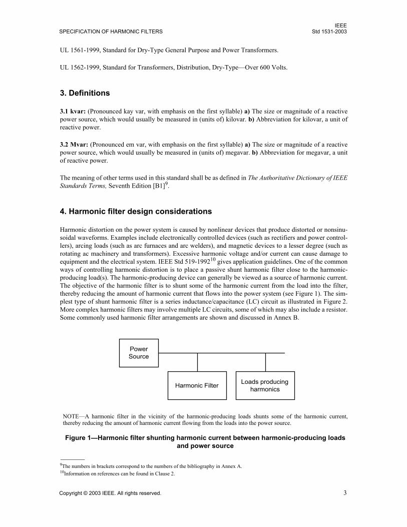
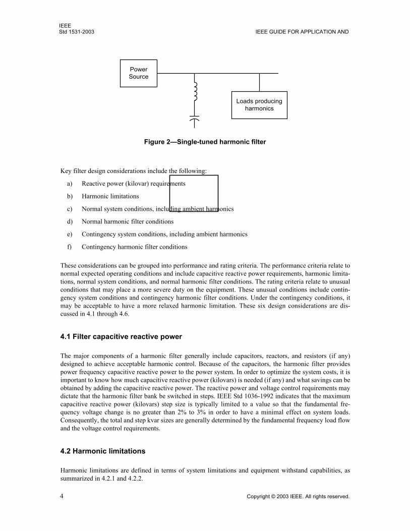
Harmonic distortion on the power system is caused by nonlinear devices that produce distorted or nonsinu-soidal waveforms. Examples include electronically controlled devices (such as rectifiers and power control-lers), arcing loads (such as arc furnaces and arc welders), and magnetic devices to a lesser degree (such asrotating ac machinery and transformers). Excessive harmonic voltage and/or current can cause damage toequipment and the electrical system. IEEE Std 519-199210 gives application guidelines. One of the commonways of controlling harmonic distortion is to place a passive shunt harmonic filter close to the harmonic-producing load(s). The harmonic-producing device can generally be viewed as a source of harmonic current.The objective of the harmonic filter is to shunt some of the harmonic current from the load into the filter,thereby reducing the amount of harmonic current that flows into the power system (see Figure 1). The sim-plest type of shunt harmonic filter is a series inductance/capacitance (LC) circuit as illustrated in Figure 2.More complex harmonic filters may involve multiple LC circuits, some of which may also include a resistor.Some commonly used harmonic filter arrangements are shown and discussed in Annex B.
9The numbers in brackets correspond to the numbers of the bibliography in Annex A.10Information on references can be found in Clause 2.
NOTEA harmonic filter in the vicinity of the harmonic-producing loads shunts some of the harmonic current,thereby reducing the amount of harmonic current flowing from the loads into the power source.
Figure 1Harmonic filter shunting harmonic current between harmonic-producing loads and power source
Harmonic Filter Loads producingharmonics
PowerSource
IEEEStd 1531-2003 IEEE GUIDE FOR APPLICATION AND
4 Copyright © 2003 IEEE. All rights reserved.
Key filter design considerations include the following:
a) Reactive power (kilovar) requirements
b) Harmonic limitations
c) Normal system conditions, including ambient harmonics
d) Normal harmonic filter conditions
e) Contingency system conditions, including ambient harmonics
f) Contingency harmonic filter conditions
These considerations can be grouped into performance and rating criteria. The performance criteria relate tonormal expected operating conditions and include capacitive reactive power requirements, harmonic limita-tions, normal system conditions, and normal harmonic filter conditions. The rating criteria relate to unusualconditions that may place a more severe duty on the equipment. These unusual conditions include contin-gency system conditions and contingency harmonic filter conditions. Under the contingency conditions, itmay be acceptable to have a more relaxed harmonic limitation. These six design considerations are dis-cussed in 4.1 through 4.6.
4.1 Filter capacitive reactive power
The major components of a harmonic filter generally include capacitors, reactors, and resistors (if any)designed to achieve acceptable harmonic control. Because of the capacitors, the harmonic filter providespower frequency capacitive reactive power to the power system. In order to optimize the system costs, it isimportant to know how much capacitive reactive power (kilovars) is needed (if any) and what savings can beobtained by adding the capacitive reactive power. The reactive power and voltage control requirements maydictate that the harmonic filter bank be switched in steps. IEEE Std 1036-1992 indicates that the maximumcapacitive reactive power (kilovars) step size is typically limited to a value so that the fundamental fre-quency voltage change is no greater than 2% to 3% in order to have a minimal effect on system loads.Consequently, the total and step kvar sizes are generally determined by the fundamental frequency load flowand the voltage control requirements.
4.2 Harmonic limitations
Harmonic limitations are defined in terms of system limitations and equipment withstand capabilities, assummarized in 4.2.1 and 4.2.2.
Figure 2Single-tuned harmonic filter
Loads producingharmonics
PowerSource
IEEESPECIFICATION OF HARMONIC FILTERS Std 1531-2003
Copyright © 2003 IEEE. All rights reserved. 5
4.2.1 System limitations
System harmonic limitations are generally defined to ensure that equipment does not malfunction or fail dueto excessive harmonic distortion. System limitations are recommended in Clause 10 and Clause 11 of IEEEStd 519-1992.11 IEEE Std 519-1992 recommends that the total voltage distortion at the point of commoncoupling to the utility be limited to 5% or less, depending upon the system voltage level and other factors;and 8% or less for most user busses at less than 1 kV. The total demand current distortion at the point ofcommon coupling to the utility is limited to the range of 2.5% to 20%, depending upon the size of the cus-tomers harmonic-producing load and other factors. (See IEEE Std 519-1992 for details.) The document alsogives higher limits for conditions lasting less than 1 hour.
4.2.2 Equipment withstand capabilities
Some of the withstand capabilities that are described in existing equipment standards are summarized in thissubclause.
When transformers are operating at rated load, the total harmonic current distortion should be limited to 5%as defined in IEEE Std C57.12.00-2000 and IEEE Std C57.12.01-1998.12 IEEE Std C57.110-1998 definesthe method for derating transformers when supplying nonsinusoidal loads. UL 1561-1999 and UL 1562-1999 define the transformer K-rating that is intended for use in high harmonic environments.
IEEE Std 18-200213 states that [c]apacitors are intended to be operated at or below their rated voltage.Capacitors shall be capable of continuous operation under contingency system and bank conditions providedthat none of the following limitations are exceeded:
a) 110% of rated rms [root-mean-square] voltageb) 120% of rated peak voltage, i.e., peak voltage not exceeding 1.2 x (square root of two) x rated rms
voltage, including harmonics, but excluding transientsc) 135% of nominal rms current based on rated kvar and rated voltaged) 135% of rated kvar
Additional application guidelines for capacitors are given in IEEE Std 1036-1992. It should be noted thatcapacitor fuses should be rated for the voltage and current, including harmonics, in a filter application.
The limitation to 135% of rated kvar in IEEE Std 18-2002 is based on dielectric heating at fundamental fre-quency and is based on the thermal stability test in that standard. The 135% limit in IEEE Std 18-2002 isbased on a maximum operating voltage of 110% of rated voltage and a maximum capacitance tolerance of+15% (the maximum allowable tolerance at the time the 135% limit was set). (1.12 × , thus135%.)
The total dielectric heating in a capacitor is a function of the force between the electrodes, the capacitance ofthe dielectric, and the number of force reversals per second.
The force is the result of the attraction of the positive and negative charges on the electrodes. The magnitudeof the charge Q on each of the electrodes is proportional to the voltage difference V between the electrodes.The force is proportional to the product of the charge magnitudes. Because the positive and negative chargesare equal to each other and are proportional to the applied voltage, the force (and losses) varies as the squareof the applied voltage.
11This information is from the referenced standard(s) and does not transplant these limits to this guide. See the first paragraph ofClause 2.12See footnote 11.13This quotation is from the referenced standard(s) and does not transplant these limits to this guide.
1.15 1.35≈
IEEEStd 1531-2003 IEEE GUIDE FOR APPLICATION AND
6 Copyright © 2003 IEEE. All rights reserved.
The total dielectric heating varies linearly with the capacitance of the dielectric. Changes in capacitance dueto change in area of the dielectric, thickness of the dielectric, and changes in the dielectric constant due tosmall materials variations all affect the total heating linearly.
The dc dielectric losses and resulting heating in a high voltage power capacitor are very small. The dielectriclosses are dominated by ac losses. Each time the force is reversed there is an amount of loss. The ac lossesare linear function of the applied frequency.
Therefore, for a single frequency, the dielectric losses are proportional to the square of the applied voltage,the capacitance, and the frequency, as shown in Equation (1):
(1)
Note that, for a capacitor, the reactive power Q is
(2)
(3)
(4)
Note the similarity in the expressions for dielectric loss and Q. For a single frequency, the dielectric heatingin the capacitor is proportional to the reactive power (measured in kilovars).
For a capacitor in a filter, there are multiple frequencies generating the dielectric heating. For filter applica-tions where (1) there is no significant dc voltage present, (2) the harmonic voltages across the capacitor aresmaller than the fundamental frequency voltage, and (3) the highest significant frequency is less than about1 kHz, the dielectric heating will be within the 135% limit if
(5)
or
(6)
wheref is the rated frequency of the capacitor and system (Hz),C is the actual capacitance of the capacitor (F),h is the harmonic order, for all significant harmonics including the fundamental (h = 1),V(h) is the capacitor voltage (rms) at the h harmonic (kV),I(h) is the capacitor current (rms) at the h harmonic (A), Qrated is the capacitor rated reactive power (kvar).
The inequality in Equation (6) is the one normally used to determine whether the dielectric heating is accept-able. While dc losses in a capacitor are small, the presence of dc voltage can increase the maximum chargeand significantly increase the ac losses. That increase is not reflected in the above inequalities, limiting theuse of these inequalities to applications where no significant dc voltage is present.
Higher frequency currents may result in eddy current or induced losses in addition to the dielectric losses.Where the harmonic currents are smaller than the fundamental current, the error caused by ignoring these
Dielectric Loss f CV2∝
Q V( ) I( )=
V( ) 2π f CV( )=
2π f C V( )2=
2000 π f C hV h( )2( )h∑ 1.35 Qrated≤
V h( )I h( )( )h∑ 1.35 Qrated≤
IEEESPECIFICATION OF HARMONIC FILTERS Std 1531-2003
Copyright © 2003 IEEE. All rights reserved. 7
losses is negligible. Where the harmonic currents are larger or there are significant harmonic currents above1 kHz, higher frequency capacitor equipment designs, which are beyond the scope of this guide, may berequired.
Proposed derating curves for harmonic voltages for constant speed motors are given in various references(see IEEE Task Force [B3] and Rice [B6]). Typically, these curves indicate that the derating of the motoroccurs for voltage distortions greater than 5%. For a typical distribution of harmonics, significant derating ofthe motor begins at about 8% total harmonic distortion (see IEEE P519.1/D8b14).
4.3 Normal system conditions
The normal system operating conditions are generally evaluated to assure that the harmonic filter design willmeet specific reactive power (kilovars) and harmonic performance requirements for these conditions. Thesenormal system operating conditions include the following:
a) All harmonic voltages and currents, including1) Characteristic harmonics of all expected loads.2) Uncharacteristic harmonics. Frequencies that are not theoretically characteristic of a perfectly
operating device may sometimes occur. (These uncharacteristic harmonic frequencies mayinclude even harmonics, triplen harmonics, and harmonics that are not integral multiples of thepower system frequency.) Analysis, experience, and field measurements will often help toquantify these values.
3) Background and future harmonic loads. Harmonics generated by other loads near the proposedload location will affect the harmonic current in the harmonic filter. In addition, some futureharmonic generating loads should be anticipated to reduce the probability of overloading theharmonic filter.
b) System voltage variation. Overvoltages to +5% are typically considered for normal load conditionsand +10% for unloaded system conditions. Undervoltage conditions are generally not critical forharmonic filter design, unless voltage is lost completely. In that case, the harmonic filters should bedisconnected from the system immediately until the system is restored to normal conditions.
c) System frequency variation. On the interconnected power system, frequency variations beyond± 0.1 Hz are rare. Larger frequency variations may occur when the system is fed from a local gener-ator. They can affect the duty of the harmonic filter and can also have a profound impact on theoverall harmonic performance of the system.
d) Power system configurations. Possible variations in the power system configuration that may affectthe filter should be evaluated. For example, in industrial power systems, changes in the supply trans-former and reconfigurations of the medium voltage feeders have the largest effect on the systemimpedance. Changes in the source power system (e.g., generation, transmission/distribution, trans-former changes) may also have a significant impact. These evaluations should include a realisticrepresentation of the system and its componentsgenerators, transformers (with proper windingconnections), lines (with conductor skin effect and capacitive charging), capacitors, reactors, and allsources of harmonics electrically close to the proposed filter site.
e) Loading conditions. Variations in the system load, as it affects the harmonic filter design, should beconsidered. Conditions to be considered include variations in the harmonic-producing loads, in thestatus of ac motors, and in the status of system capacitor banks and other harmonic filters. Linear(resistive) loads also should be included as they help to dampen harmonic resonant peaks.
f) System voltage unbalance. System unbalance can result in increased harmonic injections fromdistortion-producing equipment, particularly triplen harmonics, and facilitate their propagation onthe system.
14Numbers preceded by P are IEEE authorized standards projects that were not approved by the IEEE-SA Standards Board at the timethis publication went to press. For informaiton about obtaining drafts, contact the IEEE.
IEEEStd 1531-2003 IEEE GUIDE FOR APPLICATION AND
8 Copyright © 2003 IEEE. All rights reserved.
4.4 Normal harmonic filter conditions
Filters are seldom tuned to their exact calculated values. It is necessary to allow for the following parametervariations when evaluating the performance of the harmonic filters:
a) Component tolerances. Manufacturing tolerances must be considered for the inductance, capaci-tance, and resistance.
b) Ambient temperature variations. Capacitance and resistance both vary with temperature. The appro-priate temperature range depends upon the location. Capacitance variation with temperature is typi-cally in the range of 0.4% to 0.8% decrease per 10 °C increase in temperature.
c) Capacitor element or unit failures. Capacitor failures will result in a change in the harmonic filtertuning and may result in overvoltage on some parts of the capacitor bank. Larger harmonic filtersmay continue to give acceptable performance with a limited number of failed capacitor elements orunits. However, for smaller harmonic filters, the failure of one capacitor element or unit can cause arelatively large change and require the harmonic filter to be immediately disconnected.
4.5 Contingency system conditions
The contingency system operating conditions are generally evaluated to assure that the harmonic filterdesign will be rated adequately to handle these conditions although the normal system distortion limits maybe exceeded. These include the following:
a) Switching. The switching of harmonic filters or other system components may result in significantovervoltage duties for the harmonic filter components.The energization of large transformers can result in severe dynamic overvoltages on harmonic filtercomponents. When several single-tuned harmonic filters are energized simultaneously, the transient overvoltagescan be very severe on small harmonic filters tuned to relatively low frequencies.When multiple-tuned steps are switched individually, it may be necessary to assure that they areswitched on and off in the proper order so that an undesirable parallel resonance does not occur.When switching harmonic filters, it is important that an adequate delay time be maintained betweenan open and a subsequent close. This delay allows time for the trapped charge on the capacitors todecay so that the resultant energizing transient voltages are not excessive. A delay time of 5 min isused with high-voltage capacitors (rated over 1000 V, where IEEE Std 18-2002 requires a dischargeto 50 V in 5 min), and 1 min for low-voltage capacitors (rated at 1000 V or less, where IEEE Std 18-2002 requires a discharge to 50 V in 1 min). Shorter time delays may be acceptable if a modestincrease in the energizing transient is acceptable. See 5.2.1 and 6.4. Where very short delays are required, discharge devices to rapidly discharge the capacitors may beused. Switching devices with insertion resistors or reactors, or switching devices designed to closewith near-zero voltage across the open contacts, may also be used to control system transientvoltages.
b) Application of filters tuned to the same frequency. When harmonic filters are applied at the samelocation and are tuned to the same frequency, care must be taken to assure that there is acceptablesharing of the harmonic currents among the harmonic filters. This current sharing is a function of thedifferences in the impedances of the harmonic filters.
c) System frequency variation. Frequency variations greater than the frequency variations for the nor-mal system conditions are generally considered.
d) Power system configurations. Single and double contingency conditions, which are more severethan the normal operating conditions, are evaluated. Sometimes it may be desirable that these condi-tions also meet the harmonic distortion criteria that were considered for normal operating condi-tions. Changes in system configuration (including connection/outage of harmonic filters) often
IEEESPECIFICATION OF HARMONIC FILTERS Std 1531-2003
Copyright © 2003 IEEE. All rights reserved. 9
result in significant shifts of harmonic resonant peaks, thus affecting the duties and design of multi-ple harmonic filter installations.
e) Characteristic and uncharacteristic harmonics. Higher values than the values used to evaluate per-formance are typically used for the rating of the equipment.
f) Unknown harmonic sources. It is best to identify all of the significant harmonic sources on thepower system. Sometimes such identification may be difficult and carefully conducted and docu-mented field measurements may be helpful in resolving this issue. It is often advisable to add a fac-tor to the calculated harmonic duties to account for unknown or future harmonic sources when ratingthe equipment.
4.6 Contingency harmonic filter conditions
When rating the harmonic filter components, the same factors that were given in 4.4 for normal harmonicfilter conditions (without any failure or abnormality in the harmonic filter) are typically used, but with widerranges. In addition, when multiple harmonic filters are applied at the same location, the outage of a completeharmonic filter is often considered in rating the filter components. In some applications, the outage of a sin-gle harmonic filter may require that the other harmonic filters be disconnected so that their ratings are notexceeded.
4.7 Harmonic filter locations
Harmonic filters may be located at individual devices or at a common bus that feeds many loads. They maybe located at low voltage (e.g., 480 V) or at higher voltages (e.g., 4.16 kV or 12.47 kV). The alternatives in agiven application should be evaluated based on meeting the acceptable harmonic voltages and currents andthe effect of the resulting harmonic load flows on the affected equipment and conductors (e.g., losses,heating).
4.8 Harmonic filter configurations
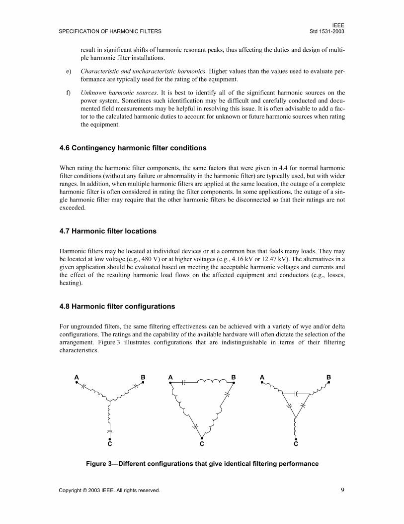
For ungrounded filters, the same filtering effectiveness can be achieved with a variety of wye and/or deltaconfigurations. The ratings and the capability of the available hardware will often dictate the selection of thearrangement. Figure 3 illustrates configurations that are indistinguishable in terms of their filteringcharacteristics.
Figure 3Different configurations that give identical filtering performance
A A AB B B
CCC
IEEEStd 1531-2003 IEEE GUIDE FOR APPLICATION AND
10 Copyright © 2003 IEEE. All rights reserved.
The schematic to be used and the relative positions of the components are generally dictated by constructionand/or protection considerations. The filters illustrated are all single-frequency harmonic filters, tuned forone frequency. A wide variety of schematics are also available for multiple-tuned harmonic filters.
4.9 Using existing capacitor banks
Occasionally, consideration will be given to converting an existing capacitor bank to a harmonic filtercapacitor bank. It is important to compare the unit ratings of the existing bank with the required ratings for aharmonic filter capacitor bank.
In addition to increased harmonic voltage stresses, the fundamental frequency component will also beincreased according to the equation for VC (1) as shown in Item c)1 in 6.3.1. Other issues, including reactivepower (kilovars) and current, as presented in this guide, must also be considered.
Usually the existing capacitor banks cannot be used in a harmonic filter unless the capacitor units were over-rated in the original installation.
5. Low-voltage shunt harmonic filters
This clause applies to harmonic filters installed at bus voltages up to and including 1 kV. The components,protection, and general design of low-voltage harmonic filters are discussed. The clause concludes with anapplication design example of multiple harmonic filters installed at a water treatment facility. Applicablecodes and standards are mentioned where appropriate.
5.1 Introduction
Application of harmonic filters at low voltage is required when any of the following conditions exists:a) Harmonic voltages appearing across the low-voltage distribution system result in voltage distortion
at a point of utilization that is incompatible with connected loads.b) Harmonic currents exceed specified limits.c) Harmonic currents exceed the thermal capability of distribution equipment.d) Power factor correction at the low-voltage bus is desired in a harmonic-rich environment.
Like conventional shunt capacitors, which are not a part of a harmonic filter, passive harmonic filtersimprove power factor ahead of the point of connection and thereby reduce the fundamental current, releasecapacity in the distribution system, and reduce losses. Unlike conventional shunt capacitors, which are not apart of a filter and can create an undesirable resonance and thus amplify harmonic currents, harmonic filterscontrol the resonant frequencies and shunt harmonic currents out of the system and thereby further reducelosses and improve voltage quality.
Both fundamental and harmonic components must be considered in selecting equipment ratings. Capacitorsand reactors should not operate above their nameplate ratings under normal conditions. Overload capabili-ties should be reserved for contingency operation only. A harmonic filter should be adequately protected sothat a severe overload condition does not result in equipment damage.
Harmonic filters may be installed at the load or an upstream bus. They may be fixed or switched. Harmonicfilters are typically single-tuned, series LC devices where the absorption spectrum will include more thanone harmonic. For example, a 5th harmonic filter may also absorb significant quantities of the 7th harmonic.However, the application requirements may dictate the use of multiple-tuned harmonic filters and/or high-pass sections.
IEEESPECIFICATION OF HARMONIC FILTERS Std 1531-2003
Copyright © 2003 IEEE. All rights reserved. 11
5.2 Technical specifications
General requirements for harmonic filter components and construction are give in 5.2.1 through 5.2.10.
5.2.1 Harmonic filter capacitors
Capacitors are generally rated for the system line-to-line voltage (e.g., 240 V, 480 V). However, in a har-monic filter application, they should be selected to withstand overvoltages and overcurrents caused by fun-damental and harmonic current flow through the series connected tuning.
IEEE Std 18-2002 requires shunt capacitors, under contingency conditions, to withstand continuous voltagesup to 110% of rated rms voltage and continuous currents up to 135% of nominal rms current based on ratedkvar and rated voltage. When applied in harmonic filters, the normal voltage and current may exceed theselevels even before system contingencies are considered. Consequently, capacitors selected for use in normalshunt capacitor applications may not be suitable for use in harmonic filters. Harmonic filter capacitorsshould be selected based on their expected duty under normal and contingency conditions. The capacitormanufacturer should be consulted when specifying capacitors for harmonic filter applications.
Capacitors should be manufactured in accordance with UL 810-1995. Capacitors should be protected by aUL-listed/recognized protective device. For capacitors that do not contain a UL-listed/recognized protectivedevice, the capacitors should be protected with external current limiting fuses or other external protectivedevices that are UL-listed. Capacitor cells connected with a wiring harness may also be protected with UL-listed current limiting fuses (even if they have internal pressure sensitive interrupters) to protect in the eventof a failure of external resistors, bushings, or connecting wires.
IEEE Std 18-200215 specifies that the terminal-to-case test for the internal insulation of indoor capacitorsshould be performed at 3 kV rms (capacitors rated 300 V or less) or 5 kV rms (capacitors rated 301 V to1199 V) for 10 s. The terminal-to-terminal test should be 10 s at 2 × rated rms voltage (ac test) or 4.3 × ratedrms voltage (dc test).
Each capacitor rated 600 V or less must be provided with a discharge resistor(s) to reduce the residual volt-age from peak of rated to less than 50 V within 1 min of de-energization (5 min for capacitor units ratedhigher than 600 V) to meet the requirements of IEEE Std 18-2002 and Article 460-6 of NFPA 70-2002(National Electrical Code®).
5.2.2 Harmonic filter reactors
5.2.2.1 General construction
Harmonic filter reactors for low-voltage applications are typically dry-type iron-core. No existing standardaddresses harmonic filter reactors, but most manufacturers use IEEE Std C57.12.01-1998 as a guideline.
Cores are constructed from silicon sheet steel (such as M-6). The number 6 corresponds to the approximatepower loss per pound of steel at a magnetic flux density of 1.5 T, i.e., M-6 has a loss of 0.6 W/lb or1.5 W/kg. M-6 is the typical grade of silicon steel used, but both lower and higher grades of steel are avail-able. A manufacturer may choose to use a lower grade steel and either let the harmonic filter reactor operatewith a higher temperature rise or use more steel. Conversely, a higher grade of steel can be used and eitherthe harmonic filter reactor may operate with a lower temperature rise or the harmonic filter reactor could bemade smaller.
15This information is from the referenced standard(s) and does not transplant these limits to this guide. See the first paragraph ofClause 2.
IEEEStd 1531-2003 IEEE GUIDE FOR APPLICATION AND
12 Copyright © 2003 IEEE. All rights reserved.
The construction may be from individual pieces of cut strip stock or E-I laminations. To create a harmonicfilter reactor, it is necessary to have gaps in the core. These gaps are known as air gaps, but for physicalintegrity and rigidity the gaps are filled with hard insulation. This insulation will have permeability similarto air. These gaps can be distributed (many small gaps) or a single larger gap. A single gap will use E-I lam-inations whereas a distributed gap will be made up of individual cut strips. The E-I construction requires lesslabor and can be clamped and wedged better than a distributed gap core. However, the distributed gap corewill significantly reduce fringing. This reduction in fringing helps control the effective cross-sectional areaas well as stray fields that may result in localized heating of the coil. A C core may be used, but it will notoffer an advantage for harmonic filtering.
Reactor coils may be constructed from sheet conductor or magnet wire. Sheet conductor may be more eco-nomical and easier for construction, but reactors with significant harmonic currents can incur heating prob-lems. If not properly designed, sheet copper windings can become annealed due to large localized currentdensities. Sheet conductor windings should be used only on harmonic filter reactors that have a distributedgap well within the boundaries of the coil. Magnet wire, which is less susceptible to localized heating, iscommonly used for harmonic filter reactors. In some cases, it may be desirable to have parallel strands ofsmaller gauge magnet wire to reduce heating. Although using parallel strands of such wire significantlycomplicates winding construction, the increase in winding complexity can be justified because coil lossesmay be significantly reduced.
Clamping is also very important. If a reactor is not properly clamped, the harmonic current can cause lami-nations to vibrate. Lack of proper clamping could result in a loud audible noise and the breakdown of theinsulation coating on the laminations. Laminations are clamped with insulated through-bolts, or bolts that gothrough clamps, and are external to the laminations. Clamps that bridge air gaps must be of nonferrous con-struction. Such nonmagnetic clamps are used to avoid shunting the air gap with a magnetic path. Further-more, ferrous components need to be as far from air gaps as possible to prevent inductive heating of theferrous material. Coils are held in place with spacers and wedges. The harmonic filter reactor should be vac-uum impregnated, preferably vacuum-pressure impregnated with a suitable varnish. Impregnation, however,should not be relied upon as the only mechanical means of support.
5.2.2.2 Properties
The loss calculation should consider the total rms current, including both the fundamental and harmonic cur-rents, which flow through the harmonic filter reactor and harmonic filter capacitor combination. Harmonicfilter reactor losses consist of
Coil loss Core loss Gap loss
The current should be given as a harmonic spectrum so the manufacturer can calculate losses for each fre-quency. The rms current is calculated as the geometric sum of the fundamental and all harmonics. Coilpower losses should be determined at the expected operating temperature.
The total coil loss is calculated as shown in Equation (7):
(7)
whereI (h) is the current at the hth harmonic (A rms),h is the harmonic number h = 1, 2, ...,Peddy (h) is the eddy current loss at the hth harmonic and at the rated operating temperature (W),Pc is the total coil loss at the rated operating temperature (W),
Pc I h( )2Rac h( ) Peddy h( ) Pstray h( )+ +[ ]∑=
IEEESPECIFICATION OF HARMONIC FILTERS Std 1531-2003
Copyright © 2003 IEEE. All rights reserved. 13
Pstray (h) is the loss at the hth harmonic and the rated operating temperature (W),
Rac (h) is the conductor resistance at the hth harmonic and the rated operating temperature (Ω).
Core and gap power losses are greatly influenced by harmonic current frequencies and their amplitudes. Thecore and gap losses should be determined at the fundamental frequency and at each of the harmonic frequen-cies. The losses at each frequency should be numerically added to determine the total loss. The total corepower loss should be less than 40% of the coil power loss. Gap power losses are also a function of theharmonic frequencies and their amplitudes. The gap loss should be determined at the fundamental frequencyand at each of the harmonic frequencies. These losses should be numerically added to determine total gappower loss. The total gap power loss should be less than 20% of the coil loss.
Saturation is not typically a problem with low-voltage harmonic filter reactors.
The dc resistance of the harmonic filter reactor should be determined at 25 °C.
Inductance is determined by the number of turns, the core cross-sectional area, and the width of the air gap.
Using finite element analysis, the design can be optimized adjusting all these factors until the desired induc-tance, losses, and temperature rise are obtained. Once the harmonic filter reactor has been built, fine-tuningis typically done by adjusting the air gap. When the gap is adjusted on a three-phase harmonic filter reactor,it changes for all three phases. However, with a three-phase harmonic filter reactor, the fringing characteris-tics that will affect the flux density and inductance of each phase are different for the center leg from whatthey are for the outer legs. Such differences create a challenge because all three gaps should be the same fora three-phase core. Fringing effects are less significant with a distributed air gap. With single-phase har-monic filter reactors, each phase may be individually tuned and adjusted.
5.2.2.3 Testing
To assure proper tuning, inductance should be measured at rated current. Inductance of harmonic filter reac-tors should not be measured on an instrumentation bridge. Harmonic filter reactors are not field adjustable.
For low-voltage applications, harmonic filter reactors do not typically undergo a basic impulse insulationlevel (BIL) test. As a minimum, the insulation should have a low-frequency voltage test (Hi-Pot), phase-to-phase (three-phase harmonic filter reactors) and phase-to-ground. This test is typically on the order of 10times the rms voltage rating. IEEE Std C57.12.01-199816 suggests a test voltage of 4 kV rms on 480 V sys-tems. If a similar field test is to be performed, consult with the harmonic filter manufacturer on the values toexpect and the procedure to be used.
5.2.2.4 Protection
The primary cause of harmonic filter reactor failure is over-heating of the insulation system. Iron core har-monic filter reactors typically have a 180 °C to 220 °C rated insulation system. Normal overcurrent protec-tion is inadequate to properly protect the harmonic filter from overload. At least one phase of a harmonicfilter section should have a thermal cutout or thermistor imbedded near the hot spot, which will disconnectthe harmonic filter section when the hot spot temperature approaches 180 °C. The temperature of the hotspot is higher than any other location in the harmonic filter reactor winding.
5.2.3 Capacitor and reactor tolerances
Both harmonic filter reactors and harmonic filter capacitors have tolerances. However, when constructing aharmonic filter, the combination of these tolerances is more significant than individual tolerances.
16This information is from the referenced standard(s) and does not transplant these limits to this guide.
IEEEStd 1531-2003 IEEE GUIDE FOR APPLICATION AND
14 Copyright © 2003 IEEE. All rights reserved.
Capacitor tolerances typically permit capacitance to exceed the nominal value. Capacitor units built accord-ing to IEEE Std 18-2002 since 2002 have a manufacturing tolerance of 0% to +10% at 25 °C uniform caseand internal temperature. Older capacitors may have tolerances as high as 0% to +15% for the capacitanceof individual units. Because capacitors are mass-produced, the filter manufacturer typically has very littlecontrol on the capacitor value.
No standard presently exists for harmonic filter reactors, although IEEE Std C57.16-1996 is oftenreferenced.
An example of the effect of tolerances is shown in Equation (8).
(8)
whereftuned is the actual tuned frequency,fnominal is the specified tuned frequency,tr is the reactor tolerance (per unit),tc is the capacitor tolerance (per unit).
For a filter that has been specified for 4.7th harmonic tuning, the tuning point ranges have been calculatedusing Equation (8). In both cases the capacitor tolerance used are 0%/+15% with an expected value of +8%from nominal. The inductance range example shows a ± 2.5% tolerance with the target inductance at nomi-nal. This calculation results in a filter tuning range from the 4.33rd to the 4.76th and an expected value nearthe 4.52nd. A second example shows a 0%/+10% tolerance with the targeted inductance to be at 5% abovenominal. This calculation results in a tuning range from the 4.38th to the 4.95th and an expected value nearthe 4.64th harmonic. These results show the need to be aware of component tolerances.
Another concern in low-voltage applications is the feeder inductance from the filter unit to where it is con-nected to the power system. The inductance of reactors for these systems will be on the order of hundreds ofmicrohenries. It is not unusual for long cable inductance to be at least a few microhenries. This inductancecan significantly affect the tuned frequency of the filter. When determining what frequency a harmonic filterneeds to be tuned for, do not forget to allow for inductance of the feeder cable.
Because the manufacturer has more control over the reactor tolerance than the capacitor tolerance, it is rec-ommended that a range of acceptable tuning points for the assembly be provided (i.e., 4.33 to 4.76) insteadof tolerances for individual components.
5.2.4 Contactors
Contactors are often incorporated into a harmonic filter assembly to enable it to be switched on and off withthe filtered load, or as load levels vary in the case of a bus mounted filter. Contactors should be either IEC orNEMA rated, and UL-listed or CSA-certified. The contactor should be rated, considering both system nor-mal and contingency conditions, for the following:
a) Maximum system voltage b) Maximum continuous current (fundamental current and all harmonic currents) c) Number of switching operations (Frequent switching suggests a more conservative approach to siz-
ing contactors than the normal current criteria would dictate. Note that the inrush current experi-enced when capacitors are switched is limited by the series tuning reactor. Therefore, the contactorscan be sized using the manufacturers inductive switching rating.)
d) Capacitor switching duty
ftuned fnominal1
1 tr+( ) 1 tc+( )----------------------------------------
=
IEEESPECIFICATION OF HARMONIC FILTERS Std 1531-2003
Copyright © 2003 IEEE. All rights reserved. 15
5.2.5 Fuses
Each phase of each filter step should be protected by fuses. Fuses should be current limiting, rated for theavailable fault current at the fuse location. Fuses should be UL-listed Class J or T, CSA-rated HRC-1, orequivalent. The current rating of the fuses should be a minimum of two times the capacitor current calcu-lated from its rated reactive power and its rated voltage. The voltage rating of the fuses should be greaterthan or equal to the system voltage. Fuses internal to the capacitor should not be accepted as the primarymeans of filter protection. In a harmonic filter assembly containing more than one capacitor per reactor, asingle set of fuses, one per phase, should be provided. The current rating of the fuses should be at least equalthe total filter current including all harmonics, with margin (typically 35%) to cover contingency conditions.
Fuses should be located after the harmonic filter main lugs or main disconnect and before the contactor/reactor/capacitor assemblies.
In addition to fusing, some harmonic filters may be protected by devices that detect phase loss or thermaloverload and trip the step/unit off line. Such devices are not meant to replace fuses.
The fuses should be rated for the following conditions:a) Maximum system voltageb) Maximum continuous filter current, including fundamental and harmonicsc) Interrupting rating, equal to or greater than the available short-circuit current at the fuse locationd) Sized to limit the fault current to a level consistent with the capabilities of the harmonic filter
componentse) Sized to withstand inrush currents when the harmonic filter is energized
5.2.6 Circuit breakers
Circuit breakers may be used in place of fuses to provide the primary means of overcurrent protection (i.e.,thermal/magnetic trip). Alternately, circuit breakers or molded case switches may serve in addition to fusesto provide a primary means of disconnect (i.e., manual switch) or to provide overload (i.e., thermal trip) and/or short-circuit (i.e., magnetic trip) protection for the complete harmonic filter.
Circuit breakers should be rated for the following conditions:a) Maximum system voltageb) The harmonic filter current spectrum, including the fundamental and harmonics (Note that this cur-
rent spectrum should be determined based on the maximum system operating voltage and maximumpositive capacitor tolerance. The heating of the circuit breaker may be greater at higher frequenciesthan at the fundamental frequency because of eddy currents and the skin effect. It is not sufficient tospecify only the rms value of the circuit breaker current.)
c) Interrupting rating, equal to or greater than the available short-circuit current at the harmonic filterd) Sized to limit the fault current to a level consistent with the capabilities of the harmonic filter
components.e) Sized to have sufficient short-time current rating to withstand inrush currents when the harmonic fil-
ter is energizedf) The number and the frequency of switching operations
5.2.7 Connections
UL 508-1999 and UL 508A-2001 should be followed in the design and construction of harmonic filterbanks. The harmonic filter should be electrically connected to the three-phase bus through mechanical lugsor compression lugs. All code requirements regarding internal grounding of the enclosure must be followed.
IEEEStd 1531-2003 IEEE GUIDE FOR APPLICATION AND
16 Copyright © 2003 IEEE. All rights reserved.
It is important that mechanical connections to the electrical elements of the harmonic filter exhibit low elec-trical resistance and be mechanically secure. All distribution blocks, lugs, and terminal strips should utilizethreaded studs with lock nuts or screw compression type connections. Terminal lugs used on wires should bepressure crimped to the wires. Locking spade or ring terminal lugs are recommended for current-carryingconductors.
Power conductors should use insulation rated 90 °C or higher. Control and signal wire should be 600 V,90 °C rated, or multiple conductor double jacketed with 300 V 80 °C insulation (see UL 508-1999 and UL508A-2001).
5.2.8 High-pass harmonic filter resistor assemblies
Resistors are generally not required in single-tuned low-voltage harmonic filters. Typically, the value of theresistance in the filter consists primarily of the resistance in the inductor. The low resistance value enhancesthe harmonic filters effectiveness, while simultaneously minimizing power losses.
Resistor assemblies are required in high-pass harmonic filters. A high-pass harmonic filter has low imped-ance at frequencies higher than the tuned frequency. (It passes these higher frequencies.) The resistor inthis type of harmonic filter creates a low impedance at the rated frequency and nearly constant impedance athigher frequencies. This type of harmonic filter has been effectively used to attenuate commutation notchesand is sometimes applied in lieu of or in combination with single-tuned filters (see Ludbrook [B4]).
5.2.9 Enclosure and general construction
The enclosure should be NEMA rated, suitable for the intended environment. Where applicable, screened orlouvered openings should be provided for ventilation. Harmonic filter reactors add substantially to the heatgenerated inside the filter enclosure. Because the longevity of a capacitor is temperature critical, specialattention should be given to the ambient environment and cooling requirements for harmonic filter capacitorbanks. Systems are typically designed for a maximum ambient temperature of 40 °C.
Cooling may be provided by convection or fan forced as necessary to maintain the harmonic filter compo-nents below their rated operating temperatures. Extremely hot environments may require auxiliary cooling.Thermostatically controlled heaters should be provided to maintain proper component operating temperaturein cold climates and to prevent the formation of condensation on the components. An enclosure that isequipped with air filters should be maintained regularly to ensure proper airflow.
5.2.10 Integrated harmonic filter assembly
Harmonic filter equipment may be integrated as part of a freestanding switchboard or switchgear assembly.Components typically include iron core reactors, power capacitors, contactors, fuses, controller, and bus.Main switchgear generally consists of molded case or power circuit breakers, relays, meters, controls, andbus. The harmonic filter assembly may also be added to existing switchgear equipment.
5.3 General design considerations
Several factors influence the design and location of a harmonic filter. The primary motivation is the removalof harmonic currents produced by specific nonlinear loads, or power factor correction and harmonic attenu-ation of dispersed loads within the plant. Equipment that is overheating or malfunctioning will also be a fac-tor in deciding where to locate a harmonic filter. Refer to Wagner [B7] for more information regarding theeffects of harmonics. IEEE Std 519-1992 and utility requirements should provide a basis for performancecriteria.
IEEESPECIFICATION OF HARMONIC FILTERS Std 1531-2003
Copyright © 2003 IEEE. All rights reserved. 17
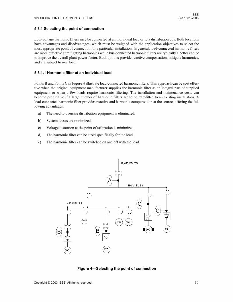
5.3.1 Selecting the point of connection
Low-voltage harmonic filters may be connected at an individual load or to a distribution bus. Both locationshave advantages and disadvantages, which must be weighed with the application objectives to select themost appropriate point of connection for a particular installation. In general, load-connected harmonic filtersare more effective at mitigating harmonics while bus-connected harmonic filters are typically a better choiceto improve the overall plant power factor. Both options provide reactive compensation, mitigate harmonics,and are subject to overload.
5.3.1.1 Harmonic filter at an individual load
Points B and Points C in Figure 4 illustrate load-connected harmonic filters. This approach can be cost effec-tive when the original equipment manufacturer supplies the harmonic filter as an integral part of suppliedequipment or when a few loads require harmonic filtering. The installation and maintenance costs canbecome prohibitive if a large number of harmonic filters are to be retrofitted to an existing installation. Aload-connected harmonic filter provides reactive and harmonic compensation at the source, offering the fol-lowing advantages:
a) The need to oversize distribution equipment is eliminated.
b) System losses are minimized.
c) Voltage distortion at the point of utilization is minimized.
d) The harmonic filter can be sized specifically for the load.
e) The harmonic filter can be switched on and off with the load.
Figure 4Selecting the point of connection
IEEEStd 1531-2003 IEEE GUIDE FOR APPLICATION AND
18 Copyright © 2003 IEEE. All rights reserved.
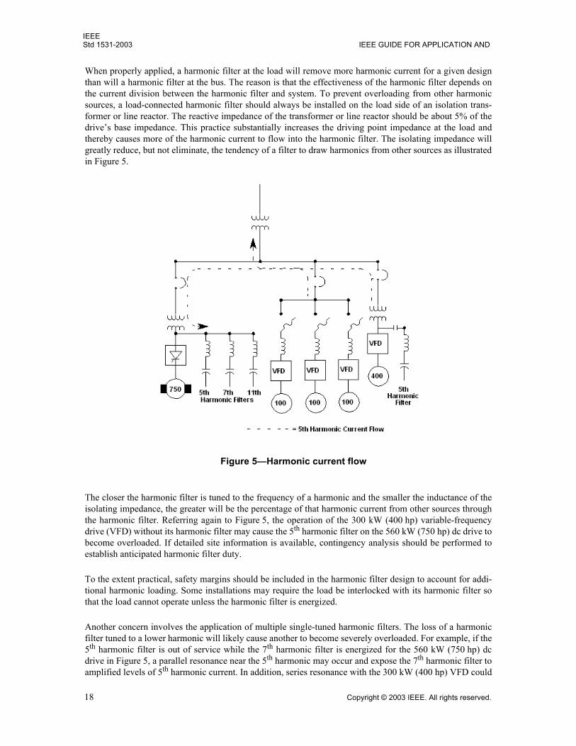
When properly applied, a harmonic filter at the load will remove more harmonic current for a given designthan will a harmonic filter at the bus. The reason is that the effectiveness of the harmonic filter depends onthe current division between the harmonic filter and system. To prevent overloading from other harmonicsources, a load-connected harmonic filter should always be installed on the load side of an isolation trans-former or line reactor. The reactive impedance of the transformer or line reactor should be about 5% of thedrives base impedance. This practice substantially increases the driving point impedance at the load andthereby causes more of the harmonic current to flow into the harmonic filter. The isolating impedance willgreatly reduce, but not eliminate, the tendency of a filter to draw harmonics from other sources as illustratedin Figure 5.
The closer the harmonic filter is tuned to the frequency of a harmonic and the smaller the inductance of theisolating impedance, the greater will be the percentage of that harmonic current from other sources throughthe harmonic filter. Referring again to Figure 5, the operation of the 300 kW (400 hp) variable-frequencydrive (VFD) without its harmonic filter may cause the 5th harmonic filter on the 560 kW (750 hp) dc drive tobecome overloaded. If detailed site information is available, contingency analysis should be performed toestablish anticipated harmonic filter duty.
To the extent practical, safety margins should be included in the harmonic filter design to account for addi-tional harmonic loading. Some installations may require the load be interlocked with its harmonic filter sothat the load cannot operate unless the harmonic filter is energized.
Another concern involves the application of multiple single-tuned harmonic filters. The loss of a harmonicfilter tuned to a lower harmonic will likely cause another to become severely overloaded. For example, if the5th harmonic filter is out of service while the 7th harmonic filter is energized for the 560 kW (750 hp) dcdrive in Figure 5, a parallel resonance near the 5th harmonic may occur and expose the 7th harmonic filter toamplified levels of 5th harmonic current. In addition, series resonance with the 300 kW (400 hp) VFD could
Figure 5Harmonic current flow
IEEESPECIFICATION OF HARMONIC FILTERS Std 1531-2003
Copyright © 2003 IEEE. All rights reserved. 19
expose the 7th harmonic filter to even higher levels of 5th harmonic current. Such a condition reinforces theneed for thermal overload protection for the harmonic filter.
5.3.1.2 Harmonic filter at a distribution bus
For certain applications, the most cost-effective solution for poor power factor, excessive voltage distortion,and IEEE Std 519-1992 violations is to install one or more larger harmonic filters at a distribution bus orbusses as indicated by A in Figure 4. Generally, an automatic harmonic filter bank will be installed on thesecondary of each main transformer in the plant requiring power factor and harmonic compensation. Place-ment of multiple banks on a common low-voltage system can create problems by changing network har-monic flows and thereby increase the potential for overloading some of the filter banks. Therefore, thispractice is not generally recommended. Where power factor correction is most important, systems tuned tothe 4.2nd harmonic or below can generally be safely applied in this manner. Parallel resonance at the 3rd har-monic must be carefully evaluated.
Caution must be exercised when a harmonic filter is electrically close to the main and is tuned to the 4.7th
harmonic or higher. In this case, the potential exists to absorb large amounts of harmonic current from theutility distribution system. Harmonic filters should be designed assuming the distribution system will haveup to 3% voltage distortion at the harmonic nearest the tuning frequency per IEEE Std 519-1992. If the har-monic filter reactors are not equipped with taps, as is common with low-voltage filters, a good practice is toover-specify the thermal rating so that additional capacitance may be added to detune the filter in the event aharmonic overload occurs.
If altering the tuning results in unacceptable filtering of in-plant harmonics, the utility can generally help toidentify methods for reducing the available harmonic current. Possible utility-side solutions include thefollowing:
Changing the size or status of capacitor banks to alter the impedance characteristics of the system Enforcing IEEE Std 519-1992 limits on customers with excessive harmonic injection Circuit reconfiguration to isolate harmonic injectors Medium-voltage harmonic filters
During lightly loaded conditions, harmonic filters that are fixed on the bus can produce an overvoltage con-dition. The maximum per-unit voltage rise caused by the harmonic filter can be estimated as approximatelyequal to the harmonic filter power system frequency current (i.e., fundamental current) divided by the sys-tem three-phase short-circuit current at the harmonic filter location (see IEEE Std 1036-1992). If overvolt-age is a concern, an automatically switched harmonic filter should be considered.
Switched harmonic filter(s) comprise a number of steps, each of which is an individually tuned harmonic fil-ter. Reactive current controllers (sometimes referred to as var controllers) that can switch steps in and outautomatically as system reactive current (i.e., power factor) changes are readily available. Other switchingalternatives include the use of current relays, time-of-day controllers, voltage controllers, or other sensingdevices. Switching times become more important as the harmonic filter is tuned closer to its rated frequency.Temporary duties should be evaluated with automatic harmonic filters to ensure steps do not overload beforeenough compensation is added. Steps should typically be switched in at 10 s to 15 s intervals. If the control-ler has the capability, the step removal interval should be greater than 1 min to avoid unnecessary seekingor hunting by the controller. Note that some controllers include algorithms to avoid seeking orhunting.
5.3.1.3 Combined load/bus approach
When harmonic sources constitute only part of a plant system load, harmonic filters connected at individualloads may leave the power factor at the bus lower than desired. A combination of the two methods leads toan acceptable result. Appropriate load-connected harmonic filters are selected for individual
IEEEStd 1531-2003 IEEE GUIDE FOR APPLICATION AND
20 Copyright © 2003 IEEE. All rights reserved.
harmonic-producing loads, and the remaining reactive power (kilovars) needed to achieve the desired powerfactor is added to the main as a detuned harmonic filter. (A detuned harmonic filter is a filter tuned to afrequency so that it will never become tuned with the source impedance at a frequency where there are sig-nificant harmonics. These filters are usually tuned below the 5th harmonic, e.g., at the 4.7th or 4.3rd
harmonic.)
Rarely can capacitors, which are not a part of a harmonic filter, be installed in the plant to supply the deficitcapacitive reactive power. Because only the lower harmonics are typically filtered, capacitors that are not apart of a filter may create an objectionable resonance at a higher harmonic frequency. Connecting capacitorsat individual motors is particularly risky because predicting all of the possible system conditions is practi-cally impossible. IEEE Std 141-1993 (IEEE Red Book) addresses in detail this concern and others related toconnecting capacitors at motor terminals.
5.3.2 Component selection
This subclause provides guidance in selecting harmonic filter capacitors and harmonic filter reactors toachieve the desired performance. For reliability, these and other harmonic filter components should beselected according to the specifications of 5.2. In harmonic filter design, the capacitors are chosen first basedon the required reactive power. The inductance of the harmonic filter reactor is then chosen to create thedesired tuning. In practice, the selection of harmonic filter components may require several iterationsbecause filter capacitors are typically voltage rated 10% to 25% higher than the system voltage for whichthey are designed, and the harmonic filter reactor absorbs some reactive power while raising the voltageacross the capacitor. Both factors can significantly alter the actual reactive compensation produced from thevalue stated on the capacitor nameplate. After this initial component selection, computer simulation shouldbe employed to evaluate the ability of the design to achieve the desired harmonic attenuation and verify theadequacy of component thermal and dielectric ratings.
5.3.2.1 Harmonic filter capacitor selection, method 1
This method of sizing the capacitors is more common because it is based on actual measured or predictedoperating data. Like sizing capacitors for a normal shunt capacitor application, the displacement power fac-tor is obtained from utility billing data, in-plant power monitoring systems, or temporary monitoring withportable power monitors. For a new system, the power factor must be calculated based on the expected oper-ating characteristics of the load(s). The capacitive reactive power that is required from the harmonic filter toreach the desired power factor is calculated. Standard power factor correction capacitor tables may be usedif desired.
5.3.2.2 Harmonic filter capacitor selection, method 2
When sizing harmonic filters for a converter, or group of converters, with a thyristor [e.g., a silicon control-ler rectifier (SCR)] bridge front end, the following method for capacitor selection can be used if the con-verter power factor is unknown. The capacitive reactive power in kilovars required to improve power factorto 0.900.95 is approximately 40% of the apparent power of the load in kilovolt-amperes. This relationshipis valid only if the load power varies proportionally with dc voltage. Larger uninterruptible power supply(UPS) systems often contain a thyristor front end and are an example of a load for which the power can varysignificantly without a change in the dc voltage. Such systems can incur high voltage at periods of light load(see 5.3.1.2) if the harmonic filter is sized based on this method.
If other than converter load is present, the system power factor may be less than optimal when applying thismethod. It is based on the observation that reactive and harmonic compensation for a thyristor rectifier isproportional to the size of the connected load. Empirical data, simulation, and extensive field testing haveverified this method. Shunt passive harmonic filters are not recommended for loads with a diode bridge frontend such as a pulse-width modulation (PWM) type of variable frequency drive. Such loads exhibit nearunity power factor throughout their operating range. The amount of capacitance that would be required for
IEEESPECIFICATION OF HARMONIC FILTERS Std 1531-2003
Copyright © 2003 IEEE. All rights reserved. 21
effective harmonic filtering will create a potential for high voltage at lower load levels. The magnitude ofthe voltage and possible adverse system impacts need to be reviewed. Alternate mitigating technologiessuch as line reactors, multiple pulse configurations, passive broadband harmonic filters, and active harmonicfilters may be more appropriate. IEEE P519.1/D8b provides additional information on these alternatives.
5.3.2.3 Harmonic filter reactor selection
After the capacitance is chosen, the reactor inductance is selected to tune the harmonic filter to the desiredfrequency according to
(9)
(10)
whereftuned is the tuned frequency of the harmonic filter (Hz),htuned is the harmonic to which the harmonic filter is tuned,L is the inductance in the harmonic filter circuit (H),C is the capacitance in the harmonic filter circuit (F).
Low-voltage harmonic filters are often tuned below the nominal frequency; e.g., a 5th harmonic filter may betuned to the 4.7th harmonic. The reasons for this practice include the following:
a) Capacitors with metalized film construction lose capacitance as they age, resulting in a gradualincrease in tuning frequency when used in harmonic filters. Using capacitor manufacturers agingtables, a harmonic filter tuned at 6% below its rated frequency will still exhibit acceptable tuning atthe end of its 20 yr life. (Nonmetalized electrode capacitors have fairly stable capacitance. Refer tothe manufacturers aging tables.)
b) Tuning a harmonic filter more sharply than required to attain the desired performance unnecessarilystresses the components and generally makes the harmonic filter more prone to overload from otherharmonic sources.
c) The manufacturing tolerance of the harmonic filter reactor may result in a tuning frequency higherthan nominal.
d) Operation of capacitor fuses on failed capacitor units or elements will result in an increase in tuningfrequency.
In some cases where displacement power factor improvement is desired and harmonic removal is secondary,capacitors are tuned 12% or more below their nominal frequency. (The nominal frequency is the integermultiple of the fundamental frequency that the filter is primarily intended to remove. When tuned in thisfashion, the resultant device is protected against harmonic overload. Such designs can be safely used withharmonic generating loads, but may not absorb enough harmonic current to enable compliance with speci-fied harmonic limits.
5.3.2.4 Computer analysis
As with any design activity, some form of simulation is necessary to verify a device will operate as intended.In order to produce an optimized harmonic filter design, it is essential to develop an accurate mathematicalmodel to describe the harmonic behavior of the system.
The following data are typically incorporated into the model:
ftuned1
2π LC------------------=
htunedftuned
power system frequency( )--------------------------------------------------------------- 1
2π power system frequency( ) LC----------------------------------------------------------------------------------= =
IEEEStd 1531-2003 IEEE GUIDE FOR APPLICATION AND
22 Copyright © 2003 IEEE. All rights reserved.
a) Fundamental and individual harmonic current magnitudes and phase angles for the relevant nonlin-ear loads
b) Source impedance data
c) Feeder impedance (reactance and resistance)
d) Transformer impedance characteristics, size, and winding configuration
e) Size and location of all capacitor banks on the system being modeled (Note that usually this infor-mation is limited to capacitors within the plant, although capacitors on the utility system and neigh-boring facilities can have an impact and should be included if enough information is available.)
f) Harmonic current spectrum of all nonlinear loads
g) Subtransient reactance of all rotating machines on the system being modeled
Field data collection; site monitoring; utility/energy company billing data; system short-circuit capability;drive size and type; motor size; UPS; battery; rectifier; furnace; lighting; telcom/data systems; generators;heating, ventilation, and air conditioning (HVAC); and cable/bus data, along with a single line of the powerdistribution system, should be reviewed prior to analysis input.
If information about the site is not available in sufficient detail to create a suitable model, conservativeassumptions should be made. Additional information regarding harmonic modeling and simulation can befound in IEEE Std 519-1992, IEEE Std 399-1997, and IEEE Catalog Number: 98TP125-0 [B2].
5.4 Case study
A large wastewater treatment plant was undergoing a major capacity expansion. Part of this expansionincluded the addition of six 150 kW (200 hp) dc adjustable-speed drives and three 225 kW (300 hp) dcdrives. Concerns about low power factor and high harmonic voltage distortion resulted in a requirement forharmonic filtering for the new drives.
The facility, shown in outline in Figure 6, was supplied power through two pairs of parallel 1500 kVA trans-formers, each pair with a separate utility feeder.
Two harmonic filter design schemes were considered. Placement of a large automatically switched harmonicfilter bank on each main feeder was first considered. With numerous possible combinations of transformerand generator feed and possible load transfer between buses, it was felt that this design would result inunnecessary control complexities. The final design placed a fixed filter at each of the new drives, withcontactors and controls to switch on and off with the drive. The harmonic filters were connected to thedrives on the load side of the integrated line reactors.
Harmonic filters were sized using the alternate method for selecting capacitors. Eighty kvar harmonic filterswere installed on each 150 kW (200 hp) drive, and 120 kvar filters were installed on each 225 kW (300 hp)drive. Harmonic filters were connected through built-in circuit breakers and protected from overheating withovertemperature sensors in the harmonic filter reactors.
Table 1 contains selected data from preliminary testing upon installation of a 120 kvar harmonic filter on a225 kW (300 hp) drive. Note that the drive was not operating under the same load for the two measurementconditions.
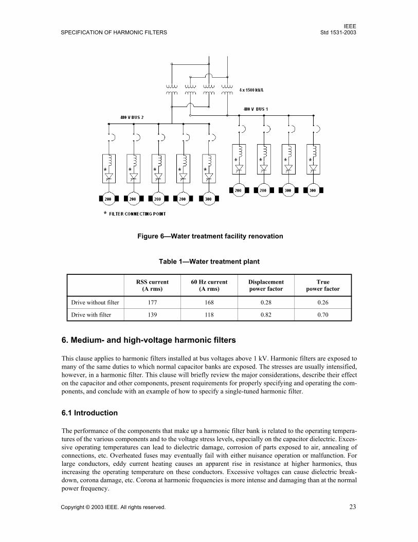
IEEESPECIFICATION OF HARMONIC FILTERS Std 1531-2003
Copyright © 2003 IEEE. All rights reserved. 23
6. Medium- and high-voltage harmonic filters
This clause applies to harmonic filters installed at bus voltages above 1 kV. Harmonic filters are exposed tomany of the same duties to which normal capacitor banks are exposed. The stresses are usually intensified,however, in a harmonic filter. This clause will briefly review the major considerations, describe their effecton the capacitor and other components, present requirements for properly specifying and operating the com-ponents, and conclude with an example of how to specify a single-tuned harmonic filter.
6.1 Introduction
The performance of the components that make up a harmonic filter bank is related to the operating tempera-tures of the various components and to the voltage stress levels, especially on the capacitor dielectric. Exces-sive operating temperatures can lead to dielectric damage, corrosion of parts exposed to air, annealing ofconnections, etc. Overheated fuses may eventually fail with either nuisance operation or malfunction. Forlarge conductors, eddy current heating causes an apparent rise in resistance at higher harmonics, thusincreasing the operating temperature on these conductors. Excessive voltages can cause dielectric break-down, corona damage, etc. Corona at harmonic frequencies is more intense and damaging than at the normalpower frequency.
Table 1Water treatment plant
RSS current(A rms)
60 Hz current(A rms)
Displacementpower factor
Truepower factor
Drive without filter 177 168 0.28 0.26
Drive with filter 139 118 0.82 0.70
Figure 6Water treatment facility renovation
IEEEStd 1531-2003 IEEE GUIDE FOR APPLICATION AND
24 Copyright © 2003 IEEE. All rights reserved.
Specifications provided to the equipment manufacturer must state the operating conditions in such a waythat temperatures can be predicted in the various components and that the dielectric stress and corona perfor-mance can be adequately predicted for design purposes. The performance specifications need to account fornormal continuous operation, background harmonics (from other harmonic generators in the vicinity), tem-porary harmonic overloads, regular energizing transients, various contingencies as they occur (e.g., trans-former energization, system faults, reclosing), and an estimate of future increases in harmonic loading fromthe addition of harmonic-generating loads in the vicinity.
Rather than specify the total rms current, it is much more appropriate to specify the harmonic current spec-trum from which the total heating and dielectric stress can be calculated. For example, a certain leg of the fil-ter may have an I1 fundamental, I2 of the 2nd harmonic, I3 of the 3rd harmonic, I5 of the 5th harmonic, etc.Dielectric stresses in capacitors can be determined by calculating the capacitor voltage at each harmonic. Bysumming the voltages, the worst-case peak voltage and dielectric stress can be calculated. Heating in har-monic filter reactors, resistors, fuses, etc., are also calculated for each frequency and summed for the totaleffect. Similar calculations are made for magnetic materials that may be used in the structure. The estimationof magnetic heating requires knowledge of the harmonic current spectrum.
Detailed specification requirements for each component of the harmonic filter and for the harmonic filtersoperation are provided in 6.3.
6.2 Harmonic overload considerations
Harmonic filters are generally designed to provide fundamental frequency reactive power compensation forinductive loads and to control harmonic currents and voltages. It is usually desirable to build the harmonicfilter with greater capability than is required for continuous duty of the identified harmonic loads. Other har-monics on the system will be drawn from the system and may lead to overloading. In addition, as loads areadded to the power system, harmonics may increase. The additional harmonics may increase the currentthrough the filter and cause an overloaded condition in the harmonic filter. The incremental cost of addingcapacity to a harmonic filter for unanticipated harmonic absorption is much lower than the average cost ofthe harmonic filter. A generous margin in specifying the harmonic duty is desirable. A minimum of 10%margin above the maximum anticipated duty from all sources is suggested.
Additional harmonic loading can come from nearby transformers. System events that cause transformer sat-uration (e.g., transformer energizing, clearing of nearby faults) will lead to a temporary surge in the filterharmonic current. If the harmonic filter remains connected to the system during and following a fault, har-monics generated by transformer saturation may lead to short-time overloading of the harmonic filter whenthe system is re-energized. If a harmonic filter is not going to be removed automatically during a system out-age, it is probably desirable to do a system study to determine the filter performance during this event. Sim-ilarly, nearby faults that do not cause a system outage but cause a voltage excursion may result in sometransformer saturation and temporary increasing of the loading of the harmonic filter. The duty imposed onthe harmonic filter by these transient conditions needs to be specified in a way that the proper componentsfor the filter can be selected.
Unfortunately, the effect of the transients is not easily defined because of the random variation of the har-monic magnitude during the period of the transient decay. For this reason, it is frequently desirable to pro-vide the designer with data (such as an oscillogram) from the study that gives the worst-case harmonicloading expected during this type of transient along with an identification of the magnitudes of the currentby harmonic order at the beginning or worst part of the transient.
Normally the switching of a single-tuned harmonic filter does not result in any unusual duty to the capacitorsor reactors over what would normally be expected in a shunt capacitor bank. However, for harmonic filtersthat are tuned for multiple frequencies, the transient duty on the components during routine capacitor bankswitching and system faults may be magnified and should be studied.
IEEESPECIFICATION OF HARMONIC FILTERS Std 1531-2003
Copyright © 2003 IEEE. All rights reserved. 25
For design purposes, it is desirable to provide the current magnitudes, by harmonic order, through each legof the harmonic filter both continuously and, as a function of time, for the worst-case short-term overloadingresulting from switching or a contingency. Resistors are sometimes used to dampen transients and reducethe short-time overloading.
6.3 Major component specifications
The major components of the harmonic filter bank generally include the capacitors, reactors, resistors (ifany), protective relaying, and the main switchgear. In specifying this type of equipment, the normal ratingsmust be specified with the additional requirements of harmonic current spectrums and tighter tolerances oncomponent parameters, specifically capacitance, inductance, and resistance. Harmonic currents result inhigher peak voltage, increased heat generation, and higher noise generation than most other power systemapplications. The applicable standards are noted below for each component with additional commentsrelated to the harmonic filter application as needed.
6.3.1 Harmonic filter capacitor assemblies
The capacitor should be designed so that operation during normal conditions should not result in voltages orreactive power that exceed 100% of the filter capacitor unit nameplate rating. IEEE Std 1036-1992 givescontinuous operating limits in excess of 100% nameplate rating. However, these limits are overload capabil-ities and should be reserved for contingency operation only.
IEEE Std 18-2002 gives the following limits for capacitor units:
Capacitors are intended to be operated at or below their rated voltage. Capacitors shall be capable of con-tinuous operation under contingency system and bank conditions provided that none of the following limita-tions are exceeded:
a) 110% of rated rms voltageb) 120% of rated peak voltage, i.e., peak voltage not exceeding 1.2 x (square root of two) x rated rms
voltage, including harmonics, but excluding transientsc) 135% of nominal rms current based on rated kvar and rated voltaged) 135% of rated kvar
Some of the key information related to capacitors is summarized as follows:a) Overload capabilities. The overload capabilities given above are generally used for contingency
conditions. These contingencies include system overvoltages, harmonic filter capacitor bank unbal-ance conditions, and other contingencies. Special consideration needs to be given to the harmonicfilter tuning during harmonic filter capacitor bank unbalance conditions (refer to 6.5.4) as the funda-mental and harmonic currents may increase significantly in all or in part of the harmonic filtercapacitor bank.
b) Specification items. Specifications for harmonic filter capacitor equipment for these applicationsshould include the following:1) The maximum system line-to-line operating voltage2) Power system fundamental frequency3) System BIL4) Total three-phase effective power frequency capacitive reactive power (megavars) at rated volt-
age, and the rated voltage of the filter5) Tuned frequency(ies) of the harmonic filter6) Installation type (e.g., indoor, outdoor, metal enclosed)
IEEEStd 1531-2003 IEEE GUIDE FOR APPLICATION AND
26 Copyright © 2003 IEEE. All rights reserved.
7) Environmental conditions [e.g., ambient temperature range, creepage requirements (industrialpollution), maximum wind velocity, ice loading, seismic requirements, altitude greater than1800 m above sea level]
8) Harmonic filter capacitor bank capacitance (microfarads) and tolerance9) The individual harmonic voltage peaks applied to the capacitors or individual harmonic cur-
rents through the capacitors, including the fundamental, during the various conditions in whichthe filter will operate (i.e., steady-state, normal, contingency)
10) Transient and dynamic voltage peaks for switching operations (e.g., switch restrike during har-monic filter deenergization, transformer energiziation)
11) The expected duty cycle or repetition rate and duration of the voltages and currents of Item 9and Item 10.
12) Harmonic filter capacitor bank configuration (e.g, grounded wye, ungrounded wye, or delta)c) Voltage rating. The rms voltage rating, Vr, of capacitors used in harmonic filter banks is specified as
the greater of Item 1, Item 2, or Item 3 as follows:1) Steady-state fundamental-frequency voltage plus the voltages due to the harmonic currents
through the capacitors. Such voltage should be calculated by the arithmetic sum of the powerfrequency and harmonic voltages as shown in Equation (11) [or Equation (12)].
(11)
whereVr is the rms voltage rating of the capacitor, h is the harmonic order,I(h) is the rms current through the capacitor at the given harmonic order,XC(h) is the capacitive reactance at the harmonic order.
or
(12)
if fundamental current through the capacitor is not specified.where
(13)
and where VC(1) is the maximum power frequency rms voltage across the capacitor,VS is the maximum system voltage across the capacitor, not including the voltage rise
across the tuning reactor,h is the tuned harmonic order of single-tuned filter (i.e., 4.3rd, 4.7th, 5th, 7th, and so
on).2) For transient events (generally less than 1/2 cycle of the power frequency, such as capacitor
bank switching, circuit breaker restrike, etc.), the voltage rating of the capacitor is calculated byEquation (14).
Vr I h( )XC h( )h 1=
∞
∑=
Vr VC 1( ) I h( )XC h( )h 2=
∞
∑+=
VC 1( ) VSh2
h2 1--------------
=
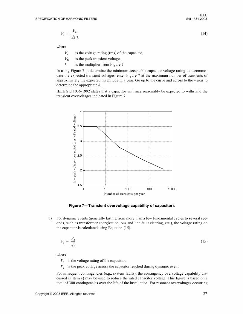
IEEESPECIFICATION OF HARMONIC FILTERS Std 1531-2003
Copyright © 2003 IEEE. All rights reserved. 27
(14)
whereVr is the voltage rating (rms) of the capacitor,Vtr is the peak transient voltage,k is the multiplier from Figure 7.
In using Figure 7 to determine the minimum acceptable capacitor voltage rating to accommo-date the expected transient voltages, enter Figure 7 at the maximum number of transients ofapproximately the expected magnitude in a year. Go up to the curve and across to the y axis todetermine the appropriate k.IEEE Std 1036-1992 states that a capacitor unit may reasonably be expected to withstand thetransient overvoltages indicated in Figure 7.
3) For dynamic events (generally lasting from more than a few fundamental cycles to several sec-onds, such as transformer energization, bus and line fault clearing, etc.), the voltage rating onthe capacitor is calculated using Equation (15).
(15)
whereVr is the voltage rating of the capacitor,Vd is the peak voltage across the capacitor reached during dynamic event.
For infrequent contingencies (e.g., system faults), the contingency overvoltage capability dis-cussed in Item e) may be used to reduce the rated capacitor voltage. This figure is based on atotal of 300 contingencies over the life of the installation. For resonant overvoltages occurring
VrVtr
2 k------------=
Figure 7Transient overvoltage capability of capacitors
1 10 100 1000 100001.5
2
2.5
3
3.5
4
Number of transients per year
k =
peak
vol
tage
(per
uni
tof c
rest
of r
ated
vol
tage
)
VrVd
2-------=
IEEEStd 1531-2003 IEEE GUIDE FOR APPLICATION AND
28 Copyright © 2003 IEEE. All rights reserved.
with some regularity in the operation of the harmonic filter, the voltage rating to endure reso-nant overvoltages calculated in Equation (15) is recommended.
The unit voltage ratings obtained from Equation (11) through Equation (15) may not result intypical capacitor unit ratings as shown in IEEE Std 18-2002. This result is not unusual. Manu-facturers can usually supply the required voltage ratings.
Occasionally, consideration will be given to converting an existing capacitor bank to a har-monic filter capacitor bank. It is important to compare the unit ratings of the existing bank withthe required ratings for a harmonic filter capacitor bank. In addition to increased harmonic volt-age stresses, the fundamental component will also be increased according to Equation (13).Other issues [including reactive power (kilovars) and current] as presented in this guide mustalso be considered.
d) Capacitance tolerance. The following capacitor parameters must be defined when designing a filterto achieve a specified tuning point:
Capacitance variation with temperature
Capacitance manufacturing tolerance
The effect of the capacitance tolerance on the performance of the harmonic filter must be evaluated.Capacitor units built according to IEEE Std 18-2002 since 2002 have a manufacturing toleranceranging from 0% to +10% at 25 °C uniform case and internal temperature. Older capacitors mayhave tolerances as high as 0% to +15% for the capacitance of individual units. While this rangemay be acceptable for shunt capacitor banks, it may be unacceptable for some harmonic filterapplications.
In harmonic filter designs, the capacitor manufacturer must select a tolerance for individual units sothat the filter capacitor bank capacitance tolerance is met. The capacitance tolerance of the individ-ual units should not exceed ± 5% of the rated unit capacitance. A reasonable tolerance for a fullcapacitor assembly is 4% (± 2%, or 0% +4%), measured at 25 °C. Tighter capacitance tolerancemay be achieved through consultation with the manufacturer.
Capacitance variation over the operating temperature range may be significant. Capacitor manufac-turers can usually provide the variation of capacitance with temperature.
e) Power frequency short-time overload capability. As given in IEEE Std 1036-1992,17 capacitor unitsmay reasonably be expected to have a short-time overload capability for 300 applications of powerfrequency overvoltage, without superimposed transients or harmonic content, of the magnitude andduration specified in the curve shown in Figure 8.
In using Figure 8, the overvoltage capability is for the capacitor unit, not the capacitor bank. Evalua-tion of capacitor unit overvoltage exposure should include allowance for any voltage unbalance inthe capacitor bank
The time axis of Figure 8 indicates the maximum duration for a single event. Capacitor unit damagetends to escalate during an event, so that damage is happening more rapidly at the end of the eventthan at the beginning. Two continuous seconds at 1.73 per unit is much more severe than two sepa-rate events of 1 s each, with a time in between to allow for localized cooling, absorption of coronagasses, etc. The curve should not be used to estimate the effect of contingency overvoltage eventsexceeding the maximum time indicated by the curve.
For event times shorter than indicated by the curve, the times of the individual events can be accu-mulated to estimate the effect of the shorter events. Ten 1.73 per-unit events of 0.1 s each (shorterthan the allowable 1 s limit of the curve) would create equal or less damage to the capacitor unit thanone 1.73 per-unit event of 1 s duration.
17This information is from the referenced standard(s) and does not transplant these limits to this guide. See the first paragraph ofClause 2
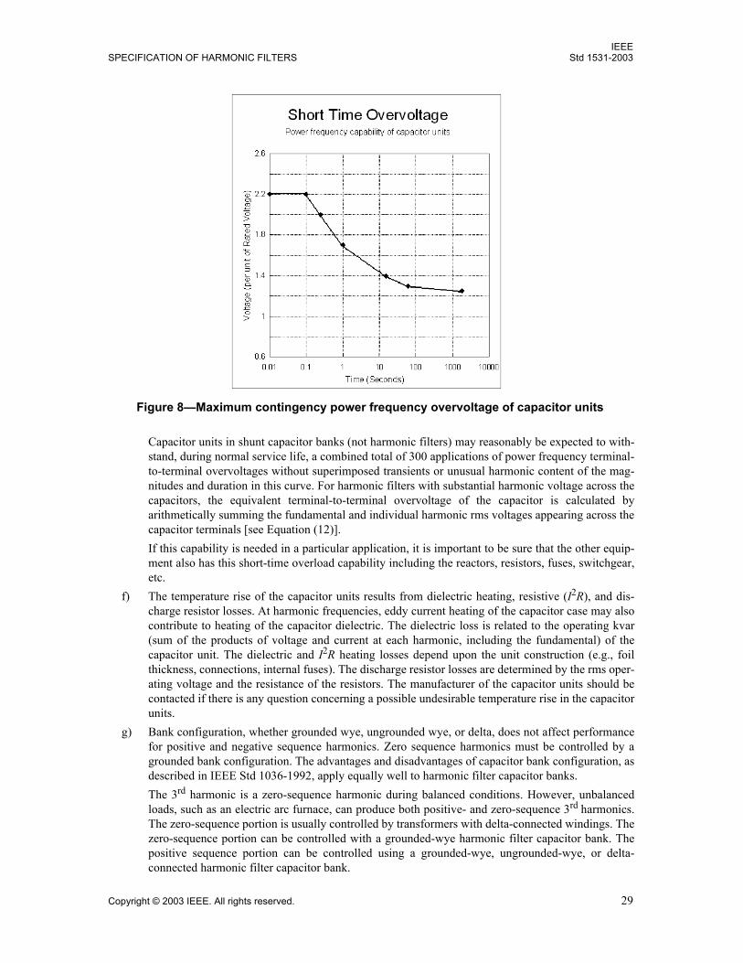
IEEESPECIFICATION OF HARMONIC FILTERS Std 1531-2003
Copyright © 2003 IEEE. All rights reserved. 29
Capacitor units in shunt capacitor banks (not harmonic filters) may reasonably be expected to with-stand, during normal service life, a combined total of 300 applications of power frequency terminal-to-terminal overvoltages without superimposed transients or unusual harmonic content of the mag-nitudes and duration in this curve. For harmonic filters with substantial harmonic voltage across thecapacitors, the equivalent terminal-to-terminal overvoltage of the capacitor is calculated byarithmetically summing the fundamental and individual harmonic rms voltages appearing across thecapacitor terminals [see Equation (12)].If this capability is needed in a particular application, it is important to be sure that the other equip-ment also has this short-time overload capability including the reactors, resistors, fuses, switchgear,etc.
f) The temperature rise of the capacitor units results from dielectric heating, resistive (I2R), and dis-charge resistor losses. At harmonic frequencies, eddy current heating of the capacitor case may alsocontribute to heating of the capacitor dielectric. The dielectric loss is related to the operating kvar(sum of the products of voltage and current at each harmonic, including the fundamental) of thecapacitor unit. The dielectric and I2R heating losses depend upon the unit construction (e.g., foilthickness, connections, internal fuses). The discharge resistor losses are determined by the rms oper-ating voltage and the resistance of the resistors. The manufacturer of the capacitor units should becontacted if there is any question concerning a possible undesirable temperature rise in the capacitorunits.
g) Bank configuration, whether grounded wye, ungrounded wye, or delta, does not affect performancefor positive and negative sequence harmonics. Zero sequence harmonics must be controlled by agrounded bank configuration. The advantages and disadvantages of capacitor bank configuration, asdescribed in IEEE Std 1036-1992, apply equally well to harmonic filter capacitor banks.The 3rd harmonic is a zero-sequence harmonic during balanced conditions. However, unbalancedloads, such as an electric arc furnace, can produce both positive- and zero-sequence 3rd harmonics.The zero-sequence portion is usually controlled by transformers with delta-connected windings. Thezero-sequence portion can be controlled with a grounded-wye harmonic filter capacitor bank. Thepositive sequence portion can be controlled using a grounded-wye, ungrounded-wye, or delta-connected harmonic filter capacitor bank.
Figure 8Maximum contingency power frequency overvoltage of capacitor units
IEEEStd 1531-2003 IEEE GUIDE FOR APPLICATION AND
30 Copyright © 2003 IEEE. All rights reserved.
6.3.2 Harmonic filter reactors
There is no existing ANSI or IEEE standard specifically related to harmonic filter reactors. The closest doc-ument is IEEE Std C57.16-1996. The referenced standard includes an annex that provides guidance forapplying dry-type air-core filter reactors. Filter reactors generally fall into three categories:
Dry-type, air-core reactors. Generally used in medium- and high-voltage applications. Dry-type, iron-core reactors. Generally used in low- and medium-voltage applications. Fluid-filled, iron-core reactors. Generally used in medium-voltage applications.
Some of the key information related to applying harmonic filter reactors that is different from applying otherseries connected reactors is summarized as follows:
a) Specification items. Specifications for harmonic filter reactors should include the following:1) The maximum system line-to-line operating voltage2) System fundamental frequency3) System BIL4) Tuned frequency of the filter (hertz)5) Installation type (e.g., indoor, outdoor, metal enclosed)6) Environmental conditions [e.g., ambient temperature range, creepage requirements (industrial
pollution), maximum wind velocity, ice loading, seismic requirements, altitude greater than1800 m above sea level]
7) Reactor inductance (millihenries) and inductance tolerance and whether taps are required8) Q at the tuned frequency, with its tolerance if critical (Note that Q is the ratio of reactance to
effective series resistance, X/R)9) Maximum short-circuit current and its duration through the reactor10) The individual harmonic currents through the reactor, including the fundamental, during the
various conditions in which the filter will operate (i.e., steady-state, normal, contingency) 11) Transient and dynamic voltage peaks for switching operations (e.g., switch restrike during filter
deenergization, transformer energization)12) The expected duty cycle or repetition rate and duration of the currents and voltages of Item 10
and Item 11.13) BIL rating across the coil and to ground (may be different)14) Preferred coil dimensions and mounting arrangements15) Audible noise limit (if applicable)
b) Three-phase, iron-core harmonic filter reactors. Three-phase (common-core) iron-core harmonicfilter reactors should be avoided in situations where the performance of the harmonic filter networkis critical. It is very difficult to adjust the inductance of one phase without affecting the inductanceof the other two phases. In addition, if the inductance of all three phases is set at the fundamental fre-quency, there is no guarantee that the inductance of all three phases will remain constant as the fre-quency is increased.
c) Inductance, inductance tolerance, and quality factor. The inductance and the quality factor, Q, forthe harmonic filter reactor should be specified at the resonant (tuned) frequency of the harmonic fil-ter network. The tolerance on the inductance should be selected to insure the proper performance ofthe harmonic filter network across the range of the tolerance. Inductance tolerance is usually avail-able as ± 3% or +0% to 6%. The tolerance on the quality factor, Q, is typically ± 20%.Reactor taps, if required, should also be specified. Taps are often included to provide final tuning inthe field and to accommodate changes in the capacitance of the harmonic filter capacitor bank. Har-monic filter capacitor banks are frequently built with the capacity for future expansion.
IEEESPECIFICATION OF HARMONIC FILTERS Std 1531-2003
Copyright © 2003 IEEE. All rights reserved. 31
d) Harmonic current spectrum. The harmonic current spectrum should be defined for both continuousand temporary/contingency conditions. Transient conditions should also be provided in applicationswhere the harmonic filter is exposed to frequent transients such as transformer energizing. The dutycycle or repetition rate of the transients and contingency operations should be specified. The har-monic current spectrum is required for the following reasons:1) To ensure that the core will not saturate and to determine the core and gap losses in the iron
core harmonic filter reactors.2) To assist the harmonic filter reactor designer in conductor selection in order to minimize resis-
tive, eddy and stray losses.The current specified for the fundamental frequency should account for variations in the linevoltage and the tolerance of the harmonic filter capacitance. The fundamental frequency shouldbe clearly stated also.
e) Voltage specifications. The (1) fundamental and harmonic voltages, (2) minimum required BILacross the coil, and (3) minimum required BILs from coil high-voltage and low-voltage terminals toground or core (iron-core harmonic filter reactors) must be specified.The rated steady-state voltage is calculated as the arithmetic sum of the fundamental and the har-monics, similar to the capacitor. See Equation (16).
(16)
whereVr is the rms voltage rating of the reactor,h is the harmonic order,I(h) is the rms current through the reactor at the given harmonic order (h),XR(h) is the inductive reactance at the given harmonic order.
The required contingency voltage capability is based on the same type of calculation using the con-tingency current instead of the continuous current.The coil-to-ground BIL will usually match the BIL of other equipment on the users system. If theharmonic filter reactor is located on the neutral side of the harmonic filter capacitor bank and oneterminal of the harmonic filter reactor is grounded, the BIL of the grounded terminal may bereduced.The terminal-to-terminal BIL across the coil will usually match the system BIL whether the har-monic filter reactor is located on the source side or the neutral side of the harmonic filter capacitorbank because the bulk of the lightning surge voltage will be across the harmonic filter reactor ratherthan the harmonic filter capacitor. Terminal-to-terminal BIL may be reduced if a surge arrester isconnected across the harmonic filter reactor terminals. The coil must then be adequately coordinatedwith the protective characteristics of the surge arrester (see IEEE Std C62.22-1997).The manufacturer should be made aware of frequent switching surge duties to which the harmonicfilter may be exposed. Frequent transformer switching on the same bus as the harmonic filter, forexample, may result in additional dielectric stresses to the insulation.
f) The maximum short-circuit current available to the harmonic filter reactor and the amount of timethe harmonic filter reactor must withstand this current must be specified. The value will varydepending upon the location of the harmonic filter reactor within the equipment. Fault currentthrough the harmonic filter reactor is minimized when the harmonic filter reactor is connected on theneutral side of the harmonic filter capacitor.
g) In configuring the harmonic filter, the mounting arrangement of the reactor and physical size limita-tions should be specified. The following items are noted:
Vr I h( )XR h( )h 1=
∞
∑=
IEEEStd 1531-2003 IEEE GUIDE FOR APPLICATION AND
32 Copyright © 2003 IEEE. All rights reserved.
1) For medium-voltage applications, the harmonic filter is generally connected in an ungrounded-wye configuration with the harmonic filter reactor located on the source side. The neutral con-nection is generally conveniently made within the harmonic filter capacitor equipment. Theharmonic filter reactor may limit the available fault current for a fault in the harmonic filtercapacitor bank if the reactor is located on the source side of the capacitor. However, iron-corereactors may not limit fault current if they saturate. Iron-core and air-core reactors located onthe neutral side of the harmonic filter capacitor will not decrease the available phase-to-phaseor phase-to-ground fault current level in the harmonic filter capacitor bank.
2) For high-voltage applications, the harmonic filter may be connected in a wye configurationwith the harmonic filter reactor located on the neutral side. This filter reactor location mayallow heavy harmonic filter reactors to be conveniently mounted at a lower elevation.For grounded-wye filters (effectively grounded systems only), this filter reactor location mayalso allow the BIL of the reactor to be less than the BIL of the system. For this application, anappropriately rated surge arrester should be placed across the harmonic filter reactor.
3) Air-core reactors must be mounted to prevent magnetic flux from producing excessive heatingin nearby ferromagnetic materials and/or affecting the harmonic filter tuning.
6.3.3 Harmonic filter resistor assemblies
The majority of passive harmonic filters are connected as high Q, single-tuned harmonic filters. Some appli-cations require the attenuation of more than one harmonic and require additional damping. A resistor oftensupplies the damping.
There is no existing ANSI or IEEE standard specifically related to harmonic filter resistors. The standardthat relates most to resistors in filter applications is IEEE Std 32-1972. Some of the additional considerationsfor use in harmonic filters are summarized:
a) Specification items. The specifications for harmonic filter resistor equipment should include thefollowing:1) The maximum system line-to-line operating voltage2) System fundamental frequency3) System BIL4) Installation type (e.g., indoor, outdoor, metal enclosed)5) Environmental conditions [e.g., ambient temperature range, creepage requirements (industrial
pollution), maximum wind velocity, ice loading, seismic requirements, altitude greater than1800 m above sea level]
6) Resistance (ohms) and resistance tolerance7) Maximum allowable inductance (if low inductance is required)8) Maximum allowable resistance variation with temperature (if resistance variation with temper-
ature is critical)9) The magnitude and duration of the maximum short-circuit current through the resistor10) The magnitude of the individual harmonic currents through the resistor, including the funda-
mental, during the various conditions in which the filter will operate (i.e., steady state, normal,contingency)
11) Transient and dynamic voltage peaks for switching operations (e.g., switch restrike during filterdeenergization, transformer energization)
12) The expected duty cycle or repetition rate and duration of the currents and voltages of Item 10and Item 11
13) Energy rating of the resistor (maximum adiabatic energy capability, optional for fluctuatingloads only)
IEEESPECIFICATION OF HARMONIC FILTERS Std 1531-2003
Copyright © 2003 IEEE. All rights reserved. 33
14) Minimum required BIL across the resistor, and minimum required BILs from resistor high volt-age and low voltage terminals to ground
15) Preferred dimensions and mounting arrangements
b) The resistor harmonic current spectrum must be defined for continuous and temporary/contingencyoperation. As with the reactors, this spectrum determines the heat/losses and vibration/noise consid-erations. Fundamental frequency losses may be substantial in some damped harmonic filter designs.
c) The maximum short-circuit requirement for the resistor is similar to the requirement presented forthe harmonic filter reactor in 6.3.2.
d) Some applications may require that the resistor has low series inductance.
e) Voltage requirements are similar to the requirements presented for the harmonic filter reactor in6.3.2.
f) The tolerance of the resistance with regards to frequency may need to be defined to ensure thedesired performance.
g) Mounting arrangements are similar to the harmonic filter reactor. Animal proofing, such as screensor enclosures, may be needed to prevent faults.
6.3.4 Switchgear
In general, the ANSI/IEEE Std C37 series includes guides and standards for switchgear and relays. IEEEStd C37.012-1979 provides guidance on applying high-voltage circuit breakers in switching capacitorbanks. ANSI C37.66-1969 provides guidance in applying oil switches for capacitor switching. InSection 460.24 of NFPA 70-2002 (National Electrical Code), there is also information on switching devicesfor capacitor switching. These documents generally recommend that the device be capable of switching acapacitive current and that the device be rated for at least 135% of the nominal current of the capacitor basedon rated reactive power and rated voltage. With high harmonic currents in a filter, the current rating needs tobe selected based on the expected continuous and contingency fundamental and harmonic currents.
Special consideration must be given to the specification of switching devices for harmonic filters. The fun-damental voltage rise across the reactor results in a higher recovery voltage on the switching device thanwhen switching a capacitor bank without tuning reactors. In addition, some switching devices may have dif-ficulty interrupting the high harmonic currents of a harmonic filter because of the higher rates of rise andpossible multiple zero crossings. The switching device manufacturer should be consulted for the applicationof switching harmonic filters. Refer to IEEE Std C37.04-1999, ANSI C37.06-2000, IEEE Std C37.012-1979, and ANSI C37.66-1969 for guidance with specification of these devices.
As compared with a shunt capacitor, the inrush and outrush currents are greatly reduced in a harmonic filterby the series tuning reactor. Adding a separate inrush or outrush limiting reactor would change the tuning ofthe filter and is not normally needed.
The specifications for switchgear used in harmonic filter applications should include the following:
a) The maximum system line-to-line operating voltage
b) The harmonic filter capacitor bank grounding (i.e., ungrounded, grounded, or impedance grounded).(If the bank is grounded through an impedance, state the ratings of the impedance.)
c) The grounding of the system (i.e., effectively grounded, impedance grounded, or ungrounded). (Ifthe system is grounded through an impedance, state the ratings of the impedance.)
d) System fundamental frequency
e) System BIL
f) Installation type (e.g., indoor, outdoor, metal enclosed)
IEEEStd 1531-2003 IEEE GUIDE FOR APPLICATION AND
34 Copyright © 2003 IEEE. All rights reserved.
g) Environmental conditions [e.g., ambient temperature range, creepage requirements (industrial pollu-tion), maximum wind velocity, ice loading, seismic requirements, altitude greater than 1800 mabove sea level]
h) Maximum short-circuit currentsymmetrical and asymmetrical, momentary and interrupting
i) The magnitude and duty cycle or repetition rate and duration of the individual harmonic currentsthrough the switchgear, including the fundamental, during the various conditions in which the har-monic filter will operate
j) Switchgear BIL
k) Duty cycle of switching operations (number and frequency)
l) Capacitor/harmonic filter switching duty, very low probability of restrike
m) The natural frequency of the harmonic filter tuning reactor. (This natural frequency affects the rateof rise of recovery voltage across the circuit breaker for a fault in the harmonic filter.)
None of the ANSI/IEEE Std C37 series addresses circuit breaker action in the presence of high harmoniccurrents. Interruption of current with higher rates of rise or higher rates of rise of recovery voltage may bemore difficult for some switches and circuit breakers. The switchgear supplier should be alerted to theapplication.
6.3.5 Conductors
Electrical conductors with large cross-sectional areas (e.g., buswork, cables, bushings) may be subjected toeddy current and skin effect heating from harmonic currents. The sizing of conductors based on rms currentalone may not be adequate. Conductor sizing should be based on the anticipated continuous and short-timeharmonic current duty, including the fundamental.
6.3.6 Grounding switch and key interlock
For servicing and maintaining the equipment, a three-phase and neutral grounding switch is often includedwhen using medium-voltage and high-voltage capacitors. In addition, key interlocks are included, which aretied to the main disconnecting device(s), the ground switch, and the enclosure doors if an enclosure is used.
6.3.7 Surge arresters
Surge arresters are used at a harmonic filter installation to prevent filter component failures or other systemequipment failures during switching surges, limit the risk of repetitive circuit breaker restrike, and limitlightning-induced overvoltages. The primary protective function of the arrester will determine its locationand rating.
Arresters connected line to ground at the harmonic filter terminals will provide general protection of substa-tion equipment from harmonic filter circuit breaker restrikes and lightning, but may not provide substantialreduction in the transients across the harmonic filter capacitor or the harmonic filter reactor. Arresters con-nected across the harmonic filter capacitors will provide capacitor protection; the surge arresters, however,are exposed to higher steady-state voltages and may be subject to higher surge discharge energies thanarresters located on the bus.
6.3.7.1 Specification items
The specifications for arresters used in harmonic filter applications should include the following:
a) The maximum system line-to-line operating voltage
b) System grounding (i.e., effectively grounded, impedance grounded, or ungrounded)
IEEESPECIFICATION OF HARMONIC FILTERS Std 1531-2003
Copyright © 2003 IEEE. All rights reserved. 35
c) Environmental conditions [e.g., ambient temperature range, creepage requirements (industrial pollu-tion), maximum wind velocity, ice loading, seismic requirements, altitude greater than 1800 mabove sea level]
d) Maximum available short-circuit current
e) Voltage rating or maximum continuous operating voltage (MCOV)
f) Class (e.g., distribution, intermediate, station)
g) Mounting arrangements
6.3.7.2 Surge arrester selection
Arresters located at the line terminals of a harmonic filter, where the harmonic voltage distortion is small,are applied in the same way as other arresters located on a power system. Arrester ratings are selected so thatthe device is able to withstand the MCOV, temporary overvoltage (TOV), and switching surge energyabsorption duties. A detailed description of the selection process is given in IEEE Std C62.22-1997.
For arresters located within a harmonic filter, where the voltage distortion may be substantial, the peakapplied voltage and harmonic heating should be considered in selecting the arrester rating. For the peak volt-age, the sum of the fundamental and all harmonic voltages at the arrester location (times the square root of 2)gives the maximum peak voltage expected. See Equation (17).
(17)
In order to avoid peaks of the voltage wave from being high enough above the peak of the arrester MCOV tocause turn on (conduction) and excessive heating, the arrester MCOV rating should be selected so that
(18)
The harmonic (dielectric) heating of the arrester is proportional to the order of the harmonic and the squareof the voltage of each harmonic (including the fundamental). In order that this heating not exceed the heat-ing of the same arrester applied at rated frequency only, the arrester MCOV rating should be selected so that
(19)
For continuous operation, the MCOV for arresters located in a harmonic filter should be based on the highervalue of Equation (18) and Equation (19). In addition to the continuous capability requirements for thearrester, there may be a contingency overvoltage requirement. If there is substantial short-time overvoltageacross the arrester, the short-time overvoltage capability of the arrester should be compared with theexpected exposure using peak voltages to determine the required MCOV to meet the short-time overvoltagerequirements of the application. Alternatively, if the arrester is modeled in a study of the overvoltage phe-nomena, the arrester energy may be compared with the energy capability of the arrester, as supplied by thesurge arrester manufacturer.
The surge protective level of the selected arrester must coordinate with the surge withstand level (e.g., BIL)of the filter component being protected. Usually a minimum margin of 15% for switching surges and 20%for lightning discharge is required between arrester protective level and equipment withstand level. Methodsof calculation of protective margins are contained in IEEE Std C62.22-1997.
Vpeak 2 V h( )h∑=
MCOV V h( )h∑≥
MCOV hV h( )2( )h∑≥
IEEEStd 1531-2003 IEEE GUIDE FOR APPLICATION AND
36 Copyright © 2003 IEEE. All rights reserved.
6.4 Harmonic filter switching control
The switching controls are similar to the controls used with standard capacitor banks. These controls are dis-cussed in IEEE Std 1036-1992. The key factors and differences for harmonic filters are summarized asfollows:
a) If the harmonic filters are switched, they are commonly controlled based on fundamental frequencyreactive power and voltage requirements with consideration for harmonics as required.
b) Although inrush and outrush currents need to be taken into account, they are typically lower in har-monic filter applications due to the presence of the harmonic filter reactor.
c) Undervoltage conditions are generally not critical for harmonic filter design, unless voltage is lostcompletely. In that case, the harmonic filters should generally be disconnected from the systemimmediately until the system is restored to normal conditions. Such timely disconnection avoidsdynamic overvoltage conditions that can occur when capacitors are energized with transformers.Dynamic overvoltages can also occur when large transformers are energized after the harmonic fil-ter is in service.
d) When a small (kilovar), low-frequency harmonic filter (such as a 3rd harmonic filter) is switchedwith a much larger higher frequency harmonic filter (such as a 5th harmonic filter), the transientvoltage in the 3rd harmonic filter may be excessive, resulting in harmonic filter reactor or harmonicfilter capacitor failures in that filter. This type of configuration should be evaluated carefully and theequipment rated as required.
Typical harmonic filter switching controls fall into the same categories as listed in the IEEE Std 1036-1992for standard capacitor installations. They include the following:
Voltage control
Current control
Reactive current control (sometimes referred to as a var control)
Time control
Temperature control
Switched harmonic filters using a voltage, current, or var control are usually switched based on the funda-mental voltage and reactive power requirements. Controllers or relays should incorporate proper filtering sothat the switching signal is based on the fundamental frequency voltage and current and not on other har-monic components.
The switching control or associated control circuitry is usually set with a 5 min delay between opening andclosing. This 5 min delay is based on the requirement of IEEE Std 18-2002 for capacitor units rated above600 V to have an internal device to discharge the residual voltage to 50 V within 5 min. This 5 min delayallows the trapped charge in each capacitor unit to decay to 50 V or less before the bus voltage is superim-posed upon it. (Note that capacitors built to standards other than IEEE Std 18-2002 may have differentdischarge times and require a different delay before re-energizing.)
Where less delay than 5 min is desired, allowing the trapped charge to decay to 10% of the crest of the ratedcapacitor unit voltage is usually acceptable. (A trapped change of 10% of the crest of rated voltage results ina 10% increase in inrush current and transient overvoltage.) The decay in voltage is exponential. The time inminutes required to reach 10% of the crest of rated voltage, Vrated, expressed in kilovolts (for capacitor unitsreaching 50 V in 5 min) is shown in Figure 9.
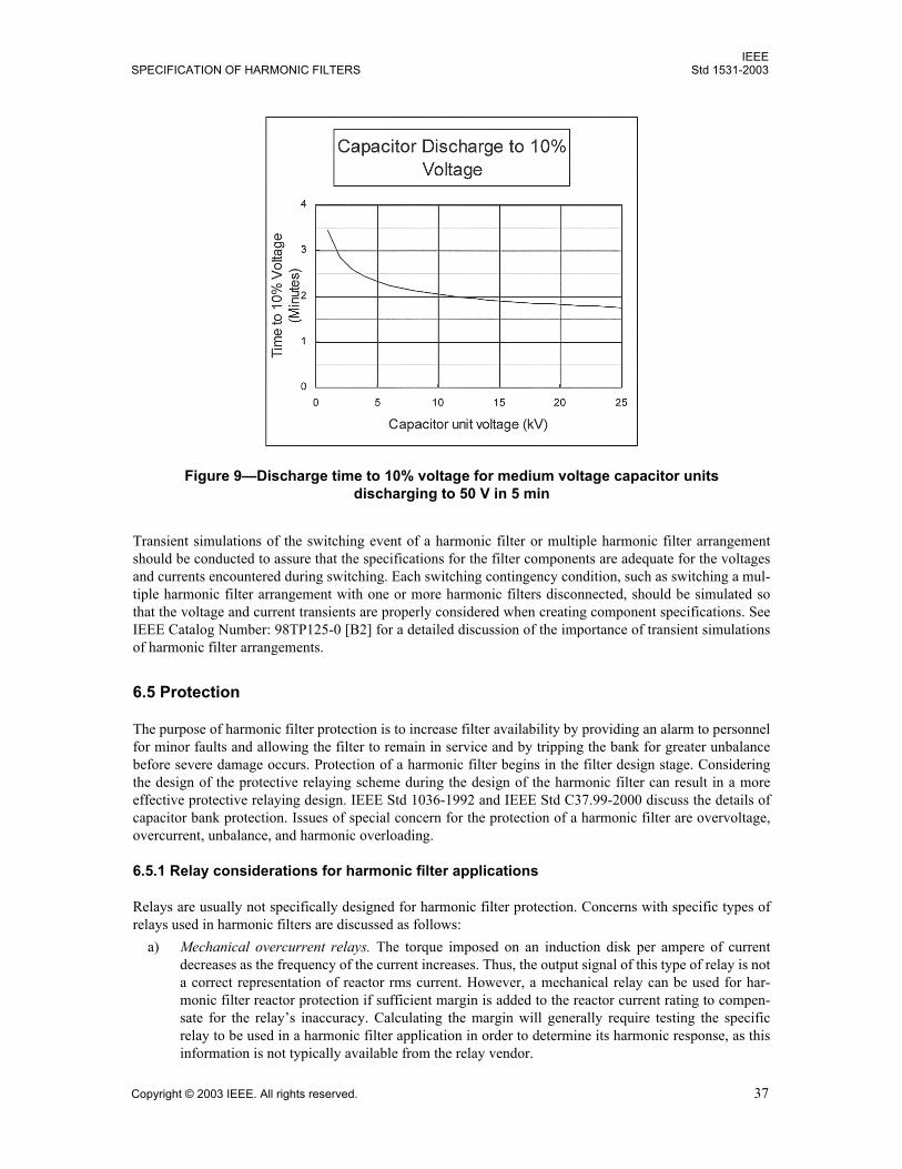
IEEESPECIFICATION OF HARMONIC FILTERS Std 1531-2003
Copyright © 2003 IEEE. All rights reserved. 37
Transient simulations of the switching event of a harmonic filter or multiple harmonic filter arrangementshould be conducted to assure that the specifications for the filter components are adequate for the voltagesand currents encountered during switching. Each switching contingency condition, such as switching a mul-tiple harmonic filter arrangement with one or more harmonic filters disconnected, should be simulated sothat the voltage and current transients are properly considered when creating component specifications. SeeIEEE Catalog Number: 98TP125-0 [B2] for a detailed discussion of the importance of transient simulationsof harmonic filter arrangements.
6.5 Protection
The purpose of harmonic filter protection is to increase filter availability by providing an alarm to personnelfor minor faults and allowing the filter to remain in service and by tripping the bank for greater unbalancebefore severe damage occurs. Protection of a harmonic filter begins in the filter design stage. Consideringthe design of the protective relaying scheme during the design of the harmonic filter can result in a moreeffective protective relaying design. IEEE Std 1036-1992 and IEEE Std C37.99-2000 discuss the details ofcapacitor bank protection. Issues of special concern for the protection of a harmonic filter are overvoltage,overcurrent, unbalance, and harmonic overloading.
6.5.1 Relay considerations for harmonic filter applications
Relays are usually not specifically designed for harmonic filter protection. Concerns with specific types ofrelays used in harmonic filters are discussed as follows:
a) Mechanical overcurrent relays. The torque imposed on an induction disk per ampere of currentdecreases as the frequency of the current increases. Thus, the output signal of this type of relay is nota correct representation of reactor rms current. However, a mechanical relay can be used for har-monic filter reactor protection if sufficient margin is added to the reactor current rating to compen-sate for the relays inaccuracy. Calculating the margin will generally require testing the specificrelay to be used in a harmonic filter application in order to determine its harmonic response, as thisinformation is not typically available from the relay vendor.
Figure 9Discharge time to 10% voltage for medium voltage capacitor units discharging to 50 V in 5 min
IEEEStd 1531-2003 IEEE GUIDE FOR APPLICATION AND
38 Copyright © 2003 IEEE. All rights reserved.
b) Solid-state relays. These relays have lower burden and may have better filtering than electrome-chanical relays.
c) Digital overcurrent relays. Most digital relays used for fault protection sample current at a rate thatis not sufficient to detect harmonics of interest. Any digital fault relay that is not certified to havetrue rms measuring capability should not be used in harmonic filter overload applications. Relaysthat respond to the fundamental current only may be preferred for unbalance protection.
d) Thermal relays. Thermal relays that sense temperature directly are effective for enclosed filterdesigns. These relays may sense the air temperature in the enclosure or the core surface temperatureof iron-core, harmonic filter reactors.Unenclosed medium-voltage or high-voltage air-core harmonic filter reactors cannot use direct tem-perature sensing relays because BIL considerations make imbedding sensors in the reactor windingsimpractical. Such applications can use relays in which the measured current heats a bimetal elementor other type of temperature sensor. However, commonly available relays of this type are designedfor motor overload protection and tend to be more inverse than desirable for harmonic filter pro-tection. To coordinate a motor relay in a harmonic filter subject to varying harmonic filter injection,the harmonic filter reactor current rating must be increased if the motor relay is to protect theharmonic filter reactor against a legitimate continuous overload without tripping during short-termperiods of high harmonic load that would not damage the reactor.
e) Programmable monitor/controller units. Programmable monitor/controller units usually calculatethe harmonic content of the sensed current correctly and provide digital outputs for relay operation.However, some programmable monitors are unsuitable for harmonic filter protection for subtle rea-sons such as lack of anti-aliasing filters on the monitor inputs.
6.5.2 Overvoltage protection
The key points of overvoltage protection of a harmonic filter are summarized as follows:a) Surge protection. Refer to 6.3.7 for a discussion of this topic.b) Bus overvoltage. The application of capacitors inherently results in a voltage rise at the fundamental
frequency. To protect the harmonic filter from abnormal system voltages that could damage filtercomponents, bus overvoltage relays or harmonic filter overcurrent relays designed to derive the trueovervoltage on the harmonic filer capacitors may be applied.
c) Harmonic overvoltage. Excessive harmonic currents may result in excessive harmonic filter capaci-tor voltages. Refer to 6.5.5 for further discussion of this topic.
d) Harmonic filter capacitor bank unbalance. Unbalances due to external or internal fuse operations orthe shorting of elements in a fuseless harmonic filter capacitor bank may result in excessive capaci-tor voltages in parts of the harmonic filter capacitor bank. Refer to 6.5.4 for further discussion of thistopic.
6.5.3 Overcurrent protection
The key points of overcurrent protection of a harmonic filter are summarized as follows:a) Harmonic overcurrent. Excessive harmonic currents may result in excessive harmonic filter capaci-
tor voltages and/or excessive heating in components such as harmonic filter reactors and harmonicfilter resistors. Refer to 6.5.5 for further discussion of this topic.
b) Harmonic filter capacitor fusing. Capacitor fuses are used to remove faulted capacitor units or ele-ments from service quickly enough to prevent case rupture or damage to other capacitor units or ele-ments. Power fuses are often used to provide major fault protection. Power fuses, individual externalcapacitor fuses, or internal fuses cannot provide harmonic filter capacitor overload protection. Fusesmust be sized, and possibly derated, to withstand, without damage, the harmonic currents and thetransient and dynamic overcurrents associated with application in a harmonic filter. In addition, thefuses must be rated for the power frequency and transient recovery voltages occurring in a shunt
IEEESPECIFICATION OF HARMONIC FILTERS Std 1531-2003
Copyright © 2003 IEEE. All rights reserved. 39
capacitor bank. Refer to IEEE Std C37.48-1997, IEEE Std 1036-1992, and IEEE Std C37.99-2000for more guidance about fuses for shunt capacitor bank applications.
c) Major fault protection. Major fault protection is generally provided by an external device such as apower fuse or switching device with associated relay circuits.
6.5.4 Harmonic filter unbalance and detuning protection
Usually the most critical function of the unbalance protection is to trip the harmonic filter capacitor bank offpromptly for a flashover or fault within the bank that may not be detected by the overcurrent protection.Such arcing faults within a capacitor bank frequently create very high transient overvoltages within thecapacitor bank and will lead to substantial damage if the capacitor bank is not promptly tripped (refer toIEEE Std C37.99-2000).
Unbalance and detuning protection (hereafter referred to as unbalance protection) refers to the detection ofand the protective actions taken for external or internal fuse operations or the shorting of elements of a fuse-less harmonic filter capacitor bank. Such fuse operations or shorting of elements changes the capacitance ofthe filter and may result in an increase in fundamental voltage applied to the remaining units/elements. Theeffects of this capacitance change and potential increase in fundamental voltage must be evaluated to deter-mine the appropriate protective action. Generally, the same methods of unbalance protection used for stan-dard capacitor banks are also used for harmonic filter capacitor banks. The key points of unbalanceprotection of a capacitor bank used in a harmonic filter are summarized as follows:
a) External or internal fuse operations or the shorting of elements of a fuseless harmonic filter capaci-tor bank changes the resonant frequency of the harmonic filter from its design point. Fuse operationsin a parallel connected harmonic filter capacitor bank result in a decrease in capacitance and a corre-sponding increase of the resonant frequency. There is also the possibility that the shorting of ele-ments of an externally fused capacitor without the fuse operation will result in an increase incapacitance and a corresponding decrease of the resonant frequency.The shorting of elements of a fuseless harmonic filter capacitor bank results in an increase in capac-itance and a corresponding decrease of the resonant frequency. Refer to 6.6 for a discussion of theconsequences of filter detuning.In specifying the unbalance protection requirements for a capacitor bank used in a harmonic filter, itis desirable to indicate the maximum capacitance change (+ and tolerances) that can be tolerated.The detuning of the filter may be a more stringent condition in the unbalance protection than theresulting overvoltage on the remaining units/elements.
b) Unbalance protection schemes in which ambiguous indications are a possibility are of special con-cern to the designer of a harmonic filter if the number of capacitor element or unit failures is beingused as a criterion to avoid damage due to a change in filter tuning. Ambiguous indications occurwhen the harmonic filter capacitor bank is in balance after more than one fuse operation or ele-ment fault. For example, a negligible current should flow through a current transformer connectingthe neutrals of a balanced ungrounded-double-wye capacitor bank; however, the same negligiblecurrent should flow through the current transformer if an equal number of fuse operations/elementfailures occur in the same phase of both wye sections. Thus this type of scheme does not indicatethat there have been failures.Where ambiguous indications are a possibility, it is desirable to have an unbalance detection schemedesigned to issue an alarm either upon the first fuse operation of either an externally or internallyfused harmonic filter capacitor bank or upon the first failure of an element in a fuseless bank. Hav-ing such a sensitive unbalance detection scheme will minimize the probability of having undetectedcanceling failures that result in detuning of the filter.
c) Arcing faults within the harmonic filter capacitor bank require the bank be removed from servicepromptly to minimize the damage. As a fault external to a capacitor unit can result in a large changein the filter capacitance and thus significantly detune the filter, the effects of such a fault need to beexamined by the filter designer. Although the primary protection in the event of an arcing fault is
IEEEStd 1531-2003 IEEE GUIDE FOR APPLICATION AND
40 Copyright © 2003 IEEE. All rights reserved.
generally the unbalance protection, certain harmonic filter capacitor bank configurations provide nounbalance signal for some faults within the harmonic filter capacitor bank. In these cases, the fol-lowing may provide protection:1) Separating the portions of the harmonic filter capacitor bank that, if faulted together, would
result in no unbalance signal.2) Reconfiguring the harmonic filter capacitor bank.3) Designing the phase overcurrent relaying scheme to protect in the event of such an arcing fault.
(Refer to IEEE Std C37.99-2000 for further discussion on this topic.)4) In order to assure that harmonic voltages or currents do not adversely affect trip or alarm levels,
relays for unbalance protection may need to be filtered so that operation is based only on funda-mental voltage or current.
6.5.5 Harmonic filter overload protection
Harmonic filters may be subject to overloading from unanticipated harmonic sources, unanticipated reso-nance, or other contingencies. There are two types of overload protection with which the designer of a filtermay be concerned:
a) Thermal overload. High harmonic currents can result in thermal overload of filter components suchas reactors, resistors, instrument transformers, and fusing and switching devices. Although thecapacitor units are typically designed with ample current-carrying capacity, even they can be ther-mally overloaded if the currents are high enough. The losses internal to a capacitor unit include thefollowing: Dielectric losses I2R losses of the conductor I2R losses of any internal fuses I2R losses of the discharge resistorAll of these losses are affected by harmonic currents. The heat resulting from the harmonic filtercapacitor unit internal losses combined with a high ambient temperature may result in excessivecapacitor unit internal temperatures. Refer to IEEE Std 18-2002 for more information on the maxi-mum ambient temperature conditions under which capacitor units may be applied. Refer to thecapacitor unit manufacturer for guidance on selecting capacitor units for harmonic filterapplications.Metal-enclosed harmonic filters, or similar installations, may require forced ventilation to ensure theambient temperature in the enclosure where the harmonic filter capacitors are mounted does notbecome excessive. Iron-core harmonic filter reactors are often used in metal-enclosed harmonic fil-ters. If iron-core harmonic filter reactors are used in an enclosed harmonic filter, it is recommendedthat they be placed above the harmonic filter capacitor units or in a separate compartment. Air-coreharmonic filter reactors may be used inside an enclosure with the same consideration as iron-coreharmonic filter reactors. However, additional component clearances must be allowed due to theexternal magnetic fields that are present in air-core harmonic filter reactors.
b) Voltage overload. Voltage overload due to excessive harmonic currents is a concern for the har-monic filter capacitor units and the harmonic filter reactors. As harmonic filter reactors are typicallydesigned with robust turn-to-turn insulation, voltage overload is typically not a problem except incases of dynamic events such as transformer energization.Relays that respond to the true rms current can be used to protect harmonic filter reactors and har-monic filter resistors from excessive fundamental and harmonic currents. Other relaying schemesare sometimes used, particularly for installations tuned to several frequencies. Harmonic filter capacitor overload protection can be provided by current integration methods to cal-culate the voltage applied to the capacitors by the fundamental and harmonic currents.
IEEESPECIFICATION OF HARMONIC FILTERS Std 1531-2003
Copyright © 2003 IEEE. All rights reserved. 41
One method of detecting possible excessive harmonic overloading of metal-enclosed equipment isby the use of temperature relays monitoring the temperature in the enclosure. Note that power capac-itors are intended to operate in a maximum ambient temperature of 40 °C, while most other metal-enclosed switchgear can operate in a 55 °C ambient.
6.6 Harmonic filter design procedure
The purpose of this subclause is to illustrate the design process for harmonic filters in a systematic mannershowing how the information from the previous subclauses is used. It is not intended that the method forharmonic simulations and modeling be detailed. Other references [e.g., IEEE Std 399-1997 (IEEE BrownBook)] provide adequate detail for modeling a power system and performing power frequency and harmonicanalysis. Instead, the subclause will focus on the conditions to consider when performing the studies andhow the data are used to specify harmonic filtering equipment.
The design of a harmonic filter requires information about the power system and the environment in whichthe harmonic filter will be installed. This information includes system characteristics such as nominal sys-tem line-to-line voltage, typical equipment BIL for the system voltage level, and fundamental frequency.Environmental data such as ambient temperature, wind loading, etc., should be available. The owner shouldmake decisions, such as equipment location (indoor versus outdoor) and operating constraints, before thedesign begins, as these decisions will affect certain aspects of the design. A clear understanding of the equip-ments current duty cycle and switching repetition rates is also important for the design.
Harmonic filter design requires basic information on the power system and the local harmonic generation.This information includes system configurations, impedance of system components (e.g., transformers,lines, sources, capacitors, harmonic filters, shunt reactors), nominal and maximum voltage, load power rat-ings and power factors, and harmonic generation. Harmonic measurements at the site are the most accuratemeans of getting harmonic information if the loads are already installed. If not, then the equipment manufac-turer should supply the harmonic characteristics.
6.6.1 Step 1: Determine harmonic filter bank kvar size
In addition to harmonic filtering, the filter equipment will provide the system with capacitive reactive powerthat will improve the power factor and help maintain voltage during heavy loads. The capacitive reactivepower requirements for power factor and voltage control generally determine the effective kvar size of theharmonic filter. The effective kvar of the harmonic filter is always less than the nameplate kvar of the har-monic filter capacitor because of the subtractive effect of the filter reactor. The rated kvar is calculated inStep 4 of the design process (see 6.6.4).
Power flow programs are often used to determine the capacitive reactive power requirements. The factorsthat should be considered when performing these studies are explained in 4.1, 4.3, and 4.5. These factors aresummarized as
Number of harmonic filter capacitor steps to be switched Range of system voltage variation Range of load variation Power system configurationsnormal and contingency, existing and planned
6.6.2 Step 2: Select initial harmonic filter tuning
Based on the harmonic generation, an initial estimate of the harmonic filter tuning is made. The tuning isusually designed to reduce harmonic voltage and current distortion to meet specified harmonic performancecriteria. To meet this objective, the harmonic filter will typically be tuned to the lowest frequency of themost significant harmonics. For example, if the highest harmonic current levels were for the 5th and 7th
IEEEStd 1531-2003 IEEE GUIDE FOR APPLICATION AND
42 Copyright © 2003 IEEE. All rights reserved.
harmonics, a single filter tuned near the 5th harmonic may be sufficient for control of the distortion. Laterevaluations with a harmonic analysis program may determine that other harmonic filters are required also.
Harmonic filters are not usually tuned to exact harmonic frequencies. Tuning directly to the harmonic fre-quency may have two undesirable consequences:
a) The low impedance at resonance can result in nearly all harmonic current at that frequency beingabsorbed by the harmonic filter. The harmonic filter is required to be larger and more expensive thanis needed to achieve the required harmonic performance.
b) The harmonic filter interaction with the system impedances results in a parallel resonance at a fre-quency just lower than the tuned frequency. If a harmonic filter is designed exactly at the harmonicfrequency, a variation in the impedance values of the actual equipment from the design values couldretune the harmonic filter and place the parallel resonant frequency very close to the harmonic.Instead of low impedance, the combined harmonic filter-system impedance becomes resonant at theharmonic frequency, distortion levels become unacceptable, and damaging voltage amplificationmay result in severe cases. Changes in the system supply can shift the parallel resonance also. Themost common mechanisms that cause a shift in the resonance are as follows:1) Harmonic filter capacitor unit/element failure. Externally and internally fused banks have
fuses that operate when a unit or element shorts. The fuse operation, which reduces the totalcapacitance, increases the resonant frequency of the harmonic filter. On the other hand, shortedelements in a fuseless harmonic filter capacitor bank (or in an externally fused harmonic filtercapacitor bank prior to fuse operation) are not removed from the circuit. The capacitance risesand the resonant frequency decreases.
2) Tolerances. Manufacturing tolerances in both the harmonic filter reactors and the harmonic fil-ter capacitors, and capacitance change due to temperature variations in the capacitors.
3) System variations. Power system configurations are not static. The loss of one of two parallel transformers or of one of two supply feeders can weaken
the source and shift the parallel resonance to a lower frequency. Routine maintenance can often result in a weakening of the source supplying the
harmonic-producing load. Portions of overhead circuits may be replaced with underground lines, and lines may be
relocated.These changes will impact the impedance between the source and the load.
It is often advantageous to tune the harmonic filter to approximately 3% to 15% below the desired fre-quency. This tuning will provide for sufficient harmonic filtering, yet will also provide allowance for thedetuning of the harmonic filter.
For some installations with multiple harmonic filters tuned at different frequencies, tuning individual har-monic filters below the harmonic frequency may not be advantageous. Harmonic filter performance acrossthe entire harmonic frequency spectrum at the harmonic filter location under both normal and contingencyconditions should be considered.
The reactance of the harmonic filter capacitor is determined by the var size of the harmonic filter. The induc-tive reactance is selected to create a series resonance with the harmonic filter capacitor at the tuned fre-quency. The series resonance provides a low impedance path to neutral for the harmonics of the system.
A simple equation to calculate the capacitive reactance (for a filter tuned to the h harmonic) at power fre-quency is Equation (20).
(20)XCh2
h2 1--------------
Xeff=
IEEESPECIFICATION OF HARMONIC FILTERS Std 1531-2003
Copyright © 2003 IEEE. All rights reserved. 43
where
(21)
A simple equation to calculate the inductive reactance at power frequency is Equation (22).
(22)
whereXeff is the effective reactance of the harmonic filter,Qeff is the effective reactive power (Mvar) of the harmonic filter,VLLsys is the nominal system line-to-line voltage,XC is the capacitive reactance of the harmonic filter capacitor at the fundamental frequency,XL is the inductive reactance of the harmonic filter reactor at the fundamental frequency,h is the harmonic number.
If the harmonic filter tuning is chosen to be slightly less than the harmonic frequency as suggested, the h ofEquation (22) will be noninteger. For example, h will equal 4.7 for a 5th harmonic filter tuned to 282 Hz ona 60 Hz system.
An alternative objective in harmonic filter tuning may be to avoid harmonics rather than reduce them. Thisalternative is sometimes used where the harmonic distortion levels are not critical, but the user wants toavoid overloading the harmonic filter capacitor with harmonic currents and avoid creating a harmonic reso-nance in the power system. In this case, the harmonic filter is ungrounded (to avoid 3rd harmonic resonancewith the system) and tuned below the 5th harmonic (i.e., 4.3rd or 4.7th) to avoid resonance at a characteristicharmonic (e.g., 5th, 7th).
6.6.3 Step 3: Optimize the harmonic filter configuration to meet harmonic guidelines
IEEE Std 519-1992 provides guidelines for harmonic distortion limits. The harmonic filter must limit bothvoltage and current distortion over a range of normal system configurations as well as abnormal conditions.The analysis can be done by hand calculations for simple systems. Usually, however, a harmonic simulationprogram is required to adequately assess each of the possible operating conditions over the frequency spec-trum of the harmonic loads. IEEE Std 519-1992 and IEEE Std 399-1997 provide guidance on performing therequired studies.
The harmonic studies will finalize the number of harmonic filters, harmonic filter tuning, and the location ofthe harmonic filters based on compliance with the harmonic guidelines. The factors that should be consid-ered when performing these studies are summarized as follows (see 4.3 through 4.7 for more information):
a) Number of harmonic filter steps to be switchedb) Outage of a harmonic filter, if more than one harmonic filter is used c) Range of system voltage variationd) Range of load variatione) Power system configurationsnormal and contingencyf) Detuning of the harmonic filter by changes in system frequency, range of component manufacturing
tolerances, capacitance variation with severe temperatures, and harmonic filter capacitor unitoutages
g) Characteristic and uncharacteristic harmonicsh) System background harmonics
XeffkVLLsys
2
Qeff Mvar( )-----------------------------=
XLXC
h2------=
IEEEStd 1531-2003 IEEE GUIDE FOR APPLICATION AND
44 Copyright © 2003 IEEE. All rights reserved.
If distortion levels are still too high, it may be because the addition of a harmonic filter has caused a newparallel resonance with the system near one of the lower frequency harmonics. In this case, a retuning of theharmonic filter to the lower harmonic frequency can sometimes be adequate. If it is not, then multiple-tunedharmonic filters may be needed.
The broadness of the tuning can be increased to account for capacitance and inductance deviations byincreasing the filter kvar size.
Harmonic analysis can finalize the tuned frequency or frequencies and values of the capacitance(s), induc-tance(s), and resistance(s) (if needed). Allowable tolerances for capacitance, inductance, and resistance maybe established. The Q (X/R ratio) of the harmonic filter reactor at the tuned frequency and the steady-stateenergy dissipation requirements for the harmonic filter resistors can be determined by the analysis.
An outcome of the analysis will be harmonic spectra for voltage across and the current through each filtercomponent (e.g., capacitor, inductor). A typical harmonic spectrum includes the fundamental and all signifi-cant harmonic frequencies. Spectra for normal and contingency conditions are usually included in theresults.
6.6.4 Step 4: Determine the component ratings
Once the harmonic filter performance is optimized, the component ratings are determined. The process issometimes an iterative one requiring adjustments to the harmonic filter design if component standards can-not be met.
Harmonic filter capacitor ratings are usually the first to be determined followed by harmonic filter reactor,harmonic filter resistor, and switch ratings. The harmonic duties used in the rating process should be thehighest values determined from Step 3 (see 6.6.3).
Transient simulations may also be desirable to determine component ratings for some harmonic filterdesigns, particularly where harmonic filters tuned to different frequencies will be connected to the same bus.The effect of transformer energizing is also evaluated in transient simulations.
6.6.4.1 Harmonic filter capacitors
Capacitors are rated by voltage and kvar. These ratings are usually determined by the capacitor manufac-turer based on the harmonic spectra, transient overvoltages, var requirements, and system data specified bythe user.
Subclause 6.3.1 states that the capacitor voltage rating is determined from the greater of three types of volt-age stresses: steady-state (including harmonics), transient (lasting less than half a cycle), and dynamic (last-ing up to several seconds). Transient overvoltages are associated with harmonic filter switching andsometimes circuit breaker operations. Transient overvoltages are not usually severe unless multiple har-monic filters with different resonant frequencies are connected to the same bus. In general, dynamic over-voltages can be avoided by not energizing transformers and capacitors simultaneously (see 6.4). See 6.6.4.4for additional details on switching related overvoltages.
In most single-tuned filter applications, the harmonic filter capacitor voltage rating is based on steady-stateduties. The phase-to-neutral voltage rating for the harmonic filter capacitor is calculated using Equation (11)(from 6.3.1).
(11)Vr I h( )XC h( )h 1=
∞
∑=
IEEESPECIFICATION OF HARMONIC FILTERS Std 1531-2003
Copyright © 2003 IEEE. All rights reserved. 45
The capacitor voltage ratings should be specified so that the highest peak voltage applied to the harmonic fil-ter capacitors (i.e., fundamental plus harmonics) is not greater than 100% of the peak of the voltage rating ofthe capacitors. Exception can be made for infrequent contingencies per Item c)3 in 6.3.1. (The rated voltageof the harmonic filter capacitors from this calculation will never be less than the value calculated across thecapacitors at maximum bus voltage, including the voltage rise across the harmonic filter reactor.) The volt-ages across the harmonic filter capacitor (i.e., combined fundamental and harmonic) must be computed fromthe worst case determined in Step 3 (see 6.6.3). The worst case is generally a contingency case rather than anormal operating condition. In the absence of a digital computer program, a reasonable estimate of the ratedline-to-neutral voltage may be obtained by summing just the fundamental frequency voltage and the tunedfrequency voltage. See Equation (23) through Equation (25).
(23)
(24)
(25)
whereVC(h) is the voltage across the harmonic filter capacitor caused by the harmonic current,If (h) is the harmonic current,VC(1) is the fundamental frequency voltage across the harmonic filter capacitor,If (1) is the fundamental frequency current through the harmonic filter capacitor,XC is capacitive reactance at the fundamental frequency.
The approximations in the these equations are based on the fact that in most applications the harmonic filtercapacitor voltage is dominated by the fundamental and the harmonic closest to the resonant frequency of theharmonic filter.
The fundamental frequency current, If (1), can be calculated by Equation (26).
(26)
whereVS is the voltage across harmonic-filter-capacitorharmonic-filter-reactor circuit,XC is the capacitive reactance at fundamental frequency,XL is the inductive reactance at fundamental frequency.
Tuned frequency current assumes If (h) = maximum harmonic current available from the system at the reso-nant frequency of the harmonic filter (e.g., 5th harmonic).
The fundamental frequency current flowing in the harmonic filter capacitor can be computed easily fromEquation (26). The harmonic currents are a part of the design criteria for the harmonic filter (see Annex C).The total rms current in the harmonic filter is calculated by
(27)
VC 1( ) If 1( )XC=
VC h( ) If h( )XC
h------=
Vr V= C 1( ) VC h( )+
If 1( )VS
XC XL( )------------------------=
Irms I h( )2 1
∞
∑=
IEEEStd 1531-2003 IEEE GUIDE FOR APPLICATION AND
46 Copyright © 2003 IEEE. All rights reserved.
The total rms current through the harmonic filter capacitor units should be less than 135% of the capacitorunit nominal current based on the rated kvar and the rated voltage. In addition, the current should be keptwithin the capability of the harmonic filter capacitor fuses. Actually, the current is seldom a limiting factorwhen the lower order harmonics are involved. It is difficult to exceed the current limitation without exceed-ing the other limitations unless the harmonic order is high.
The final check in the harmonic filter design is to see that the dielectric heating of the harmonic filter capac-itor is acceptable. The dielectric heating is evaluated by the inequality [see Equation (6) in 4.2.2].
(6)
whereV(h) is the voltage drop (kV) across the harmonic filter capacitor at harmonic number h, I(h) is the current (A) flowing through the harmonic filter capacitor at harmonic number h,h is the all harmonics [including the fundamental (h = 1)],Qrated is the the capacitor bank rated kvar, based on nameplate data.
It is important to note that the rated kvar of the harmonic filter capacitor bank is not the same as the effectivereactive power of the harmonic filter because of the effect of the reactor.
For continuous duty, it is very desirable to build the harmonic filter with more capability than is required forthe identified harmonic loads. Other harmonics on the system will be drawn from the system and may leadto overloading. Some overrating should allow for this overloading. The incremental cost per kilovar of add-ing capacity for harmonic absorption is much lower than the average cost per kilovar of the harmonic filter.Therefore, a generous margin in specifying the harmonic duty is generally desirable.
The basic information supplied to the harmonic filter capacitor manufacturer should include the specifica-tion items listed in 6.3.1.
6.6.4.2 Harmonic filter reactors
Items to include in harmonic filter reactor specifications are listed in 6.3.2. Many of these items are the sameas specified for harmonic filter capacitors. In Step 3 of the design process (see 6.6.3), harmonic analysisdetermined the tuned frequency, inductance, Q (X/R ratio), and the acceptable degree of tolerance in theinductance and Q values for harmonic filter reactor. The fundamental and harmonic current spectra for nor-mal and contingency cases were also determined. Step 4 of the design process involves the following:
a) Determine the location of the harmonic filter reactor physically and electrically with respect to theharmonic filter capacitor. As explained in 6.3.2, the location of the harmonic filter reactor in the cir-cuit influences thermal issues, magnetic flux heating, reactor short-circuit rating, and reactor BIL.
The heating due to fundamental and harmonic currents in an iron-core harmonic filter reactor shouldbe considered in designing metal-enclosed filters. Excessive heating can lead to component degrada-tion. The effect of eddy current losses induced in surrounding metallic structures by an air-core har-monic filter reactors magnetic flux must be considered. Heating effects in building structural steel,concrete imbedded steel (rebar), electrical grounding systems, and the equipment frame can be sub-stantial. Additional details are provided in Item g) in 6.3.2 and Item a) in 6.5.5.
The harmonic filter reactor can be on the source side of the harmonic filter capacitor or the neutralside. If the harmonic filter reactor is located between the bus and the harmonic filter capacitor, itshould be rated to withstand a short circuit to ground at the junction between the harmonic filterreactor and the harmonic filter capacitor.
V h( )I h( )( )h∑ 1.35Qrated≤
IEEESPECIFICATION OF HARMONIC FILTERS Std 1531-2003
Copyright © 2003 IEEE. All rights reserved. 47
The BIL rating of the phase-to-ground insulation of the harmonic filter reactor should be similar tothe rating of the power transformers connected to the same voltage level. However, a reduction inBIL may be appropriate for a harmonic filter reactor terminal that is connected to ground (solidlygrounded harmonic filters). Insulation across the coil may be different from the phase-to-groundinsulation. It is designed for the voltage drop (i.e., fundamental frequency and harmonics) and tran-sients across the coil. The coil BIL can be reduced if the coil is protected by a surge arrester con-nected terminal to terminal. See Item e) and Item g) in 6.3.2.
b) Evaluate the transient and dynamic overvoltages, if necessary. As discussed with the harmonic filtercapacitors, switching multiple-tuned harmonic filters and frequent transformer switching can createexcessive stresses on the harmonic filter capacitor and the harmonic filter reactor unless thesestresses are accounted for in the design. Transient studies may be necessary to determine themagnitude and duration of the overvoltages. Transient studies determine proper arrester protectionfor reduced BIL designs. Further details are available in 6.6.4.4.
c) Calculate the short-circuit current rating for the harmonic filter reactor. The short-circuit currentshould be calculated based on the maximum system operating voltage. Both rms symmetrical andcrest asymmetrical fault current is needed. The duration of the fault due to tripping delay and circuitbreaker interrupting time is also needed. See Item f) and Item g) in 6.3.2.
6.6.4.3 Harmonic filter resistors
Items to include in harmonic filter resistor specifications are listed in 6.3.3. Many of these items are thesame as specified for harmonic filter capacitors. If harmonic filter resistors are included in the design, Step 3of the design process (see 6.6.3) would have defined the resistance, the acceptable resistance tolerance, themaximum allowable series inductance in the resistor and the power rating of the resistor. The fundamentaland harmonic current spectra for normal and contingency cases were also determined.
Step 4 of the design process involves the following:
a) Determine the location of the harmonic filter resistor physically and electrically with respect to theharmonic filter capacitor. As explained in 6.3.3, the location of the harmonic filter resistor in the cir-cuit influences thermal issues, resistor short-circuit rating, and resistor BIL.
The heating due to fundamental and harmonic currents in a harmonic filter resistor should be consid-ered in designing metal-enclosed harmonic filters. Excessive heating can lead to component degra-dation. Animal proofing may be needed for outdoor installations. Additional details are provided inItem g) in 6.3.3.
The location of a harmonic filter resistor in a damped harmonic filter is quite variable dependingupon the design. Annex B shows several examples of damped harmonic filters. The harmonic filterresistor should be rated to withstand the maximum short-circuit current that can flow through it dur-ing a harmonic filter fault.
The BIL rating requirements may also be affected by the position of the harmonic filter resistorwithin the harmonic filter as with the reactor. Similar considerations apply.
b) Evaluate the transient and dynamic overvoltages, if necessary. As with harmonic filter reactors, tran-sient studies may be necessary to determine the magnitude and duration of the overvoltages and todesign adequate arrester protection, especially if reduced BILs are to be used. Further details areavailable in 6.6.4.4. Transient studies also determine the resistor energy associated with transientand dynamic overvoltages.
c) Calculate the harmonic filter resistor short-circuit current rating. The shortcircuit should becalculated based on the maximum system operating voltage. Both the rms symmetrical and theasymmetrical fault current are needed. The duration of the fault due to tripping delay and circuitbreaker interrupting time is also needed. See Item c) in 6.3.3.
IEEEStd 1531-2003 IEEE GUIDE FOR APPLICATION AND
48 Copyright © 2003 IEEE. All rights reserved.
6.6.4.4 Circuit breaker or switch
Items to include in switchgear specifications are listed in 6.3.4. Step 3 of the design process (see 6.6.3)developed the harmonic current spectra from which the rms continuous current rating can be determined. InStep 4 of the design process, the maximum short-current rating is calculated based on system data. Theshort-circuit current for the switching device is essentially the bus fault current and is not the same as theshort-circuit current for the harmonic filter reactor specification. Although a capacitor switch is not requiredto interrupt short-circuit current (as opposed to a circuit breaker, which is required to do so), a capacitorswitch must be able to handle short-circuit current flow through it for the close-and-latch and momentaryrequirements.
The capacitive current switching requirement must be based on the worst combination of maximum systemvoltage, capacitance tolerances, and harmonics. Current transformers and relays must be able to functionproperly in the presence of harmonics.
As discussed in 6.3.4, filter banks develop a higher recovery voltage across a switch than a shunt capacitorbank. This higher recovery voltage is especially true of 2nd and 3rd harmonic filters in which the dc voltageon the harmonic filter capacitor following interruption is 133% (2nd harmonic) and 112% (3rd harmonic) ofnominal power system line-to-neutral voltage. The switchgear manufacturer should be made aware of theadditional recovery voltage stress.
6.6.4.5 Switching transients
Back-to-back switching current magnitudes and frequencies are much lower for harmonic filters than forshunt capacitor banks because of the harmonic filter tuning reactor. Consequently, additional current limit-ing reactors are not needed.
Normally the switching of a single-tuned harmonic filter does not result in any unusual duty to the capacitorsor inductors over what would normally be expected in a shunt capacitor bank. However, harmonic filterswith several legs may need to be studied for transient performance to assure that there are no unusually highvoltages or currents during the initial energization. Restriking during harmonic filter de-energizing canresult in particularly high overvoltages across the capacitor and reactor. A transient analysis may be requiredto determine the switching surge duties.
If the harmonic filter is connected to the system when it is first energized following a system outage, har-monics generated by transformer saturation may lead to short-time overloading of the harmonic filter. If aharmonic filter is not going to be removed automatically during a system outage, it is probably desirable todo a transient study to determine the harmonic filter performance during this event. Similarly, nearby faultsthat do not cause a system outage but cause a voltage excursion may result in some transformer saturationand a temporary increase in the loading of the harmonic filter. The duty imposed on the harmonic filter bythese transients needs to be specified in a way that the proper harmonic filter components can be selected.
These transformer caused overvoltages are frequently referred to as dynamic overvoltages. The saturatedtransformer core generates low-order harmonic currents (e.g., 2nd, 3rd, 4th, and 5th), which can overload har-monic filters tuned to the same low-order frequencies. The most common source of saturation harmonics isthe inrush current associated with transformer energizing. If the harmonic filter is routinely subjected to highinrush harmonic currents from the regular switching of large transformers (often the case in steel mills, see6.6.6.1.3), then this duty should be included in the specifications.
The transients are not usually easily definable both because of the randomness of the occurrences andbecause of the decay that occurs over a period of time. Frequently it is desirable to provide the designer withdata (such as an oscillogram) from the transient study that gives the worst-case harmonic loading expectedduring this type of transient along with an identification of the magnitudes of the current by harmonic orderat the beginning or worst part of the transient.
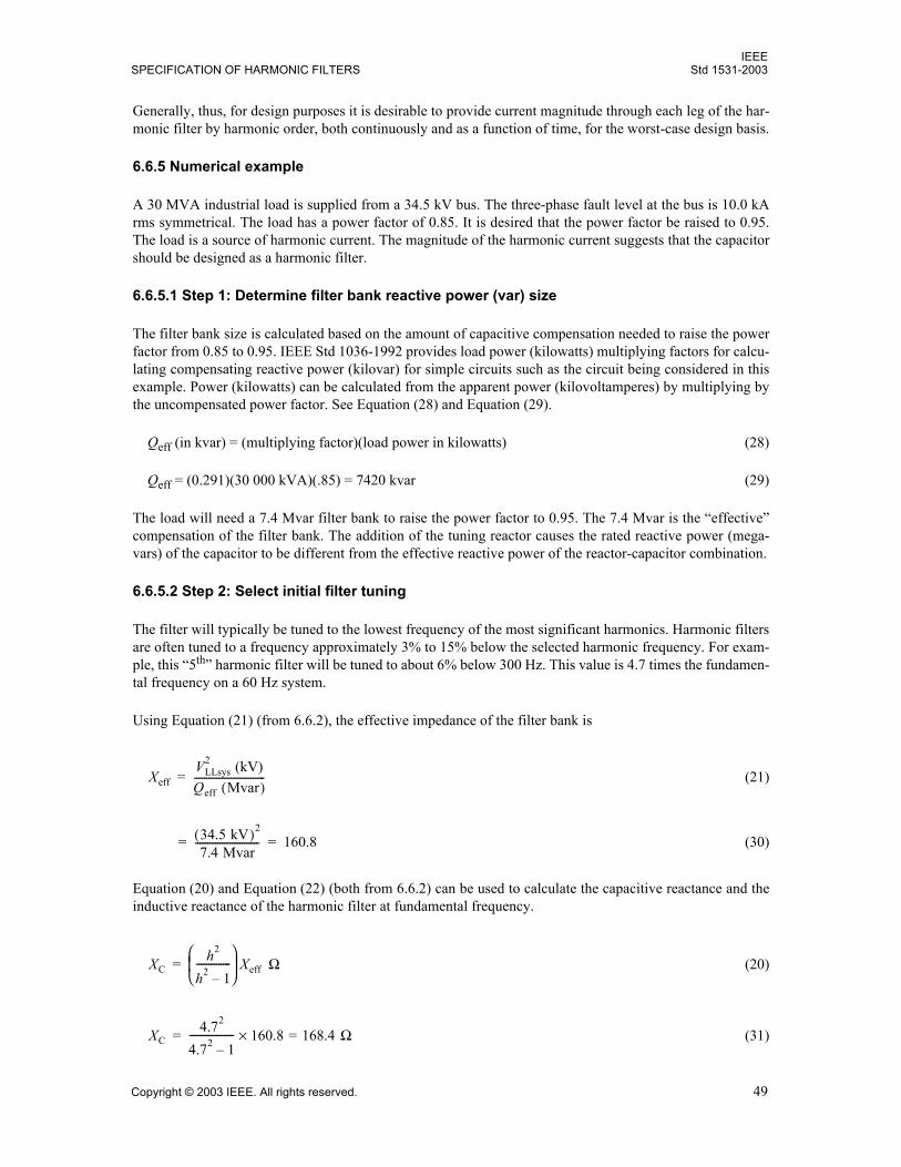
IEEESPECIFICATION OF HARMONIC FILTERS Std 1531-2003
Copyright © 2003 IEEE. All rights reserved. 49
Generally, thus, for design purposes it is desirable to provide current magnitude through each leg of the har-monic filter by harmonic order, both continuously and as a function of time, for the worst-case design basis.
6.6.5 Numerical example
A 30 MVA industrial load is supplied from a 34.5 kV bus. The three-phase fault level at the bus is 10.0 kArms symmetrical. The load has a power factor of 0.85. It is desired that the power factor be raised to 0.95.The load is a source of harmonic current. The magnitude of the harmonic current suggests that the capacitorshould be designed as a harmonic filter.
6.6.5.1 Step 1: Determine filter bank reactive power (var) size
The filter bank size is calculated based on the amount of capacitive compensation needed to raise the powerfactor from 0.85 to 0.95. IEEE Std 1036-1992 provides load power (kilowatts) multiplying factors for calcu-lating compensating reactive power (kilovar) for simple circuits such as the circuit being considered in thisexample. Power (kilowatts) can be calculated from the apparent power (kilovoltamperes) by multiplying bythe uncompensated power factor. See Equation (28) and Equation (29).
Qeff (in kvar) = (multiplying factor)(load power in kilowatts) (28)
Qeff = (0.291)(30 000 kVA)(.85) = 7420 kvar (29)
The load will need a 7.4 Mvar filter bank to raise the power factor to 0.95. The 7.4 Mvar is the effectivecompensation of the filter bank. The addition of the tuning reactor causes the rated reactive power (mega-vars) of the capacitor to be different from the effective reactive power of the reactor-capacitor combination.
6.6.5.2 Step 2: Select initial filter tuning
The filter will typically be tuned to the lowest frequency of the most significant harmonics. Harmonic filtersare often tuned to a frequency approximately 3% to 15% below the selected harmonic frequency. For exam-ple, this 5th harmonic filter will be tuned to about 6% below 300 Hz. This value is 4.7 times the fundamen-tal frequency on a 60 Hz system.
Using Equation (21) (from 6.6.2), the effective impedance of the filter bank is
(21)
(30)
Equation (20) and Equation (22) (both from 6.6.2) can be used to calculate the capacitive reactance and theinductive reactance of the harmonic filter at fundamental frequency.
(20)
(31)
XeffVLLsys
2 (kV)Qeff Mvar( )-----------------------------=
34.5 kV( )2
7.4 Mvar-------------------------- 160.8= =
XCh2
h2 1--------------
Xeff Ω=
XC4.72
4.72 1------------------ 160.8 168.4=× Ω=
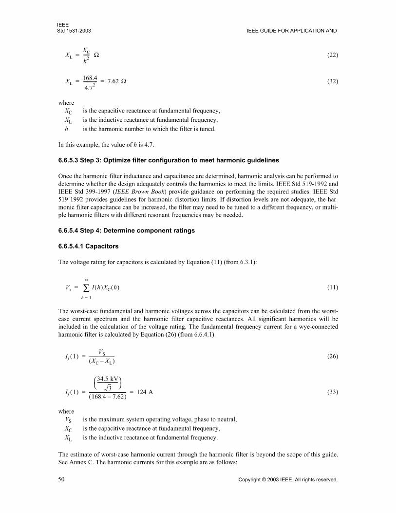
IEEEStd 1531-2003 IEEE GUIDE FOR APPLICATION AND
50 Copyright © 2003 IEEE. All rights reserved.
(22)
(32)
whereXC is the capacitive reactance at fundamental frequency,XL is the inductive reactance at fundamental frequency, h is the harmonic number to which the filter is tuned.
In this example, the value of h is 4.7.
6.6.5.3 Step 3: Optimize filter configuration to meet harmonic guidelines
Once the harmonic filter inductance and capacitance are determined, harmonic analysis can be performed todetermine whether the design adequately controls the harmonics to meet the limits. IEEE Std 519-1992 andIEEE Std 399-1997 (IEEE Brown Book) provide guidance on performing the required studies. IEEE Std519-1992 provides guidelines for harmonic distortion limits. If distortion levels are not adequate, the har-monic filter capacitance can be increased, the filter may need to be tuned to a different frequency, or multi-ple harmonic filters with different resonant frequencies may be needed.
6.6.5.4 Step 4: Determine component ratings
6.6.5.4.1 Capacitors
The voltage rating for capacitors is calculated by Equation (11) (from 6.3.1):
(11)
The worst-case fundamental and harmonic voltages across the capacitors can be calculated from the worst-case current spectrum and the harmonic filter capacitive reactances. All significant harmonics will beincluded in the calculation of the voltage rating. The fundamental frequency current for a wye-connectedharmonic filter is calculated by Equation (26) (from 6.6.4.1).
(26)
(33)
whereVS is the maximum system operating voltage, phase to neutral,XC is the capacitive reactance at fundamental frequency,XL is the inductive reactance at fundamental frequency.
The estimate of worst-case harmonic current through the harmonic filter is beyond the scope of this guide.See Annex C. The harmonic currents for this example are as follows:
XLXC
h2------ Ω=
XL168.44.72
------------- 7.62 Ω= =
Vr I h( )XC h( )h 1=
∞
∑=
If 1( )VS
XC XL( )------------------------=
If 1( )
34.5 kV3
-------------------
168.4 7.62( )---------------------------------- 124 A= =
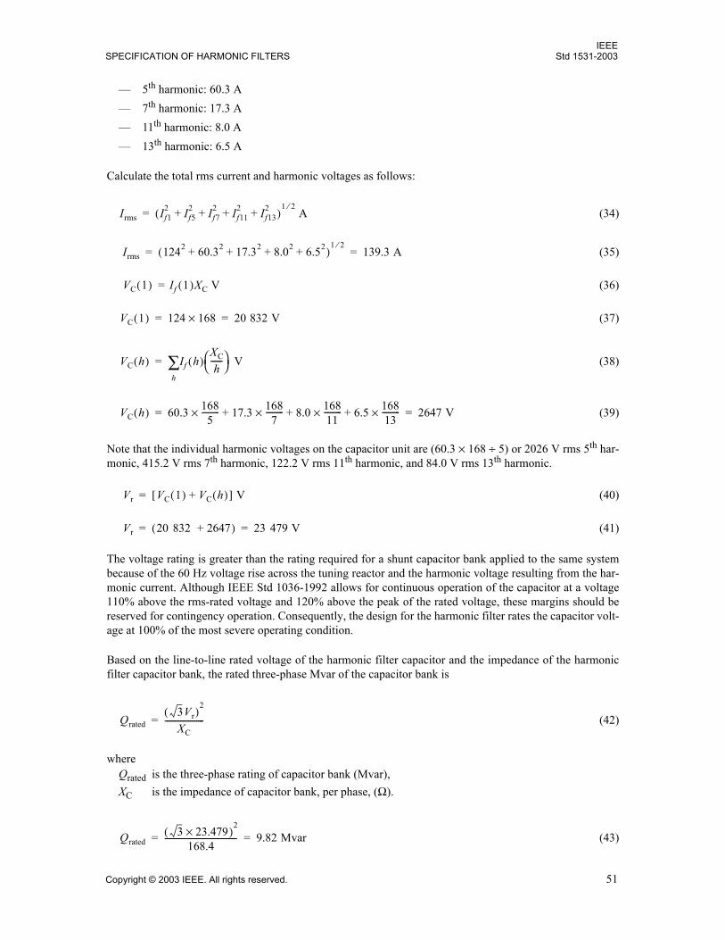
IEEESPECIFICATION OF HARMONIC FILTERS Std 1531-2003
Copyright © 2003 IEEE. All rights reserved. 51
5th harmonic: 60.3 A 7th harmonic: 17.3 A 11th harmonic: 8.0 A 13th harmonic: 6.5 A
Calculate the total rms current and harmonic voltages as follows:
(34)
(35)
(36)
(37)
V (38)
(39)
Note that the individual harmonic voltages on the capacitor unit are (60.3 × 168 ÷ 5) or 2026 V rms 5th har-monic, 415.2 V rms 7th harmonic, 122.2 V rms 11th harmonic, and 84.0 V rms 13th harmonic.
(40)
(41)
The voltage rating is greater than the rating required for a shunt capacitor bank applied to the same systembecause of the 60 Hz voltage rise across the tuning reactor and the harmonic voltage resulting from the har-monic current. Although IEEE Std 1036-1992 allows for continuous operation of the capacitor at a voltage110% above the rms-rated voltage and 120% above the peak of the rated voltage, these margins should bereserved for contingency operation. Consequently, the design for the harmonic filter rates the capacitor volt-age at 100% of the most severe operating condition.
Based on the line-to-line rated voltage of the harmonic filter capacitor and the impedance of the harmonicfilter capacitor bank, the rated three-phase Mvar of the capacitor bank is
(42)
whereQrated is the three-phase rating of capacitor bank (Mvar),XC is the impedance of capacitor bank, per phase, (Ω).
(43)
Irms If12 If5
2 If72 If11
2 If132+ + + +( )
1 2⁄ A=
Irms 1242 60.32 17.32 8.02 6.52+ + + +( )1 2⁄
139.3 A= =
VC 1( ) If 1( )XC V=
VC 1( ) 124 168× 20 832 V= =
VC h( ) If h( )h∑
XC
h------
=
VC h( ) 60.3 1685
---------× 17.3+ 1687
---------× 8.0+ 16811---------× 6.5+ 168
13---------× 2647 V= =
Vr VC 1( ) VC h( )+[ ] V=
Vr 20 832 2647+( ) 23 479 V= =
Qrated3Vr( )
2
XC--------------------=
Qrated3 23.479×( )
2
168.4------------------------------------- 9.82 Mvar= =
IEEEStd 1531-2003 IEEE GUIDE FOR APPLICATION AND
52 Copyright © 2003 IEEE. All rights reserved.
This value is significantly greater than the required effective reactive power (megavars) calculated at thebeginning of the example (7.4 Mvar, in 6.6.5.1). The reason is that the capacitor voltage rating is higher thannominal system voltage as explained previously.
The nominal capacitor current based on rated voltage and rated kvar is calculated to be
(44)
(45)
The actual rms current that will flow in the harmonic filter was calculated in Equation (35) as 139.3 A.
Based on IEEE Std 1036-1992,18 the total rms current through the harmonic filter capacitor units should beless than 135% of the capacitor unit nominal current based on rated kvar and rated voltage. The nominal cur-rent for the sample design is 139.3 A rms. The Irms, current duty, with harmonics is 139.6 A rms. Therefore,the current duty is 100.2% of nominal current and meets the IEEE Std 1036-1992 requirement.
The final check in the harmonic filter design is to see that the dielectric heating of the harmonic filter capac-itor is acceptable. The dielectric heating is evaluated by the inequality in Equation (6) from (4.2.2):
(6)
To compare against the three-phase rating of the capacitor bank, the left-hand side of the inequality is multi-plied by three.
(46)
The inequality is satisfied with substantial margin, the dielectric heating of the proposed design issatisfactory.
It appears that the harmonic filter capacitor is conservatively designed and meets all requirements. Addi-tional capability can be built in to handle other harmonics on the system from unidentified sources that willbe drawn to the harmonic filter and could otherwise lead to overloading. Also, as additional loads are addedin the area, the new harmonics will be drawn to the low impedance of the filter and may lead to harmonicoverloading. Some overrating should be built into the design to allow for this contingency. The incrementalcost per kilovar of adding capacity for harmonic absorption to a harmonic filter is much lower than the aver-age cost per kilovar of the harmonic filter. Therefore, a generous margin in specifying the harmonic duty isgenerally desirable.
6.6.5.4.2 Harmonic filter reactors
In this example, the reactance has already been calculated (7.62 Ω). The harmonic current spectrum was alsopreviously calculated. The short-circuit current at the bus was given as 10 kA. However, this value is not theshort-circuit current rating of the harmonic filter reactor. The symmetrical short-circuit current for the har-monic filter reactor is calculated based on the harmonic filter reactor impedance in series with the sourceimpedance (when the harmonic filter reactor is mounted on the source side of the harmonic filter capacitor).The source impedance is as follows:
18This information is from the referenced standard(s) and does not transplant these limits to this guide. See the first paragraph ofClause 2
InomQrated (kvar)
3 Vrated (kV)----------------------------------=
Inom9.82 Mvar 1000×( )3 3 23.5 kV×( )×
--------------------------------------------------- 139.3 A= =
V h( )I h( )( )h∑ 1.35Qrated≤
3 20.8 124× 2.0+ 60.3× 0.4+ 17.3× 0.1+ 8.0× 0.1+ 6.5×( )× 1.35 9820×≤8124 13 257 ≤
IEEESPECIFICATION OF HARMONIC FILTERS Std 1531-2003
Copyright © 2003 IEEE. All rights reserved. 53
(47)
(48)
where Vll nom is the nominal system line-to-line voltage,ISCBUS is the available short-circuit current at the bus.
The symmetrical short-circuit rating of the harmonic filter reactor is
(49)
(50)
The harmonic filter reactor symmetrical short-circuit rating must be at least 2.07 kA. The fault duration willdepend upon protective relaying and circuit breaker operating times. The asymmetrical short-circuit ratingcan be calculated based on the X/R ratio of the system. The Q of the harmonic filter reactor is usually above50. The exact number is not critical in many designs. Digital simulations (Step 3 of the design process; see6.6.3) may be used to assess the sensitivity to the value.
6.6.5.4.3 Circuit breaker or switch
The short-circuit current for the switching device is essentially the bus fault current (10 kA) and is not thesame as the short-circuit current for the harmonic filter reactor specification. Although a capacitor switch isnot required to interrupt short-circuit current (as opposed to a circuit breaker, which is required to do so), itmust be able to handle short-circuit current flow through it for the close-and-latch and momentaryrequirements.
The capacitive current switching requirement must include consideration for the worst combination of max-imum system voltage, capacitance tolerances, and harmonics.
6.6.6 Specific filter application information
6.6.6.1 Arc furnaces
6.6.6.1.1 General
Arc furnace installations employ various types of harmonic filters based on a variety of application objec-tives. Arc furnaces operate around a power factor of 0.7 to 0.85 lagging and require reactive compensationto correct the power factor. In order to apply power factor correction to a furnace circuit, capacitor banks aregenerally applied in single-tuned passive harmonic filter configurations. The harmonic filters will improvethe circuit power factor and mitigate harmonics generated by the arc furnace and static var compensator(SVC) equipment that might have been installed to control voltage flicker. The result is improved power fac-tor and a reduction in harmonic distortion levels. In addition to the harmonic filters applied on the arc
XS
Vll nom
3--------------
ISCBUS--------------------=
XS
34.5 kV3
-------------------
10 kA------------------------- 1.99 Ω= =
ISC
Vll nom
3--------------
XS XL+--------------------=
ISC
34.5 kV3
-------------------
1.99 7.63 Ω+---------------------------------- 2.07 kA= =
IEEEStd 1531-2003 IEEE GUIDE FOR APPLICATION AND
54 Copyright © 2003 IEEE. All rights reserved.
furnace circuit, the rolling mill of the steel manufacturing facilities will also employ harmonic filters toimprove power factor and also to mitigate the harmonics generated by the drive systems in the rolling mill.
The design of the harmonic filters will require knowledge of the actual harmonics generated by the furnaces.In most applications, multiple harmonic filters are needed. They can be designed based on the harmonic dutyat the filter installation location. The total amount of reactive compensation needed from the filters can bedivided into a number of filters based on the percent harmonic current. The tuned frequencies and the num-ber of filters needed are usually based on the plant operating objectives, such as power factor requirements,harmonic limits, voltage flicker limits, SVC limits, etc.
The harmonic filters used in arc furnace applications are typically connected permanently to the furnace cir-cuit. Some installations employ a switching scheme where the harmonic filters will be switched based on thefurnace loading.
6.6.6.1.2 Harmonic sources in arc furnace applications
A variety of different arc furnace types are utilized by steel manufacturers based on the plant production.They can be generally divided into two main types: ac furnaces and dc furnaces. Large steel manufacturersuse ac furnaces. These ac furnaces can be scrap furnaces or ladle furnaces. The scrap furnaces generate themost significant amount of harmonics, and these furnaces are generally large. The ladle furnaces also gener-ate harmonics, but are less severe compared to the scrap furnaces. Large steel manufacturers also use the dcfurnaces, and they are a popular application now. The dc furnaces are typically 12-pulse types, and they canbe operated as 6-pulse systems. There are also dc furnaces that are higher pulse order, such as 48 pulse, andthey can operate as various lesser pulse systems in abnormal conditions. The principal harmonics generatedby the dc furnaces are the typical h = p ± 1 harmonics, where the magnitude of each harmonic is approxi-mately the fundamental current divided by the order of the harmonic . Both ac and dc arcfurnaces also generate some level of noncharacteristic and interharmonics that must also be addressed oraccounted for in the design of the harmonic filters. The presence of noncharacteristic harmonics and inter-harmonics suggest that it may be necessary to control the parallel resonance modes at those frequencies toavoid excessive amplifications of harmonics, which may produce visible flicker from beating frequencies.
6.6.6.1.3 Arc furnace transformer energizations
Another common harmonic source in an arc furnace installation is the energization of the arc furnace trans-former, typically 50 to 100 times a day. Although a transformer energization is a quasi-transient event, itcould last from as short as 20 cycles to as long as minutes based on the circuit. These energizations eventsresult in inrush currents that are rich in harmonics. The furnace transformer energization inrush currentsshould also be considered as a primary source of harmonics when evaluating harmonic filter componentratings.
6.6.6.1.4 Harmonic filter types
The harmonic filter types used are generally based on the arc furnace type. In some applications, otherobjectives, such as minimizing the total harmonic voltage distortion at the point of common coupling, couldalso be a factor in the type of harmonic filters used. It should also be noted that some installations wouldhave combinations of furnace types (e.g., ac-scrap, ac-ladle, dc) connected at the same bus. In this case, theoverall system should be evaluated for the most effective harmonic filtering scheme. Double-tuned har-monic filters are also used in some applications.
a) AC arc furnacesscrap furnaces and ladle furnaces. The scrap furnaces employ 2nd, 3rd, 4th, and5th harmonic filters. Based on the installation, any combination of these filters can be found. Thelower order harmonic filters, mainly the 2nd and the 3rd harmonic filters, have to be sized to absorbthe furnace transformer energization inrush currents and the resulting overvoltages in addition to the
I h( ) I 1( ) h⁄≈[ ]
IEEESPECIFICATION OF HARMONIC FILTERS Std 1531-2003
Copyright © 2003 IEEE. All rights reserved. 55
steady-state arc furnace arcing conditions. The harmonic filters are generally passive, single-tuned,shunt filters. More complex dual frequency and C-type harmonic filters are also employed.
b) DC arc furnaces. The dc furnaces employ 5th, 7th, and 11th harmonic filters as a minimum to filterthe harmonics generated by the rectification. Due to the harmonics generated by the arcing process,2nd, 3rd, and/or 4th harmonic filters are frequently used. The harmonic filters are generally passive,single-tuned, shunt filters. More complex harmonic filters tuned to multiple frequencies are alsoemployed.
6.6.6.1.5 Harmonic filter ratings
The harmonic filter ratings should be evaluated based on various operating conditions. The conditions thatthe harmonic filter should withstand include the following:
a) No load condition. This condition is when the harmonic filter is connected to the system with the arcfurnace not operating. The bus voltage will increase, and the increased bus voltage will increase theharmonic filter current. In this case, it can be assumed that the harmonic currents are reducedbecause the arc furnace is off line.
b) Worst-case steady-state arcing condition. The most unstable arcing, with the greatest harmonic gen-eration, occurs at the beginning of the melt cycle, when the arcing is to unmelted scrap. During atypical melt cycle, which normally lasts approximately 1 hr, the furnace is charged (i.e., scrap metalis added) twice. Each time the worst-case steady-state arcing (bore-in) lasts approximately 5 min to15 min, depending on numerous variables. The harmonic filter should be able to withstand the har-monic currents absorbed due to this condition.
c) Momentary condition for furnace transformer energizations. This condition is the most limiting,especially when lower order harmonic filters (e.g., 2nd, 3rd, 4th) are present. The harmonic filtershould be rated to handle this condition.
d) Switching the circuit breaker or vacuum switch. The harmonic filter should be able to withstand thetransients created by these switching events.
e) Back-to-back switching of harmonic filters on the same bus. The transients created by harmonic fil-ters (or capacitor banks) switched on the same bus should be evaluated. The harmonic filter shouldbe able to withstand these transients, which are not a concern in switching harmonic filters due to theinductance of the harmonic filter reactors.
6.6.6.2 Steel rolling mills
The rolling mill of a steel manufacturing facility will typically include a variety of 6-pulse and 12-pulsedrive systems. The harmonics generated by these drive systems are typically the 1/h type harmonics.
The rolling mills typically employ 5th, 7th, and 11th harmonic filters as a minimum. The harmonic filters aregenerally passive, single-tuned, LC shunt filters. More complex harmonic filters tuned to multiple frequen-cies are also employed. Some installations will also have lower order harmonic filters installed.
Some rolling mills utilize cycloconverters instead of traditional 6-pulse or 12-pulse drives. A cycloconvertermay produce typical 1/h harmonics at times, but also produces interharmonics. Harmonic filter design mustaccommodate both 1/h harmonics and interharmonics.
IEEEStd 1531-2003 IEEE GUIDE FOR APPLICATION AND
56 Copyright © 2003 IEEE. All rights reserved.
Annex A
(informative)
Bibliography
[B1] IEEE 100, The Authoritative Dictionary of IEEE Standards Terms, Seventh Edition.
[B2] IEEE Power Engineering Society, IEEE Tutorial on Harmonics Modeling and Simulation, IEEECatalog Number: 98TP125-0.
[B3] IEEE Task Force, The Effects of Power System Harmonics on Power System Equipment and Loads,IEEE Transactions on Power Apparatus and Systems, vol. PAS-104, no. 9, pp 25552563, Sept. 1985.
[B4] Ludbrook, A., Harmonic Filters for Notch Reduction, IEEE Trans. on Industry Applications, vol. IA-24, no. 5, Sept./Oct. 1988.
[B5] Paice, Derek A., Power Electronic Converter Harmonics: Multipulse Methods for Clean Power. NewYork, NJ: IEEE Press, 1996.
[B6] Rice, D. E., Adjustable Speed Drive and Power Rectifier Harmonics, The Effect on Power SystemComponents, IEEE Transactions on Industrial Applications, vol. IA-22, no. 1, pp 161177, Jan./Feb. 1986.
[B7] Wagner, V., et. al., Effects of Harmonics on Equipment, IEEE Trans. on Power Delivery. vol. 8,no. 2, pp 672680, Apr. 1993.
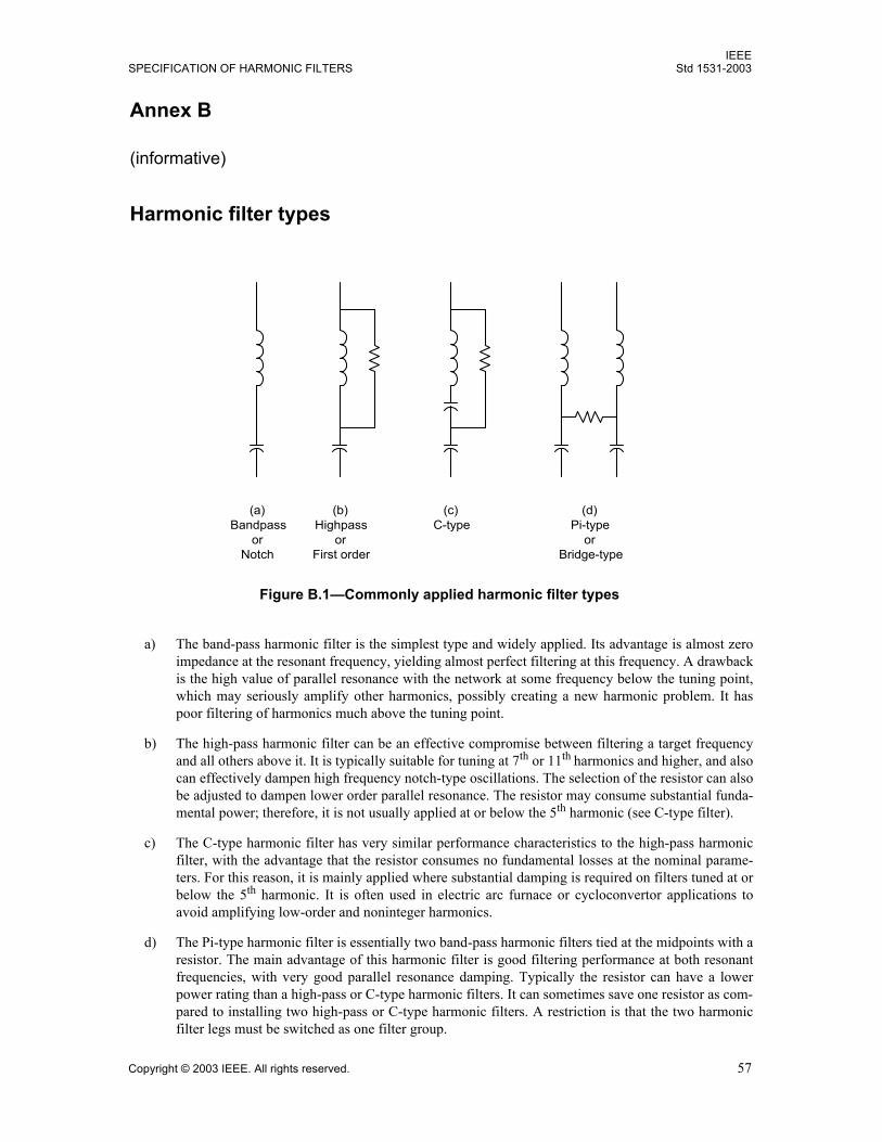
IEEESPECIFICATION OF HARMONIC FILTERS Std 1531-2003
Copyright © 2003 IEEE. All rights reserved. 57
Annex B
(informative)
Harmonic filter types
a) The band-pass harmonic filter is the simplest type and widely applied. Its advantage is almost zeroimpedance at the resonant frequency, yielding almost perfect filtering at this frequency. A drawbackis the high value of parallel resonance with the network at some frequency below the tuning point,which may seriously amplify other harmonics, possibly creating a new harmonic problem. It haspoor filtering of harmonics much above the tuning point.
b) The high-pass harmonic filter can be an effective compromise between filtering a target frequencyand all others above it. It is typically suitable for tuning at 7th or 11th harmonics and higher, and alsocan effectively dampen high frequency notch-type oscillations. The selection of the resistor can alsobe adjusted to dampen lower order parallel resonance. The resistor may consume substantial funda-mental power; therefore, it is not usually applied at or below the 5th harmonic (see C-type filter).
c) The C-type harmonic filter has very similar performance characteristics to the high-pass harmonicfilter, with the advantage that the resistor consumes no fundamental losses at the nominal parame-ters. For this reason, it is mainly applied where substantial damping is required on filters tuned at orbelow the 5th harmonic. It is often used in electric arc furnace or cycloconvertor applications toavoid amplifying low-order and noninteger harmonics.
d) The Pi-type harmonic filter is essentially two band-pass harmonic filters tied at the midpoints with aresistor. The main advantage of this harmonic filter is good filtering performance at both resonantfrequencies, with very good parallel resonance damping. Typically the resistor can have a lowerpower rating than a high-pass or C-type harmonic filters. It can sometimes save one resistor as com-pared to installing two high-pass or C-type harmonic filters. A restriction is that the two harmonicfilter legs must be switched as one filter group.
Figure B.1Commonly applied harmonic filter types
(a)Bandpass
orNotch
(b)Highpass
orFirst order
(c)C-type
(d)Pi-type
orBridge-type
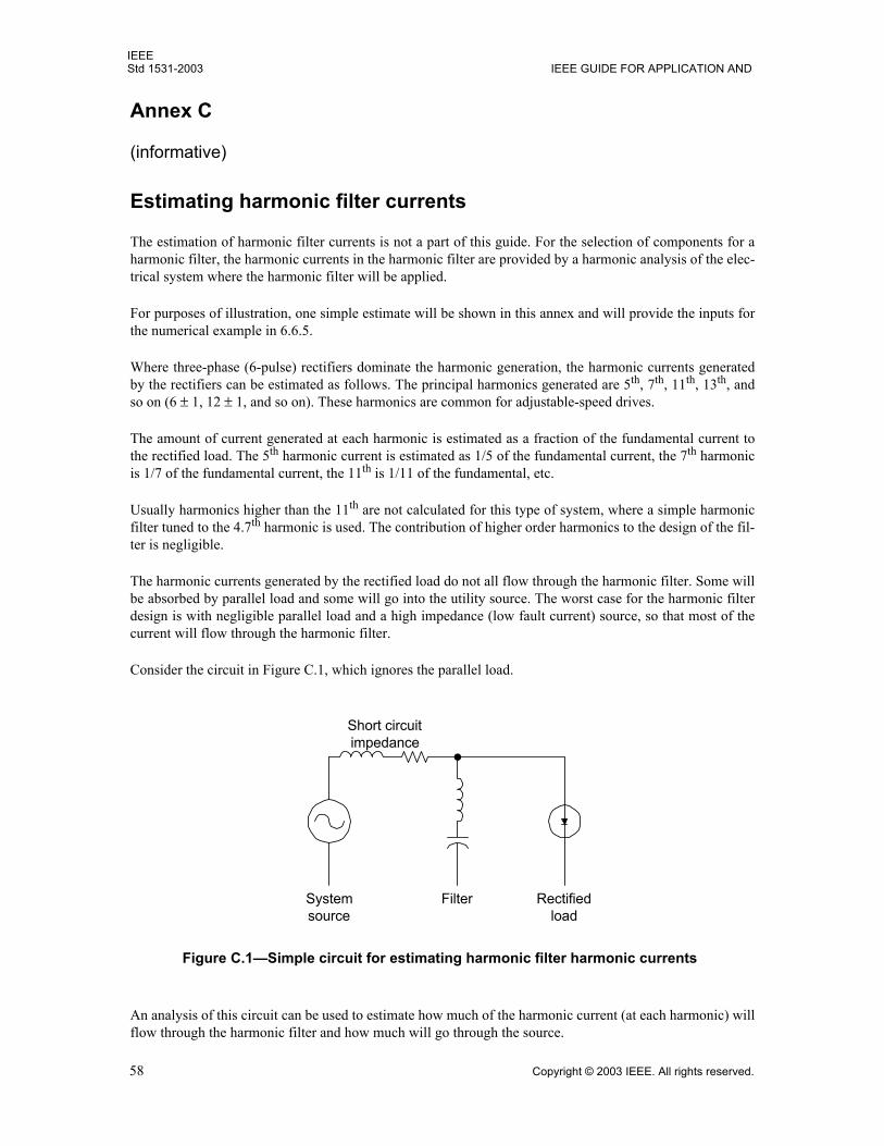
IEEEStd 1531-2003 IEEE GUIDE FOR APPLICATION AND
58 Copyright © 2003 IEEE. All rights reserved.
Annex C
(informative)
Estimating harmonic filter currents
The estimation of harmonic filter currents is not a part of this guide. For the selection of components for aharmonic filter, the harmonic currents in the harmonic filter are provided by a harmonic analysis of the elec-trical system where the harmonic filter will be applied.
For purposes of illustration, one simple estimate will be shown in this annex and will provide the inputs forthe numerical example in 6.6.5.
Where three-phase (6-pulse) rectifiers dominate the harmonic generation, the harmonic currents generatedby the rectifiers can be estimated as follows. The principal harmonics generated are 5th, 7th, 11th, 13th, andso on (6 ± 1, 12 ± 1, and so on). These harmonics are common for adjustable-speed drives.
The amount of current generated at each harmonic is estimated as a fraction of the fundamental current tothe rectified load. The 5th harmonic current is estimated as 1/5 of the fundamental current, the 7th harmonicis 1/7 of the fundamental current, the 11th is 1/11 of the fundamental, etc.
Usually harmonics higher than the 11th are not calculated for this type of system, where a simple harmonicfilter tuned to the 4.7th harmonic is used. The contribution of higher order harmonics to the design of the fil-ter is negligible.
The harmonic currents generated by the rectified load do not all flow through the harmonic filter. Some willbe absorbed by parallel load and some will go into the utility source. The worst case for the harmonic filterdesign is with negligible parallel load and a high impedance (low fault current) source, so that most of thecurrent will flow through the harmonic filter.
Consider the circuit in Figure C.1, which ignores the parallel load.
An analysis of this circuit can be used to estimate how much of the harmonic current (at each harmonic) willflow through the harmonic filter and how much will go through the source.
Figure C.1Simple circuit for estimating harmonic filter harmonic currents
Short circuitimpedance
Systemsource
Filter Rectifiedload
IEEESPECIFICATION OF HARMONIC FILTERS Std 1531-2003
Copyright © 2003 IEEE. All rights reserved. 59
The system source short-circuit impedance is determined at the bus where the harmonic filter will beinstalled. The short-circuit impedance of interest is the highest (lowest short-circuit current) that will occurduring a contingency when the plant is still operating, considering possible changes in the utility source con-figuration, single versus paralleled source transformers, etc.anything that will affect the source imped-ance. The usual short-circuit diagram only shows the maximum short-circuit current, which is important forequipment selection and short-circuit coordination, but not for harmonic filter design.
The effective rating of the filter (kilovars) is determined by the system requirements for voltage support,elimination of power factor penalty, etc.
The rated current of the rectifier load should be generously overestimated to account for possible additionsto the plant and for other sources of harmonic current on the electrical system that may contribute harmoniccurrent to the harmonic filter.
The harmonic currents generated by the rectified load are estimated as indicated near the beginning of thisannex (e.g., 1/5th for the 5th harmonic). Using these harmonic currents and the parallel impedance of thefilter and source, the harmonic voltage may be estimated at each harmonic order (voltage = current ×impedance).
Using the harmonic voltage and the harmonic filter impedance at a given harmonic, the harmonic currentthrough the harmonic filter at that frequency may be estimated.
Figure C.2 presents a spreadsheet that illustrates these calculations.
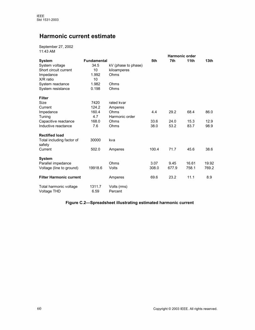
IEEEStd 1531-2003
60 Copyright © 2003 IEEE. All rights reserved.
Figure C.2Spreadsheet illustrating estimated harmonic current
Harmonic current estimateSeptember 27, 200211:43 AM
System Fundamental 5th 7th 11th 13thSystem voltage 34.5 kV (phase to phase)Short circuit current 10 kiloamperesImpedance 1.992 OhmsX/R ratio 10System reactance 1.982 OhmsSystem resistance 0.198 Ohms
FilterSize 7420 rated kvarCurrent 124.2 AmperesImpedance 160.4 Ohms 4.4 29.2 68.4 86.0Tuning 4.7 Harmonic orderCapacitive reactance 168.0 Ohms 33.6 24.0 15.3 12.9Inductive reactance 7.6 Ohms 38.0 53.2 83.7 98.9
Rectified loadTotal including factor of safety
30000 kva
Current 502.0 Amperes 100.4 71.7 45.6 38.6
SystemParallel impedance Ohms 3.07 9.45 16.61 19.92Voltage (line to ground) 19918.6 Volts 308.0 677.9 758.1 769.2
Filter Harmonic current Amperes 69.6 23.2 11.1 8.9
Total harmonic voltage 1311.7 Volts (rms)Voltage THD 6.59 Percent
Harmonic order