Embed Size (px)
Citation preview
Trouble Shooting Information for C7000VP series
Page 1 Rev. 2.0 2010/09/17
imagePRESS C7000VP Series Trouble Shooting Information
Trouble Shooting Information for C7000VP series
Page 2 Rev. 2.0 2010/09/17
Table of Contents
1 Error Code ····································································································································· 5
1.1 E000-0102 ·········································································································································· 5
1.2 E007-0001 ·········································································································································· 6
1.3 E012-1080 ·········································································································································· 7
1.4 E014-0100 ·········································································································································· 7
1.5 E016 Photosensitive drum cleaner motor lock ···································································· 8
1.6 E018 ······················································································································································ 9
1.7 E061-0181 ········································································································································ 11
1.8 E062-0300 ········································································································································ 11
1.9 E065-0201 ········································································································································ 12
1.10 E077-0001 ····································································································································· 13
1.11 E078-0001 ····································································································································· 13
1.12 E202-0001 ····································································································································· 14
1.13 E260-2000, E260-0002, E227-0001 ···················································································· 15
1.14 E260-2004 Power Supply Error (ITB Driver PCB right 13V) ···································· 15
1.15 E512-8011 ····································································································································· 16
1.16 E514-8001 only at first power-on in the morning ························································· 18
1.17 E578 ·················································································································································· 18
1.18 E590-8003 ····································································································································· 19
1.19 E747-051B ····································································································································· 19
1.20 E750-0002 ····································································································································· 20
1.21 E750-2012 ····································································································································· 20
1.22 E804-0001 ····································································································································· 21
1.23 E805-0404 ····································································································································· 23
1.24 E805-0701 ····································································································································· 24
1.25 E822-0903 ····································································································································· 25
1.26 E020 ·················································································································································· 26
1.27 E194 and Color Registration Failure ···················································································· 31
1.28 E842-0211 -> New item ········································································································· 42
1.29 E750-2012 at installation -> New item ·········································································· 43
1.30 E805-Y701 -> Additional contents ···················································································· 45
2 Operational Failure ················································································································· 47
2.1 Message prompting for toner supply ····················································································· 47
2.2 Message ‘Check: Punch waste tray’ ··················································································· 48
2.3 Cannot print in spite of ‘Printing’ indication ···································································· 49
2.4 Unavailable RUI although same IP address has been specified ·································· 49
2.5 Directory server name does not appear as SMB directory under browse ············· 50
2.6 ‘Invalid user data’ displays on browser when connecting to RUI ····························· 51
2.7 When importing paper database via RUI, parameters are not carried over ············ 52
2.8 Full adjustment for auto gradation cannot be completed·············································· 52
2.9 Noise from around developing drive assembly/Cracked developing drive gear ··· 53
2.10 Although Tray A is designated as delivery outlet, paper is delivered to Tray B.58
2.11 The red warning light blinks and print operation is not accepted -> New item58
2.12 Noise occurred at operating the refresh roller -> New item ····································· 59
2.13 The magenta developing assembly is not activated -> New item ··························· 60
2.14 Breakage of the splatter prevention sheet at the end of the developing assembly -> New
item 60
Trouble Shooting Information for C7000VP series
Page 3 Rev. 2.0 2010/09/17
3 Image Quality ····························································································································· 62
3.1 Y Tiger / BK Tiger ························································································································ 62
3.2 Uneven gloss area appears at end of output images: Silicon oil is depleted ········· 64
3.3 Soiled back side due to toner at secondary transfer external roller ························ 66
3.4 Soiled back side cases reported from field ········································································· 66
3.5 Magenta fogging throughout page /E020-02b1 during continuous printing job ···· 67
3.6 Color displacement in main scanning direction ································································· 68
3.7 Uneven density due to toner-coating failure of sleeve ·················································· 69
3.8 Trace of delivery reversing roller (uneven gloss) on 1st side of duplex in continuous printing
70
3.9 Glossy Lines equivalent to A4R or LTRR width ································································ 71
3.10 Dirt of pin hole (ring mark) ······································································································ 72
3.11 Trace of bypass decurler belt (uneven gloss) on 1st side of duplex in continuous printing
73
3.12 Wax mark in tandem feeding mode ······················································································· 74
3.13 White spots appear at 68mm intervals ··············································································· 76
3.14 3.7mm Pitch Banding ················································································································· 77
3.15 Density difference on image between front side and rear side ································ 78
3.16 Boomerang ····································································································································· 78
3.17 Hue variation ································································································································· 79
3.18 Uneven image with approx. 60mm pitch in main scanning direction ······················· 79
3.19 Sleeve ghost (shadow image) ································································································· 80
3.20 Streaks due to uneven gloss on the coated paper (sub scanning) ························· 81
3.21 Starter overflow ··························································································································· 82
3.22 Hue variation - 2 ························································································································· 83
3.23 Soiled back side of image (toner overflow from the secondary transfer cleaner) -> New
item 84
3.24 2mm-pitch banding -> New item ·························································································· 85
3.25 Uneven gloss on image (entire surface) -> New item ·············································· 85
3.26 Uneven gloss on image (unevenness at the center in vertical direction) -> New item
86
3.27 Soiled front side of image (fault in ITB cleaning) -> New item ································ 87
3.28 Color displacement in sub scanning direction -> New item·································· 90
3.29 Distorted toner image due to wax -> New item ························································ 91
3.30 Scratches on images of coated paper -> New item ·············································· 93
4 Jam Code ····································································································································· 94
4.1 010E/0209/020A Jam Code: Spring at cross feeding assembly breaks ················· 94
4.2 012A JAM ········································································································································· 95
4.3 1145 Jam with A4R paper: Timing Belt of Saddle Assembly in Saddle Finisher-AB2 slips off
96
4.4 0114 JAM·········································································································································· 97
4.5 Pick-up failure, multi feed (how to adjust the pick-up air flow) ································· 98
-> New item················································································································································ 98
5 Specification-related issues ····························································································· 104
5.1 Description on fixing roller refresh operation and its execution timing ················· 104
5.2 Specifications for staple capacity of Finisher-AB1/AB2 ············································ 105
5.3 Number of sheets and size specification for saddle stitching ··································· 105
5.4 When uploading DC Controller data with SST, ‘SramDCON’ does not appear on SST
screen ························································································································································· 106
5.5 Description of features of Function Expansion PCB on DC Controller PCB 1-2106
Trouble Shooting Information for C7000VP series
Page 4 Rev. 2.0 2010/09/17
6 Adjustment Items ··················································································································· 107
6.1 Adjustments under [Registering/Editing Custom Paper Types] ······························ 107
6.2 Adjusting the Level of Curl Correction of a Custom Paper Type···························· 118
6.3 Shading correction in the main scanning direction ························································ 119
7 Reference ··································································································································· 120
7.1 Table indicating Fixing Temperature Shift ········································································· 120
7.2 Addition of ‘CP-PRINT’ ·········································································································· 122
8 Operations for Sublog (iPRC7000VP) ········································································· 123
8.1 What is Sublog? ···························································································································· 123
8.2 What is RB-SRAM UNIT? ········································································································· 123
8.3 How to obtain RB-SRAM UNIT ····························································································· 123
8.4 Points to note when collecting Sublog ··············································································· 124
8.5 When RB- SRAM UNIT Is Not Equipped ············································································ 124
8.6 How to Collect Sublog ··············································································································· 124
8.7 Information Required at Log Collection ·············································································· 127
8.8 Points to Note ······························································································································ 127
8.9 Reference Information ··············································································································· 128
Trouble Shooting Information for C7000VP series
Page 5 Rev. 2.0 2010/09/17
1 Error Code 1.1 E000-0102
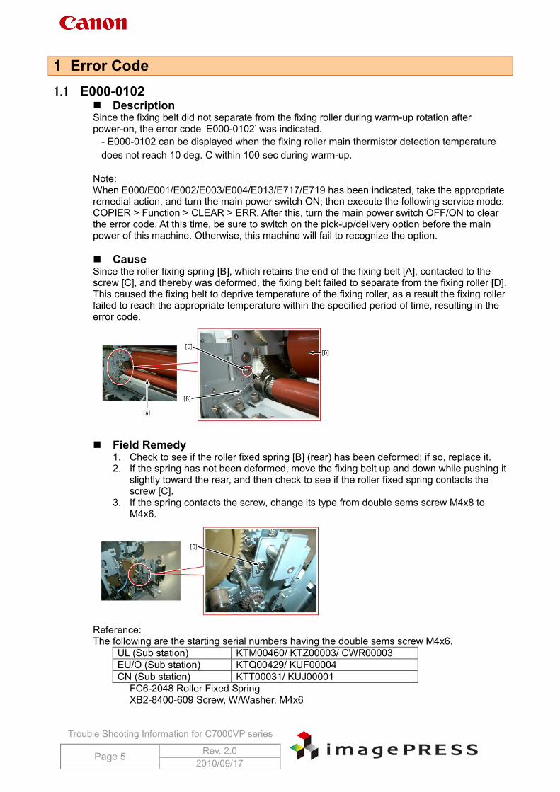
Description Since the fixing belt did not separate from the fixing roller during warm-up rotation after power-on, the error code ‘E000-0102’ was indicated.
- E000-0102 can be displayed when the fixing roller main thermistor detection temperature does not reach 10 deg. C within 100 sec during warm-up.
Note: When E000/E001/E002/E003/E004/E013/E717/E719 has been indicated, take the appropriate remedial action, and turn the main power switch ON; then execute the following service mode: COPIER > Function > CLEAR > ERR. After this, turn the main power switch OFF/ON to clear the error code. At this time, be sure to switch on the pick-up/delivery option before the main power of this machine. Otherwise, this machine will fail to recognize the option. Cause Since the roller fixing spring [B], which retains the end of the fixing belt [A], contacted to the screw [C], and thereby was deformed, the fixing belt failed to separate from the fixing roller [D]. This caused the fixing belt to deprive temperature of the fixing roller, as a result the fixing roller failed to reach the appropriate temperature within the specified period of time, resulting in the error code.
Field Remedy
1. Check to see if the roller fixed spring [B] (rear) has been deformed; if so, replace it. 2. If the spring has not been deformed, move the fixing belt up and down while pushing it
slightly toward the rear, and then check to see if the roller fixed spring contacts the screw [C].
3. If the spring contacts the screw, change its type from double sems screw M4x8 to M4x6.
Reference: The following are the starting serial numbers having the double sems screw M4x6.
UL (Sub station) KTM00460/ KTZ00003/ CWR00003 EU/O (Sub station) KTQ00429/ KUF00004 CN (Sub station) KTT00031/ KUJ00001
FC6-2048 Roller Fixed Spring XB2-8400-609 Screw, W/Washer, M4x6
Trouble Shooting Information for C7000VP series
Page 6 Rev. 2.0 2010/09/17
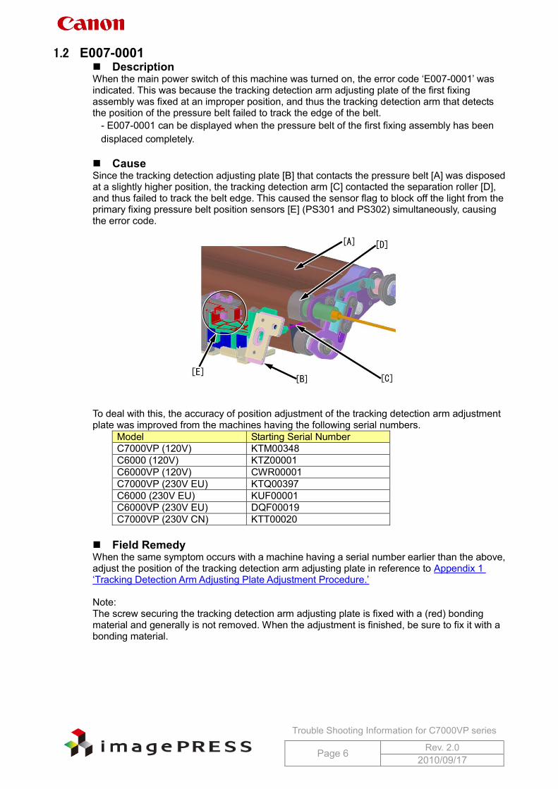
1.2 E007-0001 Description When the main power switch of this machine was turned on, the error code ‘E007-0001’ was indicated. This was because the tracking detection arm adjusting plate of the first fixing assembly was fixed at an improper position, and thus the tracking detection arm that detects the position of the pressure belt failed to track the edge of the belt.
- E007-0001 can be displayed when the pressure belt of the first fixing assembly has been displaced completely.
Cause Since the tracking detection adjusting plate [B] that contacts the pressure belt [A] was disposed at a slightly higher position, the tracking detection arm [C] contacted the separation roller [D], and thus failed to track the belt edge. This caused the sensor flag to block off the light from the primary fixing pressure belt position sensors [E] (PS301 and PS302) simultaneously, causing the error code.
To deal with this, the accuracy of position adjustment of the tracking detection arm adjustment plate was improved from the machines having the following serial numbers.
Model Starting Serial Number C7000VP (120V) KTM00348 C6000 (120V) KTZ00001 C6000VP (120V) CWR00001 C7000VP (230V EU) KTQ00397 C6000 (230V EU) KUF00001 C6000VP (230V EU) DQF00019 C7000VP (230V CN) KTT00020
Field Remedy When the same symptom occurs with a machine having a serial number earlier than the above, adjust the position of the tracking detection arm adjusting plate in reference to Appendix 1 ‘Tracking Detection Arm Adjusting Plate Adjustment Procedure.’ Note: The screw securing the tracking detection arm adjusting plate is fixed with a (red) bonding material and generally is not removed. When the adjustment is finished, be sure to fix it with a bonding material.
Trouble Shooting Information for C7000VP series
Page 7 Rev. 2.0 2010/09/17
1.3 E012-1080 Cause There are some reported instances from the field where E012-0180 occurred because the primary transfer roller was omitted to pressurize at the time of installation. This caused insufficient tension to be applied to the ITB belt and a rotational failure of the belt.
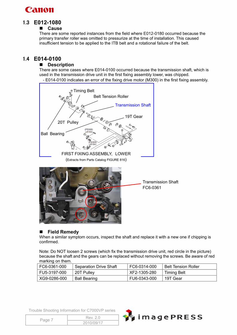
1.4 E014-0100 Description There are some cases where E014-0100 occurred because the transmission shaft, which is used in the transmission drive unit in the first fixing assembly lower, was chipped.
- E014-0100 indicates an error of the fixing drive motor (M300) in the first fixing assembly.
Field Remedy When a similar symptom occurs, inspect the shaft and replace it with a new one if chipping is confirmed. Note: Do NOT loosen 2 screws (which fix the transmission drive unit, red circle in the picture) because the shaft and the gears can be replaced without removing the screws. Be aware of red marking on them. FC6-0361-000 Separation Drive Shaft FC6-0314-000 Belt Tension Roller FU5-3197-000 20T Pulley XF2-1305-280 Timing Belt XG9-0286-000 Ball Bearing FU6-0343-000 19T Gear
FIRST FIXING ASSEMBLY, LOWER (Extracts from Parts Catalog FIGURE 816)
Transmission Shaft
Ball Bearing
20T Pulley
Timing Belt
19T Gear
Belt Tension Roller
Transmission Shaft FC6-0361
Trouble Shooting Information for C7000VP series
Page 8 Rev. 2.0 2010/09/17
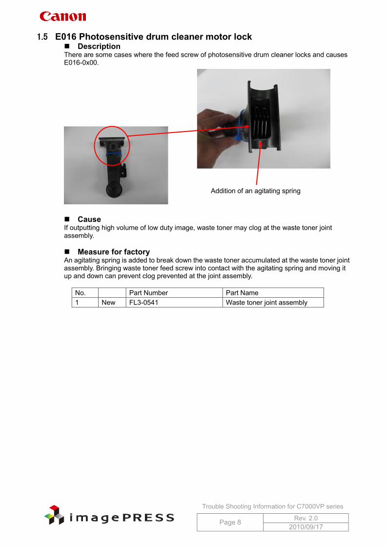
1.5 E016 Photosensitive drum cleaner motor lock Description There are some cases where the feed screw of photosensitive drum cleaner locks and causes E016-0x00.
Cause If outputting high volume of low duty image, waste toner may clog at the waste toner joint assembly. Measure for factory An agitating spring is added to break down the waste toner accumulated at the waste toner joint assembly. Bringing waste toner feed screw into contact with the agitating spring and moving it up and down can prevent clog prevented at the joint assembly.
No. Part Number Part Name 1 New FL3-0541 Waste toner joint assembly
Addition of an agitating spring
Trouble Shooting Information for C7000VP series
Page 9 Rev. 2.0 2010/09/17
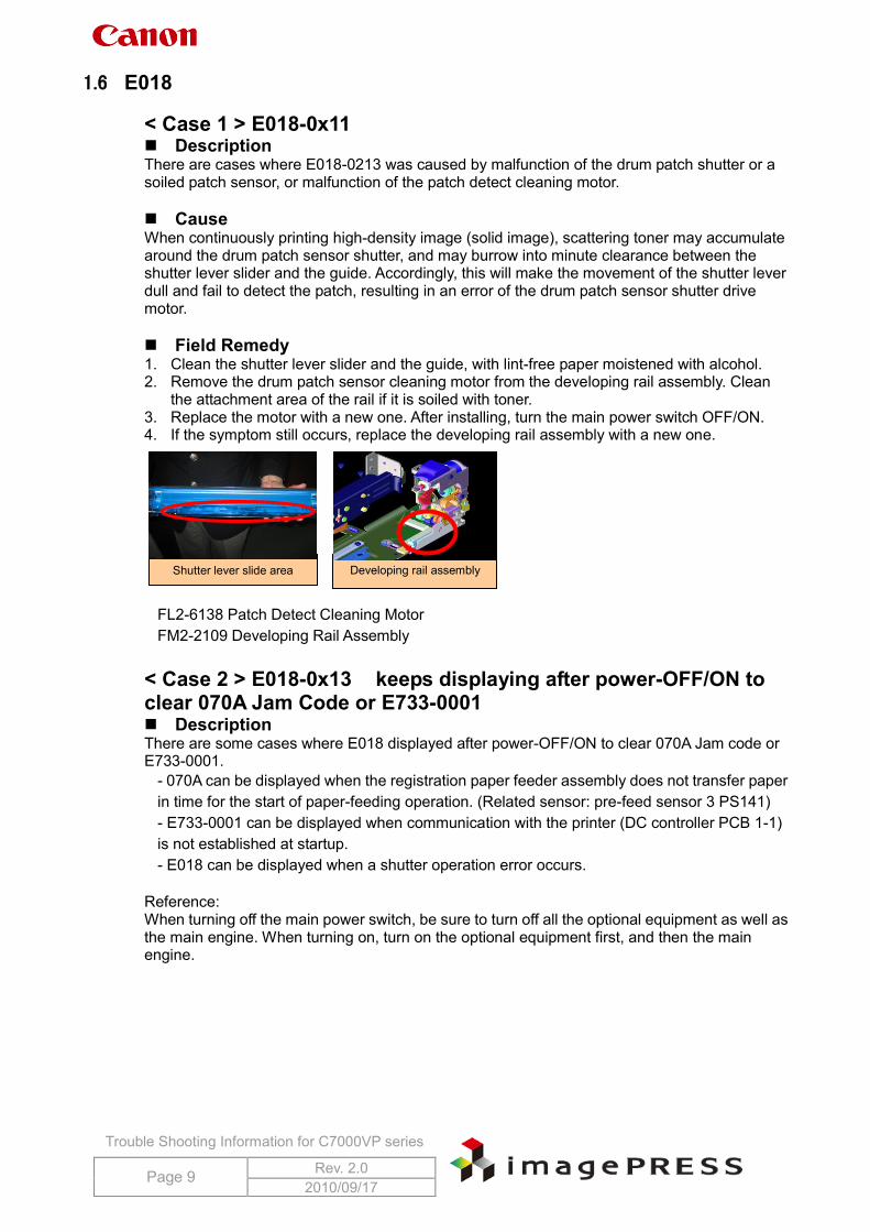
1.6 E018 < Case 1 > E018-0x11 Description There are cases where E018-0213 was caused by malfunction of the drum patch shutter or a soiled patch sensor, or malfunction of the patch detect cleaning motor. Cause When continuously printing high-density image (solid image), scattering toner may accumulate around the drum patch sensor shutter, and may burrow into minute clearance between the shutter lever slider and the guide. Accordingly, this will make the movement of the shutter lever dull and fail to detect the patch, resulting in an error of the drum patch sensor shutter drive motor. Field Remedy 1. Clean the shutter lever slider and the guide, with lint-free paper moistened with alcohol. 2. Remove the drum patch sensor cleaning motor from the developing rail assembly. Clean
the attachment area of the rail if it is soiled with toner. 3. Replace the motor with a new one. After installing, turn the main power switch OFF/ON. 4. If the symptom still occurs, replace the developing rail assembly with a new one.
FL2-6138 Patch Detect Cleaning Motor FM2-2109 Developing Rail Assembly
< Case 2 > E018-0x13 keeps displaying after power-OFF/ON to clear 070A Jam Code or E733-0001 Description There are some cases where E018 displayed after power-OFF/ON to clear 070A Jam code or E733-0001.
- 070A can be displayed when the registration paper feeder assembly does not transfer paper in time for the start of paper-feeding operation. (Related sensor: pre-feed sensor 3 PS141) - E733-0001 can be displayed when communication with the printer (DC controller PCB 1-1) is not established at startup. - E018 can be displayed when a shutter operation error occurs.
Reference: When turning off the main power switch, be sure to turn off all the optional equipment as well as the main engine. When turning on, turn on the optional equipment first, and then the main engine.
Shutter lever slide area Developing rail assembly
Trouble Shooting Information for C7000VP series
Page 10 Rev. 2.0 2010/09/17
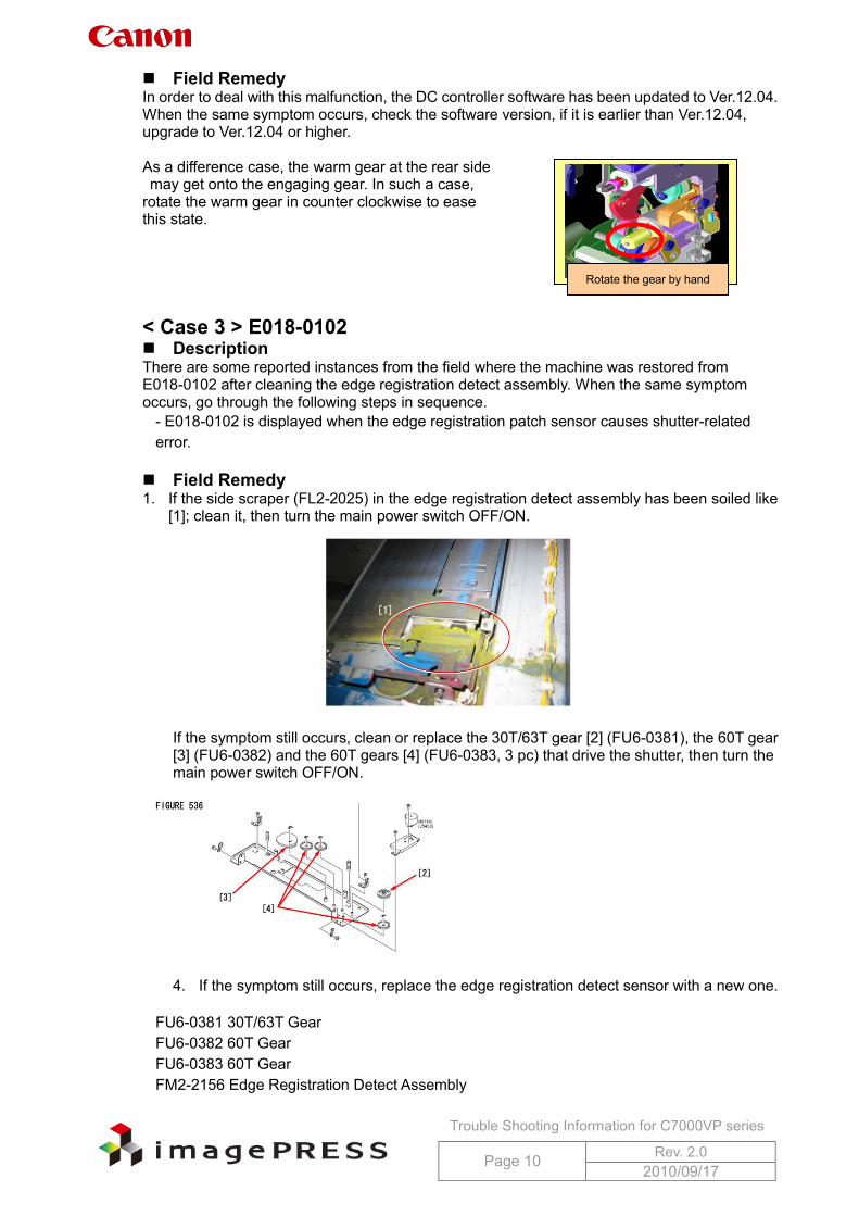
Field Remedy In order to deal with this malfunction, the DC controller software has been updated to Ver.12.04. When the same symptom occurs, check the software version, if it is earlier than Ver.12.04, upgrade to Ver.12.04 or higher. As a difference case, the warm gear at the rear side may get onto the engaging gear. In such a case, rotate the warm gear in counter clockwise to ease this state. < Case 3 > E018-0102 Description There are some reported instances from the field where the machine was restored from E018-0102 after cleaning the edge registration detect assembly. When the same symptom occurs, go through the following steps in sequence.
- E018-0102 is displayed when the edge registration patch sensor causes shutter-related error.
Field Remedy 1. If the side scraper (FL2-2025) in the edge registration detect assembly has been soiled like
[1]; clean it, then turn the main power switch OFF/ON.
If the symptom still occurs, clean or replace the 30T/63T gear [2] (FU6-0381), the 60T gear [3] (FU6-0382) and the 60T gears [4] (FU6-0383, 3 pc) that drive the shutter, then turn the main power switch OFF/ON.
4. If the symptom still occurs, replace the edge registration detect sensor with a new one.
FU6-0381 30T/63T Gear FU6-0382 60T Gear FU6-0383 60T Gear FM2-2156 Edge Registration Detect Assembly
Rotate the gear by hand
Trouble Shooting Information for C7000VP series
Page 11 Rev. 2.0 2010/09/17
1.7 E061-0181
Description There are some reported instances from the field that E061-0181 was solved by replacing the P-kit drawer assembly (FM2-2079) with a new one, not by replacing the primary corona assembly. In this field case, service mode COPIER > Display > V00 showed 905V and VFF showed 802V. Reference: The difference in voltage between V00 and VFF normally falls in the range between 400V and 500V.
- E061-0181 is a low laser power error, and can be displayed when the difference in voltage between VD and VL at the maximum potential control laser power output is 200V or lower. The meaning of the second digit of detail code is as follows: 1= yellow, 2=magenta, 3= cyan, and 4= black.
Cause Since the spring terminal of the H.V. cable to which grid bias is applied was deformed, unexpected amount of electrical charge was carried, causing the error code. Field Remedy Perform the following Steps 1 though 5, which the service manual describes, if the symptom still recurs, perform Step 6. 1. Clean the dust-proof glass. 2. Re-fit the drum unit. Note: Be sure to connect the connectors of the potential sensor and the pre-exposure lamp.
5. In service mode > COPIER > Display > DPOT, check the values of V00-Y (M/C/K) through VFF-Y (M/C/K). If those values are nearly same, the laser does not go on. In this case, check the connection of the video cable.
6. Re-fit the primary corona assembly. 7. Replace the following parts. Potential sensor Laser scanner unit Primary corona assembly 8. Check the spring terminal of the H.V. cable of a trouble P-kit for deformation or
disconnection; if there is a problem, replace the drawer connector with a new one.
FM2-2079 P-Kit Drawer Assembly FM3-4189 Primary Corona Assembly FM2-9295 Potential Measuring Assembly FM2-4887 Scanner Assembly
1.8 E062-0300 There are some reported instances from the field where E062-0300 occurred because of a not securely fitted connector of the Process Unit Driver PCB.
Trouble Shooting Information for C7000VP series
Page 12 Rev. 2.0 2010/09/17
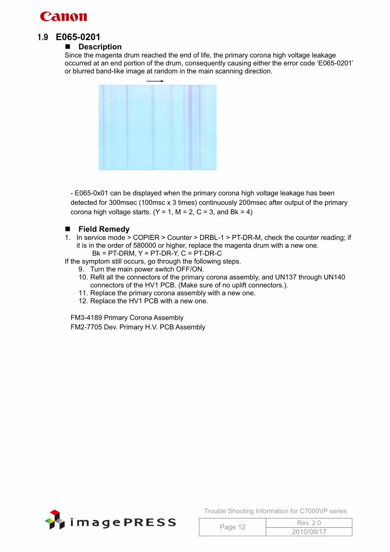
1.9 E065-0201 Description Since the magenta drum reached the end of life, the primary corona high voltage leakage occurred at an end portion of the drum, consequently causing either the error code ‘E065-0201’ or blurred band-like image at random in the main scanning direction.
- E065-0x01 can be displayed when the primary corona high voltage leakage has been detected for 300msec (100msc x 3 times) continuously 200msec after output of the primary corona high voltage starts. (Y = 1, M = 2, C = 3, and Bk = 4)
Field Remedy 1. In service mode > COPIER > Counter > DRBL-1 > PT-DR-M, check the counter reading; if
it is in the order of 580000 or higher, replace the magenta drum with a new one. Bk = PT-DRM, Y = PT-DR-Y, C = PT-DR-C
If the symptom still occurs, go through the following steps. 9. Turn the main power switch OFF/ON. 10. Refit all the connectors of the primary corona assembly, and UN137 through UN140
connectors of the HV1 PCB. (Make sure of no uplift connectors.). 11. Replace the primary corona assembly with a new one. 12. Replace the HV1 PCB with a new one.
FM3-4189 Primary Corona Assembly FM2-7705 Dev. Primary H.V. PCB Assembly
Trouble Shooting Information for C7000VP series
Page 13 Rev. 2.0 2010/09/17
1.10 E077-0001 Description There are some reported instances from the field where, during initial rotation after clearing a jam at the main station and closing the front cover, the error code ‘E077-0001’ was displayed.
- E077-0001 displays when engagement/disengagement of the secondary transfer external roller cannot be completed within 5 sec.
Cause Since the lever (B-E1) on the Registration Paper feeder assembly (at the main station) is not securely locked, engagement/disengagement of the secondary transfer external roller cannot be completed normally. Field Remedy 1. If the same error code appears when the front cover is closed after work, check to see if the
lever (B-E1) is shifted to the locking position; if not, shift it again. If the lever is in the locking position, go to Step2. Note: If the lever is locked at the wrong position, the lower portion of the cover may not be fitted completely although the upper portion does so. After the front cover is closed, be sure to make sure that both upper and lower portions fit completely to the main body. 13. Refit the connector of the secondary transfer pressure release motor (M184). 14. If the symptom still occurs, replace the secondary transfer pressure release motor with
a new one.
FK2-3124 Stepping DC Motor
1.11 E078-0001 Description There are some reported instances from the field where E078-0001 was displayed because the ITB cleaner motor did not rotate. When the same symptom occurs, perform the following field remedy.
- E078-0001 can be displayed when the phase lock signal is not detected for 500msec (100msec x 5 times) continuously even if 2 sec or more have passed since the start of the ITB cleaner motor. Field Remedy 1. Re-fit the connector at J5229S or J5229P on the ITB cleaner motor.
15. Re-fit the connectors at J1340 and J1337 on the I.T.B. Driver PCB Assembly (L). 16. If the symptom still occurs, replace the ITB cleaner motor with a new one.
Reference: The connector at J1046 on the DC Controller PCB 1-1 is also related to the aforementioned error code.
FK2-2725 Brushless Motor FM2-7690 I.T.B. Driver PCB Assembly, L
Trouble Shooting Information for C7000VP series
Page 14 Rev. 2.0 2010/09/17
1.12 E202-0001 Description There are some reported instances from the field where, upon installation of the cooling fan for DADF-R1, a harness extending from the fan was pinched and the fuse on the Interface PCB had an open-circuit, causing the error code E202-0001.
- E202-0001 can be displayed when an error is found during the forward trip of the HP search. The possible cause of this error is a fault in the scanner HP sensor, the scanner motor or the reader controller PCB. Field Remedy 1. When the same symptom occurs, check if the harness of the cooling fan (front/rear) has
been pinched. 2. If the harness has been pinched, suspect removal of harness covering and replace the fan
with a new one. Refer to Appendix 2 ‘Fan installation procedure’. 3. If the symptom still occurs, suspect an open-circuit of fuse on the Interface PCB and
replace the PCB with a new one.
FL2-3427 Front Fan FL2-3426 Rear Fan FM2-4662 Interface PCB Assembly
Trouble Shooting Information for C7000VP series
Page 15 Rev. 2.0 2010/09/17
1.13 E260-2000, E260-0002, E227-0001 Description At the time of installation, there are some cases where multiple error codes such as E260-2000, E260-0002, or E227-0001 occurred after the operation as follows. For the purpose of toner supply, the setting of ‘AINR-OFF’ was changed to ‘1’ with the front door open and then the door switch tool was inserted into the door switch unit. The error code was indicated, so the front door was closed, however, even the fan did not run. The following events were confirmed. a. The fan was running with the front door open. b. With the front door open, 24V output was confirmed at 24V power supply1 but no output was at 24V power supply2. However, after opening the front door of the sub station and closing the main station’s door, 24V output was confirmed.
- E260-2000: 5V, 13V power supply error. - E260-0002: When activation of 24V-2 cannot be detected even when 1 sec elapsed after the relay and remote signal was turned on. - E227-0001: When activation of 24V-1 cannot be detected even when 1 sec elapsed after the relay and remote signal was turned on.
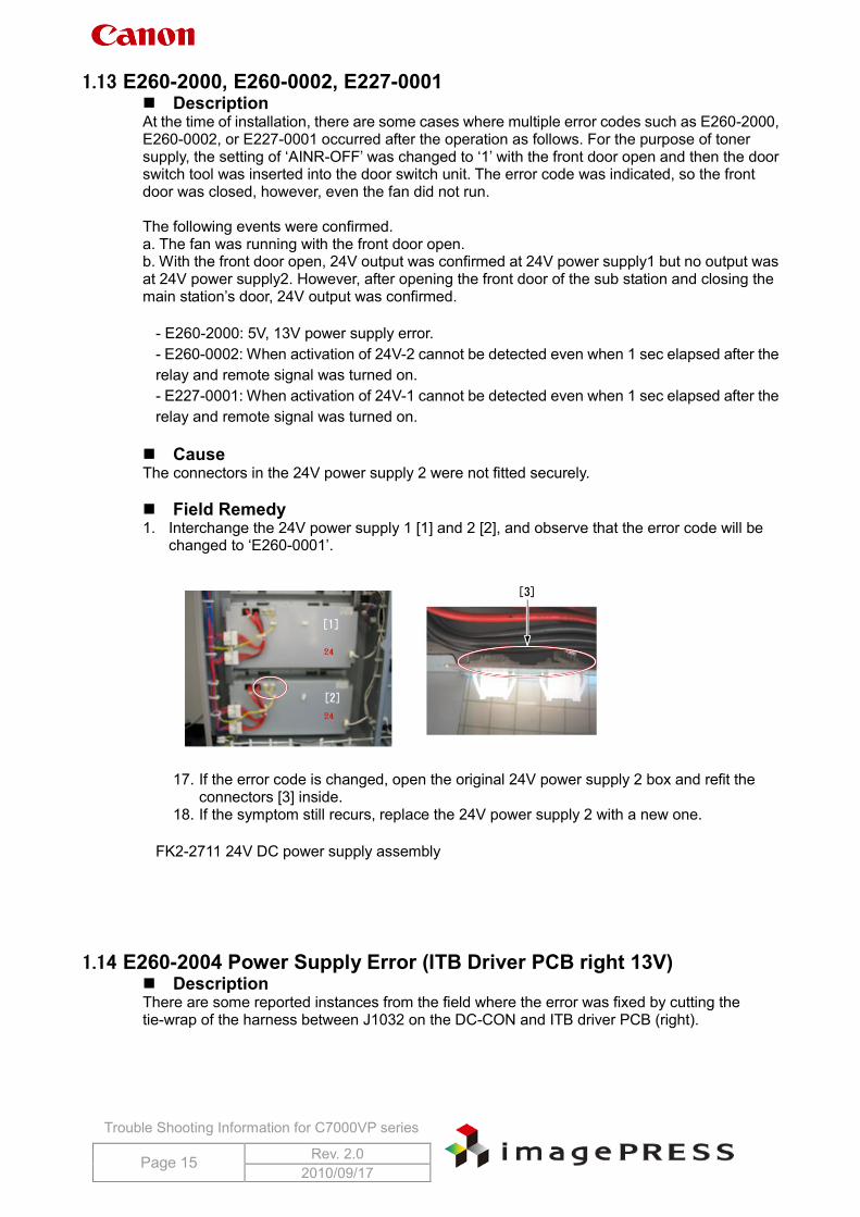
Cause The connectors in the 24V power supply 2 were not fitted securely. Field Remedy 1. Interchange the 24V power supply 1 [1] and 2 [2], and observe that the error code will be
changed to ‘E260-0001’.
17. If the error code is changed, open the original 24V power supply 2 box and refit the connectors [3] inside.
18. If the symptom still recurs, replace the 24V power supply 2 with a new one.
FK2-2711 24V DC power supply assembly
1.14 E260-2004 Power Supply Error (ITB Driver PCB right 13V) Description There are some reported instances from the field where the error was fixed by cutting the tie-wrap of the harness between J1032 on the DC-CON and ITB driver PCB (right).
Trouble Shooting Information for C7000VP series
Page 16 Rev. 2.0 2010/09/17
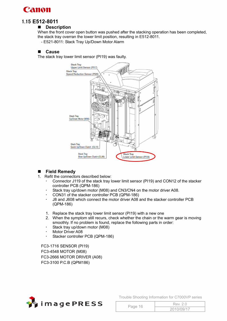
1.15 E512-8011 Description When the front cover open button was pushed after the stacking operation has been completed, the stack tray overran the lower limit position, resulting in E512-8011.
- E521-8011: Stack Tray Up/Down Motor Alarm Cause The stack tray lower limit sensor (PI19) was faulty.
Field Remedy 1. Refit the connectors described below:
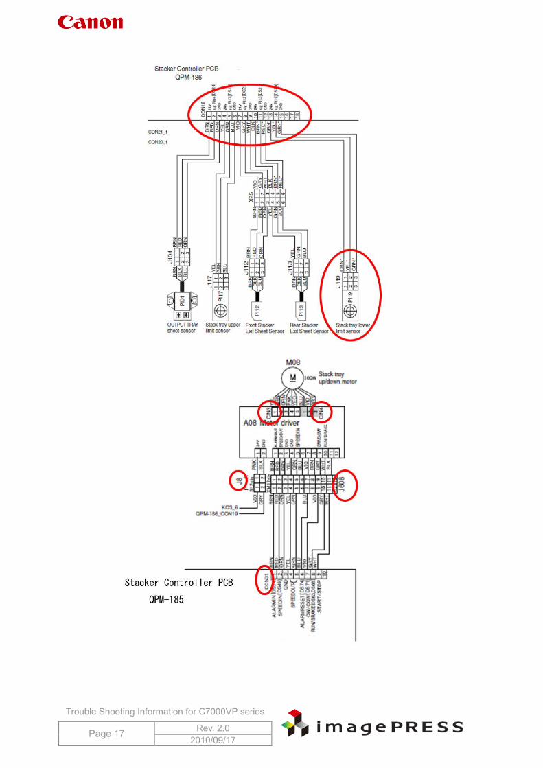
Connector J119 of the stack tray lower limit sensor (PI19) and CON12 of the stacker controller PCB (QPM-186)
Stack tray up/down motor (M08) and CN3/CN4 on the motor driver A08. CON31 of the stacker controller PCB (QPM-186) J8 and J608 which connect the motor driver A08 and the stacker controller PCB
(QPM-186)
1. Replace the stack tray lower limit sensor (PI19) with a new one 2. When the symptom still recurs, check whether the chain or the warm gear is moving
smoothly. If no problem is found, replace the following parts in order: Stack tray up/down motor (M08) Motor Driver A08 Stacker controller PCB (QPM-186)
FC3-1716 SENSOR (PI19) FC3-4548 MOTOR (M08) FC3-2666 MOTOR DRIVER (A08) FC3-3100 P.C.B (QPM186)
Trouble Shooting Information for C7000VP series
Page 17 Rev. 2.0 2010/09/17
Trouble Shooting Information for C7000VP series
Page 18 Rev. 2.0 2010/09/17
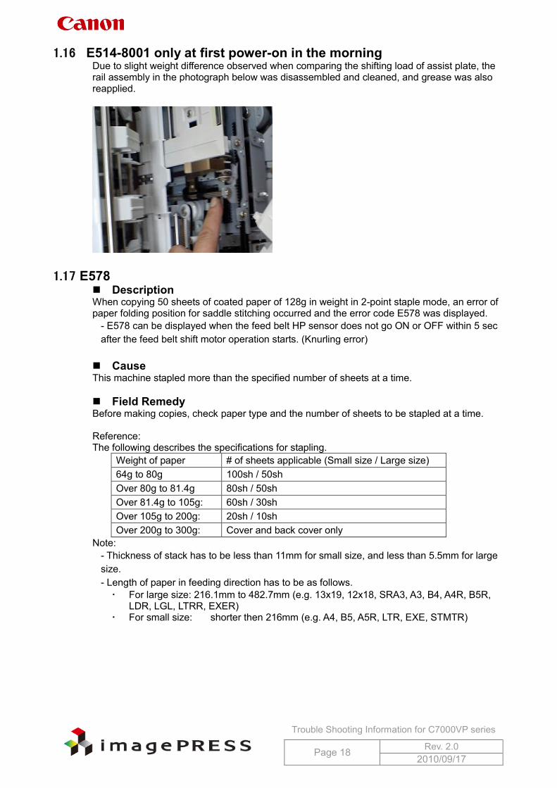
1.16 E514-8001 only at first power-on in the morning Due to slight weight difference observed when comparing the shifting load of assist plate, the rail assembly in the photograph below was disassembled and cleaned, and grease was also reapplied.
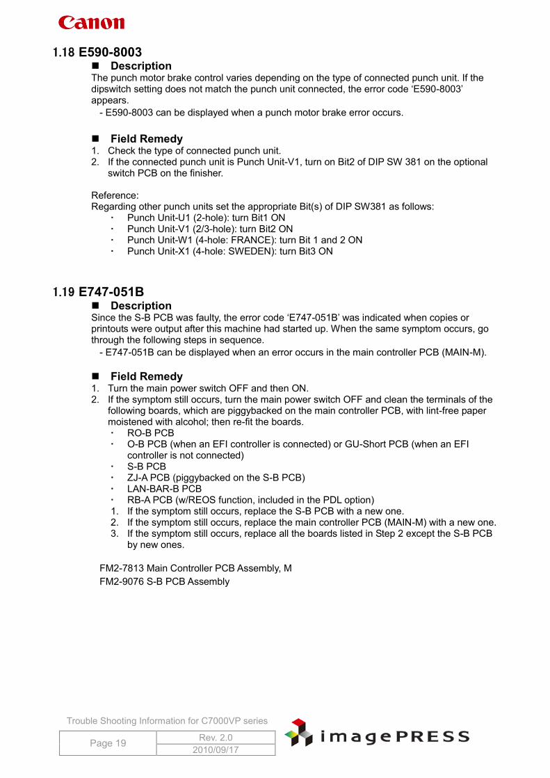
1.17 E578 Description When copying 50 sheets of coated paper of 128g in weight in 2-point staple mode, an error of paper folding position for saddle stitching occurred and the error code E578 was displayed.
- E578 can be displayed when the feed belt HP sensor does not go ON or OFF within 5 sec after the feed belt shift motor operation starts. (Knurling error)
Cause This machine stapled more than the specified number of sheets at a time. Field Remedy Before making copies, check paper type and the number of sheets to be stapled at a time. Reference: The following describes the specifications for stapling.
Weight of paper # of sheets applicable (Small size / Large size) 64g to 80g 100sh / 50sh Over 80g to 81.4g 80sh / 50sh Over 81.4g to 105g: 60sh / 30sh Over 105g to 200g: 20sh / 10sh Over 200g to 300g: Cover and back cover only
Note: - Thickness of stack has to be less than 11mm for small size, and less than 5.5mm for large size. - Length of paper in feeding direction has to be as follows. For large size: 216.1mm to 482.7mm (e.g. 13x19, 12x18, SRA3, A3, B4, A4R, B5R,
LDR, LGL, LTRR, EXER) For small size: shorter then 216mm (e.g. A4, B5, A5R, LTR, EXE, STMTR)
Trouble Shooting Information for C7000VP series
Page 19 Rev. 2.0 2010/09/17
1.18 E590-8003 Description The punch motor brake control varies depending on the type of connected punch unit. If the dipswitch setting does not match the punch unit connected, the error code ‘E590-8003’ appears.
- E590-8003 can be displayed when a punch motor brake error occurs. Field Remedy 1. Check the type of connected punch unit. 2. If the connected punch unit is Punch Unit-V1, turn on Bit2 of DIP SW 381 on the optional
switch PCB on the finisher. Reference: Regarding other punch units set the appropriate Bit(s) of DIP SW381 as follows:
Punch Unit-U1 (2-hole): turn Bit1 ON Punch Unit-V1 (2/3-hole): turn Bit2 ON Punch Unit-W1 (4-hole: FRANCE): turn Bit 1 and 2 ON Punch Unit-X1 (4-hole: SWEDEN): turn Bit3 ON
1.19 E747-051B Description Since the S-B PCB was faulty, the error code ‘E747-051B’ was indicated when copies or printouts were output after this machine had started up. When the same symptom occurs, go through the following steps in sequence.
- E747-051B can be displayed when an error occurs in the main controller PCB (MAIN-M). Field Remedy 1. Turn the main power switch OFF and then ON. 2. If the symptom still occurs, turn the main power switch OFF and clean the terminals of the
following boards, which are piggybacked on the main controller PCB, with lint-free paper moistened with alcohol; then re-fit the boards. RO-B PCB O-B PCB (when an EFI controller is connected) or GU-Short PCB (when an EFI
controller is not connected) S-B PCB ZJ-A PCB (piggybacked on the S-B PCB) LAN-BAR-B PCB RB-A PCB (w/REOS function, included in the PDL option) 1. If the symptom still occurs, replace the S-B PCB with a new one. 2. If the symptom still occurs, replace the main controller PCB (MAIN-M) with a new one. 3. If the symptom still occurs, replace all the boards listed in Step 2 except the S-B PCB
by new ones.
FM2-7813 Main Controller PCB Assembly, M FM2-9076 S-B PCB Assembly
Trouble Shooting Information for C7000VP series
Page 20 Rev. 2.0 2010/09/17
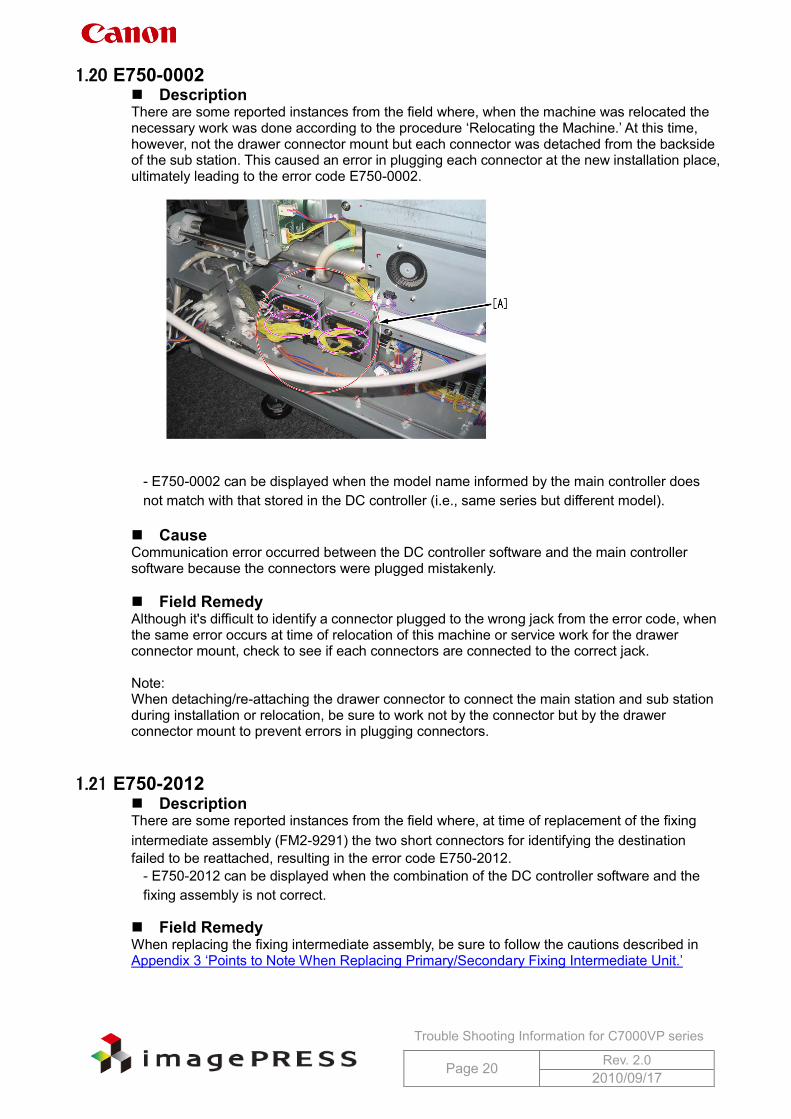
1.20 E750-0002 Description There are some reported instances from the field where, when the machine was relocated the necessary work was done according to the procedure ‘Relocating the Machine.’ At this time, however, not the drawer connector mount but each connector was detached from the backside of the sub station. This caused an error in plugging each connector at the new installation place, ultimately leading to the error code E750-0002.
- E750-0002 can be displayed when the model name informed by the main controller does not match with that stored in the DC controller (i.e., same series but different model).
Cause Communication error occurred between the DC controller software and the main controller software because the connectors were plugged mistakenly. Field Remedy Although it's difficult to identify a connector plugged to the wrong jack from the error code, when the same error occurs at time of relocation of this machine or service work for the drawer connector mount, check to see if each connectors are connected to the correct jack. Note: When detaching/re-attaching the drawer connector to connect the main station and sub station during installation or relocation, be sure to work not by the connector but by the drawer connector mount to prevent errors in plugging connectors.
1.21 E750-2012 Description There are some reported instances from the field where, at time of replacement of the fixing intermediate assembly (FM2-9291) the two short connectors for identifying the destination failed to be reattached, resulting in the error code E750-2012.
- E750-2012 can be displayed when the combination of the DC controller software and the fixing assembly is not correct.
Field Remedy When replacing the fixing intermediate assembly, be sure to follow the cautions described in Appendix 3 ‘Points to Note When Replacing Primary/Secondary Fixing Intermediate Unit.’
Trouble Shooting Information for C7000VP series
Page 21 Rev. 2.0 2010/09/17
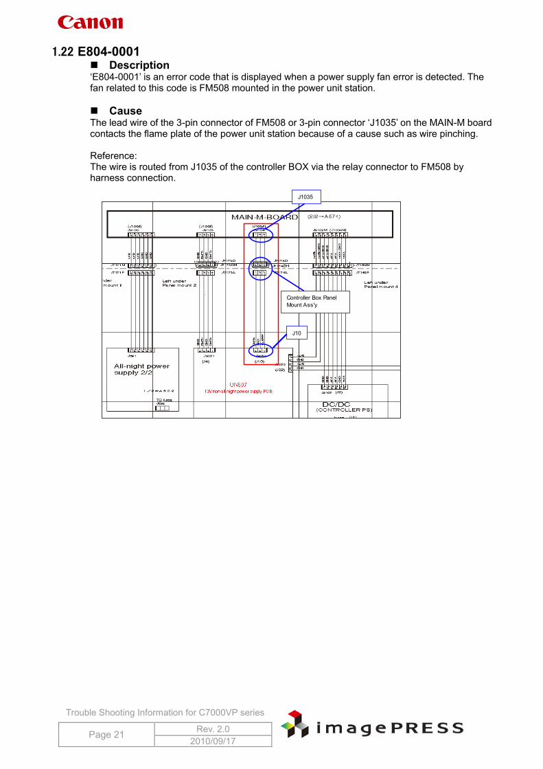
1.22 E804-0001 Description ‘E804-0001’ is an error code that is displayed when a power supply fan error is detected. The fan related to this code is FM508 mounted in the power unit station. Cause The lead wire of the 3-pin connector of FM508 or 3-pin connector ‘J1035’ on the MAIN-M board contacts the flame plate of the power unit station because of a cause such as wire pinching. Reference: The wire is routed from J1035 of the controller BOX via the relay connector to FM508 by harness connection.
J1035
Controller Box PanelMount Ass'y
J10
Trouble Shooting Information for C7000VP series
Page 22 Rev. 2.0 2010/09/17
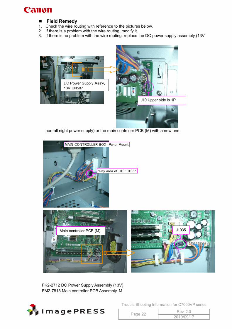
Field Remedy 1. Check the wire routing with reference to the pictures below. 2. If there is a problem with the wire routing, modify it. 3. If there is no problem with the wire routing, replace the DC power supply assembly (13V
non-all night power supply) or the main controller PCB (M) with a new one.
FK2-2712 DC Power Supply Assembly (13V) FM2-7813 Main controller PCB Assembly, M
MAIN CONTROLLER BOX Panel Mount
relay area of J10-J1035
J1035Main controller PCB (M)
DC Power Supply Ass'y,13V UN507
J10 Upper side is 1P
Trouble Shooting Information for C7000VP series
Page 23 Rev. 2.0 2010/09/17
1.23 E805-0404 Description There are some reported instances from the field where the machine was restored from the error code E805-0404 after replacement of the fixing/feeder driver assembly (FM2-2260).
- E805-0404 can be displayed when the pre-fixing feed rear left fan (FM137) error occurs. FM137 is used to attract paper to the pre-fixing feed belt.
Note: When this error code occurs, after taking the appropriate remedy, turn the main power switch ON and then execute the following service mode: service mode > COPIER > Function > CLEAR > ERR. After that, turn the main power switch OFF/ON so that the error code will be cleared. Be sure to turn the switch of the pick-up/delivery optional equipment ON first, and then the main engine. Otherwise, the machine fails to recognize the optional equipment. Reference: The error codes that require the error clear operation are as follows: E000, E001, E002, E003, E004, E013, E717, and E719. Field Remedy 1. Re-fit J1557 connector of the fixing/feeder driver PCB. 2. Re-fit the connectors J5449, J7405, and J7400 between the fan FM137 and J1557 of the
fixing/feeder driver PCB. 3. If the symptom still occurs, replace the fixing/feeder driver PCB with a now one.
FM2-2260 Fixing/feeder Driver PCB Assembly
Trouble Shooting Information for C7000VP series
Page 24 Rev. 2.0 2010/09/17
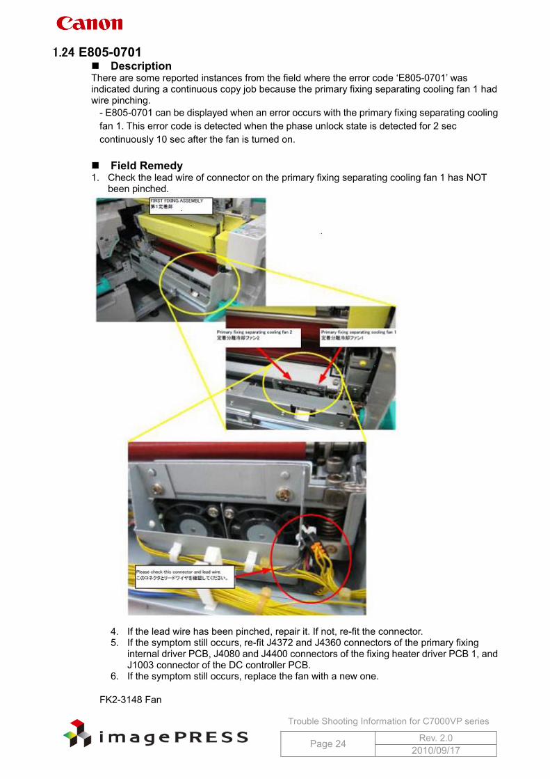
1.24 E805-0701 Description There are some reported instances from the field where the error code ‘E805-0701’ was indicated during a continuous copy job because the primary fixing separating cooling fan 1 had wire pinching.
- E805-0701 can be displayed when an error occurs with the primary fixing separating cooling fan 1. This error code is detected when the phase unlock state is detected for 2 sec continuously 10 sec after the fan is turned on. Field Remedy 1. Check the lead wire of connector on the primary fixing separating cooling fan 1 has NOT
been pinched.
4. If the lead wire has been pinched, repair it. If not, re-fit the connector. 5. If the symptom still occurs, re-fit J4372 and J4360 connectors of the primary fixing
internal driver PCB, J4080 and J4400 connectors of the fixing heater driver PCB 1, and J1003 connector of the DC controller PCB.
6. If the symptom still occurs, replace the fan with a new one.
FK2-3148 Fan
Trouble Shooting Information for C7000VP series
Page 25 Rev. 2.0 2010/09/17
1.25 E822-0903 Description There are some reported instances from the field where the error code ‘E822-0903’ was indicated because a communication error occurred between the fixing duplex feed PCB and the DC controller PCB 1-2 on the main station due to poor contact of the fixing duplexing drawer.
- E822-0903 can be displayed when the tandem guide lower cooling fan (FM358) causes an error (sub station). Field Remedy 1. Service mode > COPIER > Function > PART-CHK > FAN > enter '84' using the numeric
keys > OK > FAN-ON > check the operation of the fan. If the fan has no problem, it will rotate for 10 sec at full speed.
2. If the fan does not rotate, re-fit the connector of the fan (FM358) to correct such a problem as poor contact.
3. If the symptom still occurs, re-fit the fixing duplexing drawer connectors (fitted on the front and back sides).
4. If the symptom still occurs, re-fit J4106 and J4070 connectors of the fixing duplex feed PCB, and J1072 connector of the DC controller PCB 1-2.
5. If the symptom still occurs, replace the fan (FM358), the fixing duplex feed PCB, the DC controller PCB 1-2 with new ones in this order.
FK2-3100 FAN FM2-7700 Fixing Duplex Feed PCB Assembly FM2-7686 DC Controller PCB 1-2 Assembly
Trouble Shooting Information for C7000VP series
Page 26 Rev. 2.0 2010/09/17
1.26 E020 E020-0x81 Error Description: Lower limit error in light intensity on drum base (reflecting light intensity from the drum surface) * COPIER > Display > DENS > P-B-P-Y/M/C/K is less than 150. Cause of occurrence (Highly possible): Soil on the ATR sensor [*1] Cause of occurrence (Low possible): Faulty pressure for developing assembly Broken wire of ATR sensor Damaged ATR sensor Malfunction of ATR patch detection shutter E020-0x82 Error Description: Lower limit error in current passed to the sensor while the patch sensor LED is off * COPIER > Display > DENS > P-D-P-Y/M/C/K is 30 or less. Cause of occurrence (Highly possible): Broken wire of ATR sensor Damaged ATR sensor E020-0x84 Error Description: Fault at sampling drum base * A difference between the values in service mode > COPIER > Display > DENS > P-B-P-Y/M/C/K and P-D-P-Y/M/C/K is 30 or less. Cause of occurrence (Highly possible): Soil on the ATR sensor [*1] Cause of occurrence (Low possible): Faulty pressure for developing assembly Broken wire of ATR sensor Damaged ATR sensor Malfunction of ATR patch detection shutter E020-0x85 Error Description: Fault at sampling 1 in patch image * A difference between the values in service mode > COPIER > Display > DENS > DENS-S-Y/M/C/K and P-D-P-Y/M/C/K is 30 or less. Cause of occurrence (Highly possible): Soil on the ATR sensor [*1] Cause of occurrence (Low possible): Image density is too high. Faulty pressure for developing assembly Broken wire of ATR sensor Damaged ATR sensor Malfunction of ATR patch detection shutter E020-0x86 Error Description: Fault at sampling 2 in patch image * A difference between the values in service mode > COPIER > Display > DENS > DENS-S-Y/M/C/K and P-B-P-Y/M/C/K is 30 or less. Cause of occurrence (Highly possible): Image density is too low. [*2] Cause of occurrence (Low possible): Soil on the ATR sensor Faulty pressure for developing assembly Broken wire of ATR sensor Damaged ATR sensor Malfunction of ATR patch detection shutter
Trouble Shooting Information for C7000VP series
Page 27 Rev. 2.0 2010/09/17
E020-0x87 Error Description: Upper limit error 2 in current passed to the sensor while the patch sensor LED is off * COPIER > Display > DENS > P-D-P-Y/M/C/K is 930 or more. Cause of occurrence (Highly possible): Damaged ATR sensor E020-0xC2 Error Description: Error in variation of sampling value in patch image * When variation of sampling Sig values is 400 or more. Cause of occurrence (Highly possible): Tiger stripe Cause of occurrence (Low possible): Scratches on drum E020-0x90 Error Description: Lower limit error in ATR patch image density Cause of occurrence (Highly possible): Soil on the ATR sensor [*1] Cause of occurrence (Low possible): Image density is too high. Faulty pressure for developing assembly Broken wire of ATR sensor Damaged ATR sensor Malfunction of ATR patch detection shutter E020-0x91 Error Description: Upper limit error in ATR patch image density * COPIER > Display > DENS > DENS-S-Y/M/C/K is more than 880. Cause of occurrence (Highly possible): Image density is too low. [*2] Cause of occurrence (Low possible): Soil on the ATR sensor Faulty pressure for developing assembly Broken wire of ATR sensor Damaged ATR sensor Malfunction of ATR patch detection shutter E020-0x92 Error Description: Lower limit error in developer density * COPIER > Display > DENS > DENS-S-Y/M/C/K is –4% or less 3 consecutive times. Cause of occurrence (Highly possible): Image density is too low. [*2] Cause of occurrence (Low possible): Soil on the ATR sensor Faulty pressure for developing assembly Broken wire of ATR sensor Damaged ATR sensor Malfunction of ATR patch detection shutter E020-0x93 Error Description: Upper limit error in developer density * COPIER > Display > DENS > DENS-S-Y/M/C/K is +4% or more 3 consecutive times. Cause of occurrence (Highly possible): Soil on the ATR sensor [*1] Cause of occurrence (Low possible): Image density is too high. Faulty pressure for developing assembly Broken wire of ATR sensor Damaged ATR sensor Malfunction of ATR patch detection shutter
Trouble Shooting Information for C7000VP series
Page 28 Rev. 2.0 2010/09/17
E020-0xB0 Error Description: Lower limit error in signal value of toner density sensor * While printing, COPIER > Display > DENS > SGLL-Y/M/C/K is 64 or less for Y and 48 or less for M/C/K for 5 prints continuously (T/D ratio is too high). Cause of occurrence (Highly possible): Abnormal toner supply [*3] Cause of occurrence (Low possible): Short circuit of harness for ATR sensor Occurrence of Tiger stripe E020-0xB1 Error Description: Upper limit error in signal value of toner density sensor * While printing, COPIER > Display > DENS > SGLL-Y/M/C/K is 192 or more for Y and 126 or more for M/C/K for 5 prints continuously (T/D ratio is too low). Cause of occurrence (Highly possible): Disconnected connector of toner density sensor (or
poor contact) Cause of occurrence (Low possible): Faulty sub hopper (no toner) Damaged toner density sensor
Trouble Shooting Information for C7000VP series
Page 29 Rev. 2.0 2010/09/17
*1 Soil on the ATR sensor Field Remedy 1. Clean the ATR sensor with alcohol.
Note: Wipe the sensor in one direction more than 3 times. Do NOT wipe it back-and-forth. 7. Replace the ATR sensor with a new one.
In addition, for the purpose of preventing any future occurrence, follow the steps below. a. Service mode(Level 2) > COPIER > Adjust > DENS > HLMT-PTY/M/C/K,
Settings: If the current value is 4, change it to 9. If the current value is 9, change it to 10.
Note: Density might decrease as a negative effect. Therefore, execute the above setting value change only if soil on the sensor occurred at less than 250K intervals of periodic cleaning maintenance for ATR sensor. Or b. Shorten the interval of cleaning maintenance.
*2 Image density is too low As possible causes of low image density, soiled primary charging assembly, faulty laser, soiled dust-proof glass, faulty drum, faulty developing, and etc. are conceivable. However, faulty developing is the most likely. For this reason, check the area around the developing assembly first. Field Remedy 1. Check the area around the developing assembly.
Are there occurrences of Tiger stripe? Are there occurrences of developer overflow? If these symptoms have occurred, replace the developer after taking actions such as cleaning. 1. If there is no abnormality found at the step 1, output PG5 of the corresponding color
with density settings ‘80’ and ‘255’. Check the density and unevenness.
Trouble Shooting Information for C7000VP series
Page 30 Rev. 2.0 2010/09/17
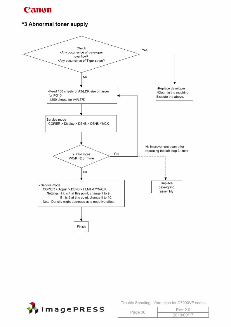
*3 Abnormal toner supply
No
Yes
No
No improvement even afterrepeating the left loop 3 times
・Feed 100 sheets of A3/LDR size or larger for PG10 (200 sheets for A4/LTR)
Service mode COPIER > Display > DENS > DENS-YMCK
Y +1or moreM/C/K +2 or more
Check・Any occurrence of developer
overflow?・Any occurrence of Tiger stripe?
Yes
・Replace developer・Clean in the machineExecute the above.
Replacedevelopingassembly
- Service mode COPIER > Adjust > DENS > HLMT-TY/M/C/K Settings: If it is 4 at this point, change it to 9. If it is 9 at this point, change it to 10. Note: Density might decrease as a negative effect.
Finish

Trouble Shooting Information for C7000VP series
Page 31 Rev. 2.0 2010/09/17
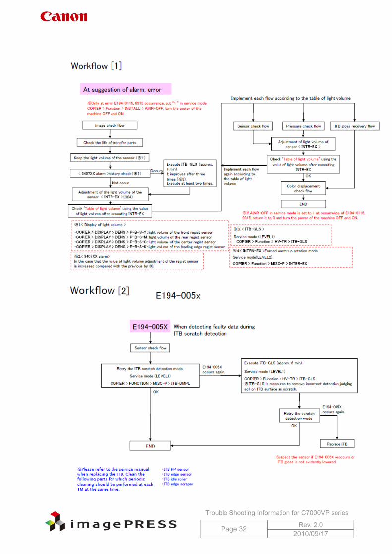
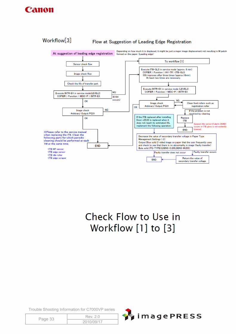
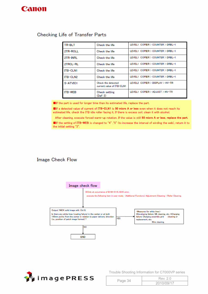
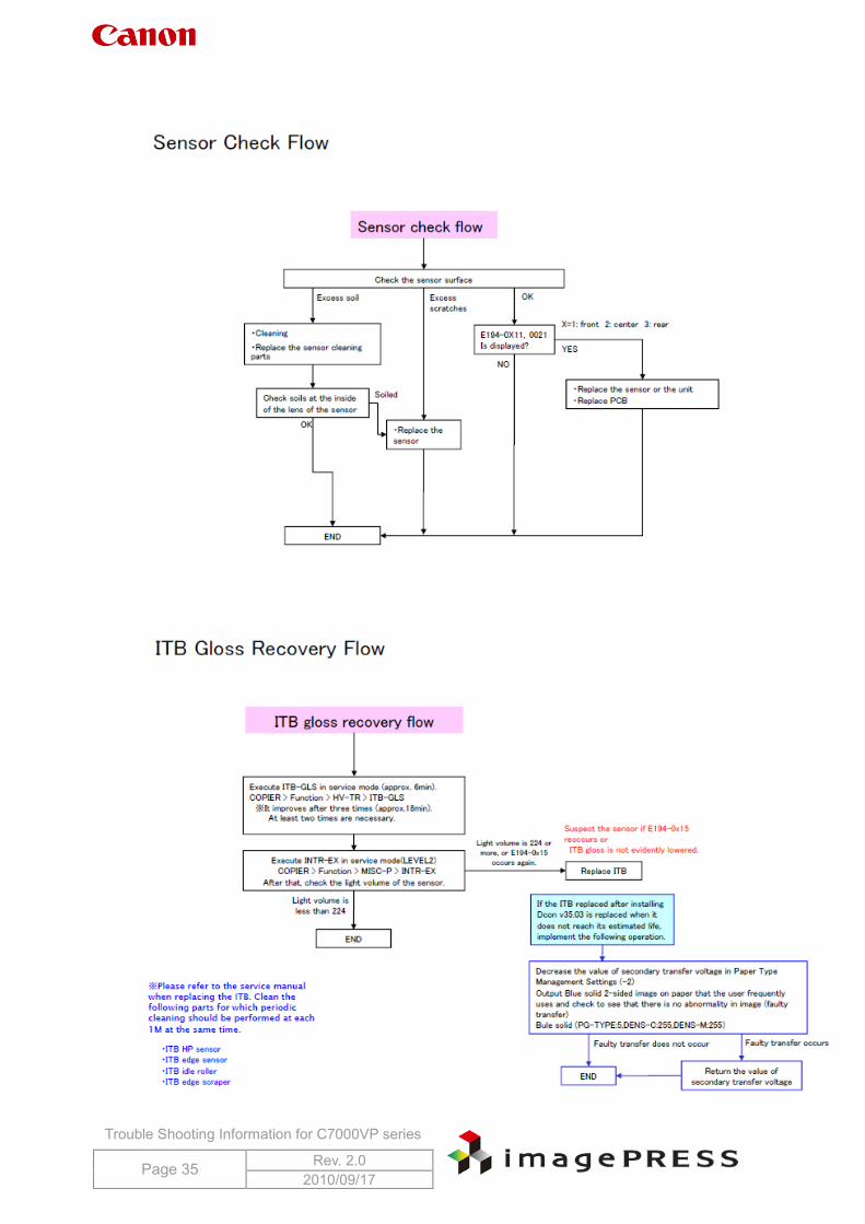
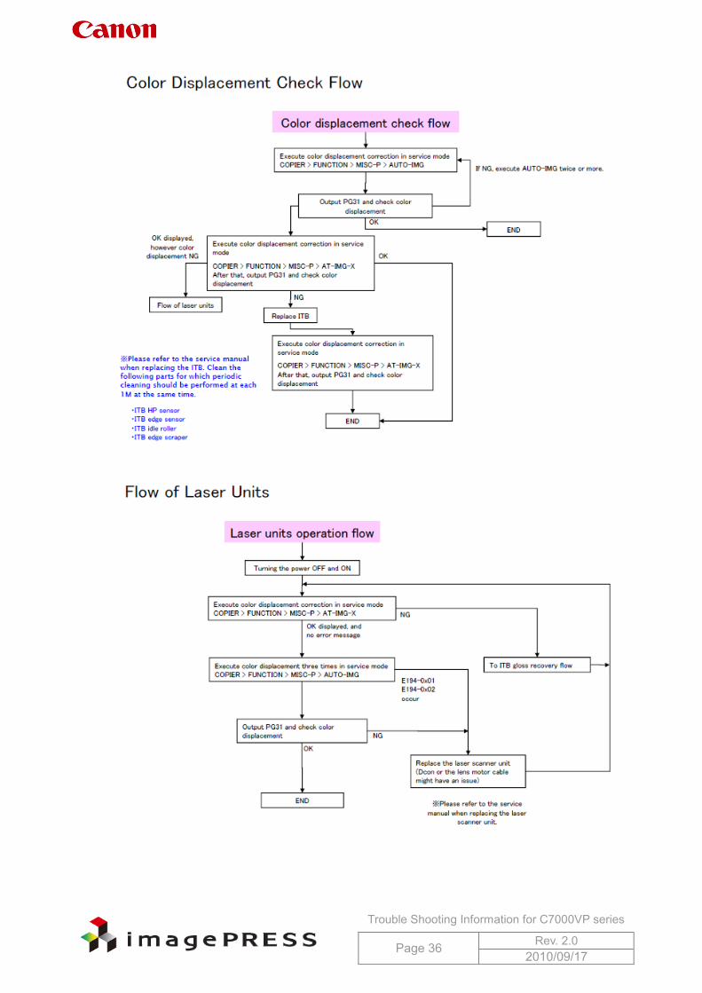
1.27 E194 and Color Registration Failure
Trouble Shooting Information for C7000VP series
Page 32 Rev. 2.0 2010/09/17
Trouble Shooting Information for C7000VP series
Page 33 Rev. 2.0 2010/09/17
Trouble Shooting Information for C7000VP series
Page 34 Rev. 2.0 2010/09/17
Trouble Shooting Information for C7000VP series
Page 35 Rev. 2.0 2010/09/17
Trouble Shooting Information for C7000VP series
Page 36 Rev. 2.0 2010/09/17
Trouble Shooting Information for C7000VP series
Page 37 Rev. 2.0 2010/09/17
Trouble Shooting Information for C7000VP series
Page 38 Rev. 2.0 2010/09/17
Trouble Shooting Information for C7000VP series
Page 39 Rev. 2.0 2010/09/17
Trouble Shooting Information for C7000VP series
Page 40 Rev. 2.0 2010/09/17
Trouble Shooting Information for C7000VP series
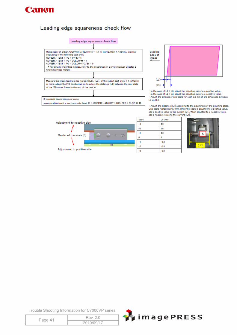
Page 41 Rev. 2.0 2010/09/17
Trouble Shooting Information for C7000VP series
Page 42 Rev. 2.0 2010/09/17
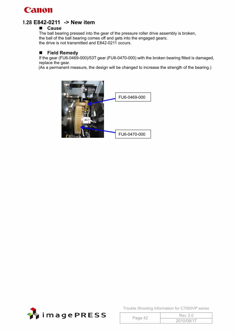
1.28 E842-0211 -> New item Cause The ball bearing pressed into the gear of the pressure roller drive assembly is broken, the ball of the ball bearing comes off and gets into the engaged gears; the drive is not transmitted and E842-0211 occurs.
Field Remedy If the gear (FU6-0469-000)/53T gear (FU6-0470-000) with the broken bearing fitted is damaged, replace the gear. (As a permanent measure, the design will be changed to increase the strength of the bearing.)
FU6-0470-000
FU6-0469-000
Trouble Shooting Information for C7000VP series
Page 43 Rev. 2.0 2010/09/17
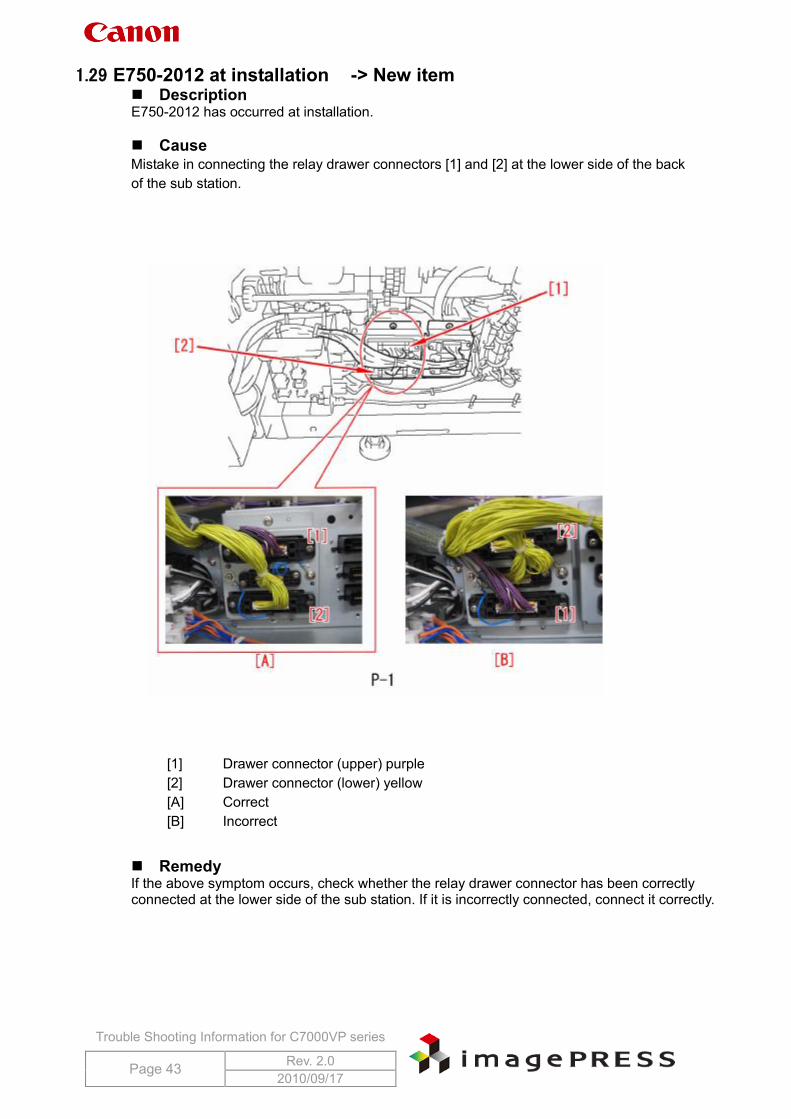
1.29 E750-2012 at installation -> New item Description E750-2012 has occurred at installation. Cause
Mistake in connecting the relay drawer connectors [1] and [2] at the lower side of the back of the sub station.
Remedy
If the above symptom occurs, check whether the relay drawer connector has been correctly connected at the lower side of the sub station. If it is incorrectly connected, connect it correctly.
[1] Drawer connector (upper) purple [2] Drawer connector (lower) yellow [A] Correct [B] Incorrect
Trouble Shooting Information for C7000VP series
Page 44 Rev. 2.0 2010/09/17
Notes at operation
Reference information
Technical Publication TP09 132
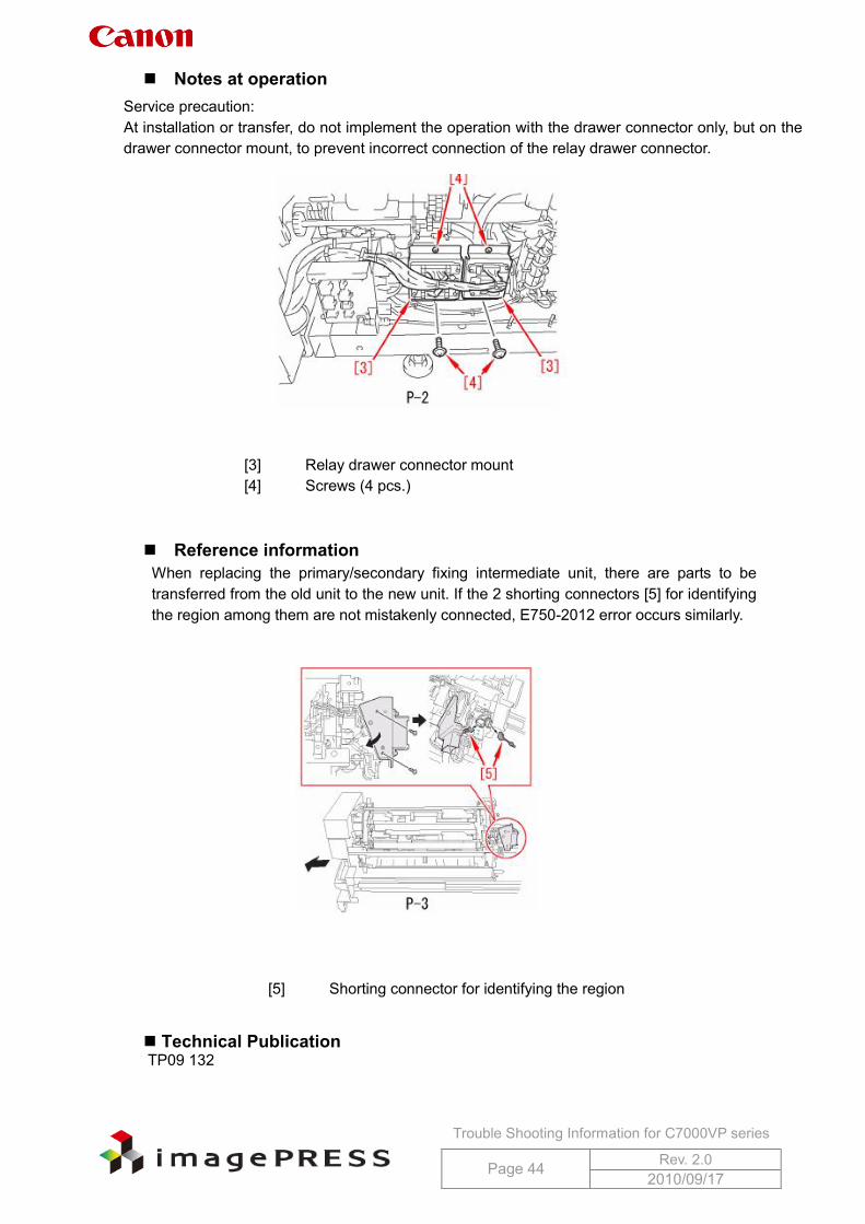
Service precaution: At installation or transfer, do not implement the operation with the drawer connector only, but on the drawer connector mount, to prevent incorrect connection of the relay drawer connector.
[3] Relay drawer connector mount [4] Screws (4 pcs.)
When replacing the primary/secondary fixing intermediate unit, there are parts to be transferred from the old unit to the new unit. If the 2 shorting connectors [5] for identifying the region among them are not mistakenly connected, E750-2012 error occurs similarly.
[5] Shorting connector for identifying the region
Trouble Shooting Information for C7000VP series
Page 45 Rev. 2.0 2010/09/17
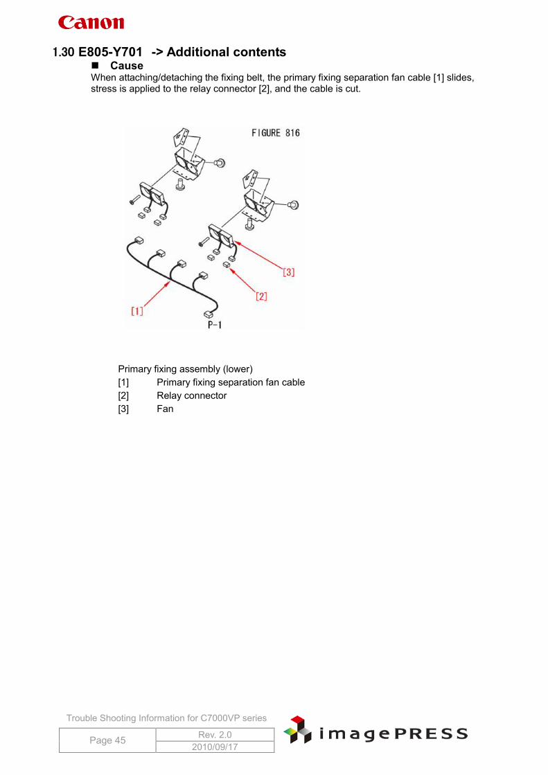
1.30 E805-Y701 -> Additional contents Cause When attaching/detaching the fixing belt, the primary fixing separation fan cable [1] slides, stress is applied to the relay connector [2], and the cable is cut.
Primary fixing assembly (lower) [1] Primary fixing separation fan cable [2] Relay connector [3] Fan
Trouble Shooting Information for C7000VP series
Page 46 Rev. 2.0 2010/09/17
Field Remedy As a measure for factory, the length of the cable is changed and the wire saddle is added.
This measure prevents stress to the end of the relay connector even when the cooling fan slides. If the issue occurs in the field, change the primary fixing separation fan cable into its new type (FM2-8765-010) and take the following measure.
.
Technical Publication TP10 068
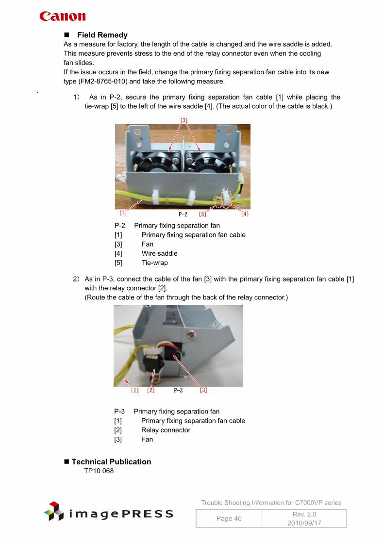
1) As in P-2, secure the primary fixing separation fan cable [1] while placing the tie-wrap [5] to the left of the wire saddle [4]. (The actual color of the cable is black.)
P-2 Primary fixing separation fan [1] Primary fixing separation fan cable [3] Fan [4] Wire saddle [5] Tie-wrap
2) As in P-3, connect the cable of the fan [3] with the primary fixing separation fan cable [1] with the relay connector [2]. (Route the cable of the fan through the back of the relay connector.)
P-3 Primary fixing separation fan [1] Primary fixing separation fan cable [2] Relay connector [3] Fan
Trouble Shooting Information for C7000VP series
Page 47 Rev. 2.0 2010/09/17
2 Operational Failure 2.1 Message prompting for toner supply
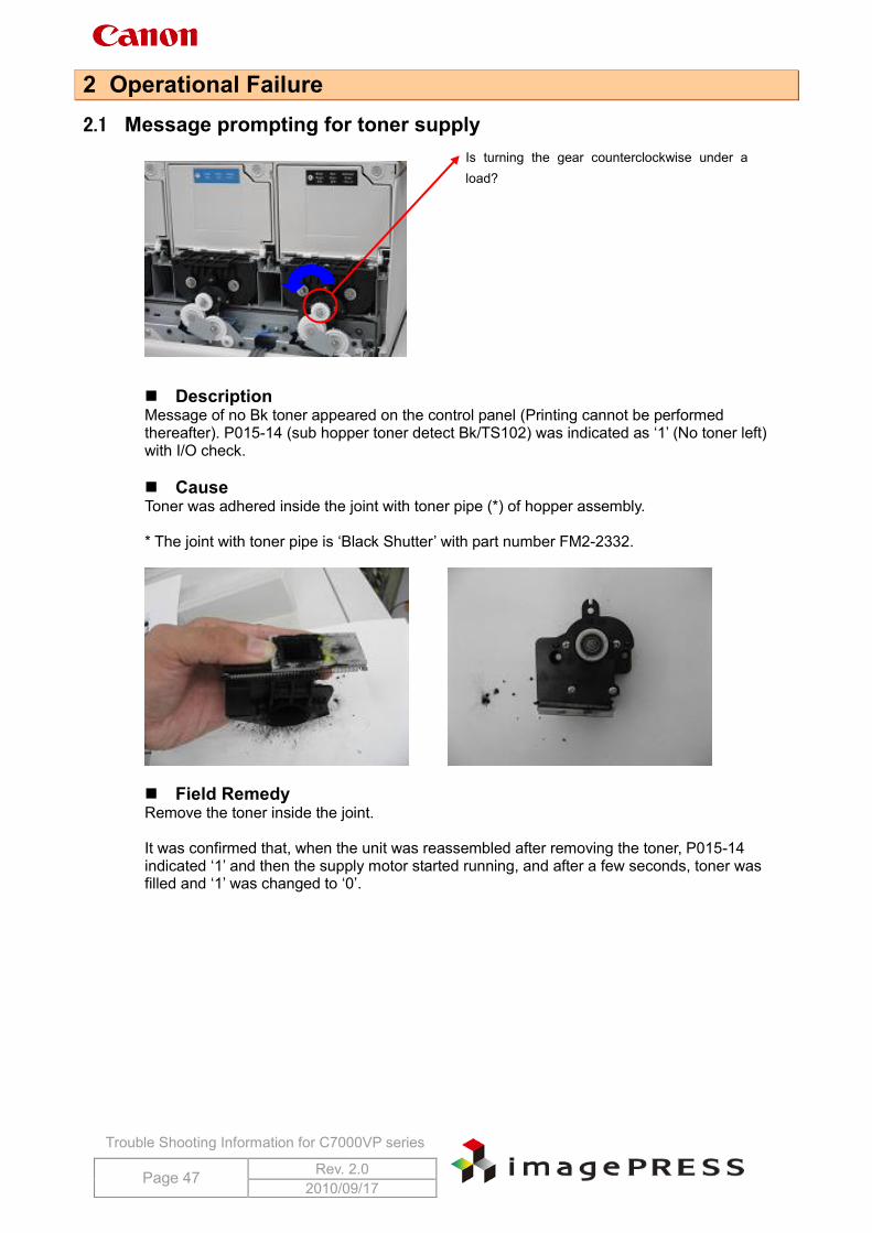
Description Message of no Bk toner appeared on the control panel (Printing cannot be performed thereafter). P015-14 (sub hopper toner detect Bk/TS102) was indicated as ‘1’ (No toner left) with I/O check. Cause Toner was adhered inside the joint with toner pipe (*) of hopper assembly. * The joint with toner pipe is ‘Black Shutter’ with part number FM2-2332.
Field Remedy Remove the toner inside the joint. It was confirmed that, when the unit was reassembled after removing the toner, P015-14 indicated ‘1’ and then the supply motor started running, and after a few seconds, toner was filled and ‘1’ was changed to ‘0’.
Is turning the gear counterclockwise under a load?
Trouble Shooting Information for C7000VP series
Page 48 Rev. 2.0 2010/09/17
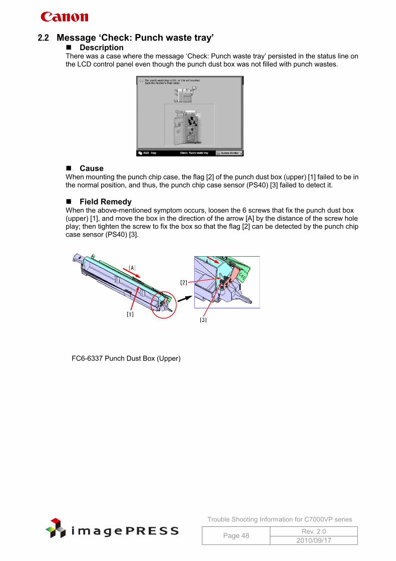
2.2 Message ‘Check: Punch waste tray’ Description There was a case where the message ‘Check: Punch waste tray’ persisted in the status line on the LCD control panel even though the punch dust box was not filled with punch wastes.
Cause When mounting the punch chip case, the flag [2] of the punch dust box (upper) [1] failed to be in the normal position, and thus, the punch chip case sensor (PS40) [3] failed to detect it. Field Remedy When the above-mentioned symptom occurs, loosen the 6 screws that fix the punch dust box (upper) [1], and move the box in the direction of the arrow [A] by the distance of the screw hole play; then tighten the screw to fix the box so that the flag [2] can be detected by the punch chip case sensor (PS40) [3].
FC6-6337 Punch Dust Box (Upper)
Trouble Shooting Information for C7000VP series
Page 49 Rev. 2.0 2010/09/17
2.3 Cannot print in spite of ‘Printing’ indication
Description When a print job was submitted from a computer, ‘printing...’ was displayed on the control panel of the host machine and each drive assembly started rotation; however, pickup and printing failed. Cause 1 The temperature of pressure roller exceeded the standard due to the installation failure of the pressure roller. As a specification, printing operation cannot proceed if the pressure roller exceeds the specified temperature. Field remedy 1 1. Check the displayed temperature in Service mode > COPIER > Display > ANALOG >
FIX2-LC / FIX2-LE. Normal temperature is around 90 deg C. 2. If the displayed temperature exceeds the 90 deg C and reaches 140 deg C or higher, check
the installation status of the pressure roller. In the actual example, it displayed 143 deg C. 3. If there is a installation failure found such as the pressure roller comes off from the shaft
support etc., reinstall it. If the insulating bush etc. on both sides is broken, replace the insulating bush.
Cause 2 If Bit SW in service mode for the paper delivery accessories is set to ON, the machine may fail to print. Field Remedy 2 Confirm Bit SW in service mode for the paper delivery accessories.
2.4 Unavailable RUI although same IP address has been specified Description In the field, RUI became unavailable after replacement with a new machine, even though the same IP address was specified. This symptom was resolved by changing the SSL setting to ‘On’. Field Remedy Additional Functions > System Settings > Remote UI > ‘On’ > Use SSL > ‘On’, and then turn the main power switch OFF/ON. Reference: When SSL is used, ‘key’ mark is displayed on the left side of touch panel display.
Trouble Shooting Information for C7000VP series
Page 50 Rev. 2.0 2010/09/17
2.5 Directory server name does not appear as SMB directory under browse
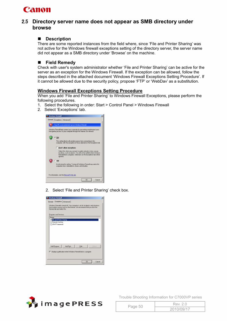
Description There are some reported instances from the field where, since ‘File and Printer Sharing’ was not active for the Windows firewall exceptions setting of the directory server, the server name did not appear as a SMB directory under ‘Browse’ on the machine. Field Remedy Check with user's system administrator whether ‘File and Printer Sharing’ can be active for the server as an exception for the Windows Firewall. If the exception can be allowed, follow the steps described in the attached document ‘Windows Firewall Exceptions Setting Procedure’. If it cannot be allowed due to the security policy, propose ‘FTP’ or ‘WebDav’ as a substitution. Windows Firewall Exceptions Setting Procedure When you add ‘File and Printer Sharing’ to Windows Firewall Exceptions, please perform the following procedures. 1. Select the following in order: Start > Control Panel > Windows Firewall 2. Select ‘Exceptions’ tab.
2. Select ‘File and Printer Sharing’ check box.
Trouble Shooting Information for C7000VP series
Page 51 Rev. 2.0 2010/09/17
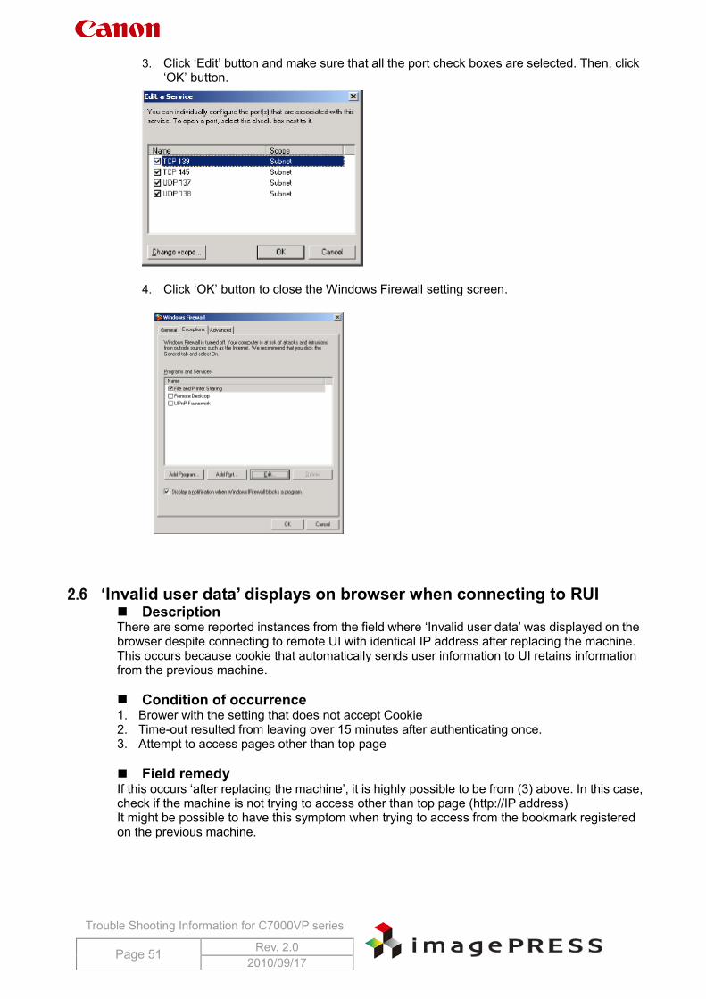
3. Click ‘Edit’ button and make sure that all the port check boxes are selected. Then, click ‘OK’ button.
4. Click ‘OK’ button to close the Windows Firewall setting screen.
2.6 ‘Invalid user data’ displays on browser when connecting to RUI
Description There are some reported instances from the field where ‘Invalid user data’ was displayed on the browser despite connecting to remote UI with identical IP address after replacing the machine. This occurs because cookie that automatically sends user information to UI retains information from the previous machine. Condition of occurrence 1. Brower with the setting that does not accept Cookie 2. Time-out resulted from leaving over 15 minutes after authenticating once. 3. Attempt to access pages other than top page Field remedy If this occurs ‘after replacing the machine’, it is highly possible to be from (3) above. In this case, check if the machine is not trying to access other than top page (http://IP address) It might be possible to have this symptom when trying to access from the bookmark registered on the previous machine.
Trouble Shooting Information for C7000VP series
Page 52 Rev. 2.0 2010/09/17
2.7 When importing paper database via RUI, parameters are not carried over Description When selecting ‘Basic’ under Additional Functions > System Settings > Device Information Delivery Settings > Paper Information settings, all parameters are not carried over.
- All the information: including revised information is carried over - Basic: Only ‘Name’, ‘Basis weight’, ‘Type’, ‘Color’, ‘Creep (Displacement) Correct.’ are carried over.
Field Remedy Select ‘All the information’ under Additional Functions > System Settings > Device Information Delivery Settings > Paper Information settings.
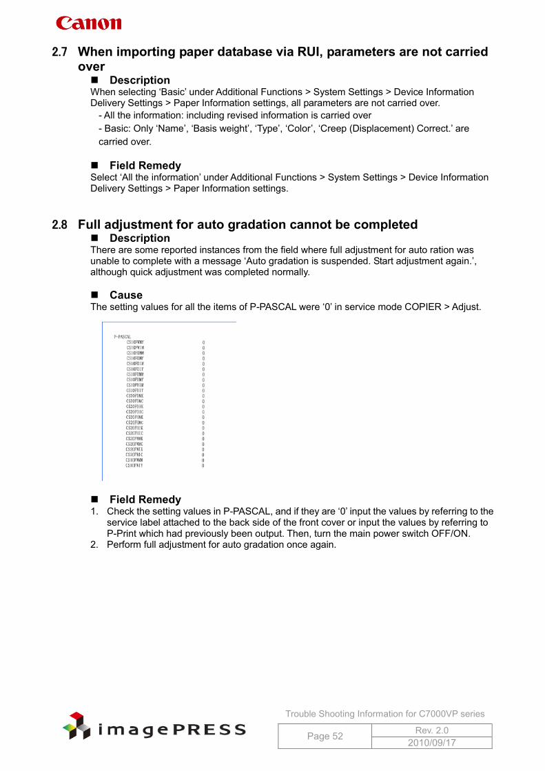
2.8 Full adjustment for auto gradation cannot be completed Description There are some reported instances from the field where full adjustment for auto ration was unable to complete with a message ‘Auto gradation is suspended. Start adjustment again.’, although quick adjustment was completed normally. Cause The setting values for all the items of P-PASCAL were ‘0’ in service mode COPIER > Adjust.
Field Remedy 1. Check the setting values in P-PASCAL, and if they are ‘0’ input the values by referring to the
service label attached to the back side of the front cover or input the values by referring to P-Print which had previously been output. Then, turn the main power switch OFF/ON.
2. Perform full adjustment for auto gradation once again.
Trouble Shooting Information for C7000VP series
Page 53 Rev. 2.0 2010/09/17
2.9 Noise from around developing drive assembly/Cracked developing drive gear
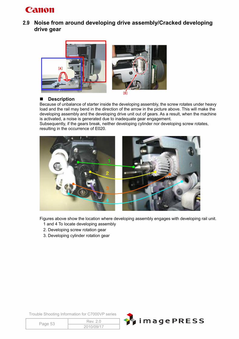
Description Because of unbalance of starter inside the developing assembly, the screw rotates under heavy load and the rail may bend in the direction of the arrow in the picture above. This will make the developing assembly and the developing drive unit out of gears. As a result, when the machine is activated, a noise is generated due to inadequate gear engagement. Subsequently, if the gears break, neither developing cylinder nor developing screw rotates, resulting in the occurrence of E020.
Figures above show the location where developing assembly engages with developing rail unit.
1 and 4 To locate developing assembly 2. Developing screw rotation gear 3. Developing cylinder rotation gear
1
2
3
4
Trouble Shooting Information for C7000VP series
Page 54 Rev. 2.0 2010/09/17
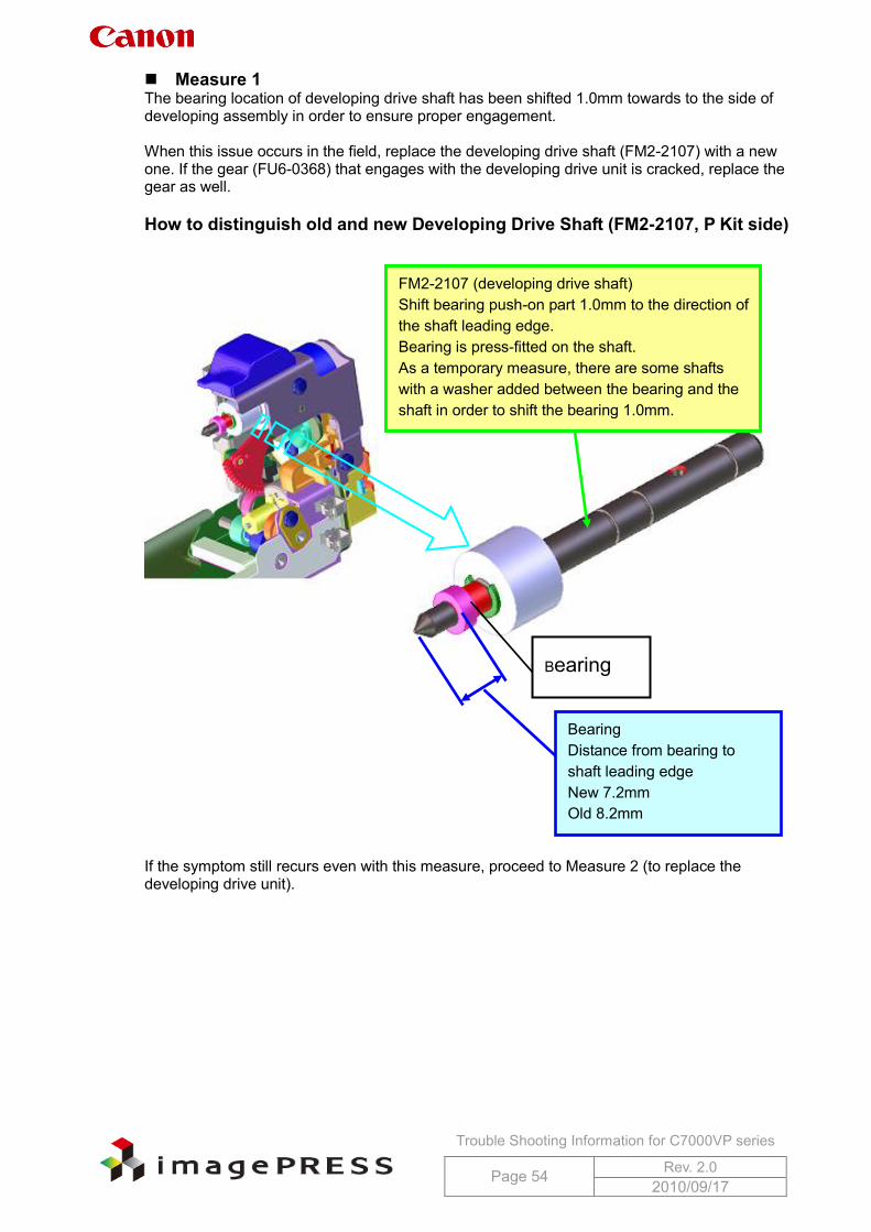
Measure 1 The bearing location of developing drive shaft has been shifted 1.0mm towards to the side of developing assembly in order to ensure proper engagement. When this issue occurs in the field, replace the developing drive shaft (FM2-2107) with a new one. If the gear (FU6-0368) that engages with the developing drive unit is cracked, replace the gear as well. How to distinguish old and new Developing Drive Shaft (FM2-2107, P Kit side)
If the symptom still recurs even with this measure, proceed to Measure 2 (to replace the developing drive unit).
Bearing
Bearing Distance from bearing to shaft leading edge New 7.2mm Old 8.2mm
FM2-2107 (developing drive shaft) Shift bearing push-on part 1.0mm to the direction of the shaft leading edge. Bearing is press-fitted on the shaft. As a temporary measure, there are some shafts with a washer added between the bearing and the shaft in order to shift the bearing 1.0mm.
Trouble Shooting Information for C7000VP series
Page 55 Rev. 2.0 2010/09/17
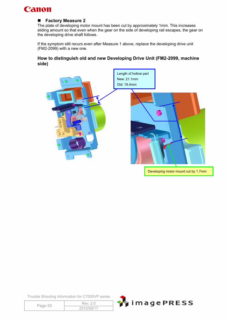
Factory Measure 2 The plate of developing motor mount has been cut by approximately 1mm. This increases sliding amount so that even when the gear on the side of developing rail escapes, the gear on the developing drive shaft follows. If the symptom still recurs even after Measure 1 above, replace the developing drive unit (FM2-2099) with a new one. How to distinguish old and new Developing Drive Unit (FM2-2099, machine side)
Developing motor mount cut by 1.7mm
Length of hollow part New: 21.1mm Old: 19.4mm
Trouble Shooting Information for C7000VP series
Page 56 Rev. 2.0 2010/09/17
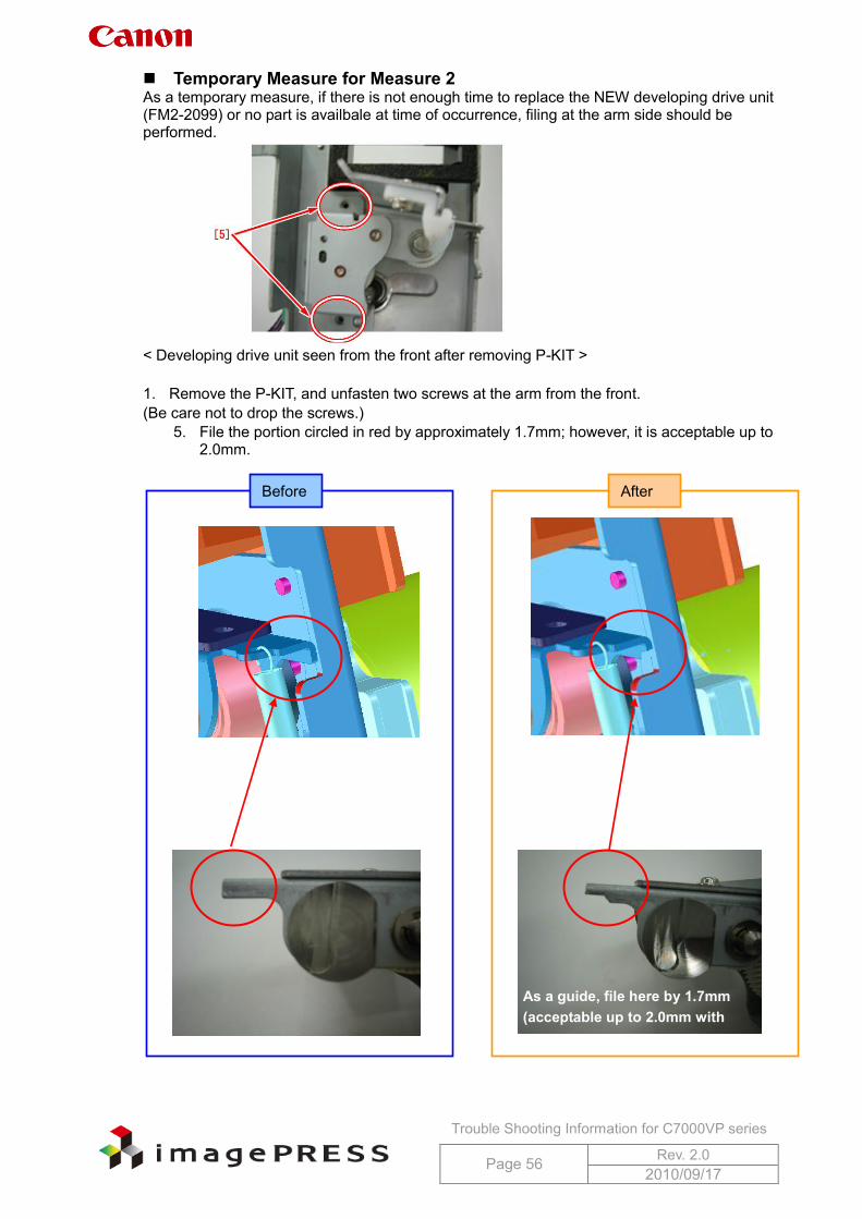
Temporary Measure for Measure 2 As a temporary measure, if there is not enough time to replace the NEW developing drive unit (FM2-2099) or no part is availbale at time of occurrence, filing at the arm side should be performed.
< Developing drive unit seen from the front after removing P-KIT > 1. Remove the P-KIT, and unfasten two screws at the arm from the front. (Be care not to drop the screws.)
5. File the portion circled in red by approximately 1.7mm; however, it is acceptable up to 2.0mm.
As a guide, file here by 1.7mm (acceptable up to 2.0mm with filing)
Before After
Trouble Shooting Information for C7000VP series
Page 57 Rev. 2.0 2010/09/17
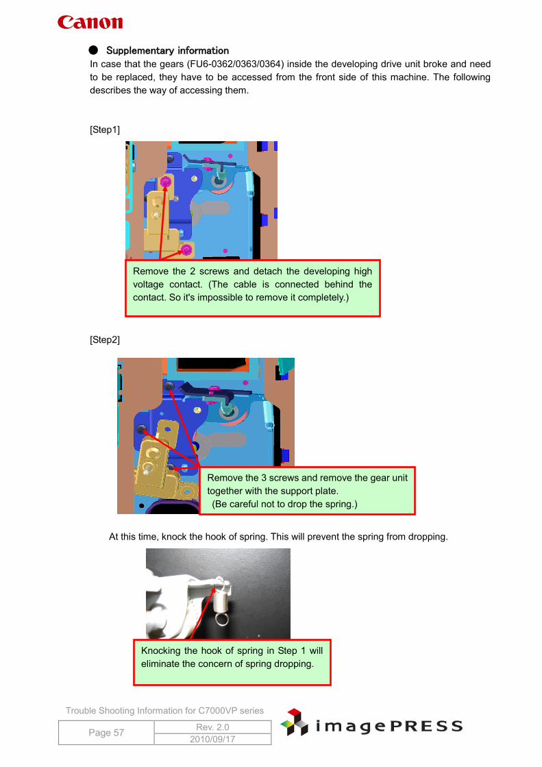
● Supplementary information In case that the gears (FU6-0362/0363/0364) inside the developing drive unit broke and need to be replaced, they have to be accessed from the front side of this machine. The following describes the way of accessing them. [Step1] [Step2]
At this time, knock the hook of spring. This will prevent the spring from dropping.
Remove the 2 screws and detach the developing high voltage contact. (The cable is connected behind the contact. So it's impossible to remove it completely.)
Remove the 3 screws and remove the gear unit together with the support plate. (Be careful not to drop the spring.)
Knocking the hook of spring in Step 1 will eliminate the concern of spring dropping.
Trouble Shooting Information for C7000VP series
Page 58 Rev. 2.0 2010/09/17
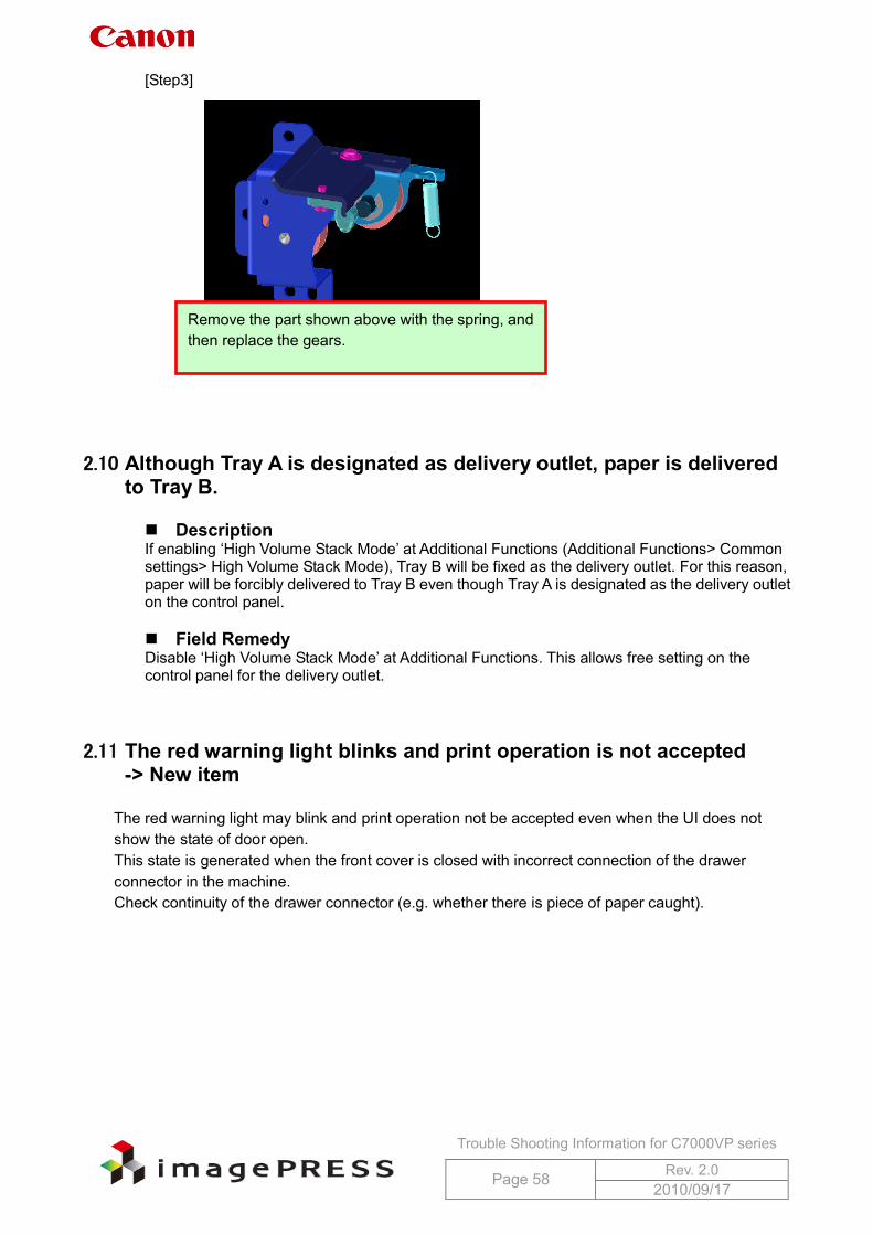
[Step3]
2.10 Although Tray A is designated as delivery outlet, paper is delivered to Tray B.
Description If enabling ‘High Volume Stack Mode’ at Additional Functions (Additional Functions> Common settings> High Volume Stack Mode), Tray B will be fixed as the delivery outlet. For this reason, paper will be forcibly delivered to Tray B even though Tray A is designated as the delivery outlet on the control panel. Field Remedy Disable ‘High Volume Stack Mode’ at Additional Functions. This allows free setting on the control panel for the delivery outlet.
2.11 The red warning light blinks and print operation is not accepted -> New item
The red warning light may blink and print operation not be accepted even when the UI does not
show the state of door open. This state is generated when the front cover is closed with incorrect connection of the drawer connector in the machine. Check continuity of the drawer connector (e.g. whether there is piece of paper caught).
Remove the part shown above with the spring, and then replace the gears.
Trouble Shooting Information for C7000VP series
Page 59 Rev. 2.0 2010/09/17
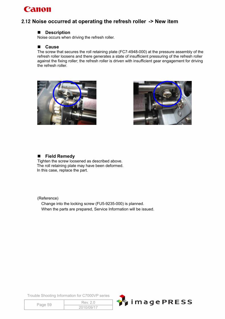
2.12 Noise occurred at operating the refresh roller -> New item Description Noise occurs when driving the refresh roller. Cause The screw that secures the roll retaining plate (FC7-4948-000) at the pressure assembly of the refresh roller loosens and there generates a state of insufficient pressuring of the refresh roller against the fixing roller; the refresh roller is driven with insufficient gear engagement for driving the refresh roller.
Field Remedy Tighten the screw loosened as described above. The roll retaining plate may have been deformed. In this case, replace the part. (Reference)
Change into the locking screw (FU5-9235-000) is planned. When the parts are prepared, Service Information will be issued.
Trouble Shooting Information for C7000VP series
Page 60 Rev. 2.0 2010/09/17
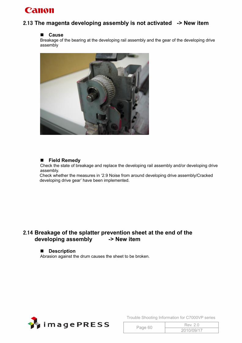
2.13 The magenta developing assembly is not activated -> New item Cause Breakage of the bearing at the developing rail assembly and the gear of the developing drive assembly
Field Remedy Check the state of breakage and replace the developing rail assembly and/or developing drive assembly. Check whether the measures in ‘2.9 Noise from around developing drive assembly/Cracked developing drive gear’ have been implemented.
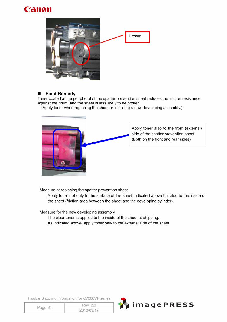
2.14 Breakage of the splatter prevention sheet at the end of the developing assembly -> New item
Description Abrasion against the drum causes the sheet to be broken.
Trouble Shooting Information for C7000VP series
Page 61 Rev. 2.0 2010/09/17
Field Remedy Toner coated at the peripheral of the spatter prevention sheet reduces the friction resistance against the drum, and the sheet is less likely to be broken.
(Apply toner when replacing the sheet or installing a new developing assembly.)
Measure at replacing the spatter prevention sheet Apply toner not only to the surface of the sheet indicated above but also to the inside of the sheet (friction area between the sheet and the developing cylinder).
Measure for the new developing assembly The clear toner is applied to the inside of the sheet at shipping. As indicated above, apply toner only to the external side of the sheet.
Broken
Apply toner also to the front (external) side of the spatter prevention sheet. (Both on the front and rear sides)
Trouble Shooting Information for C7000VP series
Page 62 Rev. 2.0 2010/09/17
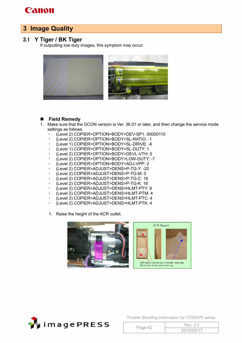
3 Image Quality 3.1 Y Tiger / BK Tiger
If outputting low duty images, this symptom may occur.
Field Remedy 1. Make sure that the DCON version is Ver. 36.01 or later, and then change the service mode
settings as follows. (Level 2) COPIER>OPTION>BODY>DEV-SP1: 00000110 (Level 2) COPIER>OPTION>BODY>SL-RATIO: -1 (Level 1) COPIER>OPTION>BODY>SL-DRIVE: -6 (Level 1) COPIER>OPTION>BODY>SL-DUTY: 1 (Level 2) COPIER>OPTION>BODY>DEVL-VTH: 5 (Level 2) COPIER>OPTION>BODY>LOW-DUTY: -7 (Level 2) COPIER>OPTION>BODY>ADJ-VPP: 2 (Level 2) COPIER>ADJUST>DENS>P-TG-Y: -20 (Level 2) COPIER>ADJUST>DENS>P-TG-M: 0 (Level 2) COPIER>ADJUST>DENS>P-TG-C: 16 (Level 2) COPIER>ADJUST>DENS>P-TG-K: 16 (Level 2) COPIER>ADJUST>DENS>HLMT-PTY: 9 (Level 2) COPIER>ADJUST>DENS>HLMT-PTM: 4 (Level 2) COPIER>ADJUST>DENS>HLMT-PTC: 4 (Level 2) COPIER>ADJUST>DENS>HLMT-PTK: 4
1. Raise the height of the ACR outlet.

Trouble Shooting Information for C7000VP series
Page 63 Rev. 2.0 2010/09/17
Check items at time of occurrence Please collect the following items from the customer site.
P-Print at the time of tiger occurrence Solid image for each color Y/M/C/BK at the time of tiger occurrence
* For the latest information, refer to 3.21 Starter overflow.
Trouble Shooting Information for C7000VP series
Page 64 Rev. 2.0 2010/09/17
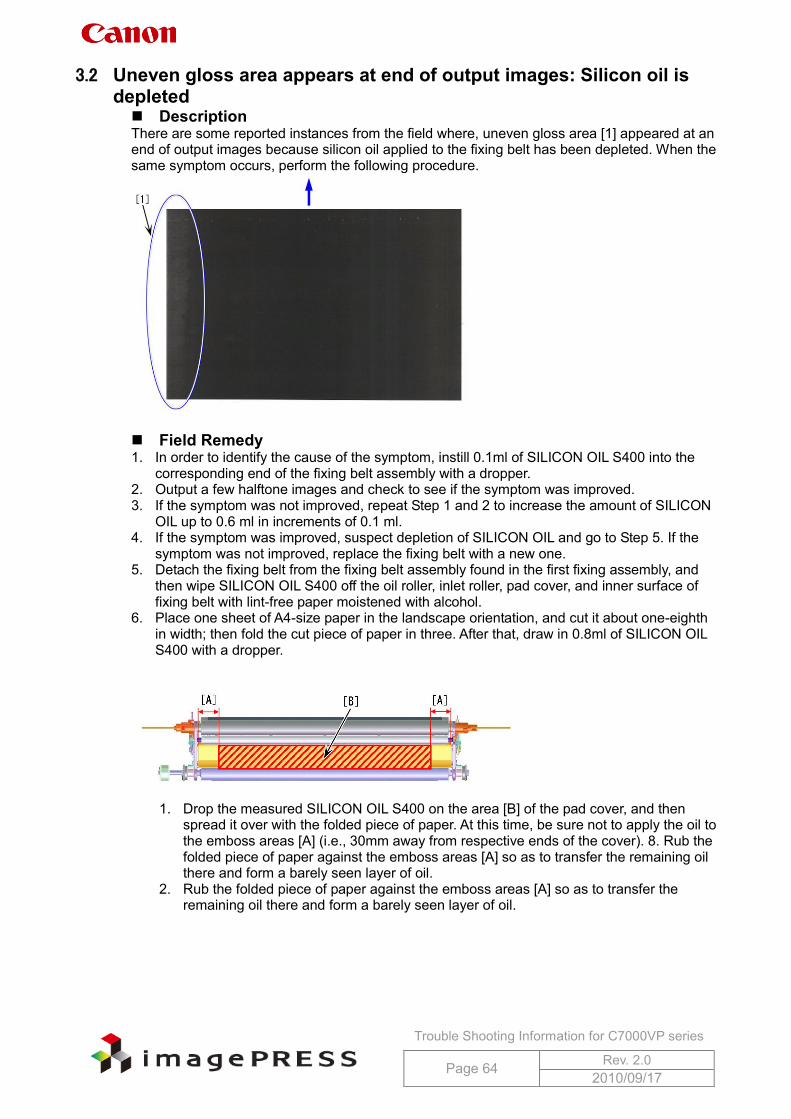
3.2 Uneven gloss area appears at end of output images: Silicon oil is depleted Description There are some reported instances from the field where, uneven gloss area [1] appeared at an end of output images because silicon oil applied to the fixing belt has been depleted. When the same symptom occurs, perform the following procedure.
Field Remedy 1. In order to identify the cause of the symptom, instill 0.1ml of SILICON OIL S400 into the
corresponding end of the fixing belt assembly with a dropper. 2. Output a few halftone images and check to see if the symptom was improved. 3. If the symptom was not improved, repeat Step 1 and 2 to increase the amount of SILICON
OIL up to 0.6 ml in increments of 0.1 ml. 4. If the symptom was improved, suspect depletion of SILICON OIL and go to Step 5. If the
symptom was not improved, replace the fixing belt with a new one. 5. Detach the fixing belt from the fixing belt assembly found in the first fixing assembly, and
then wipe SILICON OIL S400 off the oil roller, inlet roller, pad cover, and inner surface of fixing belt with lint-free paper moistened with alcohol.
6. Place one sheet of A4-size paper in the landscape orientation, and cut it about one-eighth in width; then fold the cut piece of paper in three. After that, draw in 0.8ml of SILICON OIL S400 with a dropper.
1. Drop the measured SILICON OIL S400 on the area [B] of the pad cover, and then
spread it over with the folded piece of paper. At this time, be sure not to apply the oil to the emboss areas [A] (i.e., 30mm away from respective ends of the cover). 8. Rub the folded piece of paper against the emboss areas [A] so as to transfer the remaining oil there and form a barely seen layer of oil.
2. Rub the folded piece of paper against the emboss areas [A] so as to transfer the remaining oil there and form a barely seen layer of oil.
Trouble Shooting Information for C7000VP series
Page 65 Rev. 2.0 2010/09/17
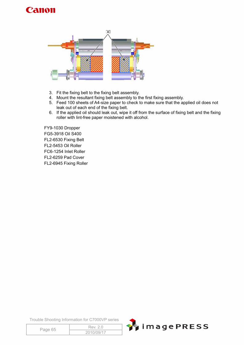
3. Fit the fixing belt to the fixing belt assembly. 4. Mount the resultant fixing belt assembly to the first fixing assembly. 5. Feed 100 sheets of A4-size paper to check to make sure that the applied oil does not
leak out of each end of the fixing belt. 6. If the applied oil should leak out, wipe it off from the surface of fixing belt and the fixing
roller with lint-free paper moistened with alcohol.
FY9-1030 DropperFG5-3918 Oil S400FL2-6530 Fixing Belt FL2-5453 Oil Roller FC6-1254 Inlet Roller FL2-6259 Pad Cover FL2-6945 Fixing Roller
Trouble Shooting Information for C7000VP series
Page 66 Rev. 2.0 2010/09/17
3.3 Soiled back side due to toner at secondary transfer external roller Description The following two controls have been added in order to improve toner-cleaning performance for the secondary transfer external roller. 1. Shorten the amount of time to bias the secondary transfer external roller. 2. In order to clean the roller, add a cleaning sequence in which a black band patch is formed
during post rotation and toner is applied to the secondary transfer external roller on the condition that the following two requirements are met. Each counters for the secondary transfer external roller and the secondary transfer
cleaning brush roller is 5000 prints or less (in case of LTR paper) One job is 50 prints or less (in case of LTR paper)
Field Remedy 1. Upgrade DCON to Ver26.05, and set service mode (level 2) > COPIER > ADJUST > HV-TR
> 2ELSW > 1. (2ELSW is to switch the secondary transfer static eliminator bias to ON or OFF, 0: OFF, 1: ON)
2. Replace the secondary transfer external roller and the secondary transfer cleaning brush roller (2 pcs.) at the same time. Otherwise, a difference in abrasion between these two rollers may worsen this symptom.
3. Clear these rollers’ counter to 0 after replacement in the service mode below. COPIER > Counter > DRBL-1 > 2TR-R0LL (secondary transfer external roller) COPIER > Counter > DRBL-1 > 2TRCL-RL (secondary transfer cleaning brush roller)
* The newly added sequence will operate in sync with the counter 2TRCL-RL.
3.4 Soiled back side cases reported from field Case #1: Due to broken shaft of toner discharging screw There are some reported instances from the field where this symptom was caused by a broken shaft of the toner discharging screw of the secondary transfer external roller-cleaning unit. Thus, check the screw shaft at the occurrence of soiled backside. Note that it is difficult to confirm the breakage visually. Case #2: Due to dirty fixing feed belt Clean the fixing feed belt. Case #3: Due to dirty fixing inlet guide assembly Clean the fixing inlet guide. Case #4: Due to waste toner accumulated in secondary transfer cleaning
unit Break down toner accumulation inside the unit.
Trouble Shooting Information for C7000VP series
Page 67 Rev. 2.0 2010/09/17
3.5 Magenta fogging throughout page /E020-02b1 during continuous printing job
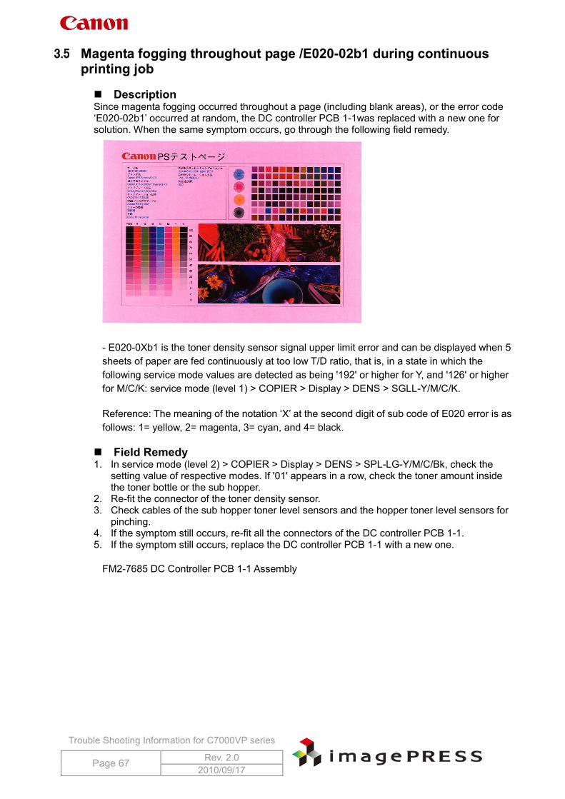
Description Since magenta fogging occurred throughout a page (including blank areas), or the error code ‘E020-02b1’ occurred at random, the DC controller PCB 1-1was replaced with a new one for solution. When the same symptom occurs, go through the following field remedy.
- E020-0Xb1 is the toner density sensor signal upper limit error and can be displayed when 5 sheets of paper are fed continuously at too low T/D ratio, that is, in a state in which the following service mode values are detected as being '192' or higher for Y, and '126' or higher for M/C/K: service mode (level 1) > COPIER > Display > DENS > SGLL-Y/M/C/K.
Reference: The meaning of the notation ‘X’ at the second digit of sub code of E020 error is as follows: 1= yellow, 2= magenta, 3= cyan, and 4= black.
Field Remedy 1. In service mode (level 2) > COPIER > Display > DENS > SPL-LG-Y/M/C/Bk, check the
setting value of respective modes. If '01' appears in a row, check the toner amount inside the toner bottle or the sub hopper.
2. Re-fit the connector of the toner density sensor. 3. Check cables of the sub hopper toner level sensors and the hopper toner level sensors for
pinching. 4. If the symptom still occurs, re-fit all the connectors of the DC controller PCB 1-1. 5. If the symptom still occurs, replace the DC controller PCB 1-1 with a new one.
FM2-7685 DC Controller PCB 1-1 Assembly
Trouble Shooting Information for C7000VP series
Page 68 Rev. 2.0 2010/09/17
3.6 Color displacement in main scanning direction Description There are some reported instances from the field where cyan color displacement occurred in the main scanning direction. When the same symptom occurs, go through the field remedy below. Cause Since J1131 connectors, which extend from respective DC controller PCBs (1 through 3) to the laser unit, had poor contact, the cyan laser beam was not output properly. Field Remedy 1. Refit all J1131 connectors on the DC controller PCB 1-3. 2. Refit J3553C on the laser driver sub PCB ‘UN173.’ Reference: For other colors, refer to the matrix below.
Color DC controller PCB Laser driver sub PCB Yellow J1111 J3553y Magenta J1121 J3553M Black J1141 J3553Bk
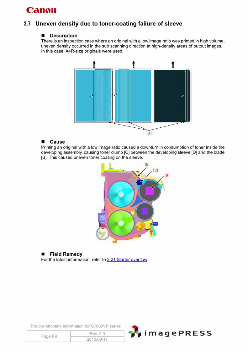
Trouble Shooting Information for C7000VP series
Page 69 Rev. 2.0 2010/09/17
3.7 Uneven density due to toner-coating failure of sleeve Description There is an inspection case where an original with a low image ratio was printed in high volume, uneven density occurred in the sub scanning direction at high-density areas of output images. In this case, A4R-size originals were used.
Cause Printing an original with a low image ratio caused a downturn in consumption of toner inside the developing assembly, causing toner clump [C] between the developing sleeve [D] and the blade [B]. This caused uneven toner coating on the sleeve.
Field Remedy For the latest information, refer to 3.21 Starter overflow.
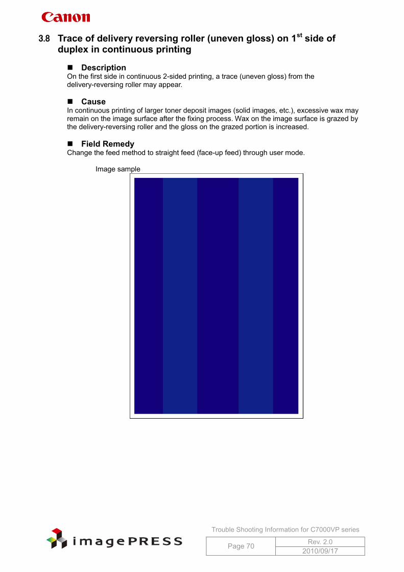
Trouble Shooting Information for C7000VP series
Page 70 Rev. 2.0 2010/09/17
3.8 Trace of delivery reversing roller (uneven gloss) on 1st side of duplex in continuous printing
Description On the first side in continuous 2-sided printing, a trace (uneven gloss) from the delivery-reversing roller may appear. Cause In continuous printing of larger toner deposit images (solid images, etc.), excessive wax may remain on the image surface after the fixing process. Wax on the image surface is grazed by the delivery-reversing roller and the gloss on the grazed portion is increased. Field Remedy Change the feed method to straight feed (face-up feed) through user mode.
Image sample
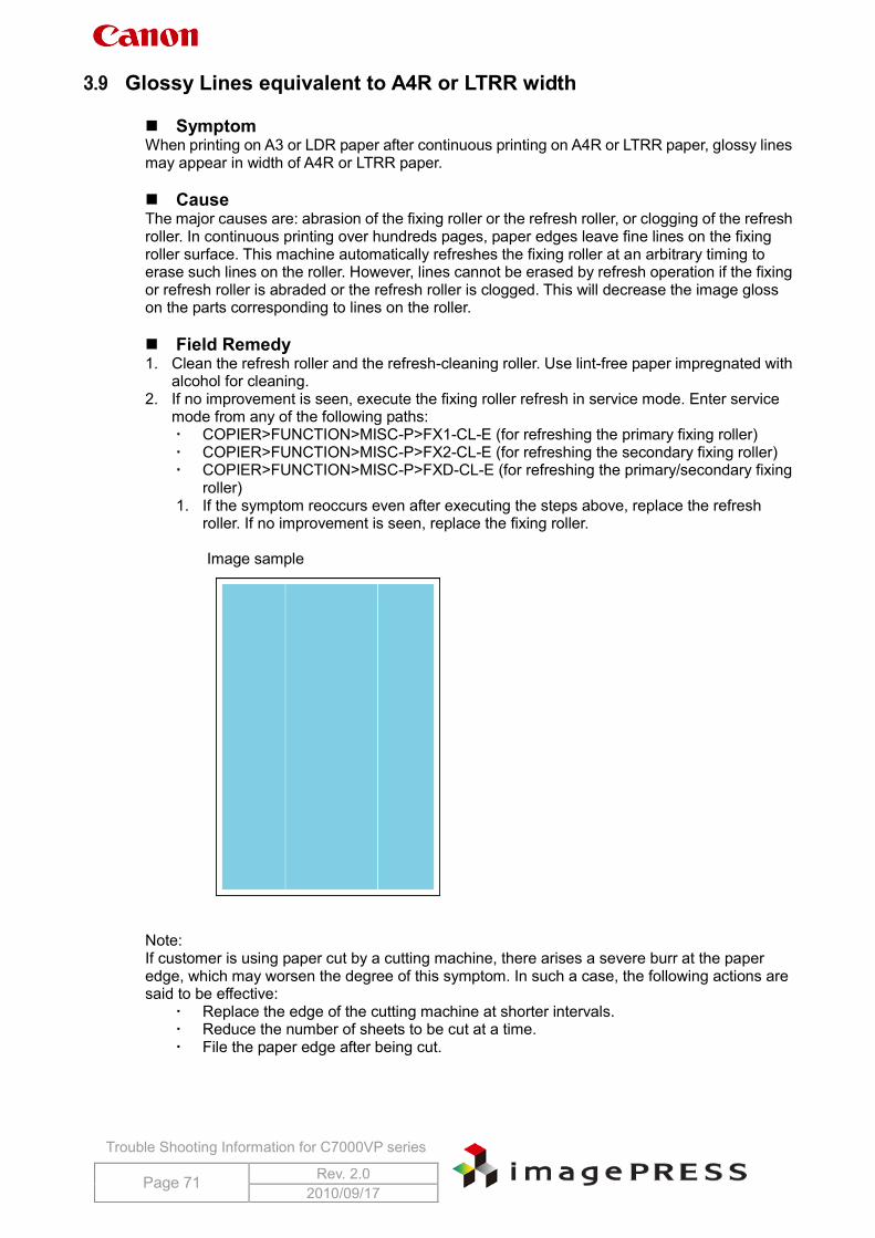
Trouble Shooting Information for C7000VP series
Page 71 Rev. 2.0 2010/09/17
3.9 Glossy Lines equivalent to A4R or LTRR width
Symptom When printing on A3 or LDR paper after continuous printing on A4R or LTRR paper, glossy lines may appear in width of A4R or LTRR paper. Cause The major causes are: abrasion of the fixing roller or the refresh roller, or clogging of the refresh roller. In continuous printing over hundreds pages, paper edges leave fine lines on the fixing roller surface. This machine automatically refreshes the fixing roller at an arbitrary timing to erase such lines on the roller. However, lines cannot be erased by refresh operation if the fixing or refresh roller is abraded or the refresh roller is clogged. This will decrease the image gloss on the parts corresponding to lines on the roller. Field Remedy 1. Clean the refresh roller and the refresh-cleaning roller. Use lint-free paper impregnated with
alcohol for cleaning. 2. If no improvement is seen, execute the fixing roller refresh in service mode. Enter service
mode from any of the following paths: COPIER>FUNCTION>MISC-P>FX1-CL-E (for refreshing the primary fixing roller) COPIER>FUNCTION>MISC-P>FX2-CL-E (for refreshing the secondary fixing roller) COPIER>FUNCTION>MISC-P>FXD-CL-E (for refreshing the primary/secondary fixing
roller) 1. If the symptom reoccurs even after executing the steps above, replace the refresh
roller. If no improvement is seen, replace the fixing roller.
Image sample
Note: If customer is using paper cut by a cutting machine, there arises a severe burr at the paper edge, which may worsen the degree of this symptom. In such a case, the following actions are said to be effective:
Replace the edge of the cutting machine at shorter intervals. Reduce the number of sheets to be cut at a time. File the paper edge after being cut.
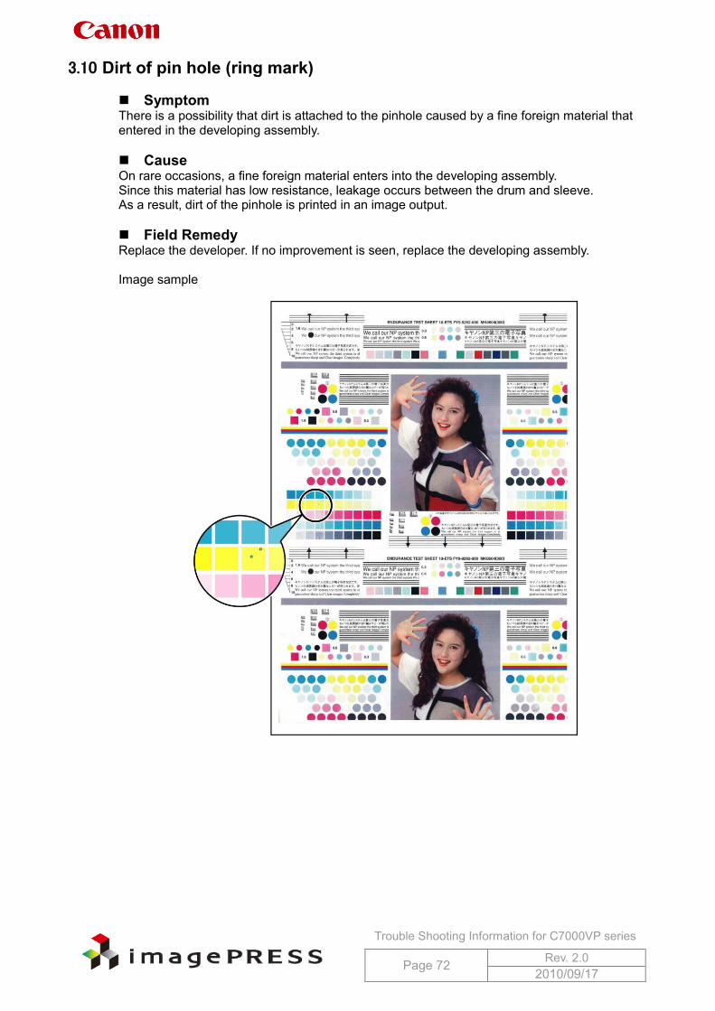
Trouble Shooting Information for C7000VP series
Page 72 Rev. 2.0 2010/09/17
3.10 Dirt of pin hole (ring mark) Symptom There is a possibility that dirt is attached to the pinhole caused by a fine foreign material that entered in the developing assembly. Cause On rare occasions, a fine foreign material enters into the developing assembly. Since this material has low resistance, leakage occurs between the drum and sleeve. As a result, dirt of the pinhole is printed in an image output. Field Remedy Replace the developer. If no improvement is seen, replace the developing assembly. Image sample
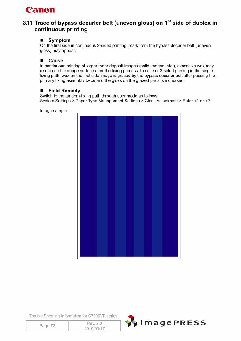
Trouble Shooting Information for C7000VP series
Page 73 Rev. 2.0 2010/09/17
3.11 Trace of bypass decurler belt (uneven gloss) on 1st side of duplex in continuous printing
Symptom On the first side in continuous 2-sided printing, mark from the bypass decurler belt (uneven gloss) may appear. Cause In continuous printing of larger toner deposit images (solid images, etc.), excessive wax may remain on the image surface after the fixing process. In case of 2-sided printing in the single fixing path, wax on the first side image is grazed by the bypass decurler belt after passing the primary fixing assembly twice and the gloss on the grazed parts is increased. Field Remedy Switch to the tandem-fixing path through user mode as follows. System Settings > Paper Type Management Settings > Gloss Adjustment > Enter +1 or +2 Image sample
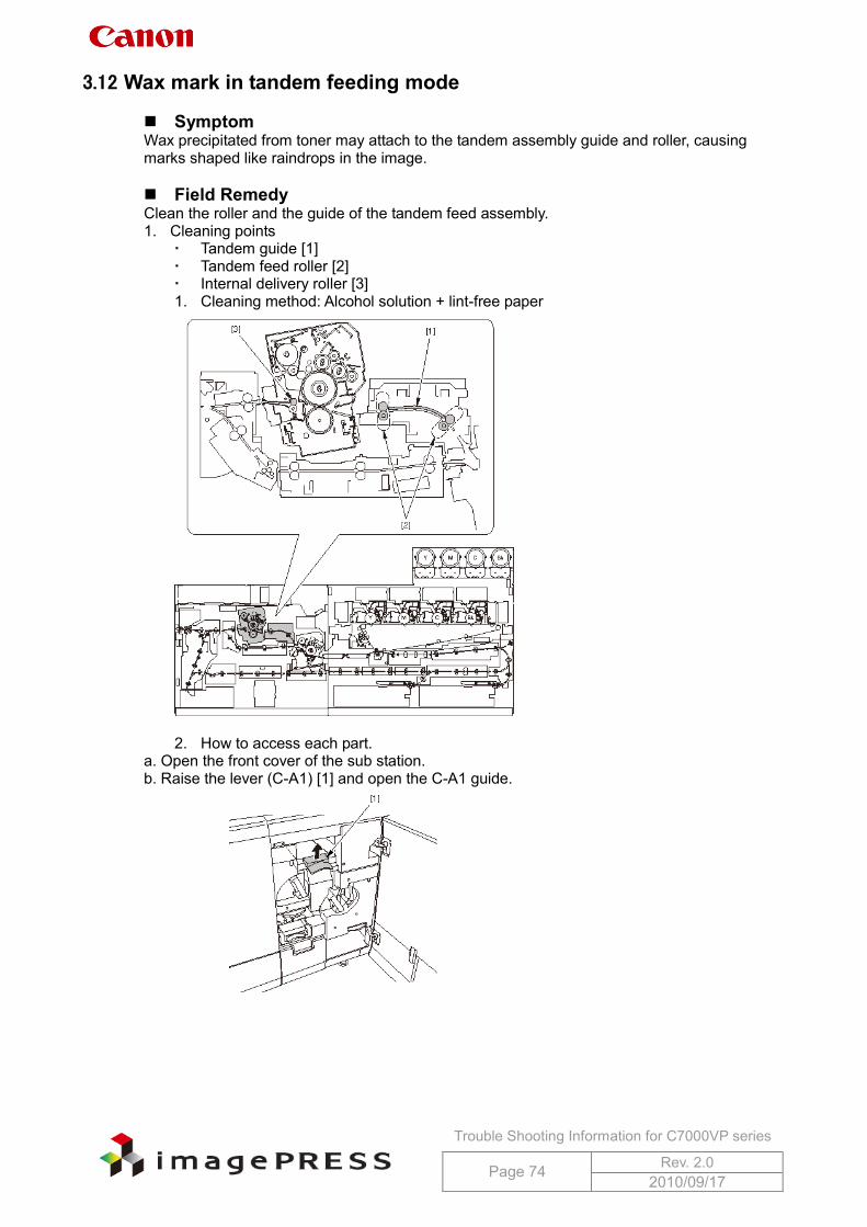
Trouble Shooting Information for C7000VP series
Page 74 Rev. 2.0 2010/09/17
3.12 Wax mark in tandem feeding mode Symptom Wax precipitated from toner may attach to the tandem assembly guide and roller, causing marks shaped like raindrops in the image. Field Remedy Clean the roller and the guide of the tandem feed assembly. 1. Cleaning points
Tandem guide [1] Tandem feed roller [2] Internal delivery roller [3] 1. Cleaning method: Alcohol solution + lint-free paper
2. How to access each part.
a. Open the front cover of the sub station. b. Raise the lever (C-A1) [1] and open the C-A1 guide.
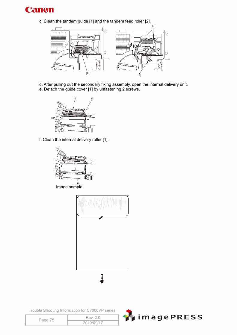
Trouble Shooting Information for C7000VP series
Page 75 Rev. 2.0 2010/09/17
c. Clean the tandem guide [1] and the tandem feed roller [2].
d. After pulling out the secondary fixing assembly, open the internal delivery unit. e. Detach the guide cover [1] by unfastening 2 screws.
f. Clean the internal delivery roller [1].
Image sample
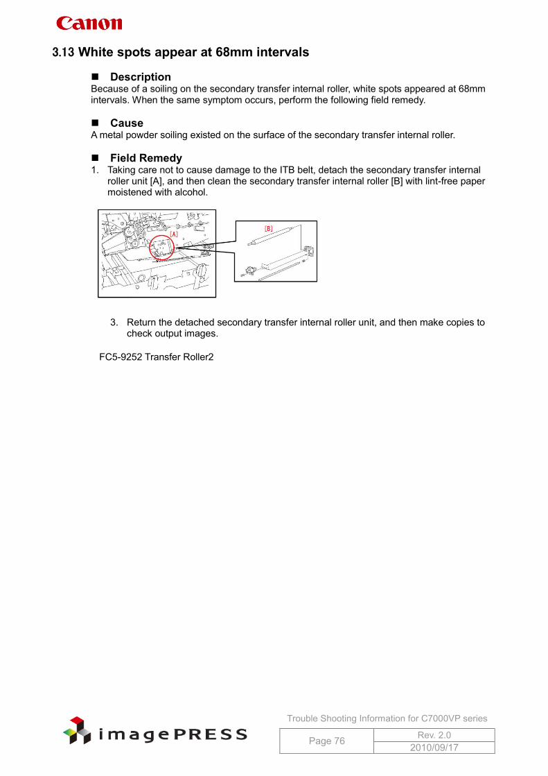
Trouble Shooting Information for C7000VP series
Page 76 Rev. 2.0 2010/09/17
3.13 White spots appear at 68mm intervals Description Because of a soiling on the secondary transfer internal roller, white spots appeared at 68mm intervals. When the same symptom occurs, perform the following field remedy. Cause A metal powder soiling existed on the surface of the secondary transfer internal roller. Field Remedy 1. Taking care not to cause damage to the ITB belt, detach the secondary transfer internal
roller unit [A], and then clean the secondary transfer internal roller [B] with lint-free paper moistened with alcohol.
3. Return the detached secondary transfer internal roller unit, and then make copies to
check output images.
FC5-9252 Transfer Roller2
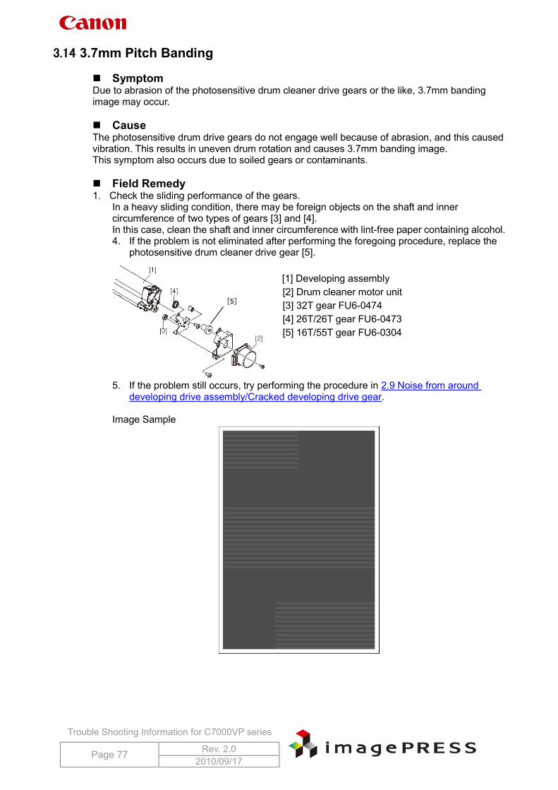
Trouble Shooting Information for C7000VP series
Page 77 Rev. 2.0 2010/09/17
[5]
3.14 3.7mm Pitch Banding Symptom Due to abrasion of the photosensitive drum cleaner drive gears or the like, 3.7mm banding image may occur. Cause The photosensitive drum drive gears do not engage well because of abrasion, and this caused vibration. This results in uneven drum rotation and causes 3.7mm banding image. This symptom also occurs due to soiled gears or contaminants. Field Remedy 1. Check the sliding performance of the gears.
In a heavy sliding condition, there may be foreign objects on the shaft and inner circumference of two types of gears [3] and [4]. In this case, clean the shaft and inner circumference with lint-free paper containing alcohol. 4. If the problem is not eliminated after performing the foregoing procedure, replace the
photosensitive drum cleaner drive gear [5].
[1] Developing assembly [2] Drum cleaner motor unit [3] 32T gear FU6-0474 [4] 26T/26T gear FU6-0473 [5] 16T/55T gear FU6-0304
5. If the problem still occurs, try performing the procedure in 2.9 Noise from around
developing drive assembly/Cracked developing drive gear.
Image Sample
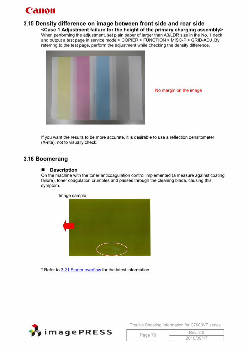
Trouble Shooting Information for C7000VP series
Page 78 Rev. 2.0 2010/09/17
3.15 Density difference on image between front side and rear side <Case 1 Adjustment failure for the height of the primary charging assembly> When performing the adjustment, set plain paper of larger than A3/LDR size in the No. 1 deck and output a test page in service mode > COPIER > FUNCTION > MISC-P > GRID-ADJ .By referring to the test page, perform the adjustment while checking the density difference.
If you want the results to be more accurate, it is desirable to use a reflection densitometer (X-rite), not to visually check.
3.16 Boomerang Description On the machine with the toner anticoagulation control implemented (a measure against coating failure), toner coagulation crumbles and passes through the cleaning blade, causing this symptom.
Image sample
* Refer to 3.21 Starter overflow for the latest information.
No margin on the image
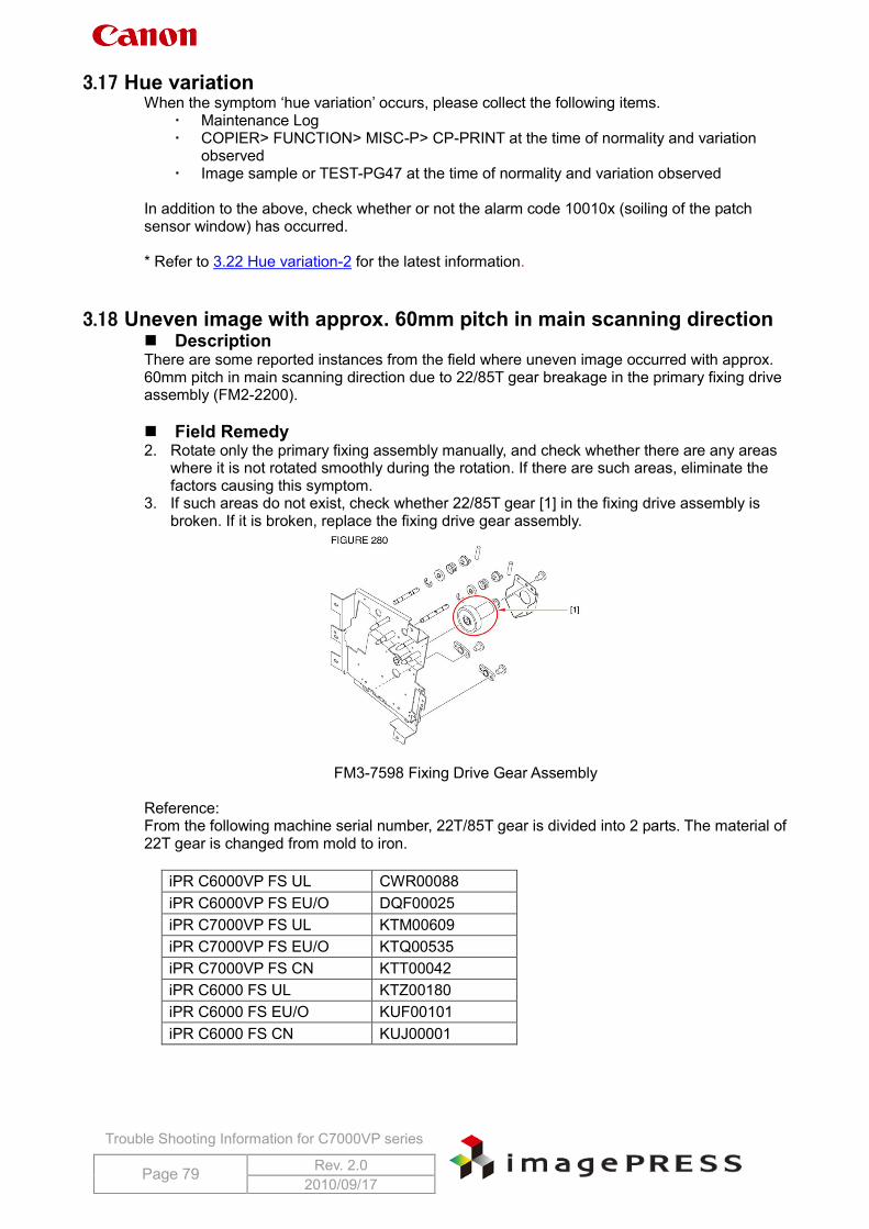
Trouble Shooting Information for C7000VP series
Page 79 Rev. 2.0 2010/09/17
3.17 Hue variation When the symptom ‘hue variation’ occurs, please collect the following items.
Maintenance Log COPIER> FUNCTION> MISC-P> CP-PRINT at the time of normality and variation
observed Image sample or TEST-PG47 at the time of normality and variation observed
In addition to the above, check whether or not the alarm code 10010x (soiling of the patch sensor window) has occurred. * Refer to 3.22 Hue variation-2 for the latest information.
3.18 Uneven image with approx. 60mm pitch in main scanning direction Description There are some reported instances from the field where uneven image occurred with approx. 60mm pitch in main scanning direction due to 22/85T gear breakage in the primary fixing drive assembly (FM2-2200). Field Remedy 2. Rotate only the primary fixing assembly manually, and check whether there are any areas
where it is not rotated smoothly during the rotation. If there are such areas, eliminate the factors causing this symptom.
3. If such areas do not exist, check whether 22/85T gear [1] in the fixing drive assembly is broken. If it is broken, replace the fixing drive gear assembly.
FM3-7598 Fixing Drive Gear Assembly
Reference: From the following machine serial number, 22T/85T gear is divided into 2 parts. The material of 22T gear is changed from mold to iron.
iPR C6000VP FS UL CWR00088 iPR C6000VP FS EU/O DQF00025 iPR C7000VP FS UL KTM00609 iPR C7000VP FS EU/O KTQ00535 iPR C7000VP FS CN KTT00042 iPR C6000 FS UL KTZ00180 iPR C6000 FS EU/O KUF00101 iPR C6000 FS CN KUJ00001
Trouble Shooting Information for C7000VP series
Page 80 Rev. 2.0 2010/09/17
3.19 Sleeve ghost (shadow image) Description There are some reported instances from the field where shadow image (sleeve ghost) appeared at approximately 60mm from the lead edge of paper. Replacement of the developing assembly and starter solved the symptom. * Sleeve ghost is a symptom showing higher density at approximately 60mm from the lead edge of paper in the main scanning direction when outputting halftone images. In order to check if the symptom you are facing is sleeve ghost at the time of occurrence, perform the service mode below to change the peripheral speed ratio of the development cylinder.
COPIER> OPTION> BODY> SL-RATIO When changing the setting to + side, the peripheral speed of the development cylinder accelerates and the area with high density will become narrower. Conversely, when changing to – (minus) side, the area will become wider. In the event that the symptom is identified as sleeve ghost, make the service mode setting change below. Field Remedy 1. Check toner density in the developing assembly and ATR patch value.
Toner density in the developing assembly: Service mode (Level 1) COPIER> DISPLAY> DENS> DENS-Y/M/C/K
ATR patch value: Service mode (Level 2) COPIER> DISPLAY> DENS> DENS-S-Y/M/C/K
2. Depending on the value of DENS-Y/M/C/K. change the setting below. If toner density in the developing assembly displays +1% or higher, change the setting
in service mode (Level2) > COPIER> ADJUST> DENS> HLMT-PTY/M/C/K. If it shows ‘4’ at this point, change it to ‘9’. If it shows ‘9’ at this point, change it to ‘10’.
If toner density in the developing assembly displays lower than +1%, change the setting in service mode (Level2) > COPIER> ADJUST> DENS> P-TG-Y/M/C/K. Input a value adding ‘10’ to current value.
3. Conduct the following operations
Clean around the developing assembly and wipe the surface of ATR patch sensor with alcohol.
Additional Functions> wire cleaning Perform 100 prints for PG10 A3 Additional Functions> wire cleaning Auto gradation adjustment
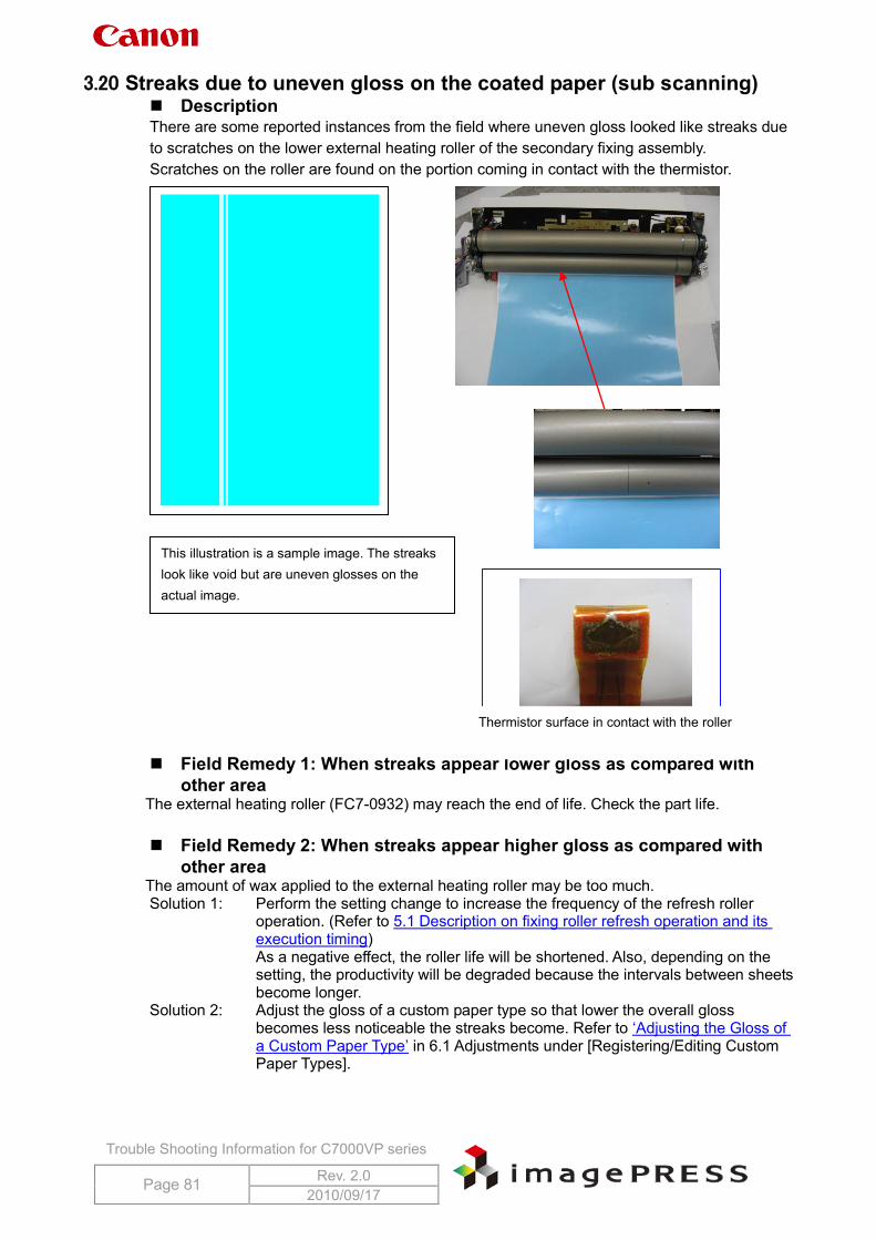
Trouble Shooting Information for C7000VP series
Page 81 Rev. 2.0 2010/09/17
3.20 Streaks due to uneven gloss on the coated paper (sub scanning) Description There are some reported instances from the field where uneven gloss looked like streaks due to scratches on the lower external heating roller of the secondary fixing assembly. Scratches on the roller are found on the portion coming in contact with the thermistor.
Field Remedy 1: When streaks appear lower gloss as compared with
other area The external heating roller (FC7-0932) may reach the end of life. Check the part life. Field Remedy 2: When streaks appear higher gloss as compared with
other area The amount of wax applied to the external heating roller may be too much. Solution 1: Perform the setting change to increase the frequency of the refresh roller
operation. (Refer to 5.1 Description on fixing roller refresh operation and its execution timing)
As a negative effect, the roller life will be shortened. Also, depending on the setting, the productivity will be degraded because the intervals between sheets become longer.
Solution 2: Adjust the gloss of a custom paper type so that lower the overall gloss becomes less noticeable the streaks become. Refer to ‘Adjusting the Gloss of a Custom Paper Type’ in 6.1 Adjustments under [Registering/Editing Custom Paper Types].
This illustration is a sample image. The streaks look like void but are uneven glosses on the actual image.
Thermistor surface in contact with the roller
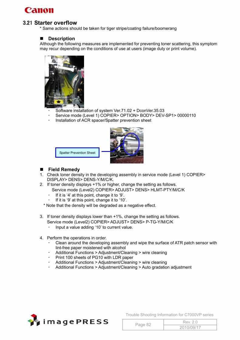
Trouble Shooting Information for C7000VP series
Page 82 Rev. 2.0 2010/09/17
3.21 Starter overflow * Same actions should be taken for tiger stripe/coating failure/boomerang Description Although the following measures are implemented for preventing toner scattering, this symptom may recur depending on the conditions of use at users (image duty or print volume).
Software installation of system Ver.71.02 + DconVer.35.03 Service mode (Level 1) COPIER> OPTION> BODY> DEV-SP1> 00000110 Installation of ACR spacer/Spatter prevention sheet
Field Remedy 1. Check toner density in the developing assembly in service mode (Level 1) COPIER>
DISPLAY> DENS> DENS-Y/M/C/K. 2. If toner density displays +1% or higher, change the setting as follows.
Service mode (Level2) COPIER> ADJUST> DENS> HLMT-PTY/M/C/K If it is ‘4’ at this point, change it to ‘9’. If it is ‘9’ at this point, change it to ‘10’.
* Note that the density will be degraded as a negative effect.
3. If toner density displays lower than +1%, change the setting as follows. Service mode (Level2) COPIER> ADJUST> DENS> P-TG-Y/M/C/K Input a value adding ‘10’ to current value.
4. Perform the operations in order.
Clean around the developing assembly and wipe the surface of ATR patch sensor with lint-free paper moistened with alcohol
Additional Functions > Adjustment/Cleaning > wire cleaning Print 100 sheets of PG10 with LDR paper Additional Functions > Adjustment/Cleaning > wire cleaning Additional Functions > Adjustment/Cleaning > Auto gradation adjustment
Spatter Prevention Sheet
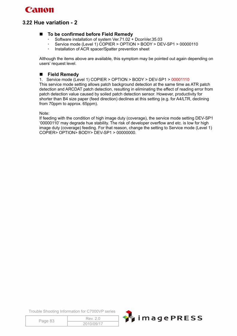
Trouble Shooting Information for C7000VP series
Page 83 Rev. 2.0 2010/09/17
3.22 Hue variation - 2 To be confirmed before Field Remedy
Software installation of system Ver.71.02 + DconVer.35.03 Service mode (Level 1) COPIER > OPTION > BODY > DEV-SP1 > 00000110 Installation of ACR spacer/Spatter prevention sheet
Although the items above are available, this symptom may be pointed out again depending on users’ request level. Field Remedy 1. Service mode (Level 1) COPIER > OPTION > BODY > DEV-SP1 > 00001110 This service mode setting allows patch background detection at the same time as ATR patch detection and ARCDAT patch detection, resulting in eliminating the effect of reading error from patch detection value caused by soiled patch detection sensor. However, productivity for shorter than B4 size paper (feed direction) declines at this setting (e.g. for A4/LTR, declining from 70ppm to approx. 65ppm). Note: If feeding with the condition of high image duty (coverage), the service mode setting DEV-SP1 ‘00000110’ may degrade hue stability. The risk of developer overflow and etc. is low for high image duty (coverage) feeding. For that reason, change the setting to Service mode (Level 1) COPIER> OPTION> BODY> DEV-SP1 > 00000000.
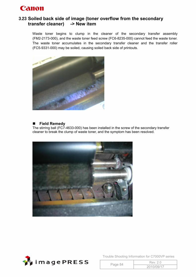
Trouble Shooting Information for C7000VP series
Page 84 Rev. 2.0 2010/09/17
3.23 Soiled back side of image (toner overflow from the secondary transfer cleaner) -> New item
Waste toner begins to clump in the cleaner of the secondary transfer assembly
(FM2-2173-000), and the waste toner feed screw (FC6-8235-000) cannot feed the waste toner. The waste toner accumulates in the secondary transfer cleaner and the transfer roller (FC5-9331-000) may be soiled, causing soiled back side of printouts.
Field Remedy The stirring ball (FC7-4633-000) has been installed in the screw of the secondary transfer cleaner to break the clump of waste toner, and the symptom has been resolved.
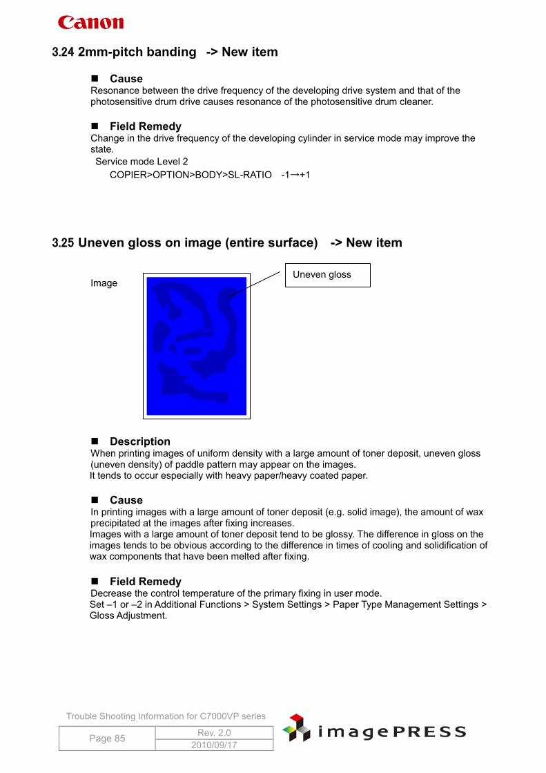
Trouble Shooting Information for C7000VP series
Page 85 Rev. 2.0 2010/09/17
3.24 2mm-pitch banding -> New item Cause Resonance between the drive frequency of the developing drive system and that of the photosensitive drum drive causes resonance of the photosensitive drum cleaner. Field Remedy Change in the drive frequency of the developing cylinder in service mode may improve the state. Service mode Level 2
COPIER>OPTION>BODY>SL-RATIO -1→+1
3.25 Uneven gloss on image (entire surface) -> New item Image Description When printing images of uniform density with a large amount of toner deposit, uneven gloss (uneven density) of paddle pattern may appear on the images. It tends to occur especially with heavy paper/heavy coated paper.
Cause In printing images with a large amount of toner deposit (e.g. solid image), the amount of wax precipitated at the images after fixing increases. Images with a large amount of toner deposit tend to be glossy. The difference in gloss on the images tends to be obvious according to the difference in times of cooling and solidification of wax components that have been melted after fixing. Field Remedy Decrease the control temperature of the primary fixing in user mode. Set –1 or –2 in Additional Functions > System Settings > Paper Type Management Settings > Gloss Adjustment.
Uneven gloss
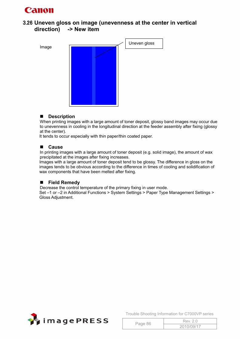
Trouble Shooting Information for C7000VP series
Page 86 Rev. 2.0 2010/09/17
3.26 Uneven gloss on image (unevenness at the center in vertical direction) -> New item
Image Description When printing images with a large amount of toner deposit, glossy band images may occur due to unevenness in cooling in the longitudinal direction at the feeder assembly after fixing (glossy at the center). It tends to occur especially with thin paper/thin coated paper.
Cause In printing images with a large amount of toner deposit (e.g. solid image), the amount of wax precipitated at the images after fixing increases. Images with a large amount of toner deposit tend to be glossy. The difference in gloss on the images tends to be obvious according to the difference in times of cooling and solidification of wax components that have been melted after fixing.
Field Remedy Decrease the control temperature of the primary fixing in user mode. Set –1 or –2 in Additional Functions > System Settings > Paper Type Management Settings > Gloss Adjustment.
Uneven gloss
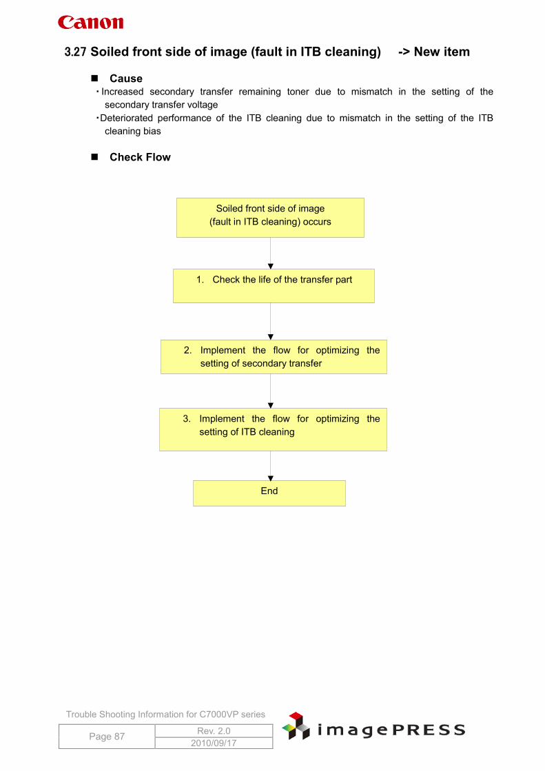
Trouble Shooting Information for C7000VP series
Page 87 Rev. 2.0 2010/09/17
3.27 Soiled front side of image (fault in ITB cleaning) -> New item
Cause ・ Increased secondary transfer remaining toner due to mismatch in the setting of the
secondary transfer voltage ・Deteriorated performance of the ITB cleaning due to mismatch in the setting of the ITB
cleaning bias Check Flow
Soiled front side of image (fault in ITB cleaning) occurs
1. Check the life of the transfer part
2. Implement the flow for optimizing the setting of secondary transfer
3.
3. Implement the flow for optimizing the setting of ITB cleaning
End
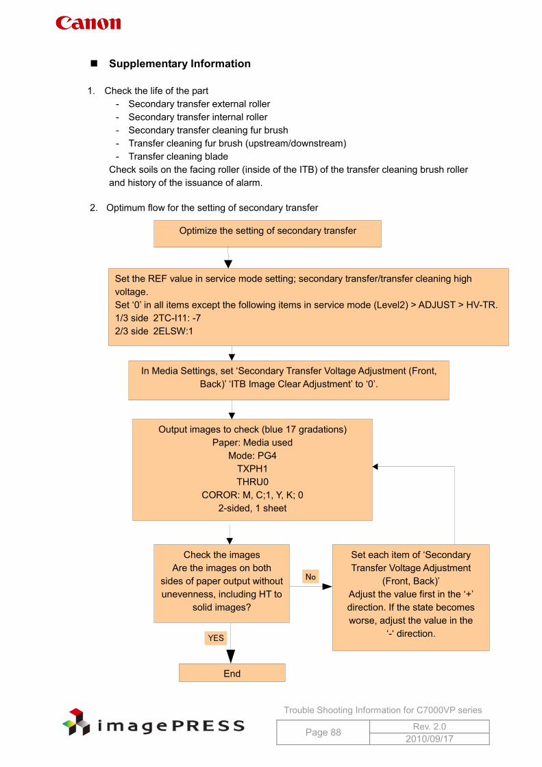
Trouble Shooting Information for C7000VP series
Page 88 Rev. 2.0 2010/09/17
Supplementary Information 1. Check the life of the part
- Secondary transfer external roller - Secondary transfer internal roller - Secondary transfer cleaning fur brush - Transfer cleaning fur brush (upstream/downstream) - Transfer cleaning blade
Check soils on the facing roller (inside of the ITB) of the transfer cleaning brush roller and history of the issuance of alarm.
2. Optimum flow for the setting of secondary transfer
Optimize the setting of secondary transfer
Set the REF value in service mode setting; secondary transfer/transfer cleaning high voltage. Set ‘0’ in all items except the following items in service mode (Level2) > ADJUST > HV-TR. 1/3 side 2TC-I11: -7 2/3 side 2ELSW:1
Output images to check (blue 17 gradations) Paper: Media used
Mode: PG4 TXPH1 THRU0
COROR: M, C;1, Y, K; 0 2-sided, 1 sheet
End
YES
No
In Media Settings, set ‘Secondary Transfer Voltage Adjustment (Front, Back)’ ‘ITB Image Clear Adjustment’ to ‘0’.
Set each item of ‘Secondary
Transfer Voltage Adjustment (Front, Back)’
Adjust the value first in the ‘+’ direction. If the state becomes worse, adjust the value in the
‘-‘ direction.
Check the images Are the images on both
sides of paper output without unevenness, including HT to
solid images?
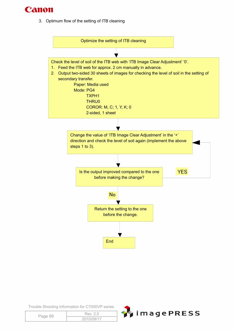
Trouble Shooting Information for C7000VP series
Page 89 Rev. 2.0 2010/09/17
3. Optimum flow of the setting of ITB cleaning
Optimize the setting of ITB cleaning
Check the level of soil of the ITB web with ‘ITB Image Clear Adjustment’ ‘0’. 1. Feed the ITB web for approx. 2 cm manually in advance. 2. Output two-sided 30 sheets of images for checking the level of soil in the setting of
secondary transfer. Paper: Media used Mode: PG4
TXPH1 THRU0 COROR: M, C; 1, Y, K; 0 2-sided, 1 sheet
Change the value of ‘ITB Image Clear Adjustment’ in the ‘+’
direction and check the level of soil again (implement the above steps 1 to 3).
Return the setting to the one before the change.
Is the output improved compared to the one before making the change?
End
YES
No
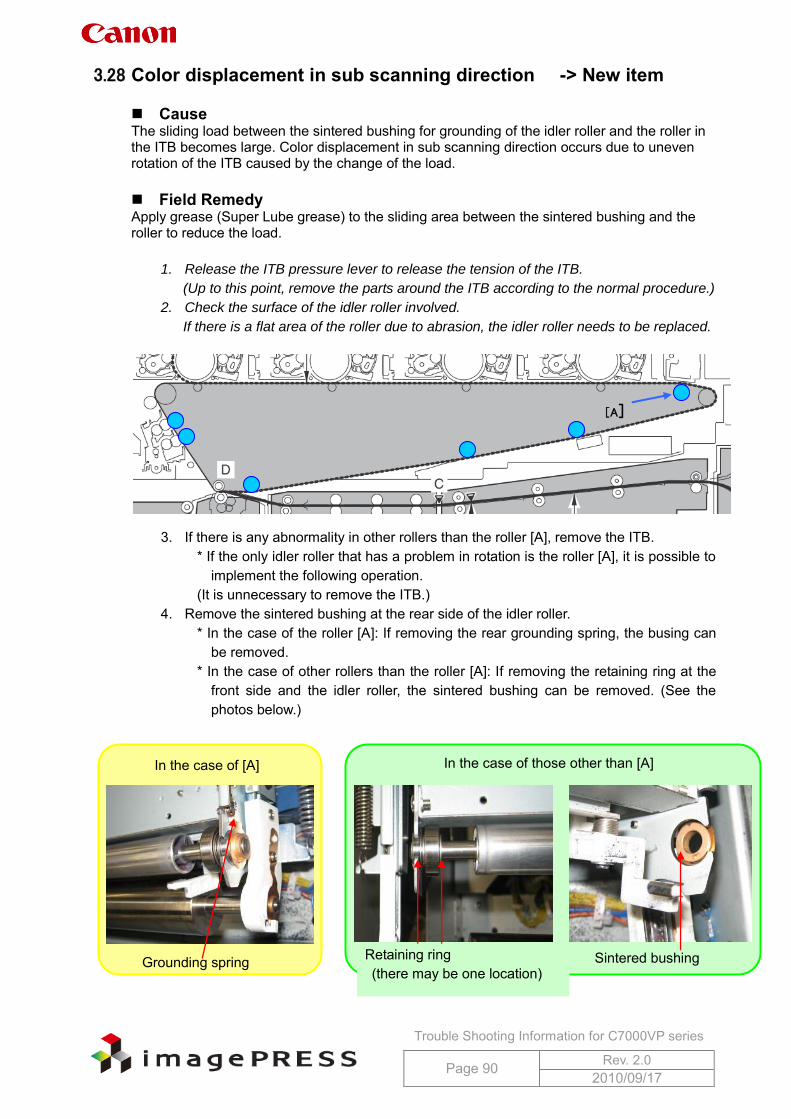
Trouble Shooting Information for C7000VP series
Page 90 Rev. 2.0 2010/09/17
3.28 Color displacement in sub scanning direction -> New item
Cause The sliding load between the sintered bushing for grounding of the idler roller and the roller in the ITB becomes large. Color displacement in sub scanning direction occurs due to uneven rotation of the ITB caused by the change of the load. Field Remedy Apply grease (Super Lube grease) to the sliding area between the sintered bushing and the roller to reduce the load.
1. Release the ITB pressure lever to release the tension of the ITB.
(Up to this point, remove the parts around the ITB according to the normal procedure.)
2. Check the surface of the idler roller involved.
If there is a flat area of the roller due to abrasion, the idler roller needs to be replaced.
3. If there is any abnormality in other rollers than the roller [A], remove the ITB. * If the only idler roller that has a problem in rotation is the roller [A], it is possible to
implement the following operation. (It is unnecessary to remove the ITB.)
4. Remove the sintered bushing at the rear side of the idler roller. * In the case of the roller [A]: If removing the rear grounding spring, the busing can
be removed. * In the case of other rollers than the roller [A]: If removing the retaining ring at the
front side and the idler roller, the sintered bushing can be removed. (See the photos below.)
[A]
In the case of [A] In the case of those other than [A]
Grounding spring Retaining ring (there may be one location)
Sintered bushing
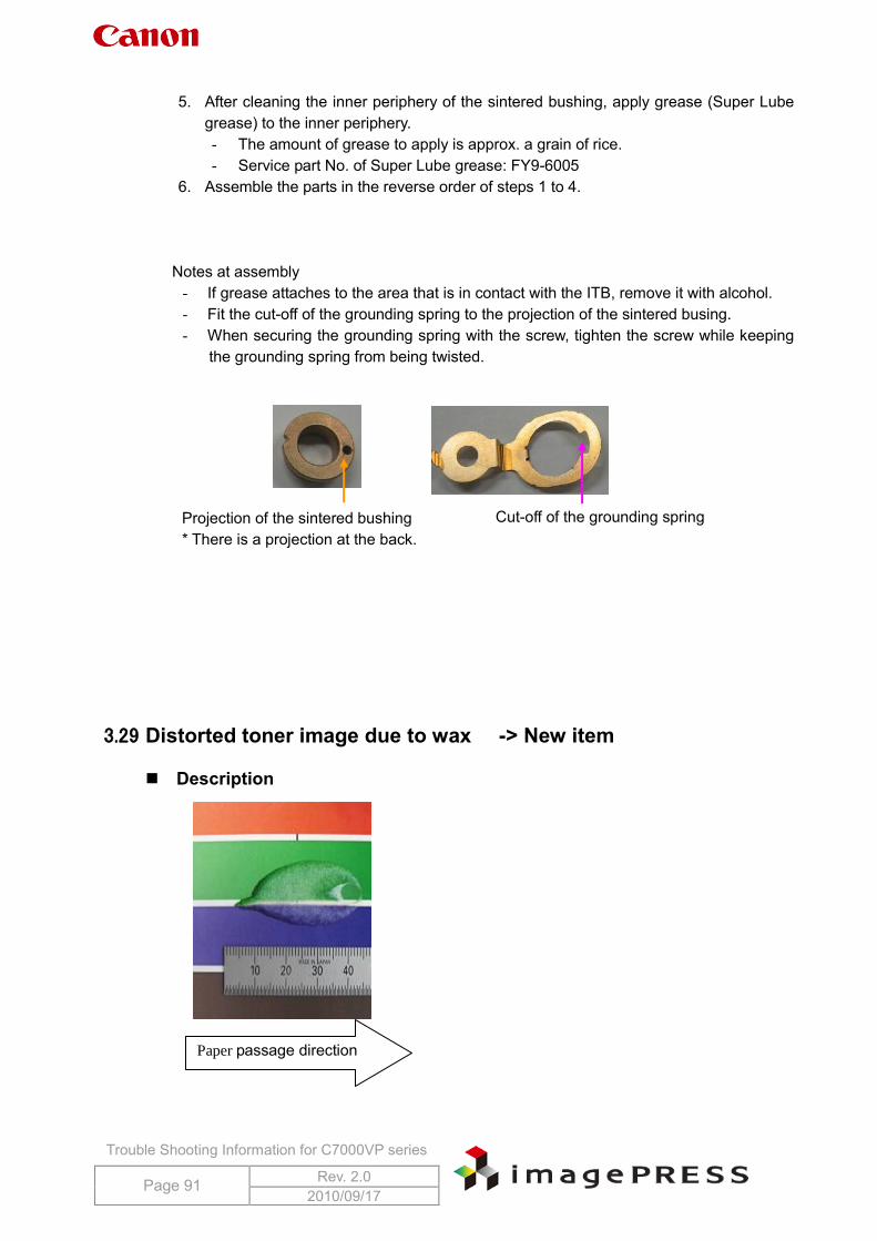
Trouble Shooting Information for C7000VP series
Page 91 Rev. 2.0 2010/09/17
5. After cleaning the inner periphery of the sintered bushing, apply grease (Super Lube
grease) to the inner periphery. - The amount of grease to apply is approx. a grain of rice. - Service part No. of Super Lube grease: FY9-6005
6. Assemble the parts in the reverse order of steps 1 to 4.
Notes at assembly - If grease attaches to the area that is in contact with the ITB, remove it with alcohol. - Fit the cut-off of the grounding spring to the projection of the sintered busing. - When securing the grounding spring with the screw, tighten the screw while keeping
the grounding spring from being twisted.
3.29 Distorted toner image due to wax -> New item
Description
Projection of the sintered bushing * There is a projection at the back.
Cut-off of the grounding spring
Paper passage direction
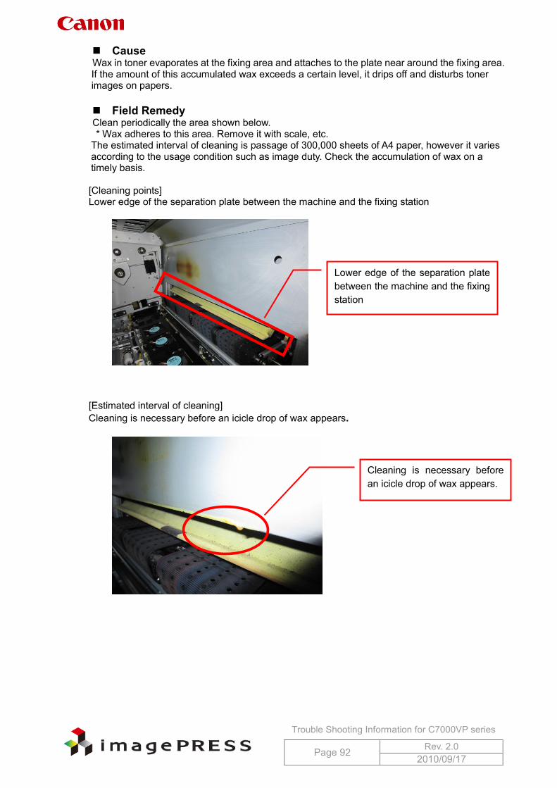
Trouble Shooting Information for C7000VP series
Page 92 Rev. 2.0 2010/09/17
Cause Wax in toner evaporates at the fixing area and attaches to the plate near around the fixing area. If the amount of this accumulated wax exceeds a certain level, it drips off and disturbs toner images on papers.
Field Remedy Clean periodically the area shown below. * Wax adheres to this area. Remove it with scale, etc.
The estimated interval of cleaning is passage of 300,000 sheets of A4 paper, however it varies according to the usage condition such as image duty. Check the accumulation of wax on a timely basis. [Cleaning points] Lower edge of the separation plate between the machine and the fixing station
[Estimated interval of cleaning] Cleaning is necessary before an icicle drop of wax appears.
Lower edge of the separation plate between the machine and the fixing station
Cleaning is necessary before an icicle drop of wax appears.
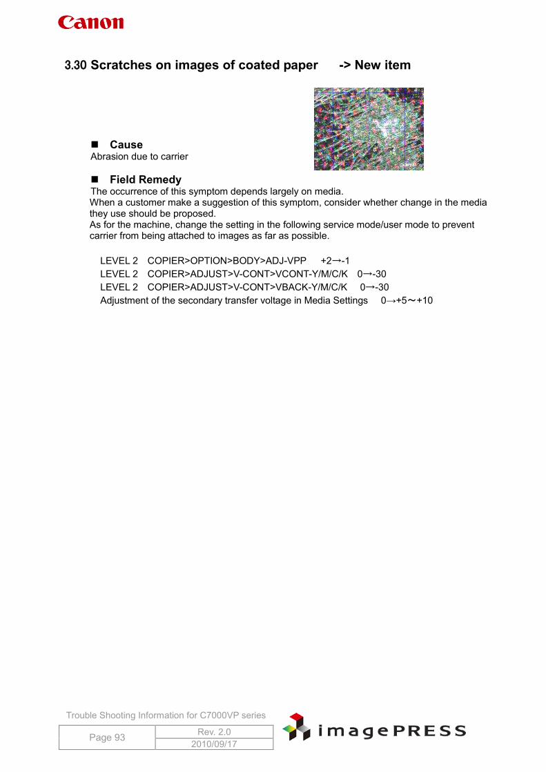
Trouble Shooting Information for C7000VP series
Page 93 Rev. 2.0 2010/09/17
3.30 Scratches on images of coated paper -> New item
Cause Abrasion due to carrier
Field Remedy The occurrence of this symptom depends largely on media. When a customer make a suggestion of this symptom, consider whether change in the media they use should be proposed. As for the machine, change the setting in the following service mode/user mode to prevent carrier from being attached to images as far as possible.
LEVEL 2 COPIER>OPTION>BODY>ADJ-VPP +2→-1 LEVEL 2 COPIER>ADJUST>V-CONT>VCONT-Y/M/C/K 0→-30 LEVEL 2 COPIER>ADJUST>V-CONT>VBACK-Y/M/C/K 0→-30 Adjustment of the secondary transfer voltage in Media Settings 0→+5~+10
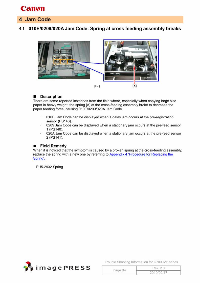
Trouble Shooting Information for C7000VP series
Page 94 Rev. 2.0 2010/09/17
4 Jam Code 4.1 010E/0209/020A Jam Code: Spring at cross feeding assembly breaks
Description There are some reported instances from the field where, especially when copying large size paper in heavy weight, the spring [A] at the cross-feeding assembly broke to decrease the paper feeding force, causing 010E/0209/020A Jam Code.
010E Jam Code can be displayed when a delay jam occurs at the pre-registration sensor (PS146).
0209 Jam Code can be displayed when a stationary jam occurs at the pre-feed sensor 1 (PS140).
020A Jam Code can be displayed when a stationary jam occurs at the pre-feed sensor 2 (PS141).
Field Remedy When it is noticed that the symptom is caused by a broken spring at the cross-feeding assembly, replace the spring with a new one by referring to Appendix 4 ‘Procedure for Replacing the Spring’.
FU5-2932 Spring
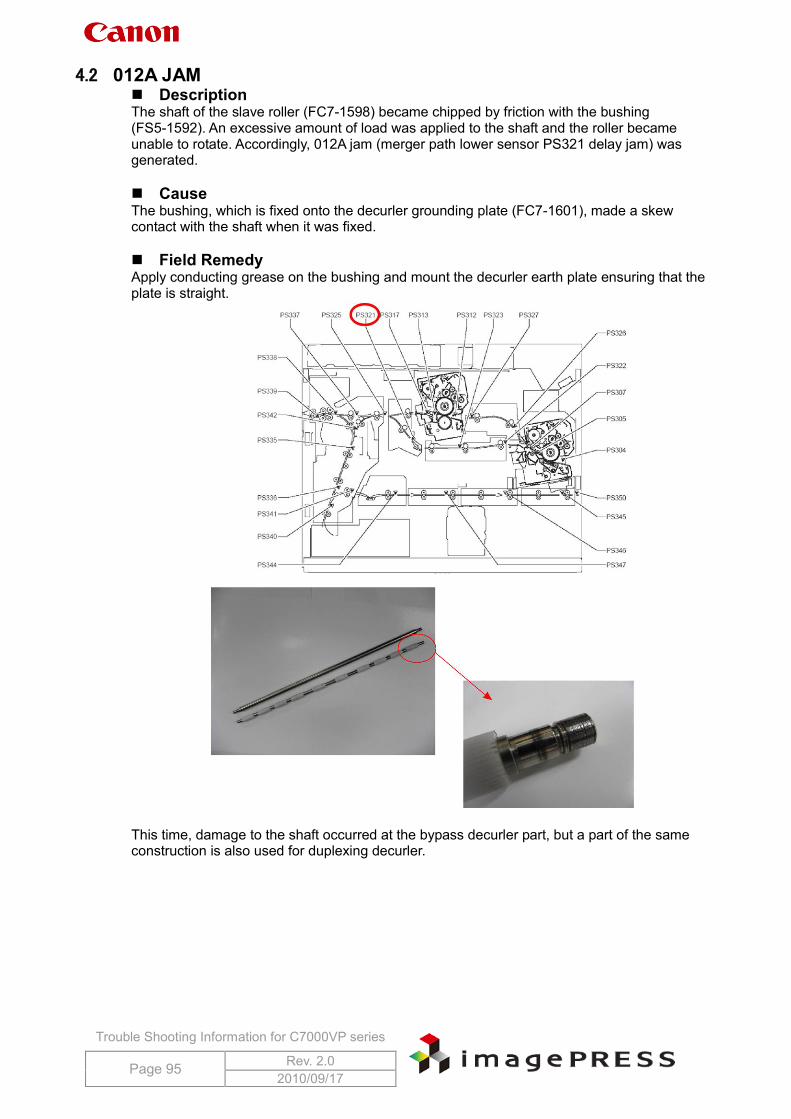
Trouble Shooting Information for C7000VP series
Page 95 Rev. 2.0 2010/09/17
4.2 012A JAM Description The shaft of the slave roller (FC7-1598) became chipped by friction with the bushing (FS5-1592). An excessive amount of load was applied to the shaft and the roller became unable to rotate. Accordingly, 012A jam (merger path lower sensor PS321 delay jam) was generated. Cause The bushing, which is fixed onto the decurler grounding plate (FC7-1601), made a skew contact with the shaft when it was fixed. Field Remedy Apply conducting grease on the bushing and mount the decurler earth plate ensuring that the plate is straight.
This time, damage to the shaft occurred at the bypass decurler part, but a part of the same construction is also used for duplexing decurler.
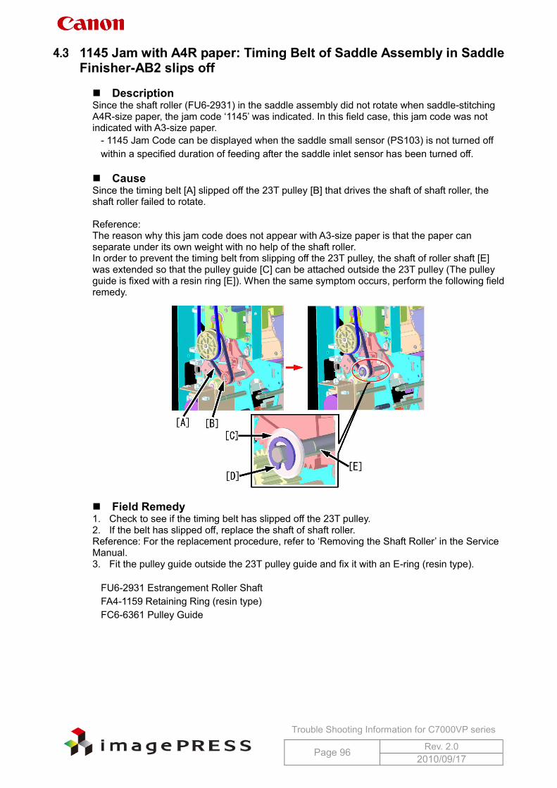
Trouble Shooting Information for C7000VP series
Page 96 Rev. 2.0 2010/09/17
4.3 1145 Jam with A4R paper: Timing Belt of Saddle Assembly in Saddle Finisher-AB2 slips off
Description Since the shaft roller (FU6-2931) in the saddle assembly did not rotate when saddle-stitching A4R-size paper, the jam code ‘1145’ was indicated. In this field case, this jam code was not indicated with A3-size paper.
- 1145 Jam Code can be displayed when the saddle small sensor (PS103) is not turned off within a specified duration of feeding after the saddle inlet sensor has been turned off.
Cause Since the timing belt [A] slipped off the 23T pulley [B] that drives the shaft of shaft roller, the shaft roller failed to rotate. Reference: The reason why this jam code does not appear with A3-size paper is that the paper can separate under its own weight with no help of the shaft roller. In order to prevent the timing belt from slipping off the 23T pulley, the shaft of roller shaft [E] was extended so that the pulley guide [C] can be attached outside the 23T pulley (The pulley guide is fixed with a resin ring [E]). When the same symptom occurs, perform the following field remedy.
Field Remedy 1. Check to see if the timing belt has slipped off the 23T pulley. 2. If the belt has slipped off, replace the shaft of shaft roller. Reference: For the replacement procedure, refer to ‘Removing the Shaft Roller’ in the Service Manual. 3. Fit the pulley guide outside the 23T pulley guide and fix it with an E-ring (resin type).
FU6-2931 Estrangement Roller Shaft FA4-1159 Retaining Ring (resin type) FC6-6361 Pulley Guide
Trouble Shooting Information for C7000VP series
Page 97 Rev. 2.0 2010/09/17
4.4 0114 JAM Description When using thin paper like 64g NPI high grade, 0114 and 0115 JAM occurred frequently with duplex print. Thin paper does not have stiffness and fundamentally is a severe condition to this symptom. Field Remedy Change the setting to paper database ‘Thin paper’ and monitor for improvement. Clean the first fixing inlet guide with alcohol.
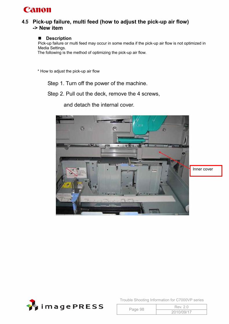
Trouble Shooting Information for C7000VP series
Page 98 Rev. 2.0 2010/09/17
4.5 Pick-up failure, multi feed (how to adjust the pick-up air flow) -> New item
Description Pick-up failure or multi feed may occur in some media if the pick-up air flow is not optimized in Media Settings. The following is the method of optimizing the pick-up air flow. * How to adjust the pick-up air flow
Step 1. Turn off the power of the machine.
Step 2. Pull out the deck, remove the 4 screws,
and detach the internal cover.
Inner cover
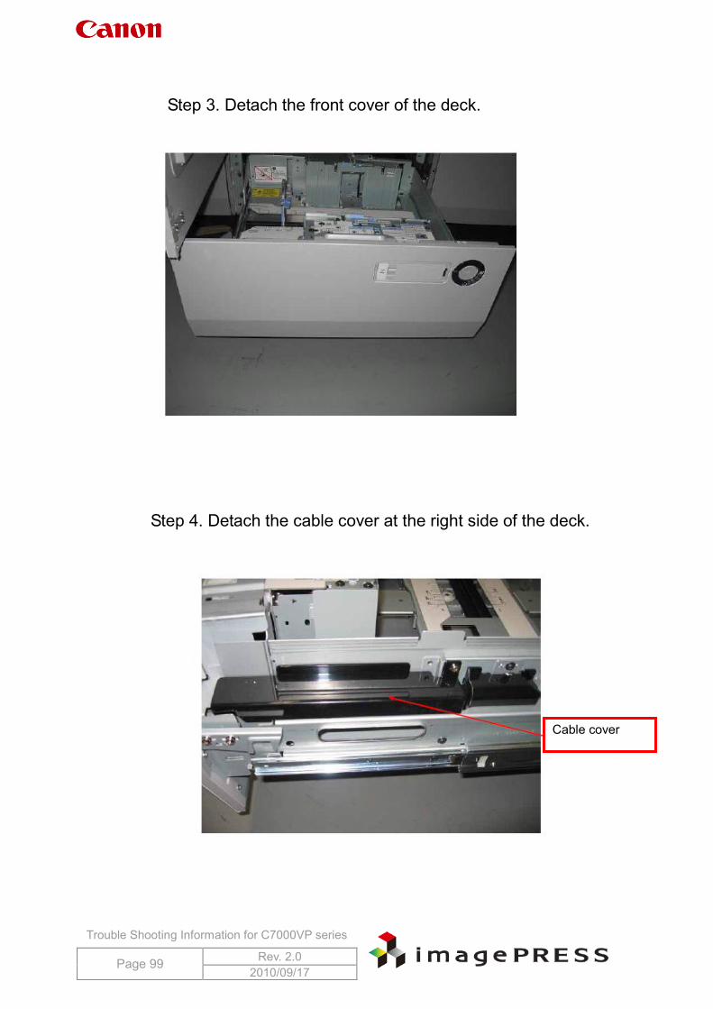
Trouble Shooting Information for C7000VP series
Page 99 Rev. 2.0 2010/09/17
Step 3. Detach the front cover of the deck.
Step 4. Detach the cable cover at the right side of the deck.
Cable cover
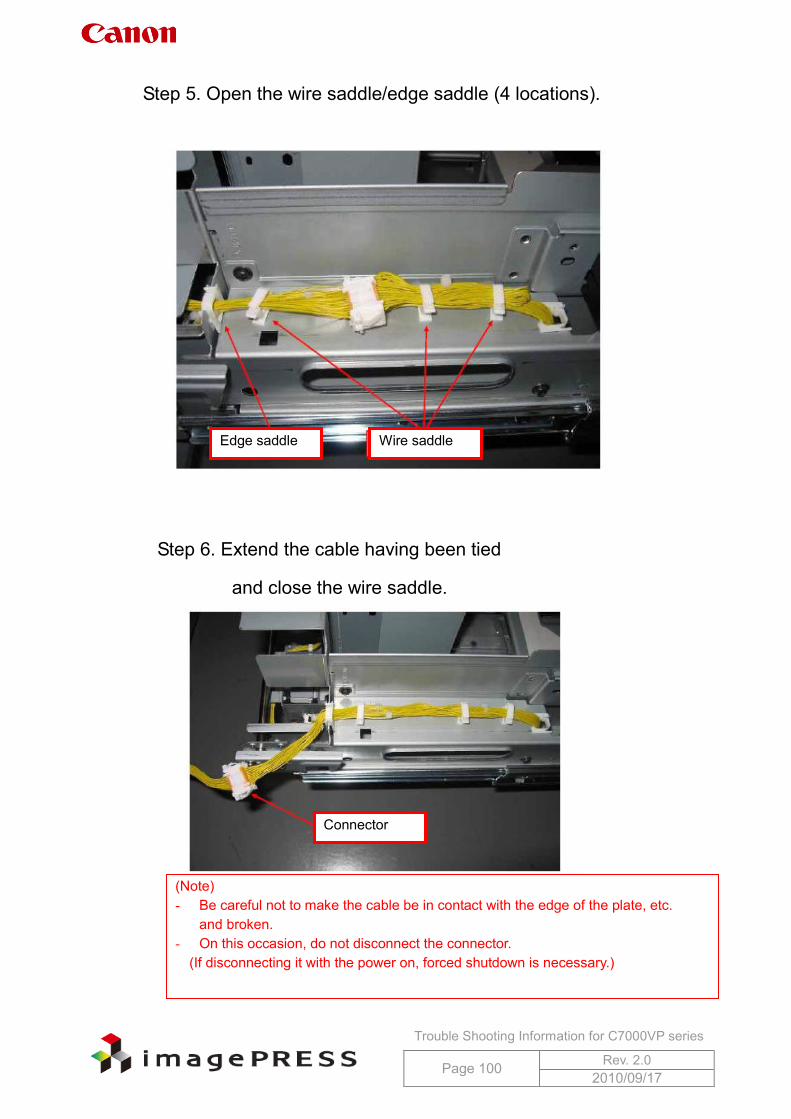
Trouble Shooting Information for C7000VP series
Page 100 Rev. 2.0 2010/09/17
Step 5. Open the wire saddle/edge saddle (4 locations).
Step 6. Extend the cable having been tied
and close the wire saddle.
(Note) - Be careful not to make the cable be in contact with the edge of the plate, etc.
and broken. - On this occasion, do not disconnect the connector.
(If disconnecting it with the power on, forced shutdown is necessary.)
Edge saddle Wire saddle
Connector
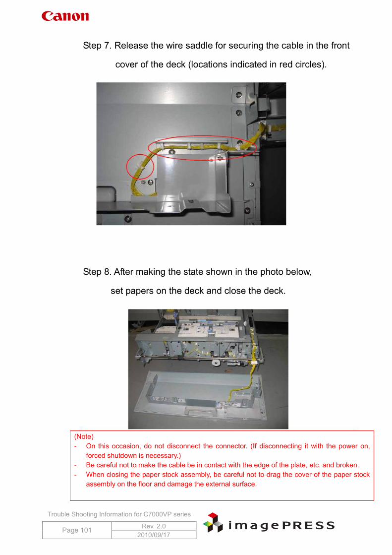
Trouble Shooting Information for C7000VP series
Page 101 Rev. 2.0 2010/09/17
Step 7. Release the wire saddle for securing the cable in the front
cover of the deck (locations indicated in red circles).
Step 8. After making the state shown in the photo below,
set papers on the deck and close the deck.
.
(Note) - On this occasion, do not disconnect the connector. (If disconnecting it with the power on,
forced shutdown is necessary.) - Be careful not to make the cable be in contact with the edge of the plate, etc. and broken. - When closing the paper stock assembly, be careful not to drag the cover of the paper stock
assembly on the floor and damage the external surface.
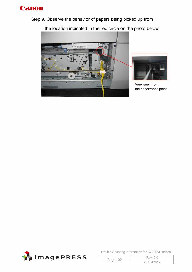
Trouble Shooting Information for C7000VP series
Page 102 Rev. 2.0 2010/09/17
Step 9. Observe the behavior of papers being picked up from
the location indicated in the red circle on the photo below.
View seen from the observance point
.
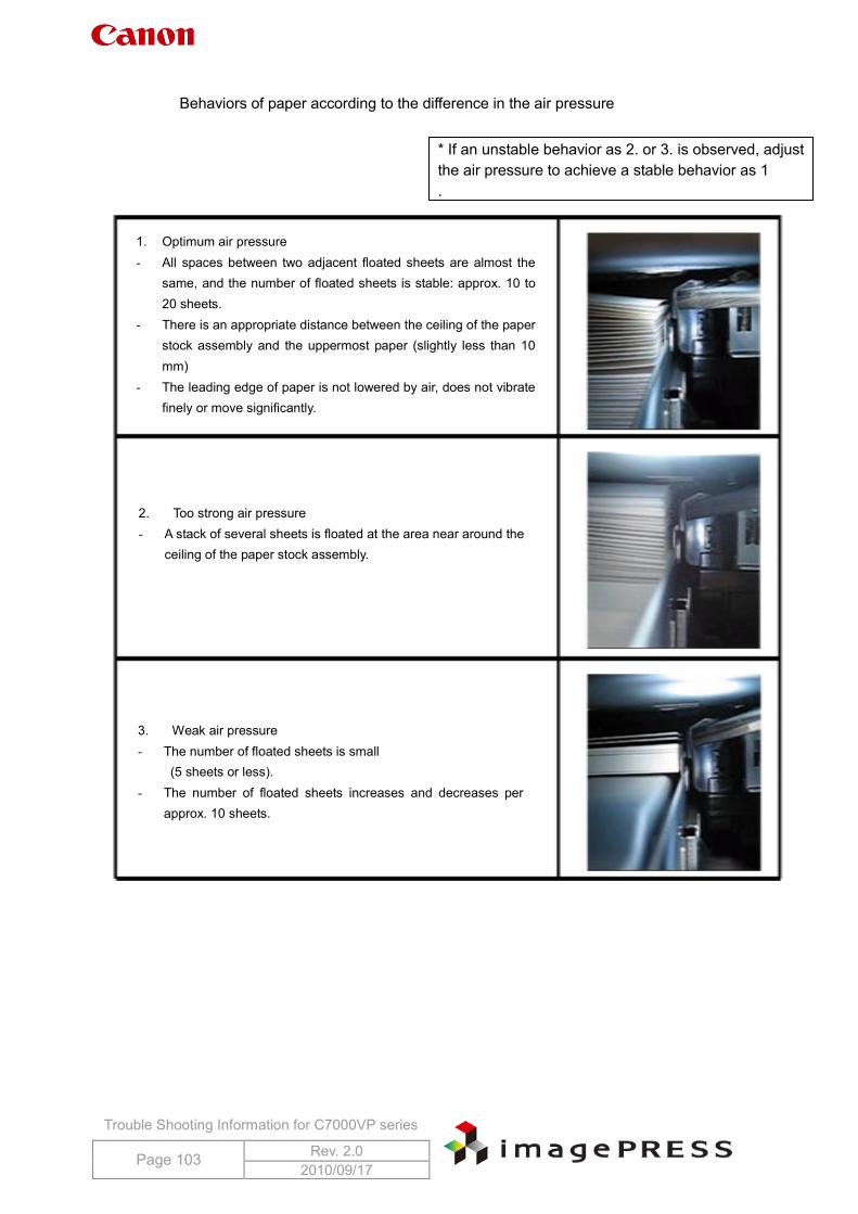
Trouble Shooting Information for C7000VP series
Page 103 Rev. 2.0 2010/09/17
Behaviors of paper according to the difference in the air pressure
* If an unstable behavior as 2. or 3. is observed, adjust the air pressure to achieve a stable behavior as 1 .
1. Optimum air pressure - All spaces between two adjacent floated sheets are almost the
same, and the number of floated sheets is stable: approx. 10 to 20 sheets.
- There is an appropriate distance between the ceiling of the paper stock assembly and the uppermost paper (slightly less than 10 mm)
- The leading edge of paper is not lowered by air, does not vibrate finely or move significantly.
2. Too strong air pressure - A stack of several sheets is floated at the area near around the
ceiling of the paper stock assembly.
3. Weak air pressure - The number of floated sheets is small
(5 sheets or less). - The number of floated sheets increases and decreases per
approx. 10 sheets.
Trouble Shooting Information for C7000VP series
Page 104 Rev. 2.0 2010/09/17
5 Specification-related issues 5.1 Description on fixing roller refresh operation and its execution
timing Description There is a case where the lead edge (cut edge) of paper hit the fixing roller and, thus, causes shiny lines (1mm to 1.5mm wide) in the main scanning direction at the fixing roller intervals. To prevent this, this machine has a control sequence for automatically refreshing the fixing roller surface. a. Execution timing
a-1. At time of cleaning the corona wire a-2. At time of changing the paper size (from small to large) a-3. At time of post rotation
b. Execution condition The refreshing operation is executed when the media size counter this machine computes reaches the threshold value.
c. Change of time spent for the refreshing operation Changing the setting in user mode > System Settings > Device Management Settings > Fixing Roller Auto Refresh Level will change the length of time spent for refreshing operation. Changing the setting of this mode will also ease the execution condition of the refreshing operation. c-1. Default value '0': perform the refreshing operation for about 30 sec to 60 sec. (The time spent for the operation changes depending on the media size counter.) c-2. Adjustment range: between '-5' (30 sec) to '+5' (330 sec). Changing the value by '1' will increase/decrease the length of time spent for the operation by 30 sec. Selecting a positive value will increase the length of time spent for one operation while a negative value will decrease it. If the value '-5' is selected, the operation is not executed.
d. Conditions other than the above d-1. Interruption refreshing based on the video counter reading (1 sec) d-2. Refreshing at startup. (3 sec) For these conditions, changing the fixing roller auto refresh level setting will change a parameter (the threshold value of video count), consequently changing the timing at which this machine starts the refreshing operation. However, if the setting value is between '-5' and '-1', the operation is not executed.
Note: No matter how many sheets of SRA3 or 13x19 size paper are fed, as papers larger than these sizes are not used, shiny lines due to paper lint do not occur. Therefore, the media size counter, the parameter for roller refreshing, does not increase.
Trouble Shooting Information for C7000VP series
Page 105 Rev. 2.0 2010/09/17
5.2 Specifications for staple capacity of Finisher-AB1/AB2 Description The following are specifications for staple capacity of Finisher-AB1/AB2 by basis weight of paper (both small and large sizes).
Weight of paper # of sheets applicable (Small size / Large size) 64g to 80g 100sh / 50sh over 80g to 81.4g 80sh / 50sh over 81.4g to 105g: 60sh / 30sh over 105g to 200g: 20sh / 10sh over 200g to 300g: Cover and back cover only
Note:
- Thickness of stack has to be less than 11mm for small size, and less than 5.5mm for large size. - Length of paper in feeding direction has to be as follows. For large size: 216.1mm to 482.7mm (e.g. 13x19, 12x18, SRA3, A3, B4, A4R, B5R,
LDR, LGL, LTRR, EXER) For small size: shorter then 216mm (e.g. A4, B5, A5R, LTR, EXE, STMTR)
Reference: Although the staple capacity of the aforementioned Finisher units is specified like the above, on requests from the field, the units were so designed that they staple more than the number of sheets described above with regard to all basis weights in case the total number of sheets to be stapled is set within 100 sheets. But, please be informed that a problem may occur when the units staple more than the number specified above.
5.3 Number of sheets and size specification for saddle stitching Description - Paper size applicable for saddle stitching:
12 x 18, SRA3 (320 x 450), A3, B4, A4R, LDR, LTRR, LGL - Basis weight:
Inner sheets: 64 to 200g/mx2 Cover: 64 to 300g/x2
- Maximum number of sheets for binding: 20 sheets (Inner sheets (64 to 80g/mx2) 19 sheets + Cover (64 to 300g/mx2) 1 sheet
Plain paper 64 to 80g/mx2 2 to 20 sheets (incl. cover) 81 to 105g/mx2 2 to 15 sheets (incl. cover) Over 105 to 200g/mx2 2 to 5 sheets (incl. cover)
Coated paper 80 to 81.4g/mx2 2 to 15 sheets (incl. cover) 81.5 to 105g/mx2 2 to 10 sheets (incl. cover) Over 105 to 200g/mx2 2 to 5 sheets (incl. cover)
Trouble Shooting Information for C7000VP series
Page 106 Rev. 2.0 2010/09/17
5.4 When uploading DC Controller data with SST, ‘SramDCON’ does not appear on SST screen
Description ‘SramDCON’ and ‘SramRCON’ files are displayed on the SST screen only when this machine is started in normal mode. If this machine is started in safe mode, these files do not appear on the SST screen. Field Remedy While pressing down '1' and '7' keys, turn ON the main power switch. Then, in service mode > COPIER > Function > SYSTEM, select [DOWNLOAD] to enter the download mode, and then upload the data with SST.
5.5 Description of features of Function Expansion PCB on DC Controller PCB 1-2
Description The Function Expansion PCB is a sub board that is screwed on the DC Controller PCB 1-2. When it is replaced, there is no need to make adjustments. It controls the following:
Patch image detection sensor Primary high voltage Pre-exposure lamp in the drum cleaner unit
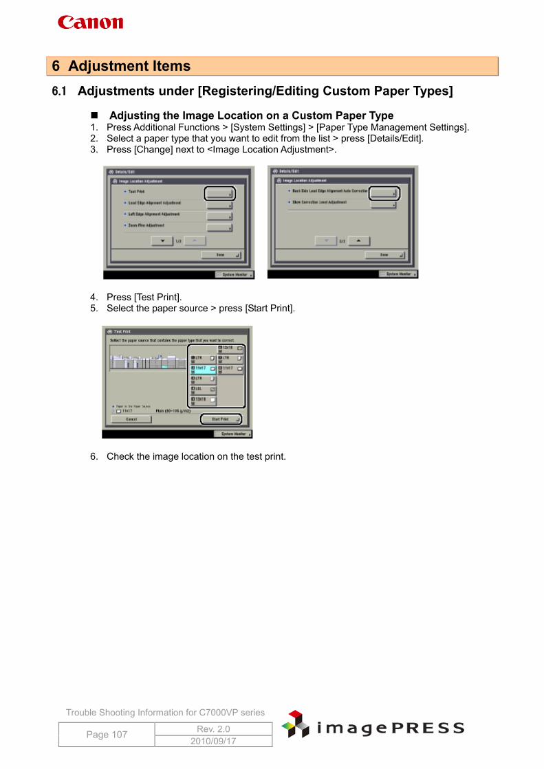
Trouble Shooting Information for C7000VP series
Page 107 Rev. 2.0 2010/09/17
6 Adjustment Items 6.1 Adjustments under [Registering/Editing Custom Paper Types]
Adjusting the Image Location on a Custom Paper Type 1. Press Additional Functions > [System Settings] > [Paper Type Management Settings]. 2. Select a paper type that you want to edit from the list > press [Details/Edit]. 3. Press [Change] next to <Image Location Adjustment>.
4. Press [Test Print]. 5. Select the paper source > press [Start Print].
6. Check the image location on the test print.
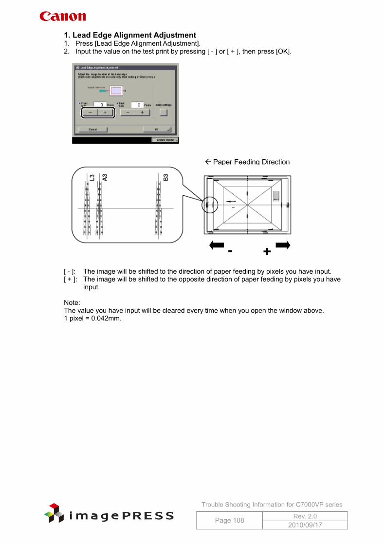
Trouble Shooting Information for C7000VP series
Page 108 Rev. 2.0 2010/09/17
1. Lead Edge Alignment Adjustment 1. Press [Lead Edge Alignment Adjustment]. 2. Input the value on the test print by pressing [ - ] or [ + ], then press [OK].
[ - ]: The image will be shifted to the direction of paper feeding by pixels you have input. [ + ]: The image will be shifted to the opposite direction of paper feeding by pixels you have
input. Note: The value you have input will be cleared every time when you open the window above. 1 pixel = 0.042mm.
Paper Feeding Direction
+ -
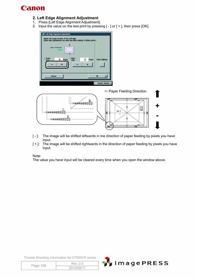
Trouble Shooting Information for C7000VP series
Page 109 Rev. 2.0 2010/09/17
2. Left Edge Alignment Adjustment 1. Press [Left Edge Alignment Adjustment]. 2. Input the value on the test print by pressing [ - ] or [ + ], then press [OK].
[ - ]: The image will be shifted leftwards in the direction of paper feeding by pixels you have
input. [ + ]: The image will be shifted rightwards in the direction of paper feeding by pixels you have
input. Note: The value you have input will be cleared every time when you open the window above.
+ -
<- Paper Feeding Direction
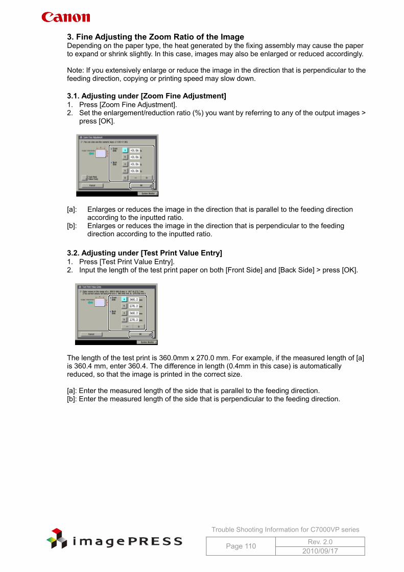
Trouble Shooting Information for C7000VP series
Page 110 Rev. 2.0 2010/09/17
3. Fine Adjusting the Zoom Ratio of the Image Depending on the paper type, the heat generated by the fixing assembly may cause the paper to expand or shrink slightly. In this case, images may also be enlarged or reduced accordingly. Note: If you extensively enlarge or reduce the image in the direction that is perpendicular to the feeding direction, copying or printing speed may slow down. 3.1. Adjusting under [Zoom Fine Adjustment] 1. Press [Zoom Fine Adjustment]. 2. Set the enlargement/reduction ratio (%) you want by referring to any of the output images >
press [OK].
[a]: Enlarges or reduces the image in the direction that is parallel to the feeding direction
according to the inputted ratio. [b]: Enlarges or reduces the image in the direction that is perpendicular to the feeding
direction according to the inputted ratio.
3.2. Adjusting under [Test Print Value Entry] 1. Press [Test Print Value Entry]. 2. Input the length of the test print paper on both [Front Side] and [Back Side] > press [OK].
The length of the test print is 360.0mm x 270.0 mm. For example, if the measured length of [a] is 360.4 mm, enter 360.4. The difference in length (0.4mm in this case) is automatically reduced, so that the image is printed in the correct size. [a]: Enter the measured length of the side that is parallel to the feeding direction. [b]: Enter the measured length of the side that is perpendicular to the feeding direction.
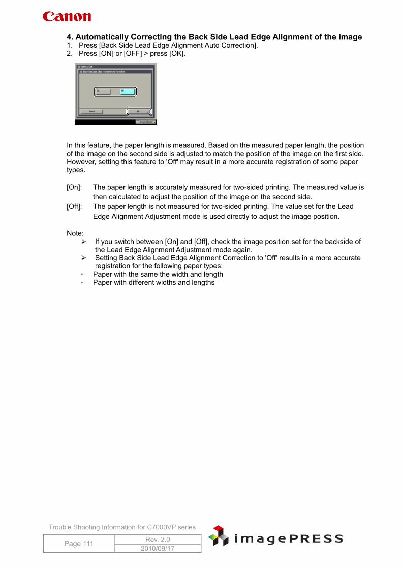
Trouble Shooting Information for C7000VP series
Page 111 Rev. 2.0 2010/09/17
4. Automatically Correcting the Back Side Lead Edge Alignment of the Image 1. Press [Back Side Lead Edge Alignment Auto Correction]. 2. Press [ON] or [OFF] > press [OK].
In this feature, the paper length is measured. Based on the measured paper length, the position of the image on the second side is adjusted to match the position of the image on the first side. However, setting this feature to 'Off' may result in a more accurate registration of some paper types. [On]: The paper length is accurately measured for two-sided printing. The measured value is
then calculated to adjust the position of the image on the second side. [Off]: The paper length is not measured for two-sided printing. The value set for the Lead
Edge Alignment Adjustment mode is used directly to adjust the image position. Note:
If you switch between [On] and [Off], check the image position set for the backside of the Lead Edge Alignment Adjustment mode again.
Setting Back Side Lead Edge Alignment Correction to 'Off' results in a more accurate registration for the following paper types:
Paper with the same the width and length Paper with different widths and lengths
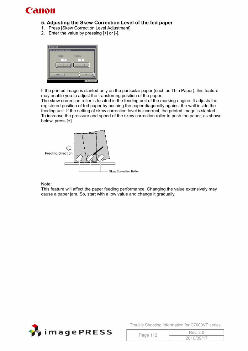
Trouble Shooting Information for C7000VP series
Page 112 Rev. 2.0 2010/09/17
5. Adjusting the Skew Correction Level of the fed paper 1. Press [Skew Correction Level Adjustment]. 2. Enter the value by pressing [+] or [-].
If the printed image is slanted only on the particular paper (such as Thin Paper), this feature may enable you to adjust the transferring position of the paper. The skew correction roller is located in the feeding unit of the marking engine. It adjusts the registered position of fed paper by pushing the paper diagonally against the wall inside the feeding unit. If the setting of skew correction level is incorrect, the printed image is slanted. To increase the pressure and speed of the skew correction roller to push the paper, as shown below, press [+].
Note: This feature will affect the paper feeding performance. Changing the value extensively may cause a paper jam. So, start with a low value and change it gradually.
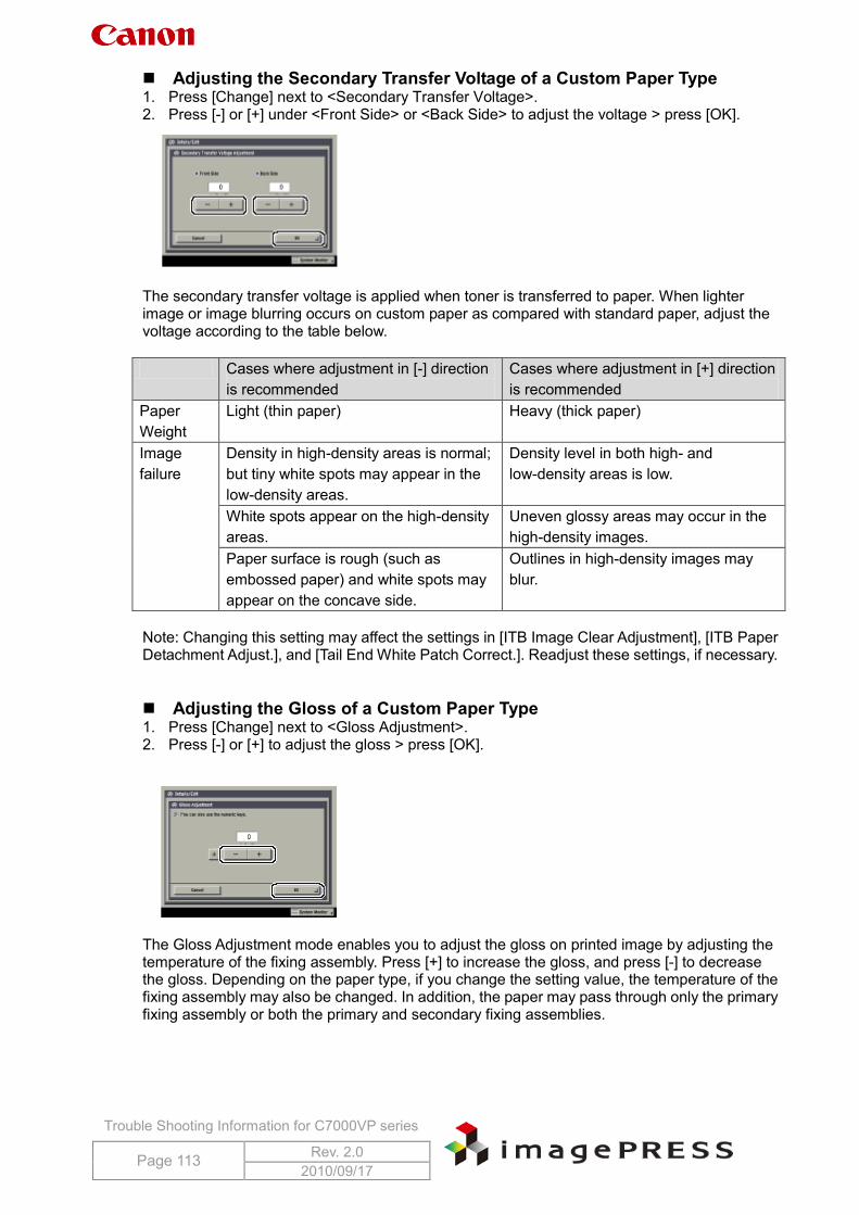
Trouble Shooting Information for C7000VP series
Page 113 Rev. 2.0 2010/09/17
Adjusting the Secondary Transfer Voltage of a Custom Paper Type 1. Press [Change] next to <Secondary Transfer Voltage>. 2. Press [-] or [+] under <Front Side> or <Back Side> to adjust the voltage > press [OK].
The secondary transfer voltage is applied when toner is transferred to paper. When lighter image or image blurring occurs on custom paper as compared with standard paper, adjust the voltage according to the table below. Cases where adjustment in [-] direction
is recommended Cases where adjustment in [+] direction is recommended
Paper Weight
Light (thin paper) Heavy (thick paper)
Image failure
Density in high-density areas is normal; but tiny white spots may appear in the low-density areas.
Density level in both high- and low-density areas is low.
White spots appear on the high-density areas.
Uneven glossy areas may occur in the high-density images.
Paper surface is rough (such as embossed paper) and white spots may appear on the concave side.
Outlines in high-density images may blur.
Note: Changing this setting may affect the settings in [ITB Image Clear Adjustment], [ITB Paper Detachment Adjust.], and [Tail End White Patch Correct.]. Readjust these settings, if necessary. Adjusting the Gloss of a Custom Paper Type 1. Press [Change] next to <Gloss Adjustment>. 2. Press [-] or [+] to adjust the gloss > press [OK].
The Gloss Adjustment mode enables you to adjust the gloss on printed image by adjusting the temperature of the fixing assembly. Press [+] to increase the gloss, and press [-] to decrease the gloss. Depending on the paper type, if you change the setting value, the temperature of the fixing assembly may also be changed. In addition, the paper may pass through only the primary fixing assembly or both the primary and secondary fixing assemblies.
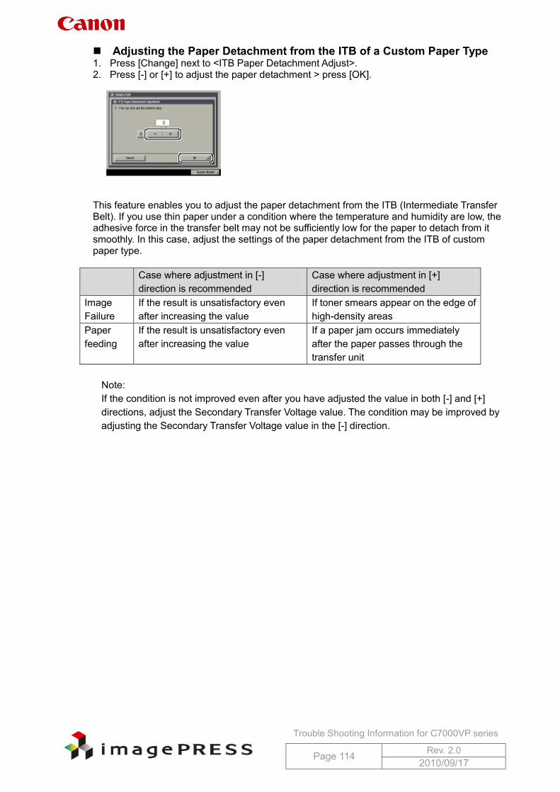
Trouble Shooting Information for C7000VP series
Page 114 Rev. 2.0 2010/09/17
Adjusting the Paper Detachment from the ITB of a Custom Paper Type 1. Press [Change] next to <ITB Paper Detachment Adjust>. 2. Press [-] or [+] to adjust the paper detachment > press [OK].
This feature enables you to adjust the paper detachment from the ITB (Intermediate Transfer Belt). If you use thin paper under a condition where the temperature and humidity are low, the adhesive force in the transfer belt may not be sufficiently low for the paper to detach from it smoothly. In this case, adjust the settings of the paper detachment from the ITB of custom paper type.
Case where adjustment in [-] direction is recommended
Case where adjustment in [+] direction is recommended
Image Failure
If the result is unsatisfactory even after increasing the value
If toner smears appear on the edge of high-density areas
Paper feeding
If the result is unsatisfactory even after increasing the value
If a paper jam occurs immediately after the paper passes through the transfer unit
Note: If the condition is not improved even after you have adjusted the value in both [-] and [+] directions, adjust the Secondary Transfer Voltage value. The condition may be improved by adjusting the Secondary Transfer Voltage value in the [-] direction.
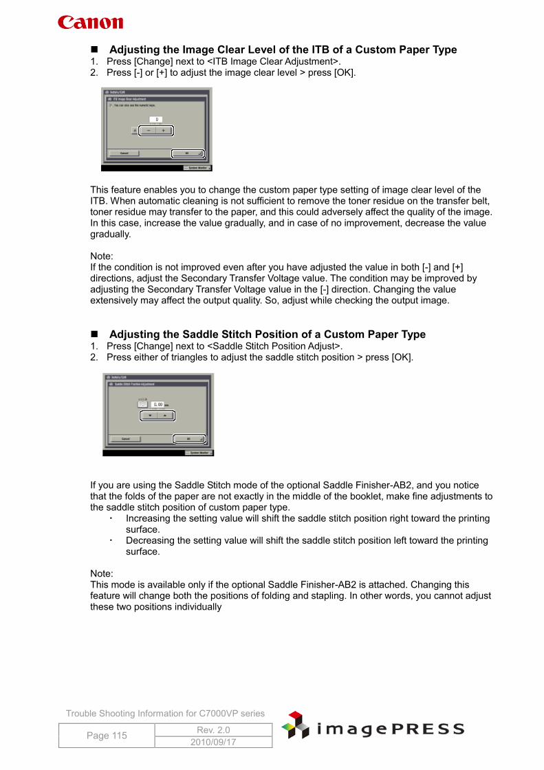
Trouble Shooting Information for C7000VP series
Page 115 Rev. 2.0 2010/09/17
Adjusting the Image Clear Level of the ITB of a Custom Paper Type 1. Press [Change] next to <ITB Image Clear Adjustment>. 2. Press [-] or [+] to adjust the image clear level > press [OK].
This feature enables you to change the custom paper type setting of image clear level of the ITB. When automatic cleaning is not sufficient to remove the toner residue on the transfer belt, toner residue may transfer to the paper, and this could adversely affect the quality of the image. In this case, increase the value gradually, and in case of no improvement, decrease the value gradually. Note: If the condition is not improved even after you have adjusted the value in both [-] and [+] directions, adjust the Secondary Transfer Voltage value. The condition may be improved by adjusting the Secondary Transfer Voltage value in the [-] direction. Changing the value extensively may affect the output quality. So, adjust while checking the output image. Adjusting the Saddle Stitch Position of a Custom Paper Type 1. Press [Change] next to <Saddle Stitch Position Adjust>. 2. Press either of triangles to adjust the saddle stitch position > press [OK].
If you are using the Saddle Stitch mode of the optional Saddle Finisher-AB2, and you notice that the folds of the paper are not exactly in the middle of the booklet, make fine adjustments to the saddle stitch position of custom paper type.
Increasing the setting value will shift the saddle stitch position right toward the printing surface.
Decreasing the setting value will shift the saddle stitch position left toward the printing surface.
Note: This mode is available only if the optional Saddle Finisher-AB2 is attached. Changing this feature will change both the positions of folding and stapling. In other words, you cannot adjust these two positions individually
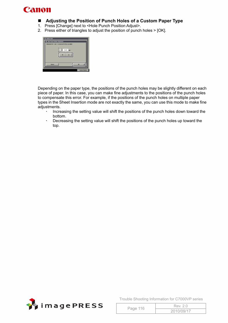
Trouble Shooting Information for C7000VP series
Page 116 Rev. 2.0 2010/09/17
Adjusting the Position of Punch Holes of a Custom Paper Type 1. Press [Change] next to <Hole Punch Position Adjust>. 2. Press either of triangles to adjust the position of punch holes > [OK].
Depending on the paper type, the positions of the punch holes may be slightly different on each piece of paper. In this case, you can make fine adjustments to the positions of the punch holes to compensate this error. For example, if the positions of the punch holes on multiple paper types in the Sheet Insertion mode are not exactly the same, you can use this mode to make fine adjustments.
Increasing the setting value will shift the positions of the punch holes down toward the bottom.
Decreasing the setting value will shift the positions of the punch holes up toward the top.
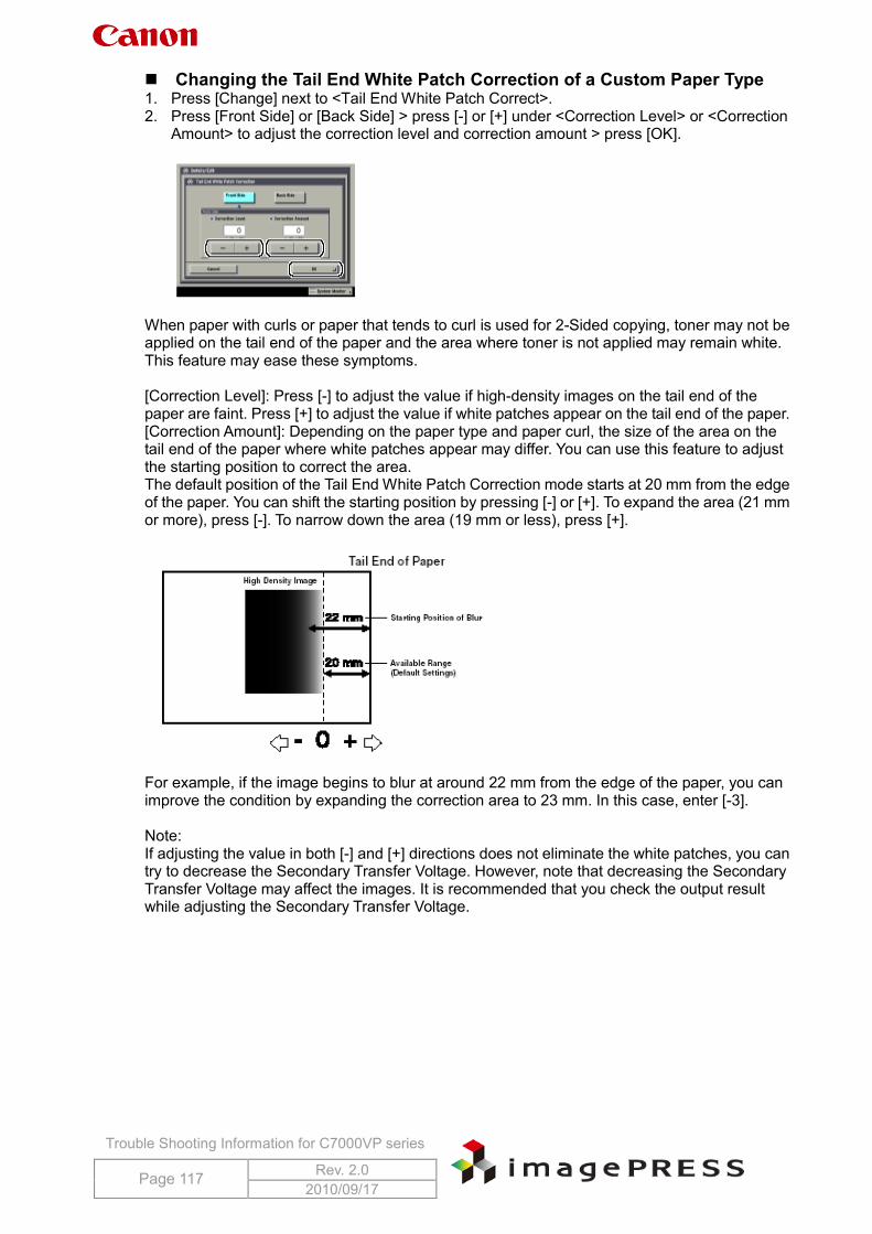
Trouble Shooting Information for C7000VP series
Page 117 Rev. 2.0 2010/09/17
Changing the Tail End White Patch Correction of a Custom Paper Type 1. Press [Change] next to <Tail End White Patch Correct>. 2. Press [Front Side] or [Back Side] > press [-] or [+] under <Correction Level> or <Correction
Amount> to adjust the correction level and correction amount > press [OK].
When paper with curls or paper that tends to curl is used for 2-Sided copying, toner may not be applied on the tail end of the paper and the area where toner is not applied may remain white. This feature may ease these symptoms. [Correction Level]: Press [-] to adjust the value if high-density images on the tail end of the paper are faint. Press [+] to adjust the value if white patches appear on the tail end of the paper. [Correction Amount]: Depending on the paper type and paper curl, the size of the area on the tail end of the paper where white patches appear may differ. You can use this feature to adjust the starting position to correct the area. The default position of the Tail End White Patch Correction mode starts at 20 mm from the edge of the paper. You can shift the starting position by pressing [-] or [+]. To expand the area (21 mm or more), press [-]. To narrow down the area (19 mm or less), press [+].
For example, if the image begins to blur at around 22 mm from the edge of the paper, you can improve the condition by expanding the correction area to 23 mm. In this case, enter [-3]. Note: If adjusting the value in both [-] and [+] directions does not eliminate the white patches, you can try to decrease the Secondary Transfer Voltage. However, note that decreasing the Secondary Transfer Voltage may affect the images. It is recommended that you check the output result while adjusting the Secondary Transfer Voltage.
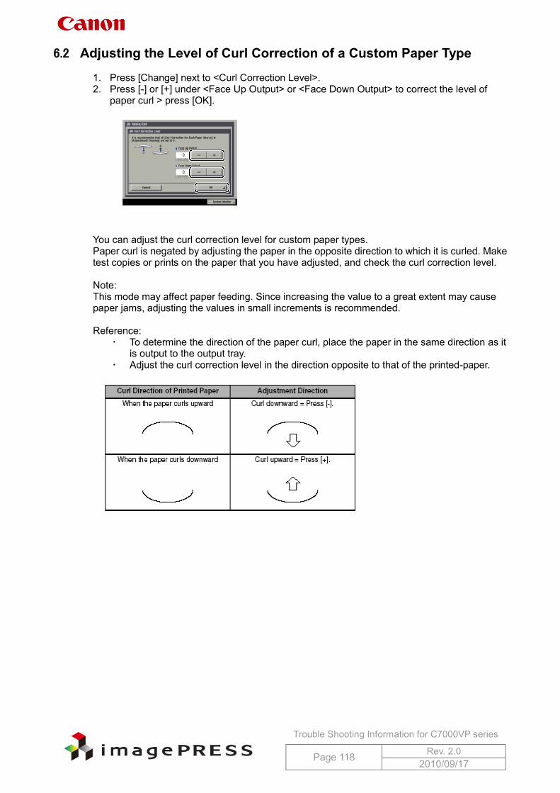
Trouble Shooting Information for C7000VP series
Page 118 Rev. 2.0 2010/09/17
6.2 Adjusting the Level of Curl Correction of a Custom Paper Type 1. Press [Change] next to <Curl Correction Level>. 2. Press [-] or [+] under <Face Up Output> or <Face Down Output> to correct the level of
paper curl > press [OK].
You can adjust the curl correction level for custom paper types. Paper curl is negated by adjusting the paper in the opposite direction to which it is curled. Make test copies or prints on the paper that you have adjusted, and check the curl correction level. Note: This mode may affect paper feeding. Since increasing the value to a great extent may cause paper jams, adjusting the values in small increments is recommended. Reference:
To determine the direction of the paper curl, place the paper in the same direction as it is output to the output tray.
Adjust the curl correction level in the direction opposite to that of the printed-paper.
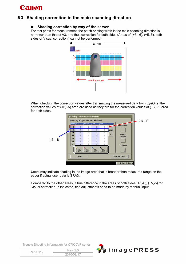
Trouble Shooting Information for C7000VP series
Page 119 Rev. 2.0 2010/09/17
6.3 Shading correction in the main scanning direction Shading correction by way of the server For test prints for measurement, the patch printing width in the main scanning direction is narrower than that of A3, and thus correction for both sides (Areas of (+6, -6), (+5,-5), both sides of ‘visual correction’) cannot be performed.
When checking the correction values after transmitting the measured data from EyeOne, the correction values of (+5, -5) area are used as they are for the correction values of (+6, -6) area for both sides.
Users may indicate shading in the image area that is broader than measured range on the paper if actual user data is SRA3. Compared to the other areas, if hue difference in the areas of both sides (+6,-6), (+5,-5) for ‘visual correction’ is indicated, fine adjustments need to be made by manual input.
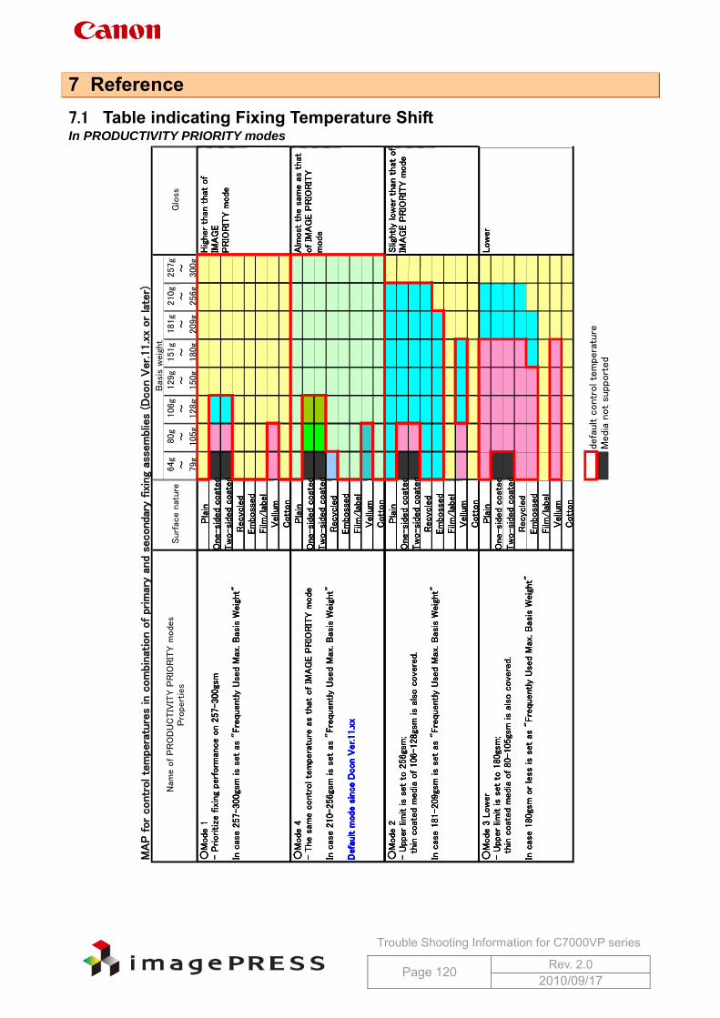
Trouble Shooting Information for C7000VP series
Page 120 Rev. 2.0 2010/09/17
7 Reference 7.1 Table indicating Fixing Temperature Shift In PRODUCTIVITY PRIORITY modes
MA
P for
contr
ol te
mpera
ture
s in
com
bin
atio
n o
f prim
ary
and
second
ary
fixi
ng
asse
mblie
s (D
con V
er.11.x
xor
late
r)
64g
80g
106g
129g
151g
181g
210g
257g
~~
~~
~~
~~
79g
105g
128g
150g
180g
209g
256g
300g
Pla
inO
ne-
side
d coat
ed
Tw
o-si
ded
coat
ed
Recyc
led
Em
boss
ed
Film
/la
bel
Vellu
mC
ott
on
Pla
inO
ne-
side
d coat
ed
Tw
o-si
ded
coat
ed
Recyc
led
Em
boss
ed
Film
/la
bel
Vellu
mC
ott
on
Pla
inO
ne-
side
d coat
ed
Tw
o-si
ded
coat
ed
Recyc
led
Em
boss
ed
Film
/la
bel
Vellu
mC
ott
on
Pla
inO
ne-
side
d coat
ed
Tw
o-si
ded
coat
ed
Recyc
led
Em
boss
ed
Film
/la
bel
Vellu
mC
ott
on
defa
ult c
ontr
ol te
mpera
ture
Medi
a not
supp
ort
ed
○M
ode
1-
Prioritize
fix
ing
perf
orm
ance
on 2
57-3
00gs
m
In c
ase 2
57-300
gsm
is
set
as "
Fre
quent
ly U
sed
Max
. B
asis
Weig
ht"
Hig
her
than
that
of
IMA
GE
PR
IOR
ITY m
ode
Alm
ost
the
sam
e a
s th
atof
IMA
GE P
RIO
RIT
Ym
ode
Nam
e o
f P
RO
DU
CTIV
ITY P
RIO
RIT
Y m
ode
sP
rope
rtie
sSurf
ace
nat
ure
○M
ode
3 L
ow
er
-U
pper
limit is
set
to 1
80gs
m;
th
in c
oat
ed
medi
a of
80-
105
gsm
is
also
cove
red.
In c
ase 1
80gs
m o
r le
ss is
set
as "
Fre
quent
ly U
sed
Max
. B
asis
Weig
ht"
○M
ode
4-
The s
ame c
ontr
ol te
mpe
ratu
re a
s th
at o
f IM
AG
E P
RIO
RIT
Y m
ode
In c
ase 2
10-256
gsm
is
set
as "
Fre
quent
ly U
sed
Max
. B
asis
Weig
ht"
Defa
ult m
ode
sin
ceD
con V
er.11.x
x
Slig
htly
low
er
than
that
of
IMA
GE P
RIO
RIT
Y m
ode
Low
er
○M
ode
2-
Upp
er
limit is
set
to 2
56gs
m;
th
in c
oat
ed
medi
a of
106
-128
gsm
is
also
cove
red.
In c
ase 1
81-209
gsm
is
set
as "
Fre
quent
ly U
sed
Max
. B
asis
Weig
ht"
Bas
is w
eig
ht
Glo
ss
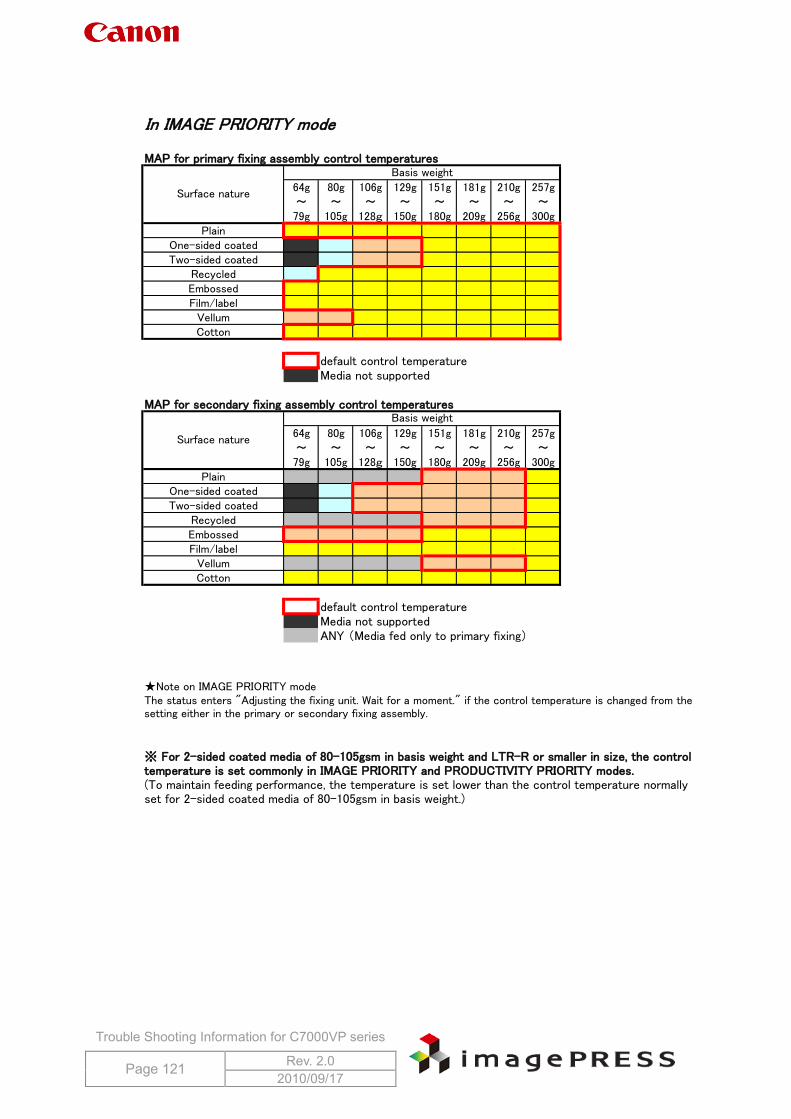
Trouble Shooting Information for C7000VP series
Page 121 Rev. 2.0 2010/09/17
In IMAGE PRIORITY mode
MAP for primary fixing assembly control temperatures
64g 80g 106g 129g 151g 181g 210g 257g~ ~ ~ ~ ~ ~ ~ ~79g 105g 128g 150g 180g 209g 256g 300g
PlainOne-sided coatedTwo-sided coated
RecycledEmbossedFilm/label
VellumCotton
default control temperatureMedia not supported
MAP for secondary fixing assembly control temperatures
64g 80g 106g 129g 151g 181g 210g 257g~ ~ ~ ~ ~ ~ ~ ~79g 105g 128g 150g 180g 209g 256g 300g
PlainOne-sided coatedTwo-sided coated
RecycledEmbossedFilm/label
VellumCotton
default control temperatureMedia not supportedANY (Media fed only to primary fixing)
★Note on IMAGE PRIORITY mode
※ For 2-sided coated media of 80-105gsm in basis weight and LTR-R or smaller in size, the controltemperature is set commonly in IMAGE PRIORITY and PRODUCTIVITY PRIORITY modes.(To maintain feeding performance, the temperature is set lower than the control temperature normallyset for 2-sided coated media of 80-105gsm in basis weight.)
The status enters "Adjusting the fixing unit. Wait for a moment." if the control temperature is changed from thesetting either in the primary or secondary fixing assembly.
Surface nature
Basis weight
Surface nature
Basis weight
Trouble Shooting Information for C7000VP series
Page 122 Rev. 2.0 2010/09/17
7.2 Addition of ‘CP-PRINT’ ‘CP-PRINT’ is newly added in service mode COPIER > Function > MISC-P. (COLOR PROFESSIONAL SERVICE REPORT) CP-PRINT contains the following information:
COLOR PROFESSIONAL SERVICE REPORT SERIAL NO System Name PASCL-TY (PASCAL paper settings): COPIER > OPTION > BODY > PASCL-TY TEMP (Temperature inside machine): COPIER > DISPLAY > ANALOG > TEMP HUM (Humidity inside machine): COPIER > DISPLAY > ANALOG >HUM ABS-HUM (Absolute moisture content): COPIER > DISPLAY >ANALOG >ABS-HUM CNT-TYPE (EFI controller type): COPIER > OPTION > INT-FACE > CNT-TYPE Total Counter (indicated by pressing the counter key) COPY SERVICE REPORT ENVIRONMENT LOG REPORT JAM-ERR HISTORY REPORT
CP-PRINT may contain some information necessary for quality problem inspection. When a problem occurs, please collect CP-PRINT in addition to a failed part, an actual image sample, and the information of the occurrence condition.
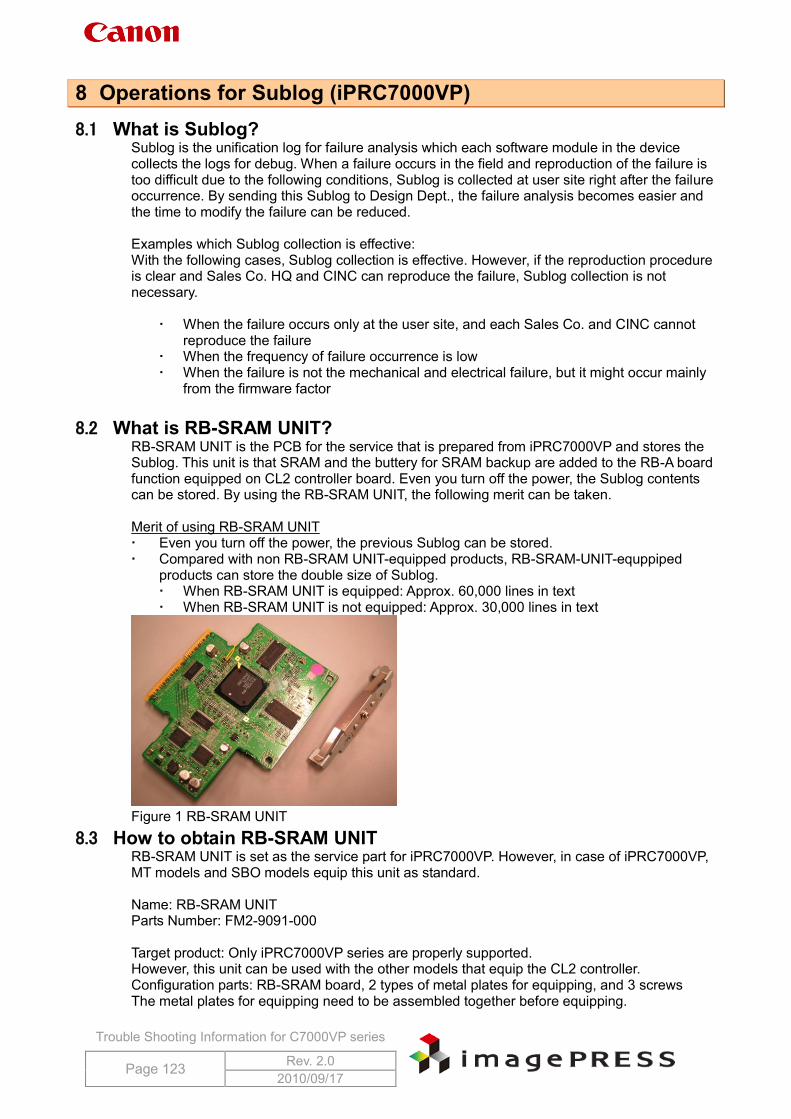
Trouble Shooting Information for C7000VP series
Page 123 Rev. 2.0 2010/09/17
8 Operations for Sublog (iPRC7000VP) 8.1 What is Sublog?
Sublog is the unification log for failure analysis which each software module in the device collects the logs for debug. When a failure occurs in the field and reproduction of the failure is too difficult due to the following conditions, Sublog is collected at user site right after the failure occurrence. By sending this Sublog to Design Dept., the failure analysis becomes easier and the time to modify the failure can be reduced. Examples which Sublog collection is effective: With the following cases, Sublog collection is effective. However, if the reproduction procedure is clear and Sales Co. HQ and CINC can reproduce the failure, Sublog collection is not necessary.
When the failure occurs only at the user site, and each Sales Co. and CINC cannot reproduce the failure
When the frequency of failure occurrence is low When the failure is not the mechanical and electrical failure, but it might occur mainly
from the firmware factor
8.2 What is RB-SRAM UNIT? RB-SRAM UNIT is the PCB for the service that is prepared from iPRC7000VP and stores the Sublog. This unit is that SRAM and the buttery for SRAM backup are added to the RB-A board function equipped on CL2 controller board. Even you turn off the power, the Sublog contents can be stored. By using the RB-SRAM UNIT, the following merit can be taken. Merit of using RB-SRAM UNIT Even you turn off the power, the previous Sublog can be stored. Compared with non RB-SRAM UNIT-equipped products, RB-SRAM-UNIT-equppiped
products can store the double size of Sublog. When RB-SRAM UNIT is equipped: Approx. 60,000 lines in text When RB-SRAM UNIT is not equipped: Approx. 30,000 lines in text
Figure 1 RB-SRAM UNIT
8.3 How to obtain RB-SRAM UNIT RB-SRAM UNIT is set as the service part for iPRC7000VP. However, in case of iPRC7000VP, MT models and SBO models equip this unit as standard. Name: RB-SRAM UNIT Parts Number: FM2-9091-000 Target product: Only iPRC7000VP series are properly supported. However, this unit can be used with the other models that equip the CL2 controller. Configuration parts: RB-SRAM board, 2 types of metal plates for equipping, and 3 screws The metal plates for equipping need to be assembled together before equipping.
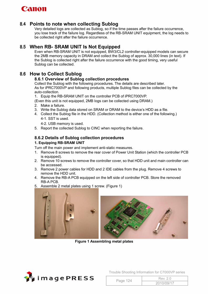
Trouble Shooting Information for C7000VP series
Page 124 Rev. 2.0 2010/09/17
8.4 Points to note when collecting Sublog
Very detailed logs are collected as Sublog, so if the time passes after the failure occurrence, you lose track of the failure log. Regardless of the RB-SRAM UNIT equipment, the log needs to be collected right after the failure occurrence.
8.5 When RB- SRAM UNIT Is Not Equipped Even when RB-SRAM UNIT is not equipped, BW3/CL2 controller-equipped models can secure the 2MB memory capacity in DRAM and collect the Sublog of approx. 30,000 lines (in text). If the Sublog is collected right after the failure occurrence with the good timing, very useful Sublog can be collected.
8.6 How to Collect Sublog 8.6.1 Overview of Sublog collection procedures Collect the Sublog with the following procedures. The details are described later. As for iPRC7000VP and following products, multiple Sublog files can be collected by the auto-collection. 1. Equip the RB-SRAM UNIT on the controller PCB of iPRC7000VP. (Even this unit is not equipped, 2MB logs can be collected using DRAM.) 2. Make a failure. 3. Write the Sublog data stored on SRAM or DRAM to the device’s HDD as a file. 4. Collect the Sublog file in the HDD. (Collection method is either one of the following.)
4-1. SST is used. 4-2. USB memory is used.
5. Report the collected Sublog to CINC when reporting the failure. 8.6.2 Details of Sublog collection procedures 1. Equipping RB-SRAM UNIT Turn off the main power and implement anti-static measures. 1. Remove 8 screws to remove the rear cover of Power Unit Station (which the controller PCB
is equipped). 2. Remove 10 screws to remove the controller cover, so that HDD unit and main controller can
be accessed. 3. Remove 2 power cables for HDD and 2 IDE cables from the plug. Remove 4 screws to
remove the HDD unit. 4. Remove the RB-A PCB equipped on the left side of controller PCB. Store the removed
RB-A PCB. 5. Assemble 2 metal plates using 1 screw. (Figure 1)
Figure 1 Assembling metal plates
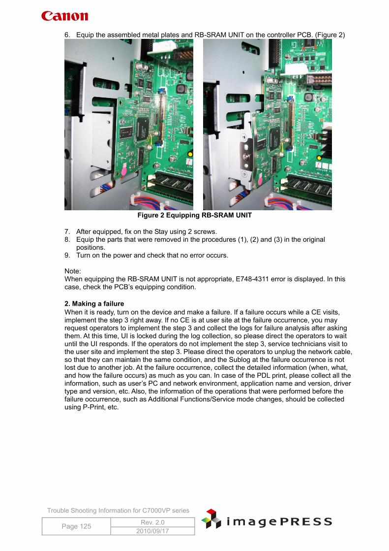
Trouble Shooting Information for C7000VP series
Page 125 Rev. 2.0 2010/09/17
6. Equip the assembled metal plates and RB-SRAM UNIT on the controller PCB. (Figure 2)
Figure 2 Equipping RB-SRAM UNIT
7. After equipped, fix on the Stay using 2 screws. 8. Equip the parts that were removed in the procedures (1), (2) and (3) in the original
positions. 9. Turn on the power and check that no error occurs. Note: When equipping the RB-SRAM UNIT is not appropriate, E748-4311 error is displayed. In this case, check the PCB’s equipping condition. 2. Making a failure When it is ready, turn on the device and make a failure. If a failure occurs while a CE visits, implement the step 3 right away. If no CE is at user site at the failure occurrence, you may request operators to implement the step 3 and collect the logs for failure analysis after asking them. At this time, UI is locked during the log collection, so please direct the operators to wait until the UI responds. If the operators do not implement the step 3, service technicians visit to the user site and implement the step 3. Please direct the operators to unplug the network cable, so that they can maintain the same condition, and the Sublog at the failure occurrence is not lost due to another job. At the failure occurrence, collect the detailed information (when, what, and how the failure occurs) as much as you can. In case of the PDL print, please collect all the information, such as user’s PC and network environment, application name and version, driver type and version, etc. Also, the information of the operations that were performed before the failure occurrence, such as Additional Functions/Service mode changes, should be collected using P-Print, etc.
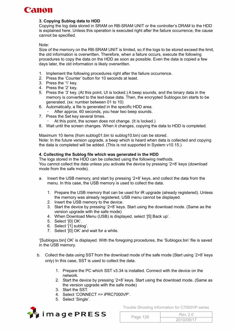
Trouble Shooting Information for C7000VP series
Page 126 Rev. 2.0 2010/09/17
3. Copying Sublog data to HDD Copying the log data stored in SRAM on RB-SRAM UNIT or the controller’s DRAM to the HDD is explained here. Unless this operation is executed right after the failure occurrence, the cause cannot be specified. Note: Size of the memory on the RB-SRAM UNIT is limited, so if the logs to be stored exceed the limit, the old information is overwritten. Therefore, when a failure occurs, execute the following procedures to copy the data on the HDD as soon as possible. Even the data is copied a few days later, the old information is likely overwritten. 1. Implement the following procedures right after the failure occurrence. 2. Press the ‘Counter’ button for 10 seconds at least. 3. Press the ‘1’ key. 4. Press the ‘2’ key. 5. Press the ‘3’ key. (At this point, UI is locked.) A beep sounds, and the binary data in the
memory is converted to the text-base data. Then, the encrypted Sublogxx.bin starts to be generated. (xx: number between 01 to 10)
6. Automatically, a file is generated in the specific HDD area. After approx. 60 seconds, you hear two beep sounds.
7. Press the Set key several times. At this point, the screen does not change. (It is locked.)
8. Wait until the screen changes. When it changes, copying the data to HDD is completed. Maximum 10 items (from sublog01.bin to sublog10.bin) can be stored. Note: In the future version upgrade, a beep which is heard when data is collected and copying the data is completed will be added. (This is not supported in System v10.15.) 4. Collecting the Sublog file which was generated in the HDD The logs stored in the HDD can be collected using the following methods. You cannot collect the data unless you activate the device by pressing ‘2+8’ keys (download mode from the safe mode). a. Insert the USB memory, and start by pressing ‘2+8’ keys, and collect the data from the
menu. In this case, the USB memory is used to collect the data.
1. Prepare the USB memory that can be used for iR upgrade (already registered). Unless the memory was already registered, USB menu cannot be displayed.
2. Insert the USB memory to the device. 3. Start the device by pressing ‘2+8’ keys. Start using the download mode. (Same as the
version upgrade with the safe mode) 4. When Download Menu (USB) is displayed, select ‘[5] Back up’. 5. Select ‘[0] OK’. 6. Select ‘[1] sublog’. 7. Select ‘[0] OK’ and wait for a while.
‘[Sublogxx.bin] OK’ is displayed. With the foregoing procedures, the ‘Sublogxx.bin’ file is saved in the USB memory.
b. Collect the data using SST from the download mode of the safe mode (Start using ‘2+8’ keys
only) In this case, SST is used to collect the data.
1. Prepare the PC which SST v3.34 is installed. Connect with the device on the network.
2. Start the device by pressing ‘2+8’ keys. Start using the download mode. (Same as the version upgrade with the safe mode)
3. Start the SST. 4. Select ‘CONNECT => iPRC7000VP’. 5. Select ‘Single’.
Trouble Shooting Information for C7000VP series
Page 127 Rev. 2.0 2010/09/17
6. Select ‘START’ button. 7. Select ‘Upload Data’ button. 8. Sublog data stored in the list on the right side is displayed. Select SublogXX.bin,
which you want to download and select ‘Start’ button. (XX: automatically generated from 01 to 10.)
9. Select ‘Save’ and ‘OK’ buttons. At this time, you can write in Memo. With the foregoing procedures, the ‘ServData’ folder is automatically generated on the PC drive. In this folder, both ‘Sublogxx.bin.upd’ and ‘Sublogxx.bin.upd.txt’ files are stored. Example: C:¥ServData¥iPC7000V¥xxxxxxxx (device serial number) ¥Sublog01.bin.upd
8.7 Information Required at Log Collection Is it too difficult to analyze only using the Sublog, so the following information needs to be provided with the Sublog.
P-Print in Service mode (information of firmware version, various settings values, etc.) Details of operation procedures (step by step) until the failure occurs
8.8 Points to Note
Points to note when operating in the field are described below. 8.8.1. Encryption of files Sublog information includes various information necessary for analysis, so the files are encrypted. For this reason, any persons other than Design Dept. cannot read the contents. Please explain this condition to the users and inform that their log information is not disclosed to anybody except the responsible departments. 8.8.2. Setting methods to collect Sublog automatically If you set the following service mode setting from Service mode (Level2), Sublog can be automatically stored at various events occurrence. During this auto-collection, the screen is locked, so please explain the users about this condition beforehand. If the device is turned off while the screen is locked, the Sublog file might not be generated. This setting is enabled in the following cases.
When an error code occurs When the device reboots sometimes When CPU Exception occurs
Devices prior to iPRC7000VP save the Sublog in /BOOTDEV, so depending on the timing, the device is not started sometimes. iPRC7000VP does not have such a symptom. Service mode (Level2) -> COPIER/FUNCTION/SYSTEM/DEBUG-1
0: PLOG is saved when Reboot/Exception is detected. 1: PLOG is saved when Reboot/Exception/Ecode is detected. 2: SUBLOG is saved when Reboot/Exception/Ecode is detected. 3: SUBLOG is saved using the overwriting mode when Reboot/Exception/Ecode is detected.
For the operations of foregoing setting ‘3’, refer to 9-2. In case of the foregoing setting ‘2’, 10 files can be generated, but the further files (more than 10 files) cannot be saved. Exception: Unexpected error occurrence. Exceptional error. PLOG: Compared with Sublog, only the limited information can be collected, so set to save the Sublog usually.
Trouble Shooting Information for C7000VP series
Page 128 Rev. 2.0 2010/09/17
8.9 Reference Information 8.9.1. Data size of Sublog Sublog file size can be larger than the SRAM size on RB-SRAM UNIT or the size secured on DRAM. The reason for this is that binary data on SRAM and DRAM is converted to the text data once and then encrypted.
When RB-SRAM UNIT is equipped: Approx. 10MB When RB-SRAM UNIT is not equipped: Approx. 5MB
8.9.2.Specifications regarding multiple Sublog files creation at auto-collection setting (Will be supported from iPRC7000VP and the following products) When setting the auto-collection and overwriting mode, if 10 files are stored, the latest file is overwritten (to keep the old log which was automatically collected at the failure occurrence). First of all, /APL_LOG/SUBLOG.txt is created by overwriting. Then, an empty space is searched in the order from SUBLOG01 to 10.txt and the data is copied. With this specification, SUBLOG.txt is always recorded the latest log. When referring from 01 to 10, the time stamp of the file system is referred for judging (new or old). When all between 01 and 10 are used, the latest file is overwritten. When excerpting, all files are encrypted as SUBLOG01 to 10.bin. 01 to 10: Automatically generated logs at auto-collection setting. Logs without numbers are the latest logs that are internally used in Design and Evaluation Departments. (These logs are internally operated, so they cannot be collected using SST and USB memory.) 8.9.3. Timing to delete the Sublog from HDD When collecting the Sublog using SST and USB memory, the files in the device are automatically deleted. 8.9.4. When RB-SRAM UNIT is powered off Logs are disappeared after turning off and on the main power. They remain stored while the power is on. They also remain stored after the software reboot.
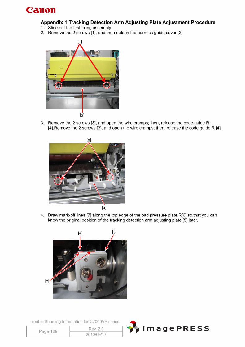
Trouble Shooting Information for C7000VP series
Page 129 Rev. 2.0 2010/09/17
Appendix 1 Tracking Detection Arm Adjusting Plate Adjustment Procedure 1. Slide out the first fixing assembly. 2. Remove the 2 screws [1], and then detach the harness guide cover [2].
3. Remove the 2 screws [3], and open the wire cramps; then, release the code guide R [4].Remove the 2 screws [3], and open the wire cramps; then, release the code guide R [4].
4. Draw mark-off lines [7] along the top edge of the pad pressure plate R[6] so that you can know the original position of the tracking detection arm adjusting plate [5] later.
[1]
[2]
[3]
[4]
[5] [6]
[7]
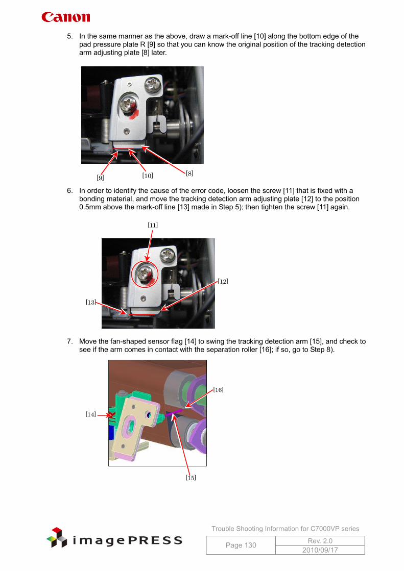
Trouble Shooting Information for C7000VP series
Page 130 Rev. 2.0 2010/09/17
5. In the same manner as the above, draw a mark-off line [10] along the bottom edge of the pad pressure plate R [9] so that you can know the original position of the tracking detection arm adjusting plate [8] later.
6. In order to identify the cause of the error code, loosen the screw [11] that is fixed with a bonding material, and move the tracking detection arm adjusting plate [12] to the position 0.5mm above the mark-off line [13] made in Step 5); then tighten the screw [11] again.
7. Move the fan-shaped sensor flag [14] to swing the tracking detection arm [15], and check to
see if the arm comes in contact with the separation roller [16]; if so, go to Step 8).
[8] [9] [10]
[11]
[12]
[13]
[14]
[15]
[16]
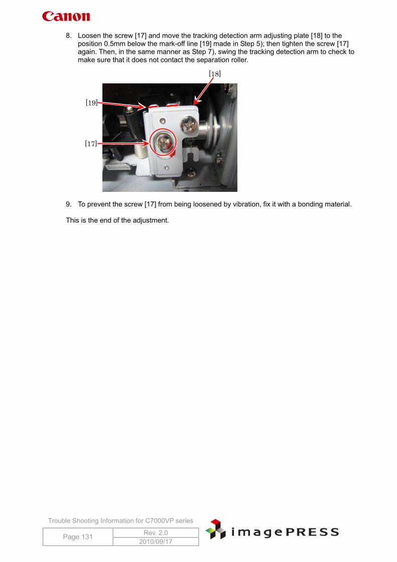
Trouble Shooting Information for C7000VP series
Page 131 Rev. 2.0 2010/09/17
8. Loosen the screw [17] and move the tracking detection arm adjusting plate [18] to the position 0.5mm below the mark-off line [19] made in Step 5); then tighten the screw [17] again. Then, in the same manner as Step 7), swing the tracking detection arm to check to make sure that it does not contact the separation roller.
9. To prevent the screw [17] from being loosened by vibration, fix it with a bonding material. This is the end of the adjustment.
[17]
[19]
[18]
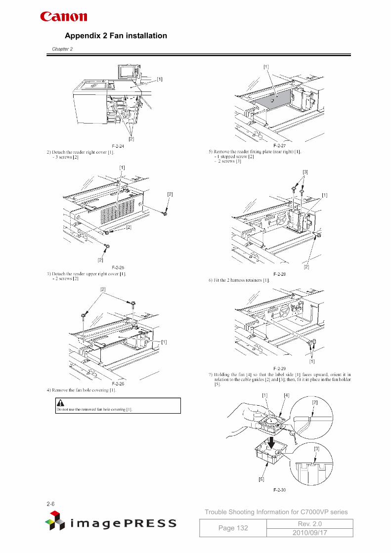
Trouble Shooting Information for C7000VP series
Page 132 Rev. 2.0 2010/09/17
Appendix 2 Fan installation
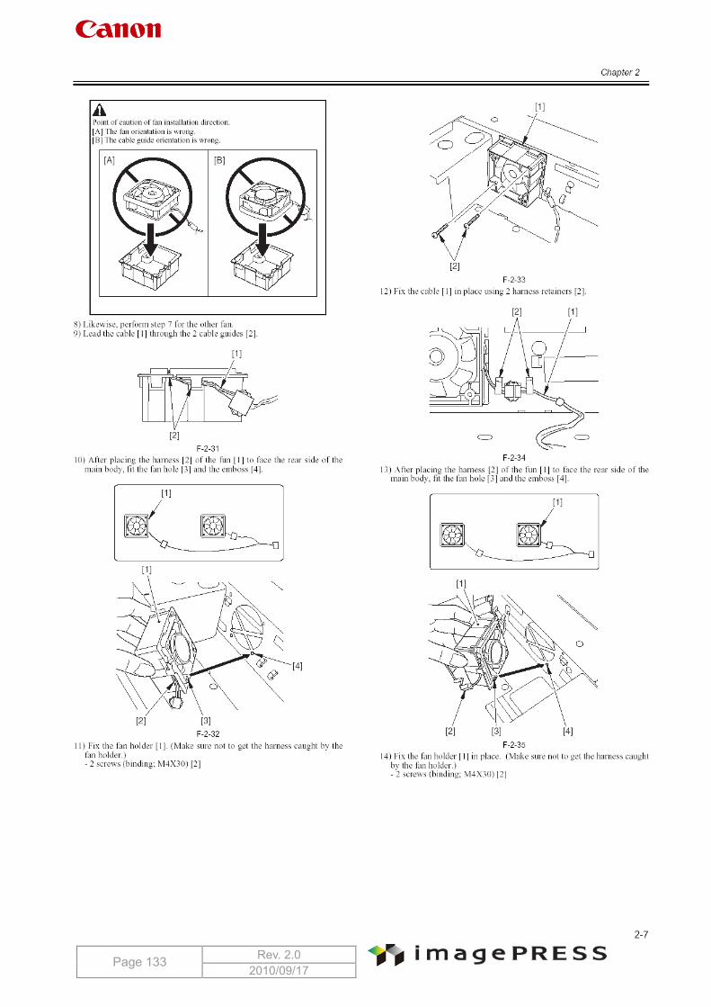
Trouble Shooting Information for C7000VP series
Page 133 Rev. 2.0 2010/09/17
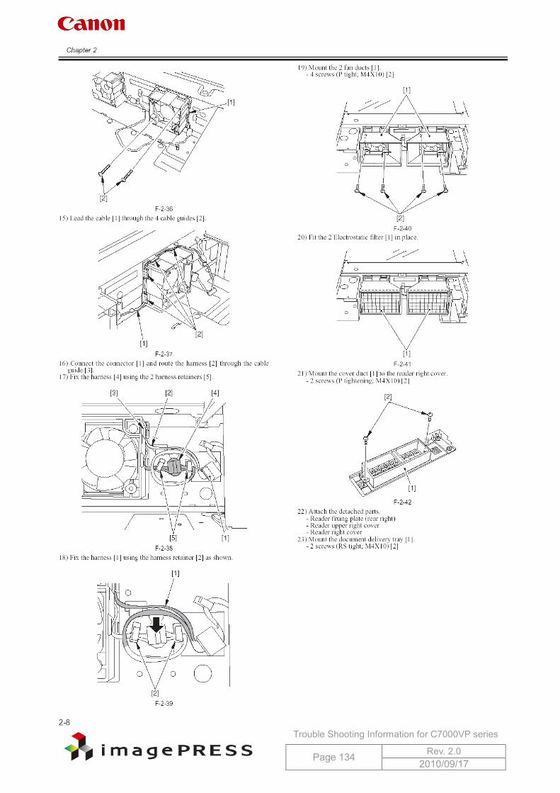
Trouble Shooting Information for C7000VP series
Page 134 Rev. 2.0 2010/09/17
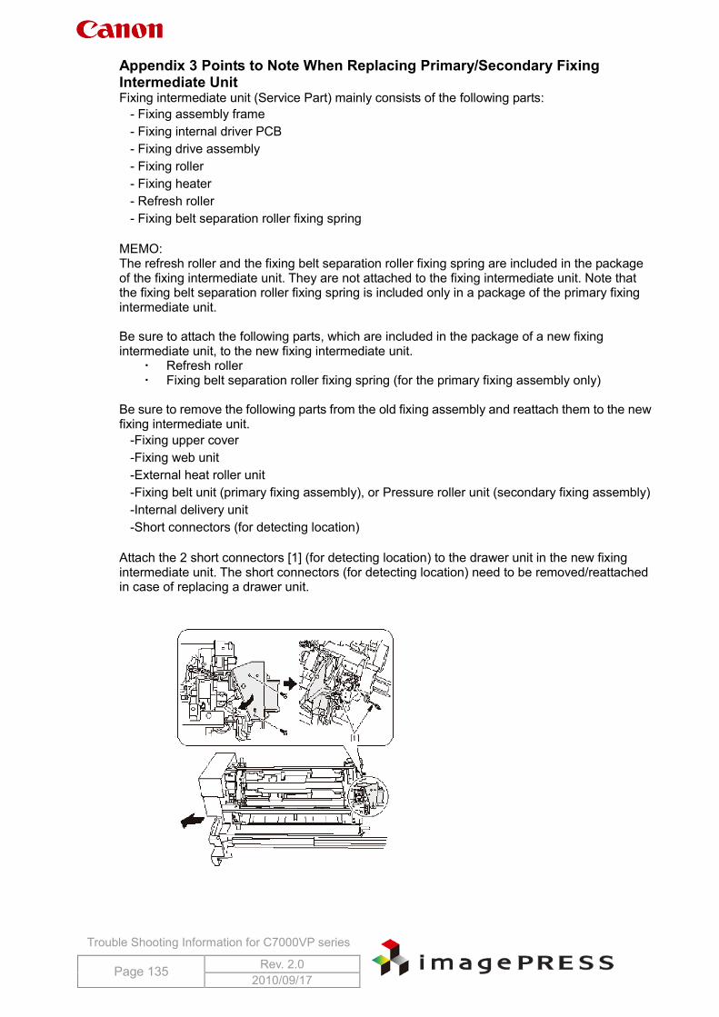
Trouble Shooting Information for C7000VP series
Page 135 Rev. 2.0 2010/09/17
Appendix 3 Points to Note When Replacing Primary/Secondary Fixing Intermediate Unit Fixing intermediate unit (Service Part) mainly consists of the following parts:
- Fixing assembly frame - Fixing internal driver PCB - Fixing drive assembly - Fixing roller - Fixing heater - Refresh roller - Fixing belt separation roller fixing spring
MEMO: The refresh roller and the fixing belt separation roller fixing spring are included in the package of the fixing intermediate unit. They are not attached to the fixing intermediate unit. Note that the fixing belt separation roller fixing spring is included only in a package of the primary fixing intermediate unit. Be sure to attach the following parts, which are included in the package of a new fixing intermediate unit, to the new fixing intermediate unit.
Refresh roller Fixing belt separation roller fixing spring (for the primary fixing assembly only)
Be sure to remove the following parts from the old fixing assembly and reattach them to the new fixing intermediate unit.
-Fixing upper cover -Fixing web unit -External heat roller unit -Fixing belt unit (primary fixing assembly), or Pressure roller unit (secondary fixing assembly) -Internal delivery unit -Short connectors (for detecting location)
Attach the 2 short connectors [1] (for detecting location) to the drawer unit in the new fixing intermediate unit. The short connectors (for detecting location) need to be removed/reattached in case of replacing a drawer unit.
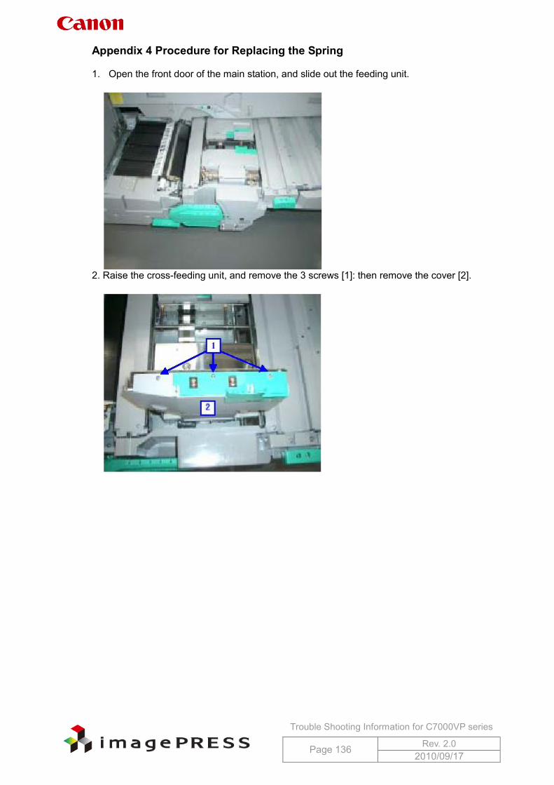
Trouble Shooting Information for C7000VP series
Page 136 Rev. 2.0 2010/09/17
Appendix 4 Procedure for Replacing the Spring 1. Open the front door of the main station, and slide out the feeding unit.
2. Raise the cross-feeding unit, and remove the 3 screws [1]: then remove the cover [2].
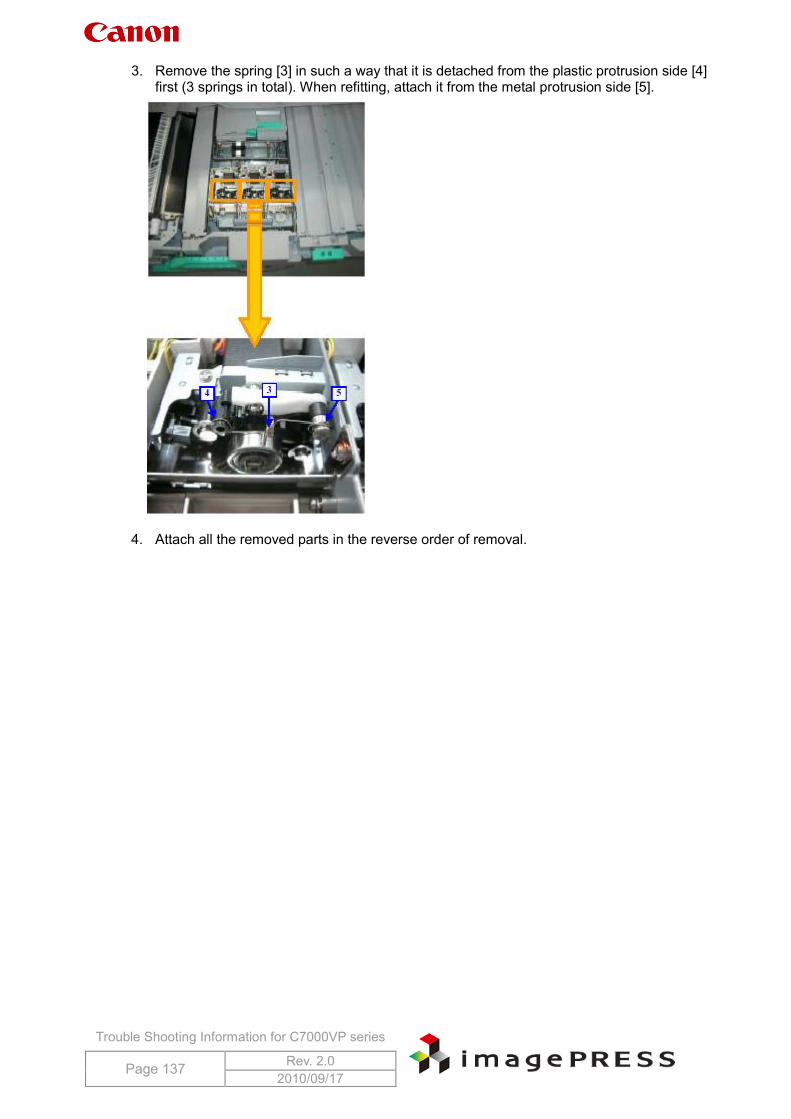
Trouble Shooting Information for C7000VP series
Page 137 Rev. 2.0 2010/09/17
3. Remove the spring [3] in such a way that it is detached from the plastic protrusion side [4] first (3 springs in total). When refitting, attach it from the metal protrusion side [5].
4. Attach all the removed parts in the reverse order of removal.