Embed Size (px)
Citation preview
Tiina Ojamo
FATIGUE OF THE ORTHOTROPIC LAYER
in Glass Fiber Reinforced Composites
Bachelor’s thesis Degree Programme of Materials and Surface Treatment
May 2012
KUVAILULEHTI
Opinnäytetyön päivämäärä
7.5.2012
Tekijä
Tiina Ojamo
Koulutusohjelma ja suuntautuminen
Materiaali- ja pintakäsittelytekniikka
Nimeke Ortotrooppisen kerroksen väsyminen lasikuitulujitetuissa komposiiteissa Tiivistelmä Opinnäytetyö käsitteli lasikuitulujitettuja komposiitteja ja niiden mekaanisten ominaisuuksien määrittä-mistä. Lasikuitulaminaattien valmistus kuvattiin ja staattisten sekä dynaamisten kokeiden periaatteet selvitettiin. Kahta laminaattityyppiä edustavat testikoekappaleet valmistettiin Ahlström Glassfibren Mikkelin teh-taalla. Toinen testattava laminaatti oli lujitettu perinteistä E-lasia käyttäen, toisessa oli käytetty korkean lujuuden omaavaa lasikuitua. Matriisimuovina oli epoksihartsi. Laminaatin valmistajaa kiinnosti selvitys siitä, onko korkean lujuuden omaavaa kuitua sisältävällä laminaatilla selvästi paremmat ominaisuudet kuin vertailumateriaalilla. Tuulimyllyn siiven laparakenteessa käytettävältä komposiitilta vaaditaan eri-tyisesti hyviä lujuus- ja jäykkyysominaisuuksia. Tutkimusongelmaan sisältyi myös kysymys, voiko staat-tisten kokeiden perusteella ennakoida väsytyskokeiden tuloksia. Staattisten vetokokeiden tuloksista ilmeni, että korkean lujuuden lasikuitua sisältävä materiaali oli jäyk-kyydeltään parempi. Kimmomoduulin lukuarvot olivat noin kymmenen prosenttia korkeammat kuin vertailukoekappaleilla. Väsymiskäyttäytymisen ennustamista staattisten kokeiden tulosten perusteella pohdittiin kirjallisuuden ja aiempien tutkimushavaintojen valossa.
Asiasanat (avainsanat)
laminaatti, lasikuitumuovi, lujuus, väsyminen Sivumäärä Kieli URN
46 + 4 (Liite 1)
englanti
Huomautus (huomautukset liitteistä) Liitteessä luottamuksellista tietoa. Ohjaavan opettajan nimi
Tapio Lepistö
Opinnäytetyön toimeksiantaja
Ahlstrom Glassfibre Oy, Mikkeli
DESCRIPTION
Date of the bachelor’s thesis
7.5.2012
Author
Tiina Ojamo
Degree programme and option
Degree Programme of Materials and Surface Treat-ment
Name of the bachelor’s thesis
Fatigue of the Orthotropic Layer in Glass Fiber Reinforced Composites Abstract
This thesis focused on the characterization of glass fiber reinforced composite materials and the determi-nation of their mechanical properties. The manufacture of glass fiber reinforced laminate materials was described and the basic methods of their static and fatigue testing were presented. Two types of glass fiber reinforced laminate specimens were fabricated by Ahlstrom Glassfibre in Mikkeli and applied in the static tests reported in this thesis. One of the specimen types represented traditional E-glass reinforced laminate, the other was cut from laminate material that had been prepared using high strength glass fiber. The manufacturer of the laminate was interested in finding out whether the high strength glass would yield remarkably better test results and thus be worth considering an appropriate material to be used in wind turbine blade structures. Another, mainly theoretical topic in the context of this thesis, was touched on, namely the question, if the results obtained from the static tests could predict the fatigue behavior of composite material. The results of the static tests were reported concentrating mainly on the values of the elastic modulus obtained. This preliminary testing indicated that specimens containing high strength glass fiber had bet-ter stiffness properties. The improvement in the values of the elastic modulus was approximately ten per cent. The potential fatigue behavior of the specimens tested and the various parameters involved in the fatigue behavior of composites were discussed. Subject headings, (keywords)
fatigue, glass fiber composite, strength, elastic modulus, orthotropic Pages Language URN
46 + 4 (Appendix 1)
English
Remarks, notes on appendices
Appendix 1 (p. 1-4) confidential data Tutor
Tapio Lepistö
Bachelor’s thesis assigned by
Ahlstrom Glassfibre Oy, Mikkeli
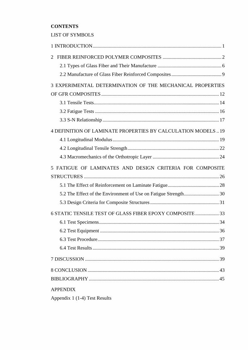
CONTENTS
LIST OF SYMBOLS
1 INTRODUCTION ....................................................................................................... 1
2 FIBER REINFORCED POLYMER COMPOSITES ............................................... 2
2.1 Types of Glass Fiber and Their Manufacture ................................................... 6
2.2 Manufacture of Glass Fiber Reinforced Composites ........................................ 9
3 EXPERIMENTAL DETERMINATION OF THE MECHANICAL PROPERTIES
OF GFR COMPOSITES .............................................................................................. 12
3.1 Tensile Tests .................................................................................................... 14
3.2 Fatigue Tests ................................................................................................... 16
3.3 S-N Relationship ............................................................................................. 17
4 DEFINITION OF LAMINATE PROPERTIES BY CALCULATION MODELS .. 19
4.1 Longitudinal Modulus ..................................................................................... 19
4.2 Longitudinal Tensile Strength ......................................................................... 22
4.3 Macromechanics of the Orthotropic Layer ..................................................... 24
5 FATIGUE OF LAMINATES AND DESIGN CRITERIA FOR COMPOSITE
STRUCTURES ............................................................................................................ 26
5.1 The Effect of Reinforcement on Laminate Fatigue ......................................... 28
5.2 The Effect of the Environment of Use on Fatigue Strength ............................ 30
5.3 Design Criteria for Composite Structures ....................................................... 31
6 STATIC TENSILE TEST OF GLASS FIBER EPOXY COMPOSITE ................... 33
6.1 Test Specimens ................................................................................................ 34
6.2 Test Equipment ............................................................................................... 36
6.3 Test Procedure ................................................................................................. 37
6.4 Test Results ..................................................................................................... 39
7 DISCUSSION ........................................................................................................... 39
8 CONCLUSION ......................................................................................................... 43
BIBLIOGRAPHY ........................................................................................................ 45
APPENDIX
Appendix 1 (1-4) Test Results
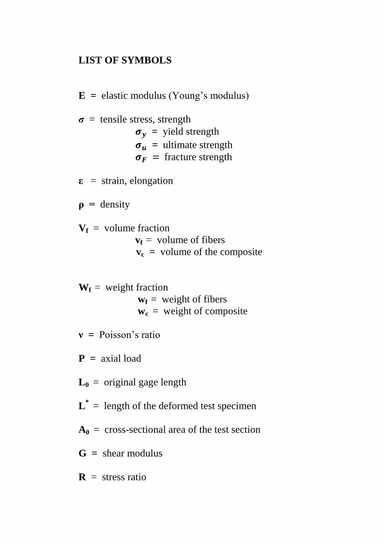
LIST OF SYMBOLS
E = elastic modulus (Young’s modulus)
σ = tensile stress, strength
= yield strength
= ultimate strength
fracture strength
ε = strain, elongation
ρ = density
Vf = volume fraction
vf = volume of fibers
vc = volume of the composite
Wf = weight fraction
wf = weight of fibers
wc = weight of composite
ν = Poisson’s ratio
P = axial load
L0 = original gage length
L* = length of the deformed test specimen
A0 = cross-sectional area of the test section
G = shear modulus
R = stress ratio

1
1 INTRODUCTION
The present study deals with glass fiber reinforced (GFR) composites and their me-
chanical properties. Composites typically consist of two or more materials which to-
gether form a new material that has improved characteristics. A composite material
consists of two main components: a matrix and reinforcement. In glass fiber rein-
forced composites the matrix is often constituted by polymers, and glass fiber func-
tions as a reinforcement. The keen interest in composite materials is for the most part
due to the demands presented by advanced technology. There are various fields that
utilize applications of composites e. g. transportation, building and construction indus-
try, electronics industry as well as sports and leisure. Manufacturers strive to develop
new high performance materials. The specific stiffness, strength and fracture tough-
ness of composites are properties that most interest the composite manufacturing
technologies. /1, p. 7-8. /
This bachelor’s thesis has two major purposes. First, it aims to provide a description
of different types of GFR composites, their manufacture and essential mechanical
properties. The basic forms of static and fatigue testing applied in the determination of
these properties are introduced. The basic properties of laminates are defined and the
analysis of the fiber/matrix relationship in composite structures is discussed from both
the micromechanical and macromechanical points of view. The second aim is to carry
out static tensile tests for two types of unidirectional glass fiber laminate, describe the
test procedure and report the test results. Based on the theoretical background present-
ed, the interpretation and significance of the results are also considered.
There are also two main questions to which the present study wishes to find answers.
The first was put forward by Ahlström Glassfibre in Mikkeli, which was the manufac-
turer of the laminates to be tested. The 84 specimens applied in the tests were cut from
two different types of laminate: the RA and RY specimens were prepared from a lam-
inate with traditional E-glass reinforcement, whereas the WA and WY specimens
were cut from a laminate that contained high strength glass. The manufacturer was
interested in finding out the differences between the test results of the two specimen
types. Would it be worthwhile and cost competitive to use the more expensive high
strength material in laminate structures? Would the evidently improved strength and
stiffness achieved be significant enough? This thesis will focus on the values of the
2
elastic modulus, that is on the stiffness property of the materials. These particular
composite laminates prepared by Ahlström Glassfibre were fabricated in order to be
used in wind turbine blade structures. The demands for the strength and stiffness
properties of the laminate material are understandably high, since blades have to be
designed to function under severe loading and high numbers of fatigue cycling. The
second interesting question is of a more theoretical kind. Can the values of the elastic
modulus obtained in static testing predict the fatigue behavior of GFR composite ma-
terials? Since there are no fatigue test results that could be compared with the data of
this study, the problem has to be approached on the basis of literature.
Chapters 2-4 of this thesis concentrate on the description of GFR composites and their
manufacture. The principles of the experimental determination of their mechanical
properties are presented. In addition, examples of the definition of laminate properties
by calculation models are introduced. Chapter 5 provides a discussion on the fatigue
of laminates. The implications of the fatigue behavior on the design of laminate struc-
tures are also touched on. Chapter 6 consists of the report of the static tests that were
carried out in the material laboratory of Mikkeli University of Applied Sciences. The
results of the tests are presented in Appendix 1, and their interpretation is included in
Chapter 7.
2 FIBER REINFORCED POLYMER COMPOSITES
The term composite refers to a combination of at least two distinct materials in which
the materials in question function together and complement each other. The compo-
nent materials do not, however, blend and form a mixture. Instead, their properties
work together and create a heterogeneous material, whose performance outstands that
of either of the constituent materials. A composite typically consists of two principal
components: a matrix and a reinforcing filler, which is usually in the form of fibers or
particles. The matrix supports the fibers. Reinforced polymers constitute one of the
most important subdivisions among composite materials. The matrix may consist of
either thermosetting resins or thermoplastic polymers. The reinforcing filler, in most
cases fiber, increases significantly the original stiffness and strength of plastics. It is
typical that the mechanical strength of the matrix is relatively low when compared to
the reinforcement. The reinforcement, on the other hand, is often stiffer and brittle. If
the combination of matrix material and reinforcement is supposed to function properly
3
and maximum benefit is to be gained, as much as possible of the applied stress should
be borne by the fibers. The matrix ideally supports the fibers and transmits the exter-
nal loading to them. /1, p. 80; 2 p. 8. /
It is structurally the best alternative to apply reinforcements in a filamentous form to
improve such important properties as strength and stiffness of a plastics composite. A
fiber may contain several thousand filaments whose diameter is only a few microns.
Fiber length may vary from circa 3mm to hundreds of meters in filament winding ap-
plications. A group of filaments is called a strand. Twisted strands form a yarn. Fila-
ment bundles which are held together by a binder are mats. A bundle of continuous
strands is called a roving. /3, p.17-20; 2, p. 14. /
In a typical polymer composite product the reinforcing fibers, strands, or mats are
stacked on top of each other forming layers, which are also called lamina or plies. The
structure that is formed is called a laminate. The simplest type of laminate as regards
to its fiber direction is the unidirectional laminate with all its fibers oriented at 0˚. In
the case of a cross-ply laminate the fibers of every layer are oriented at either 0˚or 90˚
/3, p.22; 4, p.300. /
There are several ways in which composites can be classified. One of them is to di-
vide different composites into groups according to the type of reinforcement applied.
Some composites contain continuous long fibers with unidirectional, bidirectional or
random fiber orientation. Others possess discontinuous fibers, which have random or
some preferential orientation. There are also composites which are reinforced by par-
ticles or whiskers. Another way of classification is based on laminate configuration.
The composite material may be unidirectional and include layers having the same ma-
terial and orientation or it can be a laminate possessing some layers that vary in this
respect. Some of the layers may have different orientation and they can also consist of
a different material. /5, p.2; 3, p. 22. /
In the mechanical models of composite structures it is usually assumed that the mate-
rial is macroscopically homogeneous and linearly elastic. Homogeneous here refers to
the properties of the fiber reinforced layer which are expected to be the same in each
point of the plane. Linearly elastic implies the fact that the deformation in the material
increases proportional to the loading and disappears when the loading is removed. The
4
assumption of the material’s linearly elastic character may be presented when the
loading is low enough and short-term. /3, p.26. / The basic tensile stiffness properties
of metals are obtained by applying only a few tests. Composites tend to be more com-
plicated. This is due to a directional dependence caused by their anisotropy. The ani-
sotropic character of a material depends on how symmetrical it is. Isotropic materials
have countless symmetry planes. Most composites that are used nowadays are two-
dimensional. As a result of this they have one plane of symmetry. They are referred to
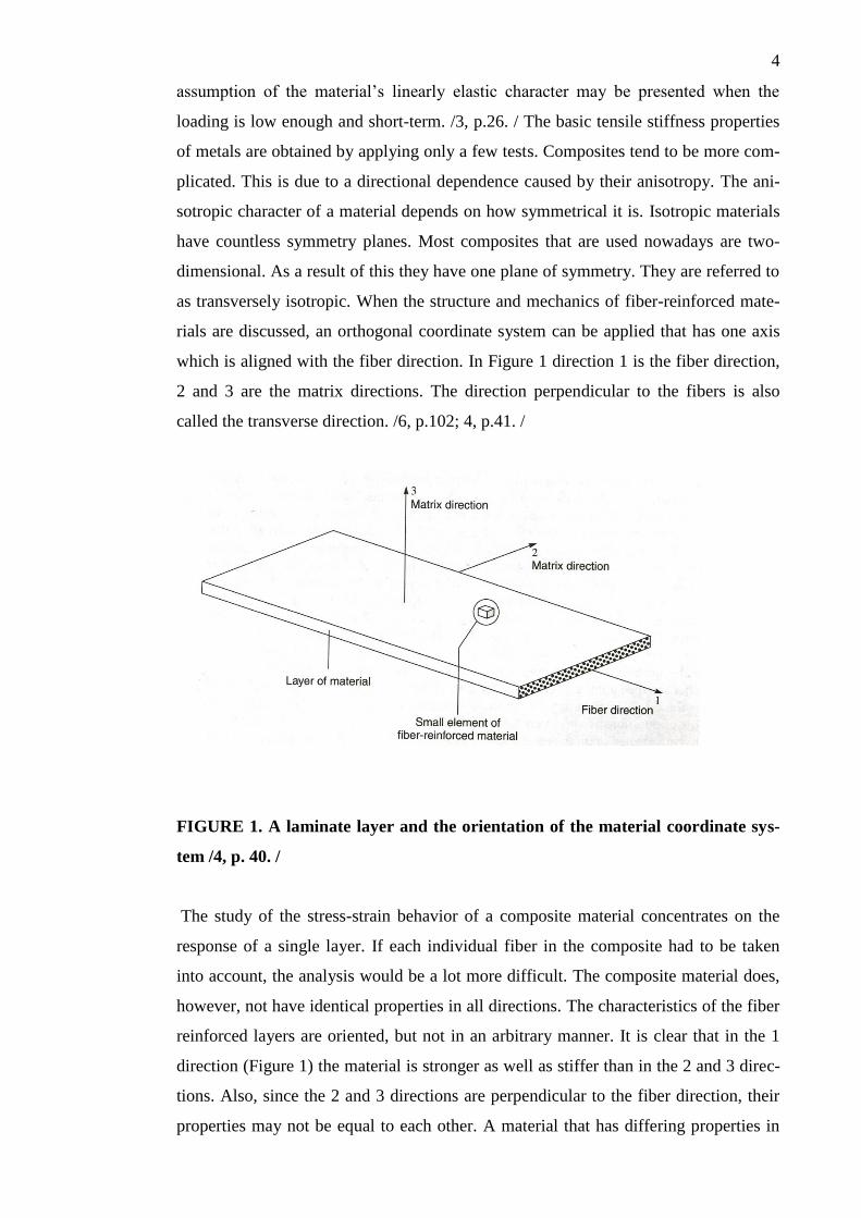
as transversely isotropic. When the structure and mechanics of fiber-reinforced mate-
rials are discussed, an orthogonal coordinate system can be applied that has one axis
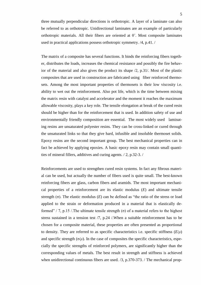
which is aligned with the fiber direction. In Figure 1 direction 1 is the fiber direction,
2 and 3 are the matrix directions. The direction perpendicular to the fibers is also
called the transverse direction. /6, p.102; 4, p.41. /
FIGURE 1. A laminate layer and the orientation of the material coordinate sys-
tem /4, p. 40. /
The study of the stress-strain behavior of a composite material concentrates on the
response of a single layer. If each individual fiber in the composite had to be taken
into account, the analysis would be a lot more difficult. The composite material does,
however, not have identical properties in all directions. The characteristics of the fiber
reinforced layers are oriented, but not in an arbitrary manner. It is clear that in the 1
direction (Figure 1) the material is stronger as well as stiffer than in the 2 and 3 direc-
tions. Also, since the 2 and 3 directions are perpendicular to the fiber direction, their
properties may not be equal to each other. A material that has differing properties in
5
three mutually perpendicular directions is orthotropic. A layer of a laminate can also
be referred to as orthotropic. Unidirectional laminates are an example of particularly
orthotropic materials. All their fibers are oriented at 0˚. Most composite laminates
used in practical applications possess orthotropic symmetry. /4, p.41. /
The matrix of a composite has several functions. It binds the reinforcing fibers togeth-
er, distributes the loads, increases the chemical resistance and possibly the fire behav-
ior of the material and also gives the product its shape /2, p.31/. Most of the plastic
composites that are used in construction are fabricated using fiber reinforced thermo-
sets. Among the most important properties of thermosets is their low viscosity i.e.
ability to wet out the reinforcement. Also pot life, which is the time between mixing
the matrix resin with catalyst and accelerator and the moment it reaches the maximum
allowable viscosity, plays a key role. The tensile elongation at break of the cured resin
should be higher than for the reinforcement that is used. In addition safety of use and
environmentally friendly composition are essential. The most widely used laminat-
ing resins are unsaturated polyester resins. They can be cross-linked or cured through
the unsaturated links so that they give hard, infusible and insoluble thermoset solids.
Epoxy resins are the second important group. The best mechanical properties can in
fact be achieved by applying epoxies. A basic epoxy resin may contain small quanti-
ties of mineral fillers, additives and curing agents. / 2, p.32-3. /
Reinforcements are used to strengthen cured resin systems. In fact any fibrous materi-
al can be used, but actually the number of fibers used is quite small. The best-known
reinforcing fibers are glass, carbon fibers and aramids. The most important mechani-
cal properties of a reinforcement are its elastic modulus (E) and ultimate tensile
strength (σ). The elastic modulus (E) can be defined as “the ratio of the stress or load
applied to the strain or deformation produced in a material that is elastically de-
formed” / 7, p.15 /.The ultimate tensile strength (σ) of a material refers to the highest
stress sustained in a tension test /7, p.24 /.When a suitable reinforcement has to be
chosen for a composite material, these properties are often presented as proportional
to density. They are referred to as specific characteristics i.e. specific stiffness (E/ρ)
and specific strength (σ/ρ). In the case of composites the specific characteristics, espe-
cially the specific strengths of reinforced polymers, are significantly higher than the
corresponding values of metals. The best result in strength and stiffness is achieved
when unidirectional continuous fibers are used. /3, p.370-373. / The mechanical prop-
6
erties of the end product are also to a great extent affected by the bonding between
reinforcement and matrix. It is usual to prefer a strong bond between matrix and rein-
forcement. It is, however, possible that in some cases the toughness of a material,
which actually means its ability to absorb energy, is increased by a weak bond be-
tween matrix and fiber. On such occasions energy is absorbed due to slipping between
matrix and fiber. / 6, p. 70-71. /
The most important reinforcement both commercially and for industrial applications is
glass fiber. Continuous filament glass fibers started to be applied as reinforcement in
the 1950s, even though they were produced commercially in the UK as early as in
about 1930. Glass in the form of fibers is relatively inexpensive. This undoubtedly
accounts for the fact that glass covers more than 95% of all use of reinforcements. It
has been estimated that globally its application to reinforce plastics will increase 3-5%
each year. In Finland glass fiber was until 2011 manufactured by Ahlstrom Glassfibre
in Karhula. Ahlstrom manufacturing plant in Mikkeli produces, for example, various
glass fiber composite products, glass fiber tissue and industrial nonwovens. /3, p. 74. /
The test specimens of the experimental part of this study were manufactured at Ahl-
strom Glassfibre Mikkeli plant. The static tests which will be reported in this thesis
form part of a larger project, in which high quality glass fiber laminates with signifi-
cantly better fatigue properties are tested in order to be used in wind turbine blade
production.
2.1 Types of Glass Fiber and Their Manufacture
There are a number of different types of glass which can be converted into fibers that
can function as reinforcement. Commercially only a few basic compositions are worth
using. ‘A’ or Alkali glass used to be commonly applied as the basic material in glass
fiber production. Nowadays ‘E’ or Electrical grade glass is used in most applications.
E-glass is a low alkali content borosilicate glass. It has good electrical and mechanical
properties as well as significant chemical resistance. Also C-glass is an especially
chemical resistant glass. It is used in the manufacture of surfacing tissues to bring ad-
ditional chemical resistance e.g. in corrosive environments. There is also a variety, the
ECR-glass developed by Owens Corning Fiberglass, in which the good mechanical
qualities of E-glass and the chemical resistance of C-glass combine. In addition, ‘R’
and ‘S’ glasses are produced as fibers to provide advanced composites with extra
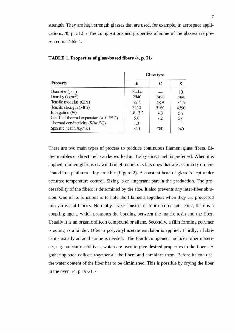
7
strength. They are high strength glasses that are used, for example, in aerospace appli-
cations. /8, p. 312. / The compositions and properties of some of the glasses are pre-
sented in Table 1.
TABLE 1. Properties of glass-based fibers /4, p. 21/
There are two main types of process to produce continuous filament glass fibers. Ei-
ther marbles or direct melt can be worked at. Today direct melt is preferred. When it is
applied, molten glass is drawn through numerous bushings that are accurately dimen-
sioned in a platinum alloy crucible (Figure 2). A constant head of glass is kept under
accurate temperature control. Sizing is an important part in the production. The pro-
cessability of the fibers is determined by the size. It also prevents any inter-fiber abra-
sion. One of its functions is to hold the filaments together, when they are processed
into yarns and fabrics. Normally a size consists of four components. First, there is a
coupling agent, which promotes the bonding between the matrix resin and the fiber.
Usually it is an organic silicon compound or silane. Secondly, a film forming polymer
is acting as a binder. Often a polyvinyl acetate emulsion is applied. Thirdly, a lubri-
cant - usually an acid amine is needed. The fourth component includes other materi-
als, e.g. antistatic additives, which are used to give desired properties to the fibers. A
gathering shoe collects together all the fibers and combines them. Before its end use,
the water content of the fiber has to be diminished. This is possible by drying the fiber
in the oven. /4, p.19-21. /
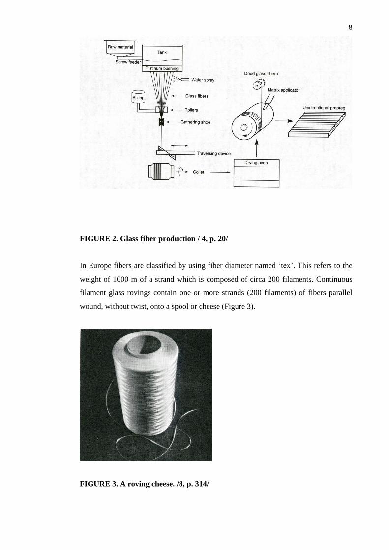
8
FIGURE 2. Glass fiber production / 4, p. 20/
In Europe fibers are classified by using fiber diameter named ‘tex’. This refers to the
weight of 1000 m of a strand which is composed of circa 200 filaments. Continuous
filament glass rovings contain one or more strands (200 filaments) of fibers parallel
wound, without twist, onto a spool or cheese (Figure 3).
FIGURE 3. A roving cheese. /8, p. 314/
9
The size of the spool and number of strands are dependent on end use. Different types
of roving are manufactured for different processes. /8, p. 313-314. / When advanced
composites are developed and produced, various parameters have to be taken into ac-
count. The glass composition is one of the most important parameters when higher
strength fiber is aimed at. A finer filament diameter usually associated with a low tex,
does not always bring the highest strength. /9, p. 298. /
It is usually fairly easy to choose a type of reinforcing glass fiber. In case no particular
property like extra lightness or stiffness of the end product is required, it is natural to
end up with the inexpensive E-glass. S-glass produces a little lighter end product
without unreasonable growth in raw materials costs. The Finnish standards for rein-
forced plastics and standards for pipes and tanks approve as reinforcement only E-
glass or a better reinforcement. /3, p. 371. / Advantex was developed in 1997 to im-
prove the cost-performance ratio of composites. Moreover, the Hiper-tex group of
high performance reinforcements was introduced in 2006. In this product range
Windstrand enabling up to 35% higher strength was intended particularly for wind
turbine blades manufacture. /9, p.297. /
2.2 Manufacture of Glass Fiber Reinforced Composites
Several basic methods exist for manufacturing thermoset composite products. They
can be varied and also combined in numerous ways. The properties of the product are
naturally dependent on the method of manufacture. For this reason it is worth develop-
ing the production processes and methods. In this way it is possible to achieve desired
characteristics such as high fiber volume, required orientation of fibers and flawless
structure (no pores, good adhesion, homogeneity). / 10, p.145. /
Resin systems are produced by mixing the resin and necessary catalysts and inhibitors
together. These systems have a number of mechanical and thermal properties. The
functions of a resin system are firstly, to hold the fibers together and in that way help
to distribute the load evenly, and secondly, to protect the fibers from abrasion and also
corrosion after curing. /11, p.107-8./ When composites are processed, the fibers and
the resin mixture are pressed into the required shape and size in the mold. After that
the mixture is left to cure in order to become permanently hardened. The main types
10
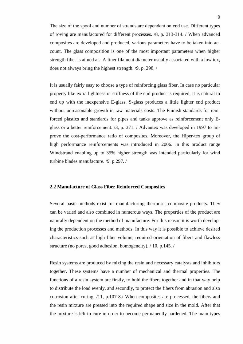
of processing illustrated by Figure 4 are: contact molding, filament winding, pressure
bag molding, pultrusion, matched-die-molding and continuous laminating. The pro-
cessing can also be divided into open mold processing and closed mold processing. In
the former only one mold is applied and the material is in contact with the mold on
one surface only. The technique is frequently exploited in civil engineering applica-
tions. In the case of closed mold processing, the product is formed inside a closed
space formed by two molds. Open mold processes are manual, with the exception of
filament winding, whereas closed mold processes are semi-automatic or automatic.
/12, p. 331-2. /
FIGURE 4. The main types of processing glass fiber /12, p. 332/
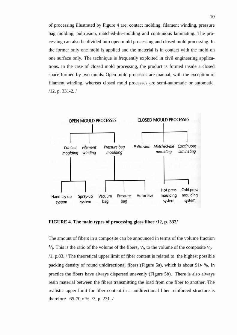
The amount of fibers in a composite can be announced in terms of the volume fraction
Vf. This is the ratio of the volume of the fibers, vf, to the volume of the composite vc.
/1, p.83. / The theoretical upper limit of fiber content is related to the highest possible
packing density of round unidirectional fibers (Figure 5a), which is about 91v %. In
practice the fibers have always dispersed unevenly (Figure 5b). There is also always
resin material between the fibers transmitting the load from one fiber to another. The
realistic upper limit for fiber content in a unidirectional fiber reinforced structure is
therefore 65-70 v %. /3, p. 231. /
11
(a) (b)
FIGURE 5 (a) and (b). The theoretical highest possible packing density of round
unidirectional fibers in a composite (a) and the typical packing density of fibers
in practice (b) /3, p. 231/
The weight fraction, Wf is related to the volume fraction in the following way:
= = , (1)
where ρ is the density, and the subscripts f and c refer to fibers and composites /1, p.
83/. Weight fractions play a key role, e.g. when raw materials are measured out. In the
context of the study of mechanical properties it is essential to know the volume frac-
tions. When composites are manufactured, it is frequently necessary to convert weight
fractions into volume fractions and vice versa. In normally used laminates the density
of the reinforcement is nearly always higher than that of the matrix-resin combination.
/3, p. 231-2. / Table 2 shows how the characteristics of polyamide are affected by the
fiber content.
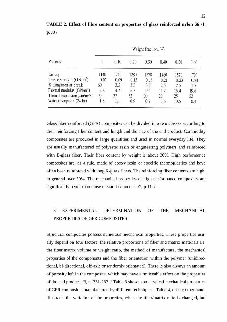
12
TABLE 2. Effect of fibre content on properties of glass reinforced nylon 66 /1,
p.83 /
Glass fiber reinforced (GFR) composites can be divided into two classes according to
their reinforcing fiber content and length and the size of the end product. Commodity
composites are produced in large quantities and used in normal everyday life. They
are usually manufactured of polyester resin or engineering polymers and reinforced
with E-glass fiber. Their fiber content by weight is about 30%. High performance
composites are, as a rule, made of epoxy resin or specific thermoplastics and have
often been reinforced with long R-glass fibers. The reinforcing fiber contents are high,
in general over 50%. The mechanical properties of high performance composites are
significantly better than those of standard metals. /2, p.11. /
3 EXPERIMENTAL DETERMINATION OF THE MECHANICAL
PROPERTIES OF GFR COMPOSITES
Structural composites possess numerous mechanical properties. These properties usu-
ally depend on four factors: the relative proportions of fiber and matrix materials i.e.
the fiber/matrix volume or weight ratio, the method of manufacture, the mechanical
properties of the components and the fiber orientation within the polymer (unidirec-
tional, bi-directional, off-axis or randomly orientated). There is also always an amount
of porosity left in the composite, which may have a noticeable effect on the properties
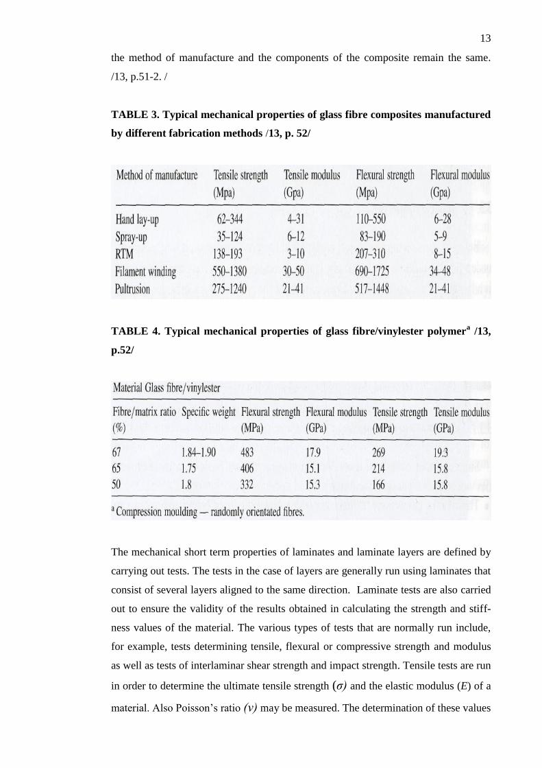
of the end product. /3, p. 231-233. / Table 3 shows some typical mechanical properties
of GFR composites manufactured by different techniques. Table 4, on the other hand,
illustrates the variation of the properties, when the fiber/matrix ratio is changed, but
13
the method of manufacture and the components of the composite remain the same.
/13, p.51-2. /
TABLE 3. Typical mechanical properties of glass fibre composites manufactured
by different fabrication methods /13, p. 52/
TABLE 4. Typical mechanical properties of glass fibre/vinylester polymera /13,
p.52/
The mechanical short term properties of laminates and laminate layers are defined by
carrying out tests. The tests in the case of layers are generally run using laminates that
consist of several layers aligned to the same direction. Laminate tests are also carried
out to ensure the validity of the results obtained in calculating the strength and stiff-
ness values of the material. The various types of tests that are normally run include,
for example, tests determining tensile, flexural or compressive strength and modulus
as well as tests of interlaminar shear strength and impact strength. Tensile tests are run
in order to determine the ultimate tensile strength (σ) and the elastic modulus (E) of a
material. Also Poisson’s ratio (ν) may be measured. The determination of these values
14
is of particular importance, since the stiffness of the material is essentially represented
by its elastic modulus and Poisson’s ratio. /3, p. 294. / The experimental part of the
present thesis concentrates solely on static tensile tests. In the following, however,
both static and fatigue tensile tests, will be discussed in more detail.
3.1 Tensile Tests
In general, strength refers to the ability of a structure to resist loads without failure.
Failure can take place because of rupture due to excessive stress. It may also occur as
a result of excessive deformation. Tensile properties refer to the ability of materials to
resist pulling or stretching forces. Tests are performed in order to define the load-
deformation behavior of materials. The tensile test is started by mounting the speci-
men in a testing machine grips. The loading rate varies depending on the standard
between 2-10 mm/min. An electromechanical extensometer is attached on the speci-
men to measure the extension (elongation) that will take place over the gage length.
Before testing the specimen is marked in order to define the original gage length, L0.
Gage length is not equal to specimen length. An axial load P causes an elongation in
the specimen between the gage marks. While the specimen is pulled, the testing ma-
chine measures and records the load P. In many cases the extensometer directly
measures the elongation Δ L, where L* is the length of the deformed test specimen:
L0 (2)
A stress-strain diagram can be plotted by using the values of stress and extensional
strain. The values used are the engineering stress (σ) i.e. the load divided by the origi-
nal cross-sectional area of the test section, and the engineering strain (ε) i.e. the elon-
gation divided by the original gage length:
, (3)
It is possible to deduce the elastic modulus of a material by reading the stress-strain
diagram. The ratio of stress to strain in a chosen linear region of the diagram is called
the elastic modulus. It is obtained by:
15
(4)
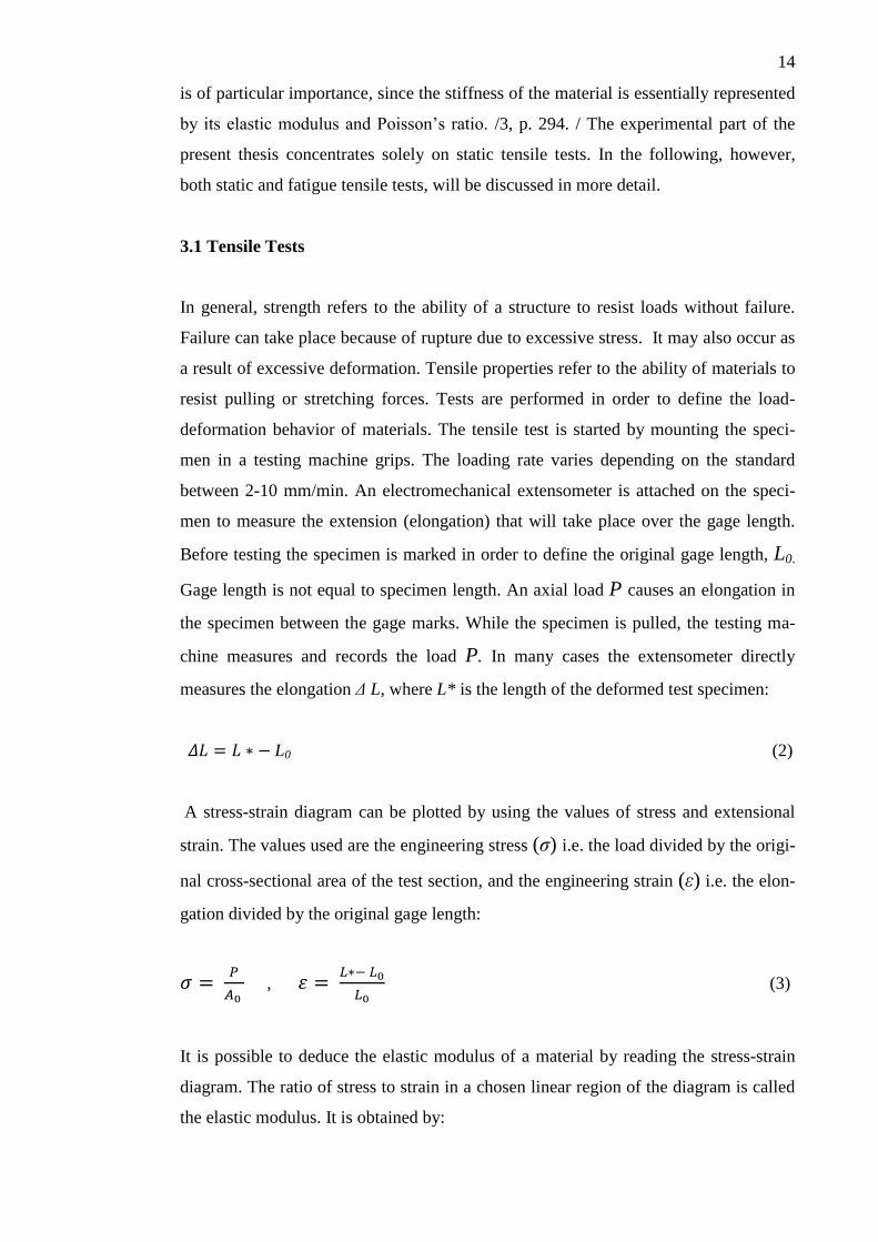
The interpretation of a stress-strain curve can be of valuable use in predicting material
behavior in different engineering structures. /14, p.36-41./ Figure 6 presents a stress-
strain curve including the features that are typically found in a loading curve.
FIGURE 6. A stress-strain curve /15, p.64/
The tensile strength (ultimate strength), tensile modulus (elastic modulus), and elonga-
tion (ultimate strain) can thus all be obtained from the normal tensile-strain test. The
condition of stress here represents uniaxial tension. Also Poisson’s ratio (ν) can give
valuable information. It refers to ‘the ratio of lateral unit strain (Δ to longitudinal
unit strain ( under the condition of uniform and uniaxial longitudinal stress with-
in the proportional limit’ /16, p. 9/ and can be obtained as follows:
(5)
There are three possible ways to calculate the elastic modulus from a non-linear load-
ing curve shown in Figure 6. First, the modulus may be taken as a tangent to the initial
part of the curve. Secondly, a tangent can be constructed at a specified strain level.
The third option is constructing a secant between points A and B. Poisson’s ratio may
also be calculated in case longitudinal and transverse data are obtained. The same up-
per and lower strain limits as in the case of calculating the elastic modulus can be ap-
plied. / 15, p.65. /
16
As regards to anisotropic composites, the tensile properties differ in the fiber and the
cross-fiber direction. They are obtained by applying samples which are cut with their
long axis parallel to the fiber direction. As a rule, tensile specimens are always pulled
in the long direction. /6, p.197/
The manufacture and application of test specimens in tensile tests are discussed in
Chapter 6.
3.2 Fatigue Tests
Fatigue refers to the degradation or failure of the mechanical properties of material
after repeated application of strain. In the case of composites, owing to the anisotropic
nature of the material, a complex failure mechanism is involved and severe damage
may be caused. It is important to be able to predict the fatigue behavior of composite
materials to be able to design and manufacture structures that can tolerate damage as
well as possible. For this purpose also the long-term properties of composites should
be taken into account. This can be done if the basic mechanisms of material degrada-
tion under mechanical loads are recognized. /13, p. 55. /
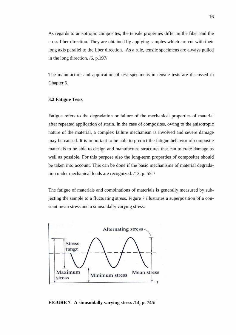
The fatigue of materials and combinations of materials is generally measured by sub-
jecting the sample to a fluctuating stress. Figure 7 illustrates a superposition of a con-
stant mean stress and a sinusoidally varying stress.
FIGURE 7. A sinusoidally varying stress /14, p. 745/
17
Fatigue tests are in most cases tensile or tension/compression tests, in some cases also
flexural tests. The specimens used in fatigue tests are similar to those applied in static
testing. The development of fatigue under static and fatigue loading is basically of the
same nature. The difference lies in the fact that fatigue loading at a certain stress level
is going to cause extra damage. This additional damage will depend on the cycle fre-
quency. /13, p. 55. /
3.3 S-N Relationship
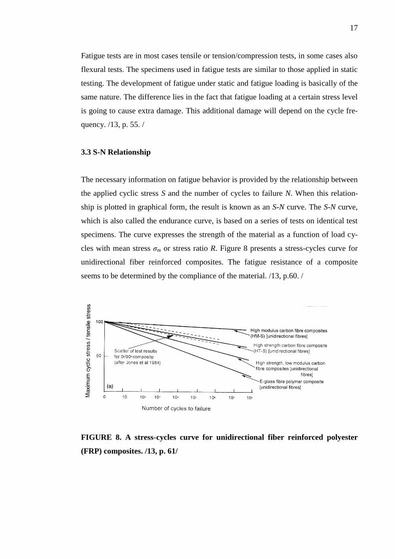
The necessary information on fatigue behavior is provided by the relationship between
the applied cyclic stress S and the number of cycles to failure N. When this relation-
ship is plotted in graphical form, the result is known as an S-N curve. The S-N curve,
which is also called the endurance curve, is based on a series of tests on identical test
specimens. The curve expresses the strength of the material as a function of load cy-
cles with mean stress σm or stress ratio R. Figure 8 presents a stress-cycles curve for
unidirectional fiber reinforced composites. The fatigue resistance of a composite
seems to be determined by the compliance of the material. /13, p.60. /
FIGURE 8. A stress-cycles curve for unidirectional fiber reinforced polyester
(FRP) composites. /13, p. 61/
18
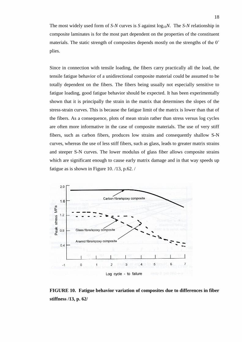
The most widely used form of S-N curves is S against log10N. The S-N relationship in
composite laminates is for the most part dependent on the properties of the constituent
materials. The static strength of composites depends mostly on the strengths of the 0˚
plies.
Since in connection with tensile loading, the fibers carry practically all the load, the
tensile fatigue behavior of a unidirectional composite material could be assumed to be
totally dependent on the fibers. The fibers being usually not especially sensitive to
fatigue loading, good fatigue behavior should be expected. It has been experimentally
shown that it is principally the strain in the matrix that determines the slopes of the
stress-strain curves. This is because the fatigue limit of the matrix is lower than that of
the fibers. As a consequence, plots of mean strain rather than stress versus log cycles
are often more informative in the case of composite materials. The use of very stiff
fibers, such as carbon fibers, produces low strains and consequently shallow S-N
curves, whereas the use of less stiff fibers, such as glass, leads to greater matrix strains
and steeper S-N curves. The lower modulus of glass fiber allows composite strains
which are significant enough to cause early matrix damage and in that way speeds up
fatigue as is shown in Figure 10. /13, p.62. /
FIGURE 10. Fatigue behavior variation of composites due to differences in fiber
stiffness /13, p. 62/
19
The fatigue failure of materials is a random phenomenon. The result of this is that
however carefully controlled the experiments are, at any selected amplitude, often a
larger scatter in the number of cycles to failure occurs than had been predicted. There
is a good reason for this. It relates to the fact that even though it is convenient to con-
sider a material homogeneous, on a microscopic scale things appear differently. If the
material is studied carefully, it becomes evident that it contains a number of internal
defects such as microcracks, dislocations etc. When the same cyclic stress amplitude
is applied to specimens, which appear identical, it is highly unlikely that each of them
will fail after exactly the same number of stress cycles. In reality the conditions of the
fatigue cracks in each specimen differ greatly. For this reason, although fatigue data is
generally presented as a single plot on an S-N curve, it should be understood that this
plot should not be regarded as an exact prediction of a material’s fatigue life at a given
stress amplitude. S-N curves are usually created on the basis of a large number of test
results which have been analyzed by applying a statistical method. / 17, p. 550-1. /
Most of the methods were developed to be used for metallic structures. In the context
of composite structures, they have to be modified so that the special features of com-
posite damage could be taken into consideration. Several studies related to the struc-
tural safety and reliability of composites exploit the Weibull distribution (See e.g. 7,
p.733-734) to describe the statistical variability of the strength and fatigue life of the
materials. /18, p. 17-18. /
4 DEFINITION OF LAMINATE PROPERTIES BY CALCULATION MODELS
In the following some of the properties of basic laminate structures will be considered,
first on the basis of micromechanical models and later from a macromechanical point
of view. The micromechanical models concentrate on the behavior of fiber reinforced
layers. They are applied to predict the characteristics of composite materials. The
properties of both fiber and matrix have to be considered. The approach is known to
be successful in predicting the stiffness properties of materials. The models for com-
posite strength have not been equally effective. /5, p.61. /
4.1 Longitudinal Modulus
20
In the case of an isotropic material, stiffness is exclusively represented by the modulus
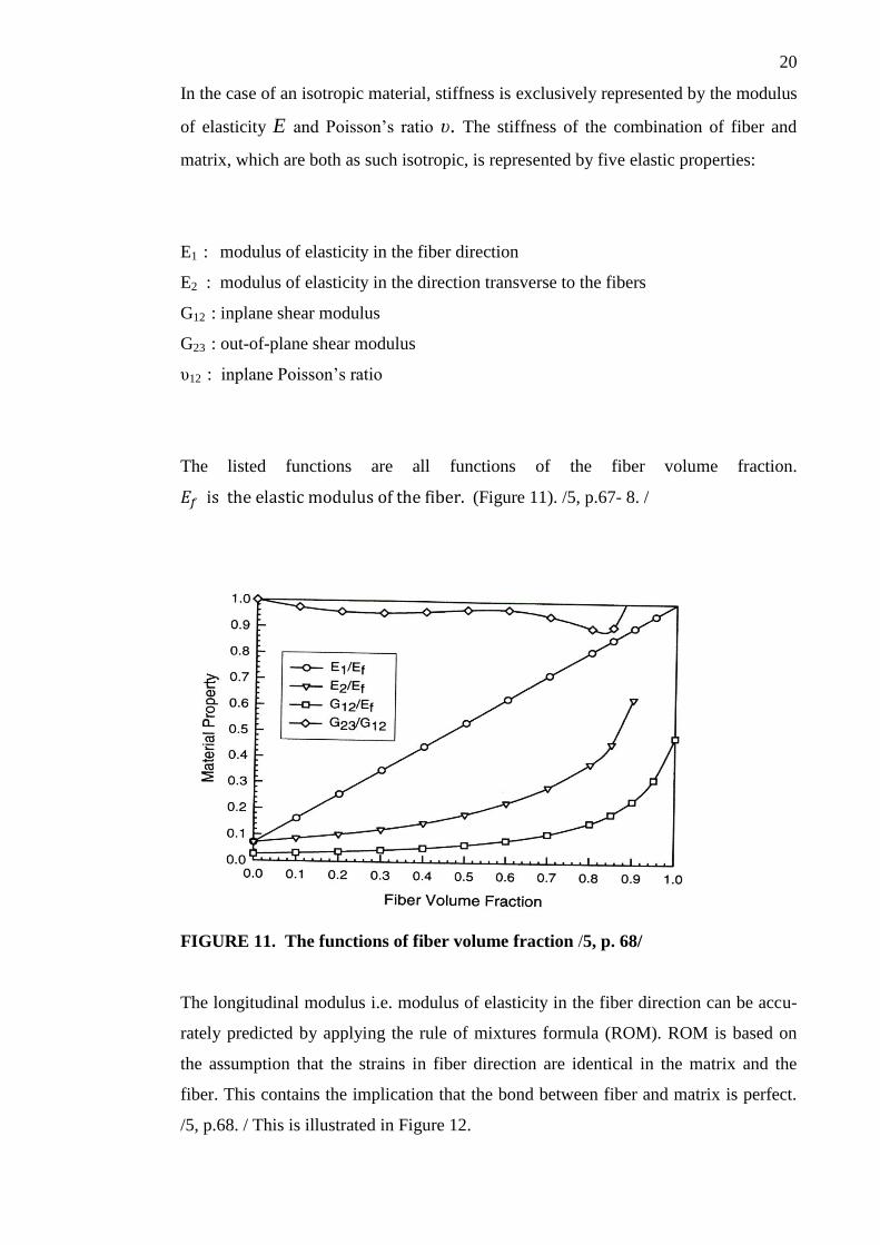
of elasticity E and Poisson’s ratio υ. The stiffness of the combination of fiber and
matrix, which are both as such isotropic, is represented by five elastic properties:
E1 : modulus of elasticity in the fiber direction
E2 : modulus of elasticity in the direction transverse to the fibers
G12 : inplane shear modulus
G23 : out-of-plane shear modulus
υ12 : inplane Poisson’s ratio
The listed functions are all functions of the fiber volume fraction.
(Figure 11). /5, p.67- 8. /
FIGURE 11. The functions of fiber volume fraction /5, p. 68/
The longitudinal modulus i.e. modulus of elasticity in the fiber direction can be accu-
rately predicted by applying the rule of mixtures formula (ROM). ROM is based on
the assumption that the strains in fiber direction are identical in the matrix and the
fiber. This contains the implication that the bond between fiber and matrix is perfect.
/5, p.68. / This is illustrated in Figure 12.
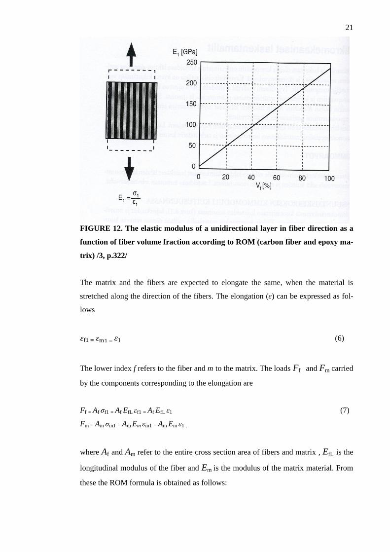
21
FIGURE 12. The elastic modulus of a unidirectional layer in fiber direction as a
function of fiber volume fraction according to ROM (carbon fiber and epoxy ma-
trix) /3, p.322/
The matrix and the fibers are expected to elongate the same, when the material is
stretched along the direction of the fibers. The elongation (ε) can be expressed as fol-
lows
ε1 (6)
The lower index f refers to the fiber and m to the matrix. The loads Ff and Fm carried
by the components corresponding to the elongation are
Ff = Af σf1 = Af EfL εf1 = Af EfL ε1 (7)
Fm = Am σm1 = Am Em εm1 = Am Em ε1 ,
where Af and Am refer to the entire cross section area of fibers and matrix , EfL is the
longitudinal modulus of the fiber and Em is the modulus of the matrix material. From
these the ROM formula is obtained as follows:
22
= = = (8)
=VfEfL + VmEm = VfEfL + (1 – Vf) Em ,
where Vf and Vm are the relative proportions of fibers and matrix in the cross section
i.e. the volume fractions of the components. According to the formula, the longitudi-
nal modulus in fiber direction is obtained by adding together the moduli of the rein-
forcement and the matrix in the proportion of their volume fraction. On the whole,
longitudinal modulus tends to be a fiber dominated property. The stiffness of the ma-
terial increases linearly while the volume fraction of the reinforcing fiber increases. /3,
p. 321-2; 5, p. 69-70. /
4.2 Longitudinal Tensile Strength
It is possible to postulate the simplest imaginable model for the tensile strength of a
continuous fiber reinforced composite by assuming that all the fibers have exactly the
same tensile strength. Even though in reality the strength of all fibers is not similar, it
is also assumed here that the strength of all the fibers is the fiber average strength σ fa.
Secondly, it is assumed that the fibers and the matrix both behave linearly until fail-
ure. Most polymers do not actually behave in this way, since their load-rate dependen-
cy creates further complications. The third theoretical assumption considers fibers
brittle in respect to the matrix. This doesn’t always hold true e.g. in the case of E-
glass, which outstands most resins when elongation to failure is investigated. The
fourth assumption is not merely theoretical: fibers are stiffer than the matrix in the
case of materials other than ceramic matrix composites. If these four assumptions are
realized, the composite is likely to break as soon as the stress to which the fibers are
subjected reaches their strength σfa. After that the matrix cannot carry the load. Con-
sequently, the composite elongation to failure εcu is identical with the fiber elongation
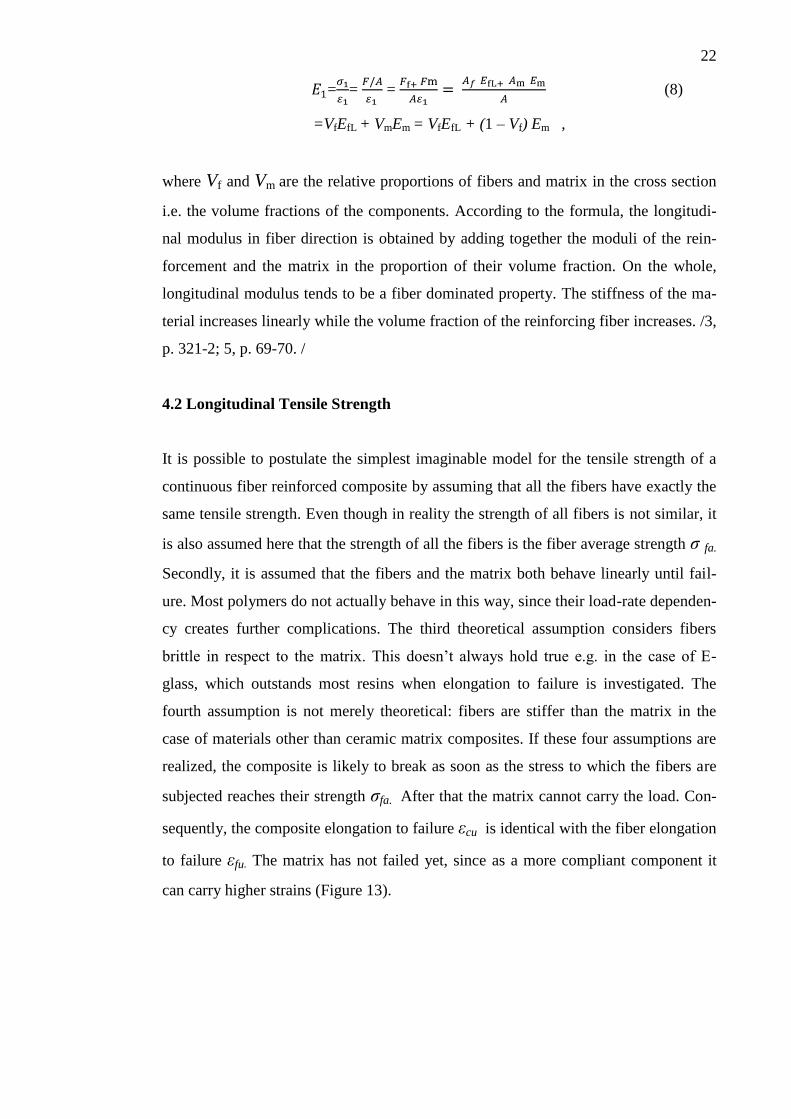
to failure εfu. The matrix has not failed yet, since as a more compliant component it
can carry higher strains (Figure 13).
23
FIGURE 13. Micromechanics of the strength of a fiber reinforced composite
when uniform fiber strength is assumed /5, p. 86/
It can therefore be assumed that the longitudinal tensile strength is dependent on the
strength of fibers. This is represented by the following formula:
= σfaVf + σm*(1 – Vf ) , (9)
where the stress in the matrix at failure is
σm* = σfa Em/Ef (10)
The tensile strength is thus
= σfa [Vf + Em/Ef (1 – Vf)] (11)
The assumption in the above equation is that the strain in the matrix and fibers is simi-
lar. It is also implied that once the fibers fail, the matrix cannot sustain the load. This
will lead to the failure of the composite. In the case of composites with particularly
low fiber volume fraction, the matrix may be able to carry the load after the fiber fail-
ure. /5, p. 85-6. /
24
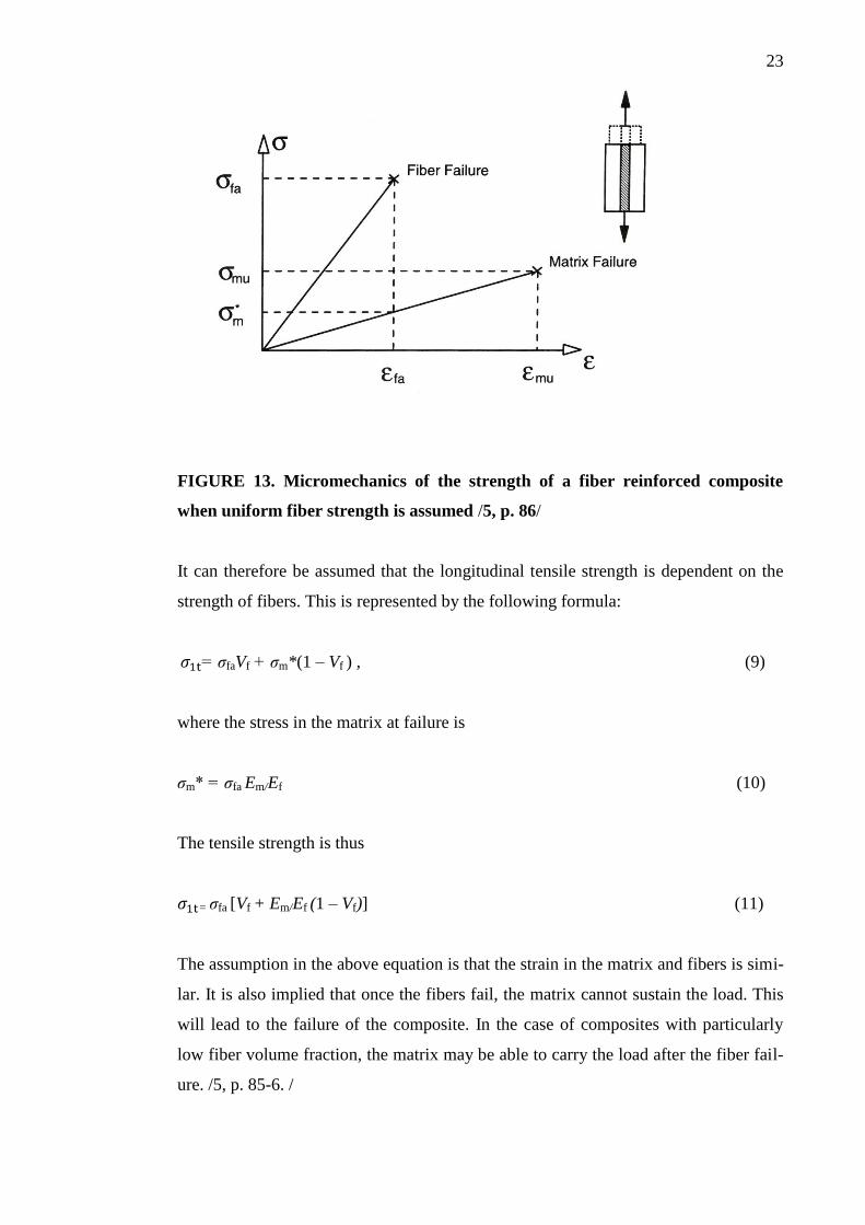
4.3 Macromechanics of the Orthotropic Layer
Macromechanics can be defined as the study of the behavior of composite materials,
which starts with the assumption that the material is homogeneous. The properties of
the material components are regarded as those of the composite as a whole. /19, p.85. /
Composite structures which are built to be used in practical applications are generally
built with laminates that have several layers with more than one orientation. The ori-
entations of the layers have to be considered in laminate fabrication. The purpose is to
produce laminates that can carry loads. That is why such orientations are chosen that
provide the highest values of strength and stiffness.
Composite materials are significantly stronger and stiffer in fiber direction than in
other directions. Every fiber reinforced composite layer can be considered orthotropic
in material axes (see Chapter 2). A unidirectional fiber-reinforced composite which
has three planes of symmetry that coincide with the coordinate planes may be consid-
ered orthotropic. One plane of symmetry is perpendicular to the fiber direction, and
the other two can be any pair of planes orthogonal to the fiber direction and among
themselves. /5, p.66 -7. / (Figure 14).
FIGURE 14. The principal planes 12, 13 and 23 of an orthotropic FRP layer /3,
p.326/
The following constants are required to describe an orthotropic material:
- elastic moduli E1, E2 ja E3, which indicate the tensile and compressive strength
in axial loading to directions 1, 2 and 3
25
- Poisson’s ratios νij; ij = 12, 13 and 23, which indicate the strain in the j-
direction when stressed in the i-direction
- shear moduli G12, G13 ja G23, which indicate the shear strength, when planes
12, 13 and 23 are under stress
The behavior of a linear elastic orthotropic layer can be determined by applying five
elastic moduli: E1 and E2 in the main directions, shear modulus (G12), and Poisson’s
ratios (ν12 and ν21). Four of these are independent, but the moduli and Poisson’s ratios
can be connected by deduction.
E1 ν21 = E2 ν12 (12)
The values of the elastic moduli can be calculated, when the properties of the compo-
nents of the composite material and the structure are known. If necessary, more accu-
rate values are determined experimentally. /3, p. 326. /
Fiber reinforced materials are, as a rule, laminated into plates and panels that consti-
tute the actual basic items of engineering structures. So far the analyses of these struc-
tures have mainly been based on either theories that were originally developed for
isotropic materials or on the “classical lamination theory” (CLT). The theory consists
of a number of formulas and equations which can be applied to analyze the stress-
strain behavior of individual lamina as well as to calculate the stiffness of a laminate.
/19, p.147-156; 4, p. 217-228. / However, the classical theory has proved unsatisfacto-
ry, for example in the interpretation of inter-laminar behavior. Numerous compensat-
ing theories have been proposed to overcome the limitations of these attempts to char-
acterize laminate behavior. Computational techniques make it possible to adopt a
three-dimensional approach to the challenge of analyzing laminated composite mate-
rials. 3D analytical modeling is able to take into account three-dimensional variations
of stresses and strains and thus provide more accurate predictions of material behav-
ior. Analyses include equilibrium equations of stresses, strain-displacement relations
and stress-strain relations.
26
5 FATIGUE OF LAMINATES AND DESIGN CRITERIA FOR COMPOSITE
STRUCTURES
As a rule, reinforced fiber composites are subject to progressive fatigue degradation
because of failure of the fibers, fiber stacking sequence or type of fatigue loading. The
damage propagation under fatigue and static loading is similar except that the fatigue
loading at a given stress level will cause extra damage. This will obviously be de-
pendent on the cycle frequency. Four principal failure mechanisms of polymeric com-
posites under fatigue loading can be recognized: fiber breakage due to interface
debonding, matrix cracking, interface shear failure with fiber pull-out and brittle fail-
ure.
These failure mechanisms may also occur as combinations causing fatigue damage
resulting in reduced fatigue strength and stiffness. When fatigue stress is high, cracks
can initiate during the first loading cycle and accumulate with increasing number of
cycles. /13, p. 56. /
When subjected to tensile loads, unidirectional continuous fiber composites have good
fatigue properties that are typically linear to failure when loaded parallel to the longi-
tudinal fiber. Advanced fiber composites under tensile stress in the fiber direction are
insensitive to fatigue even at stresses which approach the static fracture strength. For
other types of stresses and with other fiber orientations the fatigue of composites may
be even more complicated than that of metals. /18, p. 25. / If the composite contains
off axes plies, numerous damage mechanisms may occur under loading. The internal
load is redistributed and the stress-strain response becomes non-linear. /13, p. 55. /
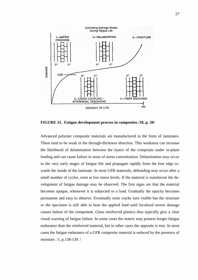
Figure 15 illustrates an interpretation of fatigue development process in composites.
Two major stages can be differentiated. Firstly, individual plies experience homoge-
neous and non-interactive cracking. The second stage consists of damage in zones of
crack interaction which is increasing. The Characteristic Damage State (CDS) is the
point where transition from the first stage to the second stage occurs. CDS is charac-
terized by a clear crack pattern. According to this model the evolution of damage in a
composite laminate generally progresses from initial matrix cracking and crack cou-
pling/interfacial debonding to states of delamination and fiber breaking, the final state
being fracture of the composite material. /18, p. 20. /
27
FIGURE 15. Fatigue development process in composites /18, p. 20/
Advanced polymer composite materials are manufactured in the form of laminates.
These tend to be weak in the through-thickness direction. This weakness can increase
the likelihood of delamination between the layers of the composite under in-plane
loading and can cause failure in areas of stress concentration. Delamination may occur
in the very early stages of fatigue life and propagate rapidly from the free edge to-
wards the inside of the laminate. In most GFR materials, debonding may occur after a
small number of cycles, even at low stress levels. If the material is translucent the de-
velopment of fatigue damage may be observed. The first signs are that the material
becomes opaque, whenever it is subjected to a load. Gradually the opacity becomes
permanent and easy to observe. Eventually resin cracks turn visible but the structure
or the specimen is still able to bear the applied load until localized severe damage
causes failure of the component. Glass reinforced plastics thus typically give a clear
visual warning of fatigue failure. In some cases the matrix may possess longer fatigue
endurance than the reinforced material, but in other cases the opposite is true. In most
cases the fatigue endurance of a GFR composite material is reduced by the presence of
moisture. /1, p.138-139. /
28
5.1 The Effect of Reinforcement on Laminate Fatigue
Bare reinforcing fibers are generally tested by fiber manufacturers as part of quality
control procedure. Even though the properties of a composite as a whole are decisive,
testing fibers by running different physical, chemical and mechanical tests is seen as a
necessary method of developing and screening composites. /6, p.186./ On the whole,
fiber reinforced composites exhibit high values of tensile strength. Fibers typically
possess a lower strain-to-failure value than the matrix. Fracture of a composite materi-
al generally occurs when the fibers fail. The interpretation of reinforcement behavior
is, however, not straightforward. A problem is created by the variability of fiber
strength. High strength filaments characteristically differ from each other in this re-
spect. Varying fiber strengths result in two important consequences. First, the strength
of a group of fibers is not equal to the sum of the strengths of the fibers in question.
Neither is it the mean strength of the fibers. Secondly, fibers that are first to break
under loading simultaneously initiate a chain reaction. Perturbations of the stress field
will appear near the break. This will bring along fiber-matrix interface shear stresses
that will transfer the load across the interface. Stress concentrations are introduced to
neighboring unbroken fibers. Stress distribution described above may be the cause of
several modes of failure.
Fiber tensile strength is usually given in the form of the average strength of a group of
fibers representing a particular fiber type. In practice the determination of the strength
is carried out by impregnating a bundle of the fibers in question with a polymer and
loading it to failure. The average fiber strength, which is obtained in this way, is de-
fined by the maximum load divided by the cross-sectional area of the fibers. /7, p.192-
3./ The maximum strength that has been measured in single fiber tests (ASTM D3379)
may yield values reaching 3,5 GPa for E-glass and 4,8 GPa in the case of S-glass.
Values like this cannot, however, be realized in a composite. There are factors in-
volved in the numerous stages of processing that reduce the strength of fibers to ap-
proximately 1,75 GPa for E-glass and 2,10 GPa for S-glass. /5, p.18. /
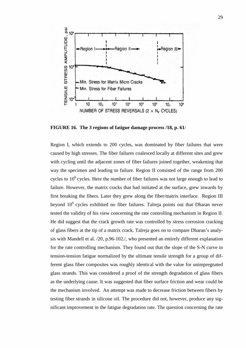
Talreja /18, p.61-2/ discusses the investigation of fatigue damage in unidirectional
glass/epoxy composites reported by Dharan (1975), who described the way in which
damage process falls in three regions along the fatigue life axis (Figure 16).
29
FIGURE 16. The 3 regions of fatigue damage process /18, p. 61/
Region I, which extends to 200 cycles, was dominated by fiber failures that were
caused by high stresses. The fiber failures coalesced locally at different sites and grew
with cycling until the adjacent zones of fiber failures joined together, weakening that
way the specimen and leading to failure. Region II consisted of the range from 200
cycles to 106
cycles. Here the number of fiber failures was not large enough to lead to
failure. However, the matrix cracks that had initiated at the surface, grew inwards by
first breaking the fibers. Later they grew along the fiber/matrix interface. Region III
beyond 106
cycles exhibited no fiber failures. Talreja points out that Dharan never
tested the validity of his view concerning the rate controlling mechanism in Region II.
He did suggest that the crack growth rate was controlled by stress corrosion cracking
of glass fibers at the tip of a matrix crack. Talreja goes on to compare Dharan’s analy-
sis with Mandell et al. /20, p.96-102./, who presented an entirely different explanation
for the rate controlling mechanism. They found out that the slope of the S-N curve in
tension-tension fatigue normalized by the ultimate tensile strength for a group of dif-
ferent glass fiber composites was roughly identical with the value for unimpregnated
glass strands. This was considered a proof of the strength degradation of glass fibers
as the underlying cause. It was suggested that fiber surface friction and wear could be
the mechanism involved. An attempt was made to decrease friction between fibers by
testing fiber strands in silicone oil. The procedure did not, however, produce any sig-
nificant improvement in the fatigue degradation rate. The question concerning the rate
30
controlling mechanism in Region II of fatigue of GFR composites was not satisfactori-
ly solved by either of these studies. /18, p. 61-2. /
5.2 The Effect of the Environment of Use on Fatigue Strength
The environmental durability of a composite structure is an essential issue in the de-
velopment of reinforced materials. The data collected from studies concerning the
subject has mainly focused on the aircraft and ship industries during the past four dec-
ades.
Tsai /21, p.749-767/ presents a list of the major degradation mechanisms caused by
environmental exposure. The first to be mentioned is the loss of strength of the rein-
forcing fibers due to a stress-corrosion mechanism. Another important mechanism
consists of the degradation of the fiber-matrix interface, which results in the loss of
both adhesion and interfacial bond strength. The third major factor is connected to the
previous two, namely the permeability of the matrix material to corrosive agents, for
example water vapor. The fourth phenomenon is related to the viscoelastic depend-
ence of matrix modulus and strength on time and temperature. In addition to the above
mechanisms caused by environmental effects, there is the combined influence of tem-
perature and moisture accelerated degradation.
Composite materials should ideally survive in various environments. While subjected
to the above mentioned mechanisms of degradation they may be exposed to e.g. hu-
midity or water immersion, salt spray, temperature variation, fire, in some cases also
jet fuel, hydraulic fluid or stack gas. Humidity or water immersion may lead to de-
graded stiffness and strength. In most cases the fatigue endurance of a GFR polymer is
reduced by the presence of moisture. /1, p.139/. The tensile strength of composite
materials is lowered by chemical corrosion. The corrosion resistance of a material is
dependent on the composition of the material and the time of exposure. /5, p.18. /
Temperature is undoubtedly one of the prime environmental factors affecting the me-
chanical properties of GFR laminates. The thermal durability of fibers depends on
their type. The tensile strength of glass fibers reduces at elevated temperatures but can
be considered constant up to 275˚C. The durability of the composite material depends
on the matrix type /5, p.18/. Therefore, in the case of usual laminates, the thermal
durability is restricted by the matrix resin, which will soften at increased temperatures.
31
Decrease of temperature will increase the stiffness and also to some extent the
strength of the matrix and make it brittle. Since the reinforcing fibers and the matrix
polymer in most cases possess different coefficients of thermal expansion, changes in
temperature characteristically induce additional strains in the structure. /10, p. 142-3. /
Humidity may soften the matrix polymer and affect its mechanical properties. It can
produce swelling strain in the structure. Particularly the edges of the laminate allow
moisture to proceed into the structure along the fiber-matrix interface and destroy the
fiber-matrix bond. All in all, hygrothermal strain due to thermal expansion and swell-
ing strain caused by moisture, is often responsible for changes in the measurements
and shape of a laminate structure. /10, p. 167. /
5.3 Design Criteria for Composite Structures
When components made of composite material are designed, both material design and
structural design are involved, in many cases simultaneously. Important properties
such as stiffness and thermal expansion may be varied during the process. The proper-
ties of fibers and matrix materials may be combined and thus achieve the desired val-
ues. Even though micromechanical formulas are excellent at predicting the stiffness of
a material, they are not as successful, when strength is to be determined. For this rea-
son experimental data is essential. Using experimental results in design makes in some
cases micromechanical modeling futile. On the other hand, considerable investments
are required to generate the data. The first stage of designing a structure is to define
the properties of the individual layers of which the laminate consists. The laminate can
be characterized by combining the properties of its layers. If, however, for example in
the case of a particular fiber, the matrix material or the manufacturing process is
changed, unpredictable consequences may result. Thus new and up-to-date experi-
mental data is generally needed for successful design. /5, p.9-10. /
Talreja (18, p.169-179) discusses the progress of damage in composite laminates un-
der mechanical loads and concentrates on the crucial events in the damage process
that should be considered when structures are designed. The criteria that are generally
applied in the case of static loading are the first ply failure criterion and the strength
(total failure) criterion. Composite laminates experience yielding, fracture and insta-
bility when they are subjected to static loads. Among the parameters representing the-
32
se events are yield stress, fracture toughness, critical crack size and buckling stress.
Under static loads, the materials response can be interpreted as initiation of matrix
cracking in one or more plies as the first critical event. The parameter applied in the
definition of this event is the threshold stress (or strain). The last critical event is frac-
ture (separation) of laminate. It is the consequence of fiber failures in plies that are
most closely aligned with the major tensile stress. The parameter used to define this
event is strength. At low constraint, the laminate can sustain a noticeable load beyond
the first ply failure. In the case of full constraint, the laminate fails before there is any
matrix cracking. The deformational response of a structure is, however, mostly deter-
mined by stiffness, which may be considered the potential third criterion. In case the
relationship between crack density and load is determined either by calculation or ex-
perimentally, it is feasible to calculate the degradation of a stiffness property for a
given load. When structural design is based on stiffness degradation, the likelihood of
failure may be defined as the probability of stiffness degradation to a critical value.
There are two main glass fiber composite databases for wind turbine applications. The
first is the DOE/MSU developed in the U.S. by J.F.Mandell and D.D Samborsky , and
the second is the European database. As to trends in glass fiber fatigue behavior the
two databases are mostly in agreement. The DOE/MSU database provides static and
fatigue data for potential blade materials by varying the parameters of fiber content,
fabric architecture and percent in testing potential blade materials. The failure of wind
turbine blades is usually caused by fatigue either by some structural factor or a major
flaw in the material applied. The basis applied in comparing the different materials is
the maximum initial strain which produces a lifetime of 106
cycles. The test programs
carried out may sometimes present results that require a thorough analysis. For exam-
ple, it was discovered in an experiment that the tensile fatigue performance of the test
material became much less fatigue resistant as the fiber volume content was increased
beyond the range of 35-45%. The reason for the sharp decrease in fatigue resistance
while the fiber content was increased evidently lay in the transition to a condition
where the laminate fails due to fatigue immediately after the matrix cracks. The find-
ing was analyzed in the light of results received from a FEM analysis, which showed
that if there is a matrix layer between the fibers of plies next to each other, it may to a
great extent decrease the stress concentration in the 0˚
strands close to the points of
matrix cracking in adjacent plies. While the fiber content is increased, the tight strands
of the fabrics are squeezed together, which in turn leads to matrix crack inducing early
33
failure in tensile fatigue. The designers and manufacturers of wind turbine blades
could thus, on the basis of this analysis, conclude that glass fiber laminates are suscep-
tible to remarkable degradation in their fatigue properties, if fibers are forced very
close to one another. / 22, p. 1-2. /
Nowadays various software tools are applied in the design of wind turbines. The de-
sign of a blade is made easier and more accurate by e.g. interactive 3D visualization,
which provides the designer with immediate feedback of potential changes in the pro-
cess. Material properties as well as layer thicknesses and sequences may be displayed.
The model helps to define the laminate layers and suggests the way they should be
stacked in order to form a successful reinforced structure. Moreover, the blade model
can be subjected to a structural analysis. It is possible to define, for example, strain
and stress based on strength evaluation and carry out fatigue analyses based on time
series./23./
6 STATIC TENSILE TEST OF GLASS FIBER EPOXY COMPOSITE
One of the aims of this thesis was to carry out static tensile tests for two types of uni-
directional laminate, report the results obtained as well as discuss their interpretation
in the light of the theoretical background presented above. In the case of reinforcing
fibers, unidirectional tapes are considered the most adequate form for testing mechan-
ical properties. For this purpose, the cured laminate material is normally machined
into test specimens. /7, p. 285. /
Factors that influence the tensile response of glass fiber reinforced epoxy resin speci-
mens include e.g. the methods of materials preparation, the size and shape of the spec-
imens as well as specimen alignment and gripping. In addition, the application of the
testing method and the testing conditions may affect the results. The desired specimen
dimensions as well as the procedure for preparing and testing the specimens have been
prescribed by various standardization organizations. In this study the International
Standard (ISO) 527-5 instructions for “test conditions for orthotropic and unidirec-
tional fiber-reinforced plastic composites” were applied /24/. In the following a stand-
ard static tensile test and the specimens and test equipment applied in the test will be
34
described. The mechanical properties obtained in the test will be presented in the Ap-
pendix (p. 1-4) and discussed in Chapter 7.
6.1 Test Specimens
The unidirectional glass fiber reinforced laminate plates from which the test speci-
mens were cut were manufactured at Ahlstrom Glassfibre in Mikkeli. The laminate
was prepared by applying vacuum assisted resin infusion (VARIM) (see Ch. 2.2). The
technique consists in applying low pressure to draw the resin into a mold which con-
tains the reinforcing fiber. An airtight vacuum bag functions as a counter mold. The
system was preferred here, because it makes it easier to control fiber orientation. /2, p.
65. / The epoxy resin Hexion 135i was selected. The curing agent was L 137i. The
laminates were structurally orthotropic with all rovings at 0˚direction. Two varieties of
glass fiber were used in the fabrication of the laminates. The fiber volume of both
products was approximately 60%. One of the laminate types to be tested was made by
using traditional E-glass with sizing type R 338, the other contained new generation
high strength glass. The main purpose of carrying out the static tests was to compare
the values of the elastic modulus of the two types of laminate. The hypothesis was that
the high strength glass would outstand the traditional glass fiber as regards to stiffness
i.e. the value of the elastic modulus.
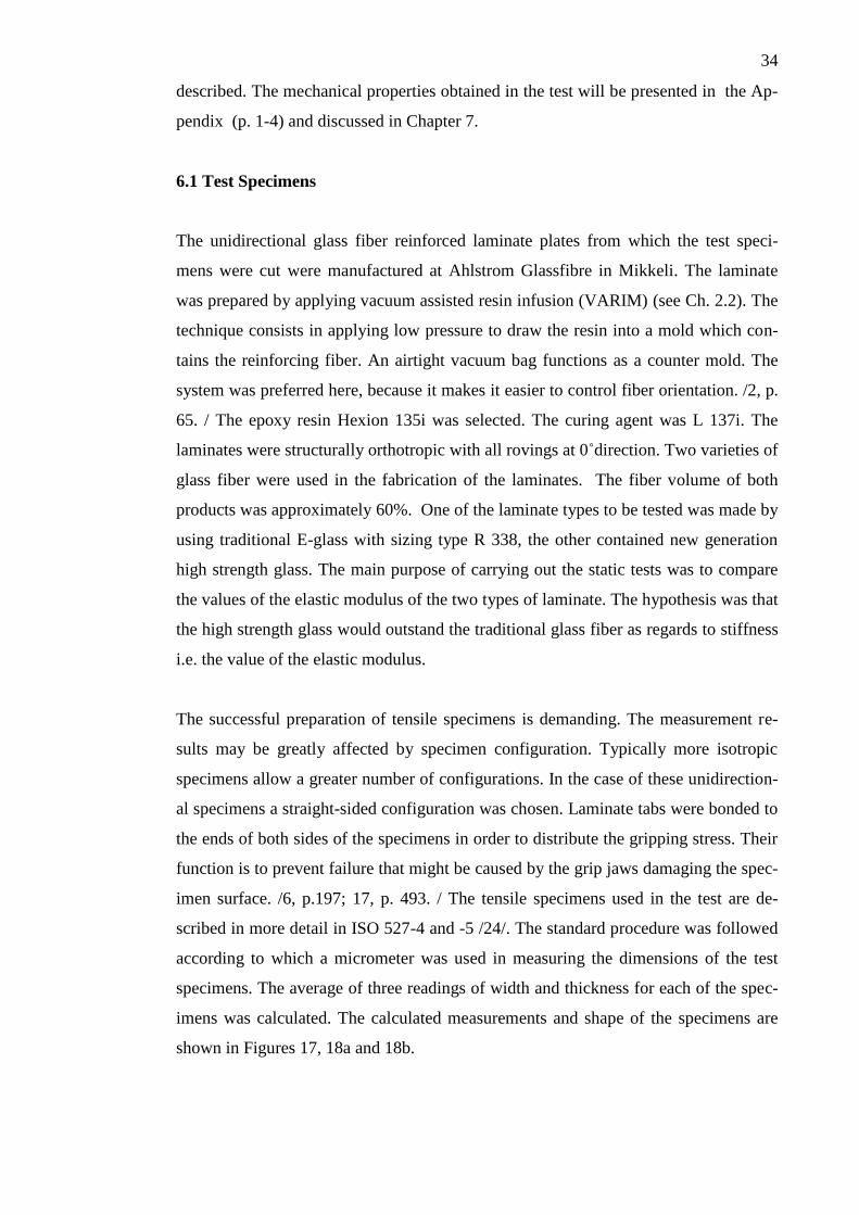
The successful preparation of tensile specimens is demanding. The measurement re-
sults may be greatly affected by specimen configuration. Typically more isotropic
specimens allow a greater number of configurations. In the case of these unidirection-
al specimens a straight-sided configuration was chosen. Laminate tabs were bonded to
the ends of both sides of the specimens in order to distribute the gripping stress. Their
function is to prevent failure that might be caused by the grip jaws damaging the spec-
imen surface. /6, p.197; 17, p. 493. / The tensile specimens used in the test are de-
scribed in more detail in ISO 527-4 and -5 /24/. The standard procedure was followed
according to which a micrometer was used in measuring the dimensions of the test
specimens. The average of three readings of width and thickness for each of the spec-
imens was calculated. The calculated measurements and shape of the specimens are
shown in Figures 17, 18a and 18b.
35
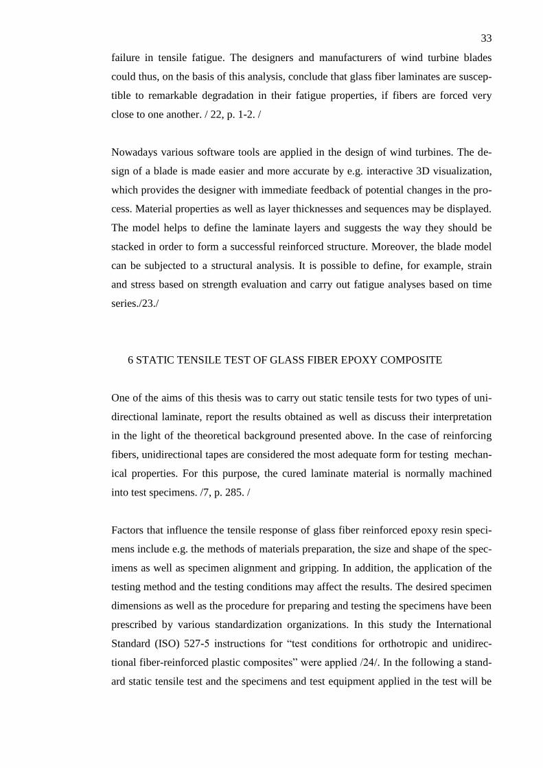
FIGURE 17. Test specimen
average thickness: 1,6 mm
average width: 15,1 mm
length (distance between tabs): 150 mm
FIGURE 18a. Test specimen
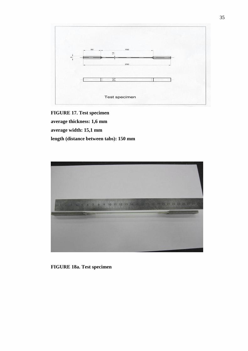
36
FIGURE 18b. Test specimen
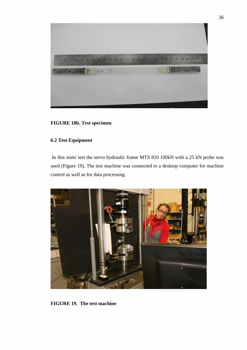
6.2 Test Equipment
In this static test the servo hydraulic frame MTS 810 100kN with a 25 kN probe was
used (Figure 19). The test machine was connected to a desktop computer for machine
control as well as for data processing.
FIGURE 19. The test machine
37
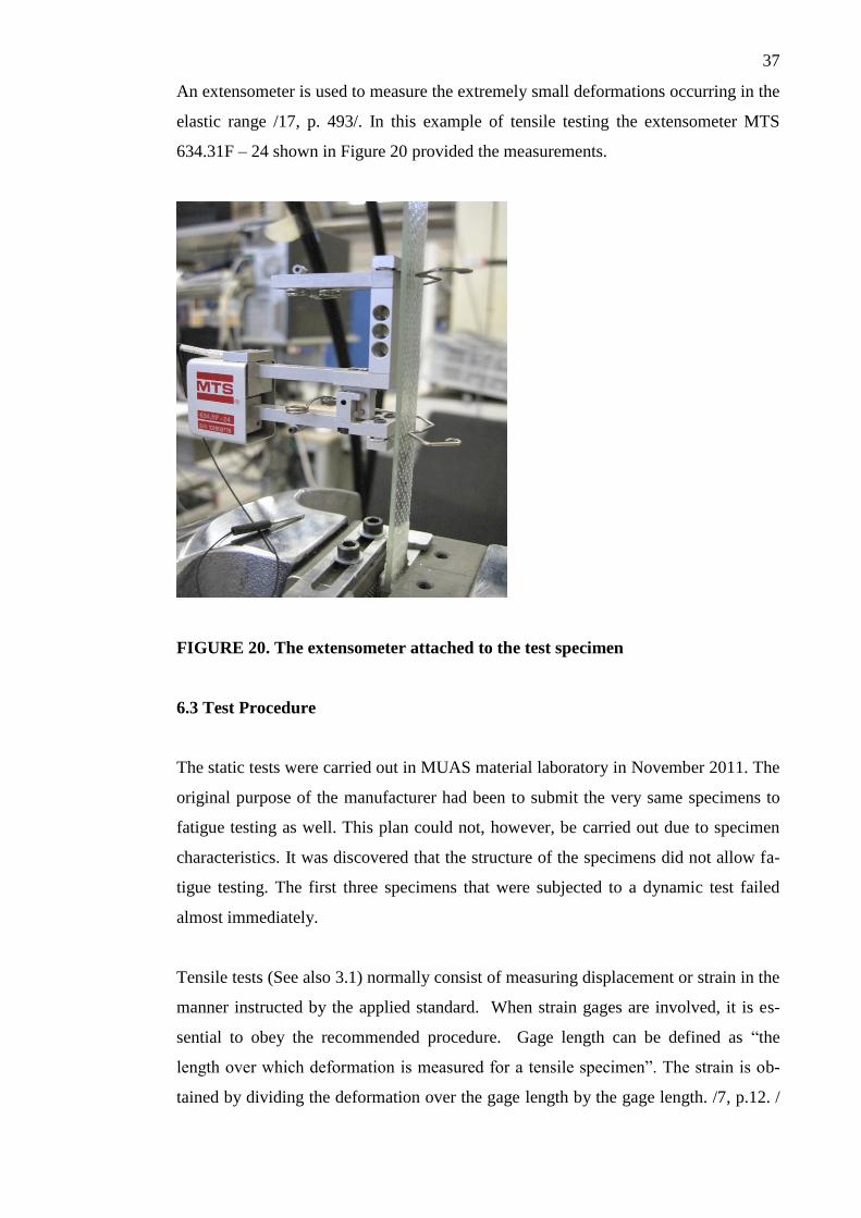
An extensometer is used to measure the extremely small deformations occurring in the
elastic range /17, p. 493/. In this example of tensile testing the extensometer MTS
634.31F – 24 shown in Figure 20 provided the measurements.
FIGURE 20. The extensometer attached to the test specimen
6.3 Test Procedure
The static tests were carried out in MUAS material laboratory in November 2011. The
original purpose of the manufacturer had been to submit the very same specimens to
fatigue testing as well. This plan could not, however, be carried out due to specimen
characteristics. It was discovered that the structure of the specimens did not allow fa-
tigue testing. The first three specimens that were subjected to a dynamic test failed
almost immediately.
Tensile tests (See also 3.1) normally consist of measuring displacement or strain in the
manner instructed by the applied standard. When strain gages are involved, it is es-
sential to obey the recommended procedure. Gage length can be defined as “the
length over which deformation is measured for a tensile specimen”. The strain is ob-
tained by dividing the deformation over the gage length by the gage length. /7, p.12. /
38
The gage length should always be shorter than the length of the specimen. Gages
should also be accurately aligned. A minute misalignment can cause remarkable errors
in the results. The gage length applied in the test was 50 mm.
After the specimen was measured and otherwise prepared and inspected, it was
mounted in the grips of the test machine. It was important to avoid axially stressing
the specimen, while the grips were being tightened. In order to avoid grip failures the
grip pressure was kept low. The centerline of the specimen was aligned with the axis
of the testing machine in order to avoid bending and asymmetric loading. Next the
extensometer was attached onto the center of the specimen and the initial gage length
was measured. As instructed in ISO 527, a displacement rate of 2mm/min was ap-
plied. /15, p. 63. /
The 84 specimens that were tested represented two main types of GFR laminate. The
ones named RA (20 items) and RY (21 items) were prepared from a laminate material
with traditional E-glass reinforcement. Those labeled WA (22 items) and WY (21
items) contained high strength glass, which was assumed to give extra strength and
stiffness to the laminate composite. The static tests that were run, simultaneously pro-
vided the first stage in an investigation, in which the purpose was to examine how the
strength and elastic modulus of particular types of fiber would affect the tension-
tension fatigue of unidirectional laminate material. The following procedures were
carried out.
E-glass (RA/RY specimens):
Tensile stress of 70-80% to failure. For 6 specimens no measurements were made.
Repeated loading and definition of elastic modulus between 0,05 – 0,25%
High strength glass (WA/WY specimens):
Tensile stress for all specimens up to 0,3 % strain. Tensile stress of 70 - 80% to fail-
ure. For 6 specimens no measurements were made. Repeated loading and definition of
elastic modulus between 0,05 - 0,25%.
The elastic modulus of the tested specimen materials was calculated from the load
elongation records and the cross-sectional area measurements (see Chapter 3.1).
39
6.4 Test Results
The results of the tests and the calculated values of the elastic modulus are presented
in the Appendix. The interpretation and significance of the results are discussed in
Chapter 7.
7 DISCUSSION
Various studies of the behavior of GFR composites have been carried out. The appli-
cation of the test results is, however, often not simple and straightforward. First, it is
not easy to find data that could be exploited as such in a particular investigation. Sec-
ondly, the great number of different parameters affecting the fatigue behavior of com-
posites complicates the interpretation of the test results.
Usually four fairly typical stages can be distinguished in the deformation of a unidi-
rectional fiber-reinforced composite while the load to which it is subjected is in-
creased. In the beginning both the fibers and the matrix deform elastically. Next the
fibers continue deforming elastically while the matrix begins to deform plastically. In
the following phase both the fibers and the matrix deform plastically. In the end the
fracture of fibers is followed by the fracture of the whole composite material. Varia-
tion in the realization of the stages may be due to brittleness of either the fibers or
matrix. The fracture of the composite may take place either due to fiber failure or ma-
trix failure depending on their relative ductility. Also the fiber/matrix bond has a ma-
jor role in the behavior of a composite. Due to high stress the bond may be broken.
The fracture of a single fiber can also propagate across the matrix through other fibers
and eventually lead to the fracture of a composite. /19, p.128-131. /
The same composite material may exhibit significant deformation when subjected to a
particular load while having high strength under other modes of loading. When a ma-
terials test is carried out, it is important to minimize or rather eliminate any interaction
that might cause disturbance between the test equipment and material. Moreover, dur-
ing the test procedure, as pure a state of stress as possible should be produced. Wheth-
er or not such a state can be realized in practice, is an unresolved question. The nearest
approximation is achieved while testing a very long and thin filament. /15, p. 44-46. /
40
One of the problems related to materials testing and thus also the tests performed in
the context of the present study, is the evident uniqueness of each test specimen. The
values of different properties derived in a mechanical test are bound to vary according
to the state of the internal order in the specimen. That order depends, among other
things, on factors involved in the manufacturing process. Variations in material state
prevail at the molecular or atomic stages and, as a rule, their number decreases after
the processing stage. In fiber reinforced composites the reordering process typically
takes place in the matrix and at the fiber/matric interfaces. Most variation, however,
occurs in the distribution of fibers. It may change randomly during the manufacturing
stage, or it may be altered on purpose by the fabricator in order to produce a certain
mechanical effect. Moreover, since there are practically an infinite number of poten-
tial spatial arrangements of fibers and fiber volume fractions, it raises the question of
whether it is actually possible to regard any particular fiber/matrix combination as a
typical representative of a material state. If one gathers a list of property values de-
rived from a mechanical test using a particular set of specimens, the results may not
have a very wide field of relevance. On the other hand, the alignment and distribution
of the reinforcement are often arranged in the composite so that certain requirements
and desired attributes in the end product could be realized. For example, in the case of
the RA/RY and WA/WY specimens of this study, the data that was obtained from the
test specimens that had been cut from laminates prepared for wind turbine blade man-
ufacture, was assumed to reflect the load bearing capability of the blade structure as a
whole. / 25, p. 5, 9. /
When the quality of mechanical properties data is evaluated, there are particular fac-
tors that should be considered. It is evident that the degree of the precision and accu-
racy of measurements will affect the distribution of values obtained. There are bound
to be minor variations in the structure of test specimens. These individual features will
in most cases influence the results. A sophisticated statistical analysis cannot compen-
sate for the mistakes caused by wrongly manufactured specimens and/or a test that has
been conducted against instructions. In the case of tensile testing it is required that the
testing machine should be axial. Precise uniaxial alignment of fibers guarantees the
maximum tensile modulus that can be attained in that direction. However, in the anal-
ysis of values obtained, it is important not to draw any hasty conclusions on the basis
of a single favorable result. An advantage achieved in one property may present itself
as a disadvantage, when it is associated with another property. For example, the above
41
mentioned precise uniaxial alignment of fibers has the opposite effect on the modulus
in a transverse direction. /25, p.20-23./ In the static test carried out using RA/RY and
WA/WY specimens it was essential that the force was acting along the longitudinal
axis of symmetry. The strain had to be measured on a gage section which was remote
enough from the grips so that they didn’t have any effect on the result. The extensom-
eter had to be carefully attached in order to make sure it wouldn’t slip and thus affect
the measurement of values.
The test specimens of both types RA/RY and WAWY had tabs bonded to their both
ends. Their function was to enable the alignment of the test specimen in the test ma-
chine. The correct positioning was important, since mistakes made while mounting the
specimen in the grips of the machine might be the cause of misalignment and induce
stress concentrations. The quality of the test specimens was high enough for them to
pass the static tensile tests without failure. The manufacturer of the test specimens was
prepared to use the same specimens in the consequent dynamic testing as well. The
experiment was, however, not successful. The test specimens should have originally
been strengthened by stitches. The attempt to run fatigue tests had to be interrupted
after the first three specimens had fractured starting from inside the grips.
Two questions were presented in the introduction of this thesis. The first was put for-
ward by the manufacturer of the laminate and the specimens that were tested. The
static tests which were carried out constituted a part of a larger project, in which the
fatigue behavior of particular types of unidirectional GFR laminate was investigated.
As the new laminate material had to be evaluated, the first stage was to carry out static
tests in order to obtain necessary preliminary data before starting the fatigue testing.
The major interest of the manufacturer lay in the question whether the use of the more
expensive high strength glass fiber (WA/WY specimens) would be worthwhile in the
fabrication of laminates to be applied in wind turbine blade manufacture. In the con-
text of the present study the question could be translated into the form: Were the val-
ues of the elastic modulus (E) obtained from the test results significantly higher in the
case of WA/WY specimens than in the case of RA/RY specimens, which had been
prepared from GFR laminate that contained traditional E-glass? The results shown in
the Appendix reveal that there was a difference of approximately 10 % in the values
of the elastic modulus. Obviously the stronger fiber explained the somewhat higher
values of the WA/WY group. In the case of WA/WY specimens the distribution of the
42
values of elastic modulus was smaller than in the results of RA/RY specimens. On the
basis of these results it could thus be assumed that there was a clear difference in the
stress-strain behavior under static loading between the two types of GFR laminate.
Further testing should naturally be carried out in order to find out the wider signifi-
cance of these findings.
The second item of interest was the question of whether the values of elastic modulus
obtained in the static tests could predict the results of fatigue testing. The question can
be considered in the light of both the theoretical background presented in the previous
chapters and the results obtained from the static tensile tests. As stated before, fatigue
degradation of GFR composites may be due to failure of the fibers, the stacking se-
quence of fibers or the type of fatigue loading. The damage propagation under static
and fatigue loading is alike except that the fatigue loading at a given stress level caus-
es additional damage. This will depend on the cycle frequency. Unidirectional contin-
uous fiber composites have normally good fatigue properties when subjected to tensile
loads. High strength fiber composites under tensile stress in the fiber direction resist
fatigue even at stresses which are close to the static fracture strength. In the event of
other types of stresses and with different fiber orientations the fatigue of composites
may be complex and not so easy to predict. Composites which contain off axes plies,
may be subject to numerous damage mechanisms under loading.
So far numerous studies of stiffness based characterization of fatigue damage have
concentrated on the values of the elastic modulus and possibly Poisson’s ratio. Talreja
/18, p. 73-81/ points out that an investigation of fatigue damage would actually require
the measurement of changes in more than one or two stiffness components. He pre-
sents an experimental procedure to record the changes of not only the longitudinal
elastic modulus and two Poisson’s ratios but also the shear modulus. He also refers to
the fact that a full-scale analysis of laminates requires concentration on the changes in
the stiffness properties of the individual laminae caused by fatigue. This may be chal-
lenging, since they do not behave independently in the laminate, but are affected by
the adjacent laminae.
To sum up, the slightly higher values of the elastic modulus obtained in the measure-
ments confirmed that the WA/WY specimens contained higher strength fiber. The
lower distribution of values could refer to the more uniform quality of the laminate
43
material. It could also be explained by the type of the fiber used or factors related to
the manufacturing process. The reduction in the strength and stiffness of a GFR lami-
nate usually results from fatigue damage, and the overall effect on its properties will
always depend on the composite design, manufacturing process and nature of loading.
Even though certain regularities are certain and evident, it is not always strictly de-
fined when, where and how glass reinforcement improves the fatigue behavior of the
base material. The interpretation of test results is, however, challenging due to the
variety of different parameters involved.
8 CONCLUSION
Tensile tests are basically performed to find the best possible materials for engineering
structures. It is considered that the tensile properties of composites can be measured in
order to be able to, at least to some extent, predict and define material behavior in dif-
ferent loading conditions. The static tensile test that was carried out as part of this
study focused on the definition of the elastic modulus of the laminate materials under
inspection. The tests carried out on two types of laminate specimen yielded results that
were probably not against the expectations of the manufacturer. If a reinforcement is
presented as ‘a high strength glass’, the assumption presumably is that it will prove to
be in various ways better than the traditional lower cost glass fiber. The point of inter-
est must have been the exact amount of improvement in, for example, the stiffness
properties that could be demonstrated by running the tests. The difference of approxi-
mately 10 % in the values of elastic modulus between the two types of laminate was
clearly shown by the test results. The manufacturer of the material will obviously have
to consider, if it is cost-effective to replace the traditional fiber material with the high
strength reinforcement.
The test procedure reported was just a minor part of a larger experimental project, in
which composite materials and their fatigue properties are investigated. The number
of tests carried out so far is definitely not large enough to provide quantitative infor-
mation about the material. The major static strength and stiffness properties of GFR
composites depend on various factors including the fiber type and content, the orienta-
tion of the fibers, as well as the matrix material. One could imagine that the higher
values of elastic modulus automatically predict an improved performance of the mate-
44
rial during severe loading and high numbers of fatigue cycles. The long-term behavior
of composite materials is, however, not a clear-cut and simple phenomenon. As
Talreja / 18, p. 3/ remarks, the analyses of composite fatigue behavior should adopt an
interdisciplinary approach which could combine the physics of damage and the me-
chanics of solids. In that way the various parameters involved could be taken into ac-
count more extensively and the fatigue behavior of GFR composites might be more
accurately predicted.
45
BIBLIOGRAPHY
1. Crawford, R. J., Plastics Engineering. Oxford: Pergamon Press, 1992.
2. Reyne, Maurice (ed.), Composite Solutions. Thermosets and thermoplastics. Par-
is: JEC Publications, 2006.
3. Saarela, Olli, Airasmaa, Ilkka, Kokko, Juha, Skrifvars, Mikael & Komppa, Veik-
ko, Komposiittirakenteet. Helsinki: Muoviyhdistys ry, 2003.
4. Hyer, Michael W., Stress Analysis of Fiber-Reinforced Composite Materials.
USA: McGraw-Hill, 1998.
5. Barbero, Ever J., Introduction to Composite Materials Design. USA: Taylor &
Francis, 1998.
6. Strong, A. Brent, Fundamentals of Composites Manufacturing: Materials, Meth-
ods and Applications. Dearborn, Michigan 48121: Society of Manufacturing En-
gineers, 1989.
7. Engineered Materials Handbook, Vol. 1 – Composites, ASM International, 2nd
printing. Materials Park, OH, 44073, 1988.
8. Weatherhead, R.G., FRP Technology. Fibre Reinforced Resin Systems. London:
Applied Science Publishers Ltd, 1980.
9. Peters, Luc, Adolphs, Georg, Bech, Jakob Ilsted & Brønsted, Povl, A New Gen-
eration of High Performance Reinforcement. Www document 3.8. 2006 (refer-
ence 12.3. 2012) : www.energycentral.com/download/products/riso.pdf
10. Kurri, Veijo, Malén, Timo, Sandell, Risto & Virtanen, Matti, Muovitekniikan pe-
rusteet. Helsinki: Authors & The Finnish National Board of Education, 2002.
11. Parnas, L. & Ardiç, S., Filament Winding. In Akovali, Güneri (ed.), Handbook of
Composite Fabrication, pp. 103 – 125. UK: Rapra Technology Ltd, 2001.
12. Aras, Leyla & Akovali, Güneri, Processing of Individual Plastics Components
for House Construction, for Civil and Highway Engineering Applications. In
Akovali, Güneri (ed.), Polymers in Construction, pp. 325 - 348. UK: Rapra
Technology Ltd, 2005.
13. Hollaway, L.C. & Head, P.R., Advanced Polymer Composites and Polymers in
the Civil Infrastructure. Oxford: Elsevier Science Ltd, 2001.
14. Craig, Roy R., Jr., Mechanics of Materials, 2nd
edition. New York: John Wiley &
Sons, 2000.
15. Godwin, E. W., Tension. In Hodgkinson, J.M. (ed.), Mechanical Testing of Ad-
vanced Fiber Composites, pp. 43 – 74. Cambridge: Woodhead Publishing Ltd,
2000.
46
16. Roark, Raymond J. & Young, Warren C., Formulas for Stress and Strain. Tokyo:
McGraw-Hill Kogakusha, Ltd, 1975.
17. Benham, P.P., Crawford, R. J. & Armstrong, C.G., Mechanics of Engineering
Materials, 2nd
edition. London: Longman Group Ltd, 1996.
18. Talreja, Ramesh, Fatigue of Composite Materials. USA: Technomic Publishing
Company Inc., 1987.
19. Jones, Robert M., Mechanics of Composite Materials. USA: Taylor & Francis,
1975.
20. Mandell, J. F., Huang, D.D. & McGarry, F.J., Tensile Fatigue Performance of
Glass Fiber Dominated Composites. In Composites Technology Review, 3, No.
3, pp. 96 – 102, 1981.
21. Tsai, Stephen W., Environmental Factors in the Design of Composite Materials.
In Wendt, F.W., Liebowitz, H. & Perrone N. (eds.), Mechanics of Composite
materials, Proc. 5th Symp. Naval Structural Mechanics, pp. 749 – 767. New
York: Pergamon, 1970.
22. Mandell, John F. & Samborsky, Daniel D., Effects of Materials Parameters and
Design Details on the Fatigue of Composite Materials for Wind Turbine Blades.
Www document 8.3.1999 (reference 2.4. 2012):
www.coe.montana.edu/composites/documents/16 1999 EWEC 99-1
23. FOCUS 6.The Integrated Modular Wind Turbine Design Tool. Www document
(reference 4.4. 2012): www.wmc.eu/focus6.php
24. International Standard ISO 527, Plastics – Determination of Tensile Properties,
Part 5: Test Conditions for Unidirectional Fibre-Reinforced Plastic Composites,
1997.
25. Turner, S., General Principles and Perspectives. In Hodgkinson, J.M. (ed.) Me-
chanical Testing of Advanced Fibre Composites, pp. 4-35. Cambridge: Wood-
head Publishing Ltd, 2000.