Embed Size (px)
Citation preview

INF3190 – Data Communication University of Oslo
INF3190 - Data Communication
Physical Layer
Carsten Griwodz
Email: [email protected]
with slides from: Ralf Steinmetz, TU Darmstadt

INF3190 – Data Communication University of Oslo
ISO DEFINITION: the physical layer provides the following features: § mechanical, § electrical, § functional and § procedural
to initiate, maintain and terminate physical connections between § Data Terminal Equipment (DTE) and § Data Circuit Terminating Equipment (DCE, "postal socket") § and/or data switching centers
Using physical connections, the physical layer ensures § the transfer of a transparent bitstream § between data link layer-entities
A physical connection permits transfer of a bitstream in the modes § duplex or § semi-duplex
Characteristics ©
Ralf S
teinmetz, Technische U
niversität Darm
stadt

INF3190 – Data Communication University of Oslo
Mechanical ©
Ralf S
teinmetz, Technische U
niversität Darm
stadt

INF3190 – Data Communication University of Oslo
Electrical
e. g. .. "
§ designed for IC Technology
§ balanced generator
§ differential receiver § two conductors per circuit
§ signal rate up to 10 Mbps
§ distance: 1000m (at appr. 100 Kbps) to10m (at 10Mbps)
§ considerably reduced crosstalk
§ interoperable with V.10 / X.26 ...”
© R
alf Steinm
etz, Technische Universität D
armstadt

INF3190 – Data Communication University of Oslo
Functional, Procedural
Example RS-232-C, functional specification describes
§ connection between pins − e.g. "zero modem" computer-computer-connection
(Transmit(2) - Receive(3))
§ meaning of the signals on the lines − DTR=1, when the computer is active, DSR=1, modem is active, ...
− Action/reaction pairs specify the permitted sequence per event
− e. g. when the computer sends an RTS, the modem responds with a CTS when it is ready to receive data
© R
alf Steinm
etz, Technische Universität D
armstadt

INF3190 – Data Communication University of Oslo
But how do we get bits into these electrical cables?
Physical Layers

INF3190 – Data Communication University of Oslo
§ Frequency
§ Period
§ Amplitude
§ Phase
§ Wavelength
§ Bandwidth
§ Baseband
§ Passband
§ Nyquist’s bit rate
§ Shannon’s capacity
Part 1: Basic terminology

INF3190 – Data Communication University of Oslo
Signaling
1! 2! 3! 4!0!
Am
plitu
de (V
)!
periodic analog signal
it’s Fourier transformation expresses it in terms of frequency and amplitude
Frequency (Hz)!
period of the wave: amount of time to complete a wave: here 1s ó frequency: the number of waves per seconds (Hz): here 1Hz
(peak) amplitude of the signal: value of highest intensity, proportional to the energy carried: here 1V

INF3190 – Data Communication University of Oslo
Signaling
1! 2! 3! 4!0!
Am
plitu
de (V
)!
it’s Fourier transformation expresses it in terms of frequency and amplitude
A× sin(2π ft) = SA, f (t)
SA, f (t) = A× sin(2π ft)
The Fourier Series approximates any signal as a sum of sine functions. Here: only 1 sine function => need only 1element of a Fourier series to describe it:

INF3190 – Data Communication University of Oslo
Frequency
1! 2! 3! 4!0!
Am
plitu
de (V
)!
1! 2! 3! 4!0!
Am
plitu
de (V
)!
1! 2! 3! 4!0!
Am
plitu
de (V
)!
1! 2! 3! 4!0!
Am
plitu
de (V
)!
1. harmonic
2. harmonic
3. harmonic
4. harmonic

INF3190 – Data Communication University of Oslo
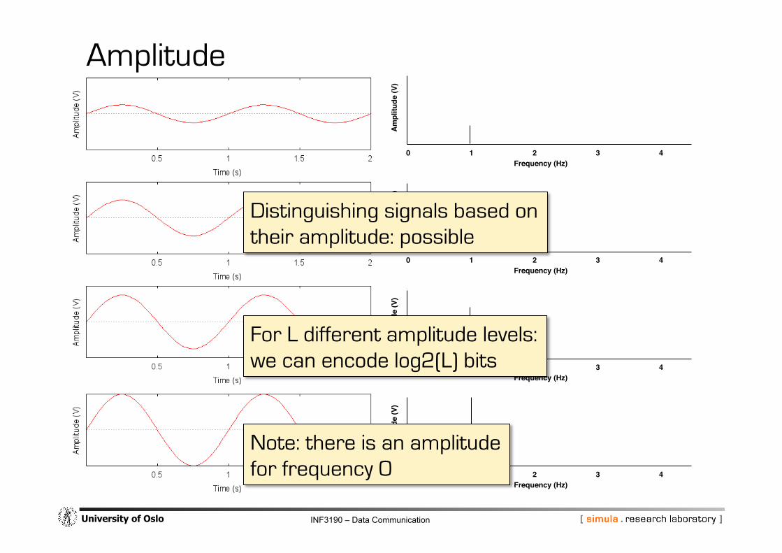
Amplitude
1! 2! 3! 4!0!
Am
plitu
de (V
)!
Frequency (Hz)!
1! 2! 3! 4!0!
Am
plitu
de (V
)!
Frequency (Hz)!
1! 2! 3! 4!0!
Am
plitu
de (V
)!
Frequency (Hz)!
1! 2! 3! 4!0!
Am
plitu
de (V
)!
Frequency (Hz)!
INF3190 – Data Communication University of Oslo
Amplitude
1! 2! 3! 4!0!
Am
plitu
de (V
)!
Frequency (Hz)!
1! 2! 3! 4!0!
Am
plitu
de (V
)!
Frequency (Hz)!
1! 2! 3! 4!0!
Am
plitu
de (V
)!
Frequency (Hz)!
1! 2! 3! 4!0!
Am
plitu
de (V
)!
Frequency (Hz)!
Distinguishing signals based on their amplitude: possible
For L different amplitude levels: we can encode log2(L) bits
Note: there is an amplitude for frequency 0

INF3190 – Data Communication University of Oslo
Phases
1! 2! 3! 4!0!
Am
plitu
de (V
)!
Frequency (Hz)!
1! 2! 3! 4!0!
Am
plitu
de (V
)!Frequency (Hz)!
1! 2! 3! 4!0!
Am
plitu
de (V
)!
Frequency (Hz)!
1! 2! 3! 4!0!
Am
plitu
de (V
)!
Frequency (Hz)!
0°
90°
180°
270°
Phase: position of the waveform relative to time 0

INF3190 – Data Communication University of Oslo
Phases
1! 2! 3! 4!0!
Am
plitu
de (V
)!
Frequency (Hz)!
1! 2! 3! 4!0!
Am
plitu
de (V
)!Frequency (Hz)!
1! 2! 3! 4!0!
Am
plitu
de (V
)!
Frequency (Hz)!
1! 2! 3! 4!0!
Am
plitu
de (V
)!
Frequency (Hz)!
0°
90°
180°
270°
Distinguishing signals based on their phase: possible
Change the phase in transmission to indicate a desired level Granularity depends on ability to detect the changes

INF3190 – Data Communication University of Oslo
Phases
1! 2! 3! 4!0!
Am
plitu
de (V
)!
Frequency (Hz)!
1! 2! 3! 4!0!
Am
plitu
de (V
)!Frequency (Hz)!
1! 2! 3! 4!0!
Am
plitu
de (V
)!
Frequency (Hz)!
1! 2! 3! 4!0!
Am
plitu
de (V
)!
Frequency (Hz)!
0°
90°
180°
270°
Where do we put the phase in the Fourier series decomposition?
SA, f (t) = A× sin(2π ft)SA, f (t +φ) = A× sin(2π ft +φ) φ =12π
φ = π
φ = 0
φ =32π

INF3190 – Data Communication University of Oslo
Phases of frequency 0
1! 2! 3! 4!0!
Am
plitu
de (V
)!
Frequency (Hz)!
1! 2! 3! 4!0!
Am
plitu
de (V
)!Frequency (Hz)!
1! 2! 3! 4!0!
Am
plitu
de (V
)!
Frequency (Hz)!
1! 2! 3! 4!0!
Am
plitu
de (V
)!
Frequency (Hz)!
0°
90°
180°
270°

INF3190 – Data Communication University of Oslo
The distance in meters (milli,micro,nano) between identical position of the wave (e.g.: peak amplitude) after one period (1/frequency).
Wavelength
wavelength
λ: wavelength (in meter)
where
v: speed of a wave in a medium (meter/second)
f: frequency (1/second)
λ =vf

INF3190 – Data Communication University of Oslo
The distance in meters (milli,micro,nano) between identical position of the wave (e.g.: peak amplitude) after one period (1/frequency).
Wavelength
λ: wavelength (in meter)
where
v: speed of a wave in a medium (meter/second)
f: frequency (1/second)
λ =vf
v for light in vacuum:
299 792 458 m/s
f for red light:
400–484 THz (1012Hz)
λ of red light in vacuum: 619-749 nm (10-9m)
INF3190 – Data Communication University of Oslo
Sender manipulates
§ frequency,
§ amplitude and
§ phase
directly to encode different signals.
Receivers transform back to information
§ derive their Fourier series parameters A and f at the receiving end
§ derive Φ from a known time base
Analog information coding
INF3190 – Data Communication University of Oslo
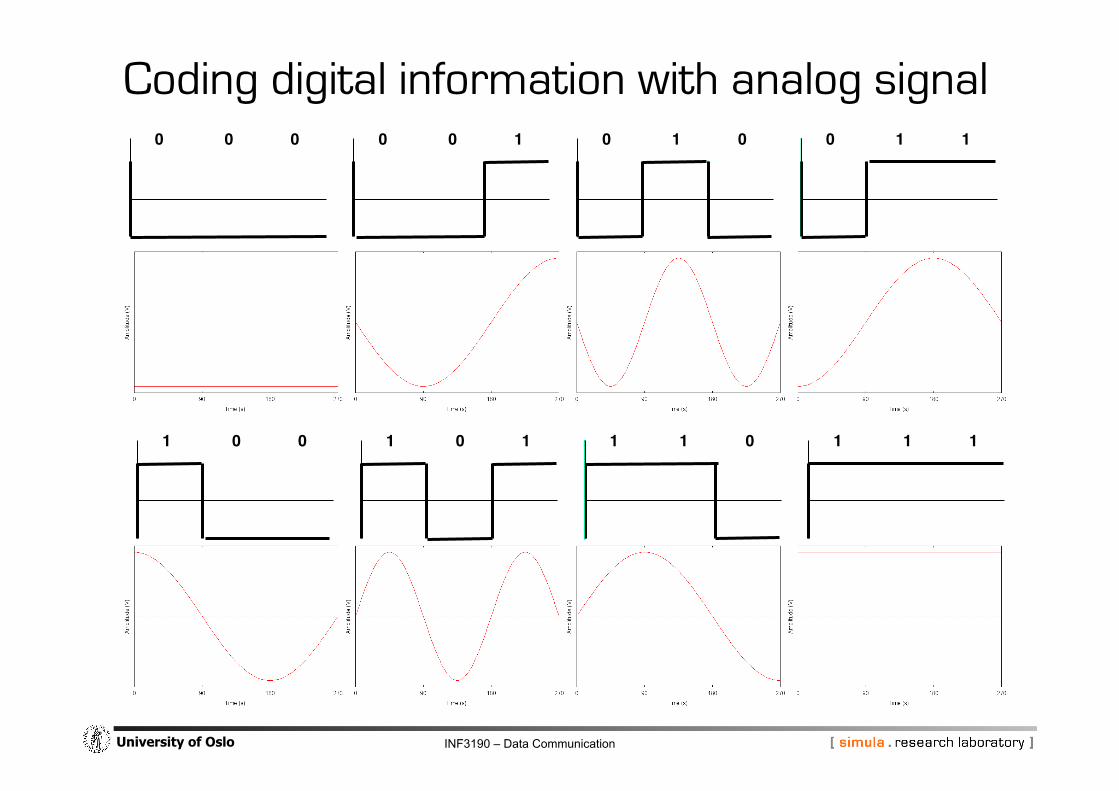
Coding digital information with analog signal 0! 1! 1!0! 0! 1! 0! 1! 0!0! 0! 0!
1! 1! 1!1! 0! 1! 1! 1! 0!1! 0! 0!

INF3190 – Data Communication University of Oslo
Data rate vs. signaling rate Signaling rate:
number of times per time unit (second) the signal parameter may change vS, measured in bauds (1/s), symbols/second
Data rate:
number of bits transmitted per time unit (second) vB, measured in bits per second (bit/s)
How many bits per symbol, i.e. vS ↔ vB: 1. binary signal: vB = vS 2. synchronization, clock, redundancy part of encoding: vB < vS 3. one symbol carries several bits (eg.: 00, 01, 10, 11): vB > vS
• for symbol with n values: vB = vS ld (n) • common: n = 2 (binary/bit), 3 (ternary), 4 (quarternary/DIBIT)
8 (octonary/TRIBIT), 10 (denary)

INF3190 – Data Communication University of Oslo
BAUD RATE measure of number of symbols (characters) transmitted per unit of time § signal speed, number of signal changes per
second: changes in amplitude, frequency, phase
§ each symbol normally consist of a number of bits § so the baud rate will only be the same as the bit
rate when there is one bit per symbol
Bit Rate and Baud Rate
BIT RATE number of bits transferred per second (bps) § bit rate may be higher than baud rate
("signal speed") § because one signal value may transfer
several bits § e.g. above same baud rate, different bit
rate (if x has have same dimension)
two bits per sample 00->00, 01->01 10->10, 11->11
three bits per sample 00->000, 01->001, 02->010 10->011, 11->100, 12->101 20->110, 21->111, 22-> ?

INF3190 – Data Communication University of Oslo
Nyquist’s theorem
0!A
mpl
itude
(V)!
f! 3f! 5f!
Maximum data rate of a channel For a noiseless channel (and perfect sampling), Nyquist has defined the theoretical maximum bit rate.
C = 2 * B* log2 L bit/second
2: upper and lower peak B: bandwidth L: number of levels

INF3190 – Data Communication University of Oslo
Composite signal
1! 2! 3! 4!0!
Am
plitu
de (V
)!
1! 2! 3! 4!0!
Am
plitu
de (V
)!1! 2! 3! 4!0!
Am
plitu
de (V
)!
1! 2! 3! 4!0!
Am
plitu
de (V
)!
Any composite signal is a combination of simple waves with different frequencies, amplitudes and phases.
If the composite signal is periodic, the decomposition gives a series of signals with discrete frequencies
If the composite signal is non-periodic, the decomposition gives a combination of waves with continuous frequencies

INF3190 – Data Communication University of Oslo
Composite signal
1! 2! 3! 4!0!
Am
plitu
de (V
)!
1! 2! 3! 4!0!
Am
plitu
de (V
)!
1! 2! 3! 4!0!
Am
plitu
de (V
)!
1! 2! 3! 4!0!
Am
plitu
de (V
)!
INF3190 – Data Communication University of Oslo
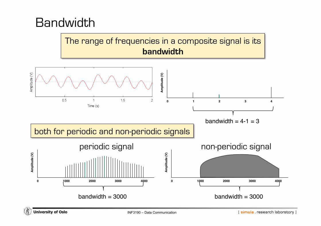
Bandwidth
1! 2! 3! 4!0!
Am
plitu
de (V
)!
The range of frequencies in a composite signal is its bandwidth
bandwidth = 4-1 = 3!
1000! 2000! 3000! 4000!0!
Am
plitu
de (V
)!
1000! 2000! 3000! 4000!0!
Am
plitu
de (V
)!
bandwidth = 3000! bandwidth = 3000!
periodic signal non-periodic signal
both for periodic and non-periodic signals

INF3190 – Data Communication University of Oslo
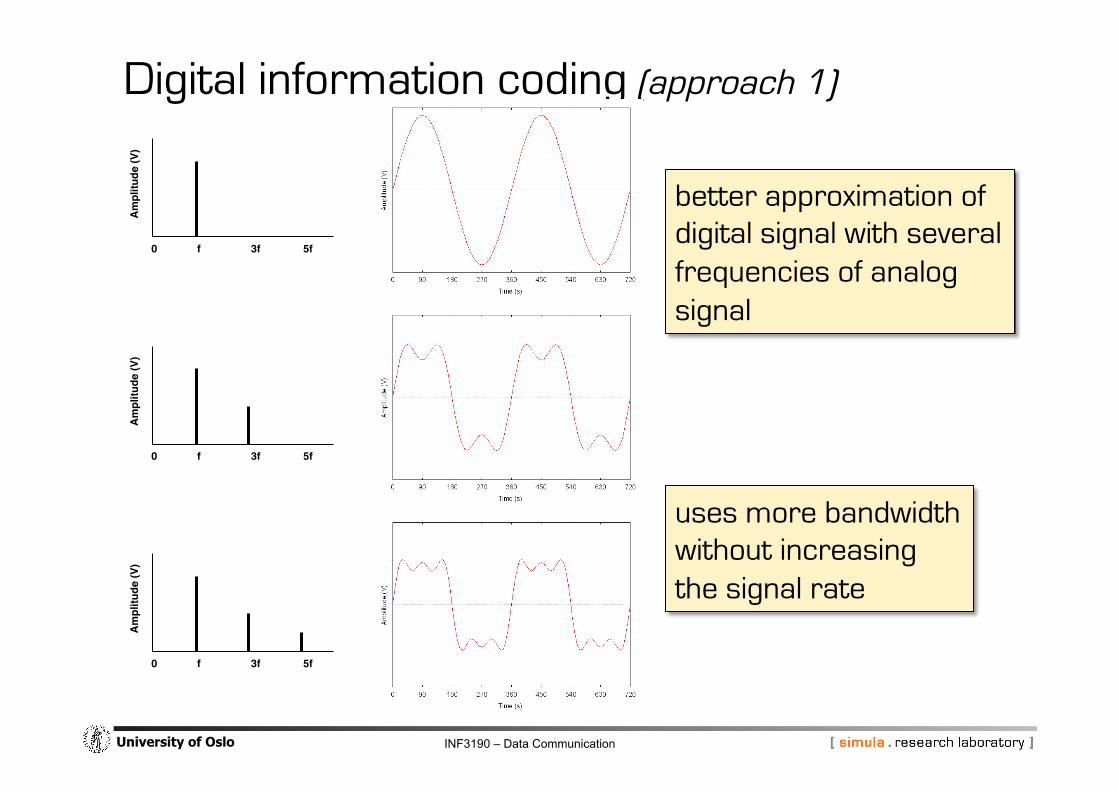
Indirect transmission of digital signals
§ approximate signaling flanks by composition of harmonic frequencies and amplitudes
§ allows to restrict between upper and lower frequencies
§ used bandwidth (max frequency – min frequency)
§ “can be restricted within a band”
Digital information coding (approach 1)
INF3190 – Data Communication University of Oslo
Digital information coding (approach 1)
0!
Am
plitu
de (V
)!
f! 3f! 5f!
0!
Am
plitu
de (V
)!
f! 3f! 5f!
0!
Am
plitu
de (V
)!
f! 3f! 5f!
better approximation of digital signal with several frequencies of analog signal
uses more bandwidth without increasing the signal rate

INF3190 – Data Communication University of Oslo
Direct transmission of digital signals
§ presence of absence of voltage indicates bits 1 and 0
§ is received as a distorted, composite signal
§ read voltage (amplitude) directly
§ separate time base
§ ignore frequency and phase − and there potential for carrying information
Digital information coding (approach 2)

INF3190 – Data Communication University of Oslo
Digital information coding (approach 2)
periodic digital signal
t! 2t! 3t! 4t!0!
Am
plitu
de (V
)!
0!
Am
plitu
de (V
)!
f! 3f! 5f! 7f!
...
it is a composite signal its bandwidth is infinite
t! 2t! 3t! 4t!0!
Am
plitu
de (V
)!
0!
Am
plitu
de (V
)!
f! 3f! 5f! 7f!
non-periodic digital signal (e.g. 1 one-bit )
...
infinite bandwidth continuous frequencies

INF3190 – Data Communication University of Oslo
Digital information coding (approach 2)
t! 2t! 3t! 4t!0!
Am
plitu
de (V
)!
0!
Am
plitu
de (V
)!
f! 3f! 5f! 7f!
...
t! 2t! 3t! 4t!0!
Am
plitu
de (V
)!
0!A
mpl
itude
(V)!
f! 3f! 5f! 7f!
limited bandwidth channel
input signal
output signal better with very wide bandwidth channel

INF3190 – Data Communication University of Oslo
Bandwidth
Baseband
1000! 2000! 3000! 4000!0!
Am
plitu
de (V
)!
Passband
1000! 2000! 3000! 4000!0!
Am
plitu
de (V
)!
Includes frequencies very close to 0
Typical for electrical signals over cables
Can be used with approaches 1 and 2
A range of frequencies that is isolated for processing through a bandpass filter
Necessary for wireless channels Typical for optical cables
Can be used with approach 1

INF3190 – Data Communication University of Oslo
Shannon’s Capacity Most often, we have noise on a channel

INF3190 – Data Communication University of Oslo
Shannon’s Capacity But most often, we have noise on a channel
possible reasons • thermal noise, free electrons • impulse noise, e.g. from power lines, lightning • induced noise, e.g. from electric motors • crosstalk from other channels (remember
that our input signal uses infinite bandwidth!)

INF3190 – Data Communication University of Oslo
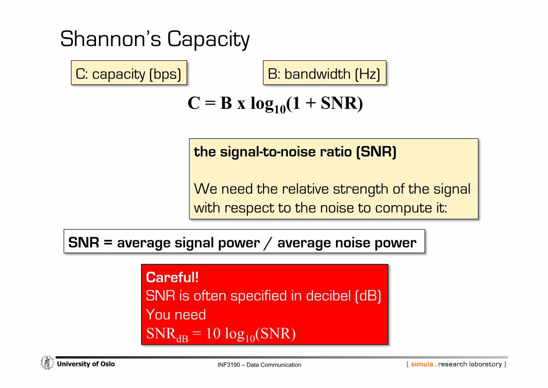
We cannot avoid bit errors from noise
But Shannon has introduced a formula that determines the highest theoretical data rate for a noise channel
C = B x log10(1 + SNR)
Shannon’s Capacity
the signal-to-noise ratio (SNR)
C: capacity (bps) B: bandwidth (Hz)
INF3190 – Data Communication University of Oslo
C = B x log10(1 + SNR)
Shannon’s Capacity
the signal-to-noise ratio (SNR) We need the relative strength of the signal with respect to the noise to compute it:
C: capacity (bps) B: bandwidth (Hz)
Careful! SNR is often specified in decibel (dB) You need SNRdB = 10 log10(SNR)
SNR = average signal power / average noise power

INF3190 – Data Communication University of Oslo
Information coding
§ Binary Encoding
§ Non-return-to-zero, inverted
§ Manchester Encoding
§ Differential Manchester Encoding
Multiplexing Techniques
§ Frequency Multiplexing
§ Time Division Multiplexing
§ Multiplexer and Concentrator
Part 2: Information coding

INF3190 – Data Communication University of Oslo
Digital Information – Digital Transmission Digital transmission § high bit rate § sender/receiver synchronization
− common understanding of phase
− clock recovery
§ signal levels around 0V (lower power) − error protection
Coding techniques § binary encoding, non-return to zero-level (NRZ-L)
− 1: high level
− 0: low level
§ return to zero (RZ)
− 1: clock pulse (double frequency) during interval
− 0: low level
§ Non-return-to-zero, inverted
§ Manchester Encoding
§ Differential Manchester Encoding
§ ...

INF3190 – Data Communication University of Oslo
Binary encoding (NRZ, Non-return-to-zero): § "1": voltage on high
§ "0": voltage on low
i.e. + simple, cheap
+ good utilization of the bandwidth (1 bit per Baud)
- no "self-clocking" feature
Binary Encoding ©
Ralf S
teinmetz, Technische U
niversität Darm
stadt

INF3190 – Data Communication University of Oslo
Non-return-to-zero, inverted:
§ “1": change in the level
§ “0": no change in the level
USB uses opposite convention
§ change on 0, no change on 1
+ simple
+ 1 bit per Baud
− no “self-clocking”
− clock must be ensured by bit stuffing
Non-return-to-zero, inverted
1! 0! 0! 0! 0! 0!1! 1! 1! 1! 1!Bit stream!
Binary encoding!(NRZ)!
NRZI!

INF3190 – Data Communication University of Oslo
Bit interval is divided into two partial intervals: I1, I2
§ "1”: I1: high, I2: low
§ "0”: I1: low, I2: high
+ good "self-clocking" feature
− 0,5 bit per Baud
Application: 802.3 (CSMA/CD)
Manchester Encoding ©
Ralf S
teinmetz, Technische U
niversität Darm
stadt

INF3190 – Data Communication University of Oslo
Differential Manchester Encoding: § bit interval divided into two partial
intervals:
− "1": no change in the level at the beginning of the interval
− "0": change in the level
+ good "self-clocking" feature + low susceptibility to noise because only
the signal’s polarity is recorded. Absolute values are irrelevant.
− 0,5 bit per Baud − complex
Differential Manchester Encoding ©
Ralf S
teinmetz, Technische U
niversität Darm
stadt

INF3190 – Data Communication University of Oslo
© R
alf Steinm
etz, Technische Universität D
armstadt
Multiplexing Techniques Cost for implementing and maintaining either a narrowband or a wideband cable are almost the same
Multiplexing many conversations onto one channel
Two types § FDM
(Frequency Division Multiplexing)
§ TDM (Time Division Multiplexing)

INF3190 – Data Communication University of Oslo
Principle § frequency band is split between the users § each user is allocated one frequency band
Application § example: multiplexing of voice telephone channels: phone, cable-tv
§ filters limit voice channel to 3 000 Hz bandwidth § each voice channel receives 4 000 Hz bandwidth
− 3 000 Hz voice channel − 2 x 500 Hz gap (guard band)
Frequency Multiplexing ©
Ralf S
teinmetz, Technische U
niversität Darm
stadt

INF3190 – Data Communication University of Oslo
Principle § user receives a time slot
§ during this time slot he has the full bandwidth
Application § multiplexing of end systems, but also
§ in transmission systems
Time Division Multiplexing ©
Ralf S
teinmetz, Technische U
niversität Darm
stadt

INF3190 – Data Communication University of Oslo
MULTIPLEXER § INPUT from various links in predefined order
§ OUTPUT at one single link in the same order
Multiplexer and Concentrator ©
Ralf S
teinmetz, Technische U
niversität Darm
stadt

INF3190 – Data Communication University of Oslo
Multiplexer and Concentrator
Concentrator § INPUT from several links § OUTPUT at one single link § no fixed slot allocation,
instead sending of (station addresses, data)
PROBLEM: All stations use maximum speed for sending § "Solution": internal buffers
Multiplexer Concentrator
© R
alf Steinm
etz, Technische Universität D
armstadt