Embed Size (px)
Citation preview

- 0 -I.View Installation & Calibration Manual
Software Version:WS10_11 /_14
I.View Manual for Wheel Loaderinstallation and calibration manual
Codice Manuale | Manual Code
000147-IVWPAL.ica.EN.03-DFE

- 1 -I.View Installation & Calibration Manual
�����
� ���������AB���CA�DD�A�E�
F �������AC����E��E���A�EC�A�E����
� �E�A�ED�E�
� ����A�E��E�
� �B��DDE����� �������CA�� !�
�EC�A�E���� �C��FC��CE�E�AB��B�CC�C
" �B��DDE����� �������CA�� !��EC�A�E���� �C��"C��CE�E�AB������EE�
# �B��DDE����� �������CA�� !��EC�A�E���� ��E����A$ C��CE�CE�AB������EE�
% �B��DDE����� �������CA�� !�
�EC�A�E���� ��E����A$ C��CE�CE�AB������EE�
&! �B��DDE����� �������CA�� !�
�EC�A�E���� ��E����A$ C��CE�CE�AB������EE�
&& �B��DDE����� �������CA�� !��EC�A�E���� ��E����A$ C��CE�CE�AB������EE�
&� 'E�(D�'A� �������CA�� !��EC�A�E���� ��E����A$ C��CE�CE�AB������EE�
&F ���CC���A���C�����C
&� ���CC���A���C�����C
&� ���CC���A���C�����C��)*�+�,-./0-12,/3�.3/���2,1/��*�+/
&� '�����D�CE����B���C
&" (�$����A�'���A�E�
&# C$CA�������ECA�� ����C
&% ����CCAE��D����A�E� ����C
�! ����B�����D����A�E�
�& ����B�����D����A�E�������A�E
�� ����B�����D����A�E�
���D���D����A�E� � �������CA�� !�
�F ����B�����D����A�E�
���D���D����A�E� � �������CA�� !�
�� ����B�����D����A�E�
���CC�����D����A�E�
�� ����B�����D����A�E�
���CC�����D����A�E� 4 ���A$���(�A
�� ����B�����D����A�E����CC�����D����A�E� 4 ���CC���A��D�
�" ����B�����D����A�E�
���CC�����D����A�E� 4 DE�������(�A
�# ����B�����D����A�E�
(�E��DE��
�% ����B�����D����A�E�
�������$��D���A�E�
F! ������A��C
F& ������A��C
����B���
F� �E�'�����A�E�C$CA��C�D��A�E�
FF �E�'�����A�E�DE��D�5�A�E�
F� �E�'�����A�E�
�B�����C�������C����A�'���
F� �E�'�����A�E�
C$CA��C�D��A�E�
F� ����
F" #! �� ��!!�!6�������CA��!�7C$CA��D�$E�A
F# #! �� ��!!�!6�������CA��!�7C$CA��D�$E�A
F% #! �� ��!!�!6�������CA��!�7C$CA��D�$E�A
�! #! �� ��!!�!6�������CA��!�7C$CA��D�$E�A
�& #! �� ��!!�!6�������CA��!�7C$CA��D�$E�A
�� #! �� ��!!�!6�������CA��!�7C$CA��D�$E�A

- 2 -I.View Installation & Calibration Manual
The following equipment is needed for easy installation of the system.
• Electric or explosive welder• Normal mechanical and electrical tools• Set of adjustable spanners• Set of screwdrivers• Lapping machine• Tester
Take the system out of its packaging and make sure that the individual parts have notbeen damaged during transport.Using the system composition (end of this manual) and the transport document makesure that all the parts needed to install the system on your machine are available.
IMPORTANT INFORMATION ON SAFETY FOR WORKING WITH MOBILE MAC HINES
Protective equipment
Always wear protective goggles as required by the working conditions when welding orusing the lapping machine.Do not wear baggy clothes and jewellery which could be caught in the machine.
Repairs
Disconnect the battery and discharge any electric charges before beginning work on themachine.If possible move the machine inside a shed or to a surface with hard and clean ground.
������ABCDE�C�AFD��D��A

- 3 -I.View Installation & Calibration Manual
Wheel Loader
CAHSSIS with Chassis Angular
Sensor ID63
BUCKET
CHASSIS
FORK
UPRIGHT
Fork Lift
Control Box
PRESSURE TRANSDUCERS
BOOM withBoom Angular Sensor ID67
Control Box
Proximity Sensors
PRESSURE TRANSDUCERS
A��C��DFC���C�����A�ADC��F�D��A�AB
- 4 -I.View Installation & Calibration Manual
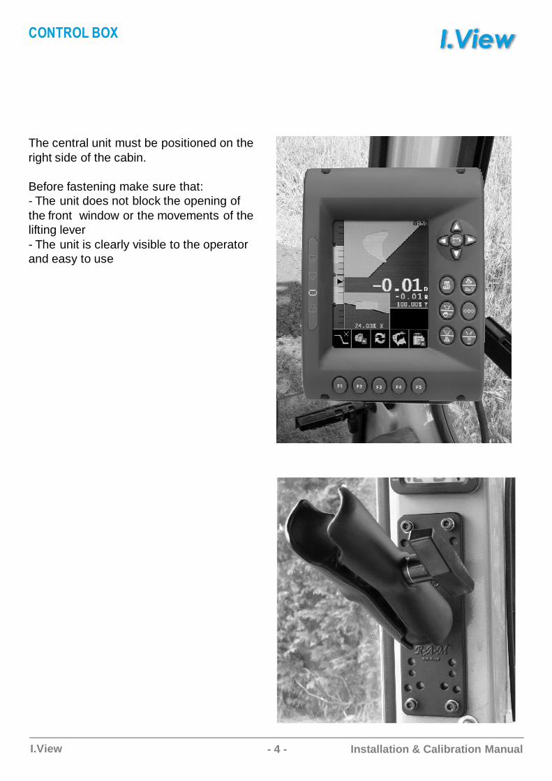
The central unit must be positioned on the right side of the cabin.
Before fastening make sure that: - The unit does not block the opening of the front window or the movements of the lifting lever- The unit is clearly visible to the operator and easy to use
��AD���C���

- 5 -I.View Installation & Calibration Manual
The junction box is a wiring hub that groups all the machine cables, from battery and sensors.The junction box can be positioned in the battery compartment, back to the seat or below thecabin.Keep it away from water or dirty (protect unused connectors).
Example: Positioning under the cabin
��A�D��AC���
POWER SUPPLY46.41.1601XX
ANGLE SENSORS46.41.2201XX
CE
C1
A B
D
A
C6
F B
B C
C3
A
C
B
D E
F
DF E
C5
J
B
C
D
HAK
E
G
F
G
C2BAH
K J C
C4A D
LOW CHAMBER PRESSURE TRANSDUCER46.41.0800XX
PROXIMITY46.41.1801XX
HIGH CHAMBER PRESSURE TRANSDUCER46.41.1701XX
- 6 -I.View Installation & Calibration Manual
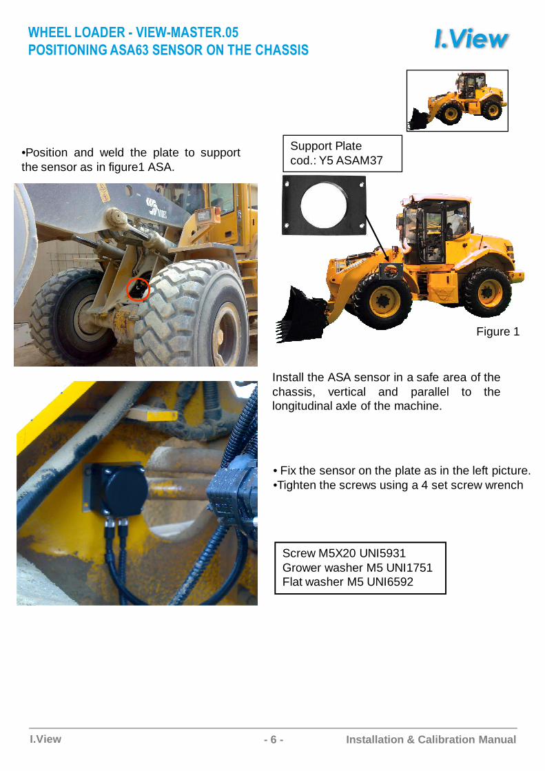
•Position and weld the plate to supportthe sensor as in figure1 ASA.
• Fix the sensor on the plate as in the left picture.•Tighten the screws using a 4 set screw wrench
Figure 1
Install the ASA sensor in a safe area of thechassis, vertical and parallel to thelongitudinal axle of the machine.
Support Platecod.: Y5 ASAM37
Screw M5X20 UNI5931Grower washer M5 UNI1751 Flat washer M5 UNI6592
�E���C�����C� ������FD�����
��F�D��A�ABCF !CF�AF��C�ACDE�C�EFF�F
- 7 -I.View Installation & Calibration Manual
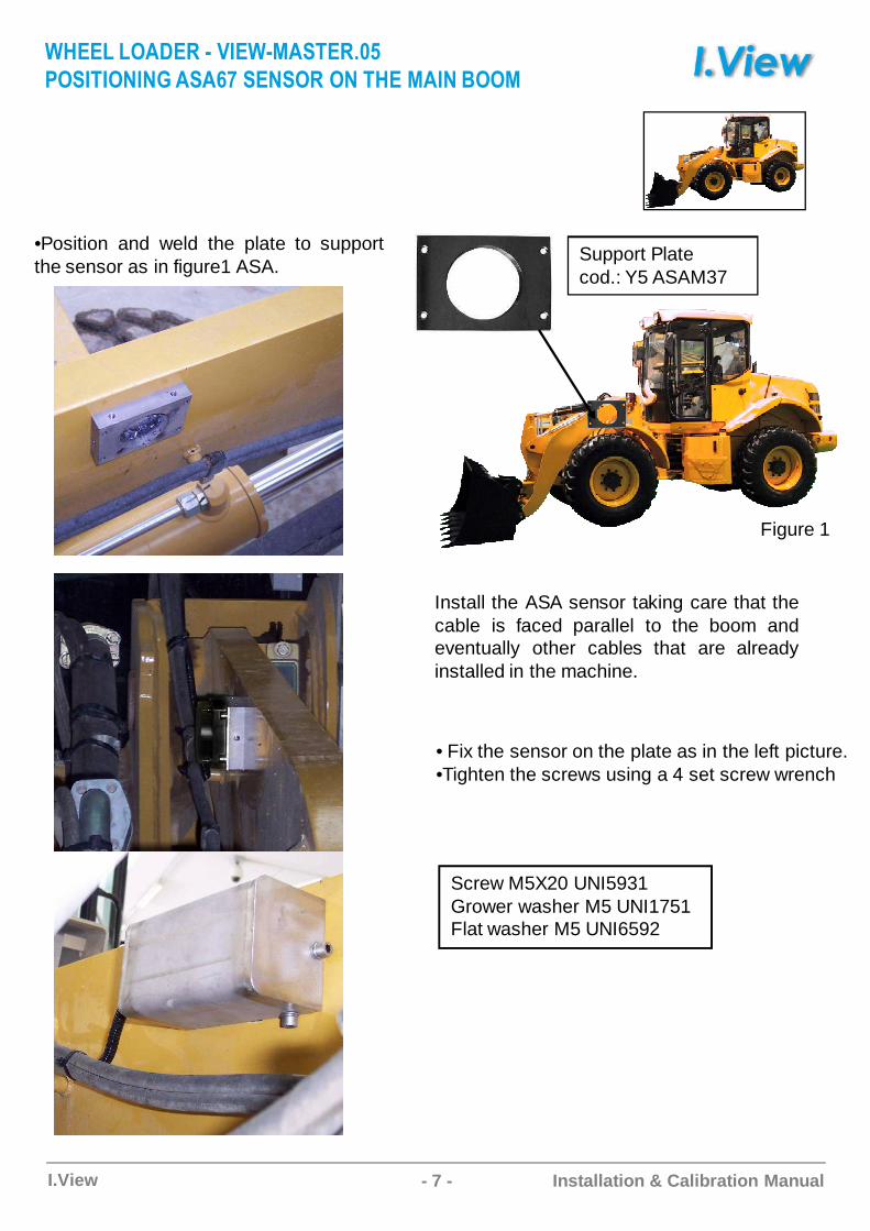
•Position and weld the plate to supportthe sensor as in figure1 ASA.
• Fix the sensor on the plate as in the left picture.•Tighten the screws using a 4 set screw wrench
Figure 1
Install the ASA sensor taking care that thecable is faced parallel to the boom andeventually other cables that are alreadyinstalled in the machine.
Support Platecod.: Y5 ASAM37
Screw M5X20 UNI5931Grower washer M5 UNI1751 Flat washer M5 UNI6592
�E���C�����C� ������FD�����
��F�D��A�ABCF "CF�AF��C�ACDE�C��AC����

- 8 -I.View Installation & Calibration Manual
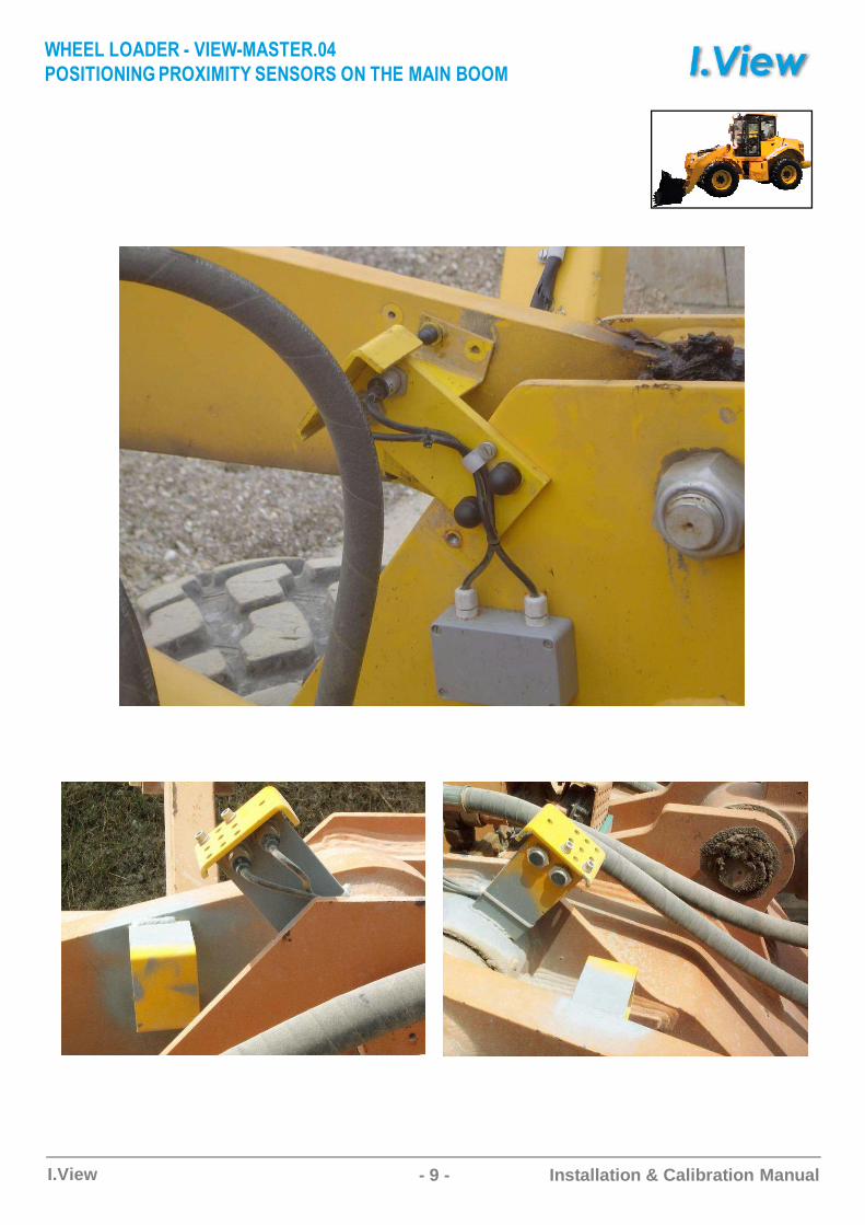
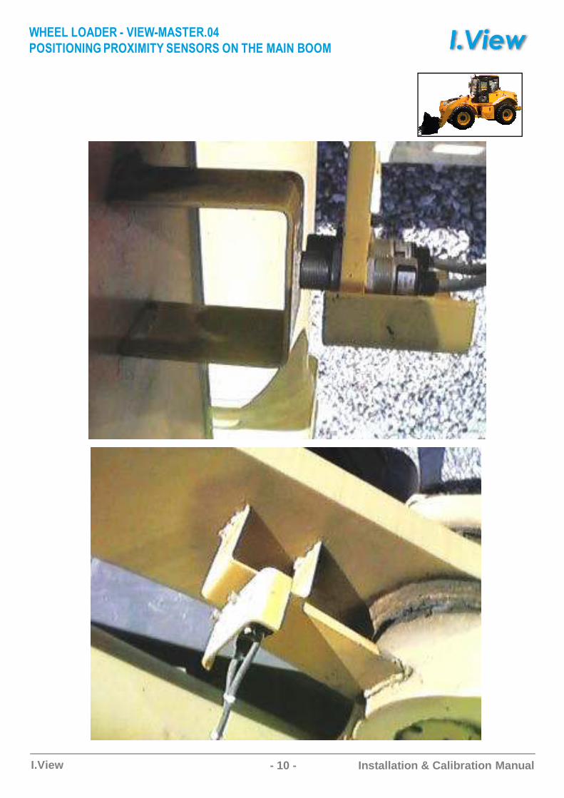
Positioning the proximity sensors is extremely important for the weighing accuracy during the lifting stage. Proximity have to be installed taking care that the lifting reference notch activates the first proximity switch, and that it remains active even when the second has been activated. If the weighing system is running properly, the acoustic indicator will go off after the second proximity has been reached. This means a measurement has been made. Vice-versa, when the vehicle arm is coming down, it must first activate the second proximity, and then the first. In this way weighing takes place only during lifting and not lowering.
In order to have the system properly operate, it is recommended to enable the weighing phase when the points A and B are aligned as in the picture here below.
A B
�E���C�����C� ������FD����#
��F�D��A�ABC�������D$CF�AF��FC�ACDE�C��AC����
- 9 -I.View Installation & Calibration Manual
�E���C�����C� ������FD����#
��F�D��A�ABC�������D$CF�AF��FC�ACDE�C��AC����
- 10 -I.View Installation & Calibration Manual
�E���C�����C� ������FD����#
��F�D��A�ABC�������D$CF�AF��FC�ACDE�C��AC����

- 11 -I.View Installation & Calibration Manual
The box is IP65 waterproof, and has been designed to protect the electrical connection between proximity sensors and the cable connected to the junction box.
We would advise you to position the box as near as possible to the proximity brackets,so that connections can be more easily made.
�E���C�����C� ������FD����#
��F�D��A�ABC�������D$CF�AF��FC�ACDE�C��AC����

- 12 -I.View Installation & Calibration Manual
40/50 cm
In a fork lift the proximity distance has to be about 20 cm due the highspeed of the fork rising.From ground, the start weigh point should be at least 40 cm.From the proximity “head” and the moving part installed on themachine, the max distance is 5 mm, so try to keep 2-3 mm of airbetween the proximity and the metal when is activated.
%��&C��%DC� ������FD����
��F�D��A�ABC�������D$CF�AF��FC�ACDE�C��AC����
- 13 -I.View Installation & Calibration Manual
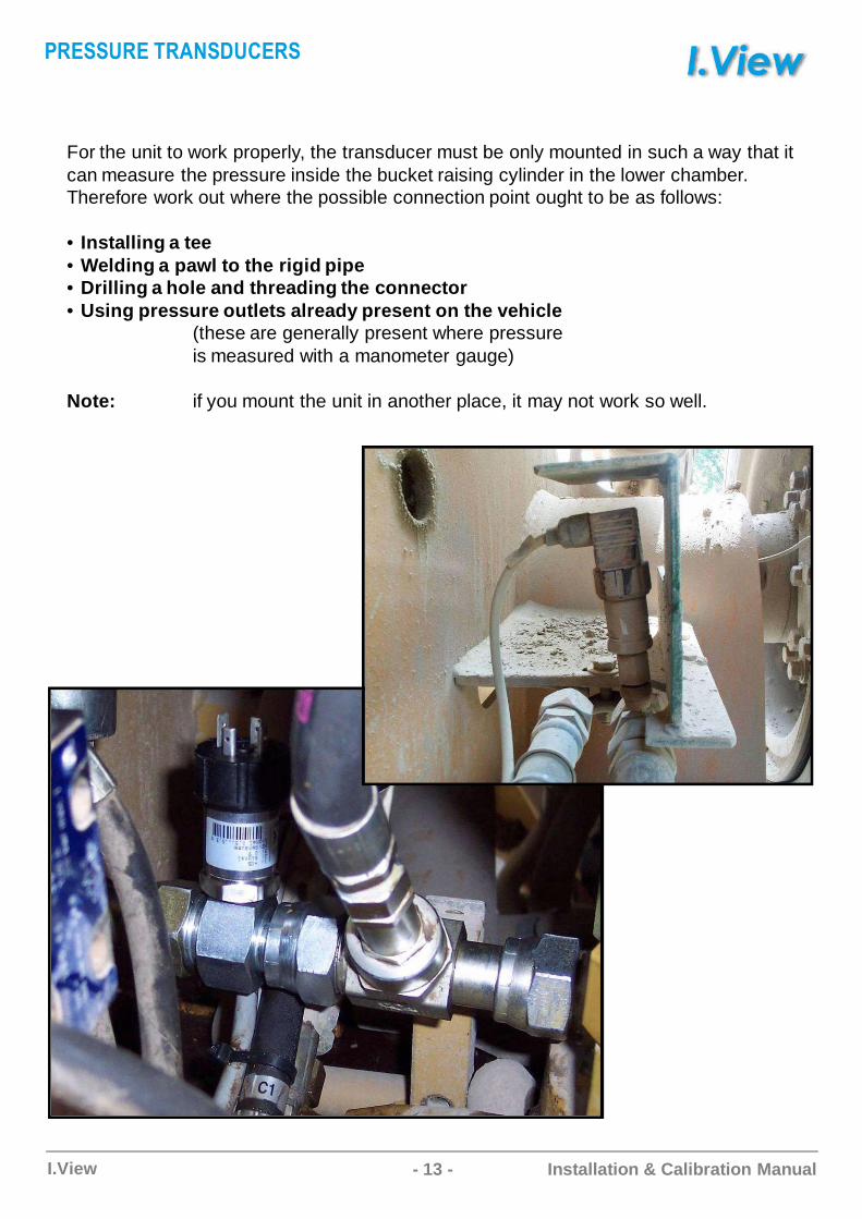
For the unit to work properly, the transducer must be only mounted in such a way that it can measure the pressure inside the bucket raising cylinder in the lower chamber. Therefore work out where the possible connection point ought to be as follows:
• Installing a tee• Welding a pawl to the rigid pipe• Drilling a hole and threading the connector• Using pressure outlets already present on the vehicle
(these are generally present where pressureis measured with a manometer gauge)
Note: if you mount the unit in another place, it may not work so well.
���FF���CD�AF�����F
- 14 -I.View Installation & Calibration Manual
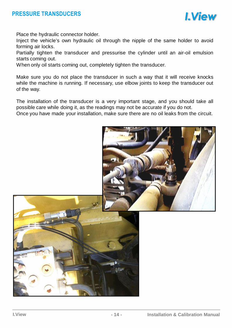
Place the hydraulic connector holder.Inject the vehicle’s own hydraulic oil through the nipple of the same holder to avoidforming air locks.Partially tighten the transducer and pressurise the cylinder until an air-oil emulsionstarts coming out.When only oil starts coming out, completely tighten the transducer.
Make sure you do not place the transducer in such a way that it will receive knockswhile the machine is running. If necessary, use elbow joints to keep the transducer outof the way.
The installation of the transducer is a very important stage, and you should take allpossible care while doing it, as the readings may not be accurate if you do not.Once you have made your installation, make sure there are no oil leaks from the circuit.
���FF���CD�AF�����F
- 15 -I.View Installation & Calibration Manual
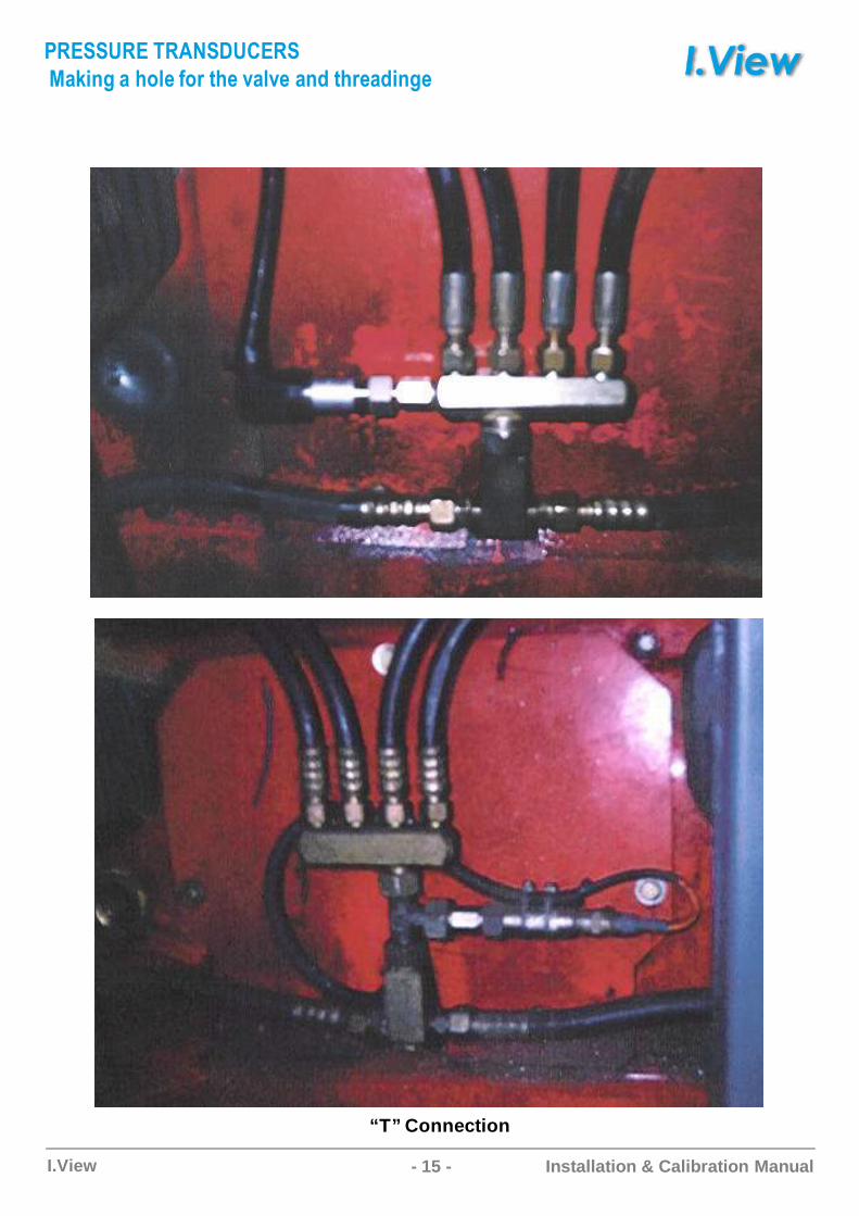
“T” Connection
���FF���CD�AF�����F
��'(�)C�C*+,�C-+.C/*�C0�,0�C���C/*.���(�)�
- 16 -I.View Installation & Calibration Manual
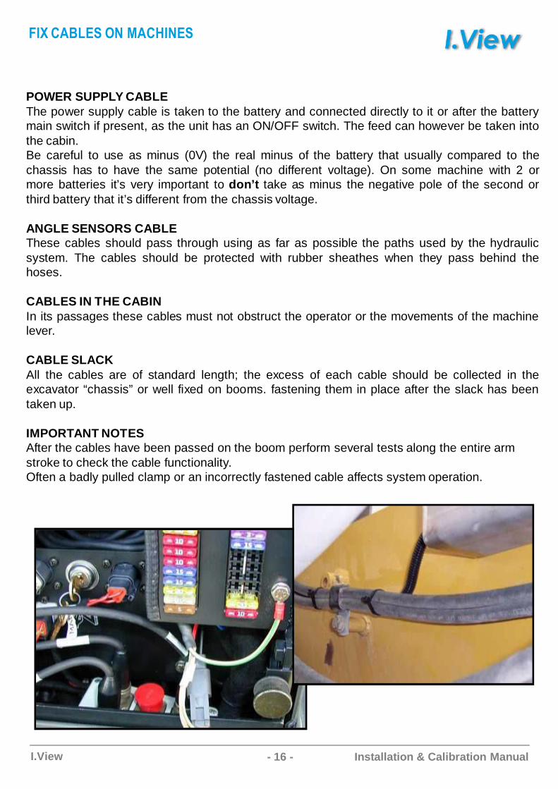
POWER SUPPLY CABLEThe power supply cable is taken to the battery and connected directly to it or after the batterymain switch if present, as the unit has an ON/OFF switch. The feed can however be taken intothe cabin.Be careful to use as minus (0V) the real minus of the battery that usually compared to thechassis has to have the same potential (no different voltage). On some machine with 2 ormore batteries it’s very important to don’t take as minus the negative pole of the second orthird battery that it’s different from the chassis voltage.
ANGLE SENSORS CABLEThese cables should pass through using as far as possible the paths used by the hydraulicsystem. The cables should be protected with rubber sheathes when they pass behind thehoses.
CABLES IN THE CABINIn its passages these cables must not obstruct the operator or the movements of the machinelever.
CABLE SLACKAll the cables are of standard length; the excess of each cable should be collected in theexcavator “chassis” or well fixed on booms. fastening them in place after the slack has beentaken up.
IMPORTANT NOTESAfter the cables have been passed on the boom perform several tests along the entire arm stroke to check the cable functionality. Often a badly pulled clamp or an incorrectly fastened cable affects system operation.
%��C����FC�AC��E�A�F
- 17 -I.View Installation & Calibration Manual
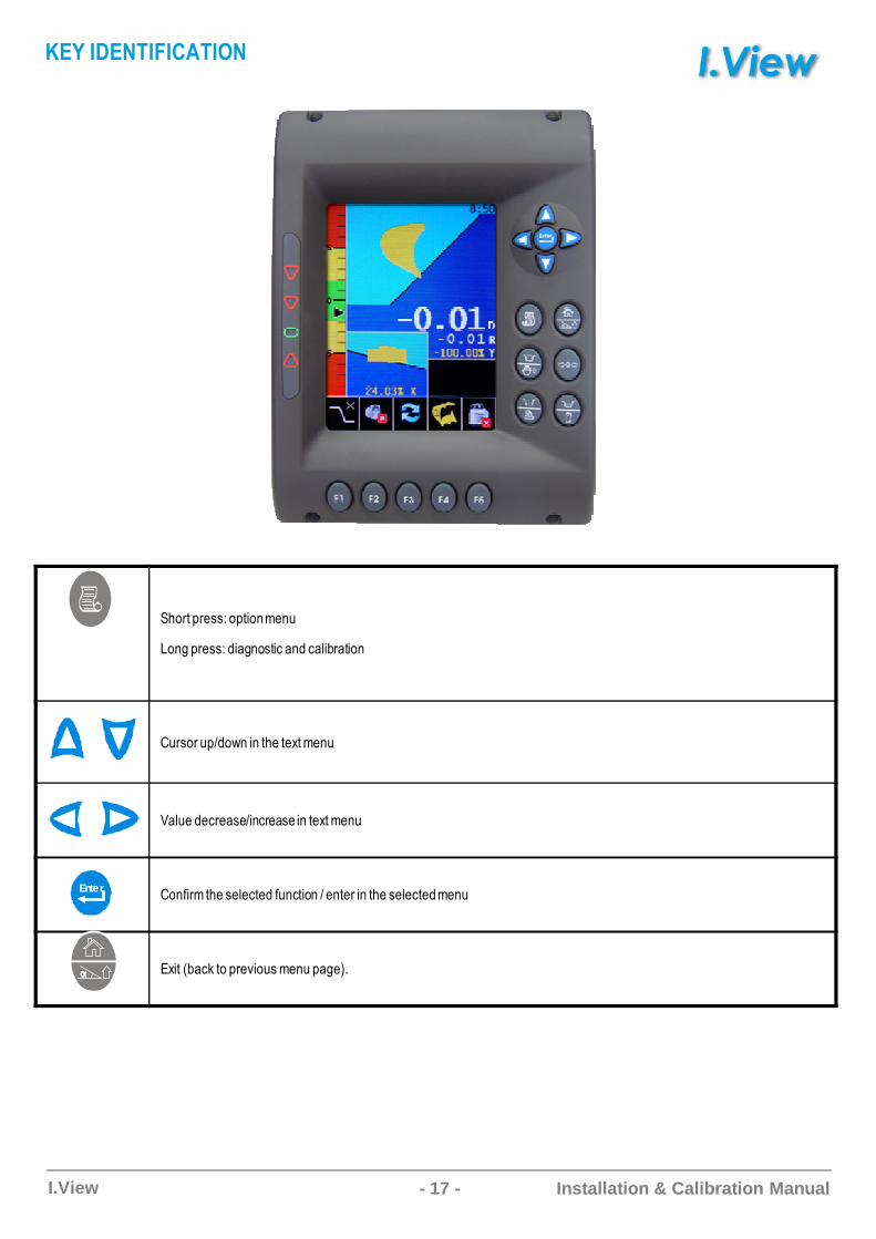
C,-1281/99:-82*-�;/�<
D-�+81/99:�*�+�-92*=���=�.*>1�2*-�
�<19-1<8?�-@�*�2,/2/A2;/�<
��.</�/=1/�9/?*�=1/�9/*�2/A2;/�<
�-�0*1;2,/9/./=2/�0<�=2*-�?/�2/1*�2,/9/./=2/�;/�<
�A*26>�=)2-81/3*-<9;/�<8�+/7
Enter
&�$C���AD�%��D��A
- 18 -I.View Installation & Calibration Manual
���������ABCDECFD
��B����B��BF���������E���B��������CDEE���B�������
�FD�B��E���C��������� �!�"#B$��������� �
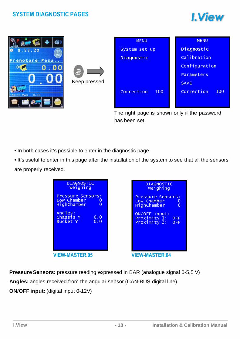
Pressure Sensors: pressure reading expressed in BAR (analogue signal 0-5,5 V)
Angles: angles received from the angular sensor (CAN-BUS digital line).
ON/OFF input: (digital input 0-12V)
• In both cases it’s possible to enter in the diagnostic page.
• It’s useful to enter in this page after the installation of the system to see that all the sensors
are properly received.
%&�'
�(�$B� �B$ �)
�C�DF��$C"�C�DF��$C"�C�DF��$C"�C�DF��$C"
���B"$C�F *��
%&�'
�C�DF��$C"�C�DF��$C"�C�DF��$C"�C�DF��$C"
��C���$C�F
�F+CD���$C�F
�����B$B��
��,&
���B"$C�F���*��
The right page is shown only if the passwordhas been set,
Keep pressed
F$FD��C��BA�FD��C�B�F
���������ABCDECFD
��B����B��BF���������E���B��������CDEE���B�������
��-�..�CF)�$����/C�C$(�*����..���/C�C$(�0����..
������FD����#������FD�����
- 19 -I.View Installation & Calibration Manual
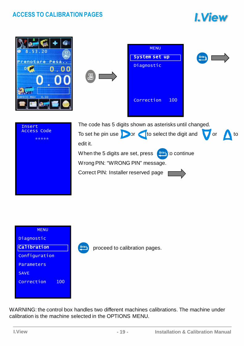
The code has 5 digits shown as asterisks until changed.
To set he pin use or to select the digit and or to
edit it.
When the 5 digits are set, press to continue
Wrong PIN: “WRONG PIN” message.
Correct PIN: Installer reserved page
Enter
�F�B�$�""B����1B
22222
proceed to calibration pages.Enter
%&�'
�C�DF��$C"
��C���$C�F��C���$C�F��C���$C�F��C���$C�F
�F+CD���$C�F
�����B$B��
��,&
���B"$C�F����*��
WARNING: the control box handles two different machines calibrations. The machine under calibration is the machine selected in the OPTIONS MENU.
%&�'
�(�$B��(�$B��(�$B��(�$B� �B$�B$�B$�B$ �)�)�)�)
�C�DF��$C"
���B"$C�F *��
Enter
���FFCD�C�����D��AC�B�F
- 20 -I.View Installation & Calibration Manual
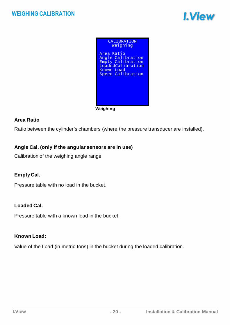
Area Ratio
Ratio between the cylinder’s chambers (where the pressure transducer are installed).
Angle Cal. (only if the angular sensors are in use)
Calibration of the weighing angle range.
Empty Cal.
Pressure table with no load in the bucket.
Loaded Cal.
Pressure table with a known load in the bucket.
Known Load:
Value of the Load (in metric tons) in the bucket during the loaded calibration.
���!3�����ABCDECFD
��B��3�$C��FD�B���C���$C�F&�)$(���C���$C�F���1B1��C���$C�F4F��F����1�)BB1���C���$C�F
Weighing
���BE�ABC�����D��A
- 21 -I.View Installation & Calibration Manual
Low Chamber
High Chamber
��B��3�$C�C�"��+B�BF"B������E���B��� ����CDEE���B��� ���
�
3�$C�5��������6��
�B$�7���B���F1)�B���&F$B�
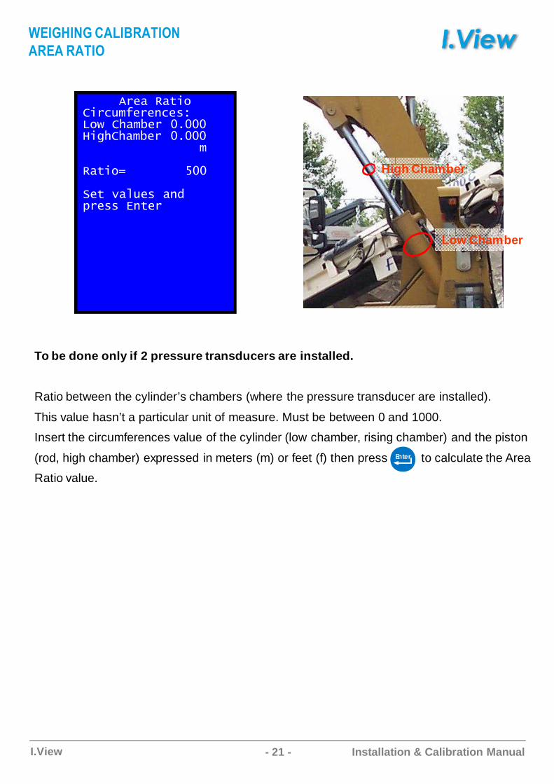
To be done only if 2 pressure transducers are insta lled.
Ratio between the cylinder’s chambers (where the pressure transducer are installed).
This value hasn’t a particular unit of measure. Must be between 0 and 1000.
Insert the circumferences value of the cylinder (low chamber, rising chamber) and the piston
(rod, high chamber) expressed in meters (m) or feet (f) then press to calculate the Area
Ratio value.
Enter
���BE�ABC�����D��A
��C�D��
- 22 -I.View Installation & Calibration Manual
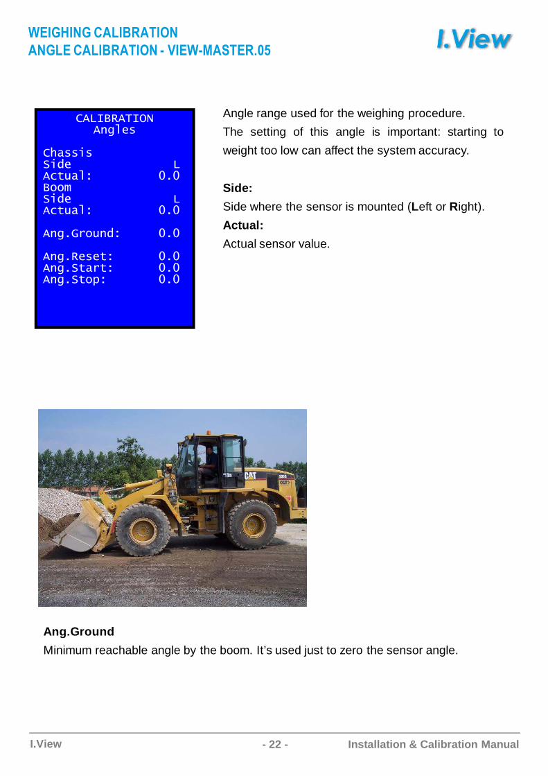
Angle range used for the weighing procedure.
The setting of this angle is important: starting to
weight too low can affect the system accuracy.
Side:
Side where the sensor is mounted (Left or Right).
Actual:
Actual sensor value.
���!3������FD�B�
E���C��C1B����������������"$�������������� �!����C1B����������������"$�������������� �
�FD ����F1������� �
�FD 3B�B$�������� ��FD �$��$�������� ��FD �$�)��������� �
Ang.Ground
Minimum reachable angle by the boom. It’s used just to zero the sensor angle.
���BE�ABC�����D��A
AB��C�����D��AC� ������FD�����
- 23 -I.View Installation & Calibration Manual
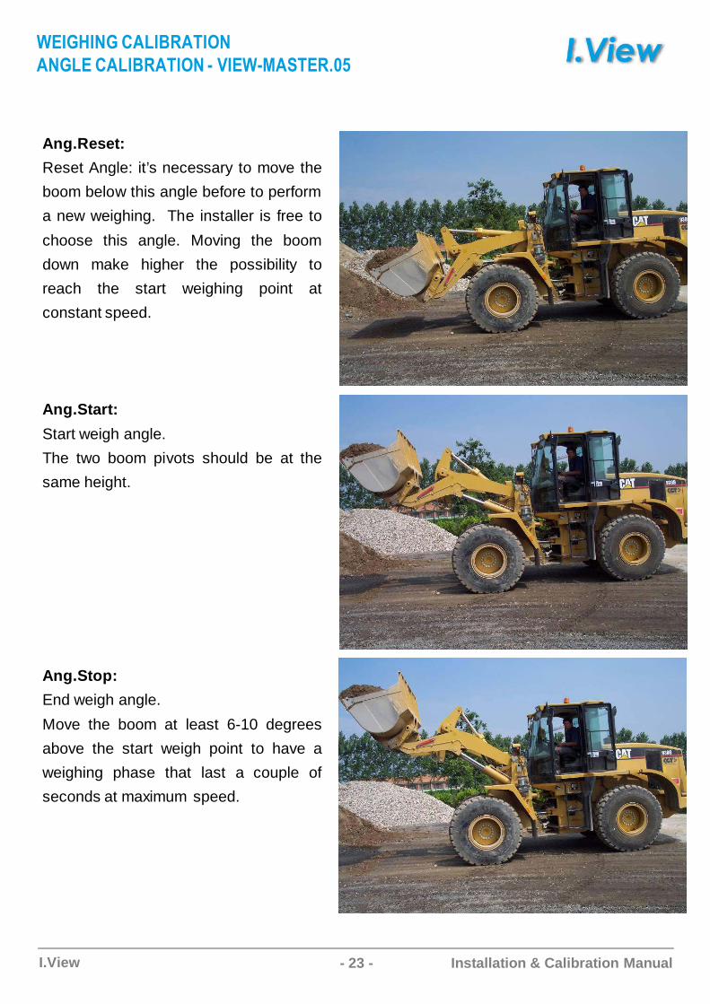
Ang.Reset:
Reset Angle: it’s necessary to move the
boom below this angle before to perform
a new weighing. The installer is free to
choose this angle. Moving the boom
down make higher the possibility to
reach the start weighing point at
constant speed.
Ang.Start:
Start weigh angle.
The two boom pivots should be at the
same height.
Ang.Stop:
End weigh angle.
Move the boom at least 6-10 degrees
above the start weigh point to have a
weighing phase that last a couple of
seconds at maximum speed.
���BE�ABC�����D��A
AB��C�����D��AC� ������FD�����
- 24 -I.View Installation & Calibration Manual
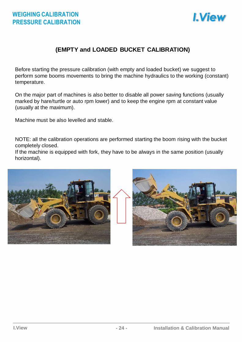
Before starting the pressure calibration (with empty and loaded bucket) we suggest to perform some booms movements to bring the machine hydraulics to the working (constant) temperature.
On the major part of machines is also better to disable all power saving functions (usually marked by hare/turtle or auto rpm lower) and to keep the engine rpm at constant value (usually at the maximum).
Machine must be also levelled and stable.
NOTE: all the calibration operations are performed starting the boom rising with the bucket completely closed.If the machine is equipped with fork, they have to be always in the same position (usually horizontal).
(EMPTY and LOADED BUCKET CALIBRATION)
���BE�ABC�����D��A
���FF���C�����D��A
- 25 -I.View Installation & Calibration Manual
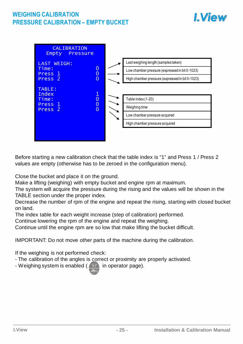
Before starting a new calibration check that the table index is “1” and Press 1 / Press 2 values are empty (otherwise has to be zeroed in the configuration menu).
Close the bucket and place it on the ground. Make a lifting (weighing) with empty bucket and engine rpm at maximum.The system will acquire the pressure during the rising and the values will be shown in the TABLE section under the proper index.Decrease the number of rpm of the engine and repeat the rising, starting with closed bucket on land. The index table for each weight increase (step of calibration) performed. Continue lowering the rpm of the engine and repeat the weighing. Continue until the engine rpm are so low that make lifting the bucket difficult.
IMPORTANT: Do not move other parts of the machine during the calibration.
If the weighing is not performed check:- The calibration of the angles is correct or proximity are properly activated. - Weighing system is enabled ( in operator page).
���!3�����&�)$(����B����B
�����A&�����C�B�����������������B���*��������������B���0������������
��!�&��F1B/�������������*�C�B�����������������B���*��������������B���0������������
D�92@/*+,*�+./�+2,69�;8./92�)/�7
D-@=,�;>/181/99<1/6/A81/99/�*�>*2!�&!�F7
B*+,=,�;>/181/99<1/6/A81/99/�*�>*2!�&!�F7
A�>./*��/A6&��!7
�/*+,*�+2*;/
D-@=,�;>/181/99<1/�=B<*1/�
B*+,=,�;>/181/99<1/�=B<*1/�
���BE�ABC�����D��A
���FF���C�����D��AC1 ���D$C���&�D

- 26 -I.View Installation & Calibration Manual
Pressing the key switch it is possible to check the pressure table.F5
Pressure index table. The number of points corresponds to the calibration rises.One of the two tables can have multiple points of a second made of rose LIGHT GREEN: low chamber empty table DARK GREEN: high chamber empty table RED: low chamber loaded tableORANGE: high chamber loaded table
Pre
ssur
e va
lue
(fro
m 0
to 1
023
bit)
.
When all the points are taken save the data permanently by means of the command Save on Calibration menu. If you switch off the power without save, you’ll loose all calibration data.
���BE�ABC�����D��A
���FF���C�����D��AC1 ���FF���CD���
- 27 -I.View Installation & Calibration Manual
���!3��������1B1���B����B
�����A&�����C�B�����������������B���*��������������B���0������������
��!�&��F1B/�������������*�C�B�����������������B���*��������������B���0������������
D�92@/*+,*�+./�+2,69�;8./92�)/�7
D-@=,�;>/181/99<1/6/A81/99/�*�>*2!�&!�F7
B*+,=,�;>/181/99<1/6/A81/99/�*�>*2!�&!�F7
A�>./*��/A6&��!7
�/*+,*�+2*;/
D-@=,�;>/181/99<1/�=B<*1/�
B*+,=,�;>/181/99<1/�=B<*1/�
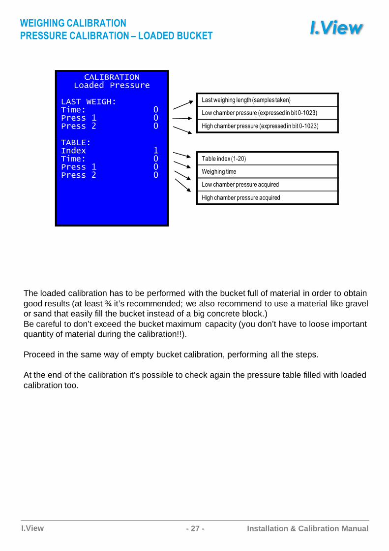
The loaded calibration has to be performed with the bucket full of material in order to obtain good results (at least ¾ it’s recommended; we also recommend to use a material like gravel or sand that easily fill the bucket instead of a big concrete block.)Be careful to don’t exceed the bucket maximum capacity (you don’t have to loose important quantity of material during the calibration!!).
Proceed in the same way of empty bucket calibration, performing all the steps.
At the end of the calibration it’s possible to check again the pressure table filled with loaded calibration too.
���BE�ABC�����D��A
���FF���C�����D��AC1 �����C���&�D
- 28 -I.View Installation & Calibration Manual
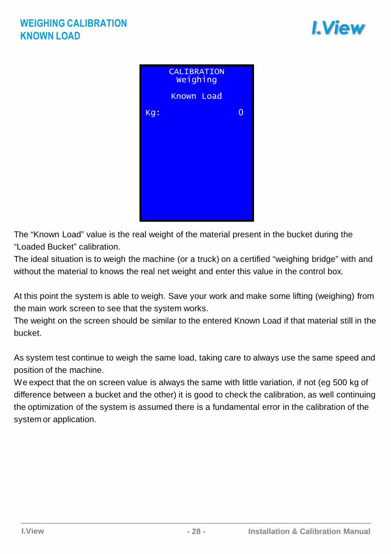
The “Known Load” value is the real weight of the material present in the bucket during the “Loaded Bucket” calibration. The ideal situation is to weigh the machine (or a truck) on a certified “weighing bridge” with and without the material to knows the real net weight and enter this value in the control box.
At this point the system is able to weigh. Save your work and make some lifting (weighing) from the main work screen to see that the system works.The weight on the screen should be similar to the entered Known Load if that material still in the bucket.
As system test continue to weigh the same load, taking care to always use the same speed and position of the machine.We expect that the on screen value is always the same with little variation, if not (eg 500 kg of difference between a bucket and the other) it is good to check the calibration, as well continuing the optimization of the system is assumed there is a fundamental error in the calibration of the system or application.
���!3�����ABCDECFD
4F��F����1
4D�����������������
���BE�ABC�����D��A
&A��AC���
- 29 -I.View Installation & Calibration Manual
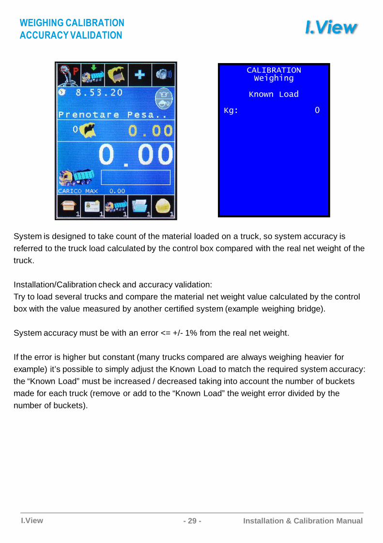
System is designed to take count of the material loaded on a truck, so system accuracy is referred to the truck load calculated by the control box compared with the real net weight of the truck.
Installation/Calibration check and accuracy validation:Try to load several trucks and compare the material net weight value calculated by the control box with the value measured by another certified system (example weighing bridge).
System accuracy must be with an error <= +/- 1% from the real net weight.
If the error is higher but constant (many trucks compared are always weighing heavier for example) it’s possible to simply adjust the Known Load to match the required system accuracy: the “Known Load” must be increased / decreased taking into account the number of buckets made for each truck (remove or add to the “Known Load” the weight error divided by the number of buckets).
���!3�����ABCDECFD
4F��F����1
4D�����������������
���BE�ABC�����D��A
�����$C����D��A

- 30 -I.View Installation & Calibration Manual
Parameters are values that can be modified only by the system installer.
Usually are a fine tuning of the system, but tot much dangerous/complicated to be available to
the end user.
%&�'
�C�DF��$C"
��C���$C�F
�F+CD���$C�F
�����B$B��
��,&
Enter
����D��F
- 31 -I.View Installation & Calibration Manual
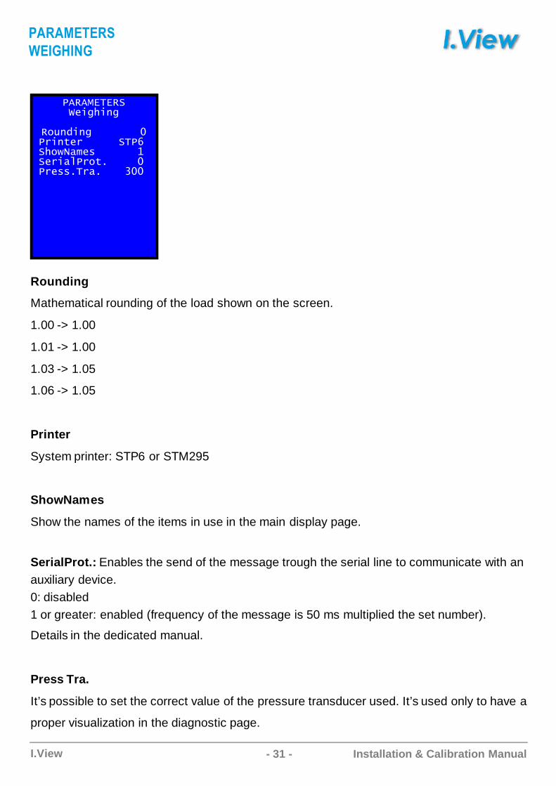
Rounding
Mathematical rounding of the load shown on the screen.
1.00 -> 1.00
1.01 -> 1.00
1.03 -> 1.05
1.06 -> 1.05
Printer
System printer: STP6 or STM295
ShowNames
Show the names of the items in use in the main display page.
SerialProt.: Enables the send of the message trough the serial line to communicate with an auxiliary device. 0: disabled1 or greater: enabled (frequency of the message is 50 ms multiplied the set number).
Details in the dedicated manual.
Press Tra.
It’s possible to set the correct value of the pressure transducer used. It’s used only to have a
proper visualization in the diagnostic page.
��3�%&�&3�ABCDECFD
3��F1CFD�����������CF$B����������8�E�����B��������*�B�C�����$ ��������B�� ��� ����9��
����D��F
���BE�AB
- 32 -I.View Installation & Calibration Manual
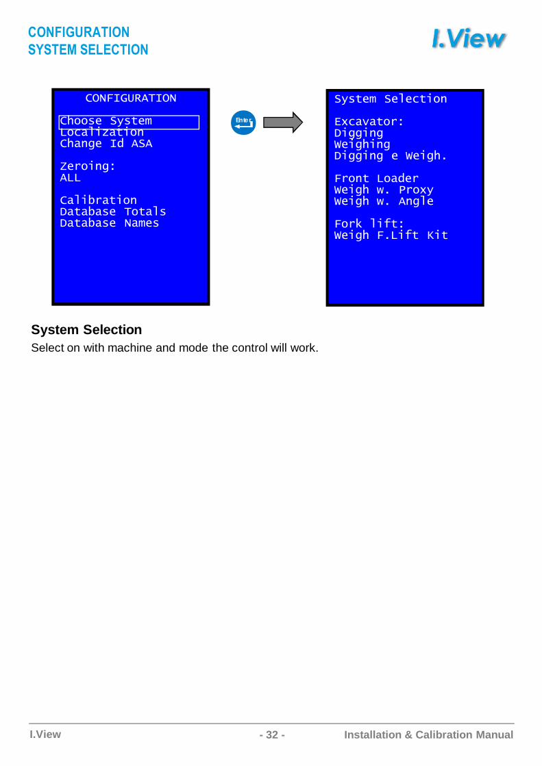
System SelectionSelect on with machine and mode the control will work.
��.��'3�����
E���B��(�$B���"��C:�$C�FE�FDB��1����
;B��CFD����
��C���$C�F��$����B���$�����$����B����B�
�(�$B���B�B"$C�F
&/"�7�$����CDDCFDABCDECFD�CDDCFD�B�ABCDE
.��F$����1B�ABCDE�� ����/(ABCDE�� ��FD�B
.��#��C+$�ABCDE�. �C+$�4C$
Enter
��A%�B��D��A
F$FD��CF����D��A
- 33 -I.View Installation & Calibration Manual
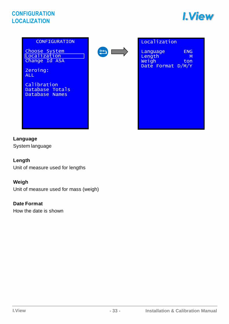
LanguageSystem language
LengthUnit of measure used for lengths
WeighUnit of measure used for mass (weigh)
Date FormatHow the date is shown
��.��'3�����
E���B��(�$B���"��C:�$C�FE�FDB��1����
;B��CFD����
��C���$C�F��$����B���$�����$����B����B�
��"��C:�$C�F
��FD��DB������&���BFD$E����������%ABCDE���������$�F��$B�.����$��-%-�
Enter
��A%�B��D��A
�����2D��A
- 34 -I.View Installation & Calibration Manual
��.��'3�����
E���B��(�$B���"��C:�$C�FE�FDB��1����
;B��CFD����
��C���$C�F��$����B���$�����$����B����B�
��.��'3������BF�����1
�"$�����1��������
�B���1���������89
%����3&&�,&�
Enter
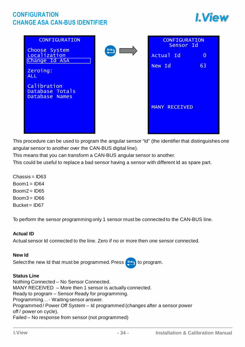
This procedure can be used to program the angular sensor “Id” (the identifier that distinguishes one angular sensor to another over the CAN-BUS digital line).This means that you can transform a CAN-BUS angular sensor to another.This could be useful to replace a bad sensor having a sensor with different Id as spare part.
Chassis = ID63Boom1 = ID64Boom2 = ID65Boom3 = ID66Bucket = ID67
To perform the sensor programming only 1 sensor must be connected to the CAN-BUS line.
Actual IDActual sensor Id connected to the line. Zero if no or more then one sensor connected.
New IdSelect the new Id that must be programmed. Press to program.
Status LineNothing Connected – No Sensor Connected.MANY RECEIVED – More then 1 sensor is actually connected.Ready to program – Sensor Ready for programming.Programming… - Waiting sensor answer.Programmed / Power Off System – Id programmed (changes after a sensor power off / power on cycle). Failed – No response from sensor (not programmed)
Ente r
��A%�B��D��A
�EAB�CFC�A���FC���AD�%���
- 35 -I.View Installation & Calibration Manual
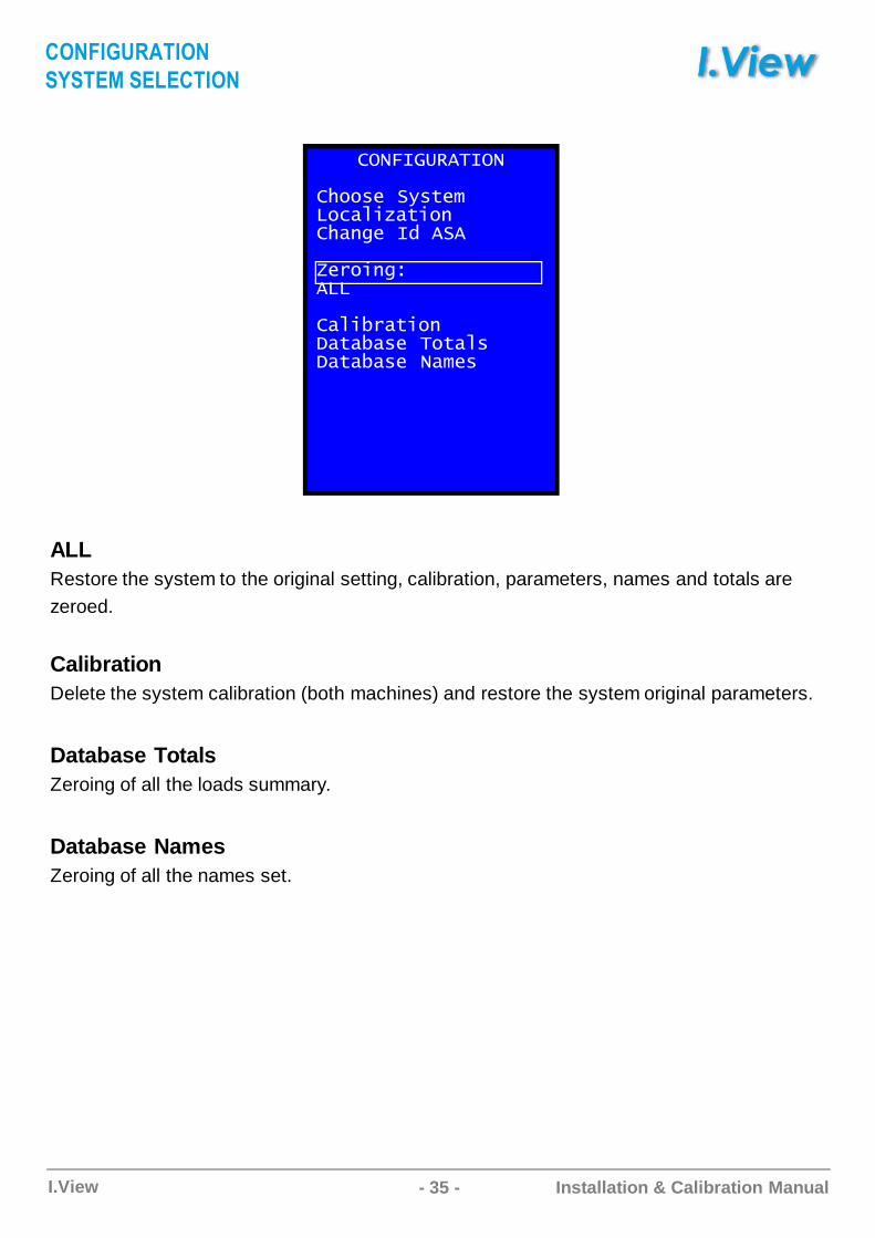
ALLRestore the system to the original setting, calibration, parameters, names and totals arezeroed.
CalibrationDelete the system calibration (both machines) and restore the system original parameters.
Database TotalsZeroing of all the loads summary.
Database NamesZeroing of all the names set.
��.��'3�����
E���B��(�$B���"��C:�$C�FE�FDB��1����
;B��CFD����
��C���$C�F��$����B���$�����$����B����B�
��A%�B��D��A
F$FD��CF����D��A
- 36 -I.View Installation & Calibration Manual
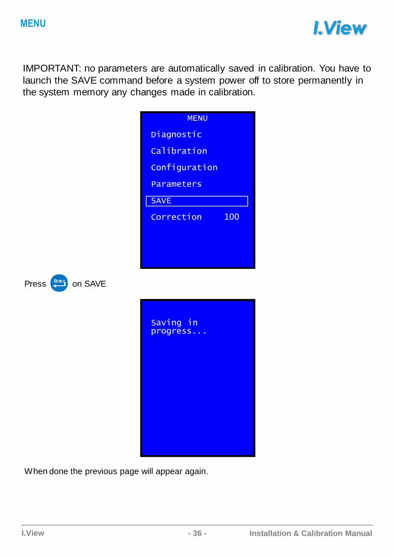
When done the previous page will appear again.
%&�'
�C�DF��$C"
��C���$C�F
�F+CD���$C�F
�����B$B��
��,&
���B"$C�F����*��
��7CFD�CF)��D�B��
IMPORTANT: no parameters are automatically saved in calibration. You have to launch the SAVE command before a system power off to store permanently in the system memory any changes made in calibration.
Press on SAVEEnte r
��A�
- 37 -I.View Installation & Calibration Manual
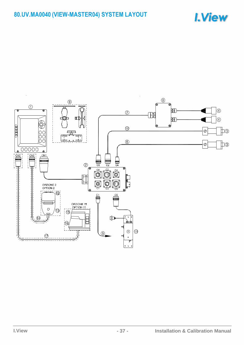
3��������#�C4������FD���#5CF$FD��C�$��D
- 38 -I.View Installation & Calibration Manual
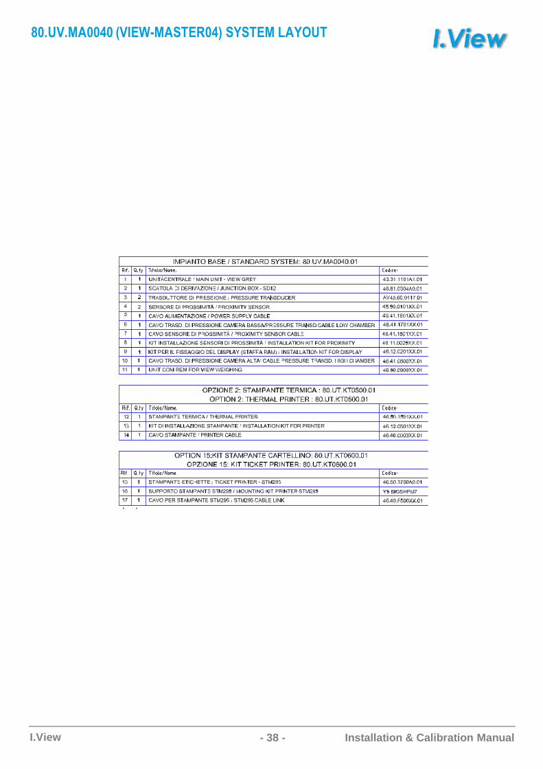
3��������#�C4������FD���#5CF$FD��C�$��D
- 39 -I.View Installation & Calibration Manual
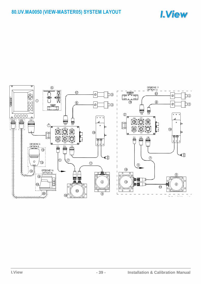
3����������C4������FD����5CF$FD��C�$��D
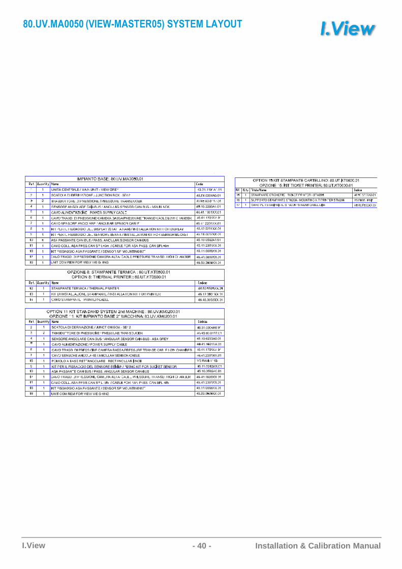
- 40 -I.View Installation & Calibration Manual
3����������C4������FD����5CF$FD��C�$��D
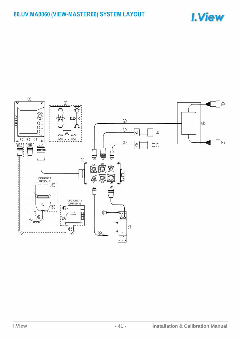
- 41 -I.View Installation & Calibration Manual
3�������� �C4������FD��� 5CF$FD��C�$��D
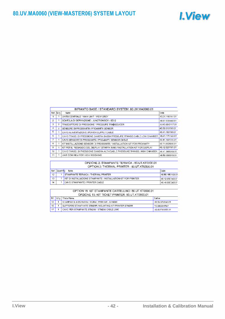
- 42 -I.View Installation & Calibration Manual
3�������� �C4������FD��� 5CF$FD��C�$��D

- 43 -I.View Installation & Calibration Manual
Informations in this document areprovided for only informative purpose.They can be changed without warningand don’t have to be understood assome C.O.B.O. S.p.A. - Divisione 3B6commitment.All rights reserved. Reproduction,adaptation or translation of this materialare forbidden without previous writtenC.O.B.O. S.p.A. - Divisione 3B6authorization, safe for how muchallowed by the laws on the rights ofauthor.The only guarantees of C.O.B.O.S.p.A. - Divisione 3B6 products andservices are those established in theexplicit declarations of guarantee thataccompany such products andservices. Nothing contained in thepresent document has value ofadditional guarantee.C.O.B.O. S.p.A. - Divisione 3B6 is notresponsible of technical or publishingerrors or omissions contained in thepresent document.C.O.B.O. S.p.A. - Divisione 3B6 is atrademark and it’s deposited in Italy.Any possible society reference ormarks quoted in the present publishingproduct is purely casual: it has onlyillustrative purpose and it excludes anyby-end. Names and terms used in thepresent document are C.O.B.O. S.p.A.- Divisione 3B6 creative ownership.
C.O.B.O. S.p.A. - Divisione 3B6Via Sivo, 7428053 Castelletto Sopra Ticino (Novara)ITALYTel. +39 0331 9286.1Fax +39 0331 [email protected]
Headquarters:C.O.B.O. S.p.A.Via Tito Speri, 1025024 Leno (Brescia)ITALYTel. +39 030 90451Fax +39 030 [email protected]