Embed Size (px)
Citation preview
Volume de l'accumulateur en litres
Volume of accumulator in liters
Temps de précharge de 0 à 1,5 bar en secondes
Pre-charging time 0 to 1.5 bar in seconds
1 105 2010 4050 120100 200200 400
1
2*
3*
4
5
6*
7*
8
Kit de rechange
Vessie Complète
Valve de Gonflage
Bouchon de Valve
Bague anti extrusion
Bague Caoutchoutée
Pochette Purgeur avec joint ( 1 )
Douille perforée
Repère Pièces de Rechange
1
2*
3*
4*
5*
6*
7*
8
Replacement Kit
Complete bladder
Filling valve
Valve plug
Retaining Ring
Sealing ring
Bleeder and ring (1)
Perforated bushing
Items Spare parts
(1) Depending on model
* These parts are delivered in a replacement kit with
explanatory notice.
(1) En fonction du modèle
* Ces pièces sont livrées sous forme de kit de rechange
avec notice explicative.
EBV
Au-dessus de la valeur 1,5 bar, continuer le gonflage à la valeur choisie.
When above 1,5 bar, continue charging to the required pressure
Installation
Co
nce
pti
on
et
imp
ress
ion
ID
AC
im
pri
me
rie
: 0
1 3
0 7
6 0
1 1
7 -
Do
cum
en
t n
on
co
ntr
act
ue
l su
sce
pti
ble
de
mo
dif
ica
tio
ns
san
s p
réa
vis
- R
éfé
ren
ce :
NA
EB
Vm
ain
t -
01
-FB
- A
vril
20
07
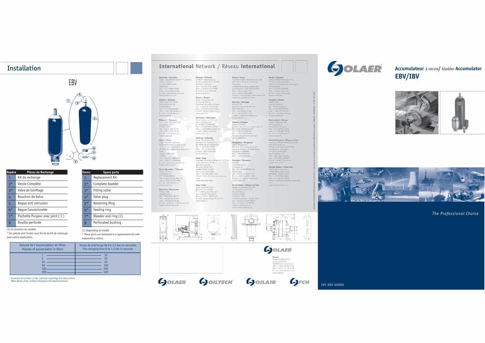
The Professional Choice
191 000 00000
Accumulateur à vessie/ bladder Accumulator
EBV/IBV
EBVDémontage/Remontage
Vous vous apprêtez à intervenir sur un accumulateur destiné à contenir
des fluides sous pression. Assurez-vous que l'accumulateur est conforme
à la réglementation en vigueur dans le pays d'utilisation et que vous dis-
posez :
- des documents délivrés avec l'accumulateur
- du matériel nécessaire à la maintenance des accumulateurs.
En cas de difficulté, contacter impérativement Olaer.
Toute action improvisée peut être la source d'un danger potentiel.
Le montage et démontage ne doivent être confiés qu'à des techniciens
qualifiés (s'adresser à Olaer ou à son réseau agréé).
DEMONTAGE DES ACCUMULATEURSAvant de déposer l'accumulateur du circuit hydraulique, il faut impérati-
vement relâcher la pression hydraulique du circuit et s'assurer de l'ab-
sence de pression hydraulique résiduelle au niveau de l'accumulateur.
A. Isoler l'accumulateur et décomprimer le circuit hydraulique à l'aide du
bloc de décompression et d'isolement DI Olaer ou décomprimer le circuit
hydraulique.
B. Déposer l'accumulateur, le fixer horizontalement dans un étau ou
tout autre système de fixation en protégeant le corps afin de ne pas l'endom-
mager. Délimiter une zone de sécurité hors alignement des ouvertures
C.Dévisser le bouchon protecteur de la valve de gonflage (photo 1).
D.Dévisser le bouchon de la valve de gonflage (photo 2)
E.Evacuer le gaz contenu dans la vessie à l'aide d'un vérificateur gonfleur
équipé d'un manomètre adapté à la pression de l'accumulateur jusqu'à ce
qu'il indique une pression 0 (photo 3). S'assurer que la vessie n'est plus en
pression d'azote en vérifiant qu'elle n'est plus en contact avec la crépine,
elle doit pouvoir bouger légèrement dans son logement.
IMPORTANT !
Si la vessie reste en appui sur la crépine voir schéma (voir schéma), cela
signifie qu'il y a une pression résiduelle. Dans ce cas :
- stopper toute opération
- sécuriser la zone
- contacter immédiatement OLAER
F.Retirer la valve de gonflage monobloc (photo 4) ou le mécanisme de valve
intégrée ou l'obus de valve (photo 5) suivant modèles
G.Retirer l'écrou de fixation du corps de valve ainsi que la plaque firme
(photo 6 et 7). En appuyant sur le corps de valve, repousser manuellement la
vessie à l'intérieur du corps. Il ne doit pas y avoir de résistance.
IMPORTANT !
S'il est impossible de repousser la vessie à l'intérieur , cela signifie qu'ily a une pression résiduelle. Dans ce cas :
- stopper toute opération- sécuriser la zone- contacter immédiatement OLAER
H.Suivant modèle, déposer la vis de purge hydraulique et son joint " vue
éclatée "
I.Retirer le jonc d'arrêt (photo 8).
J.Retirer la douille perforée (photo 9).
K.Extraire la vessie par l'ouverture côté bouche en veillant à ne pas l'endom-
mager (photo 10).
NETTOYAGE ET INSPECTIONNettoyer soigneusement toutes les pièces métalliques de l'accumulateur avec
un solvant organique.
Vérifier visuellement l'état des pièces montées.
Nettoyer la vessie avec un fluide compatible avec la nature du caoutchouc,
(alcool isopropylique,par exemple).
Vérifier que la vessie ne présente aucun défaut d'aspect.
Vérifier l'état de la crépine, corrosion, sertissage et soudure de la grille.
Vérifier qu'il n'y ait aucune trace de corrosion, ni de corps étrangers à l'inté-
rieur du corps de l'accumulateur.
Dans le cas où le corps de l'accumulateur est protégé intérieurement, vérifier
le bon état de la protection.
Pour toute inspection règlementaire, se référer à la réglementation en
vigueur.
Remplacer les pièces jugées défectueuses. Les joints, le jonc d'arrêt doivent
être obligatoirement changés (voir vue éclatée).
REMONTAGE DES ACCUMULATEURS
L.Evacuer l'air de la vessie en la comprimant (photo11).
M.Lubrifier abondamment l'intérieur du corps de l'accumulateur en le fai-
sant tourner autour de son axe. Employer soit le fluide utilisé dans le circuit
ou un produit similaire compatible avec le caoutchouc de la vessie (environ
10% du volume de l'accumulateur pour capacité jusqu'à 5 litres ou 5% pour
capacités supérieures. Dans le cas d'un fluide à faible viscosité (inférieur à 5
cSt).Consulter OLAER.
N.Lubrifier la vessie puis l'introduire dans le corps de l'accumulateur
(photo12). Contrôler que la vessie n'est pas pliée ou vrillée. Dans le cas d'ac-
cumulateur de grandes capacités, utiliser l'outillage approprié (tire-vessie).
O.Remonter la plaque firme et l'écrou de fixation sans bloquer ce
dernier.(photo 13)
P.Introduire la douille perforée jusqu'à la mettre en butée dans le corps de
l'accumulateur (photo 14).
Q.Monter impérativement un jonc neuf en veillant particulièrement à sa
bonne mise en place dans la gorge prévue à cet effet (photo 15).
R.Suivant modèle, remonter précautionneusement la vis de purge avec son
joint neuf, en veillant à bien l'engager.
S.Côté azote, visser l'écrou du corps de valve en maintenant celui-ci par les
méplats appropriés (photo 16). Il est impératif que le corps de valve ne
tourne pas.
T.Mettre en place la valve de gonflage monobloc au couple de 1.5 mdaN ou
la valve intégrée ou l'obus de valve suivant couple 0.03 mda.N (photo 17).
U.IMPERATIVEMENT ET POUR DES RAISONS DE SECURITE : Visser côté fluide
un raccord non percé, qui doit rester présent pendant toute l'opération de
gonflage
V.Le montage d'un détendeur entre la bouteille et le vérificateur gonfleur
est obligatoire.
W.Avant de gonfler à l'azote l'accumulateur, faire tourner autour de son axe
le corps de l'accumulateur afin d'obtenir une parfaite lubrification de toute
la paroi interne de celui-ci.
RAPPEL : Utiliser uniquement de l'azote pur à 99,8% minimum en volume
(type R,S,U). Il est formellement interdit de gonfler l'accumulateur avec tout
autre fluide que l'azote. Risque d'explosion !
Immédiatement après effectuer lentement l'expansion de la vessie sous une
pression d'azote de 1 à 1.5 bar (accumulateur en position horizontale :
cf.tableau processus de gonflage).
Pour le gonflage de l'accumulateur et la mise en service, se conformer à la
notice d'instructions.
RAPPEL : la pression de gonflage pour les accumulateurs basse pression ne
doit jamais excéder 20 Bar à la température maxi d'utilisation
Enfin vous assurer que les avertissements de sécurité initiaux (plaque firme,
étiquette de gonflage, informations sécurité…) sont toujours lisibles. Si ce
n'est pas le cas consulter Olaer pour fourniture.
Dismantling/Reassembly
You are on the point of intervening on an accumulator designed to contain
fluids under pressure. Make sure that the accumulator is compliant with the
rules existing in the country of use and that you have the following:
- documents delivered with the accumulator
- equipment necessary for the maintenance of accumulators.
In case of difficulty, immediately contact Olaer.
Any improvised action can be the source of a potential danger.
The equipment must only be commissioned by qualified technicians only
(contact Olaer or its approved network).
DISMANTLING OF ACCUMULATORSBefore removing the hydraulic system, the hydraulic pressure must be impe-
ratively released from the system. Make sure that there is no residual
hydraulic pressure in the accumulator.
A. Isolate the accumulator and depressurize the hydraulic system using the
Olaer DI depressurizing or isolating block or depressurize the hydraulic system.
B. Remove the accumulator and fix it horizontally in a vice or another securing
device. Protect the shell so as not to damage it. Delimit a security area outside
the alignment of openings
C.Unscrew the guard cap from the charging valve (photo 1).
D.Unscrew the charging valve plug (photo 2)
E.Discharge the gas contained in the bladder using a charging and gauge
assembly until 0 is shown in the manometer(photo 3). Make sure that the blad-
der is not charged with nitrogen by checking that it is no longer in contact with
the grid, it must be able to move slightly in its housing
IMPORTANT!
If the bladder remains in contact with the grid see diagram (see diagram),
it means that there is residual pressure. In this case:
- stop all operation
- secure the area
- contact OLAER immediately
F.Remove the single piece charging valve (photo 4) or the integrated valve
mechanism or the valve core (photo 5) according to the models.
G.Remove the lock nut from the valve body and the name plate (photo 6 and
7). By pressing on the valve body, manually push back the bladder inside the
body. There must be no resistance.
IMPORTANT!If it is not possible to push back the bladder inside, it means that there is
residual pressure. In this case:
- stop all operation
- secure the area
- contact OLAER immediately
H.According to the model, remove the hydraulic vent screw and its seal (see
exploded view photo)
I.Remove the spring ring (photo 8).
J.Remove the polyliner (photo 9).
K.Remove the bladder through the fluid port opening, taking care not to
damage it (photo 10).
CLEANING AND INSPECTIONCarefully clean all the metallic parts of the accumulator with an organic sol-
vent.
Visually check the condition of the installed components.
Clean the bladder with a fluid compatible with the type of rubber, (for exam-
ple, isopropyl alcohol).
Check that the surface of the bladder is not damaged.
Check the condition of the grid, corrosion, crimping and welding of the grill.
Check that there is no corrosion, or foreign bodies inside the accumulator
shell.
If the inside of the accumulator shell is protected, check the condition of the
protection.
For any statutory inspection, refer to the existing regulations.
Replace all parts considered to be defective. The seals and spring ring must be
replaced (see exploded view).
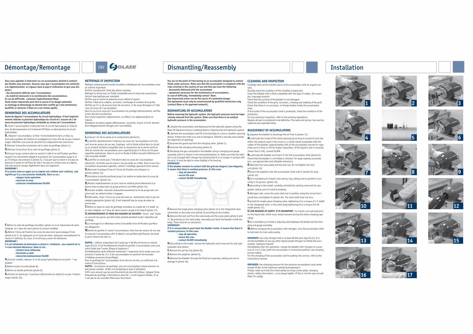
REASSEMBLY OF ACCUMULATORS
L.Squeeze the bladder to discharge the air from it (photo 11).
M.Lubricate the inside of the shell copiously by turning it around its axis.Use
either the medium used in the circuit or a similar liquid compatible with the
rubber of the bladder (approximately 10% of the accumulator volume for capa-
cities up to 5 litres or 5% for higher capacities). If the liquid is low in viscosity
(lower than 5 cSt), consult OLAER
N.Lubricate the bladder and insert it into the accumulator shell (photo12).
Check that the bladder is not folded or twisted. For large capacity accumula-
tors, use appropriate tools (bladder extractor).
O.Reinstall the name plate and the lock nut. Do not tighten the lock
nut.(photo 13)
P.Insert the polyliner into the accumulator shell until it reaches its stop.
(photo 14).
Q.It is mandatory to install a new spring ring, taking care to position it cor-
rectly in its groove. (photo 15).
R.According to the model, carefully reinstall the venting screw and its new
gasket, taking care to install it properly.
S.Nitrogen side, screw the valve shell nut in position using the correct hori-
zontal bars and tighten it.(photo 16). The valve shell must not turn.
T.Install the single-piece charging valve, tightening it to a torque of 1.5 mdaN
or the integrated valve or the valve body tightening it to a torque of 0.03
mdaN (photo 17).
U.FOR REASONS OF SAFETY, IT IS MANDATORY : to install a non-pierced joint
on the liquid side, which must remain present during the entire charging ope-
ration
V.It is mandatory to install a reducing valve between the bottle and the char-
ging and gauge assembly.
W.Before charging the accumulator with nitrogen, turn the accumulator shell
to lubricate its inner walls evenly.
REMINDER! Use only nitrogen that is at least 99.8% pure (typ R,S,U). It is
strictly forbidden to use any other liquid except nitrogen to inflate the accu-
mulator. Explosion hazard!
Immediately after this operation, charge the bladder with nitrogen to a pres-
sure of 1 to 1.5 bar (with the accumulator in horizontal position: see charging
process table).
For the charging of the accumulator and its putting into service, refer to the
instructions manual.
REMINDER: the charging pressure for low pressure accumulators must never
exceed 20 Bar at the maximum operating temperature
Finally, make sure that the initial safety warnings (name plate, charging
sticker, safety information…) are always legible. If this is not the case consult
Olaer for supply.
1
9
5
87
2
10 11
6
15
12
14
4
13
16 17
3
Installation