Embed Size (px)
Citation preview

Installation Guide
DEVIlink™ CCCentral Controller
www.DEVI.com

DEVIlink™ CC
Installation Guide2
Table of Contents
1 Introduction � � � � � � � � � � � � � � � � � � � � � � � � � � � � � � � � � � � � 4
2 Guidelines for installation � � � � � � � � � � � � � � � � � � � � � � � 5
3 Installation plan� � � � � � � � � � � � � � � � � � � � � � � � � � � � � � � � � 6
3.1 Correct installation plan . . . . . . . . . . . . . . . . . . . . . . . . .6
3.2 Incorrect installation plan . . . . . . . . . . . . . . . . . . . . . . . .7
3.3 Repeater units . . . . . . . . . . . . . . . . . . . . . . . . . . . . . . . . . . .8
4 Installation� � � � � � � � � � � � � � � � � � � � � � � � � � � � � � � � � � � � � � 9
4.1 Preparing to add devices. . . . . . . . . . . . . . . . . . . . . . . 11
4.2 Initial settings . . . . . . . . . . . . . . . . . . . . . . . . . . . . . . . . . 12
4.3 Start up the installation menu . . . . . . . . . . . . . . . . . 12
4.4 Creating rooms . . . . . . . . . . . . . . . . . . . . . . . . . . . . . . . . 13
4.5 Adding mains powered devices . . . . . . . . . . . . . . . . 14
4.6 Adding service devices - mains powered . . . . . . . 14
4.7 Adding room devices - mains powered. . . . . . . . . 15
4.8 Adding room devices - battery powered . . . . . . . 17
4.9 Performing network test . . . . . . . . . . . . . . . . . . . . . . . 17
4.10 Finalising the installation . . . . . . . . . . . . . . . . . . . . . . 19

DEVIlink™ CC
3Installation Guide
5 Modifying an existing installation� � � � � � � � � � � � � � � 19
5.1 Adding devices to an existing room . . . . . . . . . . . . 19
5.2 Changing parameters for heat regulations . . . . . 21
5.3 Removing a room or a service device. . . . . . . . . . . 23
5.4 Factory reset of DEVIlink™ CC . . . . . . . . . . . . . . . . . . 24
6 Upgrading software version � � � � � � � � � � � � � � � � � � � � 24
7 Warnings� � � � � � � � � � � � � � � � � � � � � � � � � � � � � � � � � � � � � � � 26
7.1 Alert Icons . . . . . . . . . . . . . . . . . . . . . . . . . . . . . . . . . . . . . 27
8 Technical specifications and approvals � � � � � � � � � � 28
9 Warranty� � � � � � � � � � � � � � � � � � � � � � � � � � � � � � � � � � � � � � � 30
10 Disposal instructions � � � � � � � � � � � � � � � � � � � � � � � � � � � 30

DEVIlink™ CC
Installation Guide4
1 Introduction
The DEVIlink™ is a programmable, wireless control system for heating systems in residential buildings (up to approximately 300 m2).
The DEVIlink™ CC is the central control unit. It has a colour touch screen from where the entire installation can be controlled.
This installation guide contains all information about the DEVIlink™ CC and how to get started.
It guides you through recommendations and considera-tions that must be taken into account when handling a wireless system - and it describes the configuration of the system, to ensure a correct and reliable system set-up.
!Individual instructions, supplied with the service and room devices, contain information about connecting the respective devices to the network. The instruction will also state whether the device is considered a service device or a room device.
The ? key can be used at any point during installation.
Always look for the latest software version at www.DEVI.com before installation. See "6 Upgrading software version".

DEVIlink™ CC
5Installation Guide
2 Guidelines for installation
The signal strength is sufficient for most applications, however, wireless signals are weakened on the way from the DEVIlink™ CC to the room devices and every building has different obstacles.
Ensure the best performance by keeping the following in mind for planning and installation:
• Max. 30 m between devices in free space.
• Receiving devices should be placed on opposite or next wall as the transmitter, if possible.
• All metal objects in the building construction can weaken wireless signals.
• Reinforced concrete walls and floors weaken the signal strength significantly, but almost any types of construction materials reduce the signal to some degree.
• Corners that are a result of the building design, can weaken the wireless signals, due to either long dis-tances or inadequate reflecting opportunities.
Note! These are guidelines only as many factors have influ-ence on wireless communication.

DEVIlink™ CC
Installation Guide6
3 Installation plan
DEVI recommends that an installation plan is made before beginning the actual installation.
1. Create an installation plan of all the room devices (mains powered and battery powered).
2. Add the DEVIlink™ CC in a central location to the installation plan.
3. Add necessary repeater units (if any) to the installation plan. DEVI recommends that you include at least one repeater unit within 5 meters from the CC.
3�1 Correct installation plan
• No metal objects between the DEVIlink™ CC and other wireless DEVI units.
• The DEVIlink™ CC is installed as central as possible on the floor plan (max. 30 m between devices in free space).
• Wireless signal through walls on shortest possible diagonal distance.
!RS Sensor
(room device)DEVIlink™ HC
(service device)
DEVIlink™ CC
living connect (room device)
living connect (room device)

DEVIlink™ CC
7Installation Guide
• No metal objects between the DEVIlink™ CC and other wireless DEVI units.
• The DEVIlink™ CC is installed as central as possible on the floor plan (max. 30 m between devices in free space).
• Wireless signal through walls on shortest possible diagonal distance.
RS Sensor(room device)
DEVIlink™ HC (service device)
DEVIlink™ CC
living connect (room device)
living connect (room device)
3�2 Incorrect installation plan
• Metal objects between the DEVIlink™ CC and other wireless DEVI units.
• Decentral installation of the DEVIlink™ CC.
• Crossing walls diagonally.
!! !
RS Sensor(room device) Danfoss link™ HC
(service device)
DEVIlink™ CC
living connect (room device)
living connect (room device)

DEVIlink™ CC
Installation Guide8
3�3 Repeater units
A repeater unit strengthens the wireless signal when a satisfying connection can not be established between the DEVIlink™ CC and other wireless DEVI mains powered devices.
Repeater units can be ordered on stock code no. 088U0230.
Placing repeater units
Plan view, single floor building
CC - central controller FT - floor thermostat (room device)HC - hydronic controller (service device)RS - room sensor (room device)RU - repeater unit (service device)living connect - radiator thermostat (room device)
RS FT
FT
CCRU
HC
living connect
living connect
FT
RS
RS
RS
DEVIlink™ CC
9Installation Guide
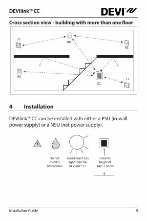
Cross section view - building with more than one floor
4 Installation
DEVIlink™ CC can be installed with either a PSU (in-wall power supply) or a NSU (net power supply).
CC
RS
RS
RU
FT
FT
!
Do not install in
bathrooms
Avoid direct sun light onto the DEVIlink™ CC
Install in height of
140 - 170 cm

DEVIlink™ CC
Installation Guide10
Mounting the DEVIlink™ CC with In-Wall PSU • Hold the PSU over the wall box and
mark up the 4 screw holes. Make sure the top is level.
• Drill holes and insert fitting plugs.
• Connect the PSU according to the connection diagram on the back side.
• Mount the PSU with the 4 screws.
• Do not connect the DEVIlink™ CC yet!
Mounting the DEVIlink™ CC with NSU• Place the mounting plate on the wall and mark up the
4 screw holes. Make sure the top is level.
• Drill holes and insert fitting plugs.
• Fasten the mounting plate with the 4 screws.
• Do not connect the DEVIlink™ CC yet!
• Connect the NSU to a power outlet.
PSU
UP
UP
NSU

DEVIlink™ CC
11Installation Guide
4�1 Preparing to add devices
When adding devices to the DEVIlink™ system, the distance between the DEVIlink™ CC and the device must not exceed 1.5 m. To accomplish this the DEVIlink™ Battery Supply Unit (BSU) is offered as an installation tool.
1. Slide off the lid and insert the batteries.
2. Slide the lid back on and attach the DEVIlink™ BSU battery pack onto the back of the DEVIlink™ CC. When ready to do the commissioning, turn the switch located on the DEVIlink™ BSU to the ON position.
The DEVIlink™ CC will now start up. This takes approxi-mately 30 seconds.
A battery pack (BSU) can be ordered on stock code no. 014G0262.
01
+
-
x 10
1.5 V AA
DEVIlink™ CC
Installation Guide12
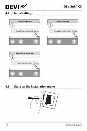
4�2 Initial settings
?
Select Language
Scroll down to select
1
?
Select Country
Scroll down to select
2
?
Select date and time
Set date and time
3
4�3 Start up the installation menu

DEVIlink™ CC
13Installation Guide
• Remove the front cover of the DEVIlink™ CC by gently pulling it off, pull near the edges of the cover.
• Press the [SETUP] pin for 3 seconds to enter the service area.
4�4 Creating rooms
DEVI recommends to create all the rooms before adding devices.
?
Service Options
Rooms and Devices
1
?
Rooms and Devices
Add New Room
2
?
Edit Room Name
Enter/edit Room Name
3
Tip! A list of common room names is available here ABC .

DEVIlink™ CC
Installation Guide14
4�5 Adding mains powered devices
• Pair devices to DEVIlink™ CC.
• Start with the device closest to the DEVIlink™ CC, and move outwards.
4�6 Adding service devices - mains powered
! Always add dedicated repeater units first!
Power-up all service devices and room devices (mains powered as well as battery powered).
The DEVIlink™ CC supports many different types of service devices which can function as simple ON/OFF devices for other electrically equipment as well as repeater units and controllers for hydronic systems and other sub-systems.
Press the [SETUP] pin for 3 seconds to enter the service area.
1st
2nd3rd
DEVIlink™ CC
15Installation Guide
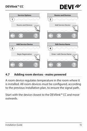
?
Service Options
Rooms and Devices
1
?
Rooms and Devices
Add Service Device
2
?
Add Service Device
Begin Registration
3
?
Edit Device Name
Enter / edit Device Name
4
4�7 Adding room devices - mains powered
A room device regulates temperature in the room where it is installed. All room devices must be configured, according to the previous installation plan, to ensure the signal path.
Start with the device closest to the DEVIlink™ CC and move outwards.

DEVIlink™ CC
Installation Guide16
?
Configure Room
Room Device
1
?
Room Device
Scroll down to select
2
?
Add Room Device
Begin Registration
3
?
Room Device
The configuration is valid
4
Press
Note! ON / OFF relays are only visible in the end-user menu.
Note! DEVIlink™ CC automatically selects the regulation principle according to the types of devices in the room. To change regulation principle, see "5.2 Changing parameters for heat regulations"
DEVIlink™ CC
17Installation Guide
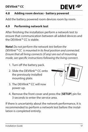
4�8 Adding room devices - battery powered
Add the battery powered room devices room by room.
4�9 Performing network test
After finishing the installation perform a network test to ensure that communication between all added devices and the DEVIlink™ CC is stable.
Note! Do not perform the network test before the DEVIlink™ CC is mounted in its final position and connected. Ensure that all living connects (if any) are out of mounting mode, see specific instructions following the living connect.
1. Turn off the battery pack.
2. Slide the DEVIlink™ CC onto the previously installed mounting plate.
3. The DEVIlink™ CC will now power-up.
4. Remove the front cover and press the [SETUP] pin for 3 seconds to enter the service area.
If there is uncertainty about the network performance, it is recommended to perform a network test before the instal-lation is completed entirely.

DEVIlink™ CC
Installation Guide18
?
Service Options
Status and Diagnostics
1
?
Status and Diagnostics
Network
2
?
Wireless Network Status
Start Network Test
3
At the end of the network test the DEVIlink™ CC waits for all battery operated devices to wake up and report. Follow the instructions given on screen.
If the network test is running correctly, there will be no need for further interaction.
If the network test is performing slow, the DEVIlink™ CC guides you through troubleshooting and provides useful tips for speeding up the process.

DEVIlink™ CC
19Installation Guide
4�10 Finalising the installation
Press the [SETUP] pin to close the installa tion.
?
10:15
1
5 Modifying an existing installation
5�1 Adding devices to an existing room
Remove the front cover and press the [SETUP] pin for 3 seconds to enter the service area.
?
Service Options
Rooms and Devices
1
?
Rooms and Devices
Manage Existing Room
2

DEVIlink™ CC
Installation Guide20
?
Manage Existing Room
Configure Existing Room
3
?
Select Room
Choose room
4
?
Configure Room
Room devices
5
?
Room Devices
Add a device
6
?
Add Room Device
Begin Registration
7
Continue until all new devices are added to the desired room.
! Perform a network test after modifying the installation.
DEVIlink™ CC
21Installation Guide
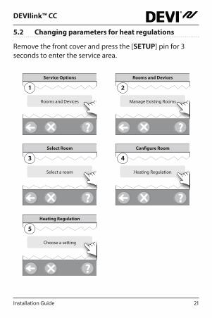
5�2 Changing parameters for heat regulations
Remove the front cover and press the [SETUP] pin for 3 seconds to enter the service area.
?
Service Options
Rooms and Devices
1
?
Rooms and Devices
Manage Existing Rooms
2
?
Select Room
Select a room
3
?
Configure Room
Heating Regulation
4
?
Heating Regulation
Choose a setting
5

DEVIlink™ CC
Installation Guide22
• Forecasting method: When activating the forecast method, the system will automatically predict the heat-ing start-up time necessary to reach the desired room temperature at the desired time (all heat emitter types).
• Maximum floor temperature: The default setting is 35 °C (electrical floor heating).
• Regulation type: Only in connection with electrical heating systems.
Note! Use pincode [0044] to change between the following regulation types:
Room sensor (regulates only by room temperature) - if only DEVIlink™ RS is fitted (hydronic floor heating) or DEVIlink™ RS + DEVIlink™ FT (electrical heating).
Floor sensor (regulates only by floor temperature ) - if only DEVIlink™ FT/S is fitted.
Combined room/floor (ensures min. floor temperature and regulates room temperature in parallel) - DEVIlink™ RS + DEVIlink™ FT/S is fitted.
In case of hydronic floor heating, be aware if a certain max. floor temperature is given by the floor manufacturer. This can be assured by fitting a thermostatically controlled mix-ing shunt.
DEVIlink™ CC
23Installation Guide
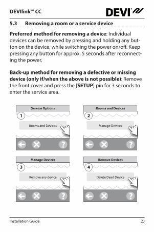
5�3 Removing a room or a service device
Preferred method for removing a device: Individual devices can be removed by pressing and holding any but-ton on the device, while switching the power on/off. Keep pressing any button for approx. 5 seconds after reconnect-ing the power.
Back-up method for removing a defective or missing device (only if/when the above is not possible): Remove the front cover and press the [SETUP] pin for 3 seconds to enter the service area.
?
Service Options
Rooms and Devices
1
?
Rooms and Devices
Manage Devices
2
?
Manage Devices
Remove any device
3
?
Remove Devices
Delete Dead Device
4
DEVIlink™ CC
Installation Guide24
To replace a device, while retaining all settings for that device, use the function [Replace any device] and follow the instructions given on the screen.
By using this function, all settings for that particular device, are transferred to the new unit.
5�4 Factory reset of DEVIlink™ CC
!All assigned rooms and all added devices will be removed from the system! It is recommended to remove all devices individually before resetting to factory default or replacing the DEVIlink™ CC.
Remove the front cover and press and hold the reset button on the right side of the DEVIlink™ CC, until the control-ler gives a clear beep. All rooms are now deleted and the DEVIlink™ CC is reset to factory settings.
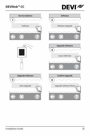
6 Upgrading software version
DEVIlink™ software is upgradable. New software versions are published on www.DEVI.com.
1. Download the software upgrade to a USB key, and insert the USB key in the USB port.
2. Remove the front cover and press the [SETUP] pin for 3 seconds to enter the service area.
DEVIlink™ CC
25Installation Guide
?
Service Options
Software
1
?
Software
Software Upgrade
2
?
Upgrade Software
Insert USB Stick
4
?
Upgrade Software
Start Upgrade
5
?
Confirm Upgrade
Upgrade Software Now!
6

DEVIlink™ CC
Installation Guide26
7 Warnings
!If a warning or an alert occurs, a yellow alert icon will be shown on the standby screen. Follow the procedure to find more information.
?
1
?
Start
House Control
2
?
House Control
Alerts
3
!
DEVIlink™ CC
27Installation Guide
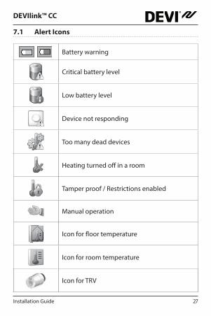
7�1 Alert Icons
Battery warning
Critical battery level
Low battery level
Device not responding
Too many dead devices
Heating turned off in a room
Tamper proof / Restrictions enabled
Manual operation
Icon for floor temperature
Icon for room temperature
Icon for TRV

DEVIlink™ CC
Installation Guide28
8 Technical specifications and approvals
DEVIlink™ CC
Operation voltage 15 V DC ±10%
Standby power consumption Max. 2 W
Screen 3.5” TFT colour w. touch
Ambient temperature -10 to +40 °C
Storage temperature -20 to +65 °C
Ball pressure test temperature 75 °C
Pollution degree 2 (domestic use)
Transmission frequency 868.42 MHz
Transmission range Up to 30 m
Max. repeaters in a chain 3
Transmission power Max. 1 mW
Software class A
IP class 21
Dimensions 125 x 107 x 25 mm
Weight 179 g

DEVIlink™ CC
29Installation Guide
DEVIlink™ PSU (In-Wall)
Operation voltage 100-250 V AC 50/60 Hz
Recommended protection fuse Max. 16 A
Output voltage 15 V DC ±10%
Standby power consumption Max. 0.15 W
Max. load 10 W
Cable specifications Recommended 1.5 mm2,
max. 2 x 2.5 mm2
DEVIlink™ NSU (Net Adapter)
Operation voltage 100-240 V AC 50/60 Hz
Recommended protection fuse Max. 16 A
Output voltage 15 V DC ±10%
Standby power consumption Max. 0.3 W
Cable length 2.5 m
Max. load 7 W
DEVIlink™ BSU (Battery Supply Unit)
Output voltage 15 V DC ±10%
Number of batteries 10 x AA

DEVIlink™ CC
Installation Guide30
The DEVIlink™ CC is tested for safety and EMC requirements as specified in EN60730-1 and EN60730-2-9.
9 Warranty
10 Disposal instructions
DEVIlink™ CC
31Installation Guide Produced by Danfoss © 03/201408095908 & VICKA302
Danfoss A/S Electric Heating SystemsUlvehavevej 617100 VejleDenmark
Phone: +45 7488 8500Fax: +45 7488 8501E-mail: [email protected]: www.DEVI.com
Danfoss can accept no responsibility for possible errors in catalogues, brochures and other printed material. Danfoss reserves the right to alter its products without notice. This also applies to products already on order provided that such alterations can be made without subsequential changes being necessary in specifications already agreed. All trademarks in this material are property of the respective companies. DEVI and the DEVI logo-type are trademarks of Danfoss A/S. All rights reserved

DEV
Ilink
™ C
C w
ith
PSU
140F
1076
EN
Cent
ral C
ontr
olle
r15
V 50
-60H
z-1
0°C
to +
40°C
16 A
IP 2
1
Pro
du
ct d
ocu
men
tati
on
Des
igne
d in
Den
mar
k fo
r Dan
foss
A/S
*08095908*
5703466232460
dMA