Embed Size (px)
Citation preview
The Medical Center Company Mechanical System Installation Requirements - version 12.10.1
Page 1 of 24
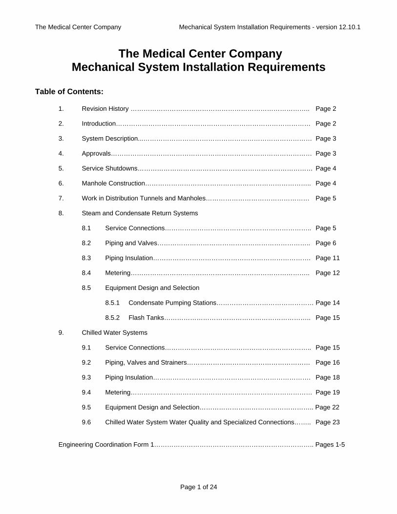
The Medical Center Company Mechanical System Installation Requirements
Table of Contents: 1. Revision History ……………………………………………………………………….. Page 2 2. Introduction……………………………………………………………………………… Page 2 3. System Description...…………………………………………………………………… Page 3 4. Approvals………………………………………………………………………………… Page 3 5. Service Shutdowns……………………………………………………………………… Page 4 6. Manhole Construction………………………………………………………………….. Page 4 7. Work in Distribution Tunnels and Manholes………………………………………… Page 5 8. Steam and Condensate Return Systems 8.1 Service Connections………………………………………………………….. Page 5 8.2 Piping and Valves…………………………………………………………….. Page 6 8.3 Piping Insulation………………………………………………………………. Page 11 8.4 Metering……………………………………………………………………….. Page 12 8.5 Equipment Design and Selection 8.5.1 Condensate Pumping Stations……………………………………… Page 14 8.5.2 Flash Tanks………………………………………………………….. Page 15 9. Chilled Water Systems 9.1 Service Connections………………………………………………………….. Page 15 9.2 Piping, Valves and Strainers………………………………………………… Page 16 9.3 Piping Insulation………………………………………………………………. Page 18 9.4 Metering………………………………………………………………………… Page 19 9.5 Equipment Design and Selection…………………………………………….. Page 22 9.6 Chilled Water System Water Quality and Specialized Connections…….. Page 23 Engineering Coordination Form 1……………………………………………………………….. Pages 1-5
The Medical Center Company Mechanical System Installation Requirements - version 12.10.1
Page 2 of 24
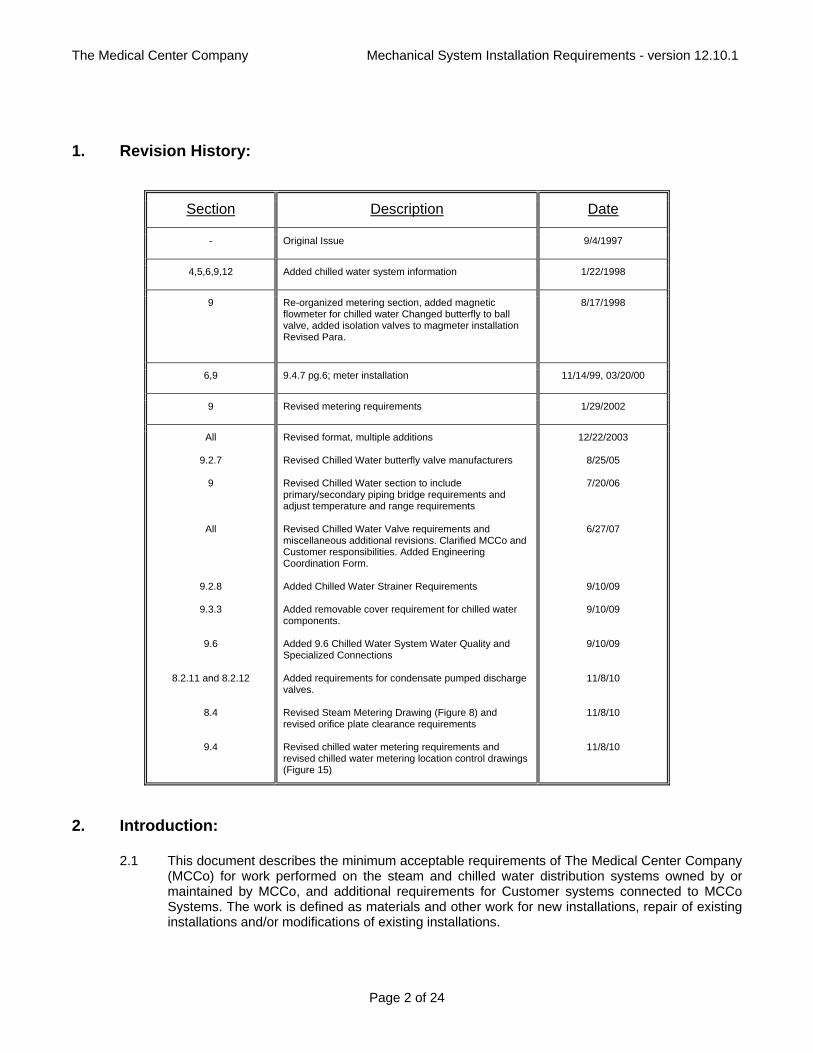
1. Revision History:
Section Description Date
- Original Issue 9/4/1997
4,5,6,9,12 Added chilled water system information 1/22/1998
9 Re-organized metering section, added magnetic flowmeter for chilled water Changed butterfly to ball valve, added isolation valves to magmeter installation Revised Para.
8/17/1998
6,9 9.4.7 pg.6; meter installation 11/14/99, 03/20/00
9 Revised metering requirements 1/29/2002
All
9.2.7
9
All
9.2.8
9.3.3
9.6
8.2.11 and 8.2.12
8.4
9.4
Revised format, multiple additions Revised Chilled Water butterfly valve manufacturers Revised Chilled Water section to include primary/secondary piping bridge requirements and adjust temperature and range requirements Revised Chilled Water Valve requirements and miscellaneous additional revisions. Clarified MCCo and Customer responsibilities. Added Engineering Coordination Form. Added Chilled Water Strainer Requirements Added removable cover requirement for chilled water components. Added 9.6 Chilled Water System Water Quality and Specialized Connections Added requirements for condensate pumped discharge valves. Revised Steam Metering Drawing (Figure 8) and revised orifice plate clearance requirements Revised chilled water metering requirements and revised chilled water metering location control drawings (Figure 15)
12/22/2003
8/25/05
7/20/06
6/27/07
9/10/09
9/10/09
9/10/09
11/8/10
11/8/10
11/8/10
2. Introduction:
2.1 This document describes the minimum acceptable requirements of The Medical Center Company (MCCo) for work performed on the steam and chilled water distribution systems owned by or maintained by MCCo, and additional requirements for Customer systems connected to MCCo Systems. The work is defined as materials and other work for new installations, repair of existing installations and/or modifications of existing installations.
The Medical Center Company Mechanical System Installation Requirements - version 12.10.1
Page 3 of 24
2.2 All applicable work shall conform to these Requirements and to the latest editions of applicable national, state and local codes and ordinances.
2.3 In general, and unless otherwise agreed upon by MCCo shall be responsible for installation and maintenance of service utility piping up to a mutually agreed upon termination point, typically in the proximity of the building utility entrance, or just inside a series of connected buildings to the isolation shut-off valve immediately downstream of MCCo's metering equipment for steam service and upstream of MCCo's metering equipment for chilled water service. MCCo will provide main line shut-off valves typically within the building upstream and downstream of the MCCo metering equipment for steam service and upstream of the MCCo metering equipment for chilled water service and the Customer will provide all equipment, piping, and insulation etc. on the building side of these main shut-off valves. The Customer must provide continuation of this piping into their facilities, including any desired additional metering. MCCo metering must be provided in compliance with these Requirements. Failure to comply with these Requirements may result in a loss of service and damage to materials or equipment. The Medical Center Company will not be held responsible for such damage.
3. System Description:
3.1 The MCCo utility distribution systems supply steam, chilled water, electricity, domestic hot water, compressed air and vacuum to various locations.
3.2 In general, steam is generated with multiple boilers at the central Powerhouse at the corner of
Adelbert and Circle Drive. Distribution mains are routed to various sites through a combination of underground piping and piping in tunnels. Pressures may vary according to seasonal needs and locations on the system, but will not exceed 175 psig. Contact The Medical Center Company for pressure information necessary at a specific location for sizing main steam pressure regulating valves.
3.3. In general, steam condensate must be collected in the buildings served by the system and
pumped with a Customer provided condensate return pump into The Medical Center Company's pumped condensate return piping. Contact Medical Center Company for pressure information necessary for sizing condensate return pumps as this pressure requirement varies with location and excess pressure may create backpressures which could be detrimental to operation of other pumps on the system.
3.4 In general, chilled water is generated at one or more of The Medical Center Company's chilled
water plants. The main Powerhouse Plant is located in the basement level of the Service Building, and on grade in that location facing Circle Drive. The Satellite Plant and the Satellite Plant Addition are located near the intersection of Circle Drive and Mayfield Road. These chilled water plants are connected and each can operate as directed by operators to satisfy chilled water loads. Distribution mains are routed to various sites through a combination of underground piping, piping in buildings and piping in tunnels. Line pressures outside the chilled water plants may vary according to locations and with seasonal needs, but will typically not exceed 150 psig. See the Chilled Water System section of these Requirements for important information regarding chilled water system pressures and sizing chilled water control valves. The chilled water system is a variable flow primary distribution system intended to be connected to secondary building systems separated from the primary with a piping bridge.
4. Approvals:
4.1 Before design completion, and before fabrication or purchase of any of the following equipment, the Engineering Coordination Form (see sample form attached to these requirements) for the
The Medical Center Company Mechanical System Installation Requirements - version 12.10.1
Page 4 of 24
project must be completed and signed by the Customer and MCCo, and detailed cut sheet drawings as indicated, and specifications shall be submitted to MCCo for review regarding compliance with these minimum Requirements. This review is limited to compliance with these Requirements and is not intended as a review for the specific engineering application. Allow a minimum of 7 days for MCCo review and comment. No equipment will be permitted to be connected to the MCCo systems until these Requirements are satisfied.
a. Valves and control valves including actuators used on MCCo portions of systems. b. MCCo metering equipment. c. MCCo condensate pumping stations, including receiver tanks and pumps. d. Piping layouts at connections to MCCo distribution headers or in MCCo steam tunnels. e. Piping layouts at metering connections clearly indicating pipe diameter clearances. f. Manholes and layouts within manholes. g. Customer primary/secondary chilled water bridge layout and controls.
4.2 For all equipment where a manufacturer or a manufacturer’s designation is indicated, MCCo must specifically approve deviations from this manufacturer.
5. Service Shutdowns:
5.1 All planned service shutdowns on MCCo systems or connections requiring shutdowns shall be coordinated in advance with MCCo. All shutdowns shall be scheduled at least 7 days in advance.
5.2 The operation of all distribution system valves from MCCo's distribution source up to and including the Customer's building main isolation valves shall be by Medical Center Company personnel only.
5.3 Before MCCo's placing any main steam line back in service after a shutdown, MCCo will coordinate with contractor or Customer's building personnel to have them isolate all steam pressure regulators.
5.4 Customer shall provide temporary connections as required to discharge steam condensate to sewer until system has been flushed clean. MCCo will test steam condensate to determine when it can be returned to the system.
6. Manhole Construction:
6.1 All manholes for MCCo mechanical services shall be constructed of steel reinforced concrete, designed to support loads greater than or equal to ODOT H-20 wheel loading. Excavation and backfill shall be controlled to prevent settlement after installation. The exterior of the manhole shall be completely waterproofed with a non-permeable waterproofing material which is anti-toxic, anti-smoke and anti-flame.
6.2 The entrance to the manhole shall be covered with a suitable frame and solid cover certified to support loads greater than or equal to ODOT HS-20 wheel loading. The cover shall have a roughened surface suitable for vehicle and pedestrian traffic, and the lettering "MCCo" cast into the top. The minimum entrance size shall be 25" X 29" clear. All covers shall be installed flush with surrounding area and shall not be covered by pavement or landscaping.
6.3 Manhole opening shall be located and sized to allow removal of any valves, expansion joints, or other equipment installed in the manhole. Minimum manhole size shall be 6'-0" x 8'-0" by
The Medical Center Company Mechanical System Installation Requirements - version 12.10.1
Page 5 of 24
minimum 10-0" high. Manholes shall be sized as large as necessary to permit access and maintenance on equipment and valves in the manhole.
6.4 Each manhole interior shall be equipped with a dry sump located at the lowest point of the manhole (nominal 18 inches deep, 12 inches in diameter), with a non-metallic sump cover. This sump may be used for maintaining manhole with a portable sump pump.
6.5 Each manhole shall be equipped with a fixed non-metallic ladder capable of withstanding temperatures anticipated.
6.6 All metallic manhole hardware, pipe supports and brackets including anchors and bolts shall be stainless steel.
6.7 Piping penetrations into manholes must be core drilled or cast into place to a perfectly round opening. Openings shall be sleeved and sealed with a water-stopping sleeve, or a mechanical sleeve seal. Designers and contractors are cautioned that high water tables may exist in areas required to run piping and locate manholes. Water penetrating through openings is unacceptable.
6.8 Care shall be taken when assembling and connecting underground piping to manholes to protect both the integrity of the piping outer conduit and the manhole from groundwater.
7. Work in Distribution Tunnels and Manholes:
7.1 No work may be performed in MCCo steam tunnels or distribution manholes without permission of MCCo's authorized representative.
7.2 All demolished material including but not limited to piping, insulation, supports, valves and/or other construction debris must be removed from the tunnel or manhole and disposed of properly.
7.3 Unless otherwise directed by MCCo, all piping and equipment made inactive by work in distribution tunnels shall be removed.
7.4 Tunnel access must be maintained at all times. Construction debris and trash must be removed on a daily basis.
7.5 Piping installed in MCCo tunnels must not encroach on passage in the tunnel and must allow safe working clearance to all existing equipment. This equipment includes but is not limited to all valves, drains, vents, expansion joints, and metering or instrument connections.
8. Steam and Condensate Return Systems:
8.1 Steam and Condensate Service Connections:
8.1.1 A main isolation valve shall be provided within six feet of any building service connection to MCCo steam or condensate distribution header. These isolation valves shall be accessible and operable from the utility tunnel wherever possible, and where not possible a manhole shall be added adjacent to the tunnel or underground mains within six feet of the mains for the valves. An isolation valve shall also be installed in the serviced building within six feet of the building entry point. This valve may double as the upstream meter
The Medical Center Company Mechanical System Installation Requirements - version 12.10.1
Page 6 of 24
isolation valve on steam service where clearances permit. Refer to section 8.2 for valve requirements.
8.1.2 A metering station as described in Section 8.4 shall be provided by MCCo inside the building upstream of any steam service connections. Adequate space for this metering station shall be provided in accordance with these Requirements by the Customer. Orifice plate metering stations shall be provided with isolation valves around the meter at the manufacturer's recommended clearances, and shall have a full-sized valved meter bypass. The MCCo will furnish and install and maintain and operate all valves and equipment up to and including the metering station and its associated valves. Furnishing, installing, operating and maintaining building system pressure reducing stations, safety relief valves, building distribution systems, flash tanks, condensate return systems and pumps and other such related building piping and equipment are the responsibility of the Customer.
8.1.3 Where more than one steam distribution or condensate collection header serves an area, valved connections must be made to each header serving the area for new services provided to buildings in that area.
8.1.4 For MCCo steam system connections, the following accessories at a minimum shall be provided where indicated in the following:
a. At a point downstream of the metering station and upstream of the next isolation valve - a steam pressure gauge with ball shutoff valve and siphon loop, range 0-200 psig with 1/2" connection to metering pressure transmitter (see Fig. 8).
b. At a point upstream of the main entry isolation valve - a dirt leg with drip trap
assembly. Drip trap assemblies shall consist of a gate valve, strainer, inverted bucket type steam trap, check valve and gate valve. Customer shall route condensate from this drip trap to a flash tank and building condensate return pump where applicable. See section 8.2 for valve and trap requirements. Note: additional drip traps may be required downstream of metering station to be provided by Customer as necessary.
8.2 Steam and Condensate Piping and Valves:
8.2.1 Before any valves with packing are installed for MCCo portions of piping systems they shall be delivered to MCCo for re-packing by MCCo before they are installed by the contractor.
8.2.2 Piping connections to MCCo distribution headers must allow for expansion of the header.
8.2.3 MCCo steam and non-reduced gravity steam condensate connections, piping, and valving and all Customer piping up to and including pressure reducing valves shall be suitable for pressures of 250 psig steam (dry and saturated) minimum. Steam piping shall be Schedule 40 with threaded joints using Class 300 malleable-iron fittings for sizes 2" and under, and welded joints using Schedule 40 wrought-steel welding fittings and Class 250 wrought-steel flanges for sizes 2-1/2" and larger.
8.2.4 MCCo non-reduced gravity steam condensate connections, piping, and valving and all Customer piping from entry point non-reduced condensate drip traps to flash tanks shall be suitable for pressures of 250 psig steam (dry and saturated) minimum. Gravity condensate piping shall be Schedule 80 with threaded joints using Class 300 malleable-
The Medical Center Company Mechanical System Installation Requirements - version 12.10.1
Page 7 of 24
iron fittings for sizes 2" and under, and welded joints using Schedule 80 wrought-steel welding fittings and Class 250 wrought-steel flanges for sizes 2-1/2" and larger.
8.2.5 MCCo pumped condensate connections, piping, and valving shall be suitable for pressures of 100 psig and 210 ° F minimum. Pumped condensate piping shall be Schedule 80 with Class 150 malleable iron fittings for sizes 2" and under, and welded joints using Schedule 80 wrought-steel welding fittings and Class 150 wrought-steel flanges for sizes 2-1/2" and larger. Note that copper pumped condensate piping materials are not permitted.
8.2.6 Provide a 3/4" bypass with bar stock valve around all 8" and larger line isolation valves on all Medical Center Company steam service piping. Note: this requirement may be waived by Medical Center Company where the bypassed valve is a high performance butterfly valve.
8.2.7 Piping installed outside buildings, manholes or tunnels shall be installed in approved concrete utility trenches, or approved underground piping in accordance with the following.
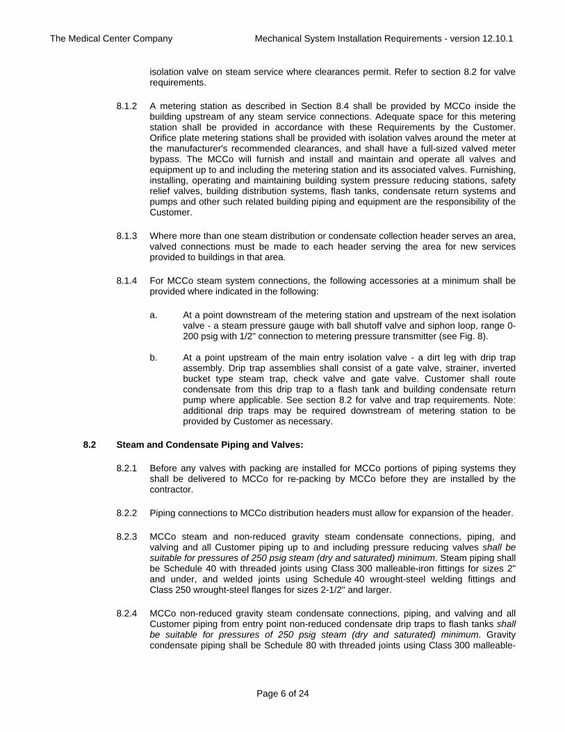
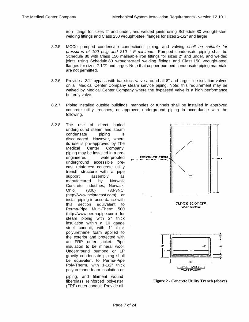
8.2.8 The use of direct buried underground steam and steam condensate piping is discouraged. However, where its use is pre-approved by The Medical Center Company, piping may be installed in a pre-engineered waterproofed underground accessible pre-cast reinforced concrete utility trench structure with a pipe support assembly as manufactured by Norwalk Concrete Industries, Norwalk, Ohio (800) 733-3NCI (http://www.nciprecast.com); or install piping in accordance with this section equivalent to Perma-Pipe Multi-Therm 500 (http://www.permapipe.com) for steam piping with 2" thick insulation within a 10 gauge steel conduit, with 1" thick polyurethane foam applied to the exterior and protected with an FRP outer jacket. Pipe insulation to be mineral wool. Underground pumped or LP gravity condensate piping shall be equivalent to Perma-Pipe Poly-Therm, with 1-1/2" thick polyurethane foam insulation on piping, and filament wound fiberglass reinforced polyester (FRP) outer conduit. Provide all
Figure 2 - Concrete Utility Trench (above)
The Medical Center Company Mechanical System Installation Requirements - version 12.10.1
Page 8 of 24
penetration and end seals for a moisture-proof installation. All underground piping shall be installed in accordance with applicable state and local codes and manufacturer's requirements. Installer's shall have been trained by the manufacturer's authorized installation specialist before installation begins.
Figure 3 - Perma-Pipe Poly-Therm (left) - Perma-Pipe Multi-Therm 500 (right)
8.2.9 Steam and gravity condensate valves on 2-1/2" and smaller MCCo service piping shall be gate type, 300# W.S.P., bronze, screwed pattern with rising stem, union bonnet, stainless steel seats, bronze single wedge disc. Valves shall conform to MSS SP-80 specifications. Valves shall be Crane, Hammond, Jenkins, or Stockham.
8.2.10 Steam and gravity condensate valves on 3" and larger MCCo service piping shall be high performance butterfly valves, rotary valve ANSI 300 lb class, double flange style, triple offset disc movement relative to the shaft. Body shall be carbon steel ASTM A216 Grade WCB integral flange style. Where gate valves are being replaced, utilize high performance butterfly valves with ANSI gate valve flange to flange dimensions wherever possible. Discs shall be stainless steel ASTM A351 Grade CF8M 316. Shaft shall be ASTM A564 type 630, one piece construction. Seat shall be resilient, non-flexing laminate metal seal composite of stainless steel and graphite retained such that centering movement is permitted. Shaft seal shall be graphite with four stud packing follower. Bearings shall be hardened with bearing seal retained in body. Include totally enclosed self-locking worm gear operator. The actuator mounting bracket shall be rigidly dowel pinned to the body to absorb torque loads and shall be centered by machined register between bracket and body. Gear operators shall be rated 1.5 times the maximum actual valve required torque. Valves shall have bi-directional zero leakage shut off for dead end service. Valves shall meet the requirements of API 607 Rev. 4 and API 6D. Valves shall be by Adams Valve model MAK300CS-SS-GO.
8.2.11 Condensate pumped discharge valves on piping 2-1/2”" and smaller shall be 150# W.S.P., bronze, screwed pattern with rising stem, union bonnet, single wedge disc. Valves shall conform to MSS SP-80. Valves shall be Crane, Hammond, Jenkins, or Stockham.
The Medical Center Company Mechanical System Installation Requirements - version 12.10.1
Page 9 of 24
8.2.12 Condensate pumped discharge valves on piping 3" and larger shall be high performance
butterfly valves with rotary valve ANSI 150 lb class, lug style, triple offset disc movement relative to the shaft. Body shall be carbon steel ASTM A216 Grade WCB, lug style, or integral flange style. Discs shall be stainless steel ASTM A351 Grade CF8M 316. Shaft shall be ASTM A564 type 630, one piece construction. Seat shall be resilient, non-flexing laminate metal seal composite of stainless steel and graphite retained such that centering movement is permitted. Shaft seal shall be graphite with four stud packing follower. Bearings shall be hardened with bearing seal retained in body. Include totally enclosed self-locking worm gear operator. The actuator mounting bracket shall be rigidly dowel pinned to the body to absorb torque loads and shall be centered by machined register between bracket and body. Gear operators shall be rated 1.5 times the maximum actual valve required torque. Valves higher than 7'-0" above adjacent access floor shall have chainwheel actuators with chains extending down to 5'-0" above adjacent floor in an accessible location. Valves shall have bi-directional zero leakage shut off for dead end service. Valves shall meet the requirements of API 607 Rev. 4 and API 6D. Valves shall be by Adams Valve model MAK-B6 150.
8.2.13 Gauge and metering isolation valves on 2-1/2" and smaller MCCo service piping shall be
as specified for gate valves. 8.2.14 Meter bypass valves 2" and smaller on MCCo service piping shall be globe type, 300#
W.S.P., bronze, screwed pattern with rising stem and union bonnet, and ANSI 420-S stainless steel tapered plug and seat. Valves shall conform to MSS SP-80 specifications. Valves shall be Crane, Hammond, Jenkins, or Stockham.
8.2.15 Meter bypass valves 2-1/2" and larger on MCCo service piping shall be globe type, 300#
W.S.P., cast steel, outside screw and yoke, flanged pattern, with bolted bonnet, rising stem, 410 stainless steel seat, stem, and disc. Valves shall conform to MSS SP-61 specifications. Valves shall be Crane, Jenkins, Hammond, Lunkenheimer, or Stockham.
8.2.16 Bar Stock valves shall be equal to Conbraco RP&C in carbon steel with globe
configuration, rated for use with wet or dry steam pressures to 250 psig minimum, with metal to metal seat and discs. Furnish with straight tee handle, female NPT connections.
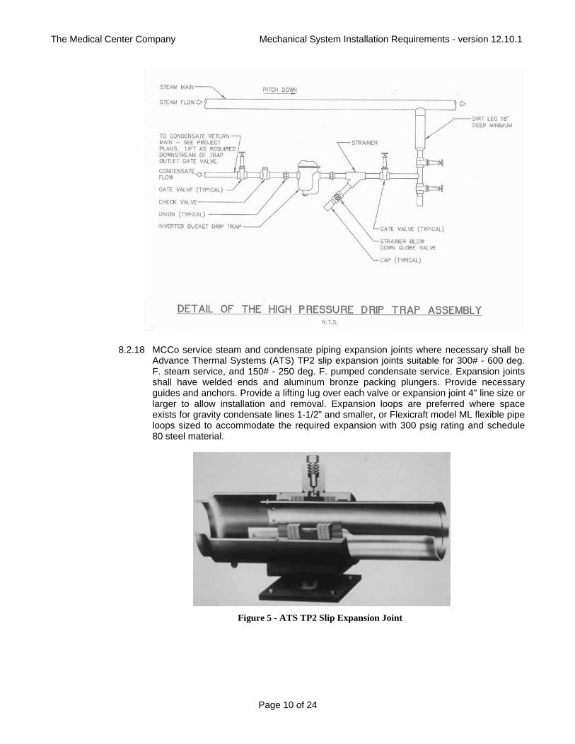
8.2.17 For MCCo service steam piping drip traps, provide inverted bucket traps at low point drip
locations with dirt leg upstream of trap, with body and cover constructed of cast iron or semi-steel, pressure rated for 250 psi, designed so internal parts are accessible without disturbing piping. Construct bucket of brass or stainless steel, and level mechanism of heat treated stainless steel, operating on knife edges for friction-free performance. Construct removable seats and plungers of heat treated stainless steel. Provide integral bi-metal auxiliary air vent in top of inverted bucket. Traps shall be Sarco "B" series. Trap assemblies shall be as per the following detail.
The Medical Center Company Mechanical System Installation Requirements - version 12.10.1
Page 10 of 24
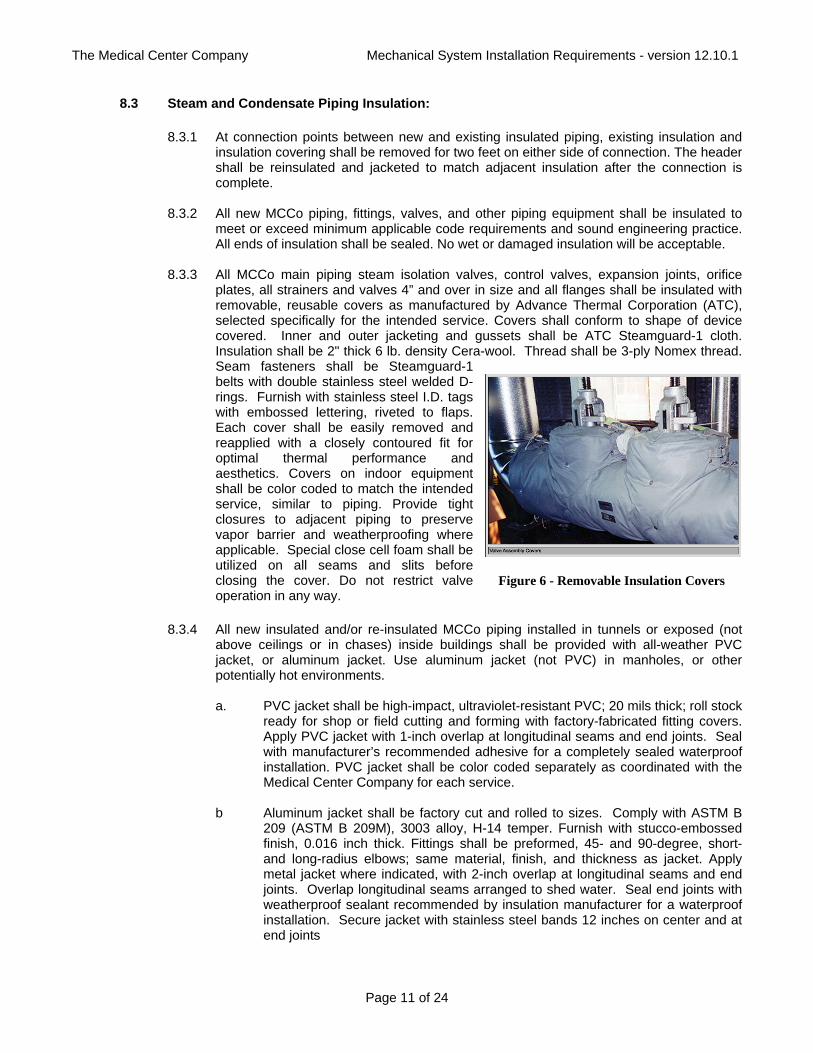
8.2.18 MCCo service steam and condensate piping expansion joints where necessary shall be Advance Thermal Systems (ATS) TP2 slip expansion joints suitable for 300# - 600 deg. F. steam service, and 150# - 250 deg. F. pumped condensate service. Expansion joints shall have welded ends and aluminum bronze packing plungers. Provide necessary guides and anchors. Provide a lifting lug over each valve or expansion joint 4" line size or larger to allow installation and removal. Expansion loops are preferred where space exists for gravity condensate lines 1-1/2” and smaller, or Flexicraft model ML flexible pipe loops sized to accommodate the required expansion with 300 psig rating and schedule 80 steel material.
Figure 5 - ATS TP2 Slip Expansion Joint
The Medical Center Company Mechanical System Installation Requirements - version 12.10.1
Page 11 of 24
8.3 Steam and Condensate Piping Insulation: 8.3.1 At connection points between new and existing insulated piping, existing insulation and
insulation covering shall be removed for two feet on either side of connection. The header shall be reinsulated and jacketed to match adjacent insulation after the connection is complete.
8.3.2 All new MCCo piping, fittings, valves, and other piping equipment shall be insulated to
meet or exceed minimum applicable code requirements and sound engineering practice. All ends of insulation shall be sealed. No wet or damaged insulation will be acceptable.
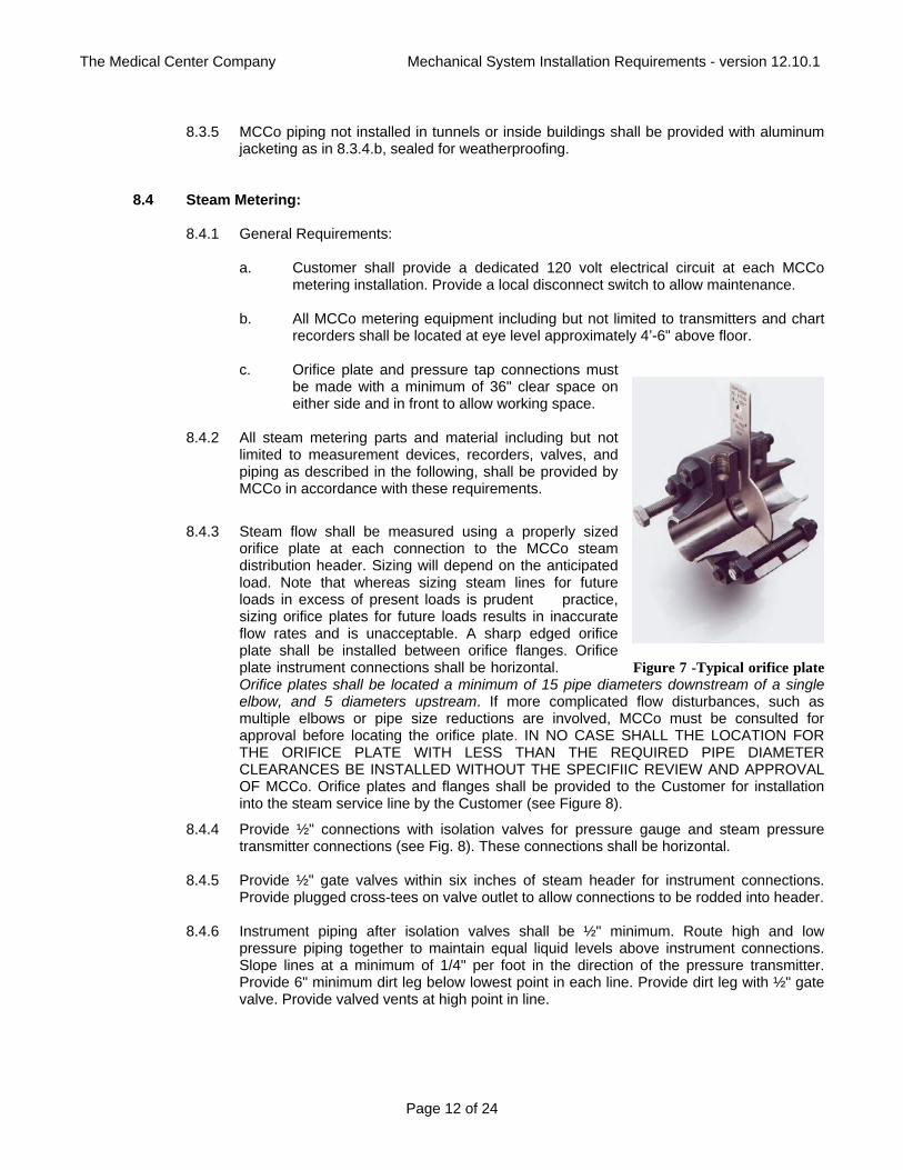
8.3.3 All MCCo main piping steam isolation valves, control valves, expansion joints, orifice
plates, all strainers and valves 4” and over in size and all flanges shall be insulated with removable, reusable covers as manufactured by Advance Thermal Corporation (ATC), selected specifically for the intended service. Covers shall conform to shape of device covered. Inner and outer jacketing and gussets shall be ATC Steamguard-1 cloth. Insulation shall be 2" thick 6 lb. density Cera-wool. Thread shall be 3-ply Nomex thread. Seam fasteners shall be Steamguard-1 belts with double stainless steel welded D-rings. Furnish with stainless steel I.D. tags with embossed lettering, riveted to flaps. Each cover shall be easily removed and reapplied with a closely contoured fit for optimal thermal performance and aesthetics. Covers on indoor equipment shall be color coded to match the intended service, similar to piping. Provide tight closures to adjacent piping to preserve vapor barrier and weatherproofing where applicable. Special close cell foam shall be utilized on all seams and slits before closing the cover. Do not restrict valve operation in any way.
8.3.4 All new insulated and/or re-insulated MCCo piping installed in tunnels or exposed (not
above ceilings or in chases) inside buildings shall be provided with all-weather PVC jacket, or aluminum jacket. Use aluminum jacket (not PVC) in manholes, or other potentially hot environments.
a. PVC jacket shall be high-impact, ultraviolet-resistant PVC; 20 mils thick; roll stock
ready for shop or field cutting and forming with factory-fabricated fitting covers. Apply PVC jacket with 1-inch overlap at longitudinal seams and end joints. Seal with manufacturer’s recommended adhesive for a completely sealed waterproof installation. PVC jacket shall be color coded separately as coordinated with the Medical Center Company for each service.
b Aluminum jacket shall be factory cut and rolled to sizes. Comply with ASTM B
209 (ASTM B 209M), 3003 alloy, H-14 temper. Furnish with stucco-embossed finish, 0.016 inch thick. Fittings shall be preformed, 45- and 90-degree, short- and long-radius elbows; same material, finish, and thickness as jacket. Apply metal jacket where indicated, with 2-inch overlap at longitudinal seams and end joints. Overlap longitudinal seams arranged to shed water. Seal end joints with weatherproof sealant recommended by insulation manufacturer for a waterproof installation. Secure jacket with stainless steel bands 12 inches on center and at end joints
Figure 6 - Removable Insulation Covers
The Medical Center Company Mechanical System Installation Requirements - version 12.10.1
Page 12 of 24
8.3.5 MCCo piping not installed in tunnels or inside buildings shall be provided with aluminum
jacketing as in 8.3.4.b, sealed for weatherproofing.
8.4 Steam Metering:
8.4.1 General Requirements:
a. Customer shall provide a dedicated 120 volt electrical circuit at each MCCo metering installation. Provide a local disconnect switch to allow maintenance.
b. All MCCo metering equipment including but not limited to transmitters and chart
recorders shall be located at eye level approximately 4’-6" above floor. c. Orifice plate and pressure tap connections must
be made with a minimum of 36" clear space on either side and in front to allow working space.
8.4.2 All steam metering parts and material including but not
limited to measurement devices, recorders, valves, and piping as described in the following, shall be provided by MCCo in accordance with these requirements.
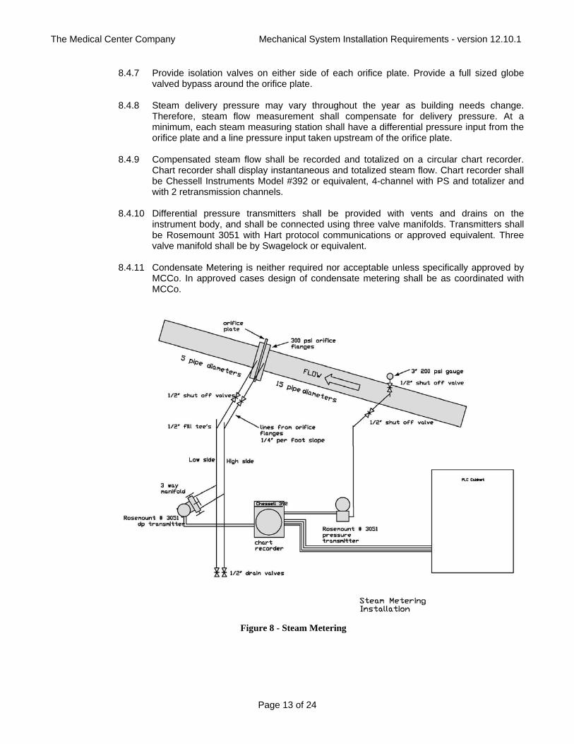
8.4.3 Steam flow shall be measured using a properly sized orifice plate at each connection to the MCCo steam distribution header. Sizing will depend on the anticipated load. Note that whereas sizing steam lines for future loads in excess of present loads is prudent practice, sizing orifice plates for future loads results in inaccurate flow rates and is unacceptable. A sharp edged orifice plate shall be installed between orifice flanges. Orifice plate instrument connections shall be horizontal. Figure 7 -Typical orifice plate Orifice plates shall be located a minimum of 15 pipe diameters downstream of a single elbow, and 5 diameters upstream. If more complicated flow disturbances, such as multiple elbows or pipe size reductions are involved, MCCo must be consulted for approval before locating the orifice plate. IN NO CASE SHALL THE LOCATION FOR THE ORIFICE PLATE WITH LESS THAN THE REQUIRED PIPE DIAMETER CLEARANCES BE INSTALLED WITHOUT THE SPECIFIIC REVIEW AND APPROVAL OF MCCo. Orifice plates and flanges shall be provided to the Customer for installation into the steam service line by the Customer (see Figure 8).
8.4.4 Provide ½" connections with isolation valves for pressure gauge and steam pressure transmitter connections (see Fig. 8). These connections shall be horizontal.
8.4.5 Provide ½" gate valves within six inches of steam header for instrument connections.
Provide plugged cross-tees on valve outlet to allow connections to be rodded into header. 8.4.6 Instrument piping after isolation valves shall be ½" minimum. Route high and low
pressure piping together to maintain equal liquid levels above instrument connections. Slope lines at a minimum of 1/4" per foot in the direction of the pressure transmitter. Provide 6" minimum dirt leg below lowest point in each line. Provide dirt leg with ½" gate valve. Provide valved vents at high point in line.
The Medical Center Company Mechanical System Installation Requirements - version 12.10.1
Page 13 of 24
8.4.7 Provide isolation valves on either side of each orifice plate. Provide a full sized globe valved bypass around the orifice plate.
8.4.8 Steam delivery pressure may vary throughout the year as building needs change.
Therefore, steam flow measurement shall compensate for delivery pressure. At a minimum, each steam measuring station shall have a differential pressure input from the orifice plate and a line pressure input taken upstream of the orifice plate.
8.4.9 Compensated steam flow shall be recorded and totalized on a circular chart recorder.
Chart recorder shall display instantaneous and totalized steam flow. Chart recorder shall be Chessell Instruments Model #392 or equivalent, 4-channel with PS and totalizer and with 2 retransmission channels.
8.4.10 Differential pressure transmitters shall be provided with vents and drains on the
instrument body, and shall be connected using three valve manifolds. Transmitters shall be Rosemount 3051 with Hart protocol communications or approved equivalent. Three valve manifold shall be by Swagelock or equivalent.
8.4.11 Condensate Metering is neither required nor acceptable unless specifically approved by
MCCo. In approved cases design of condensate metering shall be as coordinated with MCCo.
Figure 8 - Steam Metering
The Medical Center Company Mechanical System Installation Requirements - version 12.10.1
Page 14 of 24
8.5 Steam and Condensate Equipment Design and Selection: 8.5.1 Condensate Pumping Stations:
a. Tests of the condensate header pressure at the connection point must be made to determine the head requirements of the condensate pumps. Review pressures with MCCo for seasonal changes, and planned modifications to mains. The Medical Center Company will provide Customers with anticipated pressure requirements from the point of connection to MCCo's pumped condensate return header back to the boiler plant.
b. In order to prevent excess flow in pumped condensate mains, all condensate
stations must be sized to return condensate to the Medical Center Company collection headers at a peak rate no greater than 200% of the steam flow rate to the facility at actual operating conditions. Customers must oversize building condensate pump receivers if necessary to accomplish this requirement.
c. The maximum condensate return temperature into the pressurized service mains
is 212 deg. F. Provision must be made for flashing or otherwise cooling steam at higher temperatures in order to reduce the possibility of flashing and hammering within the return headers.
d. For MCCo provided pumps, MCCo's contractor shall provide and for Customer
provided pumps, Customer shall provide at a minimum a non-slam check valve, combination isolation/throttling globe, butterfly or ball valve and pressure gauge at each condensate pump discharge. Securely support condensate pump discharge piping. Extend receiver vents to the outdoors in an approved manner. Provide a drain upstream of the condensate pumps with provisions for diverting condensate into a sewer on a temporary basis if the pumped condensate main is being serviced. Drains shall be gravity condensate main line sized up to 2" size, and 2" above. Terminate emergency drain valve with hose thread and cap. Do not route condensate drains into PVC material sewer drains.
e. Provide a ¾" valved connection with hose thread at condensate receiver
(preferred) or pump discharge for water testing. f. Condensate pumping stations
provided by The MCCo shall be manufactured by Gerow Equipment Company, Cleveland, Ohio (216) 761-4900. Pumps shall be type CEH Sterling SIHI side channel multi-stage turbine design with stuffing boxes, maximum 2 feet NPSH requirement, and bronze fitted, with flexible coupling guard. Furnish pumps on a painted steel or stainless steel channel skid-mounted duplex arrangement with factory wired stainless steel float switches and mechanical alternator to provide sequencing of pumps and standby of second pump on high condensate level. Furnish factory Figure 9 - Typical Flash Tank
The Medical Center Company Mechanical System Installation Requirements - version 12.10.1
Page 15 of 24
wired NEMA 4X control panel with main disconnect, alternator, fused magnetic starters, overload reset pushbuttons, pump selector switches, pump run pilot lights, control transformer, running time meters. Furnish high level alarm contacts. Factory wire pump motors. Furnish stainless steel receiver. Furnish inlet basket strainer. Furnish water level gauge with shutoff valves for receivers. Furnish thermometer on receiver. All metal components shall be factory painted.
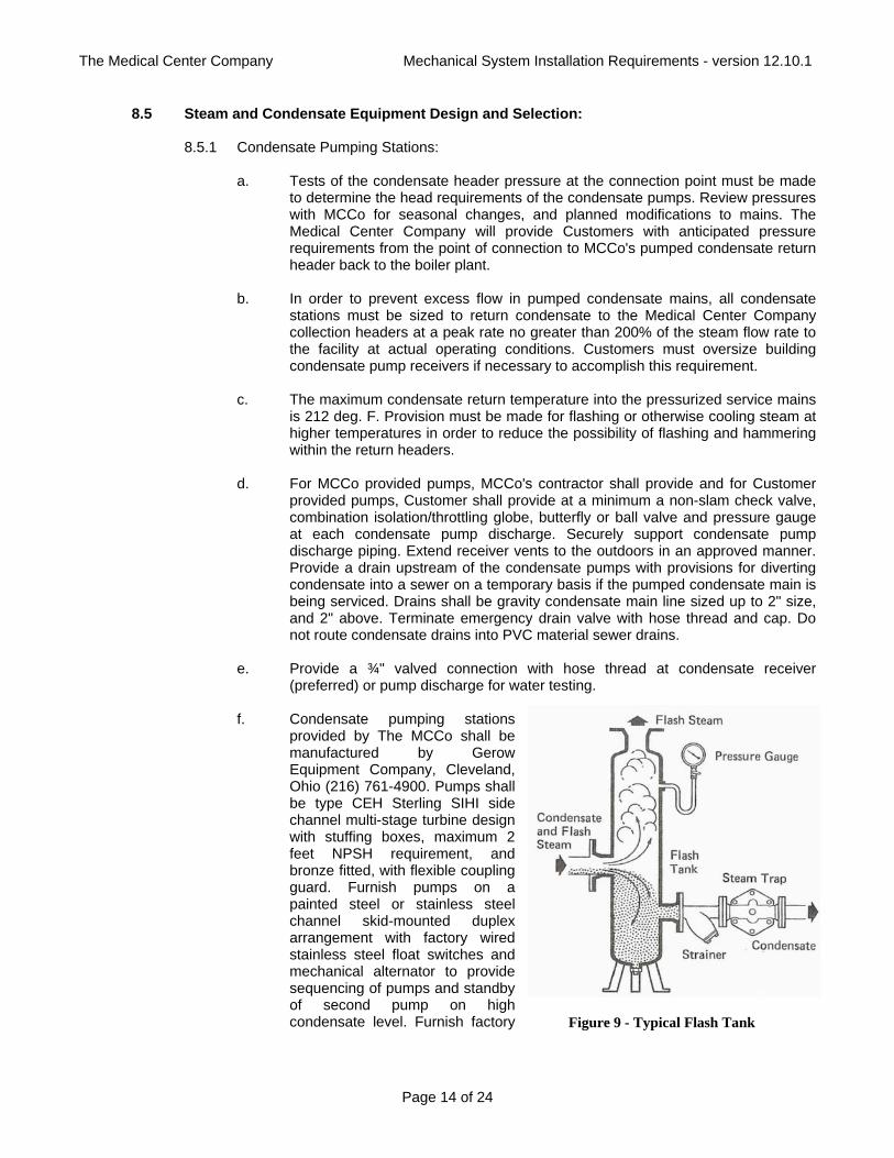
8.5.2 Flash Tanks: Wherever condensate is being returned upstream of condensate pumping
stations at temperature in excess of 212 deg. F., provide flash tanks vented to atmospheric pressure sized and located in accordance with good engineering practice to lower the steam pressure to near atmospheric, thus cooling it to 212 F or below prior to being pumped back into the condensate return system (see Figure 9).
9. Chilled Water Systems: 9.1 Chilled Water Service Connections:
9.1.1 An isolation valve shall be provided within six feet of any service connection to the MCCo chilled water distribution header. These isolation valves shall be accessible and operable from the utility tunnel where possible, and where not possible the valves shall be direct buried valves. Isolation valves shall also be installed in the serviced building within six feet of the building entry point. Refer to section 9.2 for valve requirements. Provide the following accessories on the building side of these isolation valves located within the building:
a. Pressure gauges with ball shutoff valves. Gauges shall be accessible and readable from ground level. Gauges for hydronic piping applications shall be filled with silicone liquid, rated for the intended use.
b. Automatic air vents with ball shutoff valves and with manual bypass ball valve
vent with caps located at high points. c. 2" minimum manual drain connection on each line with threaded drain caps or
plugs located at low points. d. 9" thermometers installed in heavy-duty 316 stainless steel thermowells, 2-1/2"
minimum insertion. Thermowells shall be provided with lagging extensions so that insulation does not cover top of well. Where thermometers are not accessible and readable from ground level, provide remotely mounted 4-1/2" diameter dial-type thermometers located to be visible from ground level.
9.1.2 MCCo metering equipment (as described in section 9.4) shall be provided inside the building downstream of the entry point isolation valves and upstream of primary/secondary bridges and any building connections.
9.1.3 Unless specifically permitted otherwise by MCCo, Customer shall provide for each chilled water service connection usage a primary/secondary piping and bridge arrangement on the user side of the connection similar to that shown in Figure 15. Material, installation, equipment control, maintenance and costs of operation of this bridge and pumping shall be by the Customer. Bridge control valve may be line sized modulating three-way butterfly valves with actuators selected for smooth modulating action throughout their range with minimal pressure drops. Pressure drop allowance across the bridge on the primary side by MCCo shall be 5 psig. Primary/secondary control valve actuators must be
The Medical Center Company Mechanical System Installation Requirements - version 12.10.1
Page 16 of 24
selected to close off against MCCo head pressures at the location connected - typically 100 psig (contact MCCo for this information which will depend on location). The primary/secondary control valve shall be automatically modulated through the user's local control system as required to maintain a chilled water setpoint to the building on the secondary pumping side of no less than 45oF (46oF is preferred). MCCo water temperature supply to the bridge will typically be lower than this temperature. Return chilled water temperature from buildings shall be designed for no less than 61oF. Control valve type and pump speed control if any on the Customer's secondary side is at the discretion of the Customer, but users are advised that energy conservation opportunities may exist on larger systems through the use of variable speed pumping and two-way full shut-off modulating control valves. Customer shall provide a temperature sensor in the common chilled water supply on the building side of the bridge for 3-way primary/secondary valve control, and a temperature sensor on the common return line back to the service return for monitoring. Customer shall provide a check valve in the service supply to return at the bridge where indicated to prevent service supply water from slipping back to service return without going through the bridge. Customer shall provide thermometers and pressure gauges around bridge valve as indicated in Figures 15. Customer shall provide a 4-20mA valve positioner feedback signal from the primary/secondary 3-way valve, and 4-20mA secondary chilled water supply and return temperature output signals for connection to and routing back to the local MCCo control panel by MCCo for remote system monitoring purposes.
9.2 Chilled Water Piping, Valves and Strainers:
9.2.1 All chilled water system connections, piping, fittings and valving and equipment connected to the MCCo distribution system unless otherwise indicated by MCCo shall be suitable for class 150 psi water minimum working pressure.
9.2.2 MCCo chilled Water piping 2" and smaller shall be fabricated from Scheduled 40 black steel pipe, cast or malleable iron fittings and threaded joints or copper piping, wrought copper fittings and solder joints, separated from steel piping by dielectric materials. MCCo chilled Water piping 2-1/2" and larger shall be fabricated from Schedule 40 steel pipe with Schedule 40 steel weld neck fittings and welded joints (standard weight pipe and fittings above 10" size).
9.2.3 Before any valves with packing on MCCo piping are installed they shall be delivered to the Medical Center Company for re-packing by the Medical Center Company before they are installed by the contractor.
9.2.4 For accessible MCCo piping Chilled Water valves 2" and smaller, utilize ball valves. Ball Valves 2" and smaller shall be 150 psi saturated steam rated; 600 psi non-shock cold water, oil or gas rated; two-piece body; chrome plated ball; blowout proof stem; reinforced TFE seats; full port design in all sizes; bronze or brass body; all 316 stainless steel trim on valves used for steam service; screwed/soldered pattern. Valves shall be equal to Apollo 77. Valves shall have an extended handle which provides valve packing maintenance without disturbing the insulation. Air vents and drain valves for Chilled Water lines shall be bronze, screwed/soldered pattern ball valves with a 3/4" male hose thread adaptor. The hose thread adaptor shall have a metal cap with a rubber washer. Air vents and drain valves shall be equal to Apollo 70.
9.2.5 For MCCo supplied piping Chilled Water valves for buried applications use underground type high performance butterfly valves (see 9.2.7.1). Provide valve box with cover, extension to grade and base with “MCCo” impression on cap. All components installed underground to be coated for underground service. For non-buried Chilled Water valves
The Medical Center Company Mechanical System Installation Requirements - version 12.10.1
Page 17 of 24
2-1/2" and larger in MCCo supplied piping where valves are used in an application which isolates a building or device from the Primary Medical Center Company Chilled or Condenser Water distribution system, use "high performance" butterfly valves (see 9.2.7.1). For non-buried Chilled Water valves 2-1/2" and larger in MCCo supplied piping where valves are NOT used in an application that isolates a building or device from the primary Medical Center Company Chilled or Condenser Water distribution system, use "standard" butterfly valves (see 9.2.7.2).
9.2.6 Butterfly valves utilized in MCCo piping may be supplied by MCCo at MCCo’s option at
MCCo’s Powerhouse Plant for pick-up there and installation in system by Contractor. Review with MCCo.
9.2.7 Butterfly Valves:
9.2.7.1 High performance butterfly valves, 3" and larger shall be shall be rotary valve ANSI 150 lb class, lug style, triple offset disc movement relative to the shaft. Body shall be carbon steel ASTM A216 Grade WCB, lug style, or integral flange style. Discs shall be stainless steel ASTM A351 Grade CF8M 316. Shaft shall be ASTM A564 type 630, one piece construction. Seat shall be resilient, non-flexing laminate metal seal composite of stainless steel and graphite retained such that centering movement is permitted. Shaft seal shall be graphite with four stud packing follower. Bearings shall be hardened with bearing seal retained in body. Include totally enclosed self-locking worm gear operator. The actuator mounting bracket shall be rigidly dowel pinned to the body to absorb torque loads and shall be centered by machined register between bracket and body. Gear operators shall be rated 1.5 times the maximum actual valve required torque. Valves higher than 7'-0" above adjacent access floor shall have chainwheel actuators with chains extending down to 5'-0" above adjacent floor in an accessible location. Valves shall have bi-directional zero leakage shut off for dead end service. Valves shall meet the requirements of API 607 Rev. 4 and API 6D. Valves shall be by Adams Valve model MAK-B6 150.
9.2.7.2 Standard butterfly valves, 2-1/2" and larger shall be full lug style ductile iron body
(cast iron is not acceptable) with extended neck for insulating designed for bubble tight, dead end bi-directional shut-off without blind flanges at 200 psi for sizes through 12" and 150 psi for larger sizes. Discs shall be aluminum bronze and shall be attached to a 416 stainless steel stem. Seat material shall be phenolic backed and reinforced with cartridge or metal and shall be EPDM (EPT) suitable for 275 deg. F. Seat and backing ring shall be easily replaceable in the field. Bushings shall be PTFE, and O-ring where applicable shall be Buna-N. Valves 6" and smaller shall have lever operators. Larger valves shall have gear operators with hand wheels. Gear operators shall be rated 1.5 times the maximum actual valve required torque. Valves 4" and larger higher than 7'-0" above adjacent access floor shall have chainwheel actuators with chains extending down to 5'-0" above adjacent floor in an accessible location. Valves shall be Bray, Center Line, Crane, Jenkins, Keystone, Stockham or Xomox.
9.2.8 Strainers: All MCCo and Customer building pumps, coils, and heat exchangers of any
type utilizing Medical Center Company chilled water shall be protected with inlet strainers or suction diffusers.
9.2.9 Where specifically requested by MCCo, underground direct buried valves used on MCCo chilled water systems shall be quarter turn resilient seated ball valves. Valves shall be carbon steel body, flanged end, full bore, class 150, with AISI 316 stainless steel ball and stem, Teflon seat, seal for chilled water application and flexible graphite packing. Valves
The Medical Center Company Mechanical System Installation Requirements - version 12.10.1
Page 18 of 24
through 10" shall be Watts CF1800150T-316-M1 (http://www.wattsind.com). Ball valves 12" and larger shall be KF Industries Series P-199-12129 (http://www.kfvalves.com). Provide underground direct buried valve operators with grey iron casting gearcase and cover; solid top cover without position indicator; aluminum bronze wormgear quadrant; hardened steel worm; stainless steel worm shaft/input shaft; synthetic rubber 0-rings on the input and output bearing journals; lip seal on the input shaft; as a minimum, oil impregnated bronze or needle bearing type input shaft bearings; two (2) end of travel adjustable mechanical stops; filled for life No. 2 grease lubricant; external finish to be a minimum of red oxide primer; gear operators shall be rated 1.5 times the maximum actual valve required torque; to be provided with a 2" square input drive nut requiring no more than 60 lbs of effort to seat/unseat the valve; spur gear attachment are to be utilized where necessary; removable splined drive nut to be bored and keyed to match the valve shaft or coupling driver. Provide valve box with cover, extension to grade and base. All components installed underground to be coated for underground service.
9.2.10 Piping installed outside of buildings, manholes and tunnels shall be installed in utility
trenches, or approved underground piping in accordance with the following.
9.2.11 The use of direct buried underground chilled water piping is discouraged. However, where its use is pre-approved by MCCo, piping may be installed in a pre-engineered waterproofed underground accessible pre-cast reinforced concrete utility trench structure with a pipe support assembly as manufactured by Norwalk Concrete Industries, Norwalk, Ohio (800) 733-3NCI (http://www.nciprecast.com); or install piping in accordance with this section equivalent to Perma-Pipe Poly-Therm (see Figure 3), with 1-1/2" thick polyurethane foam insulation on piping, and filament wound fiberglass reinforced polyester (FRP) outer conduit. Provide all penetrations and end seals for a moisture-proof installation. All underground piping shall be installed in accordance with state and local codes and manufacturer's requirements. Installers shall have been trained by the manufacturer's authorized installation specialist before installation begins. All piping installations shall be field measured prior to ordering for length and fitting verification.
9.3 Chilled Water Piping Insulation: 9.3.1 At connection points between new and existing insulated piping, existing insulation and
insulation covering shall be removed for two feet on either side of connection. The header shall be reinsulated and jacketed to match adjacent insulation after the connection is complete.
9.3.2 All new MCCo chilled water piping, fittings, valves, and other piping equipment shall be
insulated to meet or exceed applicable minimum code requirements and sound engineering practice. All ends of insulation shall be sealed. No wet or damaged insulation will be acceptable.
9.3.3 All MCCo chilled water piping valves, control valves, expansion joints, meters, chiller
evaporator water boxes, pump casings all strainers, suction diffusers and valves 4” and over in size and flanges of all sizes shall be insulated with removable, reusable covers as manufactured by Advance Thermal Corporation (ATC), selected specifically for the intended service. Covers shall be specifically designed for the cold intended service and shall conform to shape of the equipment covered without sagging. Inner and outer jacketing shall be minimum 17 oz./sq. yd. Teflon coated fiberglass cloth. Insulation core shall be 2" thick 6 lb. density ET blanket fiberglass. Seam closures shall be pure Teflon thread. Both fire retardant straps and hook and loop fasteners shall be used for tightly securing the blankets. To prevent insulation from shifting within the cover quilt pins of 12 gauge stainless steel shall be utilized. The quilt pins shall not penetrate the inner face of
The Medical Center Company Mechanical System Installation Requirements - version 12.10.1
Page 19 of 24
the covers. Furnish with 304 stainless steel I.D. tags with embossed lettering, riveted to flaps. Outdoor covers shall be designed for outdoor use to withstand the weather and maintain the required vapor barrier and thermal insulation characteristics. Covers on indoor equipment shall be color coded to match the intended service, similar to piping. Provide tight closures to adjacent piping to preserve vapor barrier and weatherproofing where applicable. Special close cell foam shall be utilized on all seams and slits before closing the cover. Do not restrict valve operation in any way
9.3.4 All new insulated and/or re-insulated MCCo chilled water piping installed in tunnels or
exposed (not above ceilings or in chases) inside buildings shall be provided with all-weather PVC jacket, or aluminum jacket. Use aluminum jacket (not PVC) in manholes, or other potentially hot environments.
a. PVC jacket shall be high-impact, ultraviolet-resistant PVC; 20 mils thick; roll stock
ready for shop or field cutting and forming with factory-fabricated fitting covers. Apply PVC jacket with 1-inch overlap at longitudinal seams and end joints. Seal with manufacturer’s recommended adhesive for a completely sealed waterproof installation. PVC jacket shall be color coded separately as coordinated with The Medical Center Company for each service.
b Aluminum jacket shall be factory cut and rolled to sizes. Comply with ASTM B
209 (ASTM B 209M), 3003 alloy, H-14 temper. Furnish with stucco-embossed finish, 0.016 inch thick. Fittings shall be preformed, 45- and 90-degree, short- and long-radius elbows; same material, finish, and thickness as jacket. Apply metal jacket where indicated, with 2-inch overlap at longitudinal seams and end joints. Overlap longitudinal seams arranged to shed water. Seal end joints with weatherproof sealant recommended by insulation manufacturer for a waterproof installation. Secure jacket with stainless steel bands 12 inches on center and at end joints.
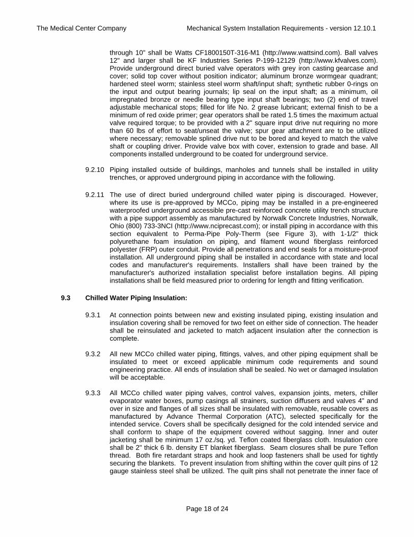
9.3.5 Exterior insulated MCCo piping not installed in tunnels or inside buildings shall be
provided with aluminum jacketing as in 9.3.3.b, sealed for weatherproofing.
Figure 11 - Aluminum Jacket
9.4 Chilled Water Metering:
9.4.1 General Requirements: Customer shall provide a dedicated 120 volt electrical circuit at each metering device installation with a local disconnect switch to allow maintenance. Power wiring to MCCo furnished devices shall be as indicated in Figure 15. Financial responsibility for installation and connection of MCCo control devices shall generally be
The Medical Center Company Mechanical System Installation Requirements - version 12.10.1
Page 20 of 24
by MCCo. However, the typical arrangement and format for showing this work is that the Customer shall have their control wiring and control components on their project bid documents shown to be under their Base Bid, and the control wiring and installation on Figure 15 shown to be furnished by MCCo will be installed and wired by the Customers contractor and included in the project bids as a separate Bid Alternate so that the cost allocation can be determined between the Customer and MCCo. Final control wiring connections as indicted in Figure 15 shall be by MCCo.
9.4.2 Chilled water flow to each building shall be monitored by the Medical Center Company SCADA system. Final connection of output signal from MCCo PLC Control Panels to SCADA system shall be by The Medical Center Company. All parts and material including but not limited to measurement devices, meters, valves, and piping as described in the following, shall be provided by MCCo as indicated in Figure 15.
9.4.3 MCCo's contractor shall provide twisted shielded 18-22 gauge wiring between the field devices and the MCCo flow computer and PLC Control Panel. All control wiring shall be in EMT raceway, ½" minimum trade size. Connection to devices shall be made using flexible conduit so that device may be withdrawn without disturbing connections.
9.4.4 MCCo shall provide RTD temperature probes for field installation in supply and return lines to measure system differential temperature. RTD shall be with a spring-loaded sheath and an oversized head suitable for transmitter mounting. RTD shall be three-wire type, temperature coefficient shall be .00385 ohms/ohm/ °C. RTD shall be securely mounted into thermowell. RTD sensors shall be RAM sensors or equivalent.
9.4.5 Temperature probes shall be installed in heavy-duty 316 stainless steel thermowells, 2-1/2" minimum insertion provided by MCCo. Thermowells shall be provided with lagging extensions so that insulation does not cover top of well. Thermowells shall be suitable for ¼" diameter RTD elements.
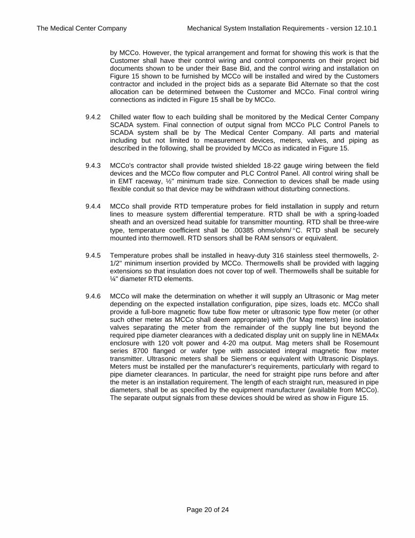
9.4.6 MCCo will make the determination on whether it will supply an Ultrasonic or Mag meter depending on the expected installation configuration, pipe sizes, loads etc. MCCo shall provide a full-bore magnetic flow tube flow meter or ultrasonic type flow meter (or other such other meter as MCCo shall deem appropriate) with (for Mag meters) line isolation valves separating the meter from the remainder of the supply line but beyond the required pipe diameter clearances with a dedicated display unit on supply line in NEMA4x enclosure with 120 volt power and 4-20 ma output. Mag meters shall be Rosemount series 8700 flanged or wafer type with associated integral magnetic flow meter transmitter. Ultrasonic meters shall be Siemens or equivalent with Ultrasonic Displays. Meters must be installed per the manufacturer’s requirements, particularly with regard to pipe diameter clearances. In particular, the need for straight pipe runs before and after the meter is an installation requirement. The length of each straight run, measured in pipe diameters, shall be as specified by the equipment manufacturer (available from MCCo). The separate output signals from these devices should be wired as show in Figure 15.
The Medical Center Company Mechanical System Installation Requirements - version 12.10.1
Page 21 of 24
Figure 12 – Ultrasonic Flow Meter with Ultrasonic Display
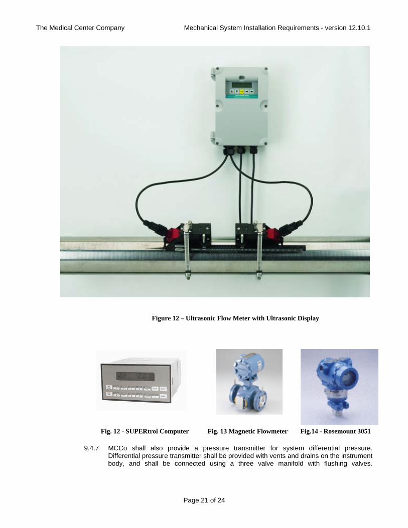
Fig. 12 - SUPERtrol Computer Fig. 13 Magnetic Flowmeter Fig.14 - Rosemount 3051
9.4.7 MCCo shall also provide a pressure transmitter for system differential pressure. Differential pressure transmitter shall be provided with vents and drains on the instrument body, and shall be connected using a three valve manifold with flushing valves.
The Medical Center Company Mechanical System Installation Requirements - version 12.10.1
Page 22 of 24
Transmitter shall be Rosemount 3051 with Hart Protocol communication or approved equivalent. Three valve manifold by Swagelock. Signals from these devices should be wired as shown in Figures 15. See Figure 8 for mounting.
Figure 15 - Chilled Water Bridge Arrangement & Controls
9.5 Chilled Water Equipment Design and Selection:
9.5.1 New and/or replacement chilled water coils shall be selected for a minimum leaving chilled water temperature 61°F (see 9.1.3 for bridge requirements). Chilled water supply temperature to the building from the Medical Center Company distribution system is approximately 44°F but will vary somewhat seasonally. Users shall select chilled water equipment for the building on the secondary side of the primary/secondary bridge at no less than 45°F entering chilled water temperatures, and 46 °F is preferred.
The Medical Center Company Mechanical System Installation Requirements - version 12.10.1
Page 23 of 24
Building return temperature design shall be for 61°F leaving building back to Medical Center Company system.
9.5.2 Maximum chilled water supply pressure is 150 psi. Install no pressure relief valves in
chilled water distribution systems with setpoints lower than 150 psig. If it is necessary to use local building pressure relief valves, adjustable setpoint relief valves are recommended.
9.5.3 For unusual cases where buildings due to their location on the system or low pressure
drop are permitted by MCCo to be direct connected with no primary/secondary bridge, MCCo can and does provide some motive force to circulate chilled water. Building distribution system in these case shall be designed so that the pressure drop in all piping, coils, and control valves is no more than 26 psi. If pumps are provided in buildings they shall be configured so as to not apply additional backpressure to MCCo's return chilled water system. Also, care should be taken to prevent the combined dynamic pressures of pumps from exceeding the maximum pressure rating of connected piping and equipment. MCCo must pre-approve any building connection arrangement.
9.5.4 Customer cooling coil control valves for direct connected buildings shall be two-way
modulating industrial control valves with a tight shut-off against a minimum shut-off differential pressure as defined by MCCo (typically 100 psi). This pressure may depend on the location in the system and users should confirm the pressure requirements with the Medical Center Company before selecting valves. Failure to select valve actuators with proper shut-off pressure capabilities may result in leakage through valves and/or valve failures.
9.5.5 Do not install permanently connected make-up water connections to the chilled water
system. Water is made up at MCCo's chilled water plants at strictly regulated pressures. 9.5.6 Buildings with chilled water piping or components higher than 130 feet above grade level
at The Medical Center Company's Powerhouse cannot be directly connected to the chilled water system due to make-up pressure limitations. Contact the MCCo for separation heat exchanger requirements and strategies.
9.6 Chilled Water System Water Quality and Specialized Connections:
9.6.1 The Medical Center Company maintains sand filters and packaged filtration systems which are intended to assist in reducing entrained solids content within the distribution piping. However, corrosion and scale in the distribution system may result in solids being introduced to the system and carried throughout the piping before they can be removed. Occasionally solids may accumulate in lower velocity areas of piping and may be more difficult to remove. Typically the solids content in the chilled water distribution system will be at or below values typical for a similarly large distribution system. However, care must be taken by Customers to protect sensitive equipment which may be damaged by entrained solids. Pumps, coils, heat exchangers and similar equipment shall be protected with a minimum of an inlet strainer or suction diffuser.
9.6.2 Where sensitive equipment is connected to the chilled water distribution system which
may be affected by entrained solid particles less than 75 µ in size it is recommended that the Customer install a protective in-line strainer and filter to protect the equipment.
9.6.2 Where chilled water is connected to critical equipment as a heat rejection source, the
connection methodology must be reviewed with The Medical Center Company. Connections to chilled water supply will generally be in the 42 F to 45 F range. Connections to the return will be higher in temperature but a local pump may be required.
The Medical Center Company Mechanical System Installation Requirements - version 12.10.1
Page 24 of 24
For reliability it is recommended that a valved back-up connection be made to the local domestic water system, Note that approved backflow prevention methods must be used. Note that chilled water system pressures may exceed 150 psig pressure, depending on where connections are made in the system.
END OF MECHANICAL SYSTEM INSTALLATION REQUIREMENTS