Embed Size (px)
Citation preview
Für die Einzelleuchtenüberwachung in Verbindung mit D.E.R.-Controller müssen individuelle Leuchtenadressen eingestellt werden. Die Einstellung erfolgt über die Adressschalter auf der Steuerplatine.
z.B. Adresse 2 eingestellt.
Adresse
Zehner Einer
0
891
3 45
6
7
2
0
891
3 45
6
7
2
Die Steuerung und Programmierung der Leuchte erfolgt über den D.E.R-Controller.
Die Steuerung der Leuchte erfolgt über die optionalen Kontakte! [Klemmen 0 (+8V), 1, 2, 3]
8V Steuerspannung nur zur Steuerung einer einzelnen Leuchte verwenden!
Mit den Adressschaltern auf der Platine werden die Muster (Funktionen)der Leuchte eingestellt. Die Adresse ist der beilie-genden Mustertabelle zu entnehmen.
z.B. Muster 2 eingestellt.
Adresse
Zehner Einer
0
891
3 45
6
7
2
089
1
3 45
6
7
2
Adressierung bei 24V-VersorgungsgerätJede Leuchte hat eine individuelle vom Werk vergebene 5-stelli-ge ID-Nummer. Diese ID-Nummer ist auf der Leuchte vermerkt.Für die Einzelüberwachung in Verbindung mit dem INOTEC CLS-System ist die angegebene ID-Nummer im Steuerteil einzuge-ben und einer logischen Adresse von 1 bis 20 zuzuordnen.
Maximale Leitungslänge: 10m!Maximale Leitungslänge: 10m!
Die Steuerung und Programmierung der Leuchte erfolgt über das TFT-Steuerteil der Zentralbatterieanlage CPS 220/64.
Adressierung bei 24V-VersorgungsgerätJede Leuchte hat eine individuelle vom Werk vergebene 5-stellige ID-Nummer. Diese ID-Nummer ist auf der Leuchte vermerkt.Für die Einzelüberwachung ist die angegebe-ne ID-Nummer im TFT-Steuerteil einzugeben.
Die Steuerung der Leuchte erfolgt über die optionalen Kontakte! [Klemmen 0 (+8V), 1, 2, 3]
8V Steuerspannung nur zur Steuerung einer einzelnen Leuchte verwenden
Mit den Adressschaltern auf der Platine werden die Muster (Funktionen) der Leuchte eingestellt. Die Adresse ist der beilie-genden Mustertabelle zu entnehmen.
z.B. Muster 2 eingestellt.
Adresse
Zehner Einer
0
891
3 45
6
7
2
0
891
3 45
6
7
2
Für die Einzelleuchtenüberwachung in Verbindung mit 230V-D.E.R.-Einschub müssen individuelle Leuchtenadressen innerhalb eines Stromkreises eingestellt werden. Die Einstellung erfolgt über die Adressschalter auf der Steuerplatine.
z.B. Adresse 2 eingestellt.
Adresse
Zehner Einer
0
891
3 45
6
7
2
0
891
3 45
6
7
2
Die Steuerung und Programmierung der Leuchte erfolgt über das TFT-Steuerteil der Zentralbatterieanlage CPS 220/64.
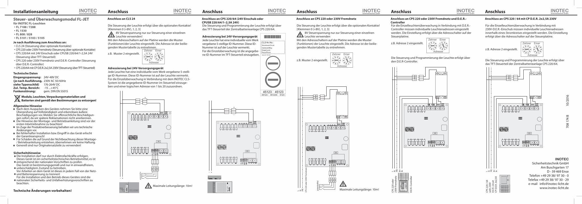
Installationsanleitung
Steuer- und Überwachungsmodul FL-JETfür INOTEC FL-Leuchten• FL 7188 / 7288 • FL 1530• FL 808 / 828• FL 5101 / 5103 / 5105
Technische DatenEingangsspannung:(je nach Ausführung, siehe Typenschild)
24V-48V DC230V AC 50/60Hz176-264V DC
Zul. Temp. Bereich: -15 ...+45°CFunkenstörung: gem. DIN EN 55015
Anschluss Anschluss Anschluss Anschluss Anschluss
Allgemeine HinweiseNach dem Auspacken des Gerätes nehmen Sie bitte eine Überprüfung auf Vollständigkeit und erkennbare äußere Beschädigungen vor. Melden Sie offensichtliche Beschädigun-gen sofort, da wir spätere Reklamationen nicht anerkennen.Die Hinweise der Montage- und Betriebsanleitung sind vor der ersten Inbetriebnahme zu beachten!Im Zuge der Produktverbesserung behalten wir uns technische Änderungen vor. Bei fehlerhafter Installation bzw. Eingriff in das Gerät erlischt der Garantieanspruch! Für Schäden die auf Grund der Nichtbeachtung dieser Montage- / Betriebsanleitung entstehen, übernehmen wir keine Haftung.Generell sind nur Originalersatzteile zu verwenden!
Module, Leuchten, Verpackungsmaterialien und Batterien sind gemäß den Bestimmungen zu entsorgen!
SicherheitshinweiseDie Installation darf nur durch Elektrofachkräfte erfolgen.Dieses Gerät ist ein sicherheitstechnisches Betriebsmittel, es ist entsprechend der nationalen Vorschriften zu prüfen. Das Gerät ist bestimmungsgemäß und nur in einwandfreiem, unbeschädigtem Zustand zu betreiben.Vor Arbeiten an dem Gerät ist dieses in jedem Fall von der Netz- und Batteriespannung zu trennen!Für die Installation und den Betrieb dieses Gerätes sind die nationalen Sicherheits- und Unfallverhütungsvorschriften zu beachten.
Technische Änderungen vorbehalten!
Je nach Ausführung zum Anschluss an:• CLS 24 (Steuerung über optionale Kontakte)• CPS 220 oder 230V Fremdnetz (Steuerung über optionale Kontakte)• CPS 220/64 mit 24V Einschub oder CPUSB 220/64/1-2,5A 24V
(Steuerung über TFT-Steuerteil)• CPS 220 oder 230V Fremdnetz und D.E.R.-Controller (Steuerung
über D.E.R.-Controller)• CPS 220/64 mit CP D.E.R. 2x2,5A 230V (Steuerung über TFT-Steuerteil)
+-
+
-
0 1 2 3
321+
GND 24V48V
INO
TE
C
12
34
56
78
91
01
11
21
31
41
51
61
71
81
92
0
SK
1S
K 2
SK
3S
K 4
Ein
/On
Stö
run
gF
ailu
re
Ein
/On
Stö
run
gF
ailu
re
Ein
/On
Stö
run
gF
ailu
re
Ein
/On
Stö
run
gF
ailu
re
La
de
Stö
run
gC
ha
rge
failu
re
Stö
run
gF
ailu
re
Bat
t.-B
etri
ebB
at.-O
pera
tion
Bet
rieb
Ope
ratio
n
OK
ES
C
pote
ntia
lfrei +-
321+
GND 24V48V
1 2
CP
24V
2x2
,5A
F F = B
L / N
M=
DL
/ M5 AT 50
SK
1B
usS
K2
SK
3S
K4
CP
SU
VApo
t.fre
iK
onta
kte
24V
SL-
SL+
INO
TE
CC
PU
SB
24
V 2
x2,5
A
12
Adr
esse
AT
10
00
+
-
L N PE
+ 1 2 3
321+
GND 24V48V
N PE
L
pote
ntia
lfrei
CPS
220
ode
r 230
V Fr
emdn
etz
L N B+
B-
PE
321+
GNDB +B -24V48V
TT
TT
TT
RR
RR
RR
Be
trie
bB
etr
ieb
Be
trie
bB
etr
ieb
Be
trie
bB
etr
ieb
Stö
run
gS
töru
ng
Stö
run
gS
töru
ng
Stö
run
gS
töru
ng
FW
99
FW
99
FW
99
FW
99
FW
99
FW
99
Test
Test
Test
Test
Test
Test
INOT
EC
Key-B
oard
Flu
ch
twe
g.
B
el.
Be
trie
b
Die
nsta
g
Mu
ste
r
27
.03
12
:00
Me
nu
eM
on
tag
M
uste
r
Flu
ch
twe
g.
Be
l.B
etr
ieb
27.
03.
11:3
0
Me
nu
e
Lade
Stör
ung
Netz-
Ausfa
ll
Stör
ung
Betri
eb
Druc
ker C
entro
nics
N PE
L
CPS
220
oder
23
0V F
rem
dnet
z
D.E
.R.-C
ontr
olle
r
L N B+
B-
PE
321+
GNDB +B -24V48V
N PE
L
4
CP
2x2,
5A
3,15
A
= D
L / M
F
3
3,15
A
F
2
3,15
A
F
2
3,15
A
F
4
CP
2x2,
5A
3,15
A
= D
L / M
F
3
3,15
A
F
2
3,15
A
F
2
3,15
A
F
4
CP
2x2,
5A
3,15
A
= D
L / M
F
3
3,15
A
F
2
3,15
A
F
2
3,15
A
F
4
CP
2x2,
5A
3,15
A
= D
L / M
F
3
3,15
A
F
2
3,15
A
F
2
3,15
A
F
4
CP
2x2,
5
3,15
A
= D
L / M
F
3
3,15
A
F
2
3,15
A
F
2
3,15
A
F
Me
nu
e
US
B
CPS
220
/ 64
with
230
V D
.E.R
. circ
uit
CP D
.E.R
. 2x2
,5A
Anschluss an CLS 24 Anschluss an CPS 220/64 (24V Einschub oder CPUSB 220/64/1–2,5A 24V)
Anschluss an CPS 220 oder 230V Fremdnetz Anschluss an CPS 220 oder 230V Fremdnetz und D.E.R.-Controller
Anschluss an CPS 220 / 64 mit CP D.E.R. 2x2,5A 230V
CLS-Nr./No.:Stromkreis/Circuit:
Gebäude/Bldg.:Etage/Level:Raum/Room:Artikel-Nr. 702 026
451234 512345123 45123
45123
70
8 17
4 B
10/2
016
INOTEC Sicherheitstechnik GmbH
Am Buschgarten 17D - 59 469 Ense
Telefon +49 29 38/ 97 30 - 0Telefax +49 29 38/ 97 30 - 29e-mail [email protected]
www.inotec-licht.de
For single luminaire monitoring (SV) with an INOTEC D.E.R.- controller an individual address has to be set with the address switches at the FL- supply- / monitoring unit.
e.g. address 02
Adresse
Zehner Einer
0
891
3 45
6
7
2
0
891
3 45
6
7
2
Programming and controlling of the luminaire is done via the D.E.R.- controller.
Controlling of the luminaire is done via the optional contacts [terminals 0 (+8V), 1, 2, 3].
Use the 8V control voltage only to control one single luminaire!
The different scenarios (functions / states) of the luminaire have to be set with the address switches. Please find the related addresses in the attached scenario table.
e.g. scenario 02
Adresse
Zehner Einer
0
891
3 45
6
7
2
0
891
3 45
6
7
2
Addressing the 24V supply unitThe 24V supply unit / luminaire is factory set with a 5-digit ID. For single luminaire monitoring (SV) with an INOTEC CLS system this ID has to be programmed at the controller unit of the CLS system.
Controlling and programming of the luminaire is done via TFT- controller unit of the CPS 220/64.
Addressing the 24V supply unitThe 24V supply unit / luminaire is factory set with a 5-digit ID. For single luminaire monitoring (SV) this ID has to be programmed at the TFT-controller unit.
Controlling of the luminaire is done via the optional contacts [terminals 0 (+8V), 1, 2, 3].
Use the 8V control voltage only to control one single luminaire!
The different scenarios (functions / states) of the luminaire have to be set with the address switches. Please find the related addresses in the attached scenario table.
e.g. scenario 02
Adresse
Zehner Einer
0
891
3 45
6
7
2
0
891
3 45
6
7
2
For single luminaire monitoring (SV) with an INOTEC CPS 220/64 + SU CP 2x2.5A / D.E.R. 230V an individual address has to be set with the address switches at the FL- supply- / monitoring unit.
e.g. address 02
Adresse
Zehner Einer
0
891
3 45
6
7
2
0
891
3 45
6
7
2
Programming and controlling of the luminaire is done via the TFT- controller unit of the CPS 220/64.
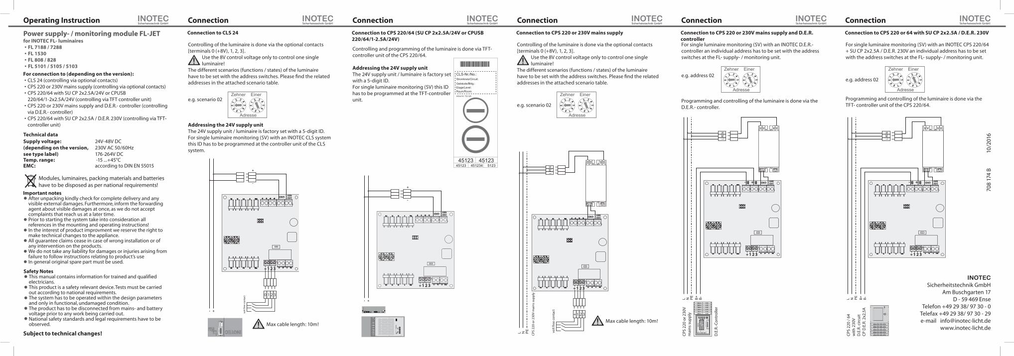
Operating Instruction
Power supply- / monitoring module FL-JETfor INOTEC FL- luminaires• FL 7188 / 7288 • FL 1530• FL 808 / 828• FL 5101 / 5105 / 5103
Technical dataSupply voltage:(depending on the version, see type label)
24V-48V DC230V AC 50/60Hz176-264V DC
Temp. range: -15 ...+45°CEMC: according to DIN EN 55015
Connection Connection Connection Connection Connection
Important notesAfter unpacking kindly check for complete delivery and any visible external damages. Furthermore, inform the forwarding agent about visible damages at once, as we do not accept complaints that reach us at a later time.Prior to starting the system take into consideration all references in the mounting and operating instructions!In the interest of product improvment we reserve the right to make technical changes to the appliance.All guarantee claims cease in case of wrong installation or of any intervention on the products. We do not take any liability for damages or injuries arising from failure to follow instructions relating to product’s useIn general original spare part must be used.
Modules, luminaires, packing materials and batterieshave to be disposed as per national requirements!
Safety NotesThis manual contains information for trained and qualified electricians.This product is a safety relevant device. Tests must be carried out according to national requirements.The system has to be operated within the design parameters and only in functional, undamaged condition.The product has to be disconnected from mains- and battery voltage prior to any work being carried out.National safety standards and legal requirements have to be observed.
Subject to technical changes!
+-
+
-
0 1 2 3
321+
GND 24V48V
INO
TE
C
12
34
56
78
91
01
11
21
31
41
51
61
71
81
92
0
SK
1S
K 2
SK
3S
K 4
Ein
/On
Stö
run
gF
ailu
re
Ein
/On
Stö
run
gF
ailu
re
Ein
/On
Stö
run
gF
ailu
re
Ein
/On
Stö
run
gF
ailu
re
La
de
Stö
run
gC
ha
rge
failu
re
Stö
run
gF
ailu
re
Bat
t.-B
etri
ebB
at.-O
pera
tion
Bet
rieb
Ope
ratio
n
OK
ES
C
volt
free
con
tact
+-
321+
GND 24V48V
1 2
CP
24V
2x2
,5A
F F = B
L / N
M=
DL
/ M5 AT 50
SK
1B
usS
K2
SK
3S
K4
CP
SU
VApo
t.fre
iK
onta
kte
24V
SL-
SL+
INO
TE
CC
PU
SB
24
V 2
x2,5
A
12
Adr
esse
AT
10
00
+
-
L N PE
+ 1 2 3
321+
GND 24V48V
N PE
L
volt
free
con
tact
CPS
220
or 2
30V
mai
ns s
uppl
y
L N B+
B-
PE
321+
GNDB +B -24V48V
TT
TT
TT
RR
RR
RR
Be
trie
bB
etr
ieb
Be
trie
bB
etr
ieb
Be
trie
bB
etr
ieb
Stö
run
gS
töru
ng
Stö
run
gS
töru
ng
Stö
run
gS
töru
ng
FW
99
FW
99
FW
99
FW
99
FW
99
FW
99
Test
Test
Test
Test
Test
Test
INOT
EC
Key-B
oard
Flu
ch
twe
g.
B
el.
Be
trie
b
Die
nsta
g
Mu
ste
r
27
.03
12
:00
Me
nu
eM
on
tag
M
uste
r
Flu
ch
twe
g.
Be
l.B
etr
ieb
27.
03.
11:3
0
Me
nu
e
Lade
Stör
ung
Netz-
Ausfa
ll
Stör
ung
Betri
eb
Druc
ker C
entro
nics
N PE
L
CPS
220
or 2
30V
mai
ns s
uppl
y
D.E
.R.-C
ontr
olle
r
L N B+
B-
PE
321+
GNDB +B -24V48V
N PE
L
4
CP
2x2,
5A
3,15
A
= D
L / M
F
3
3,15
A
F
2
3,15
A
F
2
3,15
A
F
4
CP
2x2,
5A
3,15
A
= D
L / M
F
3
3,15
A
F
2
3,15
A
F
2
3,15
A
F
4
CP
2x2,
5A
3,15
A
= D
L / M
F
3
3,15
A
F
2
3,15
A
F
2
3,15
A
F
4
CP
2x2,
5A
3,15
A
= D
L / M
F
3
3,15
A
F
2
3,15
A
F
2
3,15
A
F
4
CP
2x2,
5
3,15
A
= D
L / M
F
3
3,15
A
F
2
3,15
A
F
2
3,15
A
F
Me
nu
e
US
B
CPS
220
/ 64
with
230
V D
.E.R
. circ
uit
CP D
.E.R
. 2x2
,5A
Connection to CLS 24 Connection to CPS 220/64 (SU CP 2x2.5A/24V or CPUSB 220/64/1-2.5A/24V)
Connection to CPS 220 or 230V mains supply Connection to CPS 220 or 230V mains supply and D.E.R. controller
Connection to CPS 220 or 64 with SU CP 2x2.5A / D.E.R. 230V
CLS-Nr./No.:Stromkreis/Circuit:
Gebäude/Bldg.:Etage/Level:Raum/Room:Artikel-Nr. 702 026
451234 512345123 45123
45123
For connection to (depending on the version):• CLS 24 (controlling via optional contacts)• CPS 220 or 230V mains supply (controlling via optional contacts)• CPS 220/64 with SU CP 2x2.5A/24V or CPUSB
220/64/1-2x2.5A/24V (controlling via TFT controller unit)• CPS 220 or 230V mains supply and D.E.R.- controller (controlling
via D.E.R.- controller)• CPS 220/64 with SU CP 2x2.5A / D.E.R. 230V (controlling via TFT-
controller unit)
INOTEC Sicherheitstechnik GmbH
Am Buschgarten 17D - 59 469 Ense
Telefon +49 29 38/ 97 30 - 0Telefax +49 29 38/ 97 30 - 29e-mail [email protected]
www.inotec-licht.de
70
8 17
4 B
10/2
016
Max cable length: 10m!Max cable length: 10m!