Embed Size (px)
Citation preview

Institutionen för systemteknikDepartment of Electrical Engineering
Examensarbete
Rhapsody on small processor platforms
Examensarbete utfört i Elektroniksystemvid Tekniska högskolan i Linköping
av
Per-Oskar Andersson
LITH-ISY-EX--08/4006--SE
Linköping 2008
Department of Electrical Engineering Linköpings tekniska högskolaLinköpings universitet Linköpings universitetSE-581 83 Linköping, Sweden 581 83 Linköping

Rhapsody on small processor platforms
Examensarbete utfört i Elektroniksystemvid Tekniska högskolan i Linköping
av
Per-Oskar Andersson
LITH-ISY-EX--08/4006--SE
Handledare: Kent Palmkvistisy, Linköpings universitet
Anders SipuriCC Systems AB
Examinator: Kent Palmkvistisy, Linköpings universitet
Linköping, 2 June, 2008


Avdelning, InstitutionDivision, Department
Department of Electrical EngineeringDepartment of Electrical EngineeringLinköpings universitetSE-581 83 Linköping, Sweden
DatumDate
2008-06-02
SpråkLanguage
� Svenska/Swedish� Engelska/English
�
�
RapporttypReport category
� Licentiatavhandling� Examensarbete� C-uppsats� D-uppsats� Övrig rapport�
�
URL för elektronisk versionhttp://www.isy.liu.se
http://urn.kb.se/resolve?urn=urn:nbn:se:liu:diva-4006
ISBN—
ISRNLITH-ISY-EX--08/4006--SE
Serietitel och serienummerTitle of series, numbering
ISSN—
TitelTitle
Rhapsody på små processorplattformarRhapsody on small processor platforms
FörfattareAuthor
Per-Oskar Andersson
SammanfattningAbstract
Rhapsody is a Model-Driven Development (MDD) tool for embedded and real-timesystem design. The purpose of this thesis is to determine if Rhapsody can be usedfor software development on small processor platforms such as the Atmel AVR.Rhapsody is normally used on platforms running an operating system. Thereforecertain adaptations are needed in order to use it on platforms without an operatingsystem. These adaptations and their affect on the usability of the tool, advantagesand disadvantages are all studied while porting AVR-software to Rhapsody on oneof CC Systems products, the robust on-board computer CC Pilot XL II.
NyckelordKeywords UML, Rhapsody, Code-Generation, AVR


AbstractRhapsody is a Model-Driven Development (MDD) tool for embedded and real-timesystem design. The purpose of this thesis is to determine if Rhapsody can be usedfor software development on small processor platforms such as the Atmel AVR.Rhapsody is normally used on platforms running an operating system. Thereforecertain adaptations are needed in order to use it on platforms without an operatingsystem. These adaptations and their affect on the usability of the tool, advantagesand disadvantages are all studied while porting AVR-software to Rhapsody on oneof CC Systems products, the robust on-board computer CC Pilot XL II.
SammanfattningRhapsody är ett verktyg för modelldriven utveckling och design av inbyggda sy-stem och realtidssystem. Syftet med detta examensarbete är att undersöka omRhapsody kan användas för att utveckla mjukvara till små processorplattformarsom Atmel’s AVR. Då Rhapsody normalt används till plattformar med ett ope-rativsystem behöver vissa modifieringar göras för att möjliggöra utveckling motplattformar utan operativsystem. Dessa modifieringar, deras för och nackdelarsamt påverkan på utvecklingsprocessen undersöks medan AVR-mjukvara porterastill Rhapsody. Mjukvaran som porteras är en del av styrsystemet till en av CCSystems produkter: CC Pilot XL II, en robust fordonsdator.
v


Acknowledgments
I would like to thank Anders Sipuri, Johan Strandberg and Anders Öberg at CCSystems for excellent support and supervision during the making of this thesis. Ialso want to thank the rest of the staff in Alfta for making it a great time! Bigthanks also to my university supervisor Kent Palmkvist.
vii


Contents
1 Introduction 11.1 Background . . . . . . . . . . . . . . . . . . . . . . . . . . . . . . . 11.2 Goals . . . . . . . . . . . . . . . . . . . . . . . . . . . . . . . . . . 11.3 Limitations . . . . . . . . . . . . . . . . . . . . . . . . . . . . . . . 21.4 Hardware and Software . . . . . . . . . . . . . . . . . . . . . . . . 2
1.4.1 Hardware . . . . . . . . . . . . . . . . . . . . . . . . . . . . 21.4.2 Software . . . . . . . . . . . . . . . . . . . . . . . . . . . . . 3
1.5 Organisation . . . . . . . . . . . . . . . . . . . . . . . . . . . . . . 3
2 UML Introduction 52.1 UML 2.0 . . . . . . . . . . . . . . . . . . . . . . . . . . . . . . . . . 52.2 UML Views . . . . . . . . . . . . . . . . . . . . . . . . . . . . . . . 6
2.2.1 Use-Case View . . . . . . . . . . . . . . . . . . . . . . . . . 62.2.2 Logical View . . . . . . . . . . . . . . . . . . . . . . . . . . 62.2.3 Implementation View . . . . . . . . . . . . . . . . . . . . . 72.2.4 Process View . . . . . . . . . . . . . . . . . . . . . . . . . . 72.2.5 Deployment View . . . . . . . . . . . . . . . . . . . . . . . . 7
2.3 UML Model Elements . . . . . . . . . . . . . . . . . . . . . . . . . 72.4 UML Relationships . . . . . . . . . . . . . . . . . . . . . . . . . . . 82.5 UML Diagrams . . . . . . . . . . . . . . . . . . . . . . . . . . . . . 9
2.5.1 Class Diagram . . . . . . . . . . . . . . . . . . . . . . . . . 102.5.2 Object Diagram . . . . . . . . . . . . . . . . . . . . . . . . 102.5.3 Component Diagram . . . . . . . . . . . . . . . . . . . . . . 112.5.4 Composite Structure Diagram . . . . . . . . . . . . . . . . . 112.5.5 Package Diagram . . . . . . . . . . . . . . . . . . . . . . . . 112.5.6 Deployment Diagram . . . . . . . . . . . . . . . . . . . . . 122.5.7 Use Case Diagram . . . . . . . . . . . . . . . . . . . . . . . 132.5.8 Activity Diagram . . . . . . . . . . . . . . . . . . . . . . . . 132.5.9 State Diagram . . . . . . . . . . . . . . . . . . . . . . . . . 142.5.10 Sequence Diagram . . . . . . . . . . . . . . . . . . . . . . . 152.5.11 Communication Diagram . . . . . . . . . . . . . . . . . . . 152.5.12 Timing Diagram . . . . . . . . . . . . . . . . . . . . . . . . 162.5.13 Interaction Overview Diagram . . . . . . . . . . . . . . . . 16
ix

x Contents
3 Rhapsody 173.1 Rhapsody Introduction . . . . . . . . . . . . . . . . . . . . . . . . . 173.2 User Interface . . . . . . . . . . . . . . . . . . . . . . . . . . . . . . 173.3 UML in Rhapsody . . . . . . . . . . . . . . . . . . . . . . . . . . . 18
3.3.1 Statecharts . . . . . . . . . . . . . . . . . . . . . . . . . . . 193.3.2 Object Model Diagrams . . . . . . . . . . . . . . . . . . . . 20
3.4 Rhapsody Without an OS . . . . . . . . . . . . . . . . . . . . . . . 213.4.1 Interrupt Driven Framework . . . . . . . . . . . . . . . . . 213.4.2 No Framework . . . . . . . . . . . . . . . . . . . . . . . . . 22
4 Method 234.1 Choosing a Compiler . . . . . . . . . . . . . . . . . . . . . . . . . . 234.2 Implementation Language . . . . . . . . . . . . . . . . . . . . . . . 234.3 Property-Files . . . . . . . . . . . . . . . . . . . . . . . . . . . . . . 244.4 Hardware . . . . . . . . . . . . . . . . . . . . . . . . . . . . . . . . 244.5 Debugging . . . . . . . . . . . . . . . . . . . . . . . . . . . . . . . . 254.6 Software . . . . . . . . . . . . . . . . . . . . . . . . . . . . . . . . . 25
4.6.1 PC-Module . . . . . . . . . . . . . . . . . . . . . . . . . . . 264.6.2 Display-Module . . . . . . . . . . . . . . . . . . . . . . . . . 264.6.3 Example Project . . . . . . . . . . . . . . . . . . . . . . . . 27
4.7 Implementation Methods . . . . . . . . . . . . . . . . . . . . . . . 294.7.1 IDF . . . . . . . . . . . . . . . . . . . . . . . . . . . . . . . 294.7.2 NOF . . . . . . . . . . . . . . . . . . . . . . . . . . . . . . . 294.7.3 Manual Statechart Implementation . . . . . . . . . . . . . . 30
5 Results 315.1 Example Project . . . . . . . . . . . . . . . . . . . . . . . . . . . . 325.2 PC Module . . . . . . . . . . . . . . . . . . . . . . . . . . . . . . . 335.3 Display Module . . . . . . . . . . . . . . . . . . . . . . . . . . . . . 345.4 Summary . . . . . . . . . . . . . . . . . . . . . . . . . . . . . . . . 35
6 Discussion 376.1 Rhapsody Experiences . . . . . . . . . . . . . . . . . . . . . . . . . 376.2 State Machine Modelling . . . . . . . . . . . . . . . . . . . . . . . . 376.3 Alternative Uses of Rhapsody . . . . . . . . . . . . . . . . . . . . . 386.4 What Method to Use? . . . . . . . . . . . . . . . . . . . . . . . . . 386.5 Other Tools . . . . . . . . . . . . . . . . . . . . . . . . . . . . . . . 396.6 Future Work . . . . . . . . . . . . . . . . . . . . . . . . . . . . . . 396.7 Conclusions . . . . . . . . . . . . . . . . . . . . . . . . . . . . . . . 40
7 Glossary 41
Bibliography 43
A HeatingController 45

Chapter 1
Introduction
This thesis has been written within the context of master thesis studies at theComputer Science and Engineering programme (D-programme) at Linköping Uni-versity. The topic of the thesis has been suggested by CC Systems AB and mostof the work has been performed at their office in Alfta.
CC Systems is a electronics/software company which supplies control systems,products and platforms for various types of heavy vehicles. One of these productsis the CC Pilot XL II which is a powerful and robust on-board PC.
This thesis investigates if it is possible to use the code-generating tool Rhapsodyto develop software for small processor platforms such as the Atmel AVR which isused in CC Pilot XL II.
1.1 BackgroundRhapsody is a Unified Modeling Language (UML) based tool which can generatesource code targeting embedded systems. With such a tool it is possible to reducedevelopment time and automatically improve documentation and overview com-pared to manual development. Rhapsody can be used in all the steps in creatingan application: Analysis, Design, Implementation and testing.
The CCP XL II is composed by a display unit and a PC unit. Each of theseunits has an AVR processor which handles internal communication, backlight con-trol and temperature monitoring among other things. The two AVR processorshave state machine based software. CC Systems wants to update this softwareusing Rhapsody in order to simplify maintenance and further development.
1.2 GoalsThe main goals of this thesis project was to study if and how Rhapsody can be usedto generate code for Atmel AVR by making working Rhapsody-implementations ofthe existing AVR-software. Since Rhapsody is primarily used on platforms runningan operating system, the necessary steps to make it usable on small processor
1

2 Introduction
platforms needed to be investigated. If there was enough time, or if Rhapsody wasdeemed not suitable for small processor platforms, other similar tools were to beinvestigated as well.
1.3 LimitationsIn order to fulfill the goal of making working Rhapsody implementations, severallimitations have been imposed on the project. Although there are several similarproducts on the market, Rhapsody is the only tool investigated in this thesis. Dueto licensing issues, the version of Rhapsody used in this thesis is 6.1 althoughnewer versions were available. The techniques discussed in this thesis could beused on a number of different small platform systems, but they have only beentested on two members of the Atmel AVR family of microcontrollers. Due to thesheer size of the generated code and in consideration of the company’s copyright,no production code is included in the thesis. Instead, a small example project hasbeen developed for demonstrating purposes.
1.4 Hardware and Software
1.4.1 HardwareThe following hardware has been used in the context of this thesis:
• CC Systems CC Pilot XL IIThe CC Pilot XL II is a powerful, versatile and robust on-board PC, ideal foruse in control and information systems. It is composed by a display moduleand a PC module and uses Windows XP as operating system. For detailedinformation see the product leaflet [1].
Figure 1.1. CC Pilot XL II

1.5 Organisation 3
• Atmel AVR R© JTAGICE mkIIThe JTAGICE mkII is a development tool for On-chip debugging of AtmelAVR processors. For detailed information see the Atmel website [2].
• Atmel ATMega16 and ATMega644The Atmel ATMega16 and ATMega644 microcontrollers are part of Atmel’slow-power CMOS 8-bit microcontroller series based on the AVR enhancedRISC architecture. The two microcontrollers are pin-compatible and themain difference between them is that Mega644 has larger Flash programmemory, EEPROM and SRAM. Detailed information and data sheets areavailable at [3] and [4].
1.4.2 SoftwareThe following software tools have been used in the context of this thesis:
• Ilogix Rhapsody 6.1Ilogix Rhapsody is a Model-Driven Development (MDD) tool. Rhapsody isthoroughly described in chapter 3 Rhapsody. See the telelogic website [5]for the latest version.
• IAR Systems IAR Embedded workbench 4.21IAR Embedded Workbench is a set of development tools for building anddebugging embedded applications using assembler, C and C++. See theIAR website [6] for more information.
• Atmel AVR Studio 4Atmel AVR Studio 4 is an Integrated Development Environment (IDE) forwriting and debugging AVR applications. See the Atmel website [7] for moreinformation.
1.5 OrganisationThe thesis is organised in the following chapters:
• Chapter 1 IntroductionIntroduction, background and goals for the thesis.
• Chapter 2 UML IntroductionShort theoretical introduction to UML. Readers allready familiar with UMLmay want to skip this chapter.
• Chapter 3 RhapsodyShort introduction to Rhapsody explaining the necessary concepts discussedin the later chapters.
• Chapter 4 MethodDescribes the methods that was used to port AVR software to Rhapsody.

4 Introduction
• Chapter 5 ResultsPresents the results of the different methods.
• Chapter 6 DiscussionDiscussion of the results and future work.

Chapter 2
UML Introduction
The Unified Modeling Language (UML) is an industry-standard language used tomodel systems. Primarily it is used to model object-oriented software systems,but it can also be used for other purposes such as business modelling. Graphicalobjects are used in different types of diagrams for specification, visualisation anddocumentation. UML is managed by The Object Management Group [8] togetherwith the software industry. At the time of writing this thesis, the latest publishedversion was UML 2.1.1 (2007).
This chapter is by no means a full description of UML, there are many bookswritten on this subject, but rather a short introduction describing the most im-portant language elements, some of which are referenced later in this thesis. Forreaders that want to study UML 2.0 further, [9] and [10] are recommended.
2.1 UML 2.0Version 2.0 of UML introduced a number of new constructs, elements and diagramsas well as improved language organisation, domain specific specializations and ahigher degree of precision in the language definition. This makes Model DrivenDevelopment possible to a greater extent than in UML 1.x.
Some examples of improvements are:
• Nested ClassifiersClassifiers (Model elements such as Classes, Objects, Activities) can benested which, for example, makes complex state machines possible by nestingmany simple statemachines.
• Four New DiagramsUML 2.0 introduces the Package Diagram, Composite Structure Diagram,Timing Diagram and the Interaction Overview Diagram.
• Improved Symbols and SemanticsThe symbols have been improved or changed in many of the diagrams, addingmore functionality and better semantics for the different diagrams.
5

6 UML Introduction
• Better ExtendabilityUML 2.0 offers better extendability than UML 1.x. Stereotypes, profiles andOCL can be used to adapt the language to specific domains.
2.2 UML ViewsIdeally, describing an entire system in one easy to understand graph would bepreferred. This is however impossible in all but the most simple cases. Theconcept of views has therefore been introduced to UML. Each view is describedby a number of UML diagrams, described in section 2.5 – together describing aparticular aspect of the design. The UML 4+1 View model is shown in Figure 2.1and will be described in this section.
Figure 2.1. UML 4+1 View Model
2.2.1 Use-Case ViewThe use-case view describes the functionality the system should deliver. It isintended for customers, designers, developers and testers. The desired usage ofthe system is described in a set of use-case diagrams. Activity diagrams may alsobe used in this view. The use-case view ties all the other views together.
2.2.2 Logical ViewThis view describes how the system functionality is provided, in terms of struc-tural elements. Different levels of abstraction describe the logical architecture.A number of diagrams are used in this view: Class diagrams, Object diagrams,Package diagrams, Composite Structure diagrams and State diagrams. Modelingbegins with Class and Package diagrams and is then expanded as needed with theother diagrams.

2.3 UML Model Elements 7
2.2.3 Implementation ViewThe implementation view, sometimes called component view, focuses on softwaremodule organization. Software is packaged into components which can be devel-oped and tested. The component diagram is the only diagram used in this view.
2.2.4 Process ViewThe process view divides the system into processes and processors, addressingissues of concurrency, distribution and fault tolerance. Sequence and Communi-cation diagrams are the most commonly used diagrams. The view can also beextended with activity, timing and interaction overview diagrams.
2.2.5 Deployment ViewThe deployment view shows the physical deployment of the system, in terms ofprocessing elements such as computers and which processes that run on them. Theconnection between the elements to form the complete system is also describedhere. In order to describe this, deployment diagrams are used.
2.3 UML Model ElementsThere are a great number of building elements in UML 2.0, structural, behavioral,grouping and annotational elements. It is difficult to classify them, since many ofthem can be part of both structural and behavioral diagrams. The elements areconnected by relationships to create complete diagrams. This section describesexamples of some of the most important or most used elements which can be seenin Figure 2.2.
Figure 2.2. UML Elements

8 UML Introduction
• ClassA class is a description of an object type. The class describes the propertiesand behaviour of all instansiated objects of the class. A class is a structuralelement.
• ObjectObjects are run time instantiations of classes. Objects can be both structuraland behavioral.
• ComponentA component is an replaceable, executable entity used in component dia-grams. Components are structural elements.
• PackageA package is a representation of a directory. A way to organize elementshierarchically. Packages are grouping elements.
• Use CaseA use case describes a functionality that the system will have or a goal thatan actor wants to fulfill. This is done witout describing how it is implementedin any way. A use case is behavioral.
• ActivityActivities are behavioral elements used in activity diagrams to represent aphysical or logical activity.
• StateStates are behavioral elements used in state diagrams to represent the dif-ferent states the model can have.
• NoteA note is an annotational element, usually used as a short description of adiagram.
2.4 UML RelationshipsAn UML relationship is a connection between model elements adding semantics tothe model. There are about 20 relationships defined. Figure 2.3 shows examplesof some of the most used relationships.
• DependencyA dependency relationship indicates that a change of the supplier modelelement may affect the client model element (but not the reverse).
• AssociationAn association relationship is a structural relationship between two elementsthat shows that objects of one classifier connect to objects of the other clas-sifier.

2.5 UML Diagrams 9
• Directional AssociationA directed association is a one way navigable association.
• GeneralizationA generalization specifies that a child element is based on a general parentelement. Typically one parent has multiple children.
• AggregationAn aggregation specifies that one element is a part of another element.
Figure 2.3. UML Relationship Examples
2.5 UML DiagramsUML diagrams are the actual graphs that show how the different model elementsare arranged and related. Each diagram is drawn to illustrate a particular aspectof the system and a system is usually described by several types of diagrams.Diagrams are often part of specific views as described in 2.2 and a diagram is oftenallocated to a view when it is drawn. This section describes the basic conceptsbehind each of the thirteen types of diagrams defined in UML 2.1.1. The diagramsare divided into three categories:
• Structure DiagramsIncludes the Class Diagram, Object Diagram, Component Diagram, Com-posite Structure Diagram, Package Diagram and the Deployment Diagram.
• Behavior DiagramsIncludes the Use Case Diagram, Activity Diagram and the State Diagram.
• Interaction DiagramsIncludes the Sequence Diagram, Communication Diagram, Timing Diagramand the Interaction Overview Diagram.

10 UML Introduction
2.5.1 Class Diagram
Class diagrams show the static structure of classes in the system. Static, in thiscase, means that the described structure is valid at all time in the life cycle of theapplication. The class attributes and operations and the relationships between theclasses are shown.
Figure 2.4. Class Diagram Example
2.5.2 Object Diagram
An Object diagram is a variant of a class diagram and uses a similar notation.Instead of classes, the object diagram shows a snapshot image of the object in-stances at a specific time. It can be used to exemplify a complex class diagram.
Figure 2.5. Object Diagram Example

2.5 UML Diagrams 11
2.5.3 Component Diagram
Component diagrams show the physical structure of the code in terms of compo-nents. A component can be a source code component, a binary or an executablecomponent. Dependencies between the different components are shown, as well astheir respective interfaces. The component diagram is particularly good for earlyarchitectural modelling of a system.
Figure 2.6. Component Diagram Example
2.5.4 Composite Structure Diagram
Composite structure diagrams describe the functionality or the internal structureof a classifier. It can represent the different parts of a class. It can also representthe collaboration of a set of interconnected elements at runtime. The elements orthe classifiers themselves can interact through ports or connectors. The diagramtype is good to use early in the design phase.
Figure 2.7. Composite Structure Diagram Example
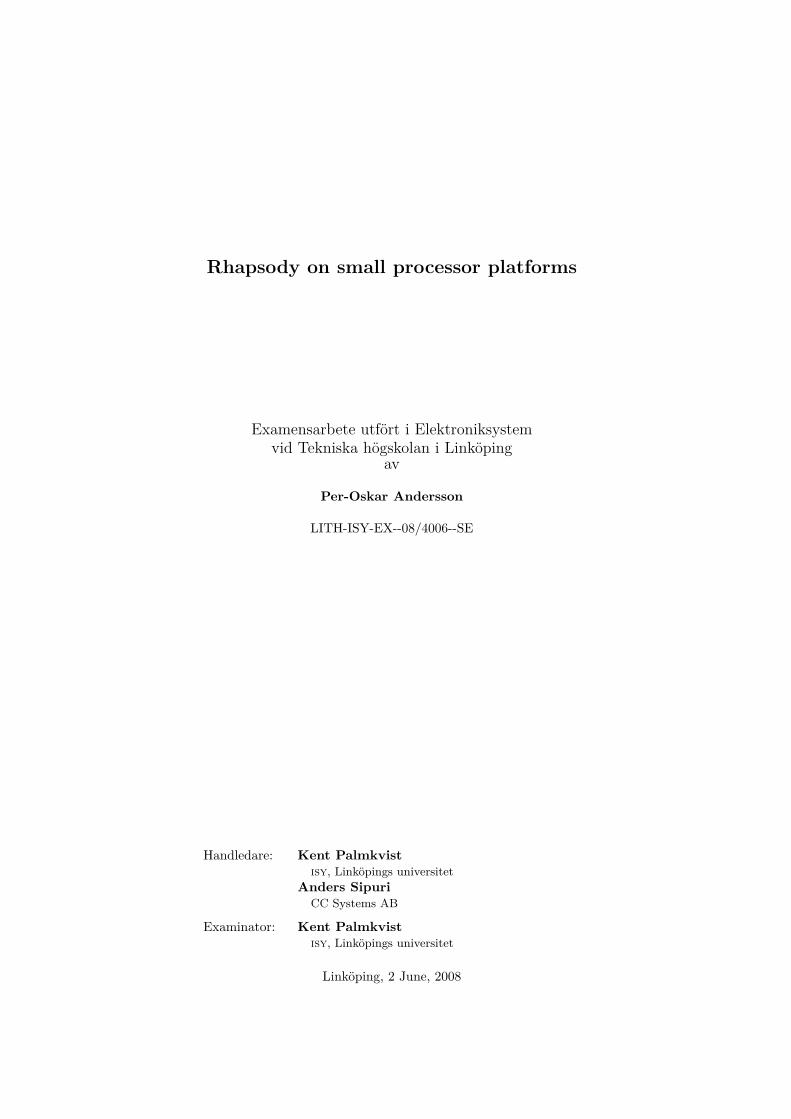
2.5.5 Package Diagram
Package diagrams describe the system in terms of logical groupings. Only pack-ages and the relations between them are allowed in a package diagram. Packagestypically represent a directory, allowing for a logical hierarchical representation ofthe elements of the system. Package diagrams show a high level overview of thearchitecture.
12 UML Introduction
Figure 2.8. Package Diagram Example
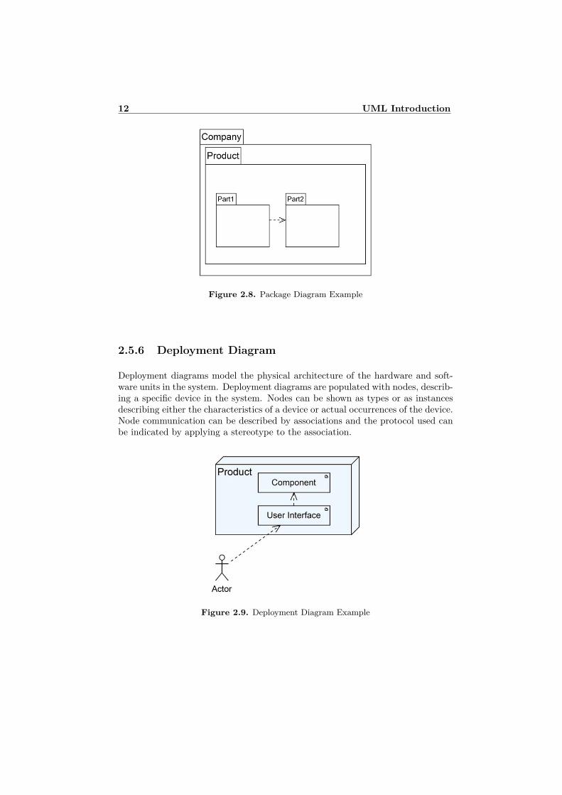
2.5.6 Deployment Diagram
Deployment diagrams model the physical architecture of the hardware and soft-ware units in the system. Deployment diagrams are populated with nodes, describ-ing a specific device in the system. Nodes can be shown as types or as instancesdescribing either the characteristics of a device or actual occurrences of the device.Node communication can be described by associations and the protocol used canbe indicated by applying a stereotype to the association.
Figure 2.9. Deployment Diagram Example
2.5 UML Diagrams 13
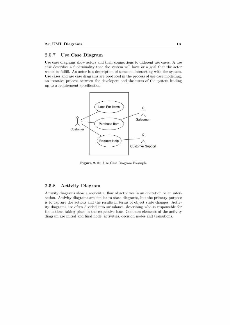
2.5.7 Use Case DiagramUse case diagrams show actors and their connections to different use cases. A usecase describes a functionality that the system will have or a goal that the actorwants to fulfill. An actor is a description of someone interacting with the system.Use cases and use case diagrams are produced in the process of use case modelling,an iterative process between the developers and the users of the system leadingup to a requirement specification.
Figure 2.10. Use Case Diagram Example
2.5.8 Activity DiagramActivity diagrams show a sequential flow of activities in an operation or an inter-action. Activity diagrams are similar to state diagrams, but the primary purposeis to capture the actions and the results in terms of object state changes. Activ-ity diagrams are often divided into swimlanes, describing who is responsible forthe actions taking place in the respective lane. Common elements of the activitydiagram are initial and final node, activities, decision nodes and transitions.

14 UML Introduction
Figure 2.11. Activity Diagram Example
2.5.9 State DiagramState diagrams capture the life cycle of objects or systems. They describe thedifferent states the object can be in and how events affect the states over time. Asystem can only be in one of the possible states unless a special type of state isused, concurrent states (AND or OR-states). The transition between states can beinitiated by an event and guarded by a guard-condition. Actions can be performedon state changes. States can also have state variables, representing the attributesof a class. Common elements used in state diagrams are initial and final node,states, transitions, events, actions and guards. State diagrams are also explainedin section 3.3.1, Statecharts.
Figure 2.12. State Diagram Example

2.5 UML Diagrams 15
2.5.10 Sequence DiagramSequence diagrams model the exchange of messages over time between objects.Time passes downward the vertical lines in the diagram and timing constraints canbe added if applicable. Sequence diagrams model specific run time scenarios of themessages exchanged and the correct order of them. Messages can be synchronousor asynchronous represented by horizontal arrows with solid or stick heads. Thelifetime of objects can also be specified by marking the destruction of the objectby an X on the life line.
Figure 2.13. Sequence Diagram Example
2.5.11 Communication DiagramCommunication diagrams model the interactions between objects and the mes-sages that are passed. In order to show the sequence of messages, a chronologicalnumber is added to each message indicating the correct order. Communicationdiagrams, formerly known as collaboration diagrams in UML 1, uses a combina-tion of information from the Class, Sequence and Use case diagrams to show acollection of collaborating objects.
Figure 2.14. Communication Diagram Example

16 UML Introduction
2.5.12 Timing DiagramTiming diagrams are a special type of sequence diagram, focusing on timing con-straints. They show the behaviour of objects in a given period of time. Timeis increased from left to right and the diagram is similar to electrical hardwaretiming diagrams used by electrical engineers. The timeline can be discrete or ageneral value lifeline, described by text.
Figure 2.15. Timing Diagram Example
2.5.13 Interaction Overview DiagramInteraction overview diagrams are a variation of activity diagrams. They visualizethe interaction between different interaction diagrams such as sequence diagrams,communication diagrams or even another interaction overview diagram. The dia-gram notation is exactly the same as in activity diagrams, but the activity elementsare replaced by an interaction diagram which is drawn in a frame.
Figure 2.16. Interaction Overview Diagram Example

Chapter 3
Rhapsody
3.1 Rhapsody IntroductionI-Logix Rhapsody was developed by I-Logix, a company acquired by Telelogic ABin 2006. The version 6.1 described here was developed before the acquisition.Future versions are therefore called Telelogic Rhapsody.
Rhapsody is a Model-Driven Development (MDD) tool for embedded and real-time system design. Rhapsody generates code from graphical models which can bespecified in the modelling languages UML 2.0, SysML or DoDAF. The entire de-sign process can be modelled in Rhapsody, from analysis and system design withrequirements and use-cases, to development, simulation and verification. Lan-guages supported for code-generation is C, C++, Ada, and Java. The generatedcode can be edited by the user and the changes can dynamically be roundtrippedback into the graphical model.
The code generated by Rhapsody is Operating System (OS) independent.Support for individual Real Time Operating Systems (RTOS) is made througha framework called object execution framework (OXF). The OXF itself is alsoOS-independent, except for a set of adaptor classes called OS abstraction layer(OSAL). In order to support a new RTOS, the OXF needs to be rebuilt for thenew target, but only the OSAL needs to be set up for the new environment. Rhap-sody comes with support for some commonly used real time operating systems,including Linux, OSE and VxWorks. Since the generated code is OS-independent,the same model can be used to generate code for different target systems at thesame time.
3.2 User InterfaceThe Rhapsody user interface is comprised of a set of toolbars, the RhapsodyBrowser and the Diagram Drawing Area. Typically the user selects a statechartor another type of diagram in the browser and then edits it in the diagram drawingarea. When items are drawn on a diagram, Rhapsody automatically updates the
17

18 Rhapsody
model with the new elements.All parts of the project can be seen in the Rhapsody browser. The browser is
used to change initial values of variables, edit the code for operations or to add newclasses, statecharts or other items. It is also used for accessing the huge amount ofproperties associated with each type of element. Different kinds of popup windowsare used for these operations. Figure 3.1 shows the user interface when workingwith the example project described in 4.6.3.
Figure 3.1. Rhapsody User Interface
3.3 UML in RhapsodyRhapsody has full support for UML 2.0 as well as several other standards. How-ever, most of the diagram-types are not directly used for code-generation, butinstead for documentation and analysing purposes. The constructive diagramsin Rhapsody are Object Model Diagrams (OMDs), Statecharts and Activity di-agrams. The constructive diagrams will be discussed further below. SequenceDiagrams are partially constructive; Rhapsody can create objects and operationsfrom them, but the behaviour of the objects and operations will have to be definedin an OMD, Statechart or in code. Non-constructive diagrams such as Use CaseDiagrams and Requirements Diagrams can be drawn as part of the design process.
This section covers the diagrams used in this thesis, which are related to code-generation in Rhapsody: Statecharts and OMDs.

3.3 UML in Rhapsody 19
3.3.1 StatechartsStatecharts and Activity Diagrams are both used to describe the behaviour ofa class, but they can also be used for other types of objects. Statecharts aremore suited for event-driven behaviour while activity diagrams are best used forworkflow behaviour that is not event-driven. This is because statecharts usuallyremain in one state until an internal or external event occurs. A class can have astatechart or an activity diagram but not both. Statecharts and activity diagramsare not very different; the code generated from them is almost identical. Activitydiagrams will not be used in this thesis project, which is why only statecharts isdescribed more thorough.
A statechart is Rhapsody’s representation of the UML state diagram. State-charts is a powerful tool to model a system’s behaviour over time. It is a represen-tation of a finite state machine. Statecharts consist of states, transitions, triggers,guards and actions.
• StateA state is a graphical representation of the status of an object. States can benested; there is no limit on the number of substates or levels of states. Twospecial types of states are worth mentioning; Or-states and And-states. AnOr-state is a state broken down into exclusive substates, the state is alwaysexclusively in either of the substates. And-states represent a concurrent statewhere each substate is active concurrently.
• TransitionA transition is the representation of a change of state. Transitions can havea trigger, guard, and actions.
• TriggerThere are three types of triggers which can be used in Rhapsody: events,triggered operations and timeouts. An event is an asynchronous, one-waycommunication between objects. A triggered operation is synchronous andcan have a return-value. A timeout is a special operation with the syntaxtm(timeunit) where timeunit usually is milliseconds. The timeout is sched-uled when the origin state is entered. It triggers after the specified time aslong as the origin state has not been left.
• GuardGuards are expressions that must evaluate to true for the transition to takeplace. A guard can be a variable or a function.
• ActionActions are functions or code that is executed when the transition takesplace.

20 Rhapsody
Figure 3.2 shows a small example of a Statechart drawn in Rhapsody containingtwo states, three transitions, an event, a timeout and a guard. A default transitionmakes the system start by entering the Idle state. When an event called evActiveoccurs, the action doStuff() is executed, and the system enters the Active state.A timeout is triggered after 1000 ms but the transition back to the Idle state isonly taken if the guard isDone? is true.
Figure 3.2. Rhapsody Statechart Example
3.3.2 Object Model DiagramsAn Object Model Diagram (OMD) is a combination of the UML class diagramand the UML object diagram. It specifies the structure and static relations ofthe classes in a system. Classes, objects and packages as well as many differentrelations can be drawn in the diagram; Rhapsody generates code for everythingdrawn.
A Class is a description of a set of objects that have the same properties.Classes can contain attributes, operations, events, relations and many other things.Objects are basically instantiations of a class but objects can also be createdwithout specifying a class. Packages are containers for classes and objects. Allclasses must be placed in a package, if a class is not placed in a specific package,it will be put in the default package. Examples of relations are dependency,association and inheritance.
Figure 3.3 shows a small example of an OMD. A home heating system withone furnace and three rooms are modelled. Two classes, Furnace and Room aremodelled in a package called HomeHeatingSystem. These two classes have a fewattributes and operations. An association between the two classes models thestatic relation between them. Each Furnace-object has three rooms and eachRoom object is associated with one furnace.

3.4 Rhapsody Without an OS 21
Figure 3.3. Rhapsody OMD Example
3.4 Rhapsody Without an OSRhapsody is primarily targeted for 32-bit processors running (real time) operatingsystems. It is however possible to use Rhapsody to develop code for environmentswithout an OS. In order to do that, the OXF needs to be replaced by a frameworkwhich does not depend on an operating system. The Interrupt Driven Framework(IDF) is such a framework and it is available for Rhapsody in C and C++. Insteadof using the operating systems support for threads and timers, this framework isdriven entirely by interrupts. There is also a way to use Rhapsody without aframework at all. This is simply a set of rules and settings incorporated into aRhapsody profile called No Framework (NOF).
3.4.1 Interrupt Driven FrameworkThe IDF itself is a Rhapsody model which can be customised by the developerto support new target environments. It is built into a library which should beincluded in projects using the IDF. The IDF replaces the OS and the OXF andworks in a way as a tiny operating system. This is illustrated in Table 3.1.
There are of course both advantages and disadvantages of using the IDF. Thebiggest advantage is that the IDF can be used on small targets for which there isno RTOS available. The IDF can also be used for testing on new environmentsbefore porting of the OXF has been done to the new OS. The downside is thatsome of the functionality of the OXF is not available for the IDF:

22 Rhapsody
• Threads can be used but they are not true threads. The threads are sched-uled by interrupts.
• Animation (graphical debugging) is not supported.
• Several code generation settings need to be set in a specific way.
• Some classes are not integrated with the IDF.
• No dynamic allocation of heaps. Specific sizes need to be set up for theenvironment.
To sum up, the developer has a more limited set of options when developingfor the IDF compared to the OXF.
Table 3.1. Rhapsody Framework Configuration
3.4.2 No FrameworkThe No Framework (NOF) approach is a way to use Rhapsody generated statechart-code without any framework. It imposes limitations in how Rhapsody can be used.Using the NOF-profile enables the use of statecharts, but there is no support for thetimeout-function tm(), which is often used with statecharts. Events can only becalled synchronously and without parameters, while the IDF supports synchronousand asynchronous events, with or without parameters.
The NOF is available as a Rhapsody profile (a file with settings that can beimported to projects) and two source code files containing macros and definitionsof some classes and functions necessary for statecharts. There is really only oneadvantage to using the NOF: The code size overhead associated with a frameworkis reduced which enables use on really small targets.

Chapter 4
Method
This study tries to determine if Rhapsody can be used to generate code for smallmicrocontrollers such as the Atmel ATMega16. In order to demonstrate this, twoexisting applications are ported to Rhapsody, and one small example project isdeveloped. This chapter describes the methods used and some of the problemsthat arose during the development.
4.1 Choosing a CompilerCC Systems currently uses the tool IAR Embedded Workbench (IAR) for someof their AVR projects. This tool includes both C and C++ compilers as well as alinker and all the necessary parts of a complete integrated development environ-ment. It also contains support for on-chip debugging through various interfaces.The drivers and the existing code for the CCP XL II were made with IAR. There-fore, it came naturally to try to use this tool with Rhapsody.
In order to compile, make and run from within the Rhapsody IDE, Rhapsodymust first be integrated with the IAR tools. Section 4.3 describes how this wasdone. Rhapsody could theoretically be used without performing this integration,but development would then require having the IAR IDE open at the same time,importing the code from Rhapsody. Rhapsody would be used only to generate thecode. This would however slow down the development time significantly. It is amajor advantage to be able to quickly compile in Rhapsody to see any generatederrors. As we will learn later on, it was still necessary to use the IAR IDE whendebugging on the actual hardware since no support for this exists in Rhapsody.
4.2 Implementation LanguageSince Rhapsody is available for several languages, including C and C++, it wasfirst necessary to make a choice between these two languages. The original softwarefor the CCP XL II was written in C, but since it is easy to use code written in Cin C++ projects, that did not affect the decision. The decision to use C++ was
23

24 Method
made after testing the C and C++ versions of the IDF. The C++ version waseasier and faster to get working with the AVR processors. Another big advantageof C++ was the ability to use the NOF-settings, which was only available forRhapsody in C++.
4.3 Property-FilesIn order to use IAR with Rhapsody, a settings-file must first be created. Such afile is called a property-file and it contains, in plain text, different properties andtheir values. The property-files are read by Rhapsody when a project is opened.
These files were created by studying the commands used by the IAR IDE duringcompilation and linking, while making changes to existing property-files used forother environments. In order to be able to change the settings of the IAR tools,such as what processor-type to compile for or whether to use IDF or NOF, it wasnecessary to create several files, one for each major setting. A sample from one ofthese files is included in Listing 4.1. The whole files are unfortunately too big to beincluded in this report. The files contain settings for the Rhapsody code-generator,IDF/NOF-related settings, paths to the IAR tools and a makefile-template thatRhapsody uses when building a program.
After setting up these files, Rhapsody uses the IAR compiler and linker toolsindependently, without any need for the IAR IDE. The IAR software must still beinstalled and licensed for the setup to work.
Listing 4.1. Property-file sample
Property BuildCommandSet Enum "Debug , Re lease " "Debug "Property SpecExtension St r ing " . h "Property ImpExtension St r ing " . cpp "Property CPPCompileRelease S t r ing " −z9
−−c ro s s_ca l l_pas s e s=2 −D NDEBUG"Property LinkDebug St r ing "− r t "Property LinkRelease S t r ing "−Finte l−extended "Property CPUModel S t r ing "m16"
4.4 HardwareThe CCP XL II is as described in section 1.4.1 based on two parts, the PC Moduleand the Display Module. The AVR processors in the modules are programmableby the JTAG-interface which is an industry-standard interface for integrated cir-cuits. IAR together with the Atmel JTAGICE mkII was used for code-loadingand debugging. During the project it was discovered that the original ATMega16microcontroller did not have enough memory to handle the code generated byRhapsody for the IDF. Therefore it was necessary to find a replacement microcon-troller in order to continue the project. Luckily, such a microcontroller existed,

4.5 Debugging 25
the ATMega644 which has the same footprint as the ATMega16. The two micro-controllers differ mainly by the size of the different memories according to Table4.1.
Flash program memory EEPROM SRAMATMega16 16K Bytes 512 Bytes 1K BytesATMega644 64K Bytes 2K Bytes 4K Bytes
Table 4.1. ATMega16 & ATMega644
4.5 DebuggingWhile the different projects can be compiled and built within the Rhapsody IDE,there was still the problem of debugging the software in an efficient way. Rhapsodyhas support for debugging, animation in statecharts and other features, but thisrequires the use of the OXF with an operating system. In order to debug the soft-ware running on the hardware, it was necessary to manually import the generatedfiles into an IAR project. While this method did work well, debugging the gener-ated code manually was certainly more difficult than debugging manually writtencode. The structure and size of the code and the calls to framework-functionsmade the code more difficult to follow.
4.6 SoftwareThe task of the project was to port the original AVR-software into a Rhapsodyimplementation. This thesis will not focus on the software itself, but instead onthe process of porting it and the usage of Rhapsody on small processors. In orderto demonstrate the difference in the methods used, while still keeping the sizeof the demonstrated code within reasonable limits, a small example project wascreated.
The two modules of the CC Pilot XL II both contain AVR processors whichare used for controlling all functionality that is not controlled by the PC operatingsystem. This functionality includes control of the start up and shutdown processof the modules, hard drive heating, temperature monitoring, display brightnesssettings and external button handling. The two modules communicate with eachother by a Serial Peripheral Interface Bus (SPI). The PC-module AVR also commu-nicates with the PC by the standard serial interface (RS-232). This is illustratedin Figure 4.1.

26 Method
Figure 4.1. CCP XL II communication
4.6.1 PC-ModuleThe software of the PC-module AVR consists of a main function with a statemachine written originally in C. Most of the functionality is however placed inseveral drivers from which functions are called from the state machine. There aredrivers for SPI, serial interface, I2C, EEPROM etc. Porting of the software toRhapsody was done by integrating the drivers and modelling the state machine asa Rhapsody statechart. Only minor changes had to be done to the drivers - mainlyissues concerning the change to C++ from C, and the change of microcontrollersbetween ATmega16 and ATmega644.
Due to the structure of the software, there was no need to model differentclasses and objects in an OMD. Doing so would require a complete rewrite anddesign of the drivers used and would not be possible in the scope of this thesisproject. A simple design with statecharts was the only viable option. The exampleproject does however demonstrate how OMDs can be used to model the structureand relations of an application.
Development started by using the IDF Framework. During this stage it wasdiscovered that the IDF itself used up more memory (SRAM) than was availableon the ATmega16 which was the original microcontroller used on both modules.The ATmega16 was replaced by an ATmega644 which has 4k SRAM compared tothe 1k of the ATmega16. When the IDF-implementation was working properly,an attempt to use the No Framework settings was made. This lead to reducedmemory requirements and the original ATmega16 could be used again. More onthe details of using the IDF and NOF can be found in section 4.7.
4.6.2 Display-ModuleThe software of the display-module is organised in the same way as the PC-modulesoftware: A state machine and drivers. Therefore the porting process was donein the same way. Since this module was ported after the PC-module, no IDF-

4.6 Software 27
implementation was made since the NOF-profile gave much smaller code and nochange of hardware was required. Making an IDF-implementation could havebeen done relatively easy, but it was decided not to do this in order to minimizehardware changes and save time.
4.6.3 Example ProjectA small example project was made in order to quickly evaluate new settings and todemonstrate the difference in code-size and memory usage. The project describesa small part of the PC-module functionality: regulating the hard drive heating.Hard drives should not be used in very low temperatures. Therefore the hard driveneeds to be warmed up if the temperature is too low at start-up. The heating isstopped when the temperature reaches a certain value and the PC can now safelybe started.
This functionality was modelled in Rhapsody with the IDF framework andthe NOF-profile. A manual statechart implementation was also made in order toshow the difference in code size. The manual implementation is further describedin section 4.7.3. The OMD and the statechart described below are identical forthe IDF and the NOF versions of the project.
An OMD was drawn with a package containing two classes: Harddrive whichrepresent the physical hard drive and HeatingController which regulates the heat-ing of the hard drive. The OMD is shown in Figure 4.2. The temperature valuesused are -5 ◦C - +5◦C. The directed association drawn between the two classesrepresents that the controller controls a hard drive but the hard drive has no knowl-edge of the controller. The behaviour of the HeatingController was modelled witha statechart, which can be seen in Figure 4.3.
The HeatingController is very simple: every 100ms a timeout expires and thetemperature is read. If the temperature is below minTemp, the heater is started.The heater is on until the temperature reaches above stopTemp and it will not beturned on again unless the temperature drops below minTemp again.
The generated source code for the HeatingController is included in Appendix A,HeatingController, as an example of how Rhapsody generated statechart codelooks like. The source code from the example project is in total about a thousandlines of code. The following files are generated or used in the project:
• MainDefaultComponent.h/cpp Contains the main function which startsthe framework.
• HD_Heat_PKG.h/cpp Includes the two classes Harddrive and Heat-ingController, generated from the OMD in Figure 4.2.
• HeatingController.h/cpp Contains the statechart code generated by thestatechart in Figure 4.3.
• Harddrive.h/cpp Functions for reading the temperature and turning theheating on or off.
• Interrupt.h/cpp Interrupt service routines to set up the timer.

28 Method
• Avr.h Device-specific header-files and defines.
• NOFDefinitions.h/cpp NOF-specific functions and definitions. Only in-cluded in the NOF-project.
Figure 4.2. Example Project OMD
Figure 4.3. Example Project Statechart

4.7 Implementation Methods 29
4.7 Implementation Methods
Three different methods were used for the PC-module and the example project:IDF, NOF and manual statechart implementation. The display module was onlyimplemented using the NOF-profile. This section describes the usage of the dif-ferent methods.
4.7.1 IDF
Using the IDF requires a software interrupt to be set up. The interrupt updates atime-variable in the framework by calling the function OXFTick(). The interruptwas implemented in the files Interrupt.h/cpp which are included in all projects.
Several changes had to be made to the IDF-model in order to make it compilewith the IAR compiler and to reduce its memory footprint. Since the IDF is a bigRhapsody-model, it is impossible to include the model or the modifications in thisthesis. It is possible that the size of the library could have been further reduced bymaking bigger changes to the model, but there was not enough time to investigatethis further.
4.7.2 NOF
As described in 3.4.2 the NOF-profile lacks support for the statechart timer func-tion tm(). This is a big drawback compared to IDF, which is fully functional inthis respect. An attempt to add this functionality was therefore made by rewritingthe existing files that came with the NOF-profile. An existing timer in the driverswas used to reproduce the original timer functionality. Making it work with thegenerated code was done by redefining some of the classes and functions used bythe framework and using macros to redefine some individual lines of code producedby the code-generator.
The original files called definitions.h and variables.h were replaced bythe new files NOFDefinitions.h and NOFDefinitions.cpp. No other changeswere necessary. This approach enables the use of the tm() function in NOF-statecharts but with one disadvantage: there can only be one timeout scheduledat the time. There was, due to the code-generator, no way to add support formultiple simultaneous timeouts as in the IDF and OXF frameworks. The projectsdescribed in this thesis did however not need support for multiple timeouts andtherefore the modified NOF worked just as well as the IDF.
These modifications rely on a separate timer implemented in a driver. Thetimer is a simple interrupt-driven timer developed by CC Systems. The timer isdriven by an interrupt in the same way as the IDF internal timer: A time-variableis updated at every interrupt. The same file, Interrupt.cpp, is used for both IDFand NOF. The code in the NOFDefinitions files could easily be modified to useanother similar timer-implementation instead.

30 Method
4.7.3 Manual Statechart ImplementationA manual statechart implementation was made for the example project. ThePC-Module statechart was also manually implemented, keeping all other files thesame as in the IDF and NOF projects, but without the framework. The purposeof these implementations was to see how much overhead that was added by aRhapsody-implementation compared to a manual implementation. Due to a lackof time, no manual implementation of the Display module was made. The originalsoftware is of course also manually implemented, but a comparison between theoriginal software and the Rhapsody generated software could not be made sincethey are written in different languages (C/C++) which uses different compiler-settings. The size of the original code is however similar to that of the manualimplementations described here.
Example Project
The files MainDefaultComponent.cpp, containing the main function, and Heating-Controller.cpp, containing the statechart code were replaced by one file, main.cpp.In fairness of the comparison between the manual code and the generated Rhap-sody code, the state machine code was written in such a way it might be writtenin a more advanced application. The functionality of the example project could bewritten in a much simpler way, without a timer and a separate class for the harddrive, which would reduce code size further. The simplest way would be using justan interrupt that triggers every 100us, and turns on/off the heater according tothe current temperature. The only differences between the manual implementa-tion and the two Rhapsody implementations are the state machine code and thefact that it does not use any additional framework as in the IDF version.
PC-Module
As in the example project, the main function and the generated statechart codewas replaced by one file, main.cpp. This way, all the rest of the code is exactlythe same as in the Rhapsody projects. This should be better than comparing withthe original C-software which is slightly different, but with the same functionality.

Chapter 5
Results
This chapter shows the result of the different projects and implementation meth-ods. The design statecharts for the projects are presented as well as code sizeand memory usage. Part of the result of this thesis is also the settings-files pro-duced and the modifications made to the IDF and NOF, which could be used byother developers to quickly begin using Rhapsody on Atmel targets. Due to sizelimitations these files could not be included in this thesis.
The memory usage presented in the following sections may need an explanation:Code memory is the memory used to store the program code in the flash memoryof the AVR. Data memory is the runtime memory usage (allocated in the internalSRAM of the AVR). Some additional data memory is needed for dynamicallyallocated objects, although the use of dynamic memory allocation was minimizedduring the development. The exact numbers may change with different compilersettings, but all results presented here are made with the same settings. Thedifference between the results is what is most interesting to study.
31

32 Results
5.1 Example ProjectThe Example Project of a harddrive heater was made in three different versionsin order to study the difference in code size and memory usage. Table 5.1 lists thememory usage for the different projects and Figure 5.1 shows the statechart usedin the IDF and NOF projects.
IDF NOF Manually Written StatechartCode Memory 7122 Bytes 1500 Bytes 1318 BytesData Memory 1639 Bytes 147 Bytes 150 Bytes
Table 5.1. Example Project Memory Usage
Figure 5.1. Example Project Statechart

5.2 PC Module 33
5.2 PC ModuleThe PC Module was made in three different versions: IDF, NOF and Manuallywritten statechart. Table 5.2 lists the memory usage of the different versions.The statechart for the PC Module NOF project is shown in Figure 5.2. The IDFversion is similar. All three versions have the same functionality and works well.There seems to be no loss in performance although this could not be thoroughlytested.
IDF NOF Manually Written StatechartCode Memory 18006 Bytes 10756 Bytes 8928 BytesData Memory 1998 Bytes 503 Bytes 492 Bytes
Table 5.2. PC Module Memory Usage
Figure 5.2. PC Module Statechart

34 Results
5.3 Display ModuleThe Display Module was only made in the NOF version and the memory usage andstatechart are shown in Table 5.3 and Figure 5.3. It works well and has exactlythe same functionality as the original software.
NOFCode Memory 7317 BytesData Memory 503 Bytes
Table 5.3. Display Module Memory Usage
Figure 5.3. Display Module Statechart

5.4 Summary 35
5.4 SummaryAs we can see in Figure 5.4, the overhead is not so big if we compare the NOFprojects and the manually written statechart projects. The IDF framework doesadd significant overhead, but that was expected as it has more functionality thanNOF. We can also see that the relative difference in size between IDF and theothers decreases as the application code increases in size.
Figure 5.4. Combined Code/Data Memory Usage (Bytes)


Chapter 6
Discussion
This thesis has shown that Rhapsody can be used to develop software for smallprocessor platforms. It does however require some work to get it to work properlysince Rhapsody is designed to be used on platforms running an operating system.Two methods of getting around this problem have been studied and each has itspros and cons. This chapter discusses the use of Rhapsody and looks briefly atadditional tools.
6.1 Rhapsody ExperiencesRhapsody is an advanced program with very many features, many of which havenot been used during this thesis project since they require a target with an oper-ating system. Working with Rhapsody is quick and easy once you get to know it,but there is a significant learning threshold to the beginner. The GUI is easy tonavigate and gives a good overview of the different parts of the project. There arethousands of different settings that can be changed and some of them are poorlydocumented, a fact that slows down the development. Creating settings-files fornew target environments can be difficult. Working with graphical diagrams insteadof writing code may seem odd to developers used to writing efficient low level code.Using a graphical environment sometimes imposes limitations compared to writ-ing manual code. This is especially true when using the NOF settings. Somethings are impossible to realize with the code generator, for example simultaneoustimers. Of course everything is possible to do manually after the code generation,but some things one might want to change are then overwritten by the generatorthe next time, making some tasks more difficult than they should be.
6.2 State Machine ModellingThere are several advantages to use statecharts in a tool such as Rhapsody com-pared to writing the code manually. First of all, it is easy to make changes to thestate machine without the need to modify the code in several places. Illegal state
37

38 Discussion
changes may be introduced when writing the code manually, this is not possiblein a generated state machine. It is easier to get an overview of the functionality ofthe state machine in a graphical model compared to studying the program code.These advantages come more in consideration as the state machine gets bigger.Another advantage is for documenting purposes. The state machine can easilybe exported as an image. There are also some disadvantages: As can be seen inFigure 5.4, the generated code is usually much bigger than manually written codeand it is also more difficult to read and debug. Graphical debugging capabilitieswould solve the later problem.
6.3 Alternative Uses of RhapsodyIn some cases, the use of generated statechart code can be too costly in termsof code size when working with small processor platforms. In this case, Rhap-sody could still be used during the design phase. Requirements, use-cases andother non-code generating diagrams could be modelled. The code generating classdiagrams could be designed and the automatic documentation features could beused. The functional code could then be edited manually without any advancedcode generation. This approach can be used even without adapting Rhapsody tothe compiler tools of the platform used, since compilation can easily be performedoutside of the Rhapsody IDE.
6.4 What Method to Use?As can be seen in tables 5.1 and 5.2, using the NOF-profile makes for much smallermemory requirements than the IDF. The overhead compared to a manual imple-mentation is not very big. There are however some disadvantages to using theNOF-profile which should be considered when choosing method. The lack of atimer for statecharts is one such disadvantage - which only partly can be workedaround. Another limitation is that just one type of event can be used instead ofthree different types in the IDF. One also has to manually create certain functionsand manually add calls to other functions when using the NOF-profile. All thismeans that it takes some time to learn how to use the NOF-profile correctly, andthat it does limit the options you have as a developer. Still, it is the only optionif we really want to use Rhapsody with statecharts on very small platforms withdata memory capacities of less than 2kb.
The IDF on the other hand has full support of Rhapsody’s statechart featuresand is easier to use than the NOF-profile. However, the framework uses a lot ofmemory which means that the smaller processor platforms can not be used at allwith the IDF. A minimum of 4kb data memory is recommended, more is needed ifthe application uses a lot of memory. The framework also needs to be configuredfor usage on new platforms and new property files also have to be created oradapted to the new platforms.
Which method to use is mainly depending on the nature of the application andthe available hardware. First of all, one should consider whether to use Rhapsody

6.5 Other Tools 39
or another code generating tool at all, and in what way. If the application is simplethere really is no need to use such an advanced tool for code generation. If theapplication contains an advanced structure of classes and much of the functionalitycan be described by state machines, then there is clearly an advantage to useRhapsody in the development. Whether to use IDF or the NOF-profile must thenbe decided based on the memory constraints of the hardware and the limitationsof the NOF-profile.
6.5 Other ToolsThere are a number of similar set of tools with the same or slightly differentfunctionality than Rhapsody on the market. There was no time to evaluate all ofthem in the scope of this thesis. A quick scan of the market reveals several potentialcandidates for additional studies: No Magic MagicDraw UML, Artisan SoftwareARTiSAN Studio R©, Altova R© UModel R©, Borland Borland R© Together R©, IBMRational R© Rose and IAR visualSTATE. These are just a sample and there aremany other products with similar capacity. Looking at the specifications of theseproducts, one of them stood out as being targeted at small processor systems,namely IAR visualSTATE.
IAR visualSTATE
IAR Visualstate is a set of tools for designing, testing and implementing embeddedapplications based on state machine diagrams. It is tightly integrated to IAREmbedded Workbench which enables true state machine debugging on hardwarewith direct graphical feedback.
From a quick look at the evaluation edition, it looks like this tool might bea better choice than Rhapsody for CC Systems AVR-projects since it seems tobe aimed more at the small processor platforms the company works with. Theintegration to IAR Embedded Workbench, which the company already uses, andthe fact that visual statechart debugging is available is a major plus. This feature,which has been shown is not available with Rhapsody for small processor systems,is really the key to make the best use of graphical code-generating design. Furtherstudies of this tool are recommended.
6.6 Future WorkAlthough Rhapsody can be used in its current state to generate code for smallprocessor platforms, using the techniques described in this thesis, additional re-search needs to be done. From the view of the company CC Systems, additionalstudies of newer versions of Rhapsody is recommended, as well as studies of othertools such as IAR visualSTATE. Perhaps these are good topics for other thesisprojects. The use of the IDF framework could be further studied to see if thememory requirements could be reduced. In a more general point of view, stud-ies on how to generate efficient code with very little overhead from statecharts

40 Discussion
and other UML diagrams would be an area to explore further. Despite the rapiddevelopments in electronics and microcontrollers, it seems as these small, cheap,8 and 16 bits devices such as the Atmel AVR are here to stay for quite a whilelonger, and developing good software design platforms for these devices is certainlyworthwhile.
6.7 ConclusionsThis thesis has shown that Rhapsody can be used to generate full productioncode for small processor platforms. However, its use is limited to the followingconditions: The software needs to be of a certain complexity to justify the useof a code generating tool. If the application is small enough, it would be fasterand more efficient to manually write all code. If the software is complex, thetarget system needs to have the necessary memory capacity to handle the overheadcompared to manually written code. This is less of a problem when using theNOF-settings, but these have other limitations which may pose a problem in largedesigns. Complexity, in this case, means that the software can be described in alarge set of classes, statecharts and events. Some functionality, such as low levelhardware drivers, may not be described in this way, and the use of Rhapsody forthis type of software is limited.
All in all, working with Rhapsody could definitively shorten development timesfor certain types of projects, but the tool requires some experience to be usedefficiently. Maintenance of Rhapsody generated software could be easier thanmanually written code, assuming that the developers know the tool well.

Chapter 7
Glossary
Ada High-level computer programming language based on Pascal.
AVR The Atmel AVR is a modified Harvard architecture 8-bit RISC single chipmicrocontroller. The family of AVR’s uses Flash Memory for program stor-age, EEPROM for permanent storage and SRAM for volatile storage, allintegrated on one single chip.
C, C++ General purpose programming languages. C++ was developed as anextension to C, introducing object-oriented features.
CCP XL CC Pilot XL. A powerful, versatile and robust on-board PC by CCSystems AB.
CMOS Complementary Metal–Oxide–Semiconductor. Major class in integratedcircuits used in microcontrollers, RAM and other logic circuits.
DoDAF Department of Defense Architecture Framework. A system architectureframework used by the American military and also by private and publiccompanies.
EEPROM Electrically Erasable Programmable Read-Only Memory. Non-volatilecomputer memory realized as arrays of floating-gate transistors.
Flash Memory Non-volatile computer memory. It is a specific type of EEPROMthat is erased and programmed in large blocks.
GUI Graphical User Interface. User interface which allows people to interactwith a computer.
I2C Inter-Integrated Circuit. A multi-master serial computer bus using two wires.
IDE Integrated Development Environment. Software application for software de-velopment.
IDF Interrupt Driven Framework. Framework used by Rhapsody to support plat-forms without an operating system.
41

42 Glossary
Java Programming language developed by Sun Microsystems. Java is typicallycompiled to bytecode that runs on Java virtual machines available for manycomputer architectures.
LVDS Low-Voltage Differential Signaling is a differential signalling system oftenused with flat panel display monitors.
MDD Model–Driven Development. A trademark of the Obejct ManagementGroup, OMG.
NOF NO Framework. A Rhapsody profile enabling use of Rhapsody generatedstatechart code without any framework.
OCL Object Constraint Language. OCL is a notational language for design ofsoftware systems. OCL is a subset of UML.
OMD Object Model Diagram. A combination of the UML class diagram and theUML object diagram used by Rhapsody.
OMG Object Management Group. A consortium, aimed at setting standards fordistributed object-oriented systems, modeling and model-based standards.
OSAL Operating System Abstraction Layer. A set of adaptor classes used byRhapsody to interface the OXF with individual operating systems.
OSE Operating System Embedded. Real-time embedded OS created by theSwedish company ENEA.
OXF Object Execution Framework. A framework used by Rhapsody to supportdifferent operating systems.
RISC Reduced Instruction Set Computing. CPU-design strategy where simpleinstructions are made to execute very fast instead of a more complex, richinstructionset.
RS-232 Recommended Standard 232. Standard for serial binary data signalscommonly used in computer serial ports.
RTOS Real-Time Operating System. Multitasking OS intended for real-timeapplications. Often used in embedded systems.
SPI Serial Peripheral Interface Bus. Synchronous serial data link standard wheredevices communicate in master/slave mode.
SRAM Static Random Access Memory. Volatile semiconductor memory thatdoes not need to be periodically refreshed like dynamic RAM (DRAM).
SysML Systems Modeling Language. Defined as an extension of a subset of UML.
UML Unified Modeling Language. Industry-standard language used primarily tomodel object-oriented software systems.
VxWorks Unix-like real-time OS made by Wind River Systems.

Bibliography
[1] CC Systems AB. Cc pilot xl - versatile high performance on-board pc. URL:http://www.cc-systems.com/Portals/0/PDF/Products/Leaflet/CCPilotXL2008.pdf,03 May 2008.
[2] Atmel Corporation. Avr jtagice mkii. URL:http://www.atmel.com/dyn/Products/tools_card.asp?tool_id=3353,03 May 2008.
[3] Atmel Corporation. Atmega16. URL:http://www.atmel.com/dyn/products/Product_card.asp?part_id=2010,03 May 2008.
[4] Atmel Corporation. Atmega644. URL:http://www.atmel.com/dyn/products/product_card.asp?part_id=3694,03 May 2008.
[5] Telelogic AB. Telelogic rhapsody. URL:http://www.telelogic.com/products/rhapsody/index.cfm, 03 May2008.
[6] IAR Systems. Iar embedded workbench. URL:http://www.iar.com/website1/1.0.1.0/50/1/index.php?, 03 May2008.
[7] Atmel Corporation. Avr studio 4. URL:http://www.atmel.com/dyn/products/tools_card.asp?tool_id=2725,03 May 2008.
[8] Object Management Group Inc. The object management group (omg). URL:http://www.omg.org/, 03 May 2008.
[9] Dan Pilone and Neil Pitman. UML 2.0 in a Nutshell. O’Reilly, 2005. ISBN0596007957.
[10] Scott W. Ambler. The Elements of UML(TM) 2.0 Style. Cambridge Univer-sity Press, 2005. ISBN 0521616786.
43


Appendix A
HeatingController
Listing A.1. HeatingController.h/∗∗∗∗∗∗∗∗∗∗∗∗∗∗∗∗∗∗∗∗∗∗∗∗∗∗∗∗∗∗∗∗∗∗∗∗∗∗∗∗∗∗∗∗∗∗∗∗∗∗∗∗∗∗∗∗∗∗∗∗∗∗∗∗∗∗∗∗∗
R h a p s o d y : 6 . 1L o g i n : Per−O s k a r AC o m p o n e n t : D e f a u l t C o m p o n e n tC o n f i g u r a t i o n : m 6 4 4 _ r e l e a s eM o d e l E l e m e n t : H e a t i n g C o n t r o l l e rF i l e P a t h : D e f a u l t C o m p o n e n t / m 6 4 4 _ r e l e a s e / H e a t i n g C o n t r o l l e r . h
∗∗∗∗∗∗∗∗∗∗∗∗∗∗∗∗∗∗∗∗∗∗∗∗∗∗∗∗∗∗∗∗∗∗∗∗∗∗∗∗∗∗∗∗∗∗∗∗∗∗∗∗∗∗∗∗∗∗∗∗∗∗∗∗∗∗∗∗∗/
#i f n d e f HeatingControl ler_H
#define HeatingControl ler_H
#include "HD_Heat_PKG . h "#include " avr . h "
/ /## p a c k a g e HD_Heat_PKG
/ /−−−−−−−−−−−−−−−−−−−−−−−−−−−−−−−−−−−−−−−−−−−−−−−−−−−−−−−−−−−−−−−−−−−−−−−−−−−−/ / H e a t i n g C o n t r o l l e r . h/ /−−−−−−−−−−−−−−−−−−−−−−−−−−−−−−−−−−−−−−−−−−−−−−−−−−−−−−−−−−−−−−−−−−−−−−−−−−−−c l a s s Harddrive ;
/ /## c l a s s H e a t i n g C o n t r o l l e rc l a s s H e a t i n g C o n t r o l l e r {
/ / / / C o n s t r u c t o r s a n d d e s t r u c t o r s / / / /public :
/ /## o p e r a t i o n H e a t i n g C o n t r o l l e r ( )H e a t i n g C o n t r o l l e r ( ) ;
/ /## a u t o _ g e n e r a t e d~ H e a t i n g C o n t r o l l e r ( ) ;
/ / / / O p e r a t i o n s / / / /public :
/ / C h e c k s i f t h e t i m e r s h a v e e x p i r e d ./ /## o p e r a t i o n u p d a t e T i m e r s ( )void updateTimers ( ) ;
/ / / / A d d i t i o n a l o p e r a t i o n s / / / /public :
/ /## a u t o _ g e n e r a t e dvoid setCurrTemp ( short p_currTemp ) ;
/ /## a u t o _ g e n e r a t e dHarddrive∗ g e t I t s H a r d d r i v e ( ) const ;
/ /## a u t o _ g e n e r a t e dvoid s e t I t s H a r d d r i v e ( Harddrive∗ p_Harddrive ) ;
45

46 HeatingController
/ / / / F r a m e w o r k o p e r a t i o n s / / / /public :
/ / r o o t S t a t e :
/ /## s t a t e c h a r t _ m e t h o di n l i n e bool rootState_IN ( ) const ;
/ /## s t a t e c h a r t _ m e t h o dv i r t u a l void r o o t S t a t e _ e n t D e f ( ) ;
/ /## s t a t e c h a r t _ m e t h o dv i r t u a l I O x f R e a c t i v e : : TakeEventStatus r o o t S t a t e _ p r o c e s s E v e n t ( ) ;
/ / I n i t :
/ /## s t a t e c h a r t _ m e t h o di n l i n e bool Init_IN ( ) const ;
/ / H e a t i n g :
/ /## s t a t e c h a r t _ m e t h o di n l i n e bool Heating_IN ( ) const ;
/ / CheckTemp :
/ /## s t a t e c h a r t _ m e t h o di n l i n e bool CheckTemp_IN ( ) const ;
protected :
/ /## a u t o _ g e n e r a t e dvoid i n i t S t a t e c h a r t ( ) ;
/ /## a u t o _ g e n e r a t e dvoid c l e a n U p R e l a t i o n s ( ) ;
/ /## a u t o _ g e n e r a t e dvoid c a n c e l T i m e o u t s ( ) ;
/ /## a u t o _ g e n e r a t e dbool cancelTimeout ( const IOxfTimeout∗ arg ) ;
/ / / / A t t r i b u t e s / / / /protected :
/ / H o l d s t h e c u r r e n t t e m p e r a t u r e .short currTemp ; / /## a t t r i b u t e c u r r T e m p
/ / H o l d s t h e t e m p e r a t u r e w h e r e h e a t i n g s h o u l d b e s t a r t e d .const short minTemp ; / /## a t t r i b u t e minTemp
/ / H o l d s t h e t e m p e r a t u r e w h e r e h e a t i n g s h o u l d b e s t o p p e d .const short stopTemp ; / /## a t t r i b u t e s t o p T e m p
IOxfTimeout∗ Heating_timeout ; / /## i g n o r e
IOxfTimeout∗ CheckTemp_timeout ; / /## i g n o r e
/ / / / R e l a t i o n s a n d c o m p o n e n t s / / / /protected :
Harddrive∗ i t s H a r d d r i v e ; / /## l i n k i t s H a r d d r i v e
/ / / / F r a m e w o r k / / / /protected :
/ / #[ i g n o r e/ / s t a t e s e n u m e r a t i o n :enum HeatingController_Enum { OMNonState=0, I n i t =1, Heating =2, CheckTemp=3 } ;/ / #]
i n t r o o t S t a t e _ s u b S t a t e ; / /## i g n o r e
i n t r o o t S t a t e _ a c t i v e ; / /## i g n o r e
} ;/ /−−−−−−−−−−−−−−−−−−−−−−−−−−−−−−−−−−−−−−−−−−−−−−−−−−−−−−−−−−−−−−−−−−−−−−−−−−−−/ / i n l i n e o p e r a t i o n s f o r H e a t i n g C o n t r o l l e r/ /−−−−−−−−−−−−−−−−−−−−−−−−−−−−−−−−−−−−−−−−−−−−−−−−−−−−−−−−−−−−−−−−−−−−−−−−−−−−
i n l i n e bool H e a t i n g C o n t r o l l e r : : rootState_IN ( ) const {return true ;

47
}
i n l i n e bool H e a t i n g C o n t r o l l e r : : Init_IN ( ) const {return r o o t S t a t e _ s u b S t a t e == I n i t ;
}
i n l i n e bool H e a t i n g C o n t r o l l e r : : Heating_IN ( ) const {return r o o t S t a t e _ s u b S t a t e == Heating ;
}
i n l i n e bool H e a t i n g C o n t r o l l e r : : CheckTemp_IN ( ) const {return r o o t S t a t e _ s u b S t a t e == CheckTemp ;
}
#endif/∗∗∗∗∗∗∗∗∗∗∗∗∗∗∗∗∗∗∗∗∗∗∗∗∗∗∗∗∗∗∗∗∗∗∗∗∗∗∗∗∗∗∗∗∗∗∗∗∗∗∗∗∗∗∗∗∗∗∗∗∗∗∗∗∗∗∗∗∗
F i l e P a t h : D e f a u l t C o m p o n e n t / m 6 4 4 _ r e l e a s e / H e a t i n g C o n t r o l l e r . h∗∗∗∗∗∗∗∗∗∗∗∗∗∗∗∗∗∗∗∗∗∗∗∗∗∗∗∗∗∗∗∗∗∗∗∗∗∗∗∗∗∗∗∗∗∗∗∗∗∗∗∗∗∗∗∗∗∗∗∗∗∗∗∗∗∗∗∗∗/
Listing A.2. HeatingController.cpp/∗∗∗∗∗∗∗∗∗∗∗∗∗∗∗∗∗∗∗∗∗∗∗∗∗∗∗∗∗∗∗∗∗∗∗∗∗∗∗∗∗∗∗∗∗∗∗∗∗∗∗∗∗∗∗∗∗∗∗∗∗∗∗∗∗∗∗∗
R h a p s o d y : 6 . 1L o g i n : Per−O s k a r AC o m p o n e n t : D e f a u l t C o m p o n e n tC o n f i g u r a t i o n : m 6 4 4 _ r e l e a s eM o d e l E l e m e n t : H e a t i n g C o n t r o l l e rF i l e P a t h : D e f a u l t C o m p o n e n t / m 6 4 4 _ r e l e a s e / H e a t i n g C o n t r o l l e r . c p p
∗∗∗∗∗∗∗∗∗∗∗∗∗∗∗∗∗∗∗∗∗∗∗∗∗∗∗∗∗∗∗∗∗∗∗∗∗∗∗∗∗∗∗∗∗∗∗∗∗∗∗∗∗∗∗∗∗∗∗∗∗∗∗∗∗∗∗∗∗/
#include <o x f / omthread . h>#include " H e a t i n g C o n t r o l l e r . h "/ / l i n k i t s H a r d d r i v e
#include " Harddrive . h "
/ /## p a c k a g e HD_Heat_PKG
/ /−−−−−−−−−−−−−−−−−−−−−−−−−−−−−−−−−−−−−−−−−−−−−−−−−−−−−−−−−−−−−−−−−−−−−−−−−−−−/ / H e a t i n g C o n t r o l l e r . c p p/ /−−−−−−−−−−−−−−−−−−−−−−−−−−−−−−−−−−−−−−−−−−−−−−−−−−−−−−−−−−−−−−−−−−−−−−−−−−−−/ /## c l a s s H e a t i n g C o n t r o l l e r
H e a t i n g C o n t r o l l e r : : H e a t i n g C o n t r o l l e r ( OMThread∗ p_thread ) : currTemp ( 1 0 ) , minTemp(−5) ,stopTemp ( 5 ) {
setThread ( p_thread , FALSE) ;i t s H a r d d r i v e = NULL;i n i t S t a t e c h a r t ( ) ;
}
H e a t i n g C o n t r o l l e r : : ~ H e a t i n g C o n t r o l l e r ( ) {c l e a n U p R e l a t i o n s ( ) ;
}
Harddrive∗ H e a t i n g C o n t r o l l e r : : g e t I t s H a r d d r i v e ( ) const {return i t s H a r d d r i v e ;
}
void H e a t i n g C o n t r o l l e r : : s e t I t s H a r d d r i v e ( Harddrive∗ p_Harddrive ) {i t s H a r d d r i v e = p_Harddrive ;
}
void H e a t i n g C o n t r o l l e r : : r o o t S t a t e _ e n t D e f ( ) {{
p u s h N u l l C o n f i g ( ) ;r o o t S t a t e _ s u b S t a t e = I n i t ;r o o t S t a t e _ a c t i v e = I n i t ;/ / #[ s t a t e ROOT . I n i t . ( E n t r y )unsigned char v a l u e ;void I n i t I n t e r r u p t ( ) ;_CLI ( ) ; / / D i s a b l e i n t e r r u p t s
/ / E n a b l e t h e ADCv a l u e = ( unsigned char ) (1 << ADEN) ;v a l u e |= ( unsigned char ) 0 x06 ;ADCSRA = v a l u e ;
/ / S e t up t h e i n t e r r u p tI n i t I n t e r r u p t ( ) ;
/ / E n a b l e o u t p u t mode f o r t h e h e a t e r s i g n a lv a l u e = DDRB;
DDRB = ( unsigned char ) ( v a l u e | (1 << PINB_HEATER) ) ;/ / #]
}}

48 HeatingController
i n t H e a t i n g C o n t r o l l e r : : r o o t S t a t e _ d i s p a t c h E v e n t ( short i d ) {i n t r e s = eventNotConsumed ;switch ( r o o t S t a t e _ a c t i v e ) {
case I n i t :{
i f (IS_EVENT_TYPE_OF( OMEventNullId ) ){
p o p N u l l C o n f i g ( ) ;p u s h N u l l C o n f i g ( ) ;r o o t S t a t e _ s u b S t a t e = CheckTemp ;r o o t S t a t e _ a c t i v e = CheckTemp ;/ / #[ s t a t e ROOT . CheckTemp . ( E n t r y )
_WDR( ) ;/ / #]myThread−>schedTm ( 1 0 0 , HeatingController_Timeout_CheckTemp_id , this
, NULL) ;r e s = eventConsumed ;
}
break ;}case Heating :{
i f (IS_EVENT_TYPE_OF( OMEventTimeoutId ) ){
i f ( ( ( OMTimeout∗) e v e n t )−>getTimeoutId ( ) ==HeatingController_Timeout_Heating_id )
{p o p N u l l C o n f i g ( ) ;myThread−>unschedTm ( HeatingController_Timeout_Heating_id ,
t h i s ) ;/ / #[ t r a n s i t i o n 5
currTemp = i t s H a r d d r i v e−>GetTemp ( ) ;/ / #]p u s h N u l l C o n f i g ( ) ;r o o t S t a t e _ s u b S t a t e = Heating ;r o o t S t a t e _ a c t i v e = Heating ;/ / #[ s t a t e ROOT . H e a t i n g . ( E n t r y )
_WDR( ) ;/ / #]myThread−>schedTm ( 1 0 0 , HeatingController_Timeout_Heating_id
, this , NULL) ;r e s = eventConsumed ;
}}
e l s e i f (IS_EVENT_TYPE_OF( OMEventNullId ) ){
/ /## t r a n s i t i o n 3i f ( currTemp >= stopTemp )
{p o p N u l l C o n f i g ( ) ;myThread−>unschedTm ( HeatingController_Timeout_Heating_id ,
t h i s ) ;/ / #[ t r a n s i t i o n 3
i t s H a r d d r i v e−>H e a t i n g O f f ( ) ;/ / #]p u s h N u l l C o n f i g ( ) ;r o o t S t a t e _ s u b S t a t e = CheckTemp ;r o o t S t a t e _ a c t i v e = CheckTemp ;/ / #[ s t a t e ROOT . CheckTemp . ( E n t r y )
_WDR( ) ;/ / #]myThread−>schedTm ( 1 0 0 ,
HeatingController_Timeout_CheckTemp_id , this , NULL) ;r e s = eventConsumed ;
}}
break ;}case CheckTemp :{
i f (IS_EVENT_TYPE_OF( OMEventTimeoutId ) ){
i f ( ( ( OMTimeout∗) e v e n t )−>getTimeoutId ( ) ==HeatingController_Timeout_CheckTemp_id )
{p o p N u l l C o n f i g ( ) ;myThread−>unschedTm ( HeatingController_Timeout_CheckTemp_id ,
t h i s ) ;/ / #[ t r a n s i t i o n 1
currTemp = i t s H a r d d r i v e−>GetTemp ( ) ;/ / #]p u s h N u l l C o n f i g ( ) ;r o o t S t a t e _ s u b S t a t e = CheckTemp ;r o o t S t a t e _ a c t i v e = CheckTemp ;/ / #[ s t a t e ROOT . CheckTemp . ( E n t r y )

49
_WDR( ) ;/ / #]myThread−>schedTm ( 1 0 0 ,
HeatingController_Timeout_CheckTemp_id , this , NULL) ;r e s = eventConsumed ;
}}
e l s e i f (IS_EVENT_TYPE_OF( OMEventNullId ) ){
/ /## t r a n s i t i o n 2i f ( currTemp < minTemp )
{p o p N u l l C o n f i g ( ) ;myThread−>unschedTm ( HeatingController_Timeout_CheckTemp_id ,
t h i s ) ;/ / #[ t r a n s i t i o n 2
i t s H a r d d r i v e−>HeatingOn ( ) ;/ / #]p u s h N u l l C o n f i g ( ) ;r o o t S t a t e _ s u b S t a t e = Heating ;r o o t S t a t e _ a c t i v e = Heating ;/ / #[ s t a t e ROOT . H e a t i n g . ( E n t r y )
_WDR( ) ;/ / #]myThread−>schedTm ( 1 0 0 , HeatingController_Timeout_Heating_id
, this , NULL) ;r e s = eventConsumed ;
}}
break ;}default :
break ;}return r e s ;
}
void H e a t i n g C o n t r o l l e r : : i n i t S t a t e c h a r t ( ) {r o o t S t a t e _ s u b S t a t e = OMNonState ;r o o t S t a t e _ a c t i v e = OMNonState ;
}
void H e a t i n g C o n t r o l l e r : : c l e a n U p R e l a t i o n s ( ) {i f ( i t s H a r d d r i v e != NULL)
{i t s H a r d d r i v e = NULL;
}}
OMBoolean H e a t i n g C o n t r o l l e r : : s t a r t B e h a v i o r ( ) {OMBoolean done = FALSE ;done = OMReactive : : s t a r t B e h a v i o r ( ) ;return done ;
}
/∗∗∗∗∗∗∗∗∗∗∗∗∗∗∗∗∗∗∗∗∗∗∗∗∗∗∗∗∗∗∗∗∗∗∗∗∗∗∗∗∗∗∗∗∗∗∗∗∗∗∗∗∗∗∗∗∗∗∗∗∗∗∗∗∗∗∗∗∗F i l e P a t h : D e f a u l t C o m p o n e n t / m 6 4 4 _ r e l e a s e / H e a t i n g C o n t r o l l e r . c p p
∗∗∗∗∗∗∗∗∗∗∗∗∗∗∗∗∗∗∗∗∗∗∗∗∗∗∗∗∗∗∗∗∗∗∗∗∗∗∗∗∗∗∗∗∗∗∗∗∗∗∗∗∗∗∗∗∗∗∗∗∗∗∗∗∗∗∗∗∗/


UpphovsrättDetta dokument hålls tillgängligt på Internet — eller dess framtida ersättare —under 25 år från publiceringsdatum under förutsättning att inga extraordinäraomständigheter uppstår.
Tillgång till dokumentet innebär tillstånd för var och en att läsa, ladda ner,skriva ut enstaka kopior för enskilt bruk och att använda det oförändrat för icke-kommersiell forskning och för undervisning. Överföring av upphovsrätten vid ensenare tidpunkt kan inte upphäva detta tillstånd. All annan användning av doku-mentet kräver upphovsmannens medgivande. För att garantera äktheten, säkerhe-ten och tillgängligheten finns det lösningar av teknisk och administrativ art.
Upphovsmannens ideella rätt innefattar rätt att bli nämnd som upphovsmani den omfattning som god sed kräver vid användning av dokumentet på ovan be-skrivna sätt samt skydd mot att dokumentet ändras eller presenteras i sådan formeller i sådant sammanhang som är kränkande för upphovsmannens litterära ellerkonstnärliga anseende eller egenart.
För ytterligare information om Linköping University Electronic Press se förla-gets hemsida http://www.ep.liu.se/
CopyrightThe publishers will keep this document online on the Internet — or its possi-ble replacement — for a period of 25 years from the date of publication barringexceptional circumstances.
The online availability of the document implies a permanent permission foranyone to read, to download, to print out single copies for his/her own use andto use it unchanged for any non-commercial research and educational purpose.Subsequent transfers of copyright cannot revoke this permission. All other uses ofthe document are conditional on the consent of the copyright owner. The publisherhas taken technical and administrative measures to assure authenticity, securityand accessibility.
According to intellectual property law the author has the right to be mentionedwhen his/her work is accessed as described above and to be protected againstinfringement.
For additional information about the Linköping University Electronic Pressand its procedures for publication and for assurance of document integrity, pleaserefer to its www home page: http://www.ep.liu.se/
c© Per-Oskar Andersson