Embed Size (px)
Citation preview
2CD
C 2
51 0
18 V
0012
Data sheetData sheet
Insulation monitoring relay CM-IWN.1For unearthed AC, DC and mixed AC/DC systems up to Un = 400 V AC and 600 V DC
The CM-IWN.1 serves to monitor insulation
resistance in accordance with IEC 61557-8 in
unearthed IT AC systems, IT AC systems with
galvanically connected DC circuits, or unearthed
IT DC systems with a voltage up to 400 V AC and
600 V DC. The measuring range can be extended
up to 690 V AC and 1000 V DC by using the
coupling unit CM-IVN. It can be configured to the
requirements of the applications and therefore
used multi-functional.
The CM-IWN.1 is available with two different
terminal versions. You can choose between the
proven screw connection technology (double-
chamber cage connection terminals) and the
completely tool-free Easy Connect Technology
(push-in terminals).
Characteristics – For monitoring the insulation resistance of unearthed
IT systems up to Un = 400 V AC and 600 V DC – According to IEC/EN 61557-8 “Electrical safety in low
voltage distribution systems up to 1000 V a.c. and 1500 V d.c. – Equipment for testing, measuring or monitoring of protective measures – Part 8: Insulation monitoring devices for IT systems"
– Rated control supply voltage 24-240 V AC/DC – Prognostic measuring principle with superimposed square
wave signal – Two measuring ranges 1-100 kΩ and 2-200 kΩ – One (1 x 2 c/o) or two (2 x 1 c/o) threshold values Ran1/
R11) (warning) and Ran2/R21) (prewarning) configurable2)
– Precise adjustment of the threshold values in 1 kΩ steps (R1) and 2 kΩ steps (R2)
– Interrupted wire detection configurable – Non-volatile fault storage configurable – Open- or closed-circuit principle configurable – Precise adjustment by front-face operating controls – Screw connection technology or
Easy Connect Technology available
– Housing material for highest fire protection classification UL 94 V-0
– Tool-free mounting on DIN rail as well as demounting – 45 mm (1.77 in) width – 3 LEDs for the indication of operational states
1) term acc. to IEC/EN 61557-82) R2 only active with 2 x 1 c/o configuration
Approvals / Marks
A C R E L / a b
Classifcations:
EN 50155, IEC 60571, NF F 16-101/102, EN 45545-2
EN 50155, IEC 60571
Temp. class
Voltage supply Vibration and shock acc to IEC/EN 61373
Coated pcb.
S1 S2 C1 C2
T3 n n - n Cat 1, Class B no
NF F 16-101/102 EN 45545-2Flammability index
Opticity and toxicity of smoke index
Risk level achieved
I2 F2 HL3
2 - Insulation monitoring relay CM-IWN.1 | Data sheet
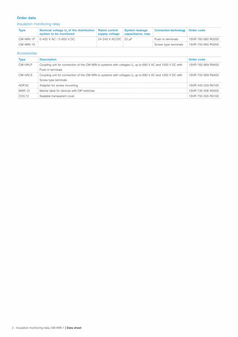
Order data
Insulation monitoring relay
Type Nominal voltage Un of the distribution system to be monitored
Rated control supply voltage
System leakage capacitance, max.
Connection technology Order code
CM-IWN.1P 0-400 V AC / 0-600 V DC 24-240 V AC/DC 20 µF Push-in terminals 1SVR 760 660 R0200
CM-IWN.1S Screw type terminals 1SVR 750 660 R0200
Accessories
Type Description Order code
CM-IVN.P Coupling unit for connection of the CM-IWN to systems with voltages Un up to 690 V AC and 1000 V DC with
Push-in terminals
1SVR 760 669 R9400
CM-IVN.S Coupling unit for connection of the CM-IWN to systems with voltages Un up to 690 V AC and 1000 V DC with
Screw type terminals
1SVR 750 669 R9400
ADP.02 Adapter for screw mounting 1SVR 440 029 R0100
MAR.12 Marker label for devices with DIP switches 1SVR 730 006 R0000
COV.12 Sealable transparent cover 1SVR 750 005 R0100
Data sheet | Insulation monitoring relay CM-IWN.1 - 3
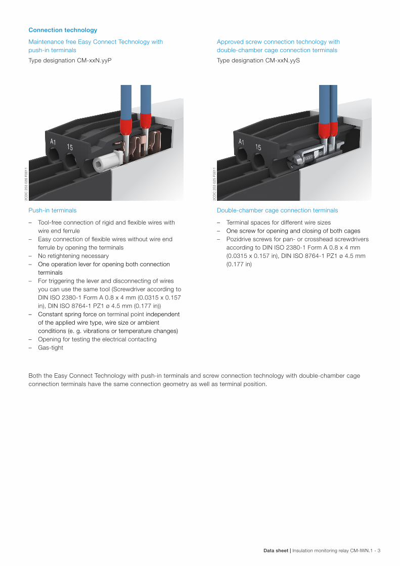
Connection technology
Maintenance free Easy Connect Technology with push-in terminals
Type designation CM-xxN.yyP
Approved screw connection technology with double-chamber cage connection terminals
Type designation CM-xxN.yyS
Push-in terminals
– Tool-free connection of rigid and flexible wires with wire end ferrule
– Easy connection of flexible wires without wire end ferrule by opening the terminals
– No retightening necessary – One operation lever for opening both connection
terminals – For triggering the lever and disconnecting of wires
you can use the same tool (Screwdriver according to DIN ISO 2380-1 Form A 0.8 x 4 mm (0.0315 x 0.157 in), DIN ISO 8764-1 PZ1 ø 4.5 mm (0.177 in))
– Constant spring force on terminal point independent of the applied wire type, wire size or ambient conditions (e. g. vibrations or temperature changes)
– Opening for testing the electrical contacting – Gas-tight
Double-chamber cage connection terminals
– Terminal spaces for different wire sizes – One screw for opening and closing of both cages – Pozidrive screws for pan- or crosshead screwdrivers
according to DIN ISO 2380-1 Form A 0.8 x 4 mm (0.0315 x 0.157 in), DIN ISO 8764-1 PZ1 ø 4.5 mm (0.177 in)
Both the Easy Connect Technology with push-in terminals and screw connection technology with double-chamber cage connection terminals have the same connection geometry as well as terminal position.
2CD
C 2
53 0
25 F
0011
2CD
C 2
53 0
26 F
0011
4 - Insulation monitoring relay CM-IWN.1 | Data sheet
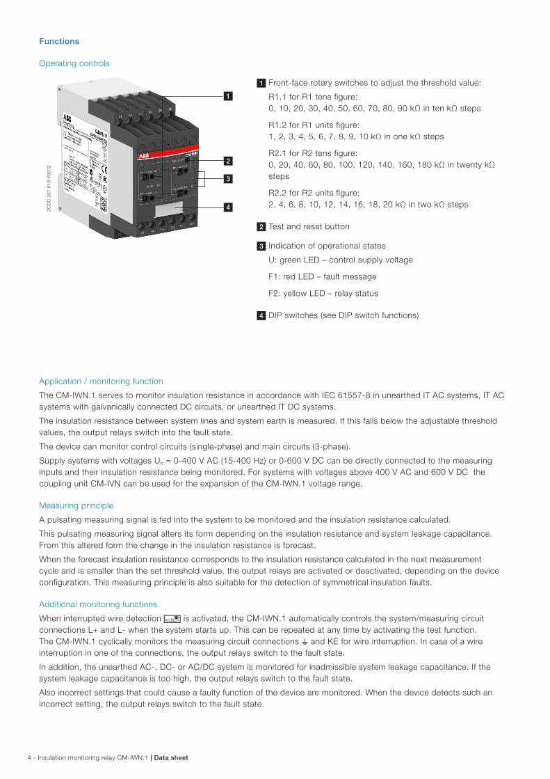
Functions
Operating controls
2CD
C 2
51 0
18 V
0012
1 Front-face rotary switches to adjust the threshold value:
R1.1 for R1 tens figure: 0, 10, 20, 30, 40, 50, 60, 70, 80, 90 kΩ in ten kΩ steps
R1.2 for R1 units figure: 1, 2, 3, 4, 5, 6, 7, 8, 9, 10 kΩ in one kΩ steps
R2.1 for R2 tens figure: 0, 20, 40, 60, 80, 100, 120, 140, 160, 180 kΩ in twenty kΩ steps
R2.2 for R2 units figure: 2, 4, 6, 8, 10, 12, 14, 16, 18, 20 kΩ in two kΩ steps
2 Test and reset button
3 Indication of operational states
U: green LED – control supply voltage
F1: red LED – fault message
F2: yellow LED – relay status
4 DIP switches (see DIP switch functions)
Application / monitoring function
The CM-IWN.1 serves to monitor insulation resistance in accordance with IEC 61557-8 in unearthed IT AC systems, IT AC systems with galvanically connected DC circuits, or unearthed IT DC systems.
The insulation resistance between system lines and system earth is measured. If this falls below the adjustable threshold values, the output relays switch into the fault state.
The device can monitor control circuits (single-phase) and main circuits (3-phase).
Supply systems with voltages Un = 0-400 V AC (15-400 Hz) or 0-600 V DC can be directly connected to the measuring inputs and their insulation resistance being monitored. For systems with voltages above 400 V AC and 600 V DC the coupling unit CM-IVN can be used for the expansion of the CM-IWN.1 voltage range.
Measuring principle
A pulsating measuring signal is fed into the system to be monitored and the insulation resistance calculated.
This pulsating measuring signal alters its form depending on the insulation resistance and system leakage capacitance. From this altered form the change in the insulation resistance is forecast.
When the forecast insulation resistance corresponds to the insulation resistance calculated in the next measurement cycle and is smaller than the set threshold value, the output relays are activated or deactivated, depending on the device configuration. This measuring principle is also suitable for the detection of symmetrical insulation faults.
Additional monitoring functions
When interrupted wire detection u is activated, the CM-IWN.1 automatically controls the system/measuring circuit connections L+ and L- when the system starts up. This can be repeated at any time by activating the test function. The CM-IWN.1 cyclically monitors the measuring circuit connections w and KE for wire interruption. In case of a wire interruption in one of the connections, the output relays switch to the fault state.
In addition, the unearthed AC-, DC- or AC/DC system is monitored for inadmissible system leakage capacitance. If the system leakage capacitance is too high, the output relays switch to the fault state.
Also incorrect settings that could cause a faulty function of the device are monitored. When the device detects such an incorrect setting, the output relays switch to the fault state.
1
2
3
4
Data sheet | Insulation monitoring relay CM-IWN.1 - 5
Operating mode
The system to be monitored is connected to terminals L+ and L-. The earth potential is connected to terminals w and KE.
Depending on the setting, the device operates according to the open-circuit principle h (fault state: relay energized) or closed-circuit principle g (fault state: relay de-energized).
Once the control supply voltage has been applied the insulation monitoring relay runs through a system test routine. The system is diagnosed and the settings are tested. If no internal or external faults are found after this test routine is completed, the output relays switch into the operational state.
All operating states are signalled by the front-face LEDs. See table "LEDs, status information and fault messages" on page 10.
Configuration 1 x 2 c/o contacts j (warning)
With this configuration the settings for the threshold value for prewarning (R2) have no influence on the operating function. If the measured value drops below the set threshold value, the output relays switch into the fault state. If the measured value exceeds the threshold value plus hysteresis, the output relays switch back into their original state.
Configuration 2 x 1 c/o contact i (prewarning and warning)
If the measured value drops below the set threshold value for prewarning the second output relay 21-22/24 switches. If the measured value drops below the threshold value warning, the first output relay 11-12/14 switches.
If the measured value exceeds the threshold value for warning plus hysteresis, the first output relay 11-12/14 switches back into its original state. If the measured value exceeds the threshold value for prewarning plus hysteresis, also the second output relay 21-22/24 switches back to its original state.
Test function
The test function is only possible when there is no fault.
By pressing the front-face combined test/reset button a system test routine is executed. The output relays switch to the fault state as long as the test/reset button is pressed, the control contact S1-S3 is closed or the test functions are processed.
The test function can be activated either with the front-face combined test/reset button or with a remote test button connected as shown in the picture.
S2 S3S1
2CD
C 2
52 1
09 F
0009
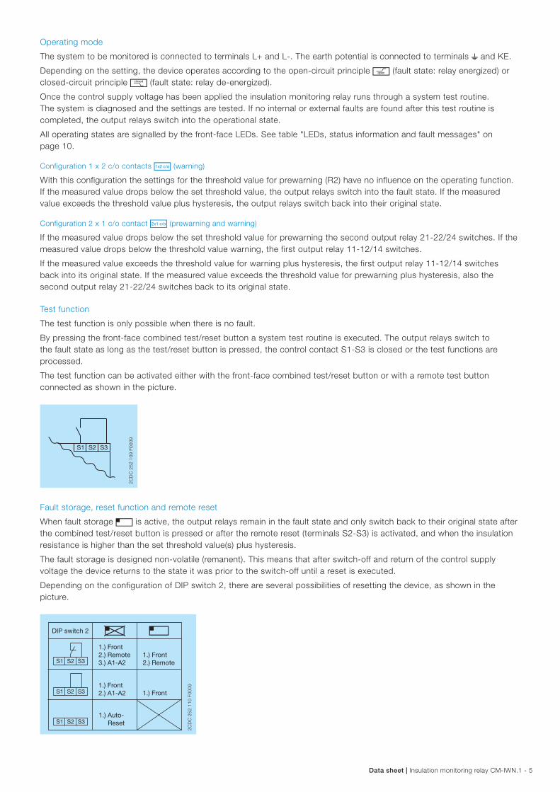
Fault storage, reset function and remote reset
When fault storage f is active, the output relays remain in the fault state and only switch back to their original state after the combined test/reset button is pressed or after the remote reset (terminals S2-S3) is activated, and when the insulation resistance is higher than the set threshold value(s) plus hysteresis.
The fault storage is designed non-volatile (remanent). This means that after switch-off and return of the control supply voltage the device returns to the state it was prior to the switch-off until a reset is executed.
Depending on the configuration of DIP switch 2, there are several possibilities of resetting the device, as shown in the picture.
1.) Auto- Reset
1.) Front
DIP switch 2 e f
S2 S3S1
S2 S3S1
S2 S3S1
1.) Front2.) Remote3.) A1-A2
1.) Front2.) A1-A2
1.) Front2.) Remote
2CD
C 2
52 1
10 F
0009
6 - Insulation monitoring relay CM-IWN.1 | Data sheet
Measuring range expansion by using the coupling unit CM-IVN
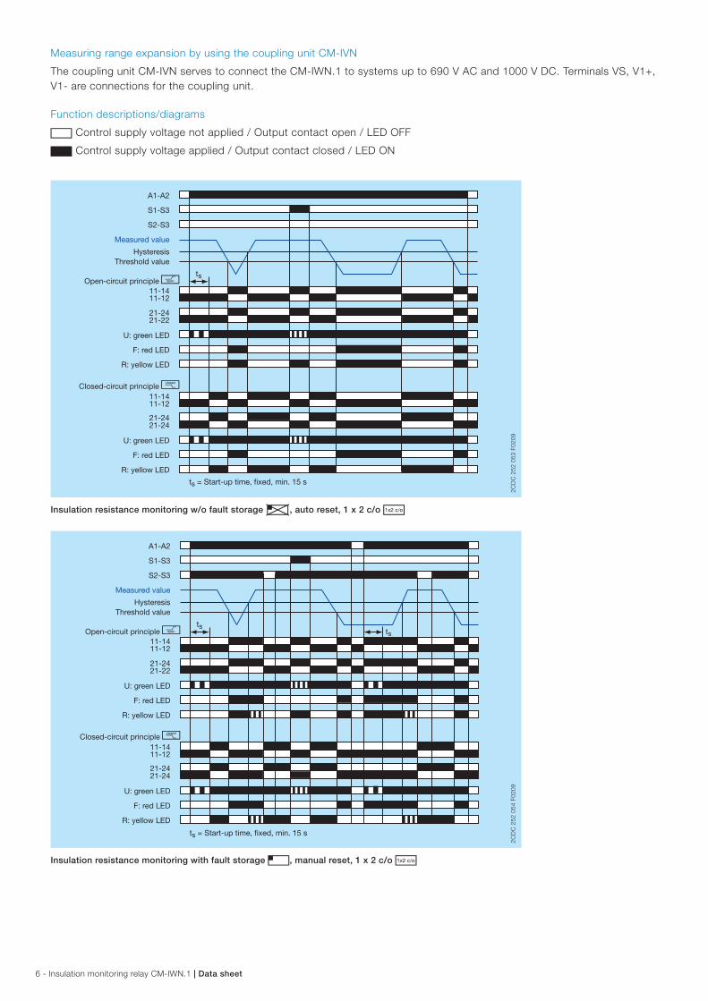
The coupling unit CM-IVN serves to connect the CM-IWN.1 to systems up to 690 V AC and 1000 V DC. Terminals VS, V1+, V1- are connections for the coupling unit.
Function descriptions/diagrams
G Control supply voltage not applied / Output contact open / LED OFF
B Control supply voltage applied / Output contact closed / LED ON
A1-A2
S1-S3
S2-S3
ts
11-1211-14
21-2221-24
11-12
21-24
11-14
21-24
Measured value
HysteresisThreshold value
Open-circuit principle h
U: green LED
F: red LED
R: yellow LED
U: green LED
F: red LED
R: yellow LED
2CD
C 2
52 0
53 F
0209
Closed-circuit principle g
ts = Start-up time, fixed, min. 15 s
2CD
C 2
52 0
53 F
0209
Insulation resistance monitoring w/o fault storage e, auto reset, 1 x 2 c/o j
A1-A2
S1-S3
S2-S3
tsts
11-1211-14
21-2221-24
11-1211-14
21-2421-24
Measured value
HysteresisThreshold value
Open-circuit principle h
U: green LED
F: red LED
R: yellow LED
U: green LED
F: red LED
R: yellow LED
2CD
C 2
52 0
54 F
0209
Closed-circuit principle g
ts = Start-up time, fixed, min. 15 s
2CD
C 2
52 0
54 F
0209
Insulation resistance monitoring with fault storage f, manual reset, 1 x 2 c/o j
Data sheet | Insulation monitoring relay CM-IWN.1 - 7
A1-A2
S1-S3
S2-S3
ts
11-1211-14
21-2221-24
11-1211-14
21-2421-24
Measured value
HysteresisPrewarning
HysteresisWarning
Open-circuit principle h
U: green LED
F: red LED
R: yellow LED
U: green LED
F: red LED
R: yellow LED
2C
DC
252
055
F02
09
Closed-circuit principle g
ts = Start-up time, fixed, min. 15 s
2CD
C 2
52 0
55 F
0209
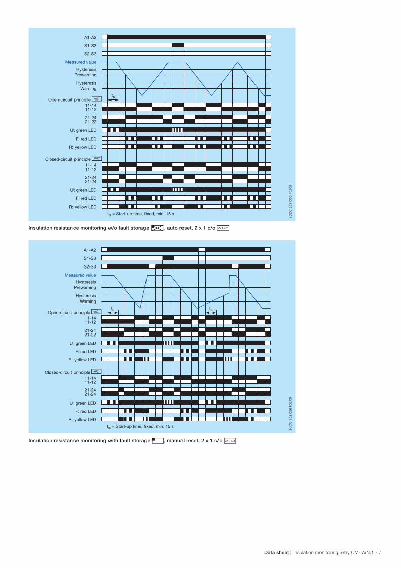
Insulation resistance monitoring w/o fault storage e, auto reset, 2 x 1 c/o i
A1-A2
S1-S3
S2-S3
ts ts
11-1211-14
21-2221-24
11-1211-14
21-2421-24
Measured value
HysteresisPrewarning
HysteresisWarning
Open-circuit principle h
U: green LED
F: red LED
R: yellow LED
U: green LED
F: red LED
R: yellow LED
2C
DC
252
056
F02
09
Closed-circuit principle g
ts = Start-up time, fixed, min. 15 s
2CD
C 2
52 0
56 F
0209
Insulation resistance monitoring with fault storage f, manual reset, 2 x 1 c/o i
8 - Insulation monitoring relay CM-IWN.1 | Data sheet
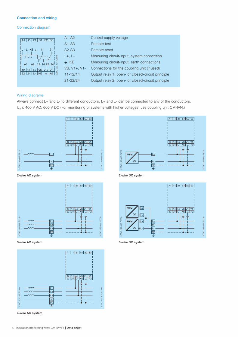
Connection and wiring
Connection diagram
A1 11 S2 S321 S1
wL+ VS12 14
A2V1-V1+
KE wL-
A1
R < w
A2
L+
22 24 L- KE
12 14
11
22 24
21
2C
DC
252
104
F00
09
A1-A2
S1-S3
S2-S3
L+, L–
w, KE
VS, V1+, V1-
11-12/14
21-22/24
Control supply voltage
Remote test
Remote reset
Measuring circuit/input, system connection
Measuring circuit/input, earth connections
Connections for the coupling unit (if used)
Output relay 1, open- or closed-circuit principle
Output relay 2, open- or closed-circuit principle
Wiring diagrams
Always connect L+ and L- to different conductors. L+ and L- can be connected to any of the conductors.
Un ≤ 400 V AC; 600 V DC (For monitoring of systems with higher voltages, use coupling unit CM-IVN.)
2CD
C 2
52 0
82 F
0009
L
N
PE
A1 11 S2 S321 S1
wL+ VS12 14
A2V1-V1+
22 24 L- KE
2CD
C 2
52 0
86 F
0009
2-wire AC system
2CD
C 2
52 0
89 F
0009
L1
L2
L3
PE
A1 11 S2 S321 S1
wL+ VS12 14
A2V1-V1+
22 24 L- KE
2CD
C 2
52 0
93 F
0009
3-wire AC system
2CD
C 2
52 0
96 F
0009 L1
L2
L3
N
PE
A1 11 S2 S321 S1
wL+ VS12 14
A2V1-V1+
22 24 L- KE
2CD
C 2
52 1
00 F
0009
4-wire AC system
2CD
C 2
52 0
88 F
0009
PWM
DC
L+
L-
PE
A1 11 S2 S321 S1
wL+ VS12 14
A2V1-V1+
22 24 L- KE
2CD
C 2
52 0
86 F
0009
2-wire DC system
2CD
C 2
52 0
95 F
0009
PWM
PWM
DC
DC
L+L+
M
L-L-
PE
L+
L-
A1 11 S2 S321 S1
wL+ VS12 14
A2V1-V1+
22 24 L- KE
2CD
C 2
52 0
93 F
0009
3-wire DC system
Data sheet | Insulation monitoring relay CM-IWN.1 - 9
Configuration and settings
Rotary switches R1.1, R1.2, R2.1 and R2.2 (threshold values)
By means of four separate 10 position rotary switches with direct reading scales, the threshold values for the insulation resistance RF of the systems to be monitored can be adjusted.
With the Rx.1 rotary switch the tens figure is set and with the Rx.2 rotary switch the units figure is set. The set threshold value is then the addition of the two values. For example, R1.1 set to 70 and R1.2 set to 8 leads to a threshold value for R1 of 78 kΩ.
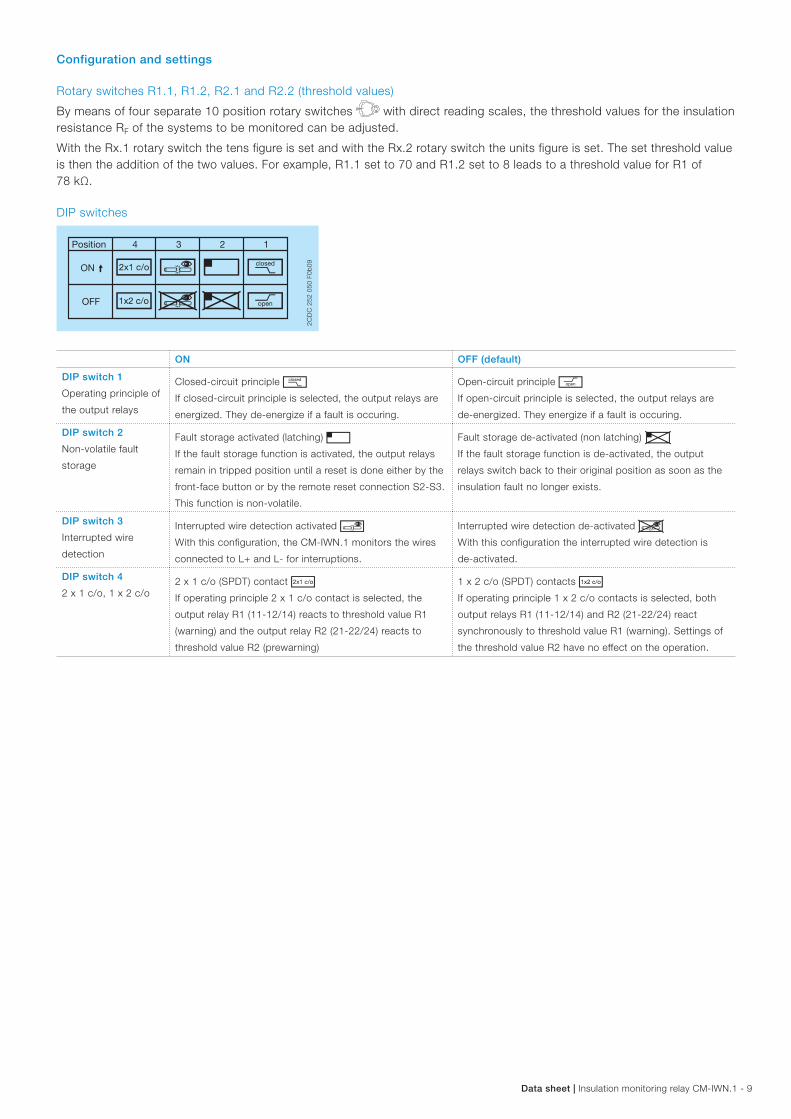
DIP switches
Position 4 123
ON
OFF
i u f ghevj
2CD
C 2
52 0
50 F
0b09
ON OFF (default)
DIP switch 1
Operating principle of
the output relays
Closed-circuit principle gIf closed-circuit principle is selected, the output relays are
energized. They de-energize if a fault is occuring.
Open-circuit principle hIf open-circuit principle is selected, the output relays are
de-energized. They energize if a fault is occuring.
DIP switch 2
Non-volatile fault
storage
Fault storage activated (latching) fIf the fault storage function is activated, the output relays
remain in tripped position until a reset is done either by the
front-face button or by the remote reset connection S2-S3.
This function is non-volatile.
Fault storage de-activated (non latching) eIf the fault storage function is de-activated, the output
relays switch back to their original position as soon as the
insulation fault no longer exists.
DIP switch 3
Interrupted wire
detection
Interrupted wire detection activated uWith this configuration, the CM-IWN.1 monitors the wires
connected to L+ and L- for interruptions.
Interrupted wire detection de-activated vWith this configuration the interrupted wire detection is
de-activated.
DIP switch 4
2 x 1 c/o, 1 x 2 c/o2 x 1 c/o (SPDT) contact iIf operating principle 2 x 1 c/o contact is selected, the
output relay R1 (11-12/14) reacts to threshold value R1
(warning) and the output relay R2 (21-22/24) reacts to
threshold value R2 (prewarning)
1 x 2 c/o (SPDT) contacts jIf operating principle 1 x 2 c/o contacts is selected, both
output relays R1 (11-12/14) and R2 (21-22/24) react
synchronously to threshold value R1 (warning). Settings of
the threshold value R2 have no effect on the operation.
10 - Insulation monitoring relay CM-IWN.1 | Data sheet
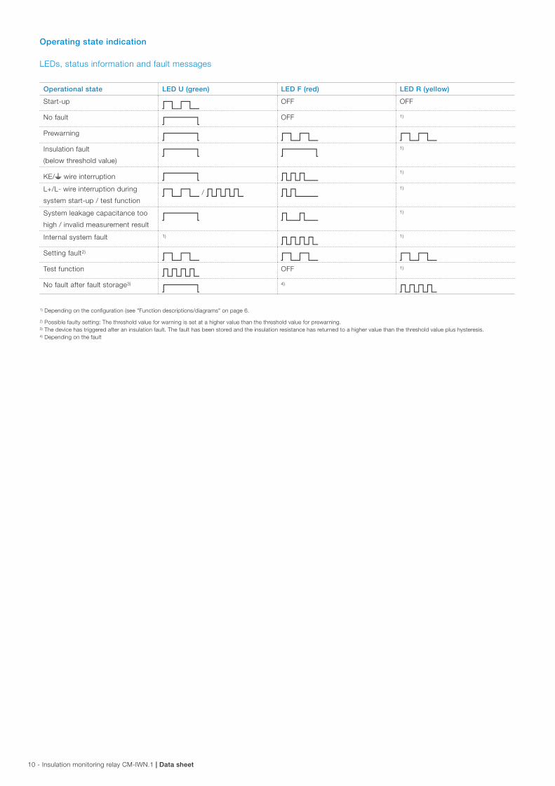
Operating state indication
LEDs, status information and fault messages
Operational state LED U (green) LED F (red) LED R (yellow)
Start-up W OFF OFF
No fault V OFF 1)
Prewarning V W WInsulation fault
(below threshold value)V V
1)
KE/w wire interruption V U1)
L+/L- wire interruption during
system start-up / test functionW / X S
1)
System leakage capacitance too
high / invalid measurement resultV T
1)
Internal system fault 1)
X1)
Setting fault2)
W W WTest function X OFF 1)
No fault after fault storage3)
V4)
X
1) Depending on the configuration (see "Function descriptions/diagrams" on page 6.
2) Possible faulty setting: The threshold value for warning is set at a higher value than the threshold value for prewarning.3) The device has triggered after an insulation fault. The fault has been stored and the insulation resistance has returned to a higher value than the threshold value plus hysteresis.4) Depending on the fault
Data sheet | Insulation monitoring relay CM-IWN.1 - 11
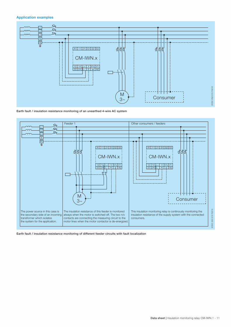
Application examples
L1
L2
L3
N
PE
M
A1 11 S2 S321 S1
L+ V12 14A2V1-V1+
22 24 L- K
Consumer3~
w
CM-IWN.x
2CD
C 2
52 0
15 F
0210
Earth fault / insulation resistance monitoring of an unearthed 4-wire AC system
L1
L2
L3
N
PE
ConsumerM3~
A1 11 S2 S321 S1
L+ V12 14A2V1-V1+
22 24 L- K w
A1 11 S2 S321 S1
L+ V12 14A2V1-V1+
22 24 L- K w
Feeder 1
The insulation resistance of this feeder is monitoredalways when the motor is switched off. The two n/ccontacts are connecting the measuring circuit to the motor lines when the motor contactor is de-energized.
This insulation monitoring relay is continously monitoring the insulation resistance of the supply system with the connected consumers.
The power source in this case is the secondary side of an incomingtransformer which isolates the system for the application.
Other consumers / feeders
CM-IWN.x CM-IWN.x
2CD
C 2
52 0
13 F
0210
Earth fault / insulation resistance monitoring of different feeder circuits with fault localization
12 - Insulation monitoring relay CM-IWN.1 | Data sheet
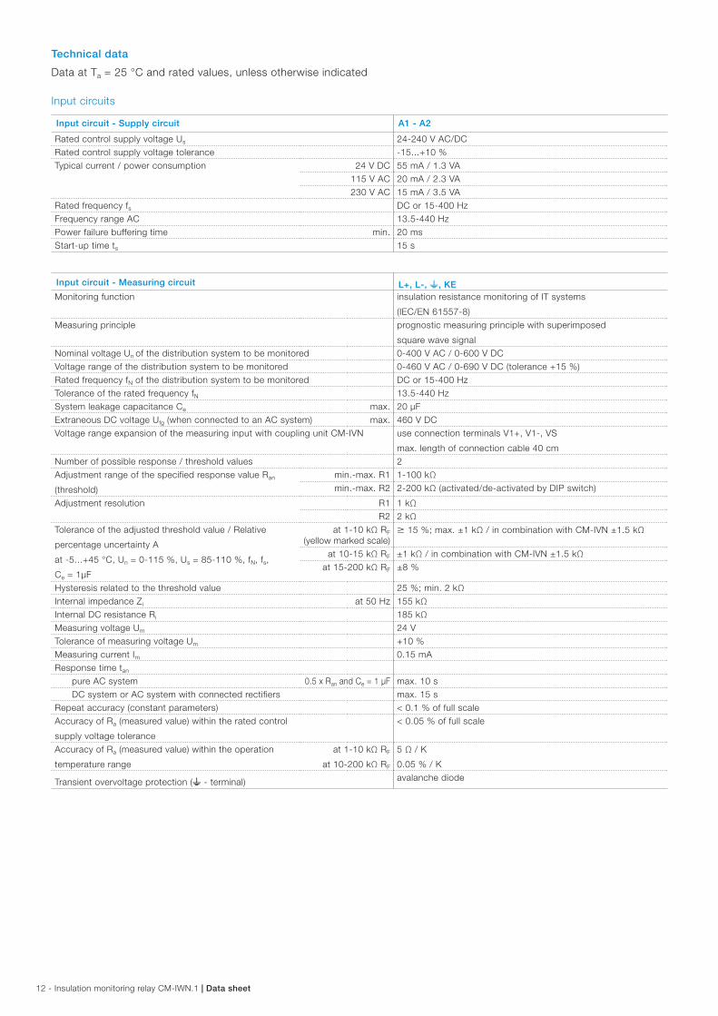
Technical data
Data at Ta = 25 °C and rated values, unless otherwise indicated
Input circuits
Input circuit - Supply circuit A1 - A2
Rated control supply voltage Us 24-240 V AC/DC Rated control supply voltage tolerance -15...+10 %Typical current / power consumption 24 V DC 55 mA / 1.3 VA
115 V AC 20 mA / 2.3 VA230 V AC 15 mA / 3.5 VA
Rated frequency fs DC or 15-400 HzFrequency range AC 13.5-440 HzPower failure buffering time min. 20 msStart-up time ts 15 s
Input circuit - Measuring circuit L+, L-, w, KEMonitoring function insulation resistance monitoring of IT systems
(IEC/EN 61557-8)Measuring principle prognostic measuring principle with superimposed
square wave signal Nominal voltage Un of the distribution system to be monitored 0-400 V AC / 0-600 V DCVoltage range of the distribution system to be monitored 0-460 V AC / 0-690 V DC (tolerance +15 %)Rated frequency fN of the distribution system to be monitored DC or 15-400 HzTolerance of the rated frequency fN 13.5-440 HzSystem leakage capacitance Ce max. 20 µFExtraneous DC voltage Ufg (when connected to an AC system) max. 460 V DC Voltage range expansion of the measuring input with coupling unit CM-IVN use connection terminals V1+, V1-, VS
max. length of connection cable 40 cmNumber of possible response / threshold values 2Adjustment range of the specified response value Ran
(threshold)
min.-max. R1 1-100 kΩmin.-max. R2 2-200 kΩ (activated/de-activated by DIP switch)
Adjustment resolution R1 1 kΩR2 2 kΩ
Tolerance of the adjusted threshold value / Relative
percentage uncertainty A
at -5...+45 °C, Un = 0-115 %, Us = 85-110 %, fN, fs,
Ce = 1µF
at 1-10 kΩ RF
(yellow marked scale)M 15 %; max. ±1 kΩ / in combination with CM-IVN ±1.5 kΩ
at 10-15 kΩ RF ±1 kΩ / in combination with CM-IVN ±1.5 kΩat 15-200 kΩ RF ±8 %
Hysteresis related to the threshold value 25 %; min. 2 kΩInternal impedance Zi at 50 Hz 155 kΩInternal DC resistance Ri 185 kΩMeasuring voltage Um 24 VTolerance of measuring voltage Um +10 %Measuring current Im 0.15 mAResponse time tan
pure AC system 0.5 x Ran and Ce = 1 µF max. 10 sDC system or AC system with connected rectifiers max. 15 s
Repeat accuracy (constant parameters) < 0.1 % of full scaleAccuracy of Ra (measured value) within the rated control
supply voltage tolerance
< 0.05 % of full scale
Accuracy of Ra (measured value) within the operation
temperature range
at 1-10 kΩ RF
at 10-200 kΩ RF
5 Ω / K
0.05 % / K
Transient overvoltage protection (w - terminal) avalanche diode
Data sheet | Insulation monitoring relay CM-IWN.1 - 13
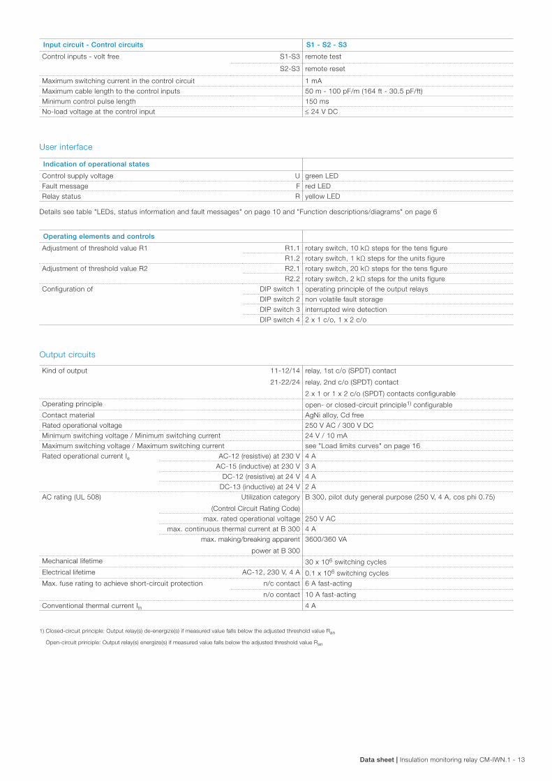
Input circuit - Control circuits S1 - S2 - S3
Control inputs - volt free S1-S3 remote test
S2-S3 remote reset
Maximum switching current in the control circuit 1 mAMaximum cable length to the control inputs 50 m - 100 pF/m (164 ft - 30.5 pF/ft)Minimum control pulse length 150 msNo-load voltage at the control input ≤ 24 V DC
User interface
Indication of operational states
Control supply voltage U green LEDFault message F red LEDRelay status R yellow LED
Details see table "LEDs, status information and fault messages" on page 10 and "Function descriptions/diagrams" on page 6
Operating elements and controls
Adjustment of threshold value R1 R1.1 rotary switch, 10 kΩ steps for the tens figureR1.2 rotary switch, 1 kΩ steps for the units figure
Adjustment of threshold value R2 R2.1 rotary switch, 20 kΩ steps for the tens figureR2.2 rotary switch, 2 kΩ steps for the units figure
Configuration of DIP switch 1 operating principle of the output relaysDIP switch 2 non volatile fault storageDIP switch 3 interrupted wire detectionDIP switch 4 2 x 1 c/o, 1 x 2 c/o
Output circuits
Kind of output 11-12/14
21-22/24
relay, 1st c/o (SPDT) contact
relay, 2nd c/o (SPDT) contact
2 x 1 or 1 x 2 c/o (SPDT) contacts configurable Operating principle open- or closed-circuit principle1) configurableContact material AgNi alloy, Cd freeRated operational voltage 250 V AC / 300 V DCMinimum switching voltage / Minimum switching current 24 V / 10 mAMaximum switching voltage / Maximum switching current see "Load limits curves" on page 16Rated operational current Ie AC-12 (resistive) at 230 V 4 A
AC-15 (inductive) at 230 V 3 ADC-12 (resistive) at 24 V 4 A
DC-13 (inductive) at 24 V 2 AAC rating (UL 508) Utilization category
(Control Circuit Rating Code)
B 300, pilot duty general purpose (250 V, 4 A, cos phi 0.75)
max. rated operational voltage 250 V ACmax. continuous thermal current at B 300 4 A
max. making/breaking apparent
power at B 300
3600/360 VA
Mechanical lifetime 30 x 106 switching cyclesElectrical lifetime AC-12, 230 V, 4 A 0.1 x 10⁶ switching cyclesMax. fuse rating to achieve short-circuit protection n/c contact 6 A fast-acting
n/o contact 10 A fast-acting
Conventional thermal current Ith 4 A
1) Closed-circuit principle: Output relay(s) de-energize(s) if measured value falls below the adjusted threshold value Ran
Open-circuit principle: Output relay(s) energize(s) if measured value falls below the adjusted threshold value Ran
14 - Insulation monitoring relay CM-IWN.1 | Data sheet
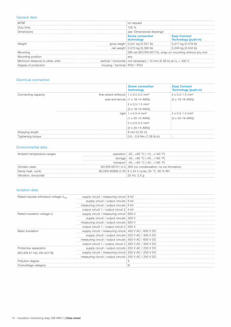
General data
MTBF on request
Duty time 100 %Dimensions see ‘Dimensional drawings’
Screw connection technology
Easy Connect Technology (push-in)
Weight gross weight 0,241 kg (0.531 lb) 0,217 kg (0.478 lb)net weight 0.270 kg (0.595 lb) 0.246 kg (0.542 lb)
Mounting DIN rail (IEC/EN 60715), snap-on mounting without any toolMounting position anyMinimum distance to other units vertical / horizontal not necessary / 10 mm (0.39 in) at Un > 400 V Degree of protection housing / terminal IP50 / IP20
Electrical connection
Screw connection technology
Easy Connect Technology (push-in)
Connecting capacity fine-strand with(out)
wire end ferrule
1 x 0.5-2.5 mm²
(1 x 18-14 AWG)
2 x 0.5-1.5 mm²
(2 x 18-16 AWG)
2 x 0.5-1.5 mm²
(2 x 18-16 AWG)
rigid 1 x 0.5-4 mm²
(1 x 20-12 AWG)
2 x 0.5-2.5 mm²
(2 x 20-14 AWG)
2 x 0.5-1.5 mm²
(2 x 20-16 AWG)
Stripping length 8 mm (0.32 in)Tightening torque 0.6 - 0.8 Nm (7.08 lb.in) -
Environmental data
Ambient temperature ranges operation -25...+60 °C (-13...+140 °F)storage -40...+85 °C (-40...+185 °F)
transport -40...+85 °C (-40...+185 °F)Climatic class IEC/EN 60721-3-3 3K5 (no condensation, no ice formation)Damp heat, cyclic IEC/EN 60068-2-30 6 x 24 h cycle, 55 °C, 95 % RHVibration, sinusoidal 25 Hz: 2.5 g
Isolation data
Rated impulse withstand voltage Uimp supply circuit / measuring circuit 6 kVsupply circuit / output circuits 6 kV
measuring circuit / output circuits 6 kVoutput circuit 1 / output circuit 2 4 kV
Rated insulation voltage Ui supply circuit / measuring circuit 600 Vsupply circuit / output circuits 300 V
measuring circuit / output circuits 600 Voutput circuit 1 / output circuit 2 300 V
Basic insulation supply circuit / measuring circuit 400 V AC / 600 V DCsupply circuit / output circuits 250 V AC / 300 V DC
measuring circuit / output circuits 400 V AC / 600 V DCoutput circuit 1 / output circuit 2 250 V AC / 300 V DC
Protective separation
(IEC/EN 61140, EN 50178)
supply circuit / output circuits 250 V AC / 250 V DCsupply circuit / measuring circuit 250 V AC / 250 V DC
measuring circuit / output circuits 250 V AC / 250 V DCPollution degree 3Overvoltage category III
Data sheet | Insulation monitoring relay CM-IWN.1 - 15
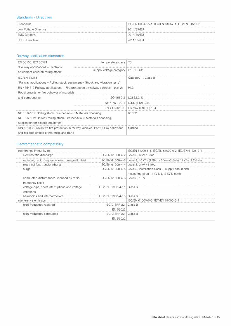
Standards / Directives
Standards IEC/EN 60947-5-1, IEC/EN 61557-1, IEC/EN 61557-8
Low Voltage Directive 2014/35/EU
EMC Directive 2014/30/EU
RoHS Directive 2011/65/EU
Railway application standards
EN 50155, IEC 60571
“Railway applications – Electronic
equipment used on rolling stock”
temperature class T3
supply voltage category S1, S2, C2
IEC/EN 61373
“Railway applications – Rolling stock equipment – Shock and vibration tests”
Category 1, Class B
EN 45545-2 Railway applications – Fire protection on railway vehicles – part 2:
Requirements for fire behavior of materials
HL3
and components ISO 4589-2 LOI 32.3 %
NF X-70-100-1 C.I.T. (T12) 0.45
EN ISO 5659-2 Ds max (T10.03) 104
NF F 16-101: Rolling stock. Fire behaviour. Materials choosing
NF F 16-102: Railway rolling stock. Fire behaviour. Materials choosing,
application for electric equipment
I2 / F2
DIN 5510-2 Preventive fire protection in railway vehicles. Part 2: Fire behaviour
and fire side effects of materials and parts
fullfilled
Electromagnetic compatibility
Interference immunity to IEC/EN 61000-6-1, IEC/EN 61000-6-2, IEC/EN 61326-2-4 electrostatic discharge IEC/EN 61000-4-2 Level 3, 6 kV / 8 kV
radiated, radio-frequency, electromagnetic field IEC/EN 61000-4-3 Level 3, 10 V/m (1 GHz) / 3 V/m (2 GHz) / 1 V/m (2.7 GHz)electrical fast transient/burst IEC/EN 61000-4-4 Level 3, 2 kV / 5 kHzsurge IEC/EN 61000-4-5 Level 3, installation class 3, supply circuit and
measuring circuit 1 kV L-L, 2 kV L-earth conducted disturbances, induced by radio-
frequency fields
IEC/EN 61000-4-6 Level 3, 10 V
voltage dips, short interruptions and voltage
variations
IEC/EN 61000-4-11 Class 3
harmonics and interharmonics IEC/EN 61000-4-13 Class 3Interference emission IEC/EN 61000-6-3, IEC/EN 61000-6-4
high-frequency radiated IEC/CISPR 22,
EN 55022
Class B
high-frequency conducted IEC/CISPR 22,
EN 55022
Class B
16 - Insulation monitoring relay CM-IWN.1 | Data sheet
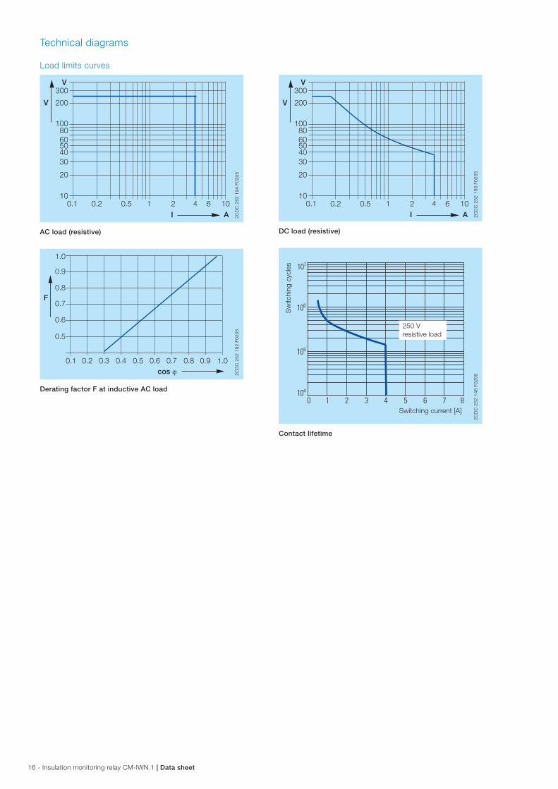
Technical diagrams
Load limits curves
300
200
1008060504030
20
101 2 4 6 10
I A
V
V
0.1 0.2 0.5
2CD
C 2
52 1
94 F
0205
AC load (resistive)
cos ϕ
F
0.5
0.1 0.2 0.3 0.4 0.5 0.6 0.7 0.8 0.9 1.0
0.6
0.7
0.8
0.9
1.0
2CD
C 2
52 1
92 F
0205
Derating factor F at inductive AC load
300
200
1008060504030
20
101 2 4 6 10
I A
V
V
0.1 0.2 0.5
2CD
C 2
52 1
93 F
0205
DC load (resistive)
Switching current [A]
250 Vresistive load
Sw
itchi
ng c
ycle
s
2CD
C 2
52 1
48 F
0206
Contact lifetime
Data sheet | Insulation monitoring relay CM-IWN.1 - 17
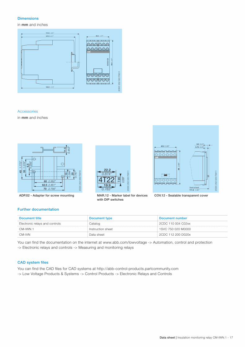
Dimensions
in mm and inches
114.5 4.51”
45.0 1.77”
85.6
3.37
”
104.8 4.13”
107.0 4.21”
2CD
C 2
52 0
22 F
0011
Accessories
in mm and inches
45.0 0.89”
68 2.68
”
111.8 4.40”
9.3 0.37”
5.75 0.23”
front to back
2CD
C 2
52 0
23 F
0011
6.5
62.560
1011
.5
20
0.25
6”
351.37
8”
451.77
2”
2.461”
70 2.756”
2.362”
0.39
4”
0.78
7”
0.45
3”
2CD
C 2
52 0
09 F
0010
19.94T22 7.
850.30
9”
0.783”
22.20.874”
2CD
C 2
52 0
20 F
0011
ADP.02 - Adapter for screw mounting MAR.12 - Marker label for devices with DIP switches
COV.12 - Sealable transparent cover
Further documentation
Document title Document type Document number
Electronic relays and controls Catalog 2CDC 110 004 C02xx
CM-IWN.1 Instruction sheet 1SVC 750 020 M0000
CM-IVN Data sheet 2CDC 112 200 D020x
You can find the documentation on the internet at www.abb.com/lowvoltage -> Automation, control and protection -> Electronic relays and controls -> Measuring and monitoring relays
CAD system files
You can find the CAD files for CAD systems at http://abb-control-products.partcommunity.com -> Low Voltage Products & Systems -> Control Products -> Electronic Relays and Controls
ABB STOTZ-KONTAKT GmbHP. O. Box 10 16 8069006 Heidelberg, GermanyPhone: +49 (0) 6221 7 01-0Fax: +49 (0) 6221 7 01-13 25E-mail: [email protected]
You can find the address of your local sales organisation on the ABB home pagehttp://www.abb.com/contacts -> Low Voltage Products and Systems
Contact us
Note:We reserve the right to make technical changes or modify the contents of this document without prior notice. With regard to purchase orders, the agreed particulars shall prevail. ABB AG does not accept any responsibility whatsoever for potential errors or possible lack of information in this document.
We reserve all rights in this document and in the subject matter and illustrations contained therein. Any reproduction, disclosure to third parties or utilization of its contents – in whole or in parts – is forbidden without prior written consent of ABB AG.
Copyright© 2017 ABB All rights reserved
Do
cum
ent
num
ber
2C
DC
112
198
D02
01 (0
1.20
17)