Embed Size (px)
Citation preview
lable at ScienceDirect
Intermetallics 16 (2008) 1083–1089
Contents lists avai
Intermetallics
journal homepage: www.elsevier .com/locate/ intermet
Infrared brazing of Ti50Al50 and Ti–6Al–4V using two Ti-based filler metals
R.K. Shiue, S.K. Wu*, Y.T. Chen, C.Y. ShiueDepartment of Materials Science and Engineering, National Taiwan University, Taipei 106, Taiwan
a r t i c l e i n f o
Article history:Received 22 February 2008Received in revised form 2 June 2008Accepted 19 June 2008
Keywords:A. Titanium aluminides, based on TiAlB. BondingC. JoiningF. Electron microscopy, scanningG. Aerospace constructional uses
* Corresponding author. Tel.: þ886 2 2363 7846; faE-mail address: [email protected] (S.K. Wu).
0966-9795/$ – see front matter � 2008 Elsevier Ltd.doi:10.1016/j.intermet.2008.06.007
a b s t r a c t
Infrared brazing of Ti50Al50 and Ti–6Al–4V using Ti–15Cu–25Ni and Ti–15Cu–15Ni braze alloys has beenconducted. The joint mainly consists of Ti-rich, Ti2Ni and interfacial Ti3Al phases. The amount of Ti2Ni isdecreased with increasing the brazing temperature and/or time due to the diffusion of Ni from the brazealloy into the Ti–6Al–4V substrate during brazing. In contrast, the thickness of interfacial Ti3Al phase isinsensitive to infrared brazing conditions. The interfacial Ti3Al is primarily formed during the coolingcycle of brazing due to limited solubilities of Al, Cu and Ni in a-Ti. The presence of both Ti2Ni andinterfacial Ti3Al phases deteriorates shear strength of the joint. The specimen using Ti–15Cu–15Ni brazealloy demonstrates the best bonding strength of the joint infrared brazed at 970 �C above 600 s.
� 2008 Elsevier Ltd. All rights reserved.
1. Introduction successfully applied in brazing the Ti-based alloys [9–12]. However,
Table 1Summary of infrared brazing variables used in the experiment
Filler metal Brazing time (s)/temp. 930 �C 950 �C 970 �C
Ti–15Cu–25Ni 180 M M300 M M S/M600 M900 S/M
Ti–15Cu–15Ni 180 M300 M S/M
The demand of advanced structural alloys for aerospace andautomotive applications has pushed the development ofintermetallic compounds [1,2]. Compared to titanium alloys, TiAl-based intermetallics are featured with low density, high specificstrength, stiffness and creep strength at elevated temperatures [3,4].They have been regarded as the potential replacement for titaniumalloys in the aircraft compressor. The production cost of TiAl-basedintermetallics is high, so bonding of the TiAl-based intermetalliccompound and dissimilar structural alloy such as the titanium alloyis crucial in the application of the TiAl-based intermetallics.
Since that the titanium alloy is characterized with high specificstrength and excellent corrosion resistance, it is particularly suit-able for the aerospace application [5]. Ti–6Al–4V is one of the mostimportant a–b titanium alloys, which can be strengthened byproper heat treatments [5]. However, the joining of TiAl-basedintermetallics, e.g., Ti50Al50, and Ti–6Al–4V alloy is difficult due tohigh reactivity of these alloys. The formation of brittle oxides aswell as intermetallic compounds in the joint can causedeterioration of the bonding strength [6–8]. Therefore, greatcaution must be taken in joining these alloys. For example, thejoining process should be performed under a vacuum or protectiveatmosphere in order to avoid oxygen contamination. Accordingly,vacuum brazing has been considered one of the most promisingapproaches in brazing these alloys [5].
The selection of brazing filler metals is also important in brazingTi50Al50 and Ti–6Al–4V. Many Ag-based braze alloys are
x: þ886 2 2363 4562.
All rights reserved.
most Ag-based braze alloys have low tensile strength and limitedcreep strength above 400 �C as compared with the Ti-based brazealloys [7]. In contrast, Ti–Cu–Ni filler foils demonstrate excellentbonding performance in brazing many titanium alloys [13–15].Both Ti–15Cu–25Ni and Ti–15Cu–15Ni in wt% were chosen to brazeTi50Al50 and Ti–6Al–4V in the experiment.
Infrared vacuum brazing is characterized by its high heating rateup to 50 �C/s. It has been proven to be a useful method toinvestigate the microstructural evolution of the brazed joint in theprevious studies [9,10,14,15]. Both the microstructural evolutionand shear strength of infrared brazed Ti50Al50 and Ti–6Al–4V jointsusing two Ti-based braze alloys were evaluated in the study.
2. Experimental procedures
The base metals used in the experiment were Ti50Al50 andTi–6Al–4V plates with a thickness of 3 mm each. Ti50Al50 wasprepared by vacuum arc-remelter of high purity (>99.99 wt%)
600 S/M1200 S/M
S: shear test specimen, M: metallographic specimen.
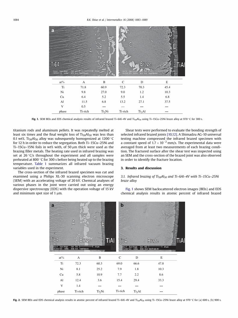
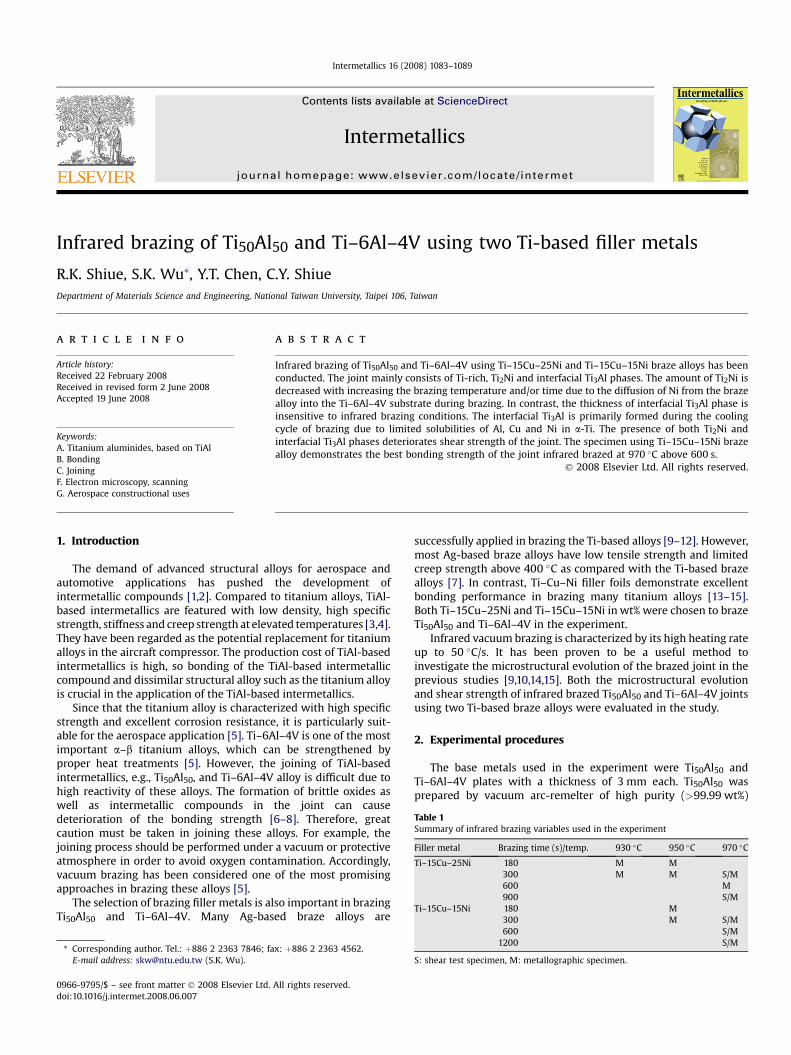
A B C D E
Ti 71.8 60.9 72.3 70.3 45.4
Ni 9.8 27.0 9.0 1.2 10.3
Cu 6.4 5.2 5.5 1.4 6.8
Al 11.5 6.8 13.2 27.1 37.5
V 0.5 --- --- --- ---
phase Ti-rich Ti2Ni Ti-rich Ti3Al ---
a b
at
Fig. 1. SEM BEIs and EDS chemical analysis results of infrared brazed Ti–6Al–4V and Ti50Al50 using Ti–15Cu–25Ni braze alloy at 970 �C for 300 s.
R.K. Shiue et al. / Intermetallics 16 (2008) 1083–10891084
titanium rods and aluminum pellets. It was repeatedly melted atleast six times and the final weight loss of Ti50Al50 was less than0.1 wt%. Ti50Al50 alloy was subsequently homogenized at 1200 �Cfor 12 h in order to reduce the segregation. Both Ti–15Cu–25Ni andTi–15Cu–15Ni foils in wt% with, of 50 mm thick were used as thebrazing filler metals. The heating rate used in infrared brazing wasset at 26 �C/s throughout the experiment and all samples werepreheated at 800 �C for 300 s before being heated up to the brazingtemperature. Table 1 summarizes all infrared vacuum brazingvariables used in the experiment.
The cross-section of the infrared brazed specimen was cut andexamined using a Philips XL-30 scanning electron microscope(SEM) with an accelerating voltage of 20 kV. Chemical analyses ofvarious phases in the joint were carried out using an energydispersive spectroscopy (EDS) with the operation voltage of 15 kVand minimum spot size of 1 mm.
A B C
Ti 72.3 60.3 69
Ni 8.1 25.2 7.
Cu 5.8 10.9 7.
Al 12.4 3.6 15
V 1.4 --- --
phase Ti-rich Ti2Ni Ti-
a
at
Fig. 2. SEM BEIs and EDS chemical analysis results in atomic percent of infrared brazed Ti–
Shear tests were performed to evaluate the bonding strength ofselected infrared brazed joints [10,12]. A Shimadzu AG-10 universaltesting machine compressed the infrared brazed specimen witha constant speed of 1.7�10�2 mm/s. The experimental data wereaveraged from at least two measurements of each brazing condi-tion. The fractured surface after the shear test was inspected usingan SEM and the cross-section of the brazed joint was also observedin order to identify the fracture location.
3. Results and discussion
3.1. Infrared brazing of Ti50Al50 and Ti–6Al–4V with Ti–15Cu–25Nibraze alloy
Fig. 1 shows SEM backscattered electron images (BEIs) and EDSchemical analysis results in atomic percent of infrared brazed
D E
.0 66.6 47.8
9 1.8 10.3
7 2.2 8.6
.4 29.4 33.3
- --- ---
rich Ti3Al ---
b
6Al–4V and Ti50Al50 using Ti–15Cu–25Ni braze alloy at 970 �C for (a) 600 s, (b) 900 s.
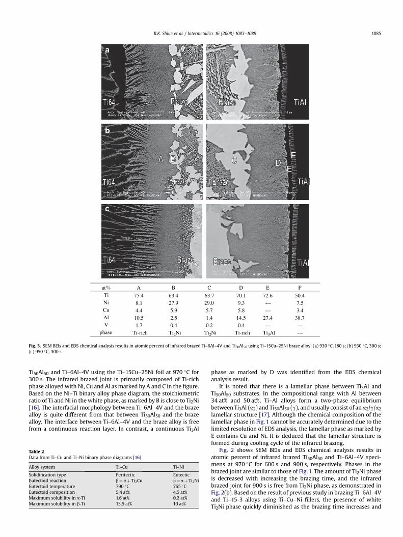
ATi 75.4 63.4 63.7 70.1 72.6 50.4Ni 8.1 27.9 29.0 9.3 --- 7.5Cu 4.4 5.9 5.7 5.8 --- 3.4Al 10.5 2.5 1.4 14.5 27.4 38.7V 1.7 0.4 0.2 0.4 --- ---
phase Ti-rich Ti2Ni Ti2Ni Ti-rich Ti3Al ---
B C D E Fat
a
b
c
Fig. 3. SEM BEIs and EDS chemical analysis results in atomic percent of infrared brazed Ti–6Al–4V and Ti50Al50 using Ti–15Cu–25Ni braze alloy: (a) 930 �C, 180 s; (b) 930 �C, 300 s;(c) 950 �C, 300 s.
R.K. Shiue et al. / Intermetallics 16 (2008) 1083–1089 1085
Ti50Al50 and Ti–6Al–4V using the Ti–15Cu–25Ni foil at 970 �C for300 s. The infrared brazed joint is primarily composed of Ti-richphase alloyed with Ni, Cu and Al as marked by A and C in the figure.Based on the Ni–Ti binary alloy phase diagram, the stoichiometricratio of Ti and Ni in the white phase, as marked by B is close to Ti2Ni[16]. The interfacial morphology between Ti–6Al–4V and the brazealloy is quite different from that between Ti50Al50 and the brazealloy. The interface between Ti–6Al–4V and the braze alloy is freefrom a continuous reaction layer. In contrast, a continuous Ti3Al
Table 2Data from Ti–Cu and Ti–Ni binary phase diagrams [16]
Alloy system Ti–Cu Ti–Ni
Solidification type Peritectic EutecticEutectoid reaction b¼ aþ Ti2Cu b¼ aþ Ti2NiEutectoid temperature 790 �C 765 �CEutectoid composition 5.4 at% 4.5 at%Maximum solubility in a-Ti 1.6 at% 0.2 at%Maximum solubility in b-Ti 13.5 at% 10 at%
phase as marked by D was identified from the EDS chemicalanalysis result.
It is noted that there is a lamellar phase between Ti3Al andTi50Al50 substrates. In the compositional range with Al between34 at% and 50 at%, Ti–Al alloys form a two-phase equilibriumbetween Ti3Al (a2) and Ti50Al50 (g), and usually consist of an a2/g/a2
lamellar structure [17]. Although the chemical composition of thelamellar phase in Fig. 1 cannot be accurately determined due to thelimited resolution of EDS analysis, the lamellar phase as marked byE contains Cu and Ni. It is deduced that the lamellar structure isformed during cooling cycle of the infrared brazing.
Fig. 2 shows SEM BEIs and EDS chemical analysis results inatomic percent of infrared brazed Ti50Al50 and Ti–6Al–4V speci-mens at 970 �C for 600 s and 900 s, respectively. Phases in thebrazed joint are similar to those of Fig. 1. The amount of Ti2Ni phaseis decreased with increasing the brazing time, and the infraredbrazed joint for 900 s is free from Ti2Ni phase, as demonstrated inFig. 2(b). Based on the result of previous study in brazing Ti–6Al–4Vand Ti–15-3 alloys using Ti–Cu–Ni fillers, the presence of whiteTi2Ni phase quickly diminished as the brazing time increases and
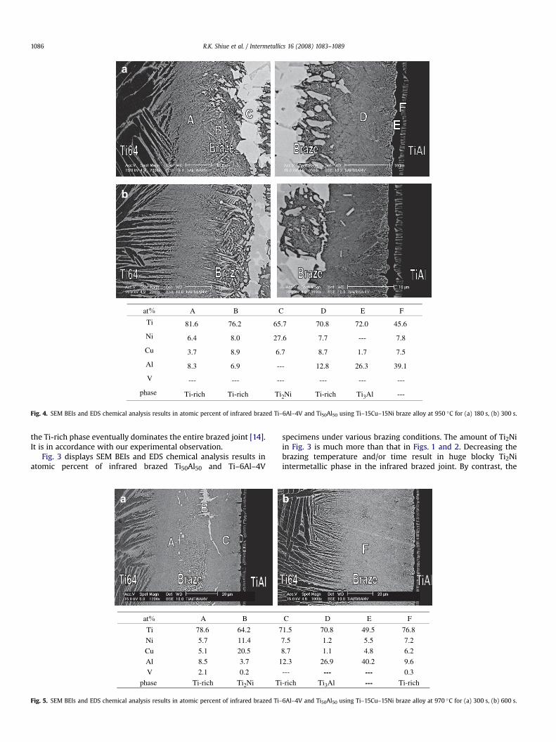
A B C D E F
Ti 81.6 76.2 65.7 70.8 72.0 45.6
Ni 6.4 8.0 27.6 7.7 --- 7.8
Cu 3.7 8.9 6.7 8.7 1.7 7.5
Al 8.3 6.9 --- 12.8 26.3 39.1
V --- --- --- --- --- ---
phase Ti-rich Ti-rich Ti2Ni Ti-rich Ti3Al ---
at
b
a
Fig. 4. SEM BEIs and EDS chemical analysis results in atomic percent of infrared brazed Ti–6Al–4V and Ti50Al50 using Ti–15Cu–15Ni braze alloy at 950 �C for (a) 180 s, (b) 300 s.
R.K. Shiue et al. / Intermetallics 16 (2008) 1083–10891086
the Ti-rich phase eventually dominates the entire brazed joint [14].It is in accordance with our experimental observation.
Fig. 3 displays SEM BEIs and EDS chemical analysis results inatomic percent of infrared brazed Ti50Al50 and Ti–6Al–4V
A B
Ti 78.6 64.2 7
Ni 5.7 11.4
Cu 5.1 20.5
Al 8.5 3.7 1
V 2.1 0.2
phase Ti-rich Ti2Ni T
a
at
Fig. 5. SEM BEIs and EDS chemical analysis results in atomic percent of infrared brazed Ti–
specimens under various brazing conditions. The amount of Ti2Niin Fig. 3 is much more than that in Figs. 1 and 2. Decreasing thebrazing temperature and/or time result in huge blocky Ti2Niintermetallic phase in the infrared brazed joint. By contrast, the
C D E F
1.5 70.8 49.5 76.8
7.5 1.2 5.5 7.2
8.7 1.1 4.8 6.2
2.3 26.9 40.2 9.6
--- --- --- 0.3
i-rich Ti3Al --- Ti-rich
b
6Al–4V and Ti50Al50 using Ti–15Cu–15Ni braze alloy at 970 �C for (a) 300 s, (b) 600 s.
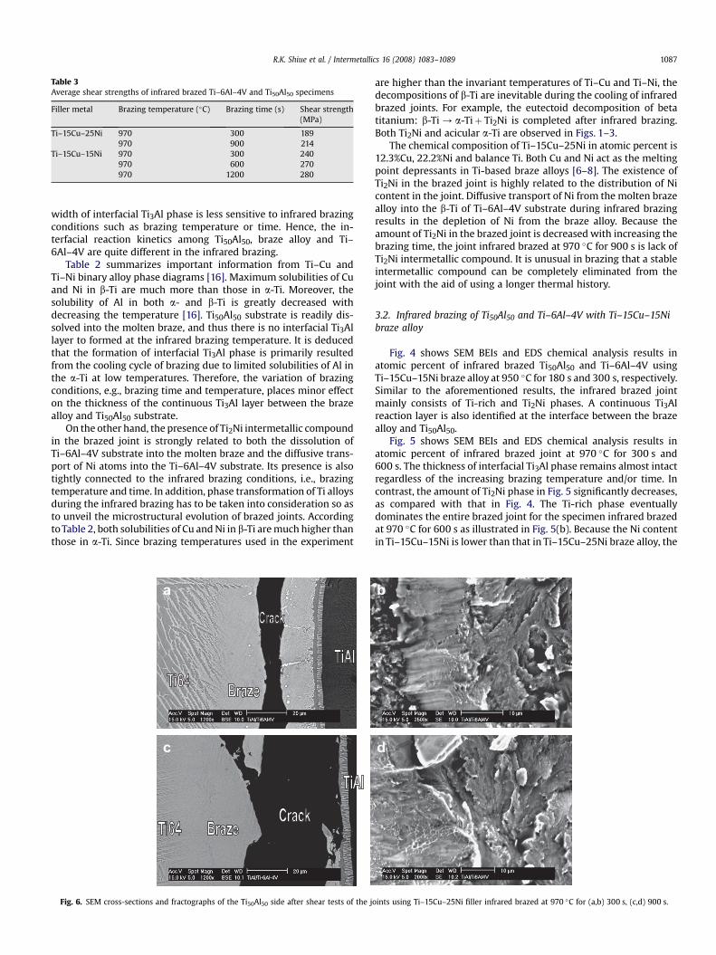
Table 3Average shear strengths of infrared brazed Ti–6Al–4V and Ti50Al50 specimens
Filler metal Brazing temperature (�C) Brazing time (s) Shear strength(MPa)
Ti–15Cu–25Ni 970 300 189970 900 214
Ti–15Cu–15Ni 970 300 240970 600 270970 1200 280
R.K. Shiue et al. / Intermetallics 16 (2008) 1083–1089 1087
width of interfacial Ti3Al phase is less sensitive to infrared brazingconditions such as brazing temperature or time. Hence, the in-terfacial reaction kinetics among Ti50Al50, braze alloy and Ti–6Al–4V are quite different in the infrared brazing.
Table 2 summarizes important information from Ti–Cu andTi–Ni binary alloy phase diagrams [16]. Maximum solubilities of Cuand Ni in b-Ti are much more than those in a-Ti. Moreover, thesolubility of Al in both a- and b-Ti is greatly decreased withdecreasing the temperature [16]. Ti50Al50 substrate is readily dis-solved into the molten braze, and thus there is no interfacial Ti3Allayer to formed at the infrared brazing temperature. It is deducedthat the formation of interfacial Ti3Al phase is primarily resultedfrom the cooling cycle of brazing due to limited solubilities of Al inthe a-Ti at low temperatures. Therefore, the variation of brazingconditions, e.g., brazing time and temperature, places minor effecton the thickness of the continuous Ti3Al layer between the brazealloy and Ti50Al50 substrate.
On the other hand, the presence of Ti2Ni intermetallic compoundin the brazed joint is strongly related to both the dissolution ofTi–6Al–4V substrate into the molten braze and the diffusive trans-port of Ni atoms into the Ti–6Al–4V substrate. Its presence is alsotightly connected to the infrared brazing conditions, i.e., brazingtemperature and time. In addition, phase transformation of Ti alloysduring the infrared brazing has to be taken into consideration so asto unveil the microstructural evolution of brazed joints. Accordingto Table 2, both solubilities of Cu and Ni in b-Ti are much higher thanthose in a-Ti. Since brazing temperatures used in the experiment
a
c
Fig. 6. SEM cross-sections and fractographs of the Ti50Al50 side after shear tests of the j
are higher than the invariant temperatures of Ti–Cu and Ti–Ni, thedecompositions of b-Ti are inevitable during the cooling of infraredbrazed joints. For example, the eutectoid decomposition of betatitanium: b-Ti / a-Tiþ Ti2Ni is completed after infrared brazing.Both Ti2Ni and acicular a-Ti are observed in Figs. 1–3.
The chemical composition of Ti–15Cu–25Ni in atomic percent is12.3%Cu, 22.2%Ni and balance Ti. Both Cu and Ni act as the meltingpoint depressants in Ti-based braze alloys [6–8]. The existence ofTi2Ni in the brazed joint is highly related to the distribution of Nicontent in the joint. Diffusive transport of Ni from the molten brazealloy into the b-Ti of Ti–6Al–4V substrate during infrared brazingresults in the depletion of Ni from the braze alloy. Because theamount of Ti2Ni in the brazed joint is decreased with increasing thebrazing time, the joint infrared brazed at 970 �C for 900 s is lack ofTi2Ni intermetallic compound. It is unusual in brazing that a stableintermetallic compound can be completely eliminated from thejoint with the aid of using a longer thermal history.
3.2. Infrared brazing of Ti50Al50 and Ti–6Al–4V with Ti–15Cu–15Nibraze alloy
Fig. 4 shows SEM BEIs and EDS chemical analysis results inatomic percent of infrared brazed Ti50Al50 and Ti–6Al–4V usingTi–15Cu–15Ni braze alloy at 950 �C for 180 s and 300 s, respectively.Similar to the aforementioned results, the infrared brazed jointmainly consists of Ti-rich and Ti2Ni phases. A continuous Ti3Alreaction layer is also identified at the interface between the brazealloy and Ti50Al50.
Fig. 5 shows SEM BEIs and EDS chemical analysis results inatomic percent of infrared brazed joint at 970 �C for 300 s and600 s. The thickness of interfacial Ti3Al phase remains almost intactregardless of the increasing brazing temperature and/or time. Incontrast, the amount of Ti2Ni phase in Fig. 5 significantly decreases,as compared with that in Fig. 4. The Ti-rich phase eventuallydominates the entire brazed joint for the specimen infrared brazedat 970 �C for 600 s as illustrated in Fig. 5(b). Because the Ni contentin Ti–15Cu–15Ni is lower than that in Ti–15Cu–25Ni braze alloy, the
b
d
oints using Ti–15Cu–25Ni filler infrared brazed at 970 �C for (a,b) 300 s, (c,d) 900 s.
a b
dc
e f
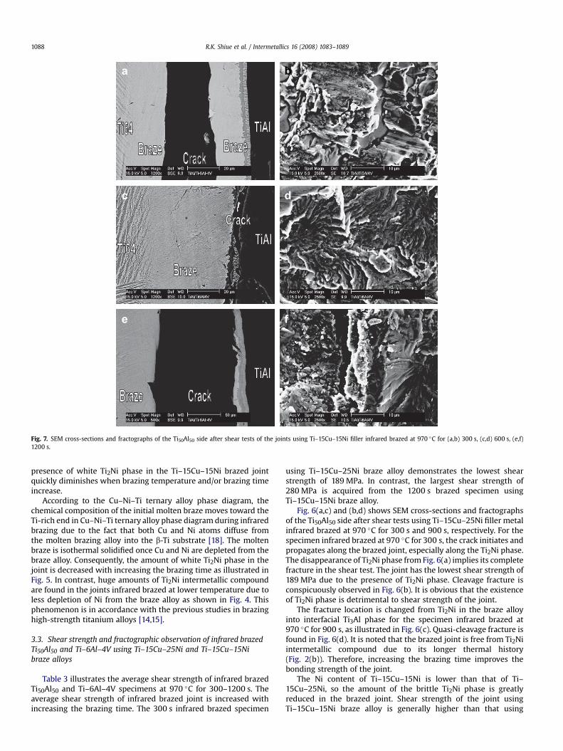
Fig. 7. SEM cross-sections and fractographs of the Ti50Al50 side after shear tests of the joints using Ti–15Cu–15Ni filler infrared brazed at 970 �C for (a,b) 300 s, (c,d) 600 s, (e,f)1200 s.
R.K. Shiue et al. / Intermetallics 16 (2008) 1083–10891088
presence of white Ti2Ni phase in the Ti–15Cu–15Ni brazed jointquickly diminishes when brazing temperature and/or brazing timeincrease.
According to the Cu–Ni–Ti ternary alloy phase diagram, thechemical composition of the initial molten braze moves toward theTi-rich end in Cu–Ni–Ti ternary alloy phase diagram during infraredbrazing due to the fact that both Cu and Ni atoms diffuse fromthe molten brazing alloy into the b-Ti substrate [18]. The moltenbraze is isothermal solidified once Cu and Ni are depleted from thebraze alloy. Consequently, the amount of white Ti2Ni phase in thejoint is decreased with increasing the brazing time as illustrated inFig. 5. In contrast, huge amounts of Ti2Ni intermetallic compoundare found in the joints infrared brazed at lower temperature due toless depletion of Ni from the braze alloy as shown in Fig. 4. Thisphenomenon is in accordance with the previous studies in brazinghigh-strength titanium alloys [14,15].
3.3. Shear strength and fractographic observation of infrared brazedTi50Al50 and Ti–6Al–4V using Ti–15Cu–25Ni and Ti–15Cu–15Nibraze alloys
Table 3 illustrates the average shear strength of infrared brazedTi50Al50 and Ti–6Al–4V specimens at 970 �C for 300–1200 s. Theaverage shear strength of infrared brazed joint is increased withincreasing the brazing time. The 300 s infrared brazed specimen
using Ti–15Cu–25Ni braze alloy demonstrates the lowest shearstrength of 189 MPa. In contrast, the largest shear strength of280 MPa is acquired from the 1200 s brazed specimen usingTi–15Cu–15Ni braze alloy.
Fig. 6(a,c) and (b,d) shows SEM cross-sections and fractographsof the Ti50Al50 side after shear tests using Ti–15Cu–25Ni filler metalinfrared brazed at 970 �C for 300 s and 900 s, respectively. For thespecimen infrared brazed at 970 �C for 300 s, the crack initiates andpropagates along the brazed joint, especially along the Ti2Ni phase.The disappearance of Ti2Ni phase from Fig. 6(a) implies its completefracture in the shear test. The joint has the lowest shear strength of189 MPa due to the presence of Ti2Ni phase. Cleavage fracture isconspicuously observed in Fig. 6(b). It is obvious that the existenceof Ti2Ni phase is detrimental to shear strength of the joint.
The fracture location is changed from Ti2Ni in the braze alloyinto interfacial Ti3Al phase for the specimen infrared brazed at970 �C for 900 s, as illustrated in Fig. 6(c). Quasi-cleavage fracture isfound in Fig. 6(d). It is noted that the brazed joint is free from Ti2Niintermetallic compound due to its longer thermal history(Fig. 2(b)). Therefore, increasing the brazing time improves thebonding strength of the joint.
The Ni content of Ti–15Cu–15Ni is lower than that of Ti–15Cu–25Ni, so the amount of the brittle Ti2Ni phase is greatlyreduced in the brazed joint. Shear strength of the joint usingTi–15Cu–15Ni braze alloy is generally higher than that using
R.K. Shiue et al. / Intermetallics 16 (2008) 1083–1089 1089
Ti–15Cu–25Ni filler. Increasing the Ni content of the braze alloyresults in more Ti2Ni phase formed in the joint, so lower shearstrength of the joint is obtained from the test. Fig. 7(a,c,e) and (b,d,f)displays SEM cross-sections and fractographs of the Ti50Al50 sideafter shear tests using Ti–15Cu–15Ni alloy infrared brazed at 970 �Cfor 300 s, 600 s and 1200 s, respectively. For the Ti–15Cu–15Nialloy, shear strength of the joint infrared brazed at 970 �C for 300 sdisplays lower shear strength of 240 MPa, and the joint is fracturedalong Ti2Ni phase, as illustrated in Fig. 7(a). For specimens infraredbrazed at 970 �C above 600 s, there is no blocky Ti2Ni phase inthe joint any more. Cracks are initiated from the interfacial Ti3Alphase, as shown in Fig. 7(c) and (e), and they demonstrate almostthe similar bonding strength in the shear test. Because all fracto-graphs displayed in Fig. 7 are cleavage dominated fracture, bothTi2Ni and interfacial Ti3Al phases are of inherent brittleness.
According to shear test results, the bonding strength of the jointcan be improved by using higher brazing temperature, longerbrazing time and by employing the filler metal with lower Nicontent, say Ti–15Cu–15Ni, in order to avoid or reduce the forma-tion of Ti2Ni phase in the brazed joint. However, the stableinterfacial Ti3Al limits the bonding strength between Ti50Al50 andTi–6Al–4V even for the brazed joint without blocky Ti2Ni phase.Unfortunately, at present study, the interfacial Ti3Al layer cannot beremoved from the joint by changing the infrared brazingconditions.
4. Conclusions
Microstructural evolution and bonding strength of the infraredbrazed Ti50Al50 and Ti–6Al–4V joint using Ti–15Cu–25Ni and Ti–15Cu–15Ni braze alloys have been evaluated in the study. Primaryconclusions are summarized in the following:
1. The joint mainly consists of Ti-rich, Ti2Ni and interfacial Ti3Alphases. The amount of Ti2Ni decreases with increasing thebrazing temperature and/or time due to the diffusion of Niatoms from the braze alloy into the Ti–6Al–4V substrate. Incontrast, the thickness of the interfacial Ti3Al phase is in-sensitive to infrared brazing conditions. The interfacial Ti3Al isprimarily resulted from the cooling cycle of brazing due tolimited solubilities of Al in a-Ti.
2. The average shear strength of infrared brazed joint increaseswith increasing the brazing time. The 300 s infrared brazedspecimen using Ti–15Cu–25Ni braze alloy demonstrates thelowest shear strength of 189 MPa. In contrast, the highest shearstrength of 280 MPa is acquired from the 1200 s brazed spec-imen using Ti–15Cu–15Ni braze alloy.
3. The presence of both Ti2Ni and interfacial Ti3Al phasesdeteriorates shear strength of the joint. The bonding strengthof joint can be improved by using higher brazing temperature,
longer brazing time and by employing the filler metal withlower Ni content, say Ti–15Cu–15Ni, so to avoid or reduce theformation of Ti2Ni in the brazed joint. However, the stable in-terfacial Ti3Al layer in between Ti–6Al–4V and Ti50Al50 confinesthe bonding strength even for the brazed joint without thebrittle Ti2Ni phase. In the present study, this layer cannot beremoved from the joint by changing infrared brazingconditions.
Acknowledgements
The authors gratefully acknowledge the financial support of thisresearch by the National Science Council (NSC), Taiwan, Republic ofChina, under the Grant number NSC 95-2221-E002-081-MY2.
References
[1] Liu CT. Recent advances in ordered intermetallics. Mater Chem Phys 1995;42:77–86.
[2] Tetsui T, Ono S. Endurance and composition and microstructure effectson endurance of TiAl used in turbochargers. Intermetallics 1999;7:689–97.
[3] Liu CT, Maziasz PJ. Microstructural control and mechanical properties of dual-phase TiAl alloys. Intermetallics 1998;6:653–61.
[4] Liu CT, Schneibel JH, Maziasz PJ, Wright JL, Easton DS. Tensile properties andfracture toughness of TiAl alloys with controlled microstructures.Intermetallics 1996;4:429–40.
[5] Roger R, Collings EW, Welsch G. Materials properties handbook: titaniumalloys. Materials Park: ASM International; 1993.
[6] Olson DL, Siewert TA, Liu S, Edwards GR. ASM handbook. In: Welding,soldering and brazing, vol. 6. Materials Park: ASM International; 1993.
[7] Humpston G, Jacobson DM. Principles of soldering and brazing. MaterialsPark: ASM International; 1993.
[8] Schwartz M. Brazing: for the engineering technologist. New York: Chapman &Hall; 1995.
[9] Shiue RK, Wu SK, Chan CH. Infrared brazing Cu and Ti using a 95Ag–5Al brazealloy. Metall Mater Trans 2004;35A(10):3177–86.
[10] Shiue RK, Wu SK, Chen SY. Infrared brazing of TiAl intermetallic using BAg-8braze alloy. Acta Mater 2003;51(7):1991–2004.
[11] Liu CC, Ou CL, Shiue RK. The microstructural observation and wettability studyof brazing Ti–6Al–4V and 304 stainless steel using three braze alloys. J MaterSci 2002;37(11):2225–35.
[12] Tetsui T. Effects of brazing filler on properties of brazed joints between TiAland metallic materials. Intermetallics 2001;9:253–60.
[13] Wallisa IC, Ubhia HS, Bacosb MP, Jossob P, Lindqvistc J, Lundstromc D, et al.Brazed joints in g TiAl sheet: microstructure and properties. Intermetallics2004;12:303–16.
[14] Chang CT, Du YC, Shiue RK, Chang CS. Infrared brazing of high-strength tita-nium alloys by Ti–15Cu–15Ni and Ti–15Cu–25Ni filler foils. Mater Sci Eng A2006;420:155–64.
[15] Chang CT, Shiue RK, Chang CS. Microstructural evolution of infrared brazedTi-15-3 alloy using Ti–15Cu–15Ni and Ti–15Cu–25Ni fillers. Scr Mater 2006;54(5):853–8.
[16] Massalski TB. Binary alloy phase diagrams. Materials Park: ASM International;1990.
[17] Yang YS, Wu SK. A study by high-resolution electron microscopy of an a2þ gtwo-phase Ti-40 at.% Al alloy. Philos Mag 1993;67:463–78.
[18] Villars P, Prince A, Okamoto H. Handbook of ternary alloy phase diagrams.Materials Park: ASM International; 1995.