Embed Size (px)
Citation preview

Introduction to GPS and other Global Navigation Satellite Systems
Michael C. Moreau, Ph.D. Presented by: Luke Winternitz, Ph.D. NASA Goddard Space Flight Center 37th Annual Time and Frequency Metrology Seminar 7 June 2012
https://ntrs.nasa.gov/search.jsp?R=20120010317 2018-07-16T17:38:08+00:00Z

2
Outline n Introduction n The U.S. Global Positioning System
q History q Current Status q Modernization and New
Capabilities n Satellite Navigation System
Fundamentals: q Satellites & Signals q Solutions q Errors
n Other Global Navigation Satellite Systems and Augmentations: q GLONASS, GALILEO, BEIDOU (COMPASS), QZSS
3
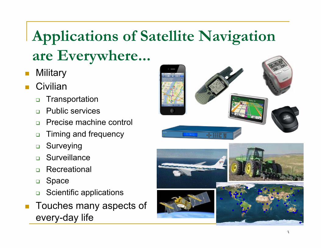
Applications of Satellite Navigation are Everywhere...
n Military n Civilian
q Transportation q Public services q Precise machine control q Timing and frequency q Surveying q Surveillance q Recreational q Space q Scientific applications
n Touches many aspects of every-day life

Satellite Navigation Systems Provide:
n Accuracy q three dimensional accuracies of a few meters, and
down to the level of millimeters for users with specialized equipment/processing
n Availability q signal available anywhere on Earth where the
user has a clear view of the sky n Integrity
q the assurance that the expected performance will be realized
4

5
(Approximate)GNSS Timeline

The U.S. Global Positioning System (GPS) - History, Status, and Future

7
GPS History
• Developed by the US Department of Defense q Early GPS program driver was Trident Missile Program
(Submarine launched ICBM) q Satellites carry a nuclear detonation detection payload
• Early Satellite Navigation Systems q TRANSIT q Timation (first atomic frequency standards flown in space) q USAF 621B Program (use of PRN codes for ranging)
• First prototype GPS satellite launched in 1978 • First Block II (Operational) GPS satellite launched
1989 • Full Operational Capability declared in 1994 • First in series of “modernized” GPS satellites began
launching in 2005
8
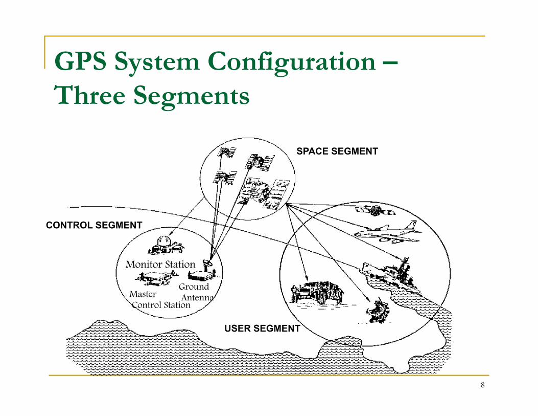
GPS System Configuration – Three Segments
SPACE SEGMENT
CONTROL SEGMENT
USER SEGMENT
Monitor Station
Master Control Station
Ground Antenna

9
n Nominal 24 satellite constellation q Semi-synchronous, circular orbits
(~20,200 km/10,900 nautical miles altitude)
q Repeating ground tracks (11 hours 58 minutes)
q Six orbital planes, inclined at 55 degrees, four vehicles per plane Ø Designed for global coverage (at least 4 sats in view)
n Redundant cesium and/or rubidium clocks on board each satellite
n There have been 1-3 replenishment launches per year in recent years
GPS Space Segment

Current GPS Constellation Status
• 31 space vehicles currently in operation • 10 GPS IIA • 12 GPS IIR • 7 GPS IIR-M • 2 IIF • 4 additional satellites in residual
status • 1 additional IIR-M waiting to be set
healthy • Next launch expected: Sept. 2012 • Continuously assessing constellation
health to determine launch need • Global GPS civil service performance
commitment met continuously since Dec 1993
Block II/IIA Built by Boeing Aerospace
Launched 1989 - 1997
Block IIR/IIR-M Built by Lockheed Martin
Launched 1997 - 2009
Block IIF Built by Boeing Aerospace
First Launch in 2010

11
SPACE VEHICLE Broadcasts the Signal in Space (SIS) PRN codes,
L-band carriers, and 50 Hz navigation message (stored in memory)
SPACE-TO-USER INTERFACE CONTROL-SPACE INTERFACE
MONITOR STATION n Sends raw
observations to MCS
MASTER CONTROL STATION n Checks for anomalies n Computes SIS portion of URE n Generates new orbit and clock
predictions n Builds new upload and sends to GA
GROUND ANTENNA n Sends new
upload to SV
GPS Control Segment

12
Control Segment – Map
n The current operational control segment includes a master control station, an alternate master control station, 12 command and control antennas, and 16 monitoring sites.
n Data from Air Force and NGA monitor stations incorporated into Control Segment Kalman filter solution.
13
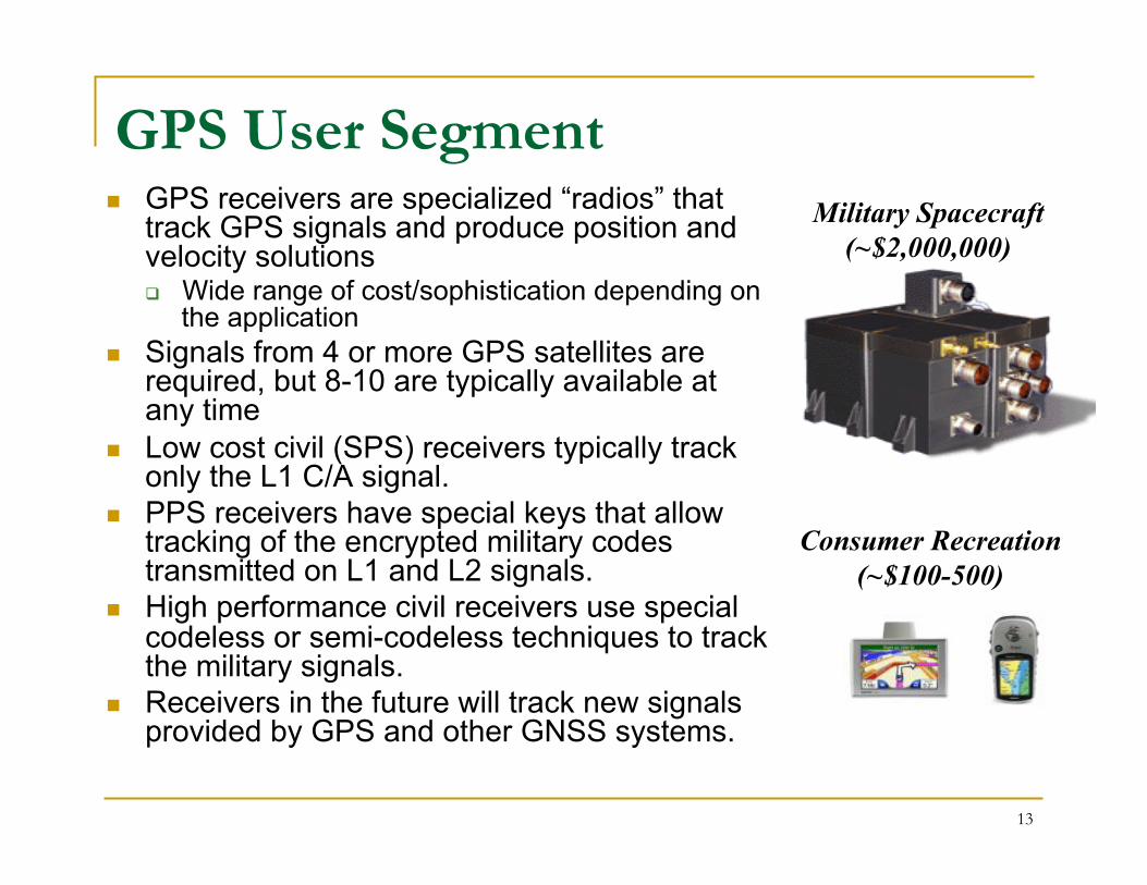
GPS User Segment n GPS receivers are specialized “radios” that
track GPS signals and produce position and velocity solutions q Wide range of cost/sophistication depending on
the application n Signals from 4 or more GPS satellites are
required, but 8-10 are typically available at any time
n Low cost civil (SPS) receivers typically track only the L1 C/A signal.
n PPS receivers have special keys that allow tracking of the encrypted military codes transmitted on L1 and L2 signals.
n High performance civil receivers use special codeless or semi-codeless techniques to track the military signals.
n Receivers in the future will track new signals provided by GPS and other GNSS systems.
Consumer Recreation (~$100-500)
Military Spacecraft (~$2,000,000)

14
n Two L-band carrier frequencies L1 = 1575.42 MHz L2 = 1227.60 MHz
n Two PRN Codes – Uniquely Identify Each Satellite q C/A: Coarse Acquisition (Civilian) Code
n Broadcast only on L1 carrier n Available to all users n One millisecond repeat interval
q P(Y): Military Code n Y code is encrypted version of P code – code sequence not published n Available only to authorized (military) users on both L1 and L2 carriers n 267 day repeat interval, divided into week-long segments transmitted by
each satellite n PRN Codes are modulated with Navigation Message Data
q Provides ephemeris data and clock corrections for the GPS satellites
q Low data rate (50 bps)
Legacy GPS Signal Structure

15
n System-wide improvements in: q Accuracy q Availability q Integrity q Reliability
n Robustness against interference n Improved indoor, mobile, and urban use n Interoperability with other GNSS constellations n Backward compatibility
GPS Modernization - Goals

16
Second civil signal • Designed to meet commercial needs
• Higher accuracy through ionospheric correction
• 1st launch: Sep 2005 (GPS IIR-M); 24 satellites: ~2016
Third civil signal
• Designed to meet demanding requirements for transportation safety-of-life
• 1st launch: May 2010 (GPS IIF); 24 satellites: ~2019
Fourth civil signal
• Designed with international partners for GNSS interoperability
• More robust across broad range of applications
• Begins with GPS III
• 1st launch: ~2014 (GPS III); 24 satellites: ~2021
GPS Modernization - New Civil Signals
Benefits existing professional receivers
Under trees Urban Canyons
L2C
L5
L1C
Courtesy Thomas D. Powell, GPS Systems Engineering, The Aerospace Corporation, 18 April 2010
17
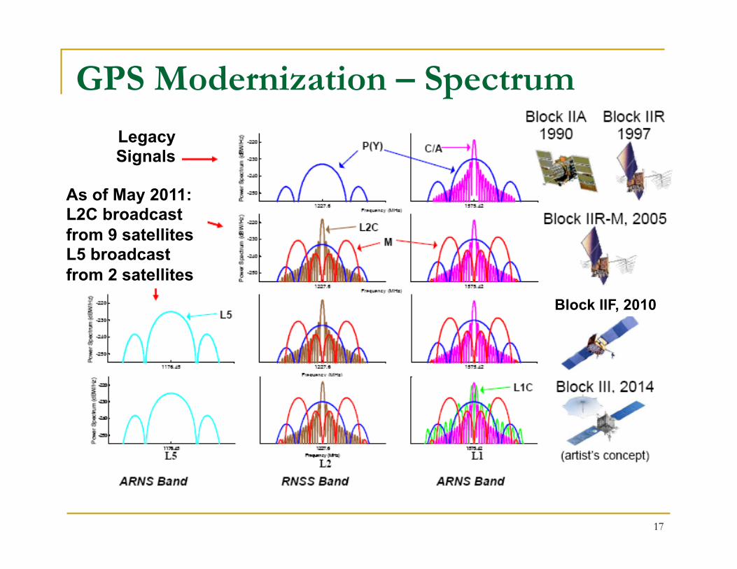
GPS Modernization – Spectrum
As of May 2011: L2C broadcast from 9 satellites L5 broadcast from 2 satellites
Legacy Signals
Block IIF, 2010

Spectrum of Other GNSS Systems
1560 1570 1580 1590 1600 16101170 1180 1190 1200 1210 1220 1230 1240 1250 1260 1270 1280 1290 1300 Frequency (MHz)
Color code: Blue—open signals, Red—restricted or encrypted signals L1
L5 L2 GPS
Current GLONASS
SBAS
Galileo
QZSS
IRNSS
Proposed COMPASS
Proposed GLONASS

19
• Architecture Evolution Plan (AEP) • Transitioned in 2007 • Modern distributed system replaced 1970’s mainframes • Increased capacity for monitoring of GPS signals to 100%
worldwide coverage (was 96.4%) and have 99.8% of world double covered
• Increased worldwide commanding capability from 92.7% to 94.5% while providing nearly double the backup capability
• Next Generation Operational Control Segment (OCX) • Enables modernized messaging • Controls more capable GPS constellation • $1.53B contract awarded February 2010 • Deployed in 2015 timeframe
GPS Modernization – Ground
Courtesy Thomas D. Powell, GPS Systems Engineering, The Aerospace Corporation, 18 April 2010

20
GPS Modernization Summary
GPS IIR-M
2005
• IIA/IIR capabilities plus: o 2nd civil signal
(L2C) o M-Code (L1M &
L2M)
GPS IIA/GPS IIR
1995
• Standard Positioning Service (SPS) o Single frequency
(L1) coarse acquisition code navigation
• Precise Positioning Service (PPS) o Y-Code (L1 P(Y) &
L2 P(Y))
GPS IIF
2010
• IIR-M capability plus o 3rd civil signal
(L5) o 12 year design
life
GPS III
2014 - 2025
• Backward compatible • 4th civil signal (L1C) • Increased accuracy • Increased integrity • Increased design life
Ground Control Segment
Architecture Evolution Plan
(AEP)
Next Generation Control Segment
(OCX)
Legacy Control System
Space Segment
Courtesy Thomas D. Powell, GPS Systems Engineering, The Aerospace Corporation, 18 April 2010

21
Performance Standards • The AF, DoD, and U.S. Government are committed to being good
stewards of GPS • The GPS Standard Positioning Service (SPS) Performance Standard
defines the levels of performance the U.S. Government commits to provide civil GPS users – Precise Positioning Service (PPS) Performance Standard for military
• Documents updated periodically to reflect service improvements • GPS SPS Performance Standard (Sep 2008) available on gps.gov
website – http://www.gps.gov/technical/ps/
Courtesy Thomas D. Powell, GPS Systems Engineering, The Aerospace Corporation, 18 April 2010

22
4.6 4.3
3.0 2.7
1.8 1.5
1.1 1.0 0.8
0
1
2
3
4
5
6
7
1990 1992 1994 1996 1997 2001 2004 2006 2009
RM
S SI
S U
RE
(m)
PPS Signal in Space Performance R
MS
Sign
al-in
-Spa
ce U
ser R
ange
Err
or (U
RE)
, m
eter
s
2008 PPS Performance Standard (Worst of any PPS SIS URE)
Signal-in-Space User Range Error is the difference
between a GPS satellite’s navigation data (position and
clock) and the truth, projected on the line-of-sight
to the user
System accuracy exceeds published standard
2008
0.9
Decreasing range error
Courtesy Thomas D. Powell, GPS Systems Engineering, The Aerospace Corporation, 18 April 2010

23
N/A
1.6 1.2 1.1
0.9
0
1
2
3
4
5
6
7
RM
S SI
S U
RE
(m)
SPS Signal in Space Performance R
MS
Sign
al-in
-Spa
ce U
ser R
ange
Err
or (U
RE)
, m
eter
s
2008 SPS Performance Standard (Worst of any SPS SIS URE)
2001 SPS Performance Standard (RMS over all SPS SIS URE)
N/A N/A N/A N/A
Selective Availability (SA)
System accuracy exceeds published standard
Signal-in-Space User Range Error is the difference
between a GPS satellite’s navigation data (position and
clock) and the truth, projected on the line-of-sight
to the user
1990 1992 1994 1996 1997 2001 2004 2006 2009 2008
Decreasing range error 1.0
Courtesy Thomas D. Powell, GPS Systems Engineering, The Aerospace Corporation, 18 April 2010

Satellite Navigation System Fundamentals

25
n Precise timing is fundamental to realizing high performance from satellite navigation systems
n A typical GPS receiver provides user position estimates accurate to a few meters by measuring the range (signal delay) between the user and multiple GPS satellites q Assume the specified ranging error contribution from the satellite
clock is one meter q One-meter ranging error is equivalent to 3.3 ns
(one meter / speed of light = 3.3x10⁻⁹ s)
n GPS control segment predicts GPS clock performance over a 12 hour period (nominal frequency at which clock data is uploaded to the GPS satellites) q 3.3 ns of 12 hours requires a clock with about one part in 1013
stability: 3.3x10⁻⁹ s / 43200 s = 0.8x10⁻¹³
Importance of Precise Timing to GPS

26
Atomic Clocks in Space n GPS satellites carry redundant rubidium or cesium
oscillators (or a combination) q Precise frequency standard provides a reference for
generating the ranging signals transmitted by the satellites n Clocks on the satellites are steered by GPS ground
controllers to Coordinated Universal Time (UTC) as maintained by the US Naval Observatory (USNO) q A direct reference to UTC(USNO) can be made
automatically by most timing receivers by using corrections included in the broadcast GPS NAV message.
q By mutual agreement, UTC(USNO) and UTC(NIST) are maintained within 100ns (and frequency offset <1x10-13)
n Traceability to UTC(USNO) enables precise time and frequency transfer on a global scale.

27
n Atomic clocks in GPS satellites are given a fixed fractional frequency offset of -4.46475x10⁻¹⁰ to compensate for relativistic effects in the GPS satellite orbits q Second-order Doppler shift – a clock moving in an inertial
frame runs slower than a clock at rest q Gravitational frequency shift – a clock at rest in a lower
gravitational potential runs slower than a clock at rest in a higher gravitational potential
n Without this offset, GPS satellite clocks would gain ~38 microseconds per day relative to clocks on the ground (~11 km range error)
n GPS receivers apply an additional correction of up to 23 ns (~7 meters) to account for eccentricity in the satellites’ orbit
Modeling of Relativistic Effects in GPS

28
Satellite Navigation and Precise Timing are Fundamentally Linked
n GPS has become a primary system for distributing time and frequency globally
n Satellite navigation systems allow users to synchronize clocks and calibrate and control oscillators in any location with access to an antenna
n Applications range from use in tele-communications networks to timing laboratories

29
Precise Timing is the Basis for the Navigation Solution
n Satellite navigation is based on: q The precise measurement of time q The constancy of the speed of light
n GPS and other systems use the concept of trilateration: q Satellite (transmitter) positions are known q Receiver position is unknown
n Receiver position is estimated using measurements of the transit-time of a signal between the satellite and receiver

30
T1
ρ1
T2
ρ2
T3 ρ3
Trilateration Example: 3 Transmitters, 1 Receiver
n Measurement of range requires precise knowledge of the time the signal is transmitted from the satellite, and received at the receiver
n Range (ρ) or “time of flight” measurement performed using ranging code on the signal
Receiver Location

31
n The position solution involves an equation with four unknowns: q Three components of receiver position (x, y, z) q Receiver clock bias
Ø Position accuracy of ~1 m implies knowledge of the receiver clock to within ~3 ns
n Requires simultaneous measurements from four satellites q The receiver makes a range measurement to the
satellite by measuring the signal propagation delay q Data message modulated on the ranging signal
provides: n precise location of the satellite n corrections for errors in the satellite clock
Position Solution

32
GPS is a Spread-Spectrum Communications System
n Uses Code Division Multiple Access (CDMA): q Each satellite assigned a unique Pseudo-Random Noise (PRN)
Code q All satellites transmit at the same frequency
n The power associated with the transmitted data is “spread” over a wide frequency band
n The received power is very low (below ambient noise levels)
n The transmitted signal is the combination of three signals: q L-band carrier signal q PRN code q 50 Hz data message
])(cos[)()()( 1 θω +⋅⋅⋅= ttctdAty L
33
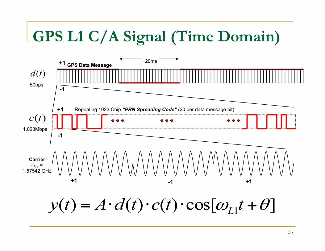
GPS L1 C/A Signal (Time Domain)
]cos[)()()( 1 θω +⋅⋅⋅= ttctdAty L
1.023Mbps
)(td
Carrier ωL1 =
1.57542 GHz
50bps
)(tcRepeating 1023 Chip “PRN Spreading Code” (20 per data message bit)
GPS Data Message 20ms +1
-1
+1
-1
+1 -1 +1

34
GPS L1 C/A Signal (Frequency Domain)
frequency
frequency
1. Data Message Spectrum
2. Data*PRN Code Spectrum Signal is “Spread”
3. Data*Code*Carrier Spectrum
This is the transmitted signal
0 Hz
0 Hz
0 Hz 1.57542 GHz
50 Hz
1.023 MHz
1.023 MHz

35
n To detect the GPS signal and recover the navigation data, the receiver must produce a replica of the GPS signal with the correct time delay and Doppler to mix with the incoming signal q PRN codes for satellites are known q Receiver performs a search across possible time
delays and Doppler shifts to acquire the signal n GPS measurements are derived from the values of the
PRN code phase (time delay) and carrier Doppler shift necessary to produce a large correlation with the incoming signal q Measurements are products of the receiver signal
tracking loops
GPS Receiver Acquisition and Tracking

36
GPS Observables n GPS receivers typically report the following
measurements q Pseudorange
n Propagation delay measured using the transmitted PRN code
q Doppler n Measured frequency shift of the received carrier signal
q Carrier Phase n Measured by counting accumulated cycles of the carrier
signal
q C/N0 n Carrier to noise spectral density (dB-Hz)

37
Pseudorange
Δt
GPS transmitted C/A-code
Receiver replicated C/A-code
Finding Δt for each GPS signal tracked is called “code correlation”
n Δt is proportional to the GPS-to-receiver range n Four pseudorange measurements can be used
to solve for receiver position

38
Measurement Equation
( )Trk ttc −=ρ
n GPS receiver measures range or distance to the GPS satellite by measuring the transit time of the signal:
time of transmission, encoded in signal by GPS satellite clock
(known precisely)
time of signal reception, (based on receiver clock,
can be significantly in error)
n Measurement is called “pseudorange” because the measurement includes the transit time biased by the error in the receiver clock

39
n The GPS pseudorange measurement reaching the receiver, yR has several changes:
n Time-delay, τ n Doppler frequency shift, ωd
n Phase shift, δθ n Amplitude of received signal, Ar
n Wideband noise, n
GPS Pseudorange Measurement Equation
( )( ) ( )[ ] nttctdAty dLRR +++−+⋅−⋅−⋅= δθθτωωττ 1cos)()()(
40
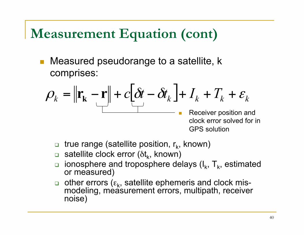
Measurement Equation (cont)
q true range (satellite position, rk, known) q satellite clock error (δtk, known) q ionosphere and troposphere delays (Ik, Tk, estimated
or measured) q other errors (εk, satellite ephemeris and clock mis-
modeling, measurement errors, multipath, receiver noise)
[ ] kkkkk TIttc εδδρ +++−+−= rrk
n Measured pseudorange to a satellite, k comprises:
n Receiver position and clock error solved for in GPS solution

41
λ
The Doppler-shifted GPS carrier signal is mixed with the receiver reference signal to produce a beat wave whose phase can be measured with mm-level precision
N = unknown integer number of cycles f = measured fractional cycles
one L1 wavelength ≈ 19 cm
Carrier Phase
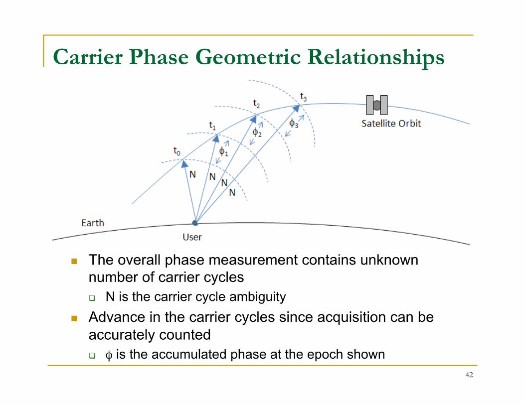
Carrier Phase Geometric Relationships
42
n The overall phase measurement contains unknown number of carrier cycles q N is the carrier cycle ambiguity
n Advance in the carrier cycles since acquisition can be accurately counted q φ is the accumulated phase at the epoch shown

43
n Two primary factors affect the fundamental position and time accuracy possible from the system: q Ranging error – a function of the quality of the broadcast
signal and data q Geometry – the distribution of satellites in the sky
n The actual positioning accuracy achieved depends on system performance plus many other factors: q The design of the receiver (receiver/antenna noise levels,
modeling errors, etc.) q Environmental effects such as ionosphere and troposphere
signal delays, field of view obstructions, multipath signals, and jamming/interference.
Solution Accuracy

44
n User Range Error q Signal-In-Space User Range Error (URE)
is the difference between a GPS satellite’s navigation data (position and clock) and the truth, projected on the line-of-sight to the user.
q Indication of signal quality for an individual satellite
n Composite of several factors q stability of particular satellite’s clock q predictability of the satellite’s orbit
Ranging Error
URE

45
n Geometric Dilution of Precision (GDOP) is a measure of the quality of the receiver-to-GPS satellite range geometry q Related DOPs exist for position, horizontal, vertical, and time
dilutions of precision n Used in conjunction with the URE to forecast navigation
and timing performance, weight measurements n For GPS, DOP can range from 1 to infinity, with values
in the 2-3 range being typical for GPS
Geometry – Dilution of Precision
Good (Low) GDOP Poor (High) GDOP

46
Typical Error Budget (Based on GPS)
Error Source Typical Error
Ionosphere (< 1000 km) 1-5 m (single frequency, using broadcast model)
Troposphere (< 20 km) 0.1-1 m
GPS orbits 2.0 m (RMS)
GPS clocks 2.0 m (RMS)
Multipath (“clean” environment)
0.5-1 m code 0.5-1 cm carrier
Receiver Noise 0.25-0.5 m (RMS) code 1-2 mm (RMS) carrier

47
Differential Techniques
n Receivers in close proximity can have their common error sources cancel q Ionosphere and troposphere delays q Satellite orbit error q Satellite clock error
n Single Differences (SD) – formed from like measurements of the same GPS satellite made from two receivers q Removes errors common to both receivers
n Double Differences (DD) – formed by differencing two SD measurements from the same satellite
n Fixed Base Station q Broadcast corrections from a base station
at a known location
base

Other GNSS Systems and Augmentations

GPS US
(24+)
Galileo EU (27)
GLONASS Russia
(24)
Global GNSS Constellations Beidou/Compass
China (35)

50
GLONASS: GLObal NAvigation Satellite System
n Radio-based satellite navigation system operated by the Russian Space Forces
n 24 satellites in 3 orbital planes n Each satellite transmits signal on
unique frequency (FDMA) n First satellite launched in 1982 n System fell into disrepair with
collapse of Soviet Union n Replenishment and modernization
of the constellation made a top priority under the Putin Presidency
n Constellation Status: n http://www.glonass-ianc.rsa.ru/en/ GLONASS Satellite Constellation

51
GLONASS Status n GLONASS Constellation Status (11 May 2012)
n 31 Total satellites in constellation n 24 Operational n - In Commissioning Phase n 2 In Maintenance n 4 On-orbit spares
n Most recent launch in Nov 2011: q Nominal constellation of 24 operational satellites re-
established in 2011 n GLONASS accuracy has improved significantly
over the past five years; approaching performance of GPS

52
GLONASS Modernization n GLONASS modernization efforts include:
q Introduction of new CDMA signals for improved interoperability with other GNSS systems
q Continue to broadcast legacy FDMA signals q New GLONASS K satellites with improved accuracy and longer
design life q Improvements to ground control system
For more information, see: GLONASS Status and Progress, Sergey Revnivykh, 19 September 2011 http://www.navcen.uscg.gov/pdf/cgsicMeetings/51/3_GLONASS_CGSIC_Oleynik.pdf

53
n Galileo is a joint initiative of the European Commission (EC) and the European Space Agency (ESA).
n It will be interoperable with GPS and GLONASS, the two other global satellite navigation systems.
n Consists of 30 medium Earth orbit satellites, associated ground infrastructure, and regional/local augmentations.
n Will offer a basic service for free (Open Service), but will charge user fees for premium services.
GALILEO
http://www.esa.int/esaNA/galileo.html

54
Galileo Constellation Configuration
altitude ~23616 kmSMA 29993.707 km
inclination 56 degrees
• period 14 hours 4 min• ground track repeat about 10 days
GG AL IL E OAL IL E O DATADATA
27 + 3 satellites in three Medium Earth Orbits (MEO)
Walker 27/3/1Constellation

Galileo Implementation Plan
Galileo System Testbed v1!Validation of critical algorithms"
Galileo System Testbed v2!2 initial test satellites"
In-Orbit Validation!"4 IOV satellites plus
ground segment"
Full Operational Capability! 27 (+3) Galileo satellites"
2003
2005
2011
>2014
From “European GNSS Programmes EGNOS and Galileo,” Paul Verhoef
56
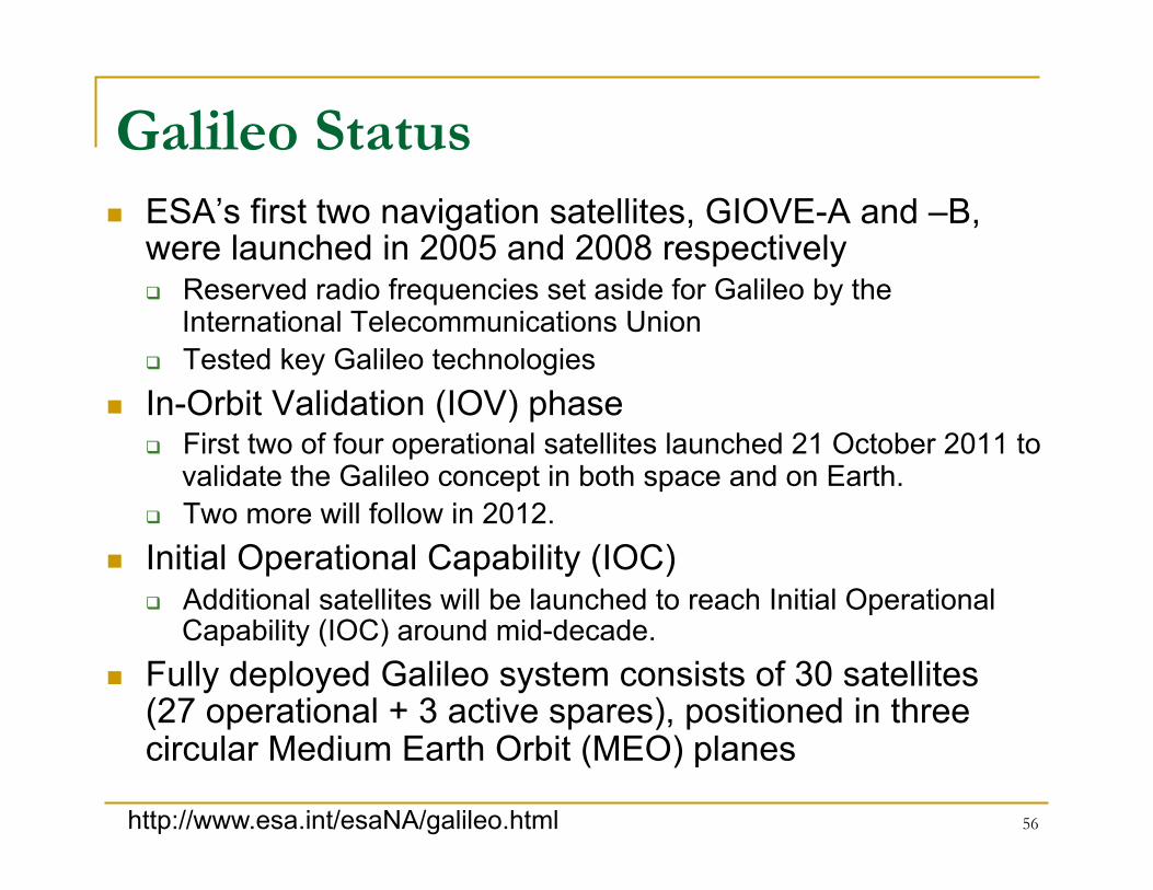
Galileo Status n ESA’s first two navigation satellites, GIOVE-A and –B,
were launched in 2005 and 2008 respectively q Reserved radio frequencies set aside for Galileo by the
International Telecommunications Union q Tested key Galileo technologies
n In-Orbit Validation (IOV) phase q First two of four operational satellites launched 21 October 2011 to
validate the Galileo concept in both space and on Earth. q Two more will follow in 2012.
n Initial Operational Capability (IOC) q Additional satellites will be launched to reach Initial Operational
Capability (IOC) around mid-decade. n Fully deployed Galileo system consists of 30 satellites
(27 operational + 3 active spares), positioned in three circular Medium Earth Orbit (MEO) planes
http://www.esa.int/esaNA/galileo.html

57
Chinese Compass System n In 2006 China announced plans to develop a 35-satellite,
global navigation system n The Compass system (also known as BeiDou) will
include 5 geostationary orbit (GEO) satellites and 30 medium Earth orbit (MEO) satellites
n BeiDou will provide three carrier frequencies foreseen to be interoperable with other systems.
n Demonstration Phase – completed in 2003 with launch of 3 Geostationary satellites
n Second Phase (BeiDou-2) – provision of satellite navigation services for Asia-Pacific region q As of April 2011, eight BeiDou-2 satellites launched (latest 4/10/11) q More than ten satellites planned by 2012 q System complete by 2020
http://www.beidou.gov.cn/

Regional Satellite Navigation Systems
q Indian Regional Navigational Satellite System (IRNSS) q Autonomous regional satellite navigation system
consisting of 7 satellites and ground segment q Developed by Indian Space Research Organization
q Quasi-Zenith Satellite System (QZSS) – Japan q Will provide an augmentation service which, when
used in conjunction with GPS, GLONASS or Galileo, will provide enhanced navigation in the Far East
q Consists of three satellites in highly elliptical orbits - satellites dwell at high elevations in the sky allowing enhanced coverage in urban canyons.
58

59
Satellite-Based Augmentation Systems (SBAS) n Wide Area Augmentation System (WAAS)
q Commissioned in 2003 and operated by the U.S. Federal Aviation Administration (FAA), to enable aircraft navigation in the U.S. National Airspace System (NAS)
n European Geostationary Navigation Overlay System (EGNOS) q Three geostationary satellites and a network of ground stations q Augments the US GPS satellite navigation system in Europe
n Japan's Multifunction-Transport-Satellite Satellite Augmentation System (MSAS) q MSAS for aviation use was commissioned in 2007
n India's GPS and Geo-Augmented Navigation System (GAGAN) (operational in 2011)
n Russian System of Differential Corrections and Monitoring (SDCM) (operational in 2011)

60
Other GPS Augmentations n Nationwide Differential GPS System (NDGPS):
q Ground-based augmentation system of ~80 sites operated by the U.S. Coast Guard, Federal Railroad Administration, and Federal Highway Administration, to provide increased accuracy and integrity to U.S. users on land and water.
n Local Area Augmentation System (LAAS): q Augmentation to GPS that focuses its service on the airport area
(approximately a 20-30 mile radius) q Broadcasts correction message via a very high frequency (VHF)
radio data link from a ground-based transmitter q LAAS is a US activity led by the FAA, but other nations are
developing their own ground based augmentation system projects
n NASA Global Differential GPS (GDGPS) System: q GDGPS is a commercial high accuracy (~ 10cm) GPS
augmentation system, developed by the Jet Propulsion Laboratory (JPL) to support real-time positioning, timing, and orbit determination requirements.

Radio Frequency Interference Concerns
n GPS Jamming: As the uses of satellite-positioning technology continue to grow, what can be done to stop deliberate and dangerous jamming of the signals? The Economist, Mar 10, 2011 q http://www.economist.com/node/18304246?
story_id=18304246http://www.economist.com/node/18304246?story_id=18304246
n Interference Studies Lead FCC to Block LightSquared Operations, April 2012 q http://www.gps.gov/news/2012/02/lightsquared/
61

62
Thank You.
Luke Winternitz, Ph.D. Components and Hardware Systems Branch
Code 596, NASA GSFC Greenbelt, MD 20771
Michael C. Moreau, Ph.D. Navigation and Mission Design Branch
Code 595, NASA GSFC Greenbelt, MD 20771

Backup Information and References
Subsequent charts provide additional information and references that could not be included in the presentation.

64
Acronyms and Definitions
AEP – GPS Architecture Evolution Program ARNS – Aeronautical Radio Navigation Service spectrum
band CDMA – Code Division Multiple Access C/A – GPS Course Acquisition Code C/N0 - Carrier to Noise Spectral Density COMPASS – Chinese Satellite Navigation System CORS – Continuously Operating Reference Stations DoD – Department of Defense EC – European Commission ESA – European Space Agency FDMA – Frequency Division Multiple Access Galileo – European Satellite Navigation System GDGPS – NASA Global Differential GPS System GDOP – Geometric Dilution of Precision GNSS – Global Navigation Satellite Systems GPS – US Global Positioning System GLONASS – Russian GLObal NAvigation Satellite System GST – Galileo System Time GTRF – Galileo Terrestrial Reference Frame IERS – International Earth Rotation Service IGS – International GNSS Service ITRS – International Terrestrial Reference System LAAS – Local Area Augmentation System
L1 – GPS signals at 1.57542 GHz L1C – New GPS code planned for L1 signal L2 – GPS signals at 1.22760 GHz L2C – New GPS code on L2 signal L5 – New GPS signals at 1.17645 GHz MEO – Medium Earth Orbit NASA – National Aeronautics and Space Administration NDGPS – Nationwide Differential GPS System NIMA – National Imagery and Mapping Agency, currently
known as National Geospatial-Intelligence Agency (NGA)
NIST – National Institutes of Standards and Technology OCS – GPS Operational Control Segment OCX – Next Generation GPS Operational Control Segment PRN – Pseudo-Random Noise PNT – Position, Navigation, and Timing P(Y) – GPS precision code QZSS – Japanese Quazi-Zenith Satellite System RMS – Root Mean Square RNSS - Radio Navigation Satellite Service spectrum band SBAS – Space Based Augmentation System TAI – International Atomic Time USAF – United States Air Force USNO – United States Naval Observatory URE – User Range Error UTC – Universal Coordinated Time WAAS – Wide Area Augmentation System

65
n Official U.S. Government information about the Global Positioning System (GPS) and related topics q http://gps.gov
n National Executive Committee for Space-Based Positioning, Navigation, and Timing (PNT) q http://pnt.gov/
n Federal Aviation Administration – Navigation Services q http://gps.faa.gov/index.htm
n US Coast Guard Navigation Center q http://www.navcen.uscg.gov/
n Civil GPS Service Interface Committee (CGSIC) Meetings q http://www.navcen.uscg.gov/?pageName=cgsicMeetings
n NASA Global Differential GPS System q http://www.gdgps.net/
GPS References

66
n Elliott D. Kaplan, Christopher J. Hegarty, Understanding GPS: Principles and Applications, Artech House Publishers, 2006.
n P. Misra, P. Enge, Global Positioning System: Signals, Measurements, and Performance, Ganga-Jamuna Press, 2001.
n B.W. Parkinson et al. (editors), Global Positioning System: Theory and Applications, Vol. 1&2, Progress in Astronautics and Aeronautics, 1997.
GPS References (continued)

67

68
2004 U.S. Space-Based Positioning, Navigation, and Timing Policy
n Recognizes the changing international scene q Other nations implementing space-based
systems that provide PNT services n National Space-Based PNT Executive
Committee q Chaired by Deputy Secretaries of Defense and
Transportation q Membership includes: State, Commerce,
Homeland Security, JCS and NASA n Established National Coordination Office
(NCO) with staff from each member agency
GNSS Compatibility and Interoperability Objectives
n Ensure compatibility - ability of U.S. and non-U.S. space-based PNT services to be used separately or together without interfering with each individual service or signal
n Achieve interoperability – ability of civil U.S. and non-U.S. space-based PNT services to be used together to provide the user better capabilities than would be achieved by relying solely on one service or signal
69

GLONASS

71
n 24 satellites in 3 orbital planes q ascending nodes 120 degrees apart q 8 satellites equally spaced in each plane q argument of latitude displacement of 45 degrees q planes have 15 degrees argument of latitude displacement
n Circular 19,100 km orbit q inclination angle of 64.8 degrees
n Complete one orbit in 11 h 15 min 44 s, minimum of 5 satellites are in view to users continuously, world-wide
n Cesium clocks on board satellites
GLONASS Constellation

72
GLONASS Signal Characteristics n Each satellite transmits signal on unique frequency (FDMA)
q Some satellites may use the same frequencies, but those satellites are placed in antipodal slots of orbit planes and they do not appear at the same time in a user’s view
n Two frequency bands q L1 = 1602 + n*0.5625 MHz q L2 = 1246 + n*0.4375 MHz q Where n is frequency channel number (n=0,1,2,…)
n Standard Precision (SP) Signal q PRN code clock rate 0.511 MHz q repeats each millisecond q civilian use
n High Precision (HP) Signal q PRN code clock rate 5.11 MHz q repeats each second q modulated by special code, includes anti-spoofing capability q military use

73
n Several Command Tracking Stations (CTS) throughout Russia
q St. Petersburg, Ternopol, Yeniseisk, Komsomolsk, Balkhash q track satellites in view and accumulate ranging data and telemetry
from the satellite signals q transmit updated information to satellites, as well as other control
information q ranging data is periodically calibrated using laser ranging devices
at Quantum Optical Tracking Stations within GCS. Each satellite specially carries laser reflectors for this purpose.
n System Control Center (SCC) in Krasnoznamensk (Moscow region) q process CTS site information to determine satellite clock and orbit
states and update the navigation message for each satellite.
GLONASS Control System

74
n GLONASS system time-scale q based on high-precision hydrogen clocks q relay signals to the phase control system (PCS) which
monitors satellite clock time/phase as transmitted by the navigation signals and determines satellite corrections for upload
q synchronized with UTC(SU) q also synchronized with UTC(CIS), which is maintained
by the All Union Institute for Physical, Technical, and Radio-Technical Measurements (VNIIFTRI) in Mendeleevo, near Moscow
q uses leap seconds n Ephemeris data in the Earth Parameter System 1990
(PZ-90), not GPS WGS-84
GLONASS Control System (cont)

Galileo

76
n Galileo is a joint initiative of the European Commission (EC) and the European Space Agency (ESA).
n It will be interoperable with GPS and GLONASS, the two operational global satellite navigation systems.
n Consists of 30 medium Earth orbit satellites, associated ground infrastructure, and regional/local augmentations.
n Will offer a basic service for free (Open Service), but will charge user fees for premium services.
GALILEO

77
Galileo Constellation Configuration
altitude ~23616 kmSMA 29993.707 km
inclination 56 degrees
• period 14 hours 4 min• ground track repeat about 10 days
GG AL IL E OAL IL E O DATADATA
27 + 3 satellites in three Medium Earth Orbits (MEO)
Walker 27/3/1Constellation

78
Position, Velocity and Time Services: n Open Service - providing positioning, navigation and timing services, free
of charge, for mass market navigation applications (future GPS SPS) n Commercial Service - provides added value over the Open Service
providing commercial revenue, such as dissemination of encrypted navigation related data (1 KBPS), ranging and timing for professional use - with service guarantees
n Safety of Life Service - Comparable with “Approach with Vertical Guidance” (APV-II) as defined in the ICAO Standards and Recommended practices (SARPs), and includes Integrity
n Public Regulated Service - for applications devoted to European/National security, regulated or critical applications and activities of strategic importance - Robust signal, under Member States control
Support to Search and Rescue n Search and Rescue Service coordinated with COSPAS SARSAT
The GALILEO Satellite Services

Galileo Navigation Signals and Frequencies
79 http://www.esa.int/esaNA/SEM86CSMD6E_galileo_1.html
Each Galileo Satellite will broadcast 10 navigation signals, making up the open (OS), safety-of-life (SOL), commercial (CS) and public regulated services (PRS)

Galileo Navigation Signals and Frequencies
80 http://www.esa.int/esaNA/SEM86CSMD6E_galileo_1.html
GPS L1 GPS L2 GPS L5
n Galileo open services realized by using the signals at L1, E5a and E5b.
n Various configurations of dual and single frequency navigation use are possible.
n L1 and E5a Galileo signals interoperability with GPS

81
Galileo System Design
n Galileo Terrestrial Reference Frame (GTRF): q An independent realization of the International Terrestrial
Reference System (ITRS) established by the Central Bureau of the International Earth Rotation Service (IERS).
q Differences between WGS84 and GTRF ~ a few cm. n Galileo System Time (GST):
q Shall be a continuous coordinate time scale steered towards the International Atomic Time (TAI) with an offset of less then 33 ns.
q Offset between GST and the GPS system time is monitored and broadcast to users, but may also be estimated in the receiver.
n Each Spacecraft will have 4 onboard clocks q 2 Rubidium Vapour q 2 Passive Hydrogen Maser

82
Agreement on GPS-Galileo Cooperation
n In 2004 the United States and the European Union established a partnership to ensure that GPS and Galileo will be interoperable at the user level for the benefit of civil users around the world. q Radio frequency compatibility and interoperability; q Trade and civil applications; q Design and development of the next generation of systems; and q Security issues related to GPS and Galileo.
n The agreement: q Ensures that Galileo's signals will not harm the navigation
warfare capabilities of the United States and the North Atlantic Treaty Organization military forces
q Calls for non-discrimination and open markets in terms of trade in civil satellite navigation-related goods and services
q Includes an agreement to establish a common civil signal at the L1 frequency
n Additional availability, precision, and robustness provided by complementary systems

83
n Further information can be found here: q http://www.esa.int/esaNA/index.html
GALILEO References
Quasi-Zenith Satellite System (QZSS)

n QZSS is a GPS augmentation system serving Japan and the Asia-Pacific region.
n Consists of three (3) satellites in highly-inclined, geostationary orbits so that one satellite always appears near the zenith above the region of Japan.
85 http://www.jaxa.jp/pr/brochure/pdf/04/sat12.pdf
Japanese Quasi-Zenith Satellite System (QZSS)

86
QZSS - Continued
n GPS Availability Enhancement q Improves availability of satellite positioning for areas such as
urban canyon and mountain terrain q The usage of the QZS at high elevation angles in combination
with GPS,
n GPS Performance Enhancement q Achieves high accuracy by transmitting position correction data q Achieves high reliability by sending integrity data
n Based on 2006 agreement between the U.S. and Japan, the navigation signals and messages of the QZSS offer complete interoperability with those of GPS
n First QZSS satellite (QZS-1) launched in Sept, 2010 q Utilization demonstration during 2011
http://qzss.jaxa.jp/is-qzss/index_e.html

QZSS Planned Signals
87 http://www.navcen.uscg.gov/pdf/cgsicMeetings/50/%5B2%5DJAPAN_REPORT_50TH_CGSIC10_9.pdf

Indian Regional Navigational Satellite System (IRNSS) n Autonomous regional satellite navigation system being
developed by Indian Space Research Organization . n The proposed system would consist of a constellation of
seven satellites and a support ground segment. q Three satellites in Geostationary orbits q Remaining satellites in highly elliptical orbits
n First launch targeted for 2011 n Completed and operational by 2014
88 http://www.oosa.unvienna.org/pdf/icg/2008/expert/2-3.pdf http://www.irnssindia.com/

Indian GPS Aided Geo Augmented Navigation (GAGAN)
n GAGAN is a Satellite Based Augmentation System (SBAS) over the Indian Air-space primarily meant for civil aviation
n Jointly implemented by the Indian Space Research Organization (ISRO) and the Airports Authority of India (AAI)
n Two signals: L1 and L5 n Technology Demonstration Phase completed in 2007 n Operational phase of GAGAN expected to be completed
by 2011
89 http://www.oosa.unvienna.org/pdf/icg/2008/expert/2-3.pdf

EGNOS
n The European Geostationary Navigation Overlay Service (EGNOS) augments the US GPS satellite navigation system and makes it suitable for safety critical applications such as flying aircraft or navigating ships through narrow channels.
EGNOSService Area!
EGNOS Satellite!Footprints!
http://www.esa.int/esaNA/GGG63950NDC_egnos_0.html

EGNOS Continued
n Consists of three geostationary satellites and a network of ground stations
n EGNOS is a joint project of ESA, the European Commission and Eurocontrol, the European Organisation for the Safety of Air Navigation.
n The EGNOS Open Service has been available since 1 October 2009.
n EGNOS positioning data are freely available in Europe through satellite signals to anyone equipped with an EGNOS-enabled GPS receiver.

MTSAT Space-based Augmentation System (MSAS) n Japanese SBAS (Satellite Based Augmentation System) n Supports differential GPS (DGPS) designed to
supplement the GPS system by reporting (then improving) on the reliability and accuracy of those signals
n MSAS for aviation use was commissioned on September 27, 2007
92

System of Differential Corrections and Monitoring (SDCM) n SBAS counterpart to the WAAS and the EGNOS
covering the Russian Federation. n The SDCM would perform integrity monitoring of both
GPS and GLONASS satellites as well as provide differential corrections and a posteriori analyses of GLONASS system performance.
n Network of ground reference stations and geostationary satellites
n Will launch three geostationary satellites in the 2010-2013 timeframe, the first scheduled to be operational in 2011
93