Embed Size (px)
Citation preview
IRCAT CIi1CTJLA-TLS
TATIOi:AL ADVISGY CCiJTTEE FOP. AEiLOLAUTICB
No. 112
TI-E LATCOR 28" COiiE.OiAL AIRPLAE (FRTcH)
A T en-P ass ener High-7ing ivionopl ane
Vlashington Eai'oh, 1930
::;TIoNAL ADV ISOPY GOL.MITT2E FOR AEROIAUTICS.
T)rpA-m f 1 T1CTTT 'T(\ 110 .ttL'..l.t.i1i I J.iu..JtjC'.. .Lj. ji.t,,.
THE "LATCOEiE 28 COI.iMERCIAL AIRPLANE (FREcH)
A Ten-Passenger High-Wing ionop1ane.*
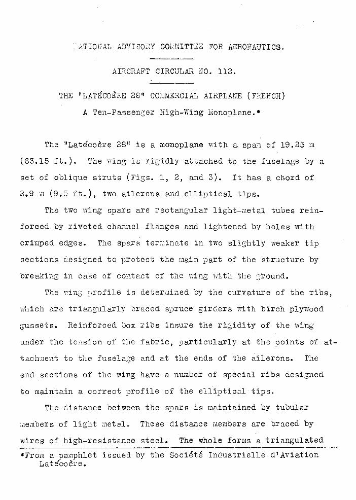
The "Late'coère 28" is a monoplane with a span of 19.25 m
(63.15 ft.). The wing is rigidly attached to the fuselage by a
set of oblique struts (Figs. 1, 2, and 3). It has a chord o±
2.9 m (9.5 ft.), two ailerons and elliptical tips.
The two wing spars are rectangular light-metal tubes rein-
forced by riveted channel flanges and lightened by holes with
crimped edges. The spars ter;inate in two slightly weaker tip
sections designed to protect the main part of the structure by
breaking in case of contact of the wing with the ground.
The wing wrofile is determined by the curvature of the ribs,
which are triangularly braced spruce girders with birch plywood
gussets. Reinforced box ribs insure the rigidity of the wing
under the tension of the fabric, Darticularly at the points of at-
tachment to the fuselage and at the ends of the ailerons. The
end sections of the wing have a nujither of special ribs designed
to maintain a correct profile of the elliptical tips.
The distance between the spars is maintained by tubular
members of li,ht metal. These distance members are braced by
wires of high-resistance steel. The whole forms a triangulated
*From a pamphlet issued by the Socité Industrielle d'Aviation L at e'co e.

i.A.C.A. Aircraft Circular iTO. 112 2
girder for resisting tile recoil of the wing.
The v:ing is covered with linen fabric. This fabric, co y
-ered with three coats of a dope recpmmended by the S.F.A.,. is
attached to the ribs by thrumming, the knots of the thrumming
being covered by glued strips of fabric.
The framework of the two ailerons is all metal. It consists
of a round light-metal tube forming the main aileron spar. The
ribs are riveted to this spar and braced by a secondary spar.
Each aileron carries a light-metal horn. The aileron hinges
have ball bearings.
The wing is attaphed to the fuselage by two bolts for each
spar.
The tail consists of a vertical empennage and a horizontal
empennage. The vertical empennage comprises a fin and a rudd.er
balanced by an 'aileronnet.' The triangular fin has three tubu-
lar longerons of light metal supporting staiped light-metal ribs.
The vrliole is covered with linen and doped according to regulations.
The angle of the ?lane of the fin to the fuselage is fixed in
mounting. It is supported at each end by a cross piece attached
to the upper longerons of the fuselage. It is braced by four
wires from the horizontal stabilizer. The semicircular rudder
has a main tubular spar with an opening for the passage of the
front elevator spar. This spar receives the riveted stamped
sheet-metal ribs, which are themselves braced by a tubular sec-
ondary spar. The whole is of light metal and is covered with
hA.C.A. Aircraft Circular io. 112 3
doped linen. A 1iht-net'l horn is riveted to the rudder spar.
The rudder is attached to the rear spar of the fin by light-
metal hinges. It is balanced at the rear by en "aileronnet" of
autogenously welded steel tubing covered with fabric.
The horizontal empennage consists of a horizontal stabilizer
and an elevator balanced by an"aileronnet. Its construction is
similar to that of the vertical empennage. The whole structure
is made of light-etal tubular members and staiped ribs. The
covering is linen with the usual doping. The stabilizer is tri-
angular. It receives the brace wires of the fin and is itself
braced by wires to the rear girder of the fuselage. The eleva-
tor has two trapezoidal parts joined at their leading edge by
the hinge spar. The "aileronnets" are constructed entirely of.
light metal.
The fuselage has a perfect streamlined shape. It comprises
three sections: tue bow, containing the power plant; the central
section, containing the pilot, passenger and baggage roonis; the
rear section, a simple girder supporting the tail. The structure
of these three sections is different, the only comiaon members be-
ing the longerons. These are light-ietal tubes running the whole
length of the fuselage and enabling it to withstand longitudinal
bending stresses.
The framework of the bow constitutes the engine bed. This
is a double tubular triangulated framework supporting a composite-
girder cradle. The oblique plane formed by the two lower members
.A.C.A. Aircraft Circular io. 112 4
of the support is braced by -rires of high-resistance steel.
The front part of the cradle receives the longerons which sup-
port the engine. The latter is also supported by the transverse
frame of the fuselage which holds the girders. The propeller
thrust is transmitted by two struts. To this framework are at
tached all the engine accessories fire extinguishers fuel and
oil cocks, oil tank, oil filters, water radiator, pipes, con-
trols, etc. The whole is covered with a removable aluminum hood.
The central section of the fuselage is an all-metal frame-
work consiting of light-metal members attached to tubular ion-
gerons and supporting the light-metal covering. The pilot room
is behind the engine. Underneath the former there is a baggage
room. Next come the two main bulkheads, to which the wings and
landing gear are attached. The fuel tank is between these bulk-
heads. Aft of these bulkheads is the passenger cabin, which is
entirely free from all obstructions. Next comes the toilet room
and lastly the baggage room. The doors and windows are rein-
forced by light-metal frames.
The rear section of the fuselage comprises four girders, two
of them horizontal and two vertical. The flanges of these gird-
ers are the fuselage logerons. The uprights and cross pieces
are light-metal tubes. Piano wires are used for bracing. This
section caries the tail skid and tail surfaces. It is enclosed
by a light wood cowling, which givesit a perfect streamlined
shape. The whole is covered with fabric and doped like the wing.
N.A.C.A. Aircraft Circular iTo 112
The landing gear has two independent wheels iaiounted on axles
jointed to the fuselage and supported by elastic struts. The
recoil is absorbed by a strut in the plane of the axle. The axle
is a tube of uniform strength, bent to give the spindle the prop-
er direction for the normal repose of the airplane.. The steel
used is a particularly strong carbon steel, hardened and tempered
after machining. The recoil is absorbed by a light-metal strut
supported at one end by the bend of the axle and hinged at the
other end to the fuselage. This strut absorbs the energy devel-
oped. by the landing shocks. The elastic strut contains an inter-
change&ole shock absorber with metal springs or compressed air.
In either case the recoil of the shock absorber is damped, in•
order to prevent the airplane from bouncing.
The contact with the ground is damped by an elastic tail
skid. It consists of a triangle hinged in front and held. at the
rear by sandows. Its lower edge carries an orientäble shoe.
The system of controls comprises a rudder bar, a wheel for
the ailerons and a control stick for the elevator. The rudder
bar is a duralumin tube mounted on ball bearings and provided
with toe clips.
The ailerons are actuated by a steering wheel. This imparts
its motion to a drum on which a cable is wound. This cable trans-
mits the force to two sectors on the upper part of the frame for
attaching the wing. To these sectors are attached the tubular
members which impart the motion to the aileron horns through
N.A.C.A. Aircraft Circular lb. 112 6
bell cranks and universal joints. The hinges are ball bearing.
The wheel for operating the ailerons is attached to the top
of the control stick. The latter ic secuced to the horizontal
rod which actuates the sectors to which the elevator-control
cables are attached, the opposite ends of these cables being at-
tached directly to the elevator horns. All the joints have ball
bearings.
In order to msie it easier for the pilot, the aerodynamic
thrusts are offset by hinged ?taileronnets tt at the trailing edge of
the elevator and rudder. The angle of these. Haileronnetstl can be
varied from the pilot room during flight by means of two wheels
with handles situated between the pilots. When an htaileronnetlt
moves, an indicator shows the angle of incidence with respect to
the elevator.
The fuel tank has a capacity of 735 liters (194 gallons).
It is made of light-metal sheets stamped nd riveted together.
It can be clumped during flight by means of a special device con-
trolled by a bowden cable. The oil tank has a capacity of 45
liters (11.9 gal.). it is placed under the engine with its bot-
torn exposed to the air to form a radiator, It is also made of
light metal.
The radiator is of the honeycomb type and is placed under
the fuselage. It can also be dropped. during flight at the will
of the pilot. It is connected with the engine by flexible tubes.
The engine is a Hispano-Suiza 12 H b r with 12 cylinders
N.A.C.A. Airciaft Circular No. 112 7
arranged in V. Its nominal power is 480 hp at 2000 r.p.m.
The prolDeller sleed is ieduced by a Farrnan 2 : 1 reduction
gear. It is started by means of a Viet starter operated from
the pilot room.
The pilot room is located behind the engine forward of the
leading edge of the wing. It is well lighted through the wind-
shield, and its ventilation is provided for by two sliding over-
head doors. These doors can also be used for escape in case of
danger. Access is afforded through two side doors. There are
two pilot seats. The seat for the chief pilot is on the left,
with the instrument board in front of it, including the elec-
tric light switches. The seat on the right is equipped for radio
sending and receiving. A window behind this seat enables the
crew to comr1ivaücate with the passengers.
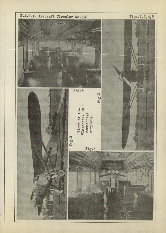
The cabin is lighted by ten windows which can be opened.
It is entered from the rear. The walls are covered with washa-
ble fabric and the floor is carpeted. tt has three ceiling
lights for night flying. Th.e equipment consists of eight chairs
with pockets and ten baggage nets (Fig. 4) on the side walls
above the heads of the Dassengers. The clock, altimeter and air-
speed indicator are in full view of the passengers (Fig. 5).
The toilet room is at the entrance to the airplane, being
converted into a vestibule on the ground.
w.A.C.A. Aircraft Circular No. 112
8
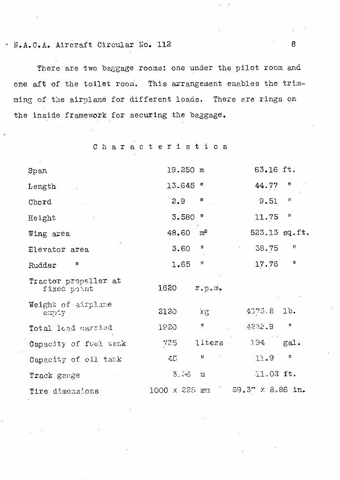
There are two baggage rooms:
one aft of the toilet room. This
ming of the airplane for differen
the inside framework for securing
one under the pilot room and
arrangement enables the trim-
t loads. There are rings on
the baggage.
Char act e r I st ± c s
Span 19.250 m 63.16 ft.
Length . .13.645 " 44.77 II
Chord . 2.9 It 9.51
Height . 3.580 " 11.75
Wing area 48.60 m 523.13 sq.ft.
Elevator area 3.60 ' 38.75
Rudder U 1.65 u 17.76 "
Tractor propeller at fixed pout 1620 r.p.m0
Weight of a:rp1ane empty . 2120 1Kg 4373. 8 lb.
Total lc.d a:c:td. 1920 Li.29 It
Oapac:tty of f1JL nk 735 liters 94 ga1
Capacity of cii.. tLk :L1.
Track gtge . m I1.O2 ft.
Tire dimen3:.ons 1000 x 22 mm 393 x 886 in.
NIPA.C.A. Aircraft Circular No. 112
9
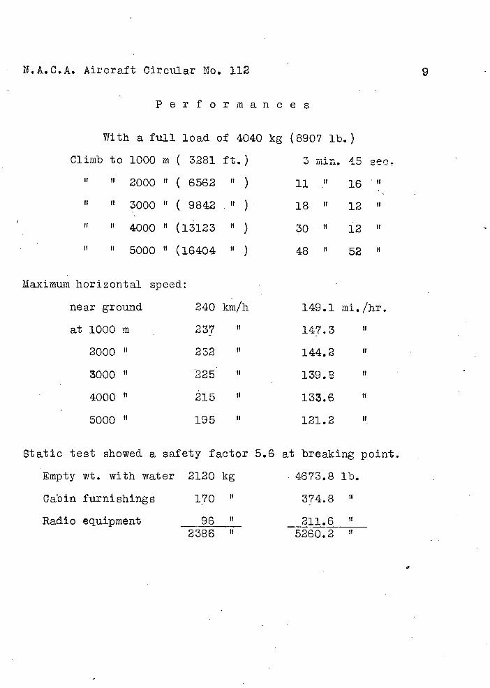
P e r f o r m a n c e s
With a full load of 4040 kg (8907 lb.)
Climb to 1000 m ( 3281 ft.) mm. 45 sect
2000 " ( 6562 ) 11 ." 16 U
II H 3000 ( 9842 ) 18 ' 12 " 'I
II U 4000 (13123 " ) 30 " 12
U U 5000 " (16404 ) 48 52 "
Maximum horizontal speed:
near ground 240 km/h 149.1 mi./hr.
at 1000 m 237 II 147.3
2000 232 " 144.2
3000 Il 225 l39.
4000 " 215 133.6
5000 " 195 " 121.2
Static test showed a safety factor 5.6 at breaking point.
Empty wt. with water 2120 kg 4673.8 lb.
Cabin furnishings 170 " 374.8
Radio equipment 96 U 211.6__
2386 5260.2
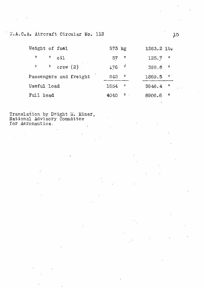
ThA.C.A. Aircraft Circular No. 112
Weight of fuel 573
H oil 57
H H crew (2)
Passengers and. freight 848
Useful load 1654
Full load 4040
Translation by Dwight M. Miner, National Advisory Comniittee for Aeronautics.
kg 1263.2 lb
H 125.7 II
388- '
U 1869.5
U 3646,4 "
IT 8906.6 '
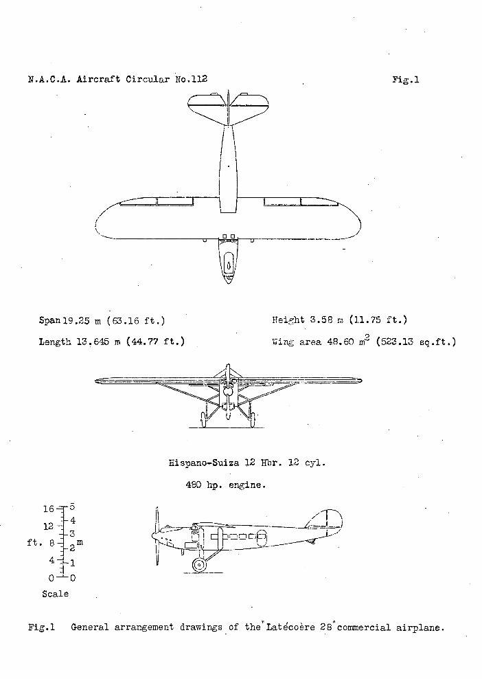
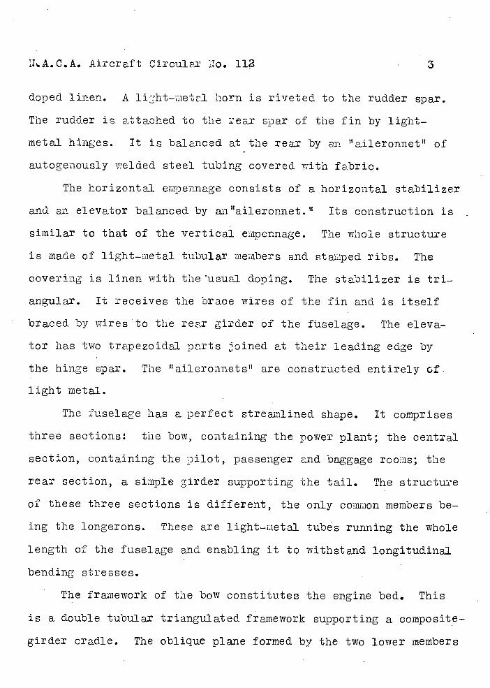
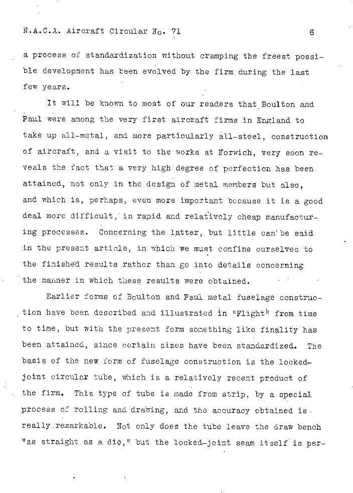
N.A.C.A. Aircraft Circular No.112
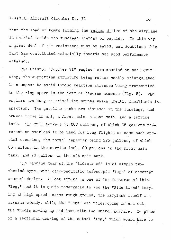
Pig.1
Spanl9.25 in (63.16 ft.)
Height 3.58 in (11.75 ft.)
Length 13,645 in (44.77 ft.)
Wing area 48.60 m2 (523.13 sq.ft.)
Hispano-Suiza 12 lFbr. 12 cyl.
480 hp. engine.
12+3
ft. 8-2m
4---1
0-i--- 0
Scale
Pig.1 General arrangement drawings of theLatcore 28 " coercia1 airplane.
AIRCRAFT CIRCULAPLS
ATIOITL AD TISORY cor:ITTEE FOR AEROUTICS
No. 71
THE BOLILTON AND PAUL lu
BOMBER AIRPLANE BRITISH)
Washington April, 1928
NATIONAL ADIfISOPLY COMMITTEE FOR AERONAUTICS.
AIRCRAFT CIRCULAR NO. 71.
THE BOULTON AND PAUL 'SIDESTRAND I BOMBER AIRPLANE (BRITIsH).*
Two Bristol Jupiter VI' Engines.
In attempting to convey an adequate idea of the new Boi4ton
and Paul twin-engined bomber which has recently gone into pro-
duction for the Royal Air Force squadrons, two ways are open:
One might concentrate on the merIts of the airplane (and they are
many) for the particular purpose for which it was designed, or
one may approach the subjet along more general lines, examin-
ing the airplane as an aircraft pure and simple, with but minor
regard to its particular function as a military weapon. In the
former case cne would merely be describing an airplane which is
a very excellent bomber, while by taking the alternative ap-
proach the merits of it as a piece of aeronautical engineering
can be examined. On the whole, we believe that the majority
of our readers are likely to be more interes-ted in the general
aerodynamic and structural features, and a.s there are certain:
restrictions which prevent a full discussion of the military
equipment, the following notes will be devoted to the general de-
sign of the !Sidestrand," bearing in mind that the airplane has
been designed as a three-seat day bomber, and that therefore
certain specified loads had to be carried, loads consisting
partly of equipment, partly of machine gun armament, and partly
of bombs. What percentage of each is involved we are not in a
*From "Flight, t March 29, 1928.
N.A.C.A. Aircraft Circular N 0 . 71 2
position to state.
Aerodynamic Design
The readers who have followed his interesting series of arti-
des on Aircraft Performance' in t1 Flight'" monthly technical
supplement ' t The Ajrcraft Engineer," will have obtained a fairly
good idea of the general design olic.y of Mr. J. D. North,
Boulton & Paul's Chie Engineer and Designer, and. in examining
the "Sdestrand" one looks, for such features as Mr. N 0 rth has
advocated in his articles. Among these perhaps none was more
prominent than the reduction;. of induced drag by having a high
value of the ratio of
and a glance at the general ar-weight
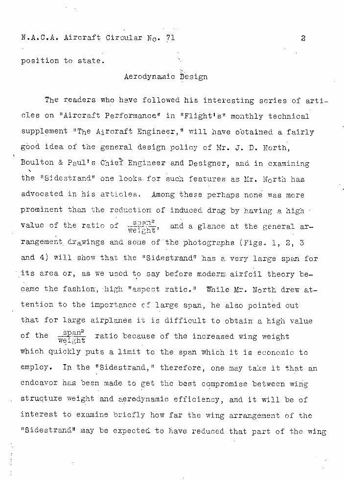
rangement drawings and some of the photographs (Figs 1, 2, 3
and 4) will show that the "Sidestrand" has a very large span for
its area or, as we used to say before moderii airfoil theory be-
came the fashion, high "aspect ratio." Thile Mr. North drew at-
tention to the importance cf large span, he also pointed out
that for large airplanes it is difficult to obtain a high value
of the
ratio because of the increased wing weight weight
which quickly puts a limit to the span which it is economic to
employ. In the "Sidestrand," therefore, one may take it that an
endeavor has been made to get the best compromise between wing
structure weight and aerodynamic efficiency, and it will be of
interest to examine briefly how far the wing arrangement of the
"Sidestrand" may be expected to have reduced that part of the wing
N..A.C.A. Aircraft Circular No. 71
- drag.which is due, as Mr. C. C. Walker ut it, to "carrying a
certain weight on a certain span at a certain speed."
The total loaded weight of the. "Sidestrand is 8850 lb.
and the span is 72 ft. The value of 9- is therefore 0.518
and the monoplane value of the raticof lift to inthiced. dreg ie
at 70 M.P.H., fdr instance, 20.31. As the gap/span ratio of the
"Sidestrand" is about 0.14, this value is increased to 25.9 for
the biplane arrangement used. Thus at 70 M.P.H. the induced drag
is only 342 lb., which is remarkably 16w and corresponds to a
thrust horsepower of 64 B.HP. only for overccming induced drag
at that speed. Since at this low speed (corresponding pobab1y
fairly well with the climbing speed of the airplane) the induced
drag is a 1age percentage of the total wing drag, it is seen
that the "high aspect ratio" wing arrangement does appear to
have oroved extrenely beneficent. The
52
value of 0.518 is weight
quite high for an airplane of this weight, and in a number of
airplanes this ratio only reaches a value of 0.3 or so We
believe that actually in the "Sidestrand" the extra wing weight
which Was the "price paid" for the •higher value of amount-
ed to some 200 lb., but at that it paid t3 carry the extra weight.
While on the subject of wing design, a few words concerning
the method used by Mr. North and his staff in the choice of wing
section may be of interest. The method was outlined by Mr. North
inhis series of articles to which reference has already been
rtiade, and. consists in starting off with a consideration of the
N.A.C.A. Aircraft Circular No. 71
4
operational conditions to be met, and then, taking as a basis a
good streamline shape, curving its center line to give the re-
quired aerodynamic characteristics, the original streamline sec-
tion •being chosen of such a thickness that it will accommodate
spars of sufficient depth. Thus, in any Boulton and Paul air-
planes, one is not likely to find iy stereotyped wing section,
although some of those in use may, more or less accidentally,
have a fairly close resencolance to certain "accepted)' sections.
Incidentally, the original streamline shape taken as the basis
is generated. by the generalized Joukowsky theory.
The wing cellule having been carefully designed to meet
the particular operational conditions of the type in question,
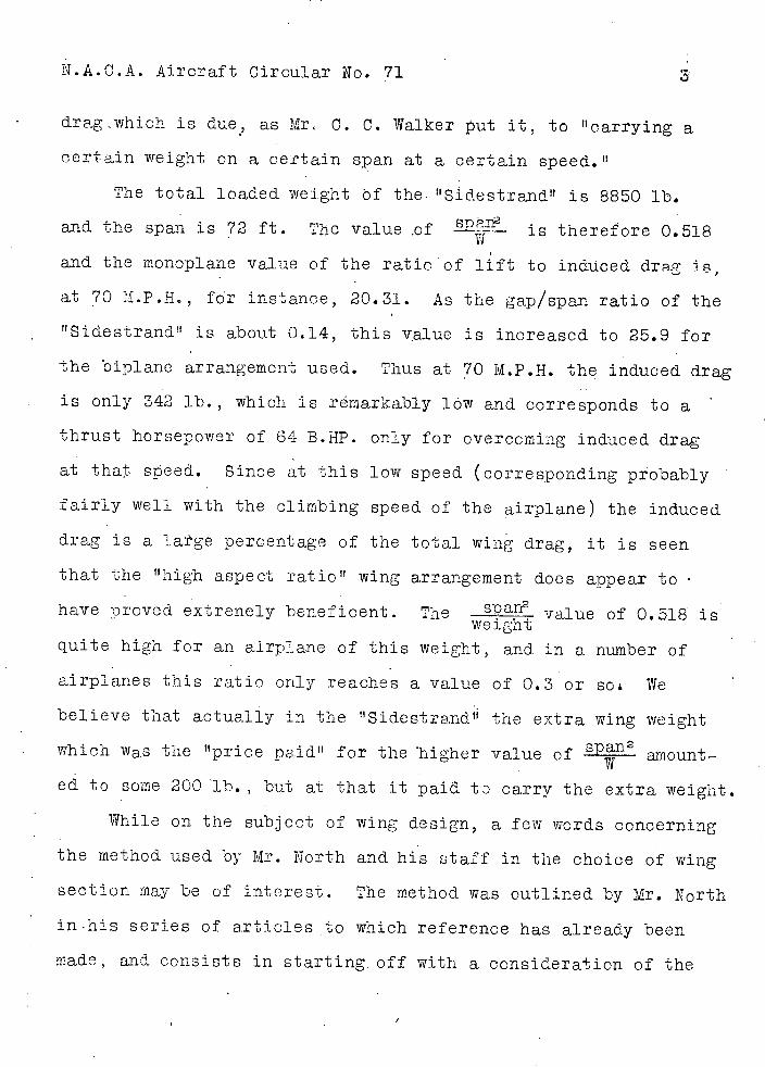
great care is again taken in the design of fuselage and engine
nacelles. In the case of the "Sidestrand," for instance, a
start was made with a body of very good streamline shape, gen-
èrated as in the case of the wing sections, a model of which was
tested in the wind tunnel. The coôkpits were then added one by
one, the drag being measured after each such addition. If a
certain cockpit shape or arrangement was found to add unduly to
the drag, modifications were made until the figure had been re-
duced. to what appeared to be the lowest practicable value. Take,
for e.xample, the prone gun position under the fuselage. Obvi-
ously this might .easily increase the body drag to a very high
figure, but by persistent experimentation the drag caused by
this gun emplacement was ultimately reduced to a very lQw value,
indeed.
Aircraft Circular N 0 . 71
5
The engine nacelles were, the suje.ct of similar ree.aroh
and the form finally chosen, which is well shown in several of
our photographs, has given about as low a drag as it is possible
to attain with engines placed outboard The research included
wind tunnel tos1 with model proDellers running, and at large
angles, it having been found that the "interference dragH is
largely an induced drag and liable to be greater at large angles,
thus affecting performance on climb etc.
The landing gear design (Figs. 7 and 8), although perhaps
more of a structural than an aerodynamic problem, also shows
this striving for aerodynamic "cleanness," the landing gear of
the "Sidestranci" being of remarkably low frontal area for an
airplane of this size.
Altogether the Boultori and Paul "Sidestrand" is an airplane
which well repays a close study, the results of the very great
care taken in its aerodynamic design being reflected in the per-
formance figurs which will be found at the end of this report.
Structural Dein
If the aerodynamic design of the Sidestrand" is of more
than usual interest, the same applies at least as much to the
structural features. Although in what follows the reference is
particularly to the "Sidestrand," most of the constructional
details are now standard Boulton and Paul prac'tiôe, and would.
apply fairly closely to any airplane built by that firm, since
N.A.C.A. Aircraft Circular No. 71 6
a process of standardization without craiping the freest possi-
ble development has been eto1ved by the firm during the last
few years.
It will be known to most of our readers that Boulton and
Paul were among the very first aircraft firms in England to
take up all-metal, and more particularly all-stéel, construction
of aircraft, and a visit to the works at Norwich, very soon re-
veals the fact that a very high degree of perfection has been
attained, not only in the design of metal members but also,
and which is, perhaps, even more important because it is a good
deal more difficult,'in rapid and relatively cheap manufactur-
ing processes. Concerning the latter, but little can be said
in the present article, in which we must confine ourselves to
the finished results rather than go into details concerning
the maimer in which these results were obtained.
Earlier forms of Eoulton and Paul metal fuselage construc-
tion have been described and illustrated in fl Flight it from time
to time, but with the present form sOmething like finality has
been attained, since certain sizes have been standardized. The
basis of the new form of fuselage construction is the locked-
joint circular tube, which is a relatively recent product of
the firm. This type of tube is made from strip, by a special
pocess of rolling and dra7ing, and the accuracy obtained is
really.emarkable. Not. only does the tube leave the draw bench
"as straight as a die," 'cut the locked-joint seam itself is per-
N.A.C.A. Aircraft Circular No. 71
fectly uniform and straight, i.e.., there is no twist in the tube.
This is important because of the attachment of the fittings, for
which it is desirable to know exactly where the seam is going to
come, and that it will be i the same place at all fittings.
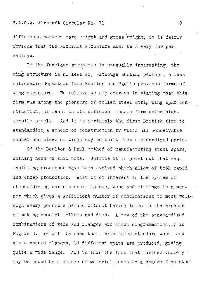
Having evolved an eminently satisfactory type of tube for
longerons and struts, standardized in a certain number of sizes,
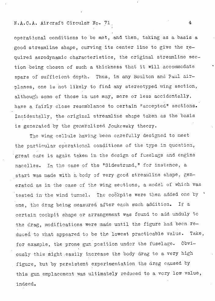
the next step was to design a neat type of fitting for the attach-
ment of struts to longerons. How the problem was ultimately
solved is indicated in Figure 5. A tubular upad tt of magnesium
alloy, fitting snugly over the tubular longeron, and with flat
faces machined on the outside, gave the solution. Bolts pass
through t!padu and longeron vertically and horizontally (being,
of course, slightly staggered in relation to each other), the
strut ends being attached to the bolt heads and the bracing wires
to sheet steel links 01' wiring plates in the manner shown. The
bolts themselves are of duralumin, and bushes are interposed be-
tween them and the walls of the longerons to increase the bear-
ing area. The arrangement will be clear from Figure 5. By the
employment of magnesium alloy 'pads' t , and duraluniin bolts, the
weight of the fuselage fittings is kept down to a very low fig-
ure, while certainly the locked-joint tubes, of high-grade steel,
are lighter than any drawn tube could be. The result is a struc-
turally very economical constriction. We regret that we have
no figures relating to the bare structure weight of the "side-
strand" but knowing the amount of equipment carried, and the
N.A.C.A. Aircraft Circular No. 71
8
difference between tare weight and gross weight, it is fairly
obvious that the aircraft structure must be a very low per-
cent age
If the fuselage structure is unusually interesting, the
wing structure is no less so, although showing perhaps, a less
noticeable departure from Boulton and Paul's previous forms of
wing structure. We believe we are correct in stating that this
firm was among the pioneers of rolled steel strip wing spar con-
struction, at least in its efficient modern form using high-
tensile steels. And it is certainly the first British firm to
standardize. a scheme of construction by which all conceivable
manner and sizes of wings may be built from standardized parts.
Of the Boulton & Paul method of manufacturing steel spars,
nothing need be said here. Suffice it to point out that maiu-
facturing processes have been evolved which allow of both rapid
and cheap production. What is of interest is the system of
standardizing certain spar flanges, webs and fittings in a man-
ner which gives a sufficient number of combinations to meet well-
nigh every possible demand without having to go to the expense
of making soecial rollers and dies. A few of th standardized
combinations of webs and flanges are shown diagrammatically in
Figure 6. It will be seen that, with three standard webs, and
six standard flanges, 18 different spars are pioduced, giving
quite a wide range. Add to this the fact that further variety
may be added by a change of material, even to a change from steel
I'T.A.C.A. Aircraft Circular N 0 . 71 9
to duralumin, and it Will be obvious that the range immediately available is very wide.
Incidentally, the accuracy of production i.s within 0.01 in,,
thus ensuring complete interchangeability, which is even more
important from the point of view of mass production than repairs.
It might here be mentioned that all Boulton & Paul strip is
formed in the soft state, and hardened and tempered after form-
ing.
The rib design is very simple, and consists of channel
flanges and tubular distance pieces forming the girder webs.
This applies to the normal rib. At points where heavier stresses
have to be withstood, modified forms are used, also of channel
section, but with larger channels, and with channel section dis-
tance pieces. Several types are shown in Figure 6.
The attachment to the spars of internal drag struts and
interplane struts is effected via bridge pieces in such a manner
as to impose no crushing stresses on the thin-walled spars, the
loads being taken either on the bridge pieces or on bolts pass-
ing through the distance tubes in the spars.
Without being a. very detailed description of the construc-
tion of "Sidestrand,'t the above notes should give a general idea
of the types of structure employed. Ir the absence of an expla-
nation of the internal arrangement of the fuselage, which would
necessitate a reference to equipment of a military nature, about
which nothing may be said, we must confine ourselves to stating
N.ACA. Aircraft Circular No. 71
that the load, of bombs forming the raison d'etre of the airplane
is carried inside the fuselage instead of outside. In this way
a great deal of air resistance must be saved, and doubtless this
fact has contributed materially towards the good performance
attained.
The Bristol "Jupiter VI" engines are mounted on the lower
wing, the supporting structure being rather neatly triangulated
in a manner to avoid torque reaction stresses being transmitted
to the wing spars in the form of bending moments (Fig. 5). The
engines are hung on swivelling mounts which greatly facilitate in-
spection. The gasoline tanks are situated in the fuselage, and
number three in all, a front main, a rear main, and a service
tank. The full tankage is 260 gallons, of which 35 gallons rep-
resent an overload to be used for long flights oi' some suc.h spe-
cial occasion, the normal capacity being 225 gallons, of which
65 gallons in the service tank, 90 gallons in the front main
tank, and 70 gallons in the aft main tank.
The landing gear of the "Sidestrand" isôf simple two-
wheeled type, with oleo-pneumatic telescopic "legs" of somewhat
unusual design. A long stroke is one of the features of this
"leg," and. it is quite remarkable to see the "Sidestrand" taxy-
ing at high speed across rough ground, the airplane itself re-
maining steady, while the "legs" are telescoping in and out,
the wheels moving up and down with the uneven surface. In place
of a sectional drawing of the actual "leg," which would have to
D
N.AC.A. Aircraft Circular N0 .71
11
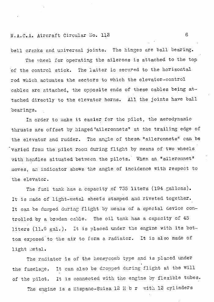
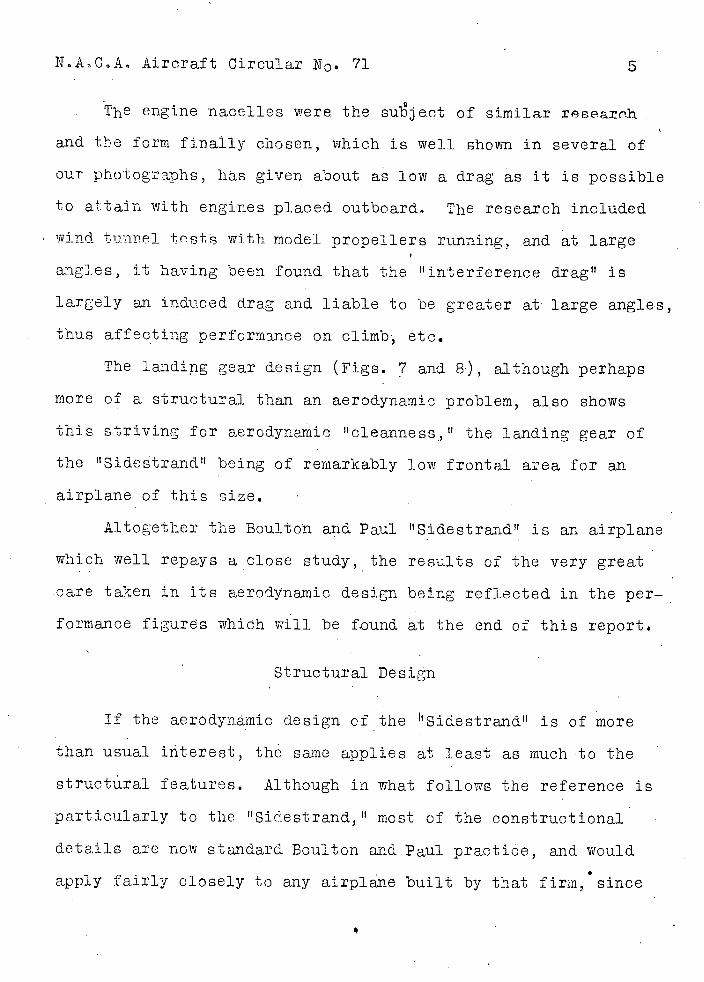
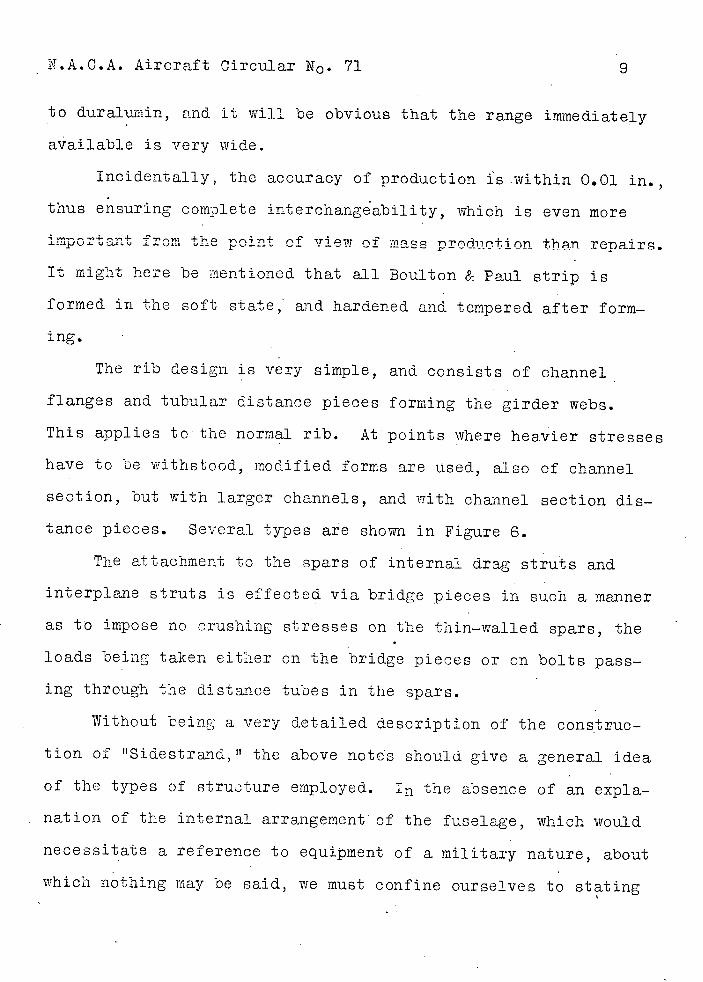
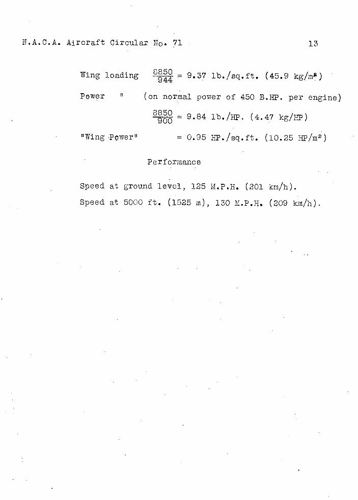
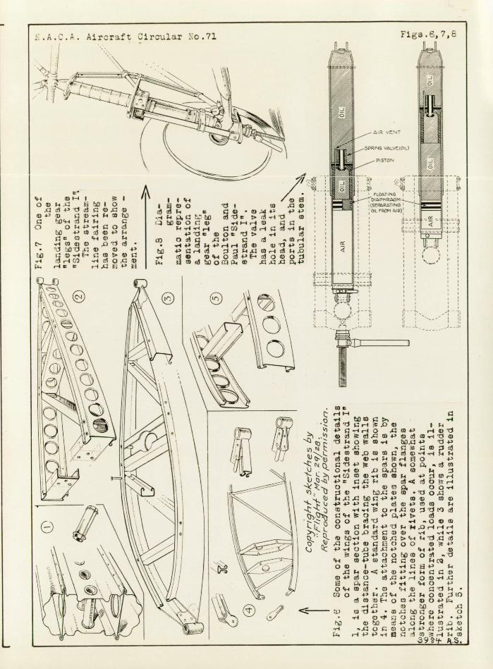
be of a highly technical nature, we publish a diagrammatic repre-
sentation which will serve to illustrate the general principle
upon which the "leg" is designed (Fig. 8).
The lower portion of the "leg" is filled with air (pumped in
at an initial pressure of 125 lb./sq.in.), and the upper part
with oil, a floating diaphragm separating the air from the oil.
A piston is attached to, and moves up and down with, the lower
part of the leg. This piston has in its head a valve seat and a
spring-loaded hollow-stem valve. Th is hollow or cylindrical
stem is provided with ports, so that when the valve opens, the
oil can pass through from one side of the piston to the other.
I the valve head is a small leak hole. This, of course, permits
oil to pass through under all conditions.
When the "leg" is subjected to a load, the air is compressed
by the upward movement of the lower half. If the movement is a
relatively gentle one, oil merely leaks through the small leak
hole in the valve head. When a certain speed of travel is
reached, however, the valve opens against the action of its
spring, and the oil is then permitted to flow through the ports
in the valve stem, from the space above the piston to the space
below it. The size of leak hole and ports has been carefully
proportioned so as to give, in conjunction with the compressed
air and the pneumatic tire, a deflection diagram of the right
shape. In taxying, the damping of the oil is such as to prevent
any tendency to bouncing, and the airplane travels along on an
N.A.CA. Aircraft Circular JT0. 71 12
even keel, although on rough ground the wheels may be seen to be
moving up .nd down rapidly, following tha irregulari.t.ies of the
ground. The small air vent pipe shown may possibly pass a small
amount of oil during the travel of the leg,U but its chief func-
tion is to avoid the formation of an air lock while the "leg" is
being filled with oil. The jack shown in the diagrams and in
Figure 7 can be used for extending the "leg," or for tire chang-
ing, etc., as well as for relieving the "legs" of load when the
airplane is standing in a shed for long period.
Specifications
Lengti .................4Oft.8in.
Span.................. 72 U 0 n
Areas:
Total wing areas . 943.5 sq.ft.
Ailerons ............142.0
Stab i l i ze r ...........68.6 U
Elevators ..............50.7
Fins ..............11.0 "
Rudder..............31.8
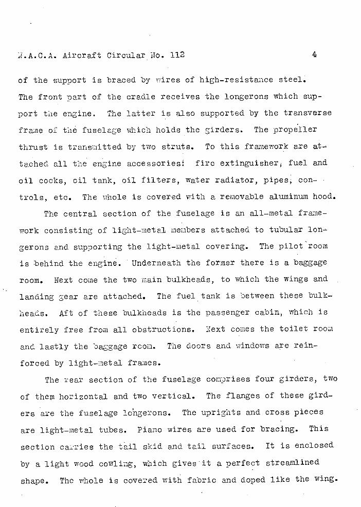
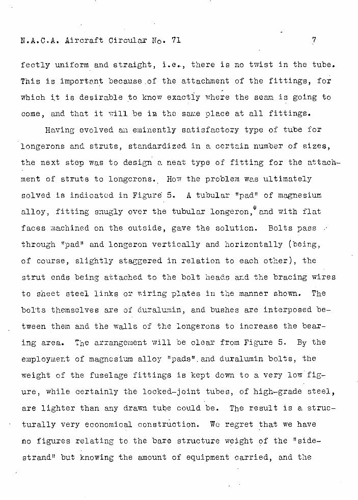
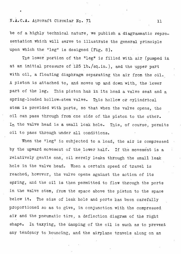
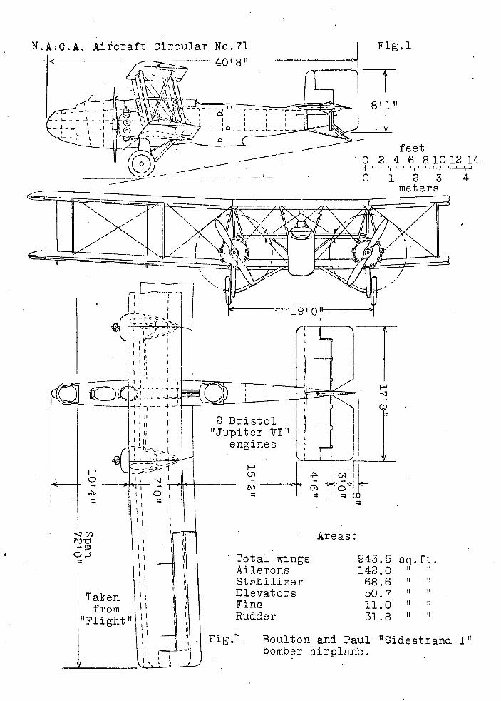
The main dimensions of the 'Sidestrand I" are shown in
Figure 1. The weight of the airplane light, is 5275 lb. (2400
kg), and the load carried is 3575 lb. (1625 kg), giving a total
loaded weight of 8850 lb. (4025 kg).
N.A.C.A. Aircraft Circular No. 71
13
850 - 1b./sq.ft. (45.9 kg/ms ) Wing loading
Power ' (on normal power of 450 B.HP. per engine)
8850 = 9.84 lb./}. (4.47 kg/I) 900
ttWing-Pwertt = 0.95 HP./sq.ft. (10.25 :/m2)
Performance
Speed at ground level, 125 M.P.H. (201 km/h).
Speed at 5000 ft. (1525 in), 130 M.P.H. (209 km/h).
N.AC.A. Aixcraft Circular No.71
Fig.'
40'S"
St
8' 1"
.--•
feet
} -- . 0 2 4 6 8101214
r i ') 7 A ¼) J. ¼)
fli p 1-. p v
r4
H-
I I
F-
o I
- -
OIl=
c
Taken froni III
_ilj
2 Bristol "Jupiter VI"
engines
H
C',
Areas:
• Total wings 943.5 eq.ft. Ailerons 142.0 " " Stabilizer 68.6 " " Elevators 50.7 Fins 11.0 " Rudder 31.8 "
Fig.l Boulton and Paul "Sidestrand I" bomber airplarfe.
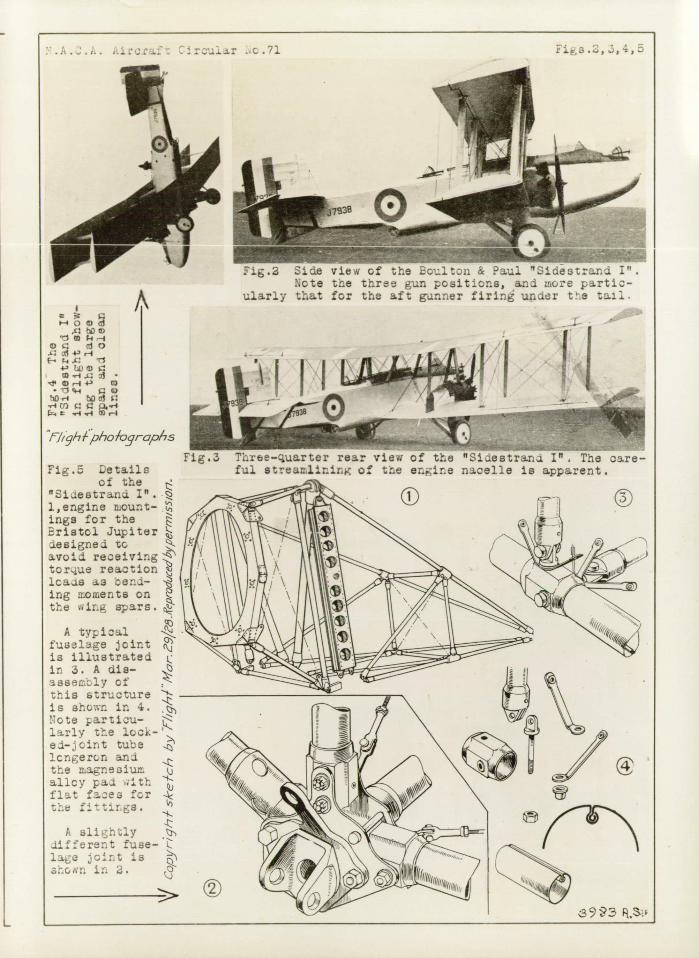
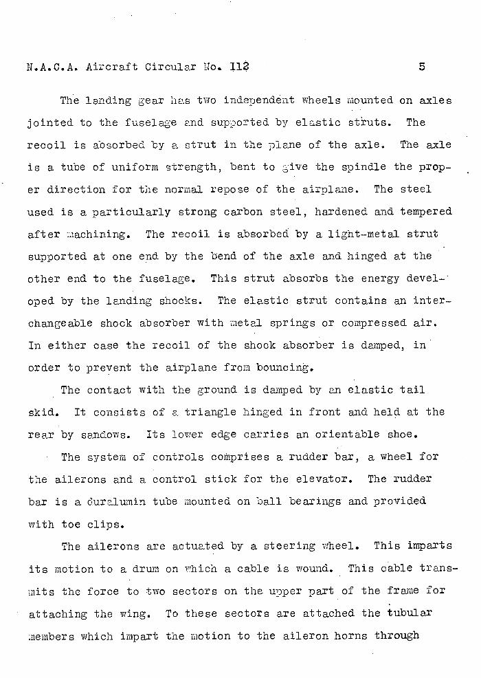
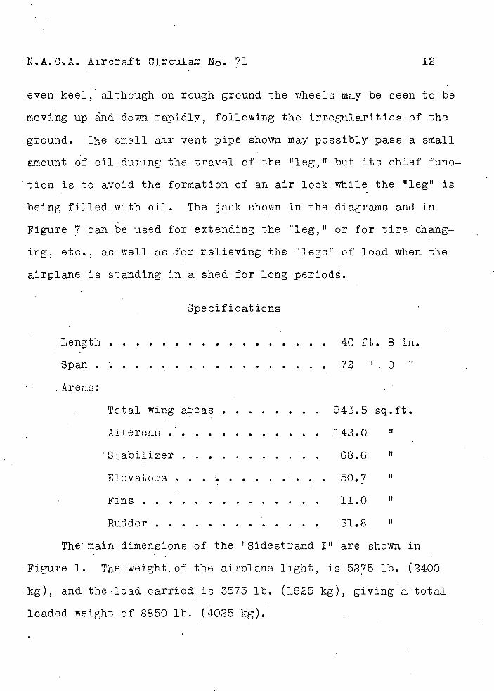
____ • S Fig.3 . .r vi of the "Si.estrir..j 1r
fu. of t:e erine na.celle is apprent.
:ruir .c.71
___ - iie cf :he _1tcn & u S1destranzi 1H•
..cte t:e tr.rt r- positions, and more partic-ularly that for the aft gunner firing under te tail.
0
.4 1 o
i 4' ,-1 F-.
TI 4' JDD I
'cIø,-l4' CO • 1i ø
F-. ..-4,-4 O.-•4
rJighfpho/ogrcphs
Fi.5 Letails
of the "Siestr3nci l,engine nount- . ings for the Erieto]. Jupiter aesignei c avoid receiving tor.jue reaction lcaia as en-ing noments on the uir.g spars.
A typic]. fuaslge joint is illustrated L in 3. A die-3ssenbly of - this structure - is 8h07.c in 4. Note particu-l.r1y the lock-e.-jcnt tube 1cngern ana the n.agneoiun alloy pai ;.th flat fae for the fitrs.
A slightly '. J.ifferent fuse-lac ;cirt is
i 'j.
I >
.A.O... Aircraft Circular o.7l Figs.6, 7,
t' rit -
11
o4t- ft 0 £ cti 4-' d j .i
D 4-'D 4-)-4c-4bD 4-4
o 00ci
q-la, c. N- •- W $1) L)T c1
• is ) 4' ir-4O .rcT%O,
w • (1).144' -P4-'
(15d -l'1 (0 I(1)0(Q) ,-fl--4-i(1)
1 'ri c:cI) (d-1 03•.-4 4 4'd d ..-i 6
(3) O(1 .(T4-' 13 (flr4 • 4 4-' (1 ;-4 4-' r-I r4 03 (1) q o1.' i
4-' Cr113 i S 44 C),-I 03 -.-4 (13• V0034'0300 1. U(0cd)0U)Il4(0 •:.t::•i.+)
•.-4 —I • rjr-4.0a) I -4 ') 4.' 4 r-4 3 (fl 4-' rI a
.•") aC W4-' L1 O.-4d D '10W'-4 bjjE4-' di.'
4-4t -' -L OW -..-4k.4
Gj) )-ir-4fl0 4' rji-'
J .-o-4a O0..L (0 i :1 4'1W-4
c.1::t4 130r-4 * -. 0 .-I4' 11) ), 0 0
£0. i) Q)W •d0.3
) cbO4'4-' (0(l) (0(l) j - 4.' 4-' .-I ai Q) 4-' fl (1)
iQ )dr')oj e-iC) 4.'0.4-' (13
00 d '-4 .0(0 0 t4+'d-44-4r--4r-1
> 0o)(l ,-4 .•-1,-I DbC.-4 41-4'E3
4'(lciO00 (l4' (j O)aLC4' i-+' (l
(li4'OOc0Oii .d t.4 (04' (l) 4(Q o I 4' -44' t
(lJ-. 4-' (1)4-' --4 i-i (l4'Ld0 44'-i0a)'-I-
i-'i-4 ,-i0 4-' o -i (0 • a - U) 0 4' 1-I(1l-4 -. 0(1) ;ito
m -" E-' 0 C) 4' (1) 04-' -.-i. () -A 1
Li) i ti 4-) • (fl ) .4 0 • r4 O 00l4' .4-,
VO 4'0))(l) —I . .l U 1) 0 -4 4-' £ i •.-4 .
,
_5PRNG
TPST;: 'LOATNG
DAPHPA&3M-SRTING 01
ia_ -
____ -
I
i.