Embed Size (px)
Citation preview
メカロック®
MCアルミ合金
SUS304
無電解ニッケルメッキ
MA
MB
機械構造用炭素鋼
MT
MR
MSA
MSR
MN
MKA
MKT
MKR
MKN
ラインアップ
Lineup
使用実例
Usage exam
ples
選定設計ガイド
Selection G
uide
15 16
メカロック®
STEP
1STEP
4選定設計ガイド
Selection G
uide for Mecha-lock series
メカロックシリーズ全製品対象
1
2
3
4
機械製作において、基本となる要求事項を整理する。Confirm your desired specifications that are based on manufacturing machines.
要求仕様チェック Checking required specifications
STEP
2動力発生源(油圧、空圧、電動、エンジンなど)を検討し、効率の良い機構を決定する。要求精度に対して、機構、制御の両方で満足するかを確認する。Decide on an efficient driver such as hydraulics, pneumatics, electric drive, engine, etc. Confirm the structure and the control suited for achieving the required accuracy.
If shaft has a key seat, torque will be reduced by area of non-contact surface between shaft and Mecha-lock bore.
トルク、スラストの合成負荷がかかる場合は下記の一般的な計算式によって計算し、メカロック最大許容トルクと比較して下さい。Calculate by using standard formula below when there is a torque and thrust combined load, and compare with maximum allowable torque capacity of Mecha-lock.
モータ容量(出力)と減速機構の有無、及び減速比が決定したらモータトルク曲線と回転数から発生トルクを算出して下さい。モータメーカー資料がない場合は下記の一般的な計算式によって計算して下さい。Calculate the generated torque by motor torque line and RPM when you set the motor capacity, with or without reduction gear, and its reduction rate. If there is no manufacturer’s information for the motor, then please use the standard formula below.
動力伝達機構の決定 Selecting the transmission method
STEP
3 駆動源選定(モータの場合)Selecting the driver (in case of motor)
仕 事
スペース
周辺環境
そ の 他
1 メカロックを複数個使用する。(MT、MKTのみ)
→ 物体の移動に必要な力 ・ 移動量タクトタイムを確認する。
→ 機械またはユニットにおける幅(W)、高さ(H)、奥行(D)を確認する。
→ 温度、湿度、雰囲気などの条件を確認する。
→ 上記以外の制約を確認する(耐用年数、寿命など)。
Tmax = (R)・ K9550 ・ PmaxN
Tmax
Pmax
N
:
:
:
発生トルク[N・m]
モーター容量[kW]
回転速度[min-1]
Generated torque
Motor capacity
Rotation speed
R:減速比逆数(減速機出力軸取付の場合のみ)Reverse number of reduction rate (only for reduction gear with output shaft)
K:安全係数(下記表参照)Safety factor (refer to the table below)
Shaft material yield stress
Ts
H
d
K
:
:
:
:
合成負荷[N・m]
スラスト荷重[N]
軸径[mm]
安全係数
Combined load
Thrust load
Shaft diameter
Safety factor
メカロック入力 トルク値 Tmax メカロック最大許容トルクInput torque value of Mecha-lock Maximum allowable torque capacity
安全係数 K Safety factor
慣性 小
慣性 中
慣性 大
モータの定格トルクの60%以下で使用の場合
加減速の時間が長く、反転駆動の頻度が少ない場合
急激な減速や衝撃、正逆転の頻度が高い場合
Small inertia
Medium inertia
Large inertia
Under 60% of motor rated torque
In case acceleration/deceleration time is long and reverse motion is not frequent
In case of rapid deceleration, impact and frequent reversing
負荷の条件 Load condition
1.5-2.0
2.0-3.0
3.0-5.0
K
Ts = 9550・Pmax 2 2
N・ K+
H・d
2000
トルク Torque
軸・ハブ仕様確認 Checking shaft and hub specifications
軸 Shaft
メカロックの数量により許容伝達力は比例して大きくなります。(複数使用の場合はハブ外径が異なりますので注意して下さい)Mecha-lock can increase the transmission torque capacity by increasing quantity. (Hub outer diameters will be different if several Mecha-lock units are used.)
2 メカロック内径面及び軸表面を脱脂する。
許容伝達力が10~20%向上します。(注)テーパ面及びメカロック外周面は脱脂しないで下さい。10 to 20% of transmission torque can be increased. Note) Taper surface and outer ring of Mecha-lock should not be degreased.
3 メカロック特注品を使用する。
Use several Mecha-locks (only for MT, MKT)
Remove grease on the bore of Mecha-lock and the shaft surface.
Customized Mecha-lock
アイセルでは顧客要求に沿った製品を設計、製作致しますのでご相談下さい。Please contact us for customized products. ISEL designs and manufactures suitable specifications.
トルクアップ Torque up参考
トルクダウン Torque Down参考
1 軸にキー溝がある場合、軸とメカロック内径非接触面の面積分トルク低下します。
If Mecha-lock has been fully degreased, the screw axis force could be extremely reduced with more than 30% of transmission torque down from the catalog specifications.
2 メカロックを完全脱脂するとボルト軸力が極度に低下し伝達力がカタログ値の30%以上下がることもあります。
Oil and grease which include additives to reduce friction could decrease
over 50% of transmission torque compared to the catalog figures if they
have been applied to the bore of Mecha-lock and the shaft surface.
Shaft fit tolerance and surface roughness
3 メカロックに塗布する油、グリスの種類によって、摩擦を極度に減少させる添加剤含有品が軸やメカロック内径面に付着するとカタログ値の50%以上下がることもあります。
メカロック入力スラスト荷重値 メカロック許容スラスト荷重Input thrust load Maximum allowable thrust load
メカロック入力合成負荷 Ts メカロック最大許容トルクInput combined load of Mecha-lock Maximum allowable torque capacity
スラスト Thrust
トルク、スラスト Torque & Thrust
スラスト荷重がかかる場合は荷重方向に対してメカロックのボルト側から入力される様に設計して下さい。If there is a thrust load, please design for thrust coming from Mecha-lock’s
screw side.
Point
特にメカロックMSA、MSRなど、ステンレス製品は焼き付きにも注意が必要です。Please be aware that Mecha-lock stainless types such as MSA and MSR
can seize.
Point
MA、MSA、MKA、MR、MSR、MKRは対向で2個使用可能ですが取り外しが困難になる場合があります。2 pcs can be installed in opposite positions for the MA, MSA, MKA, MR,
MSR, MKR. In this case, uninstallation could be difficult.
Point
Point
限度Limit
表面粗さSurfaceroughnes推奨
Recommended
軸はめあい公差Shaft fit toleranceシリーズ
Series
MAMSAMKAMBMTMKTMRMSRMKRMNMKNMC
h7
h9
h8
h7
Ra1.6
δ 0.2:軸材料降伏点応力[N/mm2]
Coefficient
* C =0.6 for MT series
* C =0.8 for use of 2 MTs
C:係数 C =1.0
※MTシリーズの場合 C =0.6
※MT 2個利用する場合 C =0.8
The maximum hollow shaft bore size
Shaft diameter
Mecha-lock shaft surface pressure
d1
d
P
:
:
:
中空最大内径[mm]
軸径[mm]
メカロック軸側面圧[N/mm2]
d1 ≦ d × δ 0.2 - 2PCδ 0.2
ハブ Hub
メカロックのカタログ記載軸側面圧値×1.2以上の降伏点応力(または耐力)を有する材料を選定して下さい。※MT及びMRシリーズは1.4以上Select material having shaft contact surface pressure number greater than 1.2 times the yield point stress figure specified in the Mecha-lock catalog.*Select material over 1.4 times yield point stress for MT and MR series.
アルミ、鋳鉄ハブを使用する場合、メカロックは高い面圧のため、ハブ肉厚が薄い場合や、強度の低い材質を選定するとハブが拡大、または割れる恐れがあります。鋳鉄―引張強さ249Mpa以上の材質を推奨します。アルミ―引張強さ245Mpa以上の材質を推奨します。MBシリーズは高面圧のため、アルミ、鋳鉄の材質は適しません。Mecha-lock’s high contact surface pressure could enlarge the hub or crack it in case the hub material is aluminum or cast iron and is thin, or of low strength. Cast iron ̶ material over 249MPa tensile strength recommended. Aluminum ̶ material over 245MPa tensile strength recommended.Aluminum or cast iron material is not suitable for MB series because of its high contact surface pressure.
メカロックのカタログ記載、ハブ側面圧値×1.2以上の降伏点応力(または耐力)を有する材料を選定して下さい。※MTシリーズ及びMRシリーズは1.4以上Select material having hub contact surface pressure number greater than 1.2 times the yield point stress figure specified in the Mecha-lock catalog.*Select material over 1.4 times yield point stress for MT and MR series.
1 軸のはめあい公差と表面粗さ
1 ハブの材質Hub material
2 軸の材質
使用する軸材料の降伏点応力(または耐力)より、下記計算式にて最大内径を算出して下さい。Calculate the maximum bore size by the following formula if a hollow shaft is chosen for Mecha-lock installation.
3 中空軸最大内径
Shaft material
The maximum hollow shaft bore size
Check the transfer load, distance and takt time of the workpiece.
Confirm the machine or unit size (width, height and depth).
Check the temperature, humidity and environmental conditions.
Check other conditions (durability, unit service life, etc.).
Work
Space
Others
振れを少なくしたい場合はh6を推奨します。For minimizing off-centering, h6 is recommended.
(例) 2個→2倍 3個→3倍(Examples) 2 pcs → 2 times 3 pcs→ 3 times
Surroundings
要求仕様チェックChecking specifications
選定終了Selection made
P.15
STEP
1
動力伝達機構の決定Selecting the transmission method
P.15
STEP
2
駆動源選定(モータ等)Selecting the driver (motor, etc.)
P.15-P.16
STEP
3
軸 ・ ハブ仕様確認Checking shaft and hub specifications
P.16-P.17
STEP
4
メカロックシリーズ選定Selecting a Mecha-lock
P.17
STEP
5
負荷確認Checking the load
P.18
STEP
6
最終チェックFinal check
P.18
STEP
7
購入価格確認Checking purchase price
P.18
STEP
8
メカロックご利用上の注意事項Precautions on use of Mecha-lock
P.19-P.20
STEP
9
※√内がマイナスになった場合は 利用ができません。* Not available if the value inside√ is negative.
※軸の推奨はめあい公差でφ35のみ+0.010公差(MN、MKN、MT、MKT、MC除く)※The recommended shaft fit tolerance is +0.010 for φ35 only. (Except for MN, MKN, MT, MKT and MC)
メカロック®
MCアルミ合金
SUS304
無電解ニッケルメッキ
MA
MB
機械構造用炭素鋼
MT
MR
MSA
MSR
MN
MKA
MKT
MKR
MKN
ラインアップ
Lineup
使用実例
Usage exam
ples
選定設計ガイド
Selection G
uide
17 18
メカロック®
STEP
5
選定設計ガイド
Selection G
uide for Mecha-lock series
メカロックシリーズ全製品対象
メカロックシリーズ選定 Selecting of Mecha-lock series
STEP
6 負荷確認 Checking the load
STEP
7 最終チェック Final Check
MT、MKTシリーズのハブ加工の注意事項 軸 ・ ハブ挿入深さ Installation depth of shaft and hub
バランス Balance
MN、MKNシリーズのハブ幅が取れない場合の設計上の注意点
Point
軸挿入深さはメカロックを貫通するのが理想ですが、短い場合でもメカロックテーパ部以上(フランジやナットに軸端面がかかる位置)までは必ず挿入して下さい。挿入不足の場合製品が塑性変形し、再使用できないことがあります。ハブはモーメント許容や取付を考慮して、メカロック挿入深さを決定して下さい。(段付加工によりハブ端面からボルトが突出しない方法や、ラジアル荷重中心点にメカロックが入るなど、色々工夫し加工して下さい。)※MRシリーズ、MNシリーズは内輪の長さ以上挿入して下さい。It is recommended that the shaft goes through the Mecha-lock. But please confirm that the shaft reaches the taper point (point where the flange or nut reaches the shaft edge). If it does not, the Mecha-lock can deform and be unsuitable for reuse.Decide the shaft installation amount to hub considering the moment capacity and installation process (for example processing to hide the screw head from the hub edge and use the Mecha-lock in the center of the radial load).*For the MR and MN series, shaft insertion should be longer than the inner ring length.
MA、MCシリーズはL4寸法
MTシリーズ、MRシリーズはL3寸法
MNシリーズはL2寸法
B =
MA and MC series is in L4 size.
MT series and MR series are in L3 size.
MN series is in L2 size.
Fig.7Fig.6
Pir = 1.5 × Rd × B
≦ 0.2 × P
Por = 1.5 × RD × B
≦ 0.2 × P
R
P
d
D
B
:
:
:
:
:
ラジアル荷重[N]
軸、ハブ面圧[N/mm2]
軸径[mm]
ハブ内径[mm]
接触長さ(※)[mm]
L1B
Fig.5
ラインアップページ(P9~P10)を参照いただき、用途、スペース、作業性、特長等から最適なシリーズを選定して下さい。(各シリーズの先頭ページに特長が記載してあります。)無電解ニッケルメッキ・ステンレスのバリエーションを追加し、アルミプーリ用アルミメカロックをラインアップしました。Select the suitable Mecha-lock considering the application, space, operation, specification, etc. with lineup page. (P9-P10) (The features of each Mecha-lock are at top of each page.)Electroless nickel plating and stainless types are added. Also aluminum Mecha-lock for aluminum pulley has been introduced.
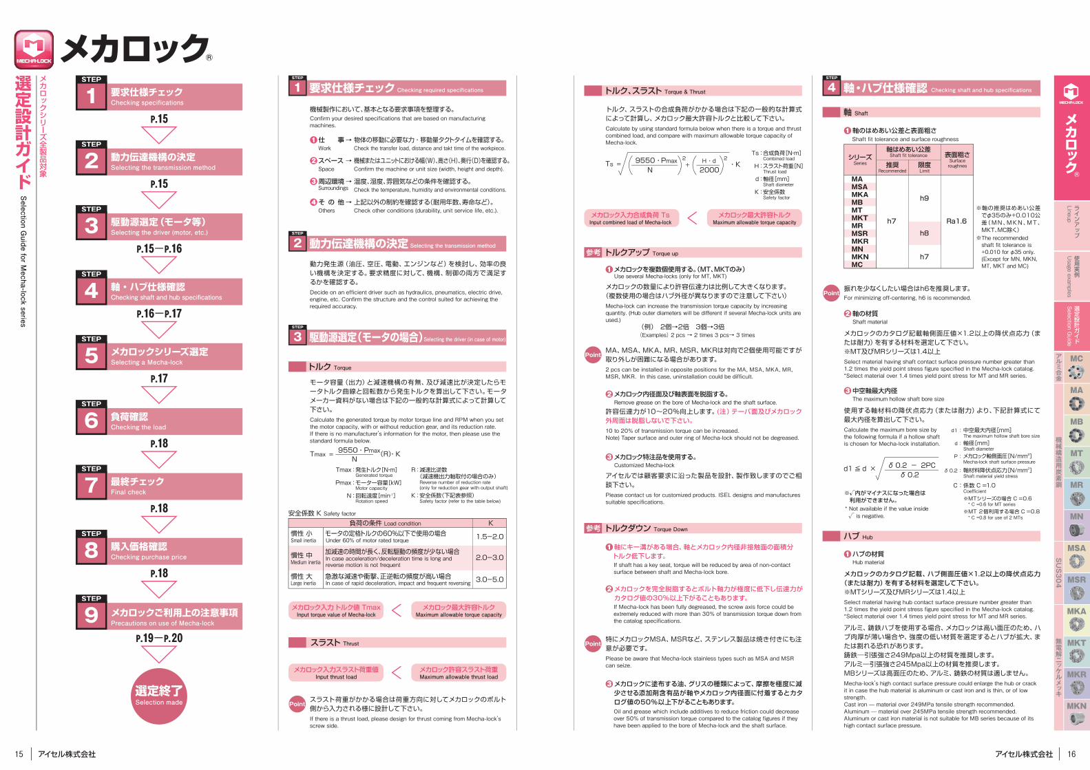
ラジアル方向の荷重がメカロック外径部にかからない場合(Fig.6)の使用ではメカロックに曲げモーメントの荷重がかかり、軸のスリップまたは軸、メカロック破損の要因となります。 ハブ形状の変更(Fig.7)または、メカロック締結位置をラジアル荷重を受けられる位置に移動します。ハブガイド部を軸に接する部分を多くし、曲げモーメントを受ける対策も有効です。 If radial direction load is not on the outer diameter of Mecha-lock (Fig.6), a bend moment is created on Mecha-lock due to the increased contact area between hub and shaft, resulting in shaft slippage or shaft/Mecha-lock damage. So move the Mecha-lock connection location to a position capable of withstanding radial direction load. Also enlarge the hub guide section in contact with the shaft to withstand bend moment (Fig.7).
メカロックは正規の使用をした場合、30回以上の着脱が可能ですが、ボルトネジ面、座面が荒れることで軸力が3回目以降、徐々に低下します。100%の性能を求められる場合には3回目以降は新品のボルトに交換して下さい。※ボルトは弊社専用品をご使用下さい。A Mecha-lock may be used more than 30 times provided it has been correctly installed and used in normal operation conditions. Screws and surfaces do become scratched so that shaft specs may slowly deteriorate after being reused twice so that replacement of screws are recommended to maintain 100% performance.*Use the screw specified by ISEL.
1
メカロックは原則として曲げモーメントを受けることはできません。ハブ形状の選定とメカロックの荷重を受ける位置を変更して頂くことで採用が可能となります。Basically Mecha-lock cannot withstand a bend moment. However Mecha-lock can be used by changing the load receiving location or design of hub.
メカロックに曲げモーメントの荷重がかかる場合Bend moment to Mecha-lock.
までの適合に問題がないか再確認して下さい。問題がなければ次の項目をチェックします。
メカロック選定及び詳細仕様の適合確認をします。
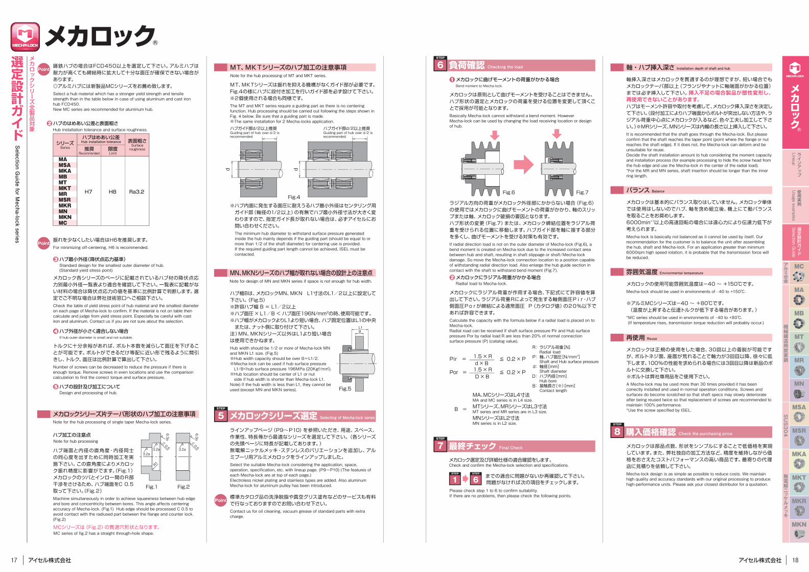
MT、MKTシリーズは振れを抑える機構がなくガイド部が必要です。Fig.4の様にハブに段付き加工を行いガイド部を必ず設けて下さい。 ※2個使用される場合も同様です。The MT and MKT series require a guiding part as there is no centering function. Hub processing should be carried out following the steps shown in Fig. 4 below. Be sure that a guiding part is made.※The same installation for 2 Mecha-locks application.
※ハブ内面に発生する面圧に耐えうるハブ最小外径はセンタリング用ガイド部(軸径の1/2以上)の有無でハブ最小外径寸法が大きく変わりますので、指定ガイド長が取れない場合は、必ずアイセルにお問い合わせください。The minimum hub diameter to withstand surface pressure generated inside the hub mainly depends if the guiding part (should be equal to or more than 1/2 of the shaft diameter) for centering use is provided.If the required guiding part length cannot be achieved, ISEL must be contacted.
2
メカロックにラジアル荷重が作用する場合、下記式にて許容値を算出して下さい。ラジアル荷重Rによって発生する軸側面圧Pir・ハブ側面圧Porが締結による通常面圧 P(カタログ値)の20%以下であれば許容できます。Calculate the capacity with the formula below if a radial load is placed on to Mecha-lock.Radial road can be received if shaft surface pressure Pir and Hub surface pressure Por by radial load R are less than 20% of normal connection surface pressure (P) (catalog value).
メカロックにラジアル荷重がかかる場合Radial load to Mecha-lock.
Check and confirm the Mecha-lock selection and specifications.
Please check step 1 to 6 to confirm suitability.If there are no problems, then please check the following points.
メカロックは基本的にバランス取りはしていません。メカロック単体では使用はしないのでハブ、軸を含め組立後、機上にて動バランスを取ることをお奨めします。6000min-1以上の高速回転の場合には遠心力により伝達力低下が考えられます。Mecha-lock is basically not balanced as it cannot be used by itself. Our recommendation for the customer is to balance the unit after assembling the hub, shaft and Mecha-lock. For an application greater than minimum 6000rpm high speed rotation, it is probable that the transmission force will be reduced.
メカロックの使用可能雰囲気温度は-40 ~ +150℃です。Mecha-lock should be used in environments of ‒40 to +150℃.
※アルミMCシリーズは-40 ~ +80℃です。(温度が上昇すると伝達トルクが低下する場合があります。)*MC series should be used in environments of ‒40 to +80℃. (If temperature rises, transmission torque reduction will probably occur.)
雰囲気温度 Environmental temperature
再使用 Reuse
Note for the hub processing of MT and MKT series.
Note for design of MN and MKN series if space is not enough for hub width.
ハブ幅Bは、メカロックMN、MKN L1寸法のL1/2以上に設定して下さい。(Fig.5)※許容ハブ幅 B = L1/2以上※ハブ面圧 × L1/B < ハブ面圧196N/mm2の時、使用可能です。※ハブ幅がメカロックよりL1より短い場合、ハブ固定位置はL1の中央 または、ナット側に取り付けて下さい。注)MN、MKNシリーズ以外はL1より短い場合は使用できかねます。Hub width should be 1/2 or more of Mecha-lock MN and MKN L1 size. (Fig.5)※Hub width capacity should be over B=L1/2.※Mecha-lock can be used if hub surface pressure L1/B<hub surface pressure 196MPa (20Kgf/m㎡).
※Hub location should be center of L1 or nut side if hub width is shorter than Mecha-lock L1.Note) If the hub width is less than L1, they cannot be used (except MN and MKN series).
標準カタログ品の洗浄脱脂や真空グリス塗布などのサービスも有料で行なっておりますのでお問い合わせ下さい。Contact us for oil cleaning, vacuum grease of standard parts with extra charge.
Radial load
Shaft and Hub surface pressure
Shaft diameter
Hub bore
Contact length
STEP
1STEP
6
ハブ端面と内径の直角度・内径同士の同心度を出すために同時加工を実施下さい。この直角度によりメカロック振れ精度に影響がでます。(Fig.1)メカロックのツバとインロー間のR部干渉をさけるため、ハブ端面をC 0.5取って下さい。(Fig.2)Machine simultaneously in order to achieve squareness between hub edge and bore and concentricity between bores. This angle affects centering accuracy of Mecha-lock. (Fig.1) Hub edge should be processed C 0.5 to avoid contact with the radiused part between the flange and counter lock. (Fig.2)
C 0.5
R1
C 0.5
Fig.1 Fig.2
ハブ加工の注意点
MCシリーズは(Fig.2)の貫通穴形状となります。
メカロックシリーズ片テーパ形状のハブ加工の注意事項
H7 H8 Ra3.2
Hub installation tolerance and surface roughness.2 ハブのはめあい公差と表面粗さ
メカロック各シリーズのページに記載されているハブ材の降伏点応力別最小外径一覧表より適合を確認して下さい。一覧表に記載がない材料の場合は降伏点応力の値を基準に比例計算で判断します。選定でご不明な場合は弊社技術窓口へご相談下さい。Check the table of yield stress point of hub material and the smallest diameter on each page of Mecha-lock to confirm. If the material is not on table then calculate and judge from yield stress point. Especially be careful with cast iron and aluminum. Contact us if you are not sure about the selection.
3 ハブ最小外径(降伏点応力基準)Standard design for the smallest outer diameter of hub.(Standard yield stress point)
トルクに十分余裕があれば、ボルト本数を減らして面圧を下げることが可能です。ボルトができるだけ等配に近い形で残るように間引きし、トルク、面圧は比例計算で算出して下さい。Number of screws can be decreased to reduce the pressure if there is enough torque. Remove screws in even locations and use the comparison calculation to find the correct torque and surface pressure.
4 ハブ外径が小さく適合しない場合If hub outer diameter is small and not suitable.
Note for the hub processing of single taper Mecha-lock series.
Note for hub processing
MC series of fig.2 has a straight through-hole shape.
5 ハブの設計及び加工についてDesign and processing of hub.
Point振れを少なくしたい場合はH6を推奨します。For minimizing off-centering, H6 is recommended.
限度Limit
表面粗さSurfaceroughness推奨
Recommended
ハブはめあい公差Hub installation toleranceシリーズ
Series
MAMSAMKAMBMTMKTMRMSRMKRMNMKNMC
6.3a
3.2a3.2a 3.2a
6.3a
Point鋳鉄ハブの場合はFCD450以上を選定して下さい。アルミハブは耐力が高くても締結時に拡大して十分な面圧が確保できない場合があります。◎アルミハブには新製品MCシリーズをお薦め致します。Select a hub material which has a stronger yield strength and tensile strength than in the table below in case of using aluminum and cast iron hub FCD450.New MC series are recommended for aluminum hub.
d
ハブガイド部d/2以上推奨Guiding part of hub over d/2 isrecommended
ハブガイド部d/2以上推奨Guiding part of hub over d/2 isrecommended
d
Fig.4
STEP
8 購入価格確認 Check the purchasing priceメカロックは部品点数、形状をシンプルにすることで低価格を実現しています。また、弊社独自の加工方法など、精度を維持しながら価格をおさえたコストパフォーマンスの高い商品です。最寄りの代理店に見積りを依頼して下さい。Mecha-lock design is as simple as possible to reduce costs. We maintain high quality and accuracy standards with our original processing to produce high-performance units. Please ask your closest distributor for a quotation.
メカロック®
MCアルミ合金
SUS304
無電解ニッケルメッキ
MA
MB
機械構造用炭素鋼
MT
MR
MSA
MSR
MN
MKA
MKT
MKR
MKN
ラインアップ
Lineup
使用実例
Usage exam
ples
選定設計ガイド
Selection G
uide
19 20
メカロック®
選定設計ガイド
Selection G
uide for Mecha-lock series
メカロックシリーズ全製品対象
※MCシリーズやMNシリーズ等一部構造の異なる製品がございます。カタログや取扱説明書にてご確認下さい。* There are some products such as the MC series and MN series of which structures differ slightly. Check them with the catalogs and Instruction Manuals.
■トルクレンチの使用/規定トルクの把握 Use of torque wrench/understanding of specified torque
ロックボルトの締付は必ず校正したトルク調整目盛付きのトルクレンチを使用し、指定の締付トルク値(各シリーズの仕様表または同梱の取扱説明書でご確認ください。)で行って下さい。プレートタイプのトルクレンチは規定トルクの確認ができにくいため、スリップや変形などトラブルの原因につながります。Make sure to use a calibrated torque wrench with a torque adjustment scale to tighten the lock bolts to the recommended tightening torque value (confirm according to the specification table of the respective series and the included Instruction Manual). Because the plate type torque wrench specified toque is difficult to check, this may result in trouble such as slip and deformation.
■組付け/設計時の注意事項 Precautions on assembly/designMAシリーズ(MA、MSA、MKA、MB)、MRシリーズ(MR、MSR、MKR)の組付け注意点Precautions on assembly of MA series (MA, MSA, MKA, MB) and MR series (MR, MSR, MKR)
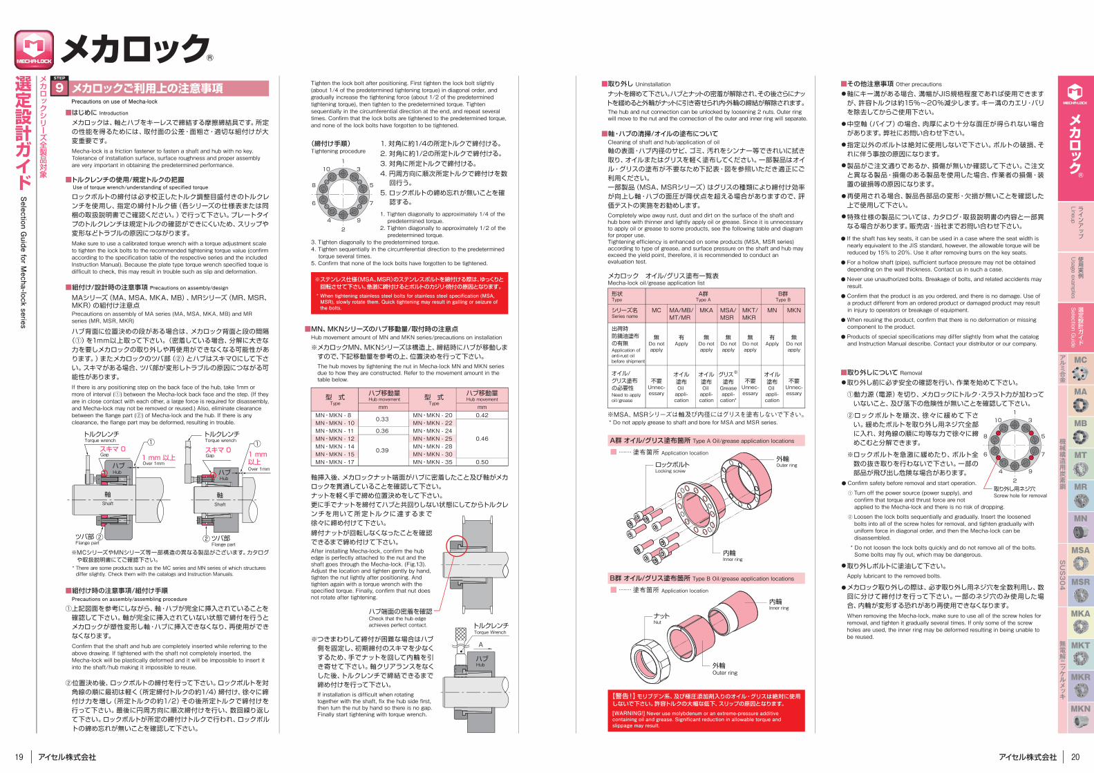
ハブ背面に位置決めの段がある場合は、メカロック背面と段の間隔(①)を1mm以上取って下さい。(密着している場合、分解に大きな力を要しメカロックの取り外しや再使用ができなくなる可能性があります。)またメカロックのツバ部(②)とハブはスキマ0にして下さい。スキマがある場合、ツバ部が変形しトラブルの原因につながる可能性があります。If there is any positioning step on the back face of the hub, take 1mm or more of interval (①) between the Mecha-lock back face and the step. (If they are in close contact with each other, a large force is required for disassembly, and Mecha-lock may not be removed or reused.) Also, eliminate clearance between the flange part (②) of Mecha-lock and the hub. If there is any clearance, the flange part may be deformed, resulting in trouble.
■組付け時の注意事項/組付け手順Precautions on assembly/assembling procedure
①上記図面を参考にしながら、軸・ハブが完全に挿入されていることを確認して下さい。軸が完全に挿入されていない状態で締付を行うとメカロックが塑性変形し軸・ハブに挿入できなくなり、再使用ができなくなります。Confirm that the shaft and hub are completely inserted while referring to the above drawing. If tightened with the shaft not completely inserted, the Mecha-lock will be plastically deformed and it will be impossible to insert it into the shaft/hub making it impossible to reuse.
②位置決め後、ロックボルトの締付を行って下さい。ロックボルトを対角線の順に最初は軽く(所定締付トルクの約1/4)締付け、徐々に締付け力を増し(所定トルクの約1/2)その後所定トルクで締付けを行って下さい。最後に円周方向に順次締付けを行い、数回繰り返して下さい。ロックボルトが所定の締付けトルクで行われ、ロックボルトの締め忘れが無いことを確認して下さい。
Tighten the lock bolt after positioning. First tighten the lock bolt slightly (about 1/4 of the predetermined tightening torque) in diagonal order, and gradually increase the tightening force (about 1/2 of the predetermined tightening torque), then tighten to the predetermined torque. Tighten sequentially in the circumferential direction at the end, and repeat several times. Confirm that the lock bolts are tightened to the predetermined torque, and none of the lock bolts have forgotten to be tightened.
■取り外しについて Removal取り外し前に必ず安全の確認を行い、作業を始めて下さい。
①動力源(電源)を切り、メカロックにトルク・スラスト力が加わっていないこと、及び落下の危険性が無いことを確認して下さい。
②ロックボルトを順次、徐々に緩めて下さい。緩めたボルトを取り外し用ネジ穴全部に入れ、対角線の順に均等な力で徐々に締めこむと分解できます。
※ロックボルトを急激に緩めたり、ボルト全数の抜き取りを行わないで下さい。一部の部品が飛び出し危険な場合があります。
● Confirm safety before removal and start operation.
① Turn off the power source (power supply), and confirm that torque and thrust force are not applied to the Mecha-lock and there is no risk of dropping.
② Loosen the lock bolts sequentially and gradually. Insert the loosened bolts into all of the screw holes for removal, and tighten gradually with uniform force in diagonal order, and then the Mecha-lock can be disassembled.
* Do not loosen the lock bolts quickly and do not remove all of the bolts. Some bolts may fly out, which may be dangerous.
取り外しボルトに塗油して下さい。Apply lubricant to the removed bolts.
メカロック取り外しの際は、必ず取り外し用ネジ穴を全数利用し、数回に分けて締付けを行って下さい。一部のネジ穴のみ使用した場合、内輪が変形する恐れがあり再使用できなくなります。When removing the Mecha-lock, make sure to use all of the screw holes for removal, and tighten it gradually several times. If only some of the screw holes are used, the inner ring may be deformed resulting in being unable to be reused.
■MN、MKNシリーズのハブ移動量/取付時の注意点Hub movement amount of MN and MKN series/precautions on installation
■取り外し Uninstallationナットを締めて下さい。ハブとナットの密着が解除され、その後さらにナットを緩めると外輪がナットに引き寄せられ内・外輪の締結が解除されます。The hub and nut connection can be unlocked by loosening 2 nuts. Outer ring will move to the nut and the connection of the outer and inner ring will separate.
■軸・ハブの清掃/オイルの塗布についてCleaning of shaft and hub/application of oil軸の表面・ハブ内径のサビ、ゴミ、汚れをシンナー等できれいに拭き取り、オイルまたはグリスを軽く塗布してください。一部製品はオイル・グリスの塗布が不要なため下記表・図を参照いただき適正にご利用ください。一部製品(MSA、MSRシリーズ)はグリスの種類により締付け効率が向上し軸・ハブの面圧が降伏点を超える場合がありますので、評価テストの実施をお勧めします。Completely wipe away rust, dust and dirt on the surface of the shaft and hub bore with thinner and lightly apply oil or grease. Since it is unnecessary to apply oil or grease to some products, see the following table and diagram for proper use.Tightening efficiency is enhanced on some products (MSA, MSR series) according to type of grease, and surface pressure on the shaft and hub may exceed the yield point, therefore, it is recommended to conduct an evaluation test.
■その他注意事項 Other precautions軸にキー溝がある場合、溝幅がJIS規格程度であれば使用できますが、許容トルクは約15%~20%減少します。キー溝のカエリ・バリを除去してからご使用下さい。
中空軸(パイプ)の場合、肉厚により十分な面圧が得られない場合があります。弊社にお問い合わせ下さい。
指定以外のボルトは絶対に使用しないで下さい。ボルトの破損、それに伴う事故の原因になります。
製品がご注文通りであるか、損傷が無いか確認して下さい。ご注文と異なる製品・損傷のある製品を使用した場合、作業者の損傷・装置の破損等の原因になります。
再使用される場合、製品各部品の変形・欠損が無いことを確認した上で使用して下さい。
特殊仕様の製品については、カタログ・取扱説明書の内容と一部異なる場合があります。販売店・当社までお問い合わせ下さい。
スキマ 0
ハブ1 mm 以上
軸
トルクレンチ
Shaft
Hub
Over 1mm
1 mm 以上Over 1mm
Torque wrenchトルクレンチTorque wrench
ツバ部Flange part
Gapスキマ 0Gap
ハブHub
軸Shaft
① ①
②ツバ部Flange part
②
(締付け手順)Tightening procedure
1
2
3
4
5
9
10
6 7
8
1
2
3
4
5
9
10
6 7
8
※ステンレス仕様(MSA、MSR)のステンレスボルトを締付ける際は、ゆっくりと回転させて下さい。急激に締付けるとボルトのカジリ・焼付の原因となります。* When tightening stainless steel bolts for stainless steel specification (MSA, MSR), slowly rotate them. Quick tightening may result in galling or seizure of the bolts.
【警告!】モリブデン系、及び極圧添加剤入りのオイル・グリスは絶対に使用しないで下さい。許容トルクの大幅な低下、スリップの原因となります。[WARNING!] Never use molybdenum or an extreme-pressure additive containing oil and grease. Significant reduction in allowable torque and slippage may result.
ハブHub
トルクレンチTorque Wrench
A
※メカロックMN、MKNシリーズは構造上、締結時にハブが移動しますので、下記移動量を参考の上、位置決めを行って下さい。 The hub moves by tightening the nut in Mecha-lock MN and MKN series due to how they are constructed. Refer to the movement amount in the table below.
※つきまわりして締付が困難な場合はハブ側を固定し、初期締付のスキマを少なくするため、手でナットを回して内輪を引き寄せて下さい。軸クリアランスをなくした後、トルクレンチで締結できるまで締め付けを行って下さい。If installation is difficult when rotating together with the shaft, fix the hub side first, then turn the nut by hand so there is no gap. Finally start tightening with torque wrench.
軸挿入後、メカロックナット端面がハブに密着したこと及び軸がメカロックを貫通していることを確認して下さい。ナットを軽く手で締め位置決めをして下さい。更に手でナットを締付てハブと共回りしない状態にしてからトルクレンチを用いて所定トルクに達するまで徐々に締め付けて下さい。締付ナットが回転しなくなったことを確認できるまで締め付けて下さい。After installing Mecha-lock, confirm the hub edge is perfectly attached to the nut and the shaft goes through the Mecha-lock. (Fig.13). Adjust the location and tighten gently by hand,tighten the nut lightly after positioning. And tighten again with a torque wrench with the specified torque. Finally, confirm that nut does not rotate after tightening.
ハブ端面の密着を確認Check that the hub edge achieves perfect contact.
型 式
形状Type
A群Type A
B群Type B
オイル/グリス塗布の必要性Need to apply oil/grease
出荷時防錆油塗布の有無Application of anti-rust oil before shipment
シリーズ名Series name
MC
無Do notapply
不要Unnec-essary
MN
有Apply
オイル塗布Oil appli-cation
MKA
無Do notapply
オイル塗布Oil appli-cation
MSA/MSR
無Do notapply
グリス※
塗布Greaseappli-cation*
MA/MB/MT/MR
有Apply
オイル塗布Oil appli-cation
MKT/MKR
無Do notapply
不要Unnec-essary
MKN
無Do notapply
不要Unnec-essary
mm mmMN・MKN - 8MN・MKN - 10MN・MKN - 11MN・MKN - 12MN・MKN - 14MN・MKN - 15MN・MKN - 17
MN・MKN - 20MN・MKN - 22MN・MKN - 24MN・MKN - 25MN・MKN - 28MN・MKN - 30MN・MKN - 35
0.33
0.36
0.39
0.42
0.46
0.50
ハブ移動量 ハブ移動量Type
型 式Type
Hub movement Hub movement
1. 対角に約1/4の所定トルクで締付ける。2. 対角に約1/2の所定トルクで締付ける。3. 対角に所定トルクで締付ける。4. 円周方向に順次所定トルクで締付けを数回行う。
5. ロックボルトの締め忘れが無いことを確認する。
1. Tighten diagonally to approximately 1/4 of the predetermined torque.
2. Tighten diagonally to approximately 1/2 of the predetermined torque.
3. Tighten diagonally to the predetermined torque.4. Tighten sequentially in the circumferential direction to the predetermined torque several times.
5. Confirm that none of the lock bolts have forgotten to be tightened.
外輪Outer ringロックボルト
Locking screw
内輪Inner ring
ナットNut
外輪Outer ring
内輪Inner ring
メカロック オイル/グリス塗布一覧表Mecha-lock oil/grease application list
A群 オイル/グリス塗布箇所 Type A Oil/grease application locations
■ …… 塗布箇所 Application location
B群 オイル/グリス塗布箇所 Type B Oil/grease application locations
■ …… 塗布箇所 Application location
※MSA、MSRシリーズは軸及び内径にはグリスを塗布しないで下さい。* Do not apply grease to shaft and bore for MSA and MSR series.
●
●
●
●
●
●
●
●
●
● If the shaft has key seats, it can be used in a case where the seat width is nearly equivalent to the JIS standard, however, the allowable torque will be reduced by 15% to 20%. Use it after removing burrs on the key seats.
● For a hollow shaft (pipe), sufficient surface pressure may not be obtained depending on the wall thickness. Contact us in such a case.
● Never use unauthorized bolts. Breakage of bolts, and related accidents may result.
● Confirm that the product is as you ordered, and there is no damage. Use of a product different from an ordered product or damaged product may result in injury to operators or breakage of equipment.
● When reusing the product, confirm that there is no deformation or missing component to the product.
● Products of special specifications may differ slightly from what the catalog and Instruction Manual describe. Contact your distributor or our company.
取り外し用ネジ穴Screw hole for removal
STEP
9 メカロックご利用上の注意事項Precautions on use of Mecha-lock
■はじめに Introductionメカロックは、軸とハブをキーレスで締結する摩擦締結具です。所定の性能を得るためには、取付面の公差・面粗さ・適切な組付けが大変重要です。Mecha-lock is a friction fastener to fasten a shaft and hub with no key. Tolerance of installation surface, surface roughness and proper assembly are very important in obtaining the predetermined performance.


![BEVEL GEAR BOX - makishinko.co.jp · ベ ベ ル ギ ヤ ボ ッ ク ス bevel gear box {jt ]d Ý)d./+d/4 /4,3,05 3807 nk wyu 331](https://img.pdfslide.tips/doc/110x75/5b8e59a409d3f2187e8d7657/bevel-gear-box-bevel-gear-box-jt-d-ydd4.jpg)


![ー グ ル メ 大 集 合! ボ ダ ー ー ダ う ぇ ボ い - …ボ ー ダ ー グ ル メ 大 集 合!ボ ー ダ ー う ぇ い!9 9 / 2 0 [Fri] ~ 1 1 / [ S a t] 投稿方法](https://img.pdfslide.tips/doc/110x75/5e50c245a1b91a41e63e4015/f-f-f-e-i-foe-f-f-f-f-foe-foe-f-f.jpg)


![メールmedia.kddi.com/app/publish/torisetsu/pdf/infobar_c01_to...94 shx12_08.fm [94/132] メ-ル Eメール(~@ezweb.ne.jp)はEメールに対応した携帯電話やパソコン](https://img.pdfslide.tips/doc/110x75/60826b84436db87f01163678/fffmediakddicomapppublishtorisetsupdfinfobarc01to-94-shx1208fm.jpg)