Embed Size (px)
Citation preview

DICHIARAZIONE DI PRESTAZIONI
ai sensi dell'Allegato III del regolamento (EU) n. 305/2011 (Regolamento sui Prodotti da Costruzione)
Benda antifuoco Hilti CFS-B
N. Hilti CFS “1121-CPD-J0010”
1. Codice di identificazione unico del prodotto-tipo:
Benda antifuoco Hilti CFS-B
2. Usi previsti:
Prodotto antifuoco e sigillante per tamponamenti, ved. ETA-10/0212 (06.05.2014)
Aperture per tubi Tubi in metallo con isolamento combustibile
Il campo di applicazione deve essere conforme al contenuto del relativo ETA-10/0212
3. Fabbricante:
HILTI Corporation, Feldkircherstrasse 100, 9494 Schaan, Principato del Liechtenstein
4. Sistemi di VVCP:
Sistema 1
5. Documento per la valutazione europea:
ETAG n. 026-1 ed ETAG n. 026-2 Valutazione tecnica europea:
ETA-10/0212 (06.05.2014) Organismo di valutazione tecnica:
Warrington Certification Ltd
Organismi notificati:
Warrington Certification Ltd, No. 1121 6. Prestazioni dichiarate:
Caratteristiche essenziali Prestazioni dichiarate / specifica tecnica armonizzata
Reazione al fuoco Classe E secondo EN 13501-1
Resistenza al fuoco Prestazioni per resistenza al fuoco e campo di applicazione conformemente alla norma EN 13501-2. Vedere allegato
Sostanze pericolose Vedere allegato
Durata e servizio Z2, conformemente a ETAG 026-2, report tecnico EOTA - TR024
Altro Non applicabile / nessuna prestazione determinata
La prestazione del prodotto sopra identificato è conforme all'insieme delle prestazioni dichiarate. La presente dichiarazione di responsabilità viene emessa, in conformità al regolamento (UE) n. 305/2011, sotto la sola responsabilità del fabbricante sopra identificato. Firmato a nome e per conto del fabbricante da:
Jingyan Zhou Product Manager Business Unit Fire Protection Hilti Corporation
Schaan, 12 April 2018 DoP_it_03-01_000000001491_Hilti CFS-B_”1121-CPD-J0010”
IT
Martin Althof Head of Quality Business Unit Fire Protection Hilti Corporation
3.5 Dangerous substances
The applicant is required to submit a written declaration stating whether or not the fire stopping and fire sealing product contains dangerous substances according to European and national regulations, when and where relevant in the Member States of destination, and shall list these substances. Hilti Corporation declare that product Hilti Firestop Bandage CFS-B is in compliance with Council Directive 76/769/EEC of 27th July 1976 on the approximation of the laws, regulations and administrative provisions of the Member States relating to restrictions on the marketing and use of certain dangerous substances and preparations (incl. all amendments and adaptations). Confirmation has further been declared that all dangerous chemical substances ≥ 1.0 % w/w as well as all toxic, carcinogenic, toxic for reproduction and mutagenic chemical substances ≥ 0.1 % w/w (Status: 29. adaption –2004/73/EG – of the EU directive 67/548/EEC ‐ classification, packaging and labelling of dangerous substances)
are stated in the Hilti Firestop Bandage CFS-B material safety data sheets (according to 91/155/EEC including amendments) and have been considered for the classification of the products according to the directive1999/45/EG (classification of preparations, including amendments). All dangerous chemical substances are below the classification limits of 67/548/EEC.
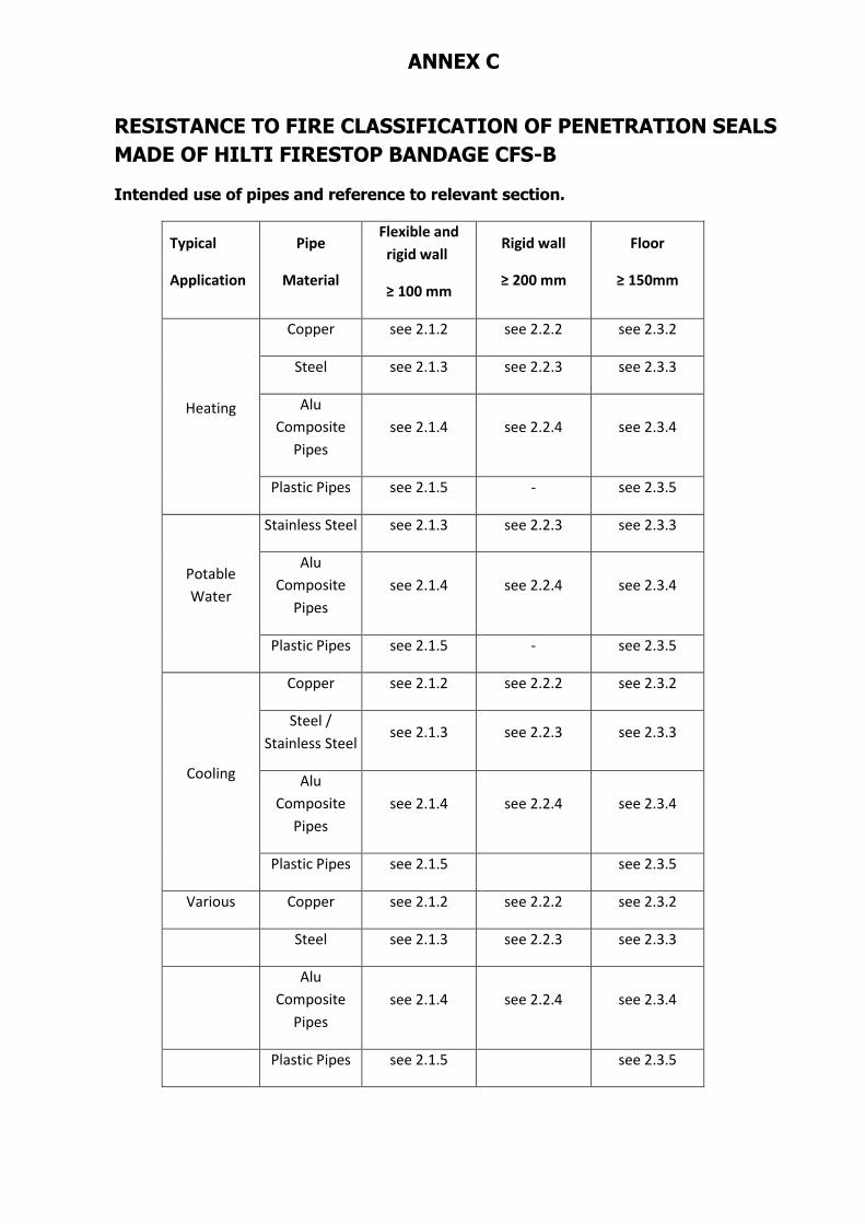
ANNEX C
RESISTANCE TO FIRE CLASSIFICATION OF PENETRATION SEALS
MADE OF HILTI FIRESTOP BANDAGE CFS-B
Intended use of pipes and reference to relevant section.
Typical
Application
Pipe
Material
Flexible and
rigid wall
≥ 100 mm
Rigid wall
≥ 200 mm
Floor
≥ 150mm
Heating
Copper see 2.1.2 see 2.2.2 see 2.3.2
Steel see 2.1.3 see 2.2.3 see 2.3.3
Alu
Composite
Pipes
see 2.1.4 see 2.2.4 see 2.3.4
Plastic Pipes see 2.1.5 - see 2.3.5
Potable
Water
Stainless Steel see 2.1.3 see 2.2.3 see 2.3.3
Alu
Composite
Pipes
see 2.1.4 see 2.2.4 see 2.3.4
Plastic Pipes see 2.1.5 - see 2.3.5
Cooling
Copper see 2.1.2 see 2.2.2 see 2.3.2
Steel /
Stainless Steel see 2.1.3 see 2.2.3 see 2.3.3
Alu
Composite
Pipes
see 2.1.4 see 2.2.4 see 2.3.4
Plastic Pipes see 2.1.5 see 2.3.5
Various Copper see 2.1.2 see 2.2.2 see 2.3.2
Steel see 2.1.3 see 2.2.3 see 2.3.3
Alu
Composite
Pipes
see 2.1.4 see 2.2.4 see 2.3.4
Plastic Pipes see 2.1.5 see 2.3.5
1 General Information Hilti Firestop Bandage CFS-B
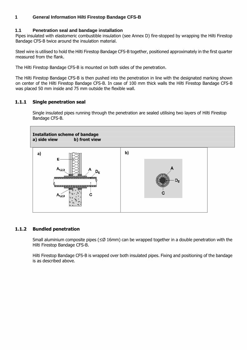
1.1 Penetration seal and bandage installation
Pipes insulated with elastomeric combustible insulation (see Annex D) fire-stopped by wrapping the Hilti Firestop Bandage CFS-B twice around the insulation material. Steel wire is utilised to hold the Hilti Firestop Bandage CFS-B together, positioned approximately in the first quarter measured from the flank. The Hilti Firestop Bandage CFS-B is mounted on both sides of the penetration. The Hilti Firestop Bandage CFS-B is then pushed into the penetration in line with the designated marking shown on center of the Hilti Firestop Bandage CFS-B. In case of 100 mm thick walls the Hilti Firestop Bandage CFS-B was placed 50 mm inside and 75 mm outside the flexible wall.
1.1.1 Single penetration seal Single insulated pipes running through the penetration are sealed utilising two layers of Hilti Firestop Bandage CFS-B.
Installation scheme of bandage
a) side view b) front view
1.1.2 Bundled penetration Small aluminium composite pipes (≤Ø 16mm) can be wrapped together in a double penetration with the Hilti Firestop Bandage CFS-B. Hilti Firestop Bandage CFS-B is wrapped over both insulated pipes. Fixing and positioning of the bandage is as described above.
a) b)
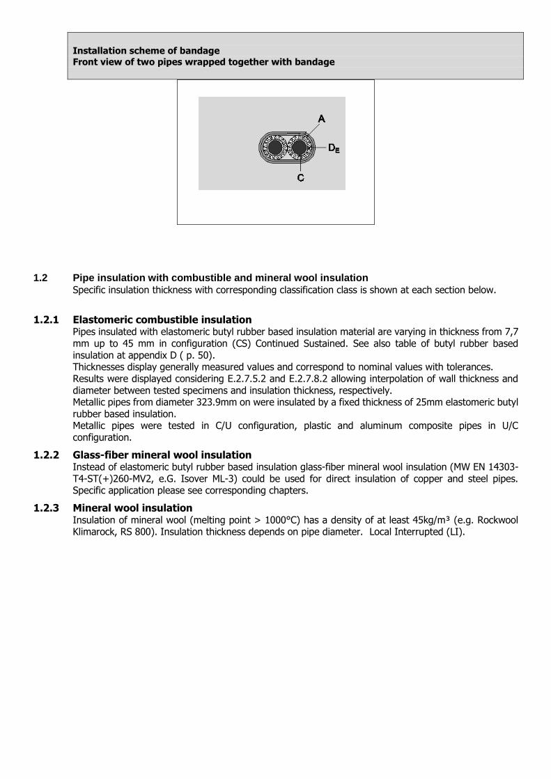
Installation scheme of bandage
Front view of two pipes wrapped together with bandage
1.2 Pipe insulation with combustible and mineral wool insulation
Specific insulation thickness with corresponding classification class is shown at each section below.
1.2.1 Elastomeric combustible insulation Pipes insulated with elastomeric butyl rubber based insulation material are varying in thickness from 7,7 mm up to 45 mm in configuration (CS) Continued Sustained. See also table of butyl rubber based insulation at appendix D ( p. 50). Thicknesses display generally measured values and correspond to nominal values with tolerances. Results were displayed considering E.2.7.5.2 and E.2.7.8.2 allowing interpolation of wall thickness and diameter between tested specimens and insulation thickness, respectively. Metallic pipes from diameter 323.9mm on were insulated by a fixed thickness of 25mm elastomeric butyl rubber based insulation. Metallic pipes were tested in C/U configuration, plastic and aluminum composite pipes in U/C configuration.
1.2.2 Glass-fiber mineral wool insulation Instead of elastomeric butyl rubber based insulation glass-fiber mineral wool insulation (MW EN 14303-T4-ST(+)260-MV2, e.G. Isover ML-3) could be used for direct insulation of copper and steel pipes. Specific application please see corresponding chapters.
1.2.3 Mineral wool insulation Insulation of mineral wool (melting point > 1000°C) has a density of at least 45kg/m³ (e.g. Rockwool Klimarock, RS 800). Insulation thickness depends on pipe diameter. Local Interrupted (LI).
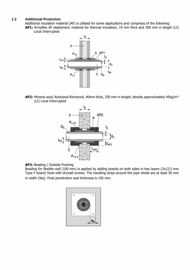
1.3 Additional Protection
Additional insulation material (AP) is utilised for some applications and comprises of the following: AP1: Armaflex AF elastomeric material for thermal insulation, 19 mm thick and 300 mm in length (LI)
Local Interrupted
AP2: Mineral wool, Rockwool Klimarock, 40mm thick, 250 mm in length; density approximately 45kg/m³ (LI) Local Interrupted
AP3: Beading / Outside Framing Beading for flexible wall (100 mm) is applied by adding boards on both sides in two layers (2x12,5 mm Type F board) fixed with drywall screws. The resulting strips around the pipe whole are at least 50 mm
in width (WB). Final penetration seal thickness is 150 mm.
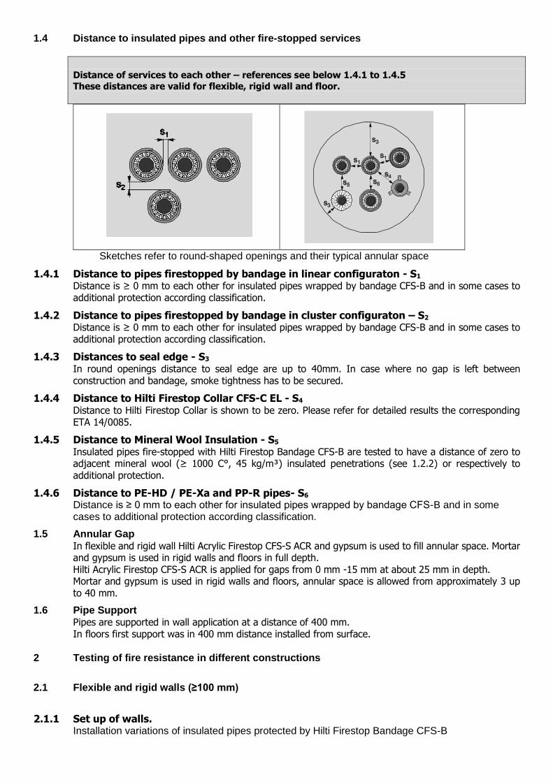
1.4 Distance to insulated pipes and other fire-stopped services
Distance of services to each other – references see below 1.4.1 to 1.4.5
These distances are valid for flexible, rigid wall and floor.
Sketches refer to round-shaped openings and their typical annular space
1.4.1 Distance to pipes firestopped by bandage in linear configuraton - S1 Distance is ≥ 0 mm to each other for insulated pipes wrapped by bandage CFS-B and in some cases to additional protection according classification.
1.4.2 Distance to pipes firestopped by bandage in cluster configuraton – S2 Distance is ≥ 0 mm to each other for insulated pipes wrapped by bandage CFS-B and in some cases to additional protection according classification.
1.4.3 Distances to seal edge - S3 In round openings distance to seal edge are up to 40mm. In case where no gap is left between construction and bandage, smoke tightness has to be secured.
1.4.4 Distance to Hilti Firestop Collar CFS-C EL - S4 Distance to Hilti Firestop Collar is shown to be zero. Please refer for detailed results the corresponding ETA 14/0085.
1.4.5 Distance to Mineral Wool Insulation - S5 Insulated pipes fire-stopped with Hilti Firestop Bandage CFS-B are tested to have a distance of zero to adjacent mineral wool (≥ 1000 C°, 45 kg/m³) insulated penetrations (see 1.2.2) or respectively to additional protection.
1.4.6 Distance to PE-HD / PE-Xa and PP-R pipes- S6 Distance is ≥ 0 mm to each other for insulated pipes wrapped by bandage CFS-B and in some cases to additional protection according classification.
1.5 Annular Gap
In flexible and rigid wall Hilti Acrylic Firestop CFS-S ACR and gypsum is used to fill annular space. Mortar and gypsum is used in rigid walls and floors in full depth. Hilti Acrylic Firestop CFS-S ACR is applied for gaps from 0 mm -15 mm at about 25 mm in depth. Mortar and gypsum is used in rigid walls and floors, annular space is allowed from approximately 3 up to 40 mm.
1.6 Pipe Support
Pipes are supported in wall application at a distance of 400 mm. In floors first support was in 400 mm distance installed from surface.
2 Testing of fire resistance in different constructions
2.1 Flexible and rigid walls (≥100 mm)
2.1.1 Set up of walls. Installation variations of insulated pipes protected by Hilti Firestop Bandage CFS-B
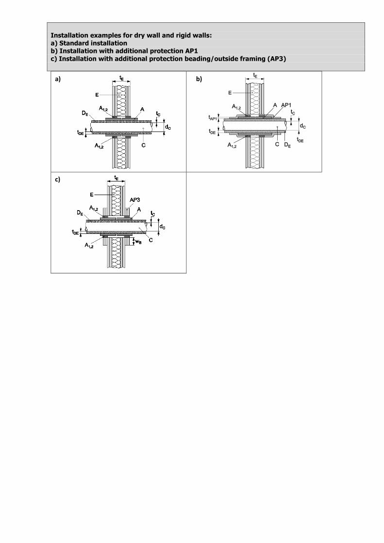
Installation examples for dry wall and rigid walls:
a) Standard installation b) Installation with additional protection AP1
c) Installation with additional protection beading/outside framing (AP3)
a) b)
c)
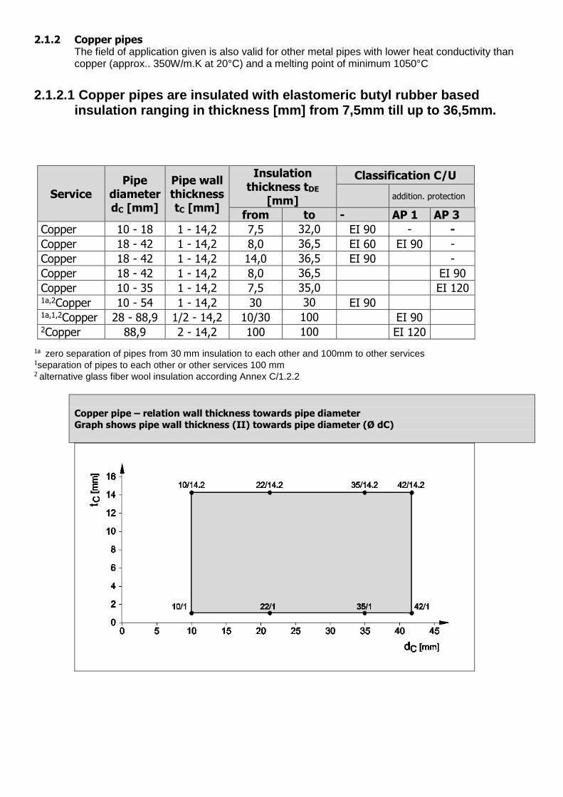
2.1.2 Copper pipes The field of application given is also valid for other metal pipes with lower heat conductivity than copper (approx.. 350W/m.K at 20°C) and a melting point of minimum 1050°C
2.1.2.1 Copper pipes are insulated with elastomeric butyl rubber based insulation ranging in thickness [mm] from 7,5mm till up to 36,5mm.
Service Pipe
diameter dC [mm]
Pipe wall thickness tC [mm]
Insulation thickness tDE
[mm]
Classification C/U
addition. protection
from to - AP 1 AP 3
Copper 10 - 18 1 - 14,2 7,5 32,0 EI 90 - -
Copper 18 - 42 1 - 14,2 8,0 36,5 EI 60 EI 90 -
Copper 18 - 42 1 - 14,2 14,0 36,5 EI 90 -
Copper 18 - 42 1 - 14,2 8,0 36,5 EI 90
Copper 10 - 35 1 - 14,2 7,5 35,0 EI 120 1a,2Copper 10 - 54 1 - 14,2 30 30 EI 90 1a,1,2Copper 28 - 88,9 1/2 - 14,2 10/30 100 EI 90 2Copper 88,9 2 - 14,2 100 100 EI 120
1a zero separation of pipes from 30 mm insulation to each other and 100mm to other services
1separation of pipes to each other or other services 100 mm 2 alternative glass fiber wool insulation according Annex C/1.2.2
Copper pipe – relation wall thickness towards pipe diameter
Graph shows pipe wall thickness (II) towards pipe diameter (Ø dC)
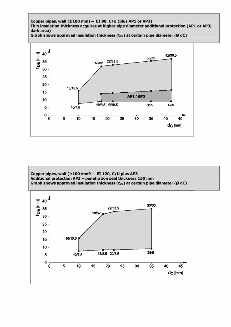
Copper pipes, wall (≥100 mm) – EI 90, C/U (plus AP1 or AP3)
Thin insulation thickness acquires at higher pipe diameter additional protection (AP1 or AP3; dark area)
Graph shows approved insulation thickness (tDE) at certain pipe diameter (Ø dC)
Copper pipes, wall (≥100 mm9 – EI 120, C/U plus AP3 Additional protection AP3 – penetration seal thickness 150 mm
Graph shows approved insulation thickness (tDE) at certain pipe diameter (Ø dC)
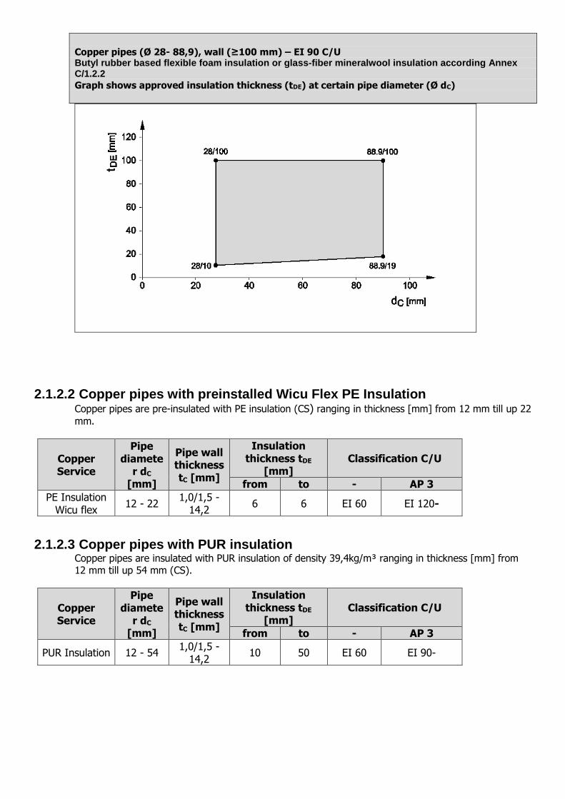
Copper pipes (Ø 28- 88,9), wall (≥100 mm) – EI 90 C/U Butyl rubber based flexible foam insulation or glass-fiber mineralwool insulation according Annex C/1.2.2
Graph shows approved insulation thickness (tDE) at certain pipe diameter (Ø dC)
2.1.2.2 Copper pipes with preinstalled Wicu Flex PE Insulation Copper pipes are pre-insulated with PE insulation (CS) ranging in thickness [mm] from 12 mm till up 22
mm.
Copper Service
Pipe diamete
r dC [mm]
Pipe wall thickness tC [mm]
Insulation thickness tDE
[mm] Classification C/U
from to - AP 3
PE Insulation Wicu flex 12 - 22
1,0/1,5 - 14,2
6 6 EI 60 EI 120-
2.1.2.3 Copper pipes with PUR insulation Copper pipes are insulated with PUR insulation of density 39,4kg/m³ ranging in thickness [mm] from 12 mm till up 54 mm (CS).
Copper Service
Pipe diamete
r dC [mm]
Pipe wall thickness tC [mm]
Insulation thickness tDE
[mm] Classification C/U
from to - AP 3
PUR Insulation 12 - 54 1,0/1,5 -
14,2 10 50 EI 60 EI 90-
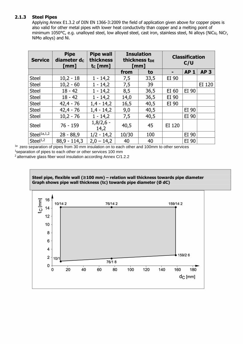
2.1.3 Steel Pipes Applying Annex E1.3.2 of DIN EN 1366-3:2009 the field of application given above for copper pipes is also valid for other metal pipes with lower heat conductivity than copper and a melting point of minimum 1050°C, e.g. unalloyed steel, low alloyed steel, cast iron, stainless steel, Ni alloys (NiCu, NiCr, NiMo alloys) and Ni.
Service Pipe
diameter dC [mm]
Pipe wall thickness tC [mm]
Insulation thickness tDE
[mm]
Classification C/U
from to - AP 1 AP 3
Steel 10,2 - 18 1 - 14,2 7,5 33,5 EI 90
Steel 10,2 - 60 1 - 14,2 7,5 39 EI 120
Steel 18 - 42 1 - 14,2 8,5 36,5 EI 60 EI 90
Steel 18 - 42 1 - 14,2 14,0 36,5 EI 90
Steel 42,4 - 76 1,4 - 14,2 16,5 40,5 EI 90
Steel 42,4 - 76 1,4 - 14,2 9,0 40,5 EI 90
Steel 10,2 - 76 1 - 14,2 7,5 40,5 EI 90
Steel 76 - 159 1,8/2,6 -
14,2 40,5 45 EI 120
Steel1a,1,2 28 - 88,9 1/2 - 14,2 10/30 100 EI 90
Steel1,2 88,9 - 114,3 2,0 – 14,2 40 40 EI 90 1a zero separation of pipes from 30 mm insulation on to each other and 100mm to other services
1separation of pipes to each other or other services 100 mm 2 alternative glass fiber wool insulation according Annex C/1.2.2
Steel pipe, flexible wall (≥100 mm) – relation wall thickness towards pipe diameter Graph shows pipe wall thickness (tc) towards pipe diameter (Ø dC)
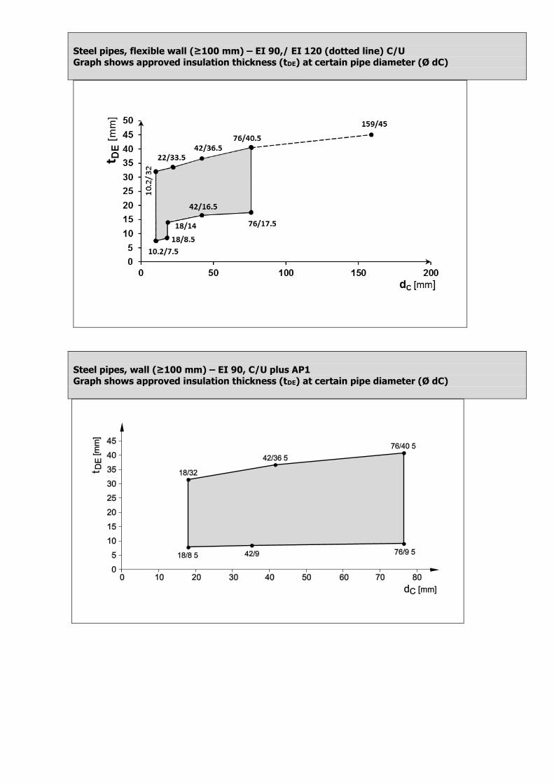
Steel pipes, flexible wall (≥100 mm) – EI 90,/ EI 120 (dotted line) C/U
Graph shows approved insulation thickness (tDE) at certain pipe diameter (Ø dC)
Steel pipes, wall (≥100 mm) – EI 90, C/U plus AP1
Graph shows approved insulation thickness (tDE) at certain pipe diameter (Ø dC)
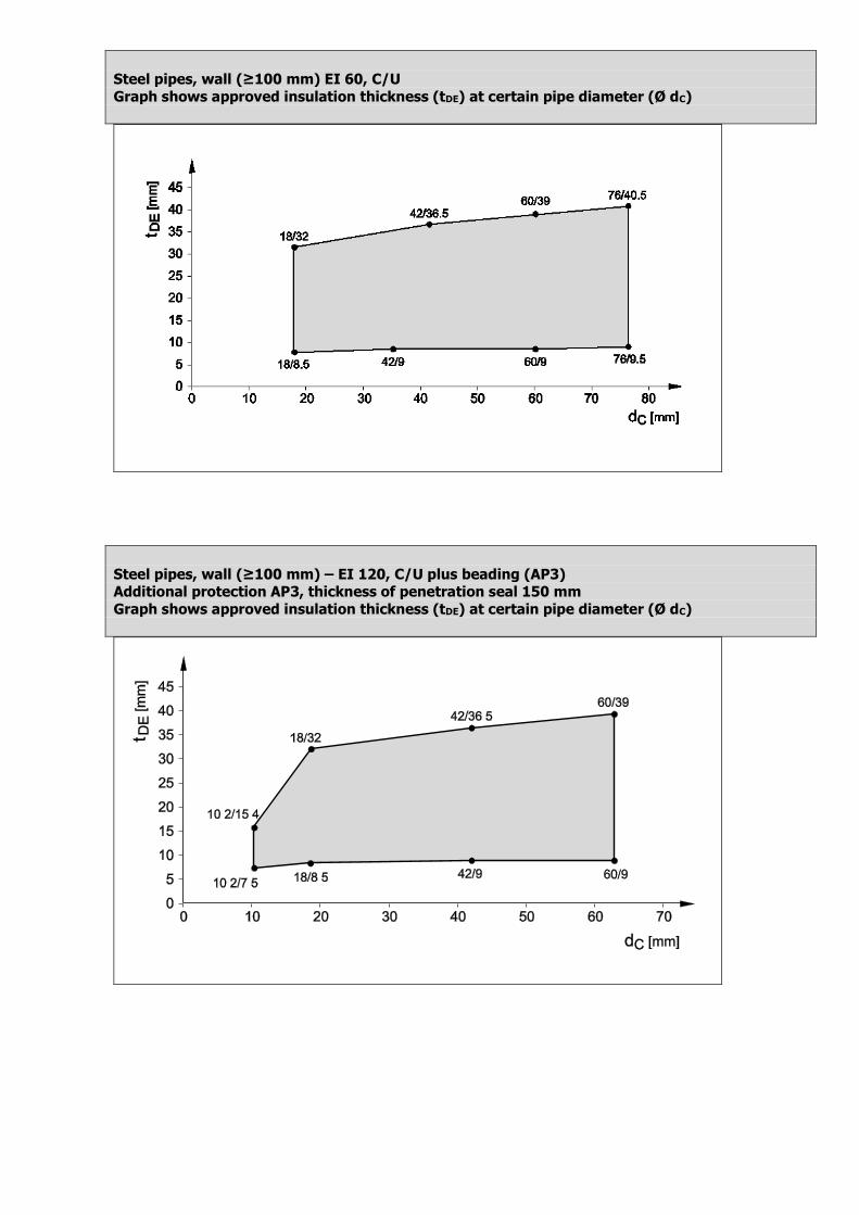
Steel pipes, wall (≥100 mm) EI 60, C/U
Graph shows approved insulation thickness (tDE) at certain pipe diameter (Ø dC)
Steel pipes, wall (≥100 mm) – EI 120, C/U plus beading (AP3) Additional protection AP3, thickness of penetration seal 150 mm
Graph shows approved insulation thickness (tDE) at certain pipe diameter (Ø dC)
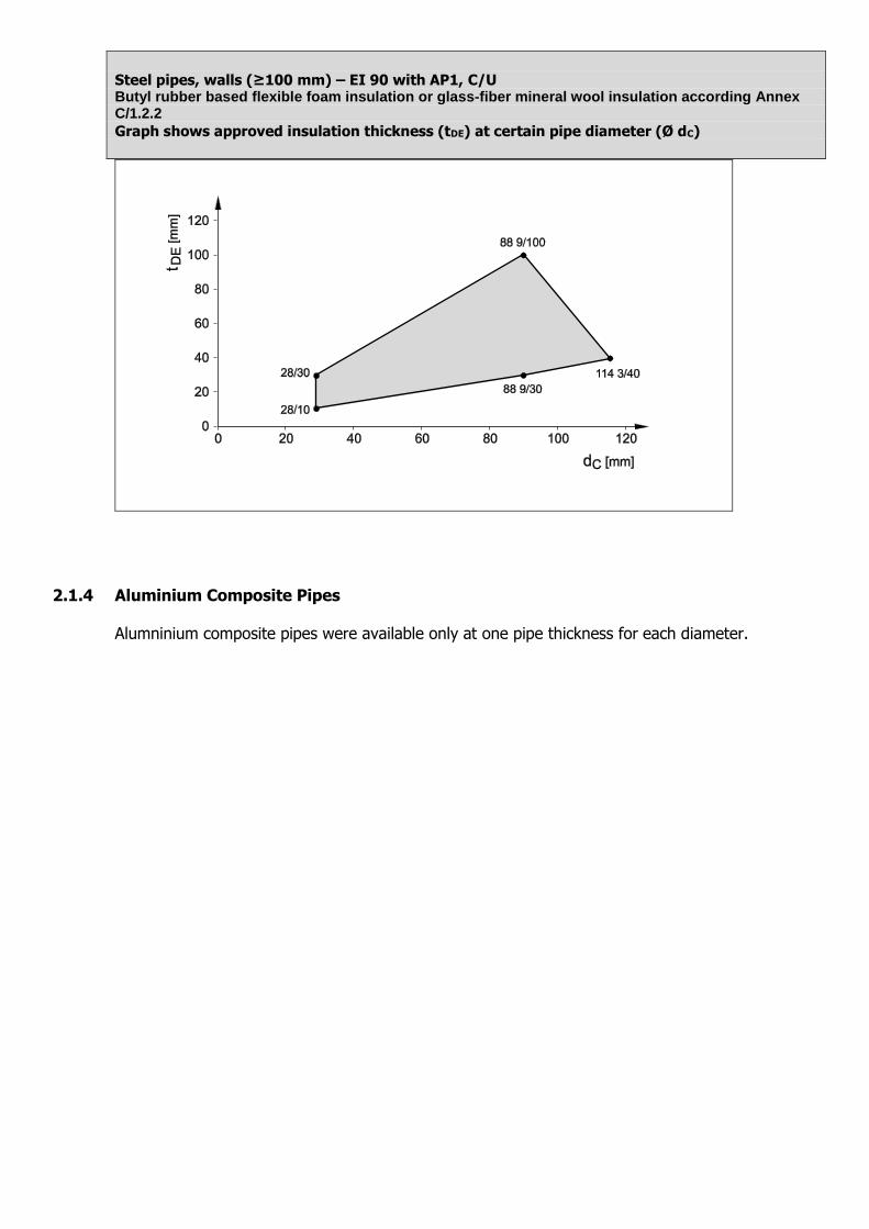
Steel pipes, walls (≥100 mm) – EI 90 with AP1, C/U Butyl rubber based flexible foam insulation or glass-fiber mineral wool insulation according Annex C/1.2.2
Graph shows approved insulation thickness (tDE) at certain pipe diameter (Ø dC)
2.1.4 Aluminium Composite Pipes
Alumninium composite pipes were available only at one pipe thickness for each diameter.
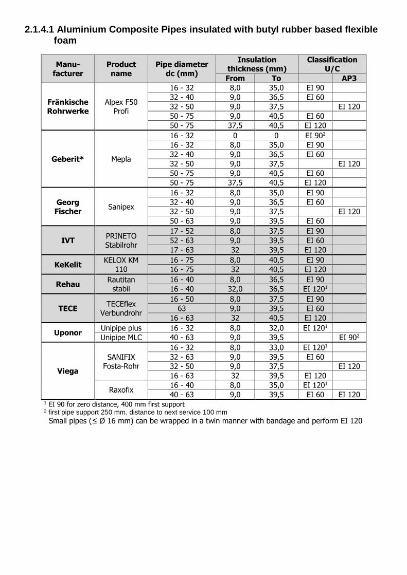
2.1.4.1 Aluminium Composite Pipes insulated with butyl rubber based flexible foam
Manu-facturer
Product name
Pipe diameter dc (mm)
Insulation thickness (mm)
Classification U/C
From To AP3
Fränkische Rohrwerke
Alpex F50 Profi
16 - 32 8,0 35,0 EI 90
32 - 40 9,0 36,5 EI 60
32 - 50 9,0 37,5 EI 120
50 - 75 9,0 40,5 EI 60
50 - 75 37,5 40,5 EI 120
Geberit* Mepla
16 - 32 0 0 EI 902
16 - 32 8,0 35,0 EI 90
32 - 40 9,0 36,5 EI 60
32 - 50 9,0 37,5 EI 120
50 - 75 9,0 40,5 EI 60
50 - 75 37,5 40,5 EI 120
Georg Fischer
Sanipex
16 - 32 8,0 35,0 EI 90
32 - 40 9,0 36,5 EI 60
32 - 50 9,0 37,5 EI 120
50 - 63 9,0 39,5 EI 60
IVT PRINETO Stabilrohr
17 - 52 8,0 37,5 EI 90
52 - 63 9,0 39,5 EI 60
17 - 63 32 39,5 EI 120
KeKelit KELOX KM
110
16 - 75 8,0 40,5 EI 90
16 - 75 32 40,5 EI 120
Rehau Rautitan
stabil
16 - 40 8,0 36,5 EI 90
16 - 40 32,0 36,5 EI 1201
TECE TECEflex
Verbundrohr
16 - 50 8,0 37,5 EI 90
63 9,0 39,5 EI 60
16 - 63 32 40,5 EI 120
Uponor Unipipe plus 16 - 32 8,0 32,0 EI 1201
Unipipe MLC 40 - 63 9,0 39,5 EI 902
Viega
SANIFIX Fosta-Rohr
16 - 32 8,0 33,0 EI 1201
32 - 63 9,0 39,5 EI 60
32 - 50 9,0 37,5 EI 120
16 - 63 32 39,5 EI 120
Raxofix 16 - 40 8,0 35,0 EI 1201
40 - 63 9,0 39,5 EI 60 EI 120
1 EI 90 for zero distance, 400 mm first support 2 first pipe support 250 mm, distance to next service 100 mm
Small pipes (≤ Ø 16 mm) can be wrapped in a twin manner with bandage and perform EI 120

Graph shows results simplified, for all details see table above.
Aluminium Composite Pipes, wall (≥ 100 mm) - EI 60, U/C
All specimens listed
Graph shows approved insulation thickness (tDE) at certain pipe diameter (Ø dC)
Group 1 of composite pipes (grey shaded) – Brand: Kekelit (Kelox), IVT (Prineto Stabil Rohr), Rehau (≤40 mm)(Rautitan stabil), TECEflex
Aluminium Composite Pipes, wall (≥ 100 mm) - EI 90, U/C All pipes of group 1
Graph shows approved insulation thickness (tDE) at certain pipe diameter (Ø dC)
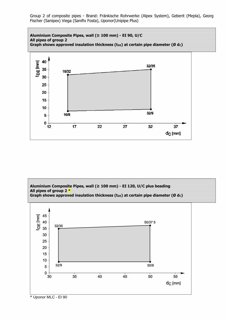
Group 2 of composite pipes - Brand: Fränkische Rohrwerke (Alpex System), Geberit (Mepla), Georg Fischer (Sanipex) Viega (Sanifix Fosta), Uponor(Unipipe Plus)
Aluminium Composite Pipes, wall (≥ 100 mm) - EI 90, U/C
All pipes of group 2 Graph shows approved insulation thickness (tDE) at certain pipe diameter (Ø dC)
Aluminium Composite Pipes, wall (≥ 100 mm) - EI 120, U/C plus beading
All pipes of group 2 * Graph shows approved insulation thickness (tDE) at certain pipe diameter (Ø dC)
* Uponor MLC - EI 90
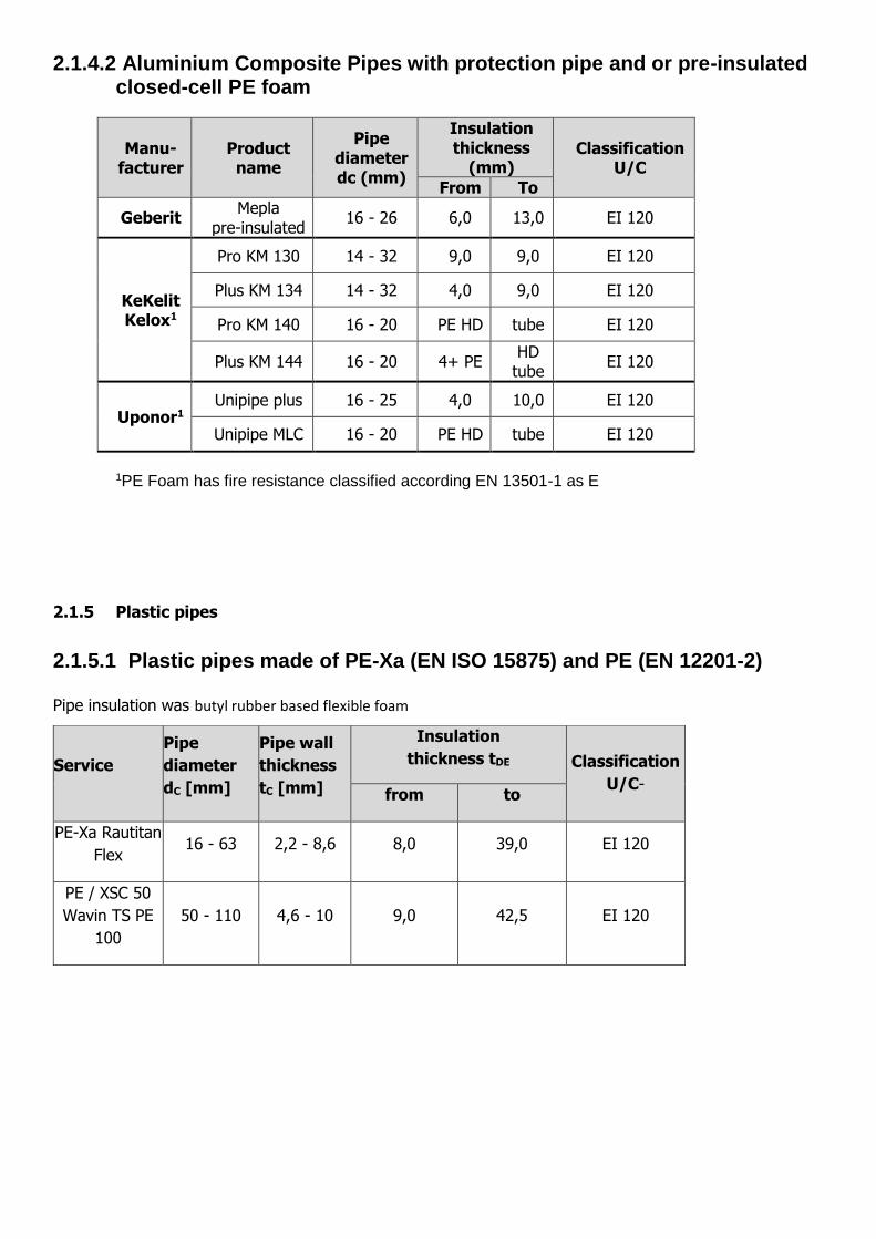
2.1.4.2 Aluminium Composite Pipes with protection pipe and or pre-insulated closed-cell PE foam
Manu-facturer
Product name
Pipe diameter dc (mm)
Insulation thickness
(mm) Classification
U/C
From To
Geberit Mepla
pre-insulated 16 - 26 6,0 13,0 EI 120
KeKelit Kelox1
Pro KM 130 14 - 32 9,0 9,0 EI 120
Plus KM 134 14 - 32 4,0 9,0 EI 120
Pro KM 140 16 - 20 PE HD tube EI 120
Plus KM 144 16 - 20 4+ PE HD
tube EI 120
Uponor1 Unipipe plus 16 - 25 4,0 10,0 EI 120
Unipipe MLC 16 - 20 PE HD tube EI 120
1PE Foam has fire resistance classified according EN 13501-1 as E
2.1.5 Plastic pipes
2.1.5.1 Plastic pipes made of PE-Xa (EN ISO 15875) and PE (EN 12201-2)
Pipe insulation was butyl rubber based flexible foam
Service
Pipe
diameter
dC [mm]
Pipe wall
thickness
tC [mm]
Insulation
thickness tDE
[mm]
Classification
U/C- from to
PE-Xa Rautitan
Flex 16 - 63 2,2 - 8,6 8,0 39,0 EI 120
PE / XSC 50
Wavin TS PE
100
50 - 110 4,6 - 10 9,0 42,5 EI 120

Plastic pipes PE-X according EN ISO 15875, wall (≥ 100 mm) - EI 120, U/C
Graph shows approved insulation thickness (tDE) at certain pipe diameter (Ø dC)
Plastic pipes PE-HD according EN 12201-2, wall (≥ 100 mm) - EI 120, U/C
Graph shows approved insulation thickness (tDE) at certain pipe diameter (Ø dC)

2.1.5.2 Plastic pipes made of PP-R (EN 15874 / DIN 8077/78 / ISO 21003) Plastic pipes are insulated with butyl rubber based flexible foam
Manu-facturer
Product name Pipe diameter dc (mm)
Wall thickness (mm)
Insulation thickness (mm)
Classification U/C
From To
Aquaterm Green1,3 20 - 110 1,9 - 10 8,0 40,5 EI 120*
Blue1,3 20 - 110 1,9 - 10 8,0 40,5 EI 120*
Poloplast Polo-Polymutan
ML52 20 - 75 2,8 - 10,3 8,5 40,5 EI 120*
Polo-Polymutan3 20 - 75 1,9 - 6,8 8,0 40,5 EI 90
Polo-Tersia3 20 - 75 1,9 - 12,5 8,0 40,5 EI 90
Kekelit Ketrix
Cryolen Polyolefinblend1 20 - 75 1,9 - 6,8 8,0 40,5 EI 90
* for zero distance and / or 400 mm first pipe support classification is EI 90 U/C 1 according EN 15874 2 according ISO 21003
3 according DIN 8077/78
2.2 Rigid Wall (≥ 200 mm)
2.2.1 Set-up of rigid wall
The wall must have a minimum thickness of 200 mm and comprise of concrete, aerated concrete or masonry, with a minimum density of 550 kg/m3
Installation variants of insulated pipes protected by Hilti Firestop Bandage CFS-B
Installation examples: a) Standard installation
b) Installation with additional protection AP2
a) b)
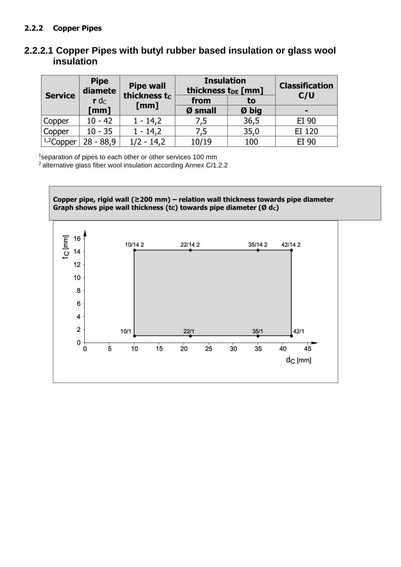
2.2.2 Copper Pipes
2.2.2.1 Copper Pipes with butyl rubber based insulation or glass wool insulation
Service
Pipe diamete
r dC [mm]
Pipe wall thickness tC
[mm]
Insulation thickness tDE [mm]
Classification C/U
from to
Ø small Ø big -
Copper 10 - 42 1 - 14,2 7,5 36,5 EI 90
Copper 10 - 35 1 - 14,2 7,5 35,0 EI 120 1,2Copper 28 - 88,9 1/2 - 14,2 10/19 100 EI 90
1separation of pipes to each other or other services 100 mm 2 alternative glass fiber wool insulation according Annex C/1.2.2
Copper pipe, rigid wall (≥200 mm) – relation wall thickness towards pipe diameter Graph shows pipe wall thickness (tc) towards pipe diameter (Ø dC)
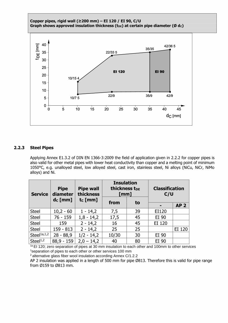
Copper pipes, rigid wall (≥200 mm) – EI 120 / EI 90, C/U
Graph shows approved insulation thickness (tDE) at certain pipe diameter (Ø dC)
2.2.3 Steel Pipes Applying Annex E1.3.2 of DIN EN 1366-3:2009 the field of application given in 2.2.2 for copper pipes is also valid for other metal pipes with lower heat conductivity than copper and a melting point of minimum 1050°C, e.g. unalloyed steel, low alloyed steel, cast iron, stainless steel, Ni alloys (NiCu, NiCr, NiMo alloys) and Ni.
Service Pipe
diameter dC [mm]
Pipe wall thickness tC [mm]
Insulation thickness tDE
[mm] Classification
C/U
from to - AP 2
Steel 10,2 - 60 1 - 14,2 7,5 39 EI120
Steel 76 - 159 1,8 - 14,2 17,5 45 EI 90
Steel 159 2 - 14,2 16 45 EI 120
Steel 159 - 813 2 - 14,2 25 25 EI 120
Steel1a,1,2 28 - 88,9 1/2 - 14,2 10/30 30 EI 90
Steel1,2 88,9 - 159 2,0 – 14,2 40 80 EI 90 1a EI 120; zero separation of pipes at 30 mm insulation to each other and 100mm to other services 1separation of pipes to each other or other services 100 mm 2 alternative glass fiber wool insulation according Annex C/1.2.2
AP 2 insulation was applied in a length of 500 mm for pipe Ø813. Therefore this is valid for pipe range from Ø159 to Ø813 mm.
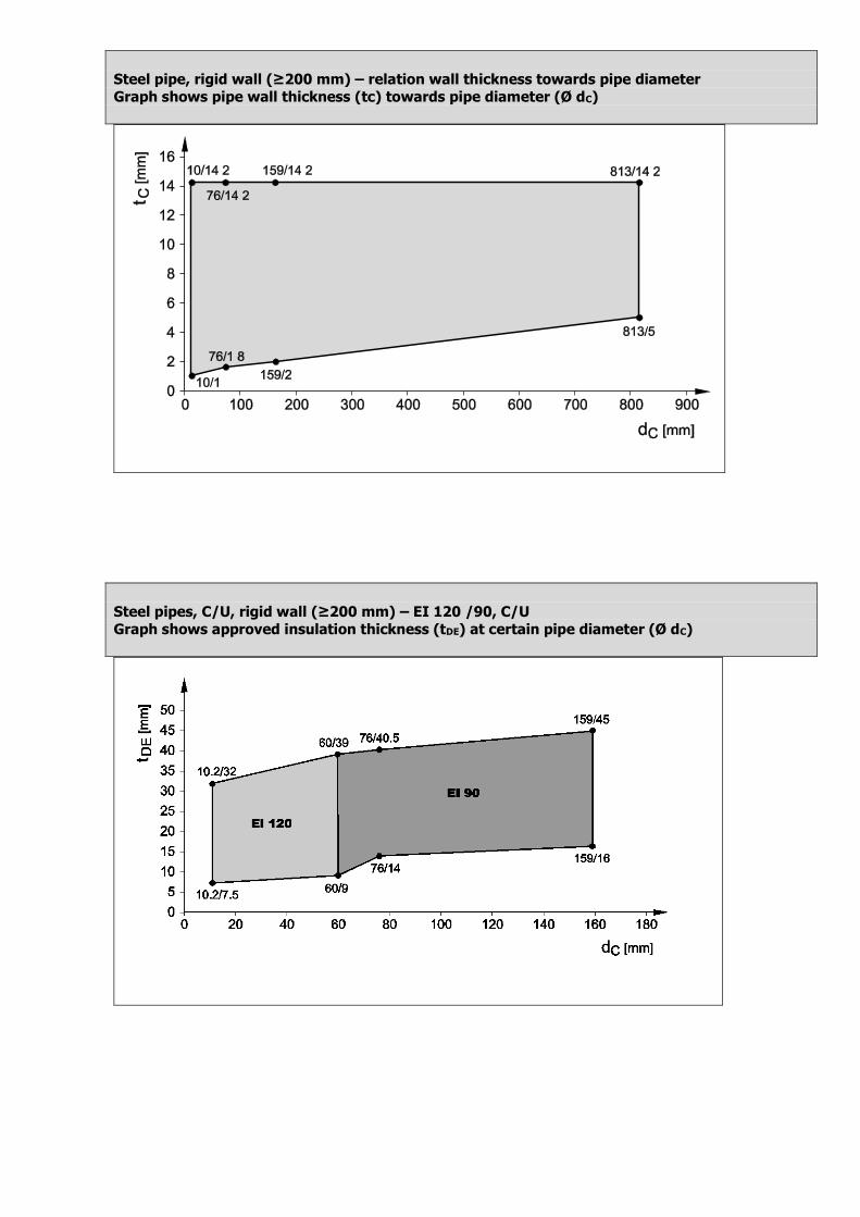
Steel pipe, rigid wall (≥200 mm) – relation wall thickness towards pipe diameter
Graph shows pipe wall thickness (tc) towards pipe diameter (Ø dC)
Steel pipes, C/U, rigid wall (≥200 mm) – EI 120 /90, C/U
Graph shows approved insulation thickness (tDE) at certain pipe diameter (Ø dC)
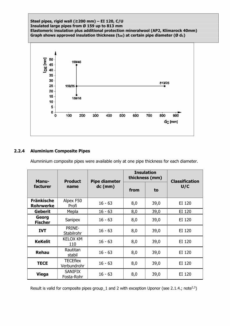
Steel pipes, rigid wall (≥200 mm) – EI 120, C/U
Insulated large pipes from Ø 159 up to 813 mm Elastomeric insulation plus additional protection mineralwool (AP2, Klimarock 40mm)
Graph shows approved insulation thickness (tDE) at certain pipe diameter (Ø dC)
2.2.4 Aluminium Composite Pipes Alumninium composite pipes were available only at one pipe thickness for each diameter.
Manu-facturer
Product name
Pipe diameter dc (mm)
Insulation thickness (mm)
Classification U/C
from to
Fränkische Rohrwerke
Alpex F50 Profi
16 - 63 8,0 39,0 EI 120
Geberit Mepla 16 - 63 8,0 39,0 EI 120
Georg Fischer
Sanipex 16 - 63 8,0 39,0 EI 120
IVT PRINE-
Stabilrohr 16 - 63 8,0 39,0 EI 120
KeKelit KELOX KM
110 16 - 63 8,0 39,0 EI 120
Rehau Rautitan
stabil 16 - 63 8,0 39,0 EI 120
TECE TECEflex
Verbundrohr 16 - 63 8,0 39,0 EI 120
Viega SANIFIX
Fosta-Rohr 16 - 63 8,0 39,0 EI 120
Result is valid for composite pipes group_1 and 2 with exception Uponor (see 2.1.4.; note2,3)
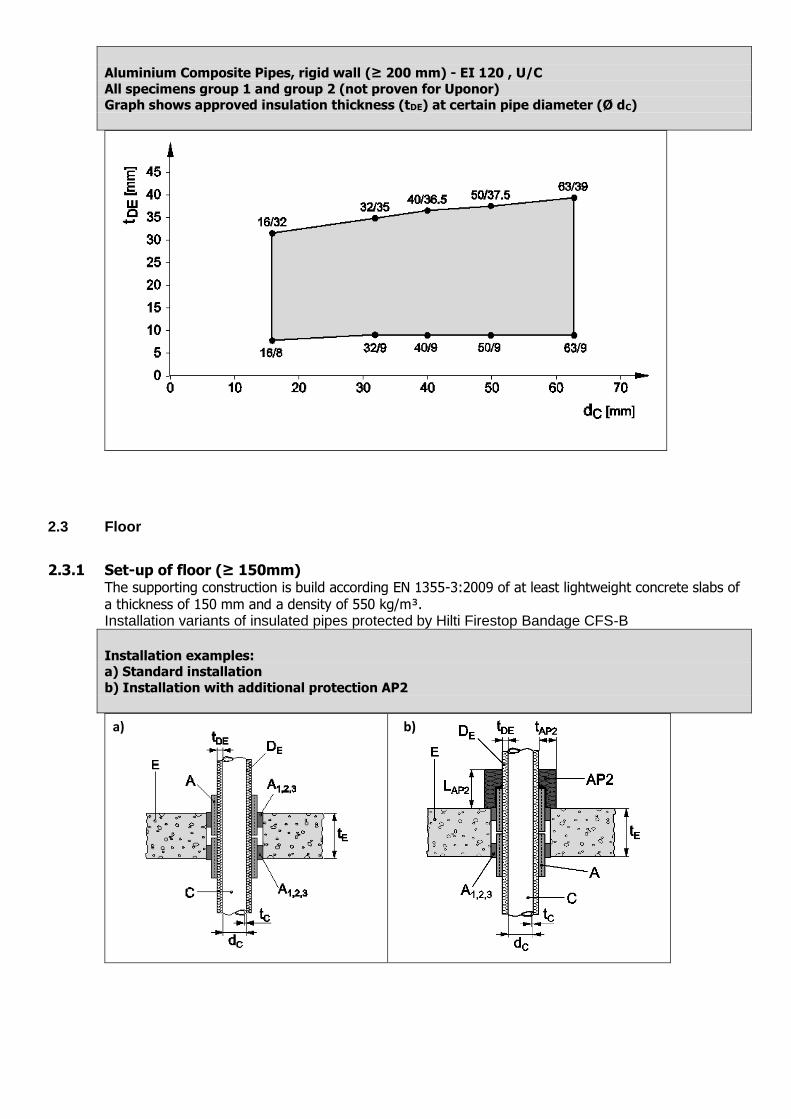
Aluminium Composite Pipes, rigid wall (≥ 200 mm) - EI 120 , U/C
All specimens group 1 and group 2 (not proven for Uponor) Graph shows approved insulation thickness (tDE) at certain pipe diameter (Ø dC)
2.3 Floor
2.3.1 Set-up of floor (≥ 150mm) The supporting construction is build according EN 1355-3:2009 of at least lightweight concrete slabs of a thickness of 150 mm and a density of 550 kg/m³. Installation variants of insulated pipes protected by Hilti Firestop Bandage CFS-B
Installation examples: a) Standard installation
b) Installation with additional protection AP2
a) b)
2.3.2 Copper Pipes
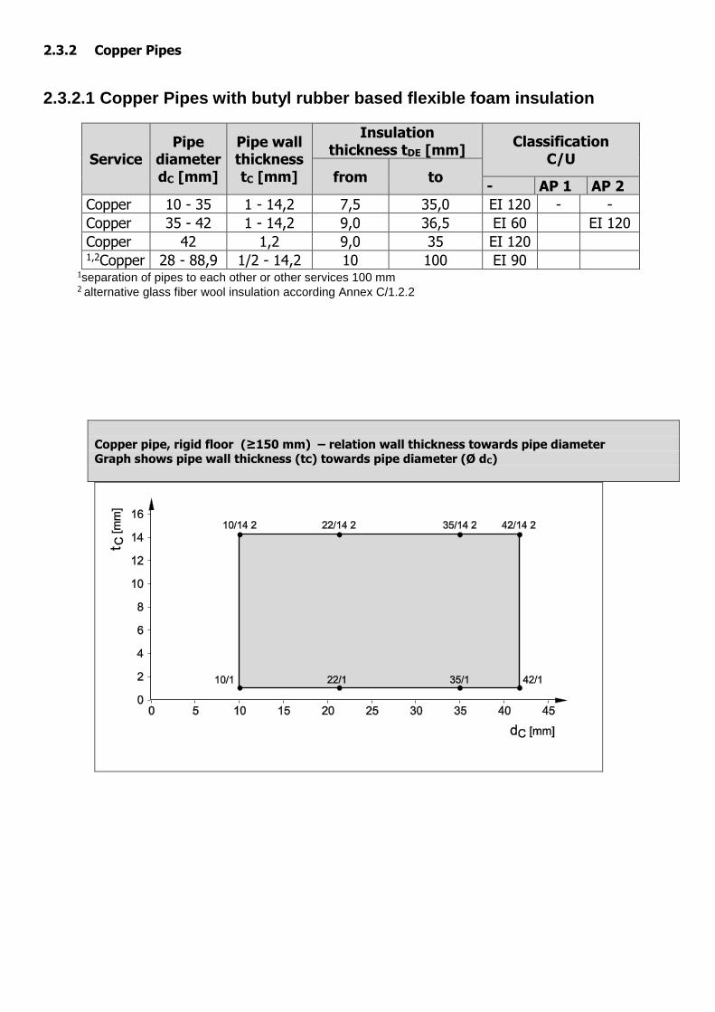
2.3.2.1 Copper Pipes with butyl rubber based flexible foam insulation
Service Pipe
diameter dC [mm]
Pipe wall thickness tC [mm]
Insulation thickness tDE [mm]
Classification C/U
from to - AP 1 AP 2
Copper 10 - 35 1 - 14,2 7,5 35,0 EI 120 - -
Copper 35 - 42 1 - 14,2 9,0 36,5 EI 60 EI 120
Copper 42 1,2 9,0 35 EI 120 1,2Copper 28 - 88,9 1/2 - 14,2 10 100 EI 90
1separation of pipes to each other or other services 100 mm 2 alternative glass fiber wool insulation according Annex C/1.2.2
Copper pipe, rigid floor (≥150 mm) – relation wall thickness towards pipe diameter Graph shows pipe wall thickness (tc) towards pipe diameter (Ø dC)
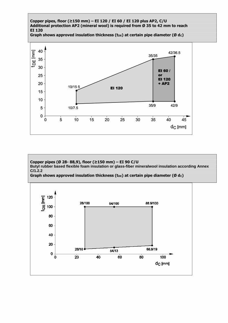
Copper pipes, floor (≥150 mm) – EI 120 / EI 60 / EI 120 plus AP2, C/U
Additional protection AP2 (mineral wool) is required from Ø 35 to 42 mm to reach EI 120
Graph shows approved insulation thickness (tDE) at certain pipe diameter (Ø dC)
Copper pipes (Ø 28- 88,9), floor (≥150 mm) – EI 90 C/U Butyl rubber based flexible foam insulation or glass-fiber mineralwool insulation according Annex C/1.2.2
Graph shows approved insulation thickness (tDE) at certain pipe diameter (Ø dC)
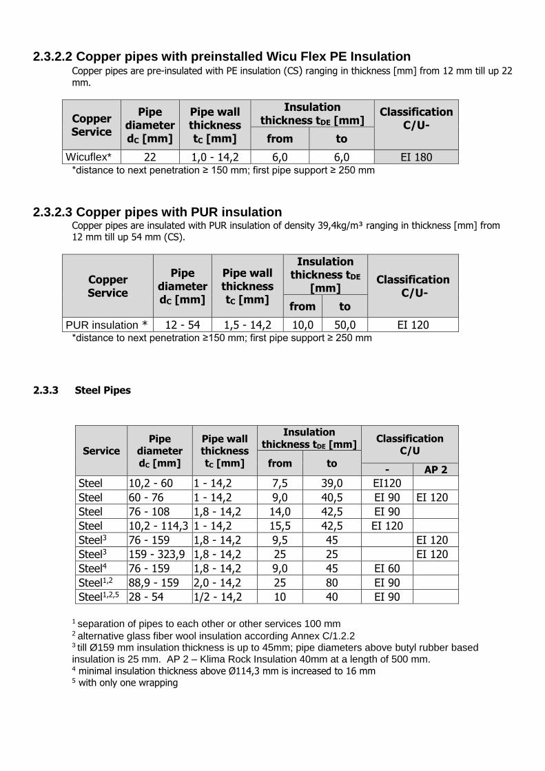
2.3.2.2 Copper pipes with preinstalled Wicu Flex PE Insulation Copper pipes are pre-insulated with PE insulation (CS) ranging in thickness [mm] from 12 mm till up 22
mm.
Copper Service
Pipe diameter dC [mm]
Pipe wall thickness tC [mm]
Insulation thickness tDE [mm]
Classification C/U-
from to
Wicuflex* 22 1,0 - 14,2 6,0 6,0 EI 180 *distance to next penetration ≥ 150 mm; first pipe support ≥ 250 mm
2.3.2.3 Copper pipes with PUR insulation Copper pipes are insulated with PUR insulation of density 39,4kg/m³ ranging in thickness [mm] from 12 mm till up 54 mm (CS).
Copper Service
Pipe diameter dC [mm]
Pipe wall thickness tC [mm]
Insulation thickness tDE
[mm] Classification
C/U-
from to
PUR insulation * 12 - 54 1,5 - 14,2 10,0 50,0 EI 120 *distance to next penetration ≥150 mm; first pipe support ≥ 250 mm
2.3.3 Steel Pipes
Service Pipe
diameter dC [mm]
Pipe wall thickness tC [mm]
Insulation thickness tDE [mm]
Classification C/U
from to - AP 2
Steel 10,2 - 60 1 - 14,2 7,5 39,0 EI120
Steel 60 - 76 1 - 14,2 9,0 40,5 EI 90 EI 120
Steel 76 - 108 1,8 - 14,2 14,0 42,5 EI 90
Steel 10,2 - 114,3 1 - 14,2 15,5 42,5 EI 120
Steel3 76 - 159 1,8 - 14,2 9,5 45 EI 120
Steel3 159 - 323,9 1,8 - 14,2 25 25 EI 120
Steel4 76 - 159 1,8 - 14,2 9,0 45 EI 60
Steel1,2 88,9 - 159 2,0 - 14,2 25 80 EI 90
Steel1,2,5 28 - 54 1/2 - 14,2 10 40 EI 90
1 separation of pipes to each other or other services 100 mm 2 alternative glass fiber wool insulation according Annex C/1.2.2 3 till Ø159 mm insulation thickness is up to 45mm; pipe diameters above butyl rubber based insulation is 25 mm. AP 2 – Klima Rock Insulation 40mm at a length of 500 mm. 4 minimal insulation thickness above Ø114,3 mm is increased to 16 mm 5 with only one wrapping
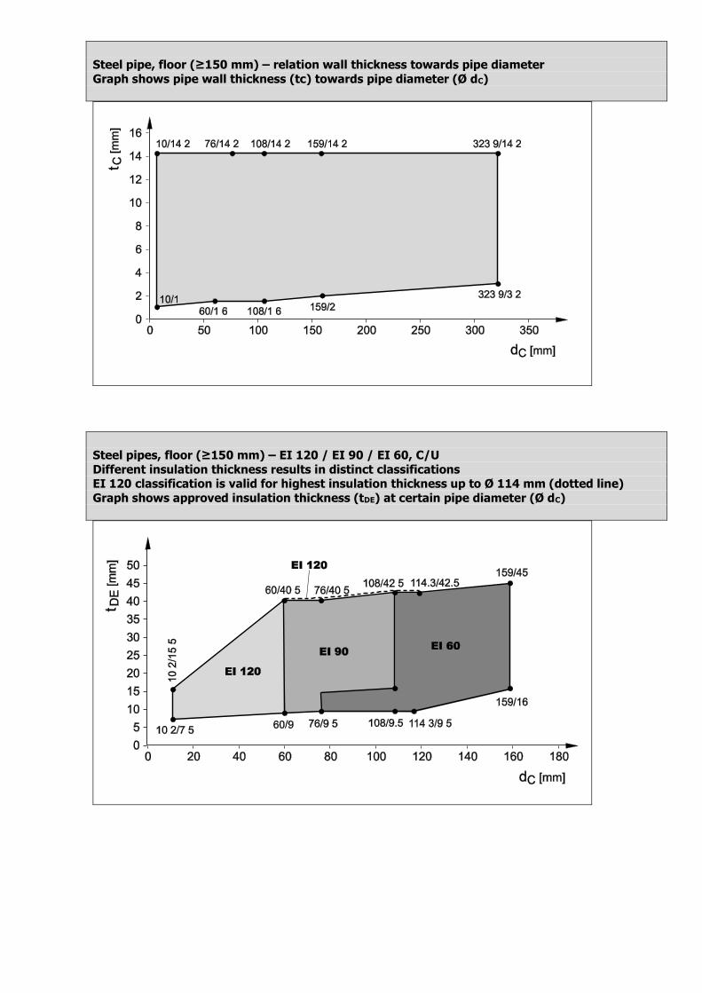
Steel pipe, floor (≥150 mm) – relation wall thickness towards pipe diameter
Graph shows pipe wall thickness (tc) towards pipe diameter (Ø dC)
Steel pipes, floor (≥150 mm) – EI 120 / EI 90 / EI 60, C/U
Different insulation thickness results in distinct classifications EI 120 classification is valid for highest insulation thickness up to Ø 114 mm (dotted line)
Graph shows approved insulation thickness (tDE) at certain pipe diameter (Ø dC)
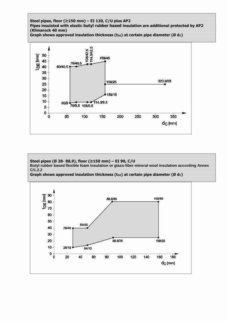
Steel pipes, floor (≥150 mm) – EI 120, C/U plus AP2
Pipes insulated with elastic butyl rubber based insulation are additional protected by AP2
(Klimarock 40 mm)
Graph shows approved insulation thickness (tDE) at certain pipe diameter (Ø dC)
Steel pipes (Ø 28- 88,9), floor (≥150 mm) – EI 90, C/U Butyl rubber based flexible foam insulation or glass-fiber mineral wool insulation according Annex C/1.2.2
Graph shows approved insulation thickness (tDE) at certain pipe diameter (Ø dC)
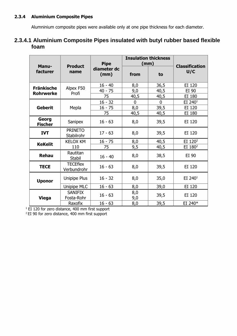
2.3.4 Aluminium Composite Pipes
Alumninium composite pipes were available only at one pipe thickness for each diameter.
2.3.4.1 Aluminium Composite Pipes insulated with butyl rubber based flexible foam
Manu-facturer
Product name
Pipe diameter dc
(mm)
Insulation thickness (mm)
Classification U/C
from to
Fränkische Rohrwerke
Alpex F50 Profi
16 - 40 8,0 36,5 EI 120
40 - 75 9,0 40,5 EI 90
75 40,5 40,5 EI 180
Geberit Mepla
16 - 32 0 0 EI 2401
16 - 75 8,0 39,5 EI 120
75 40,5 40,5 EI 180
Georg Fischer
Sanipex 16 - 63 8,0 39,5 EI 120
IVT PRINETO Stabilrohr
17 - 63 8,0 39,5 EI 120
KeKelit KELOX KM
110
16 - 75 8,0 40,5 EI 1202
75 9,5 40,5 EI 1802
Rehau Rautitan
Stabil 16 - 40 8,0 38,5 EI 90
TECE TECEflex
Verbundrohr 16 - 63 8,0 39,5 EI 120
Uponor Unipipe Plus 16 - 32 8,0 35,0 EI 2401
Unipipe MLC 16 - 63 8,0 39,0 EI 120
Viega
SANIFIX Fosta-Rohr
16 - 63 8,0 9,0
39,5 EI 120
Raxofix 16 - 63 8,0 39,5 EI 240*
1 EI 120 for zero distance, 400 mm first support 2 EI 90 for zero distance, 400 mm first support
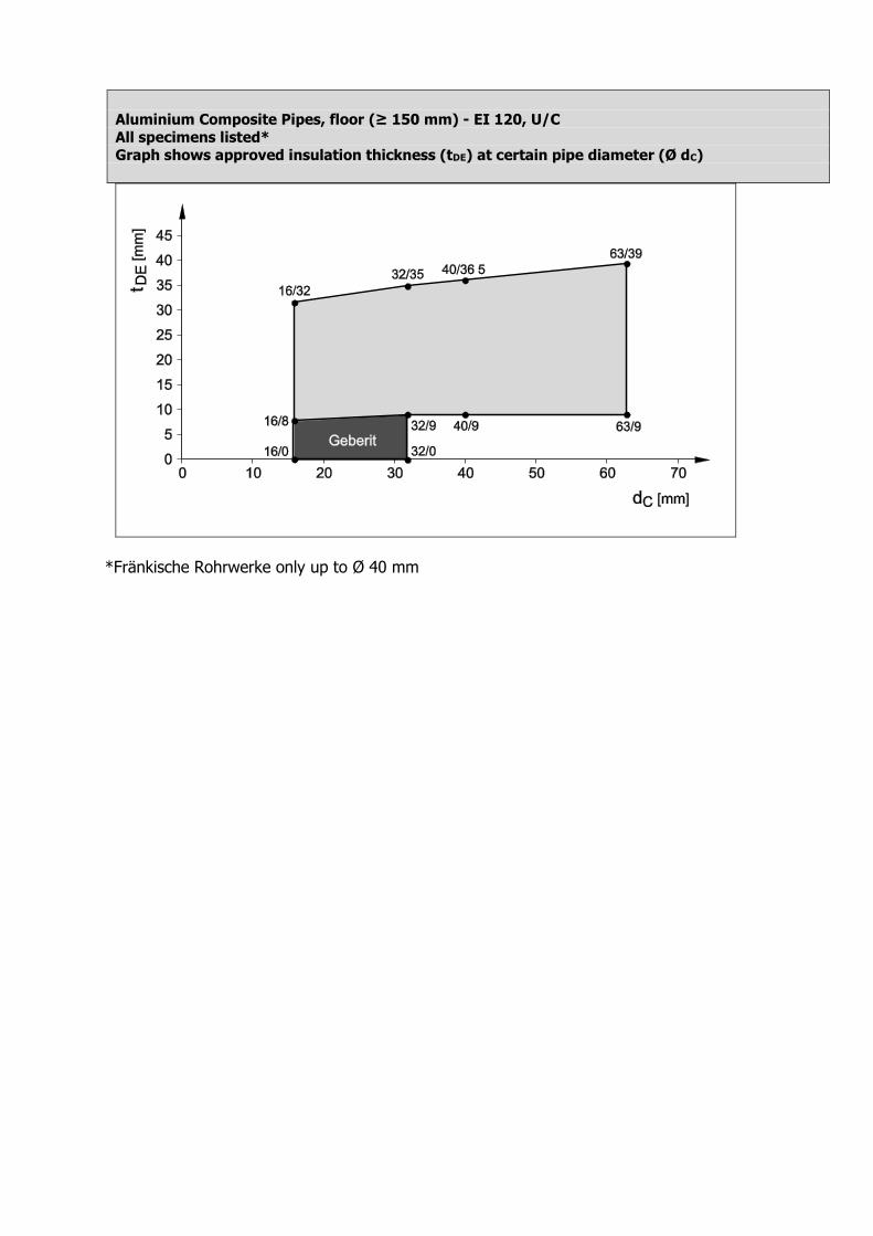
Aluminium Composite Pipes, floor (≥ 150 mm) - EI 120, U/C
All specimens listed*
Graph shows approved insulation thickness (tDE) at certain pipe diameter (Ø dC)
*Fränkische Rohrwerke only up to Ø 40 mm
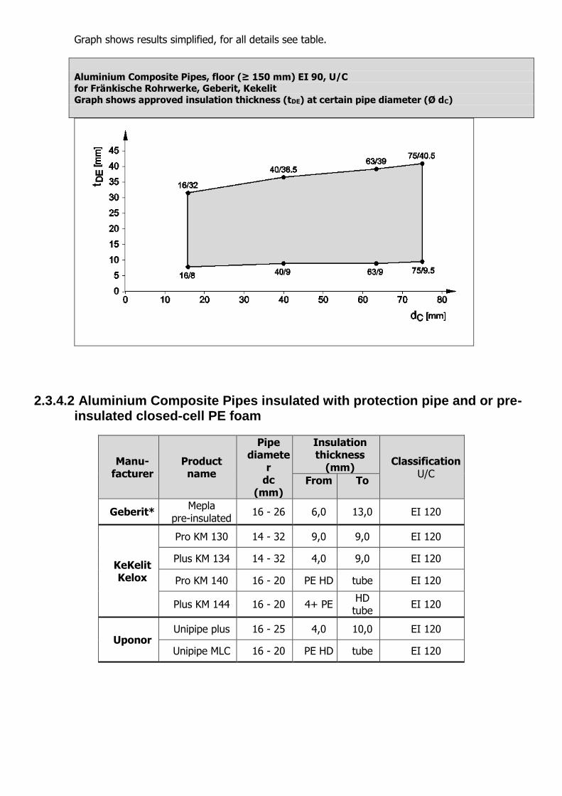
Graph shows results simplified, for all details see table.
Aluminium Composite Pipes, floor (≥ 150 mm) EI 90, U/C
for Fränkische Rohrwerke, Geberit, Kekelit
Graph shows approved insulation thickness (tDE) at certain pipe diameter (Ø dC)
2.3.4.2 Aluminium Composite Pipes insulated with protection pipe and or pre-insulated closed-cell PE foam
Manu-facturer
Product name
Pipe diamete
r dc
(mm)
Insulation thickness
(mm) Classification
U/C From To
Geberit* Mepla
pre-insulated 16 - 26 6,0 13,0 EI 120
KeKelit Kelox
Pro KM 130 14 - 32 9,0 9,0 EI 120
Plus KM 134 14 - 32 4,0 9,0 EI 120
Pro KM 140 16 - 20 PE HD tube EI 120
Plus KM 144 16 - 20 4+ PE HD tube
EI 120
Uponor Unipipe plus 16 - 25 4,0 10,0 EI 120
Unipipe MLC 16 - 20 PE HD tube EI 120
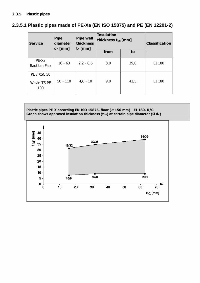
2.3.5 Plastic pipes
2.3.5.1 Plastic pipes made of PE-Xa (EN ISO 15875) and PE (EN 12201-2)
Service
Pipe
diameter
dC [mm]
Pipe wall
thickness
tC [mm]
Insulation
thickness tDE [mm]
Classification
- from to
PE-Xa
Rautitan Flex 16 - 63 2,2 - 8,6 8,0 39,0 EI 180
PE / XSC 50
Wavin TS PE
100
50 - 110 4,6 - 10 9,0 42,5 EI 180
Plastic pipes PE-X according EN ISO 15875, floor (≥ 150 mm) - EI 180, U/C Graph shows approved insulation thickness (tDE) at certain pipe diameter (Ø dC)
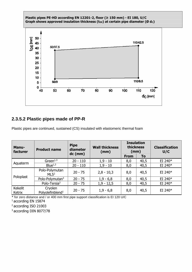
Plastic pipes PE-HD according EN 12201-2, floor (≥ 150 mm) - EI 180, U/C
Graph shows approved insulation thickness (tDE) at certain pipe diameter (Ø dC)
2.3.5.2 Plastic pipes made of PP-R
Plastic pipes are continued, sustained (CS) insulated with elastomeric thermal foam
Manu-facturer
Product name Pipe diameter dc (mm)
Wall thickness (mm)
Insulation thickness
(mm) Classification
U/C
From To
Aquaterm Green1,3 20 - 110 1,9 - 10 8,0 40,5 EI 240*
Blue1,3 20 - 110 1,9 - 10 8,0 40,5 EI 240*
Poloplast
Polo-Polymutan ML52 20 - 75 2,8 - 10,3 8,0 40,5 EI 240*
Polo-Polymutan3 20 - 75 1,9 - 6,8 8,0 40,5 EI 240*
Polo-Tersia3 20 - 75 1,9 - 12,5 8,0 40,5 EI 240*
Kekelit Ketrix
Cryolen Polyolefinblend1 20 - 75 1,9 - 6,8 8,0 40,5 EI 240*
* for zero distance and / or 400 mm first pipe support classification is EI 120 U/C 1 according EN 15874 2 according ISO 21003
3 according DIN 8077/78
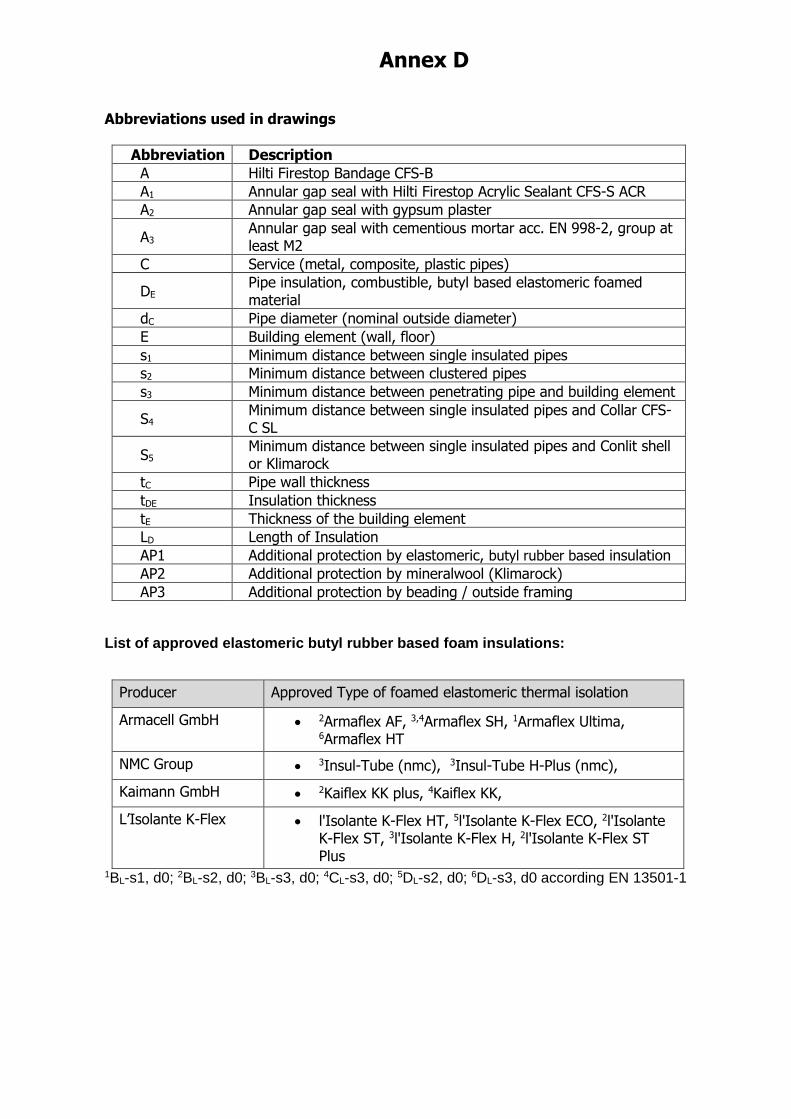
Annex D
Abbreviations used in drawings
Abbreviation Description
A Hilti Firestop Bandage CFS-B
A1 Annular gap seal with Hilti Firestop Acrylic Sealant CFS-S ACR
A2 Annular gap seal with gypsum plaster
A3 Annular gap seal with cementious mortar acc. EN 998-2, group at least M2
C Service (metal, composite, plastic pipes)
DE Pipe insulation, combustible, butyl based elastomeric foamed material
dC Pipe diameter (nominal outside diameter)
E Building element (wall, floor)
s1 Minimum distance between single insulated pipes
s2 Minimum distance between clustered pipes
s3 Minimum distance between penetrating pipe and building element
S4 Minimum distance between single insulated pipes and Collar CFS-C SL
S5 Minimum distance between single insulated pipes and Conlit shell or Klimarock
tC Pipe wall thickness
tDE Insulation thickness
tE Thickness of the building element
LD Length of Insulation
AP1 Additional protection by elastomeric, butyl rubber based insulation
AP2 Additional protection by mineralwool (Klimarock)
AP3 Additional protection by beading / outside framing
List of approved elastomeric butyl rubber based foam insulations:
Producer Approved Type of foamed elastomeric thermal isolation
Armacell GmbH 2Armaflex AF, 3,4Armaflex SH, 1Armaflex Ultima, 6Armaflex HT
NMC Group 3Insul-Tube (nmc), 3Insul-Tube H-Plus (nmc),
Kaimann GmbH 2Kaiflex KK plus, 4Kaiflex KK,
L’Isolante K-Flex l'Isolante K-Flex HT, 5l'Isolante K-Flex ECO, 2l'Isolante K-Flex ST, 3l'Isolante K-Flex H, 2l'Isolante K-Flex ST Plus
1BL-s1, d0; 2BL-s2, d0; 3BL-s3, d0; 4CL-s3, d0; 5DL-s2, d0; 6DL-s3, d0 according EN 13501-1