Embed Size (px)
Citation preview

1
Jalil Kianfar, Ph.D. Assistant Professor of Civil Engineering Parks College of Engineering, Aviation and Technology Saint Louis University 3450 Lindell Blvd, Rm 2037 St. Louis, MO 63103 Phone (314) 977-8271 Email [email protected] November 19, 2015

2
3
Entrepreneurship and Transportation
4
Intelligent Transportation Systems
What is ITS?

5
History of ITS

6

7
What is a traffic detector? Traffic detector is….
What parameters it collects:
7

8
What is a traffic detector Traffic detector is….
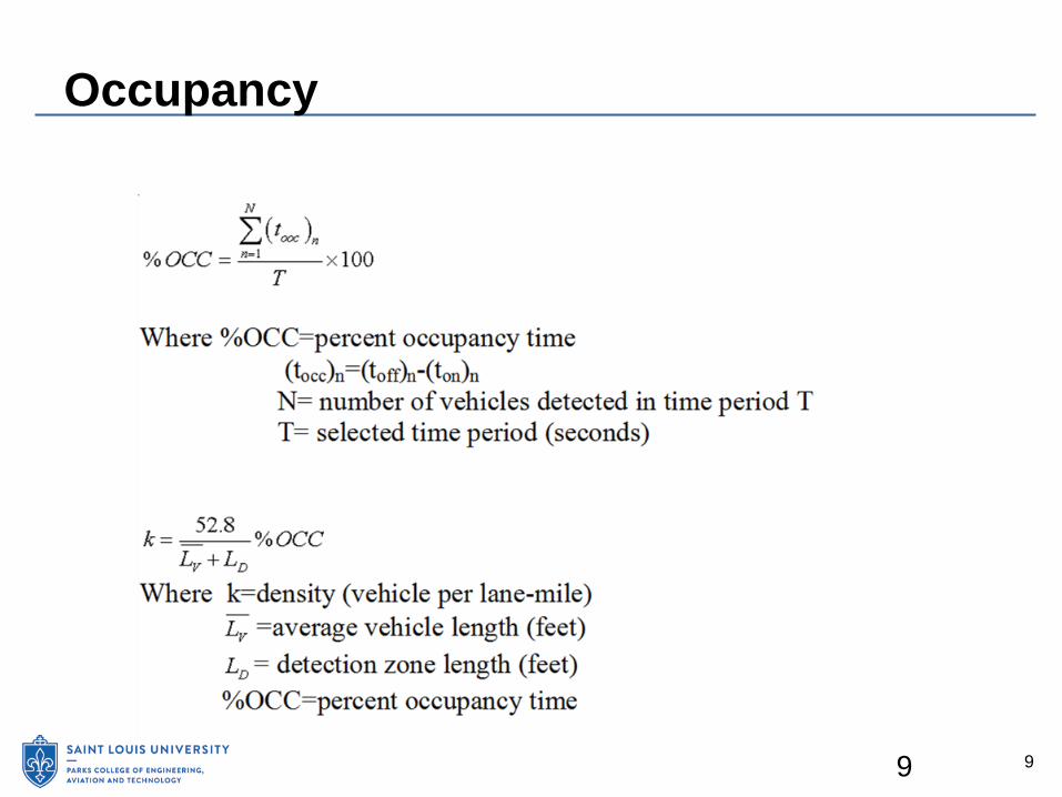
□ an integral part of ITS that automatically collects traffic parameters Which parameters are collected?
□ Flow □ Speed □ Occupancy (Density) □ Time Headway □ Vehicle Classification
8
9
Occupancy
9

10
Examples of Detector Data Applications Travel Time Estimation Congestion Maps Incident Detection Traffic Signals Ramp Metering Enforcement Equipments HPMS Program Traffic Studies
10

11
Modern Traffic Detectors IN-ROADWAY SENSORS (Intrusive)
□ Embedded in the pavement of the roadway, □ Embedded in the subgrade of the roadway, □ Taped or otherwise attached to the surface of the roadway.
OVER-ROADWAY SENSORS (Non-Intrusive) □ Above the roadway or □ Alongside the roadway, offset from the nearest traffic lane by some distance.
11
12
Modern Traffic Detectors Pneumatic Magnetic Inductive Loop Microwave Video Image Processing Piezoelectric Acoustic Ultrasonic Infrared
12

13
Inductive Loop Detectors (ILD)
13

14
Inductive Loop Detectors (ILD)
Presence or passage of a vehicle causes an increase in the oscillation frequency, controller unit logs presence or passage.
14

15
Speed Measurement with ILD
Trade-offs for space between detectors:
15

16
Speed Measurement with ILD
Trade-offs for space between detectors:
Long distance:
Vehicle Lane Change Short distance:
Sensor Cross Talk

17
Magnetic sensors are passive devices that indicate the presence of a metallic object by detecting the perturbation (known as a magnetic anomaly) in the Earth’s magnetic field created by the object.
Magnetic Detectors

18
Perturbation of Earth’s magnetic field by a ferrous metal vehicle
(Drawing courtesy of Nu-Metrics, Vanderbilt, PA)
19
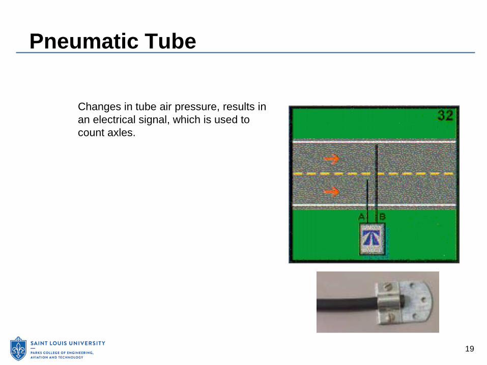
Pneumatic Tube
Changes in tube air pressure, results in an electrical signal, which is used to count axles.
20
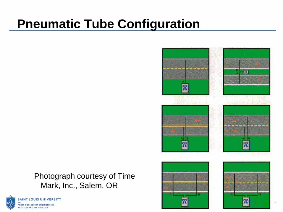
Pneumatic Tube Configuration
Photograph courtesy of Time Mark, Inc., Salem, OR

21
Microwave Radar (RTMS) The Remote Traffic Microwave Sensor (RTMS) is a radar vehicle detector. Capable
of measuring the distance to objects by radiated and reflected microwave signals.
22
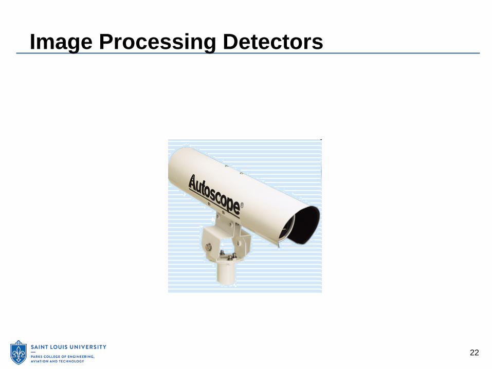
Image Processing Detectors

23
Image Processing Detectors
23

24
Modern Traffic Detectors Pneumatic Magnetic Inductive Loop Microwave Video Image Processing Piezoelectric Acoustic Ultrasonic Infrared
24

25
Other detection methods Cell phones GPS AVI/AVL Connected Vehicles
Pedestrian detectors Bike detectors
25
26
Detector Selection Factors Traffic Parameters Needed Cost Maintenance Accuracy Environmental Conditions Power and Communication Needs
26

27
References The Vehicle Detector Clearinghouse, “A Summary of Vehicle Detection and
Surveillance Technologies used in Intelligent Transportation Systems”, August 2007 ITS Decision, www.calccit.org, accessed September 12, 2009.
27

28
Connected Vehicles

30
Learning Objectives
1. Provide an overview of the connected vehicle program 2. Understand history, evolution, and future direction of
connected vehicle program 3. Understand partnership and roles of government and
industry 4. Understand basic technologies and core systems 5. Understand key policy, legal, and funding issues

31
Definition of a Connected Vehicle Environment
Wireless connectivity among vehicles, the infrastructure, and mobile devices, resulting in transformative change to:
Highway safety Mobility Environmental impacts
Source: USDOT

32
Wireless Communications for Connected Vehicles
Core technology for Connected Vehicle applications Safety-related systems to be based on Dedicated Short
Range Communications Non-safety applications may be based on other
technologies
Source: USDOT
DSRC characteristics: 75 MHz of bandwidth at 5.9
GHz Low latency Limited interference Performance under adverse
conditions
33
Connected Vehicle Benefits
Connected Vehicles will benefit the public good by:
Reducing highway crashes □ Potential to address up to 81% of unimpaired crashes Improving mobility Reducing environmental impact
Additional benefits to public agency transportation system management and operations
34
Historical Context
Current program results from more than a decade of research: 2003 – Vehicle Infrastructure Integration (VII) program
formed by USDOT, AASHTO, and carmakers 2006 – VII Concept of Operations published by USDOT 2008-2009 – VII Proof-of-Concept in Michigan and
California 2010-2011 – VII renamed to Connected Vehicle
program

35
Connected Vehicle Program Today
Current research addresses key strategic challenges: Remaining technical challenges Testing to determine actual benefits Determining if benefits are sufficient to warrant
implementation Issues of public acceptance

36
Key Decision Points
Decisions to be made on core technologies: □ 2013 NHTSA agency decision on
implementation of DSRC in light vehicles
□ 2014 decision regarding DSRC in heavy vehicles
□ Information to support the decision will come from multiple sources, including the Safety Pilot Model Deployment

37
Connected Vehicle Safety Pilot
2,800 vehicles (cars, buses, and trucks) equipped with V2V devices Provide data for
determining the technologies’ effectiveness at reducing crashes Includes vehicles with
embedded equipment and others that use aftermarket devices or a simple communications beacon
Image source: USDOT

38
Safety Pilot V2V Applications
Applications to be tested include: □ Forward Collision Warning □ Electronic Emergency
Brake Lights □ Blind Spot Warning/Lane
Change Warning □ Intersection Movement Assist □ Do Not Pass Warning □ Left Turn Assist
Source: USDOT

39
V2I Safety Applications
Use data exchanged between vehicles and roadway infrastructure to identify high-risk situations and issue driver alerts and warnings □ Traffic signals will communicate
signal phase and timing (SPaT) data to vehicles to deliver active safety messages to drivers
Source: USDOT
40
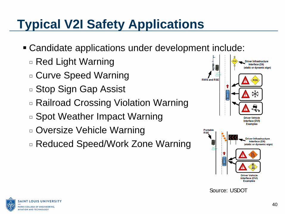
Typical V2I Safety Applications
Candidate applications under development include: □ Red Light Warning □ Curve Speed Warning □ Stop Sign Gap Assist □ Railroad Crossing Violation Warning □ Spot Weather Impact Warning □ Oversize Vehicle Warning □ Reduced Speed/Work Zone Warning
Source: USDOT
41
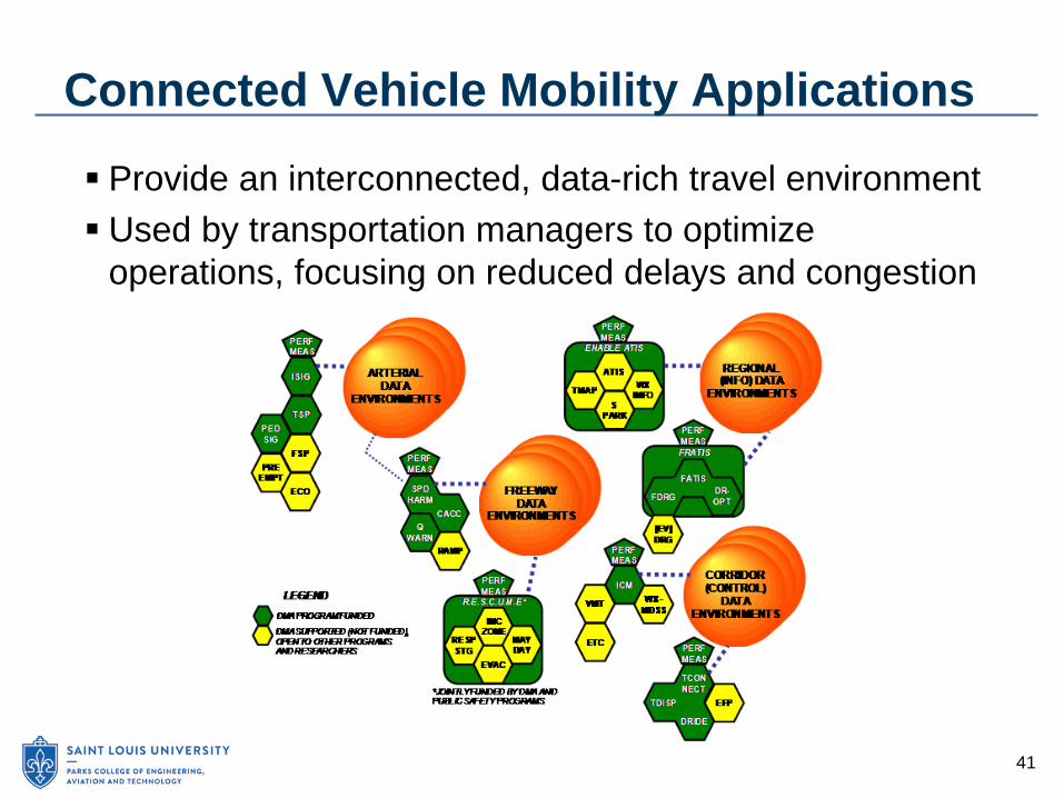
Connected Vehicle Mobility Applications
Provide an interconnected, data-rich travel environment Used by transportation managers to optimize
operations, focusing on reduced delays and congestion

42
Potential Dynamic Mobility Applications
EnableATIS – support sharing of travel information IDTO – support transit
mobility, operations, and services MMITSS – maximize
arterial flows for transit, freight, emergency vehicle, and pedestrians
INFLO – optimize flow with queue warning and speed harmonization R.E.S.C.U.M.E. – support
incident management and mass evacuations FRATIS – freight-specific
information systems or drayage optimization
43
Connected Vehicle Transit Applications
Three Integrated Dynamic Transit Operations (IDTO) applications developed: □ Dynamic Transit Operations (T-DISP) □ Connect Protection (T-CONNECT) □ Dynamic Ridesharing (D-RIDE) Additional transit safety applications in the Safety Pilot: □ Emergency Electronic Brake Lights (EEBL) □ Forward Collision Warning (FCW) □ Vehicle Turning Right in Front of Bus Warning (VTRW) □ Curve Speed Warning (CSW) □ Pedestrian in Crosswalk Warning (PCW)

44
Connected Vehicle Environmental Applications
Generate and capture relevant, real-time transportation data to support environmentally friendly travel choices for: □ Travelers □ Road operating agencies □ Car, truck, and transit drivers
45
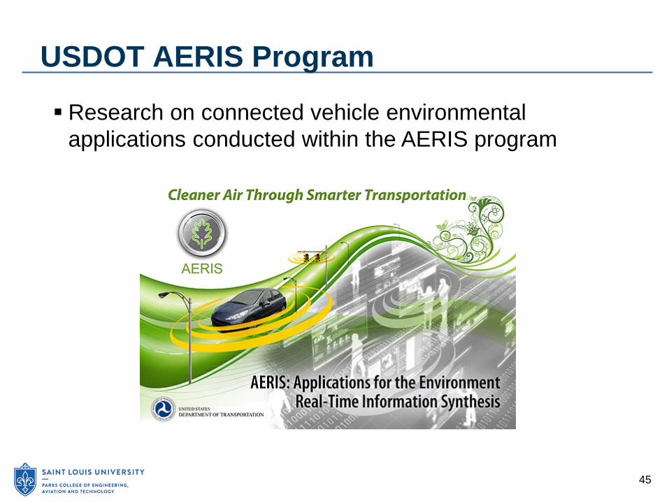
USDOT AERIS Program
Research on connected vehicle environmental applications conducted within the AERIS program

46
Connected Vehicle Environmental Applications
Generate and capture relevant, real-time transportation data to support environmentally friendly travel choices □ Travelers avoid congestion, take alternate routes or
transit, or reschedule their trip to be more fuel-efficient □ Operators receive real-time information on vehicle
location, speed, and other operating conditions to improve system operation
□ Drivers optimize the vehicle's operation and maintenance for maximum fuel efficiency

47
Potential AERIS Concepts
Eco-Signal Operations – Optimize roadside and traffic signal equipment to collect and share relevant positional and emissions data to lessen transportation environmental impact. Dynamic Eco-Lanes – Like HOT and HOV lanes but
optimized to support freight, transit, alternative fuel, or regular vehicles operating in eco-friendly ways Dynamic Low Emissions Zones – Similar to cordon
areas with fixed infrastructure but designed to provide incentives for eco-friendly driving

48
Connected Vehicle Technology
Onboard or mobile equipment Roadside equipment
Communications systems Core systems Support systems
Source: USDOT
49
Dedicated Short-Range Communications
Technologies developed for vehicular communications □ FCC allocated 75 MHz of spectrum in 5.9 GHz band □ To be used to protect the safety of the traveling public A communications protocol similar to WiFi □ Derived from the IEEE 802.11 standard □ DSRC includes WAVE Short Message protocol defined
in IEEE 1609 standard Typical range of a DSRC access point is 300 m □ Typical installations at intersections and other roadside
locations

50
Key DSRC Functional Capabilities
DSRC is the only short-range wireless technology that provides: □ Fast network acquisition, low-latency, high-reliability
communications link □ An ability to work with vehicles operating at high
speeds □ An ability to prioritize safety messages □ Tolerance to multipath transmissions typical of
roadway environments □ Performance that is immune to extreme weather
conditions (e.g., rain, fog, snow) □ Protection of security and privacy of messages

51
DSRC for Active Safety Applications
Source: USDOT

52
Cellular Communications
USDOT committed to DSRC for active safety, but will explore other wireless technologies Cellular communications is a candidate for some safety,
mobility, and environmental applications □ LTE technologies can provide high-speed data rates to
a large number of users simultaneously □ Technologies are intended to serve mobile users □ Good coverage – all urban areas and most major
highways
53
Security Credential Management
Connected Vehicle Environment relies on the ability to trust the validity of messages between users □ Accidental or malicious issue of false messages could
have severe consequences Users also have expectation of appropriate privacy in
the system Current research indicates use of PKI security system
and exchange of digital certificates
54
Policy and Institutional Issues
May limit successful deployment Collaborative effort among USDOT, industry
stakeholders, vehicle manufacturers, state and local governments, associations, and citizens Policy issues and associated research fall into four
categories: □ Implementation Policy Options □ Technical Policy Options □ Legal Policy Options □ Implementation Strategies

55
Implementation Policy Options
Topics to be addressed: □ Viable options for financial and investment strategies □ Analysis and comparisons of communications systems
for data delivery □ Model structures for governance with identified roles
and responsibilities □ Analyses required to support the NHTSA agency
decision
56
Technical Policy Options
Analysis of technical choices for V2V and V2I technologies and applications □ Identify if options require new institutional models or
can leverage existing assets and personnel Technical analyses related to Core System, system
interfaces, and device certification and standards

57
Legal Policy Options
Analysis on the federal role and authority in system development and deployment Analysis of liability and limitations to risk Policy and practices regarding privacy Policies on intellectual property and data ownership
58
Implementation Strategies
AASHTO conducted a Connected Vehicle Field Infrastructure Deployment Analysis □ Infrastructure deployment decisions by state and local
transportation agencies depend on nature and timing of benefits
□ Benefits depend on availability of Connected Vehicle equipment installed in vehicles ▪ Original equipment ▪ After-market devices

59
Connected Vehicle Market Growth
Source: USDOT
60
Funding for Infrastructure Deployment
Key task facing state and local DOTs is the need to identify a funding mechanism. □ Capital and ongoing operations and maintenance costs Agencies can consider various funding categories to
support deployment. □ ITS budget or federal/state funds with ITS eligibility □ Safety improvement program □ Funds set aside for congestion mitigation or air quality
improvement projects □ Public–private partnerships
61
Summary
The Connected Vehicle Environment: □ Wireless connectivity among vehicles, infrastructure,
and mobile devices □ Transformative changes in highway safety, mobility,
and environmental impact □ Broad stakeholder base – government, industry,
researchers Potential benefits □ Use of V2V and V2I may address 81% of unimpaired
crashes in all vehicle types □ Reduce congestion and vehicle emissions

62
Summary (cont’d)
Current strategic challenges – technical, benefits, deployment, public acceptance Connected Vehicle Safety Pilot to support NHTSA
agency decisions in 2013 and 2014 Applications allow systems and technologies to deliver
services and benefits to users in three broad categories □ Safety applications (including those based on V2V or
V2I communications) □ Dynamic mobility applications □ Environmental applications

63
Summary (cont’d)
DSRC technologies developed specifically for vehicular communications □ Reserved for transportation safety by the FCC DSRC will be used for V2V and V2I active safety □ Cellular communications can be explored for other
safety, mobility, and environmental applications A Public Key Infrastructure (PKI) security system,
involving the exchange of digital certificates among trusted users, can support both the need for message security and provide appropriate anonymity to users.
64
Summary (cont’d)
Policy and institutional issues are topics that may limit or challenge successful deployment. An AASHTO Connected Vehicle field infrastructure
deployment analysis indicates: □ Infrastructure deployment decisions of state and local
transportation agencies will be based on the nature and timing of benefits
□ Benefits will depend on the availability of Connected Vehicle equipment installed in vehicles, either as original equipment or as after-market devices.

65
References
AASHTO Subcommittee on Systems Operations and Management Web site: http://ssom.transportation.org/Pages/default.aspx ITS America Web site: The Connected Vehicle - Next
Generation ITS, http://www.itsa.org/industryforums/connectedvehicle U.S. Department of Transportation, Research and
Innovative Technologies Administration, Web site: Connected Vehicle Research, http://www.its.dot.gov/connected_vehicle/connected_vehicle.htm
67
Autonomies Vehicles
68
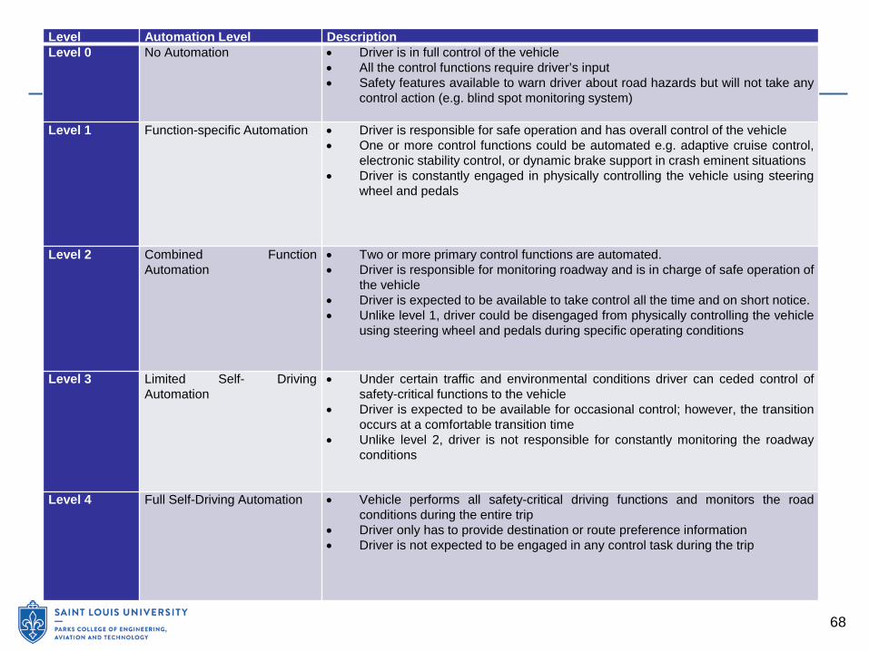
Level Automation Level Description Level 0 No Automation • Driver is in full control of the vehicle
• All the control functions require driver’s input • Safety features available to warn driver about road hazards but will not take any
control action (e.g. blind spot monitoring system)
Level 1 Function-specific Automation • Driver is responsible for safe operation and has overall control of the vehicle • One or more control functions could be automated e.g. adaptive cruise control,
electronic stability control, or dynamic brake support in crash eminent situations • Driver is constantly engaged in physically controlling the vehicle using steering
wheel and pedals
Level 2 Combined Function Automation
• Two or more primary control functions are automated. • Driver is responsible for monitoring roadway and is in charge of safe operation of
the vehicle • Driver is expected to be available to take control all the time and on short notice. • Unlike level 1, driver could be disengaged from physically controlling the vehicle
using steering wheel and pedals during specific operating conditions
Level 3 Limited Self- Driving Automation
• Under certain traffic and environmental conditions driver can ceded control of safety-critical functions to the vehicle
• Driver is expected to be available for occasional control; however, the transition occurs at a comfortable transition time
• Unlike level 2, driver is not responsible for constantly monitoring the roadway conditions
Level 4 Full Self-Driving Automation • Vehicle performs all safety-critical driving functions and monitors the road conditions during the entire trip
• Driver only has to provide destination or route preference information • Driver is not expected to be engaged in any control task during the trip

69
Potential impacts
Safety Congestion and traffic operations Travel-behavior impacts Freight transportation Changes in VMT and vehicle ownership Discount rate and technology costs

71
Barriers to Implementation
Vehicle costs AV certification Litigation, liability and perception Security Privacy