Embed Size (px)
Citation preview
Joshua’s Jumper
BME 4900 Final Report
Team #21 Elyssa Polomski, Michael Ballintyn, Tianyi Xu
Client: Joshua Bouchard
Client Contact: Sue and Ron Bouchard, [email protected], (508) 823-6113
2
Table of Contents:
Abstract……………………………………………………………………………………. 3
1 Introduction……………………………………………………………………………… 3
1.1 Background (Client and Disability)……………………………………………. 3
1.2 Purpose of the project………………………………………………………….. 4
1.3 Previous work done by others…………………………………………………. 4
1.3.1 Products……………………………………………………………. 4
1.3.2 Patents……………………………………………………………… 7
1.4 Map of Report………………………………………………………………….. 8
2 Project Design………………………………………………………………………….. 8
2.1 Optimal Design………………………………………………………………… 16
2.1.1 Objective…………………………………………………………… 16
2.1.2 Subunits……………………………………………………………..16
3 Realistic Constraints…………………………………………………………………….28
4 Safety Issues…………………………………………………………………………….29
5 Impact of Engineering Solutions………………………………………………………..30
6 Life-Long Learning…………………………………………………………………….. 30
7 Budget and Timeline…………………………………………………………………….31
7.1 Budget………………………………………………………………………….. 31
7.2 Timeline………………………………………………………………………….33
8 Team Members Contributions to the Project……………………………………………35
8.1 Elyssa Polomski…………………………………………………………………35
8.2 Michael Ballintyn………………………………………………………………..35
8.3 Tianyi Xu………………………………………………………………………..36
9 Conclusion……………………………………………………………………………….36
10 References……………………………………………………………………………… .37
11 Acknowledgements…………………………………………………………………….. .37
12 Appendix……………………………………………………………………………….. .38
3
Abstract
The client has expressed a need for a motorized device which will allow for a child with
cerebral palsy to be free to remain in a standing position and jump for an extended period of
time. The client, Joshua Bouchard, is a nine year old male with cerebral palsy and has difficulty
maintaining his balance and standing under his own power. The device will be an adaptation of a
popular baby-bouncing apparatus, and will be motorized to allow for easy transportation of
Joshua. By allowing him to remain in a standing position for an extended amount of time, Joshua
will be able to strengthen the muscles in his legs and aid him in learning how to maintain his
own balance.
The device will be constructed out of lightweight, yet stable, aluminum, allowing for
ample support of Joshua, without compromising the safety and structure of the device. The
harness will provide support to Joshua, particularly in the torso and pelvic regions to promote a
proper standing position and allow him to strengthen his legs without having to support his entire
body weight. The motorized portion of the device will have two sets of controls. One set will be
used primarily by Joshua’s parents, where they will be able to remotely control the device. The
other set of controls will be available for Joshua to use. These controls will ultimately help to
adjust Joshua to those of a motorized wheelchair, which his parents hope to have him using in
the future. There will be a safety features in place, such as the ability for the parental controls to
override all activity, and an emergency kill switch, to ensure that Josh can practice controlling he
device while under parental supervision.
The budget for Joshua’s Jumper has been determined to be $2000. This is a reasonable
cost, considering that there are multiple components to this project, and the desire to have the
device remotely controlled and motorized has increased the price dramatically. While the project
may be costly, the effect it will have on Joshua’s quality of life will be greatly beneficial to both
Joshua and his family. By including the motorized components into the design, it will allow
Joshua’s family more freedom to move him about the house and other family outings. Also, by
providing Joshua with his own set of controls, he will be able to improve his fine motor skills,
with the goal of one day controlling his own motorized wheelchair. Both the controls and the
adjustable, portable nature of the device will be incredibly beneficial to the client and well worth
the time and effort required to manufacture it.
1 Introduction
1.1 Background
This project is for the client, Joshua Bouchard, a nine year old male with Cerebral Palsy. His
medical condition stemmed from a brain injury at birth and has therefore made him completely
dependent on assistance from his parents and caregivers. As is the case with many children with
Cerebral Palsy, Joshua has both mental and physical limitations. He is unable to talk, and
therefore has a more difficult time expressing his thoughts and emotions. It is clear, though, that
he thoroughly enjoys being in a standing position and being able to use his legs to jump, when he
is assisted by his parents.
Due to his physical limitations, Joshua is wheelchair bound and unable to support his own
weight or maintain balance when placed into a standing position. Because he spends a vast
majority of his time in the wheelchair, his core and leg muscles, which are required to stand and
maintain balance, are not as developed. Aside from affecting his ability to stand and jump
4
without assistance, Joshua’s condition also affects his fine motor skills and ability to manipulate
controls with his hands. His therapist and parents have indicated that, ideally, Joshua would be
transferred to a motorized wheelchair in the future. This would require a great deal of therapy
and practice, but could be accomplished over time.
1.2 Purpose of the project
The purpose of this project is to provide Joshua with a means to have more freedom to do
what he loves, while keeping him safe and allowing for muscular development and coordination.
The client has expressed a desire for Joshua to have the ability to remain unassisted in a standing
position, while providing him with enough support to allow him to jump and bounce on his own.
The client has also stated that it would be beneficial if the device were motorized to allow for
easier transport both around the house and wherever the device is taken. Therefore, a device that
is both remotely controlled and easy to transport will make things easier on the parents and
caregivers. This machine could make Joshua at ease with the idea of using a motorized
wheelchair in the future. The device must be strong enough to fully support Joshua and adjust to
any growth in height or weight, while remaining lightweight and portable. In this way, both Joshua and
his entire family will have more freedom.
1.3 Previous Work Done by Others
1.3.1 Products
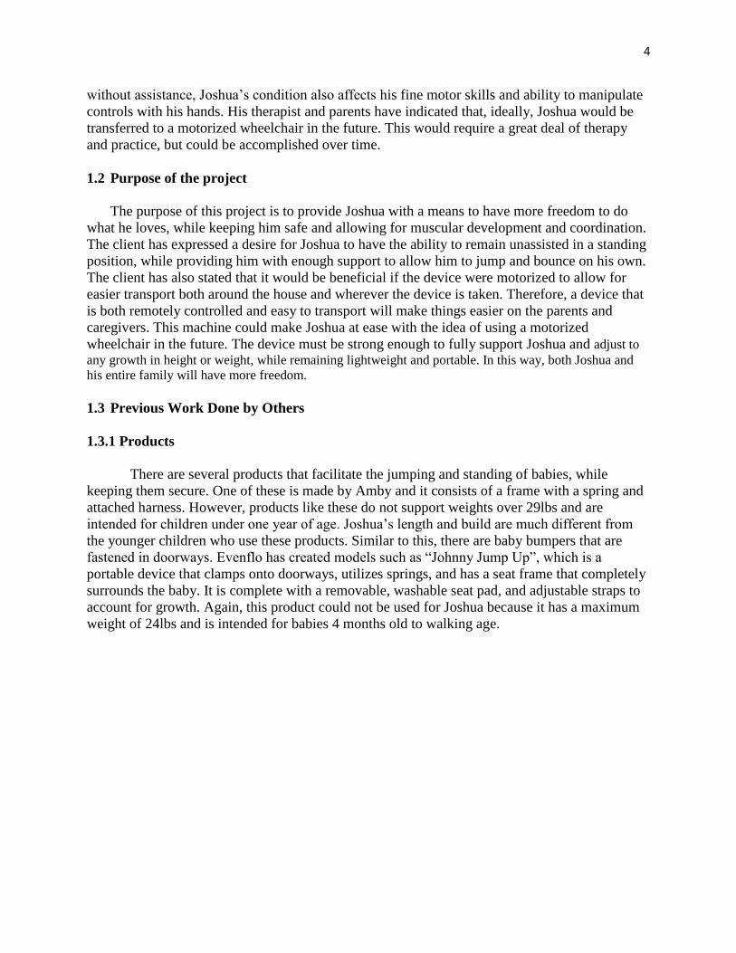
There are several products that facilitate the jumping and standing of babies, while
keeping them secure. One of these is made by Amby and it consists of a frame with a spring and
attached harness. However, products like these do not support weights over 29lbs and are
intended for children under one year of age. Joshua’s length and build are much different from
the younger children who use these products. Similar to this, there are baby bumpers that are
fastened in doorways. Evenflo has created models such as “Johnny Jump Up”, which is a
portable device that clamps onto doorways, utilizes springs, and has a seat frame that completely
surrounds the baby. It is complete with a removable, washable seat pad, and adjustable straps to
account for growth. Again, this product could not be used for Joshua because it has a maximum
weight of 24lbs and is intended for babies 4 months old to walking age.
5
Figure 1: Amby Baby Bed Accessory Figure 2: Evenflo Johnny Jump Up
with Metal Cross Strut Frame.
For the standing, motorized part of the device that will be created, there are some
previous inventions that have aspects desirable for this project. AbleData was used to search
through these products, where the Rifton Large Dynamic Stander, model K170 (Figure 3), was
found. It is a mobile device that fully supports the individual with body supports, straps, fleece,
and a seat pad. The idea of the platform underneath the individual with a frame with four wheels
is a concept that may be used in the production of Joshua’s Jumper. The Rifton is a stander that
can be used with fully dependant individuals and also with ones that have some weight bearing
abilities. A difference in this product and the one that will be created is that Joshua’s legs need
freedom to strengthen them, rather than restrictive braces. This device can also carry a larger
amount of weight (much greater than Joshua, in fact) which would allow him to grow into it. The
price is $2147.00 for the Rifton.
6
Figure 3: The Rifton Large Dynamic Stander.
The Lifestand Compact, LSC, is a motorized wheelchair that allows the user to sit or
stand (with power operated changes), and can be for children or adults. A stiff back frame
provides the supine support for the rear wheel drive machine. This is a very expensive product, at
about $22995.00, because of its compactness, power, and ability to change positions of the user.
Mobility4kids makes a product called “The Go-Bot”, which is another motorized device that is
specifically for children and allows them to sit or stand. It can be operated by children from 1
year of age or older, but under 43 inches tall or 100lbs. It can be used both indoors and outdoors
on flat surfaces and has front wheel drive. A joystick or series of switches are used to operate the
Go-Bot, with an emergency remote for an adult to use to shut off the power. This device has
many of the features necessary for Joshua’s Jumper, except that he would be too tall and too
restricted (unable to jump). Additionally, it is not necessary for him to be able to sit in the
device, which will allow for the design to permit jumping motions. The Go-Bot is priced at about
$5315.00.
Figure 4: Mobility4kids’ Go-Bot.
7
The Universal Exercise Unit (UEU) is a device that utilizes elastic bands attached
through the Therasuit and the “Spider cage” (a suspension-like system). Josh’s parents have told
the team that he has used a cage system in physical therapy, which is most likely this product.
The unit facilitates jumping much like Joshua’s Jumper will. However, it is stationary and a
relatively large device. Additionally, it does not appear to provide the upper body support that
Josh would need in a unit he would use very frequently. The UEU works to improve strength,
muscle flexibility, and active range of motion, which Joshua’s Jumper will also accomplish for
Josh. Figure 5 below shows the UEU in Advanced Pediatric Physical Therapy center with the
user in a seated position.
Figure 5: The Universal Exercise Unit.
1.3.2 Patent Search Results
There are no patents equivalent to what this group is trying to design. The closest that
could be found were for infants to toddlers, and they were not motorized. Walkers are similar
instruments; however, they do not provide the ability to jump that Joshua will have with this
powered jumper. PatentStorm shows that Mattel, Inc. holds the patent on a free-standing jumping
design that is somewhat similar to the group’s design. The Mattel design includes an unattached
frame that supports a seat and resilient members and sleeves at the front and back sections of the
device to maintain stability. The position of the seat is adjustable with the resilient members that
attach to it and the support frame. This design is similar to the team’s design in that it provides a
supporting frame, thus making it independent of being mounted on a door frame like other baby
jumpers. However, this design by Mattel is very different from what the team is creating. This
senior design project differs in the replacement of the seat with a harness, which will secure Josh
better than a seat and provide his legs with more degrees of motion. Josh’s Jumper will be much
larger in size compared to Mattel’s design because Mattel’s device is meant for infants. Josh’s
jumper will also be motorized with a platform that helps to keep Josh from any debris he may
step on in the different environmental surfaces his jumper may be placed on. Unlike an infant
who may not be able to support his/her weight, Josh can support his body with his legs therefore
the team’s device will also allow Josh to perhaps exercise his lower limbs as well as provide him
with entertainment.
8
1.4 Map for the rest of the report
This report will contain the three designs that were created, along with the ultimate
design that was chosen. Within the optimal design section are subunits which are comprised of
explanations of the components of Joshua’s Jumper and why these parts were preferred.
Constraints, safety issues, and engineering lessons will then be discussed to explain the device’s
limitations and what knowledge is gained from the project. The complete budget and the project
timeline are expressed in tabular forms as well as a written description. Finally, the report
includes the contributions of the different team members as well as the acknowledgements of
outside assistance. Attached at the end are the references, purchase requisitions, and additional
information on some of the parts.
2 Project Design
The Project design consists of three alternative designs that were thought to suit this
project and create a final product that would function to meet the objective. After discussing
these designs amongst the team and with the client’s parents, an optimal design was chosen using
different components of the three designs. This design was thought to be the final design, but
was then altered again to be composed of 80/20 Erector set aluminum materials versus the
original idea of aluminum or steel poles. This new material will be easier to put together because
it will not require welding. Additionally, the company has ensured that it will be sturdy enough
and much more lightweight than the previous design. A change in the harness was also made
because one equivalent in quality was found at a lower price. The Alternative Designs are
described below, followed by the Optimal Design containing subunits which detail the different
parts of the device and why they were chosen as the most suitable for this project.
Alternative Design 1
This design will be composed of three primary components: the frame, the harness and
elastic straps, and the motorized platform. Each component must be fabricated and adjusted to fit
Joshua’s unique body type. This device must be built especially stable and structurally sound to
support Joshua’s weight and bouncing motion. To account for these factors, an aluminum frame
will be constructed into a rectangular box. Horizontal aluminum bars will also be welded in
approximately halfway down the frame to both increase stability, and provide a method with
which to keep Joshua from bouncing too far in one direction. These bars will be padded with
durable foam to prevent any injury that may result from bumping into them. One cross bar will
be placed on a hinge, so as to allow for easier access when placing and removing Joshua from
the harness. Another crossbar will also feature a removable control panel which will contain
Joshua’s joystick control. In this way, the device can remain stationary and allow for movement
only via the remote controls. The joystick for Joshua can then be attached only when he is ready
to begin practicing and training towards the use of a motorized wheelchair. The frame will also
be comprised of telescoping poles, allowing for easy height adjustment as Joshua grows over the
next few years.
The second major component is the harness and elastic straps used to support and
suspend Joshua. For this design, a suspension trauma strap will be used to help keep Joshua in
the upright, standing position. As see in Figure 6, this particular strap is quite similar to that of a
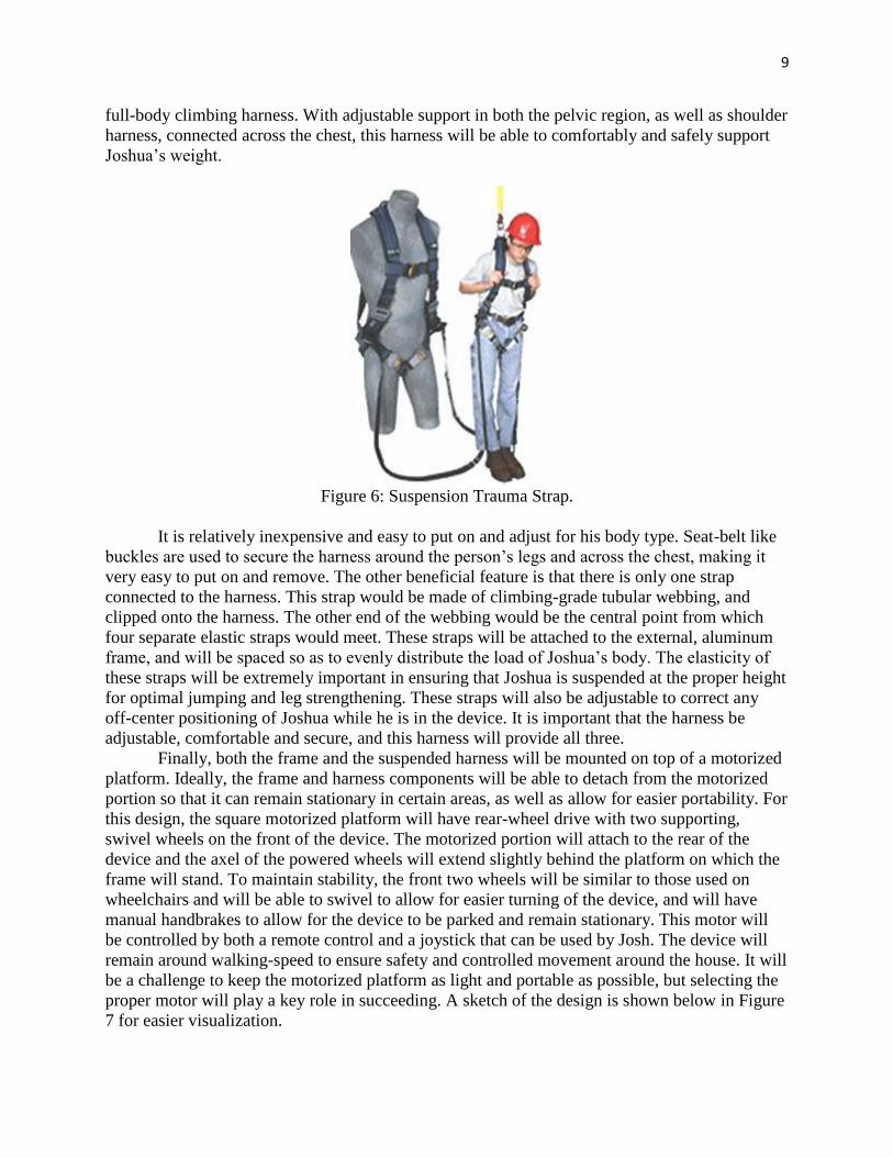
9
full-body climbing harness. With adjustable support in both the pelvic region, as well as shoulder
harness, connected across the chest, this harness will be able to comfortably and safely support
Joshua’s weight.
Figure 6: Suspension Trauma Strap.
It is relatively inexpensive and easy to put on and adjust for his body type. Seat-belt like
buckles are used to secure the harness around the person’s legs and across the chest, making it
very easy to put on and remove. The other beneficial feature is that there is only one strap
connected to the harness. This strap would be made of climbing-grade tubular webbing, and
clipped onto the harness. The other end of the webbing would be the central point from which
four separate elastic straps would meet. These straps will be attached to the external, aluminum
frame, and will be spaced so as to evenly distribute the load of Joshua’s body. The elasticity of
these straps will be extremely important in ensuring that Joshua is suspended at the proper height
for optimal jumping and leg strengthening. These straps will also be adjustable to correct any
off-center positioning of Joshua while he is in the device. It is important that the harness be
adjustable, comfortable and secure, and this harness will provide all three.
Finally, both the frame and the suspended harness will be mounted on top of a motorized
platform. Ideally, the frame and harness components will be able to detach from the motorized
portion so that it can remain stationary in certain areas, as well as allow for easier portability. For
this design, the square motorized platform will have rear-wheel drive with two supporting,
swivel wheels on the front of the device. The motorized portion will attach to the rear of the
device and the axel of the powered wheels will extend slightly behind the platform on which the
frame will stand. To maintain stability, the front two wheels will be similar to those used on
wheelchairs and will be able to swivel to allow for easier turning of the device, and will have
manual handbrakes to allow for the device to be parked and remain stationary. This motor will
be controlled by both a remote control and a joystick that can be used by Josh. The device will
remain around walking-speed to ensure safety and controlled movement around the house. It will
be a challenge to keep the motorized platform as light and portable as possible, but selecting the
proper motor will play a key role in succeeding. A sketch of the design is shown below in Figure
7 for easier visualization.
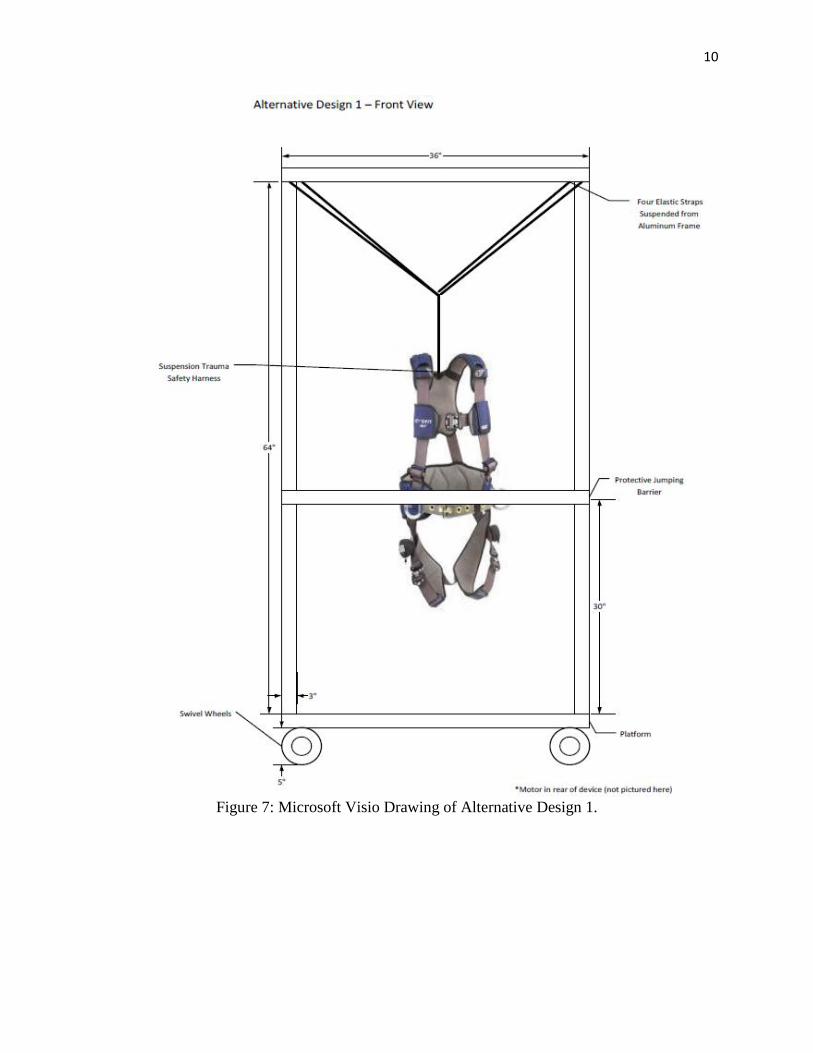
10
Figure 7: Microsoft Visio Drawing of Alternative Design 1.
11
Alternative Design 2
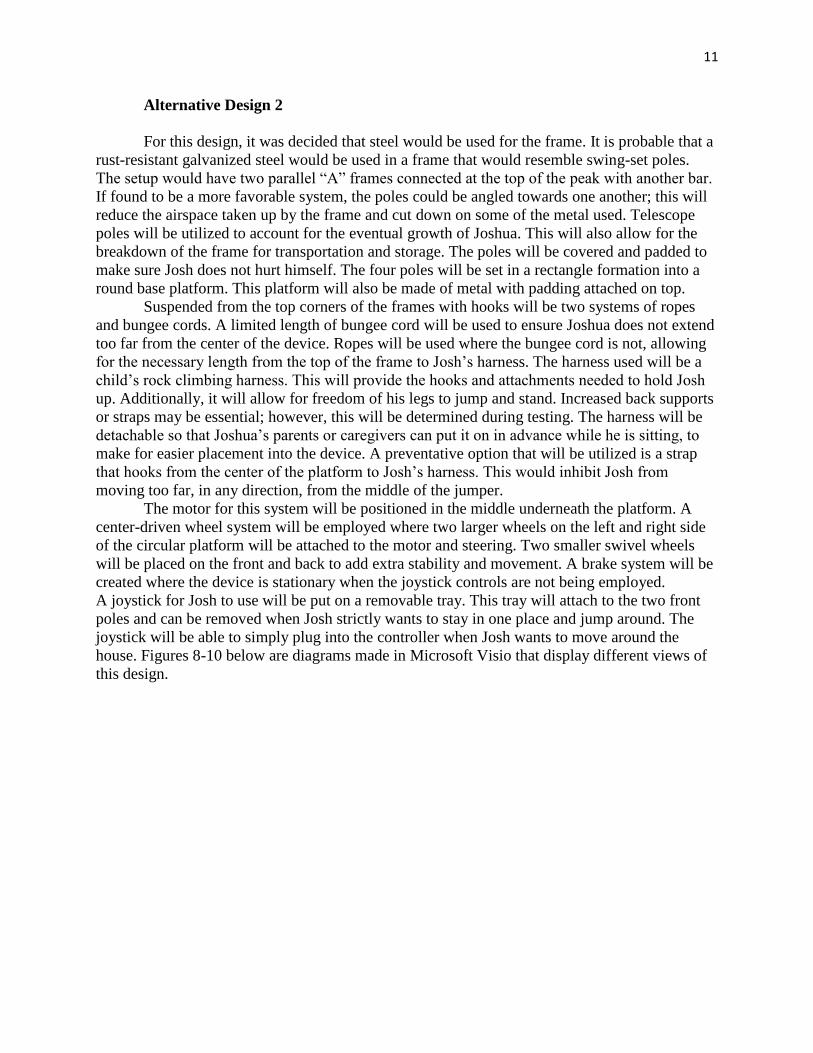
For this design, it was decided that steel would be used for the frame. It is probable that a
rust-resistant galvanized steel would be used in a frame that would resemble swing-set poles.
The setup would have two parallel “A” frames connected at the top of the peak with another bar.
If found to be a more favorable system, the poles could be angled towards one another; this will
reduce the airspace taken up by the frame and cut down on some of the metal used. Telescope
poles will be utilized to account for the eventual growth of Joshua. This will also allow for the
breakdown of the frame for transportation and storage. The poles will be covered and padded to
make sure Josh does not hurt himself. The four poles will be set in a rectangle formation into a
round base platform. This platform will also be made of metal with padding attached on top.
Suspended from the top corners of the frames with hooks will be two systems of ropes
and bungee cords. A limited length of bungee cord will be used to ensure Joshua does not extend
too far from the center of the device. Ropes will be used where the bungee cord is not, allowing
for the necessary length from the top of the frame to Josh’s harness. The harness used will be a
child’s rock climbing harness. This will provide the hooks and attachments needed to hold Josh
up. Additionally, it will allow for freedom of his legs to jump and stand. Increased back supports
or straps may be essential; however, this will be determined during testing. The harness will be
detachable so that Joshua’s parents or caregivers can put it on in advance while he is sitting, to
make for easier placement into the device. A preventative option that will be utilized is a strap
that hooks from the center of the platform to Josh’s harness. This would inhibit Josh from
moving too far, in any direction, from the middle of the jumper.
The motor for this system will be positioned in the middle underneath the platform. A
center-driven wheel system will be employed where two larger wheels on the left and right side
of the circular platform will be attached to the motor and steering. Two smaller swivel wheels
will be placed on the front and back to add extra stability and movement. A brake system will be
created where the device is stationary when the joystick controls are not being employed.
A joystick for Josh to use will be put on a removable tray. This tray will attach to the two front
poles and can be removed when Josh strictly wants to stay in one place and jump around. The
joystick will be able to simply plug into the controller when Josh wants to move around the
house. Figures 8-10 below are diagrams made in Microsoft Visio that display different views of
this design.
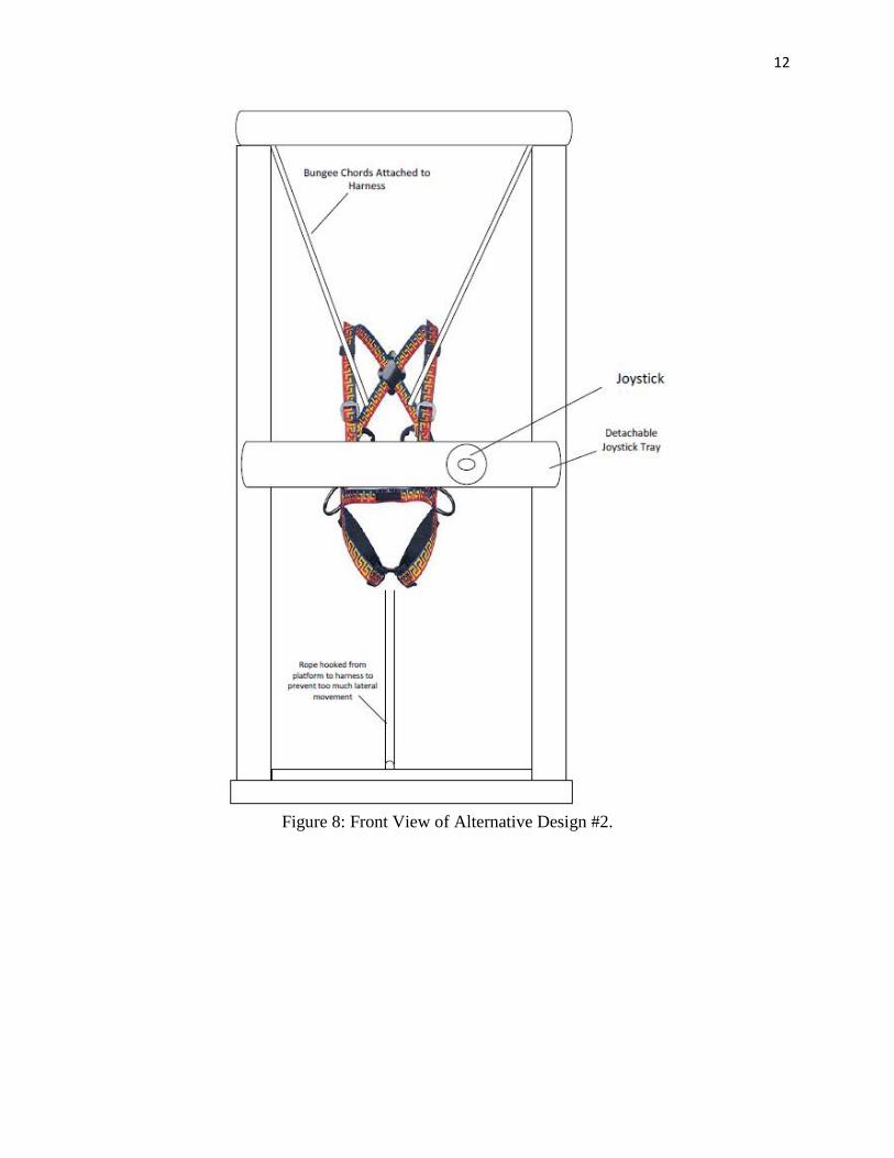
12
Figure 8: Front View of Alternative Design #2.
13
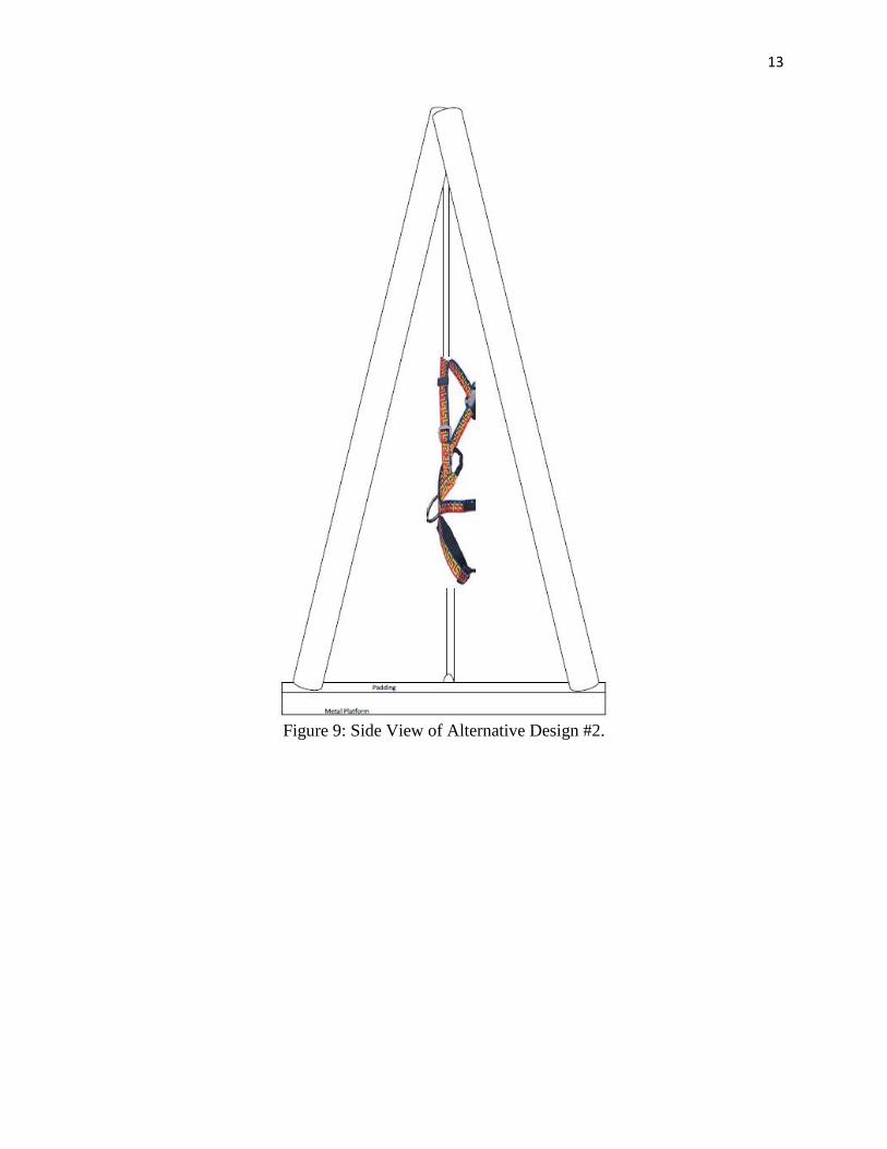
Figure 9: Side View of Alternative Design #2.
14
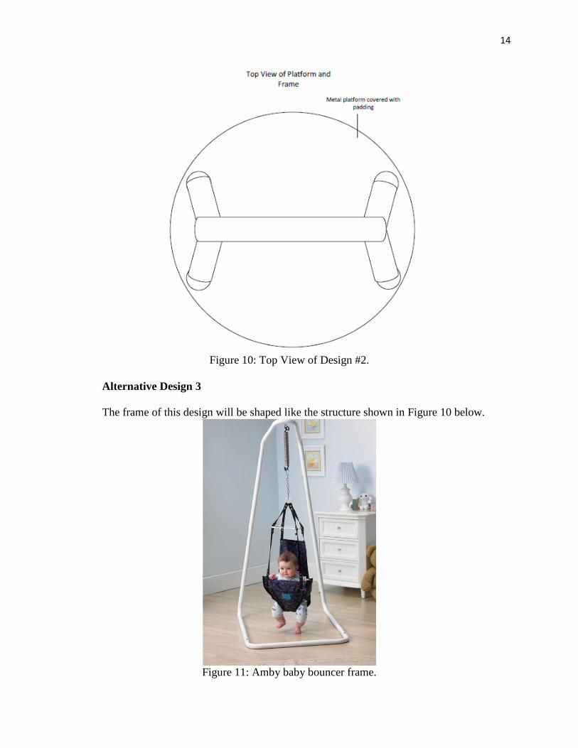
Figure 10: Top View of Design #2.
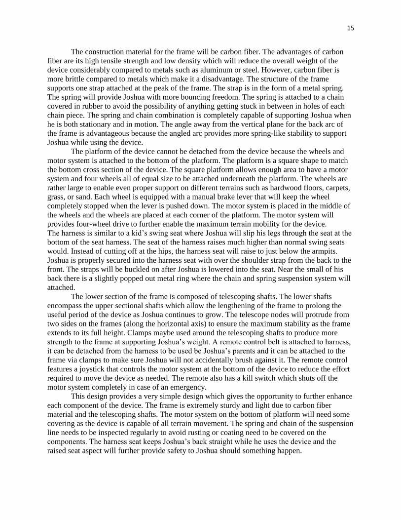
Alternative Design 3
The frame of this design will be shaped like the structure shown in Figure 10 below.
Figure 11: Amby baby bouncer frame.
15
The construction material for the frame will be carbon fiber. The advantages of carbon
fiber are its high tensile strength and low density which will reduce the overall weight of the
device considerably compared to metals such as aluminum or steel. However, carbon fiber is
more brittle compared to metals which make it a disadvantage. The structure of the frame
supports one strap attached at the peak of the frame. The strap is in the form of a metal spring.
The spring will provide Joshua with more bouncing freedom. The spring is attached to a chain
covered in rubber to avoid the possibility of anything getting stuck in between in holes of each
chain piece. The spring and chain combination is completely capable of supporting Joshua when
he is both stationary and in motion. The angle away from the vertical plane for the back arc of
the frame is advantageous because the angled arc provides more spring-like stability to support
Joshua while using the device.
The platform of the device cannot be detached from the device because the wheels and
motor system is attached to the bottom of the platform. The platform is a square shape to match
the bottom cross section of the device. The square platform allows enough area to have a motor
system and four wheels all of equal size to be attached underneath the platform. The wheels are
rather large to enable even proper support on different terrains such as hardwood floors, carpets,
grass, or sand. Each wheel is equipped with a manual brake lever that will keep the wheel
completely stopped when the lever is pushed down. The motor system is placed in the middle of
the wheels and the wheels are placed at each corner of the platform. The motor system will
provides four-wheel drive to further enable the maximum terrain mobility for the device.
The harness is similar to a kid’s swing seat where Joshua will slip his legs through the seat at the
bottom of the seat harness. The seat of the harness raises much higher than normal swing seats
would. Instead of cutting off at the hips, the harness seat will raise to just below the armpits.
Joshua is properly secured into the harness seat with over the shoulder strap from the back to the
front. The straps will be buckled on after Joshua is lowered into the seat. Near the small of his
back there is a slightly popped out metal ring where the chain and spring suspension system will
attached.
The lower section of the frame is composed of telescoping shafts. The lower shafts
encompass the upper sectional shafts which allow the lengthening of the frame to prolong the
useful period of the device as Joshua continues to grow. The telescope nodes will protrude from
two sides on the frames (along the horizontal axis) to ensure the maximum stability as the frame
extends to its full height. Clamps maybe used around the telescoping shafts to produce more
strength to the frame at supporting Joshua’s weight. A remote control belt is attached to harness,
it can be detached from the harness to be used be Joshua’s parents and it can be attached to the
frame via clamps to make sure Joshua will not accidentally brush against it. The remote control
features a joystick that controls the motor system at the bottom of the device to reduce the effort
required to move the device as needed. The remote also has a kill switch which shuts off the
motor system completely in case of an emergency.
This design provides a very simple design which gives the opportunity to further enhance
each component of the device. The frame is extremely sturdy and light due to carbon fiber
material and the telescoping shafts. The motor system on the bottom of platform will need some
covering as the device is capable of all terrain movement. The spring and chain of the suspension
line needs to be inspected regularly to avoid rusting or coating need to be covered on the
components. The harness seat keeps Joshua’s back straight while he uses the device and the
raised seat aspect will further provide safety to Joshua should something happen.
16
2.1 Optimal Design
2.1.1 Objective
The optimal design was created using different ideas from the alternative designs (shown
in the previous section of this report). It contains the best parts that will be brought together to
build one functioning device that fits within the limits of the budget and the environment in
which the jumper will be operated. The main goal is to safely allow Joshua to jump and stand in
a secure harness attached to bungee cords, which are suspended from the top of the frame. The
harness will have padding for comfort with long time use and it will be adjustable to account for
Joshua’s growth over the years.
It was decided that it would be ideal for him to have the ability to stay in this device
while also being able to move from room to room, which is why the team decided to make it
motorized. He enjoys following his family around the house, and this device will allow him to do
so while putting less stress on the bodies of his parents, who must always support him. The
motorization aspect will also permit the practice of controls for Josh to become accustomed to
using a motorized wheelchair inside and outside of his home. Josh does not frequently use his
upper body, so the jumper will encourage his use of a joystick to get from place to place.
While some would think that a tall and large structure is not convenient for around the
house, Joshua’s parents have ensured the team that they have wide hallways and doorways in
their home and would rather him be able to be mobile than to have to remain stationary in one
room in the house. The device will ideally have the ability to be compacted to be transported via
the Bouchard’s large van. The 80/20 Erector set materials for the frame provide simple
adjustments because the components can be assembled and dismantled using common tools. If
the original design was used, bulky poles would be welded into the platform, making it much
more difficult to transport the heavy mechanism.
In the following sections, the parts of the optimal design are explained thoroughly
including specifications and how the components will function in the whole system. Pictures are
incorporated to show each of the parts; some SolidWorks visuals were also produced for the
frame. Because changes have been made throughout the semester, these depictions are not as
detailed as they later will be.
2.1.2 Subunits
Control System
Transmitter
The controls that will be used in both the remote control for Josh’s parents, as well as the
platform for Josh will be custom made by Miratron Inc. The T-1 Standard Belly Pack
Transmitter is a fully customizable control system and will be used to control the movement of
the device. Two sets of controls will be designed, a simple version containing a joystick and
power switch, and a second version containing joystick controls, power switch, and emergency
kill button, to be used by Josh’s parents. The designs for the controls are pictured below in
Figures 12 and 13. Josh’s set of controls will be adapted for use in the removable control
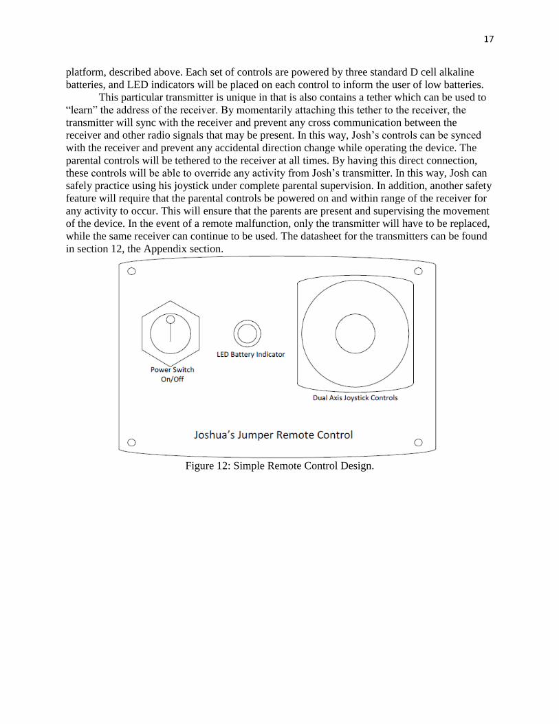
17
platform, described above. Each set of controls are powered by three standard D cell alkaline
batteries, and LED indicators will be placed on each control to inform the user of low batteries.
This particular transmitter is unique in that is also contains a tether which can be used to
“learn” the address of the receiver. By momentarily attaching this tether to the receiver, the
transmitter will sync with the receiver and prevent any cross communication between the
receiver and other radio signals that may be present. In this way, Josh’s controls can be synced
with the receiver and prevent any accidental direction change while operating the device. The
parental controls will be tethered to the receiver at all times. By having this direct connection,
these controls will be able to override any activity from Josh’s transmitter. In this way, Josh can
safely practice using his joystick under complete parental supervision. In addition, another safety
feature will require that the parental controls be powered on and within range of the receiver for
any activity to occur. This will ensure that the parents are present and supervising the movement
of the device. In the event of a remote malfunction, only the transmitter will have to be replaced,
while the same receiver can continue to be used. The datasheet for the transmitters can be found
in section 12, the Appendix section.
Figure 12: Simple Remote Control Design.
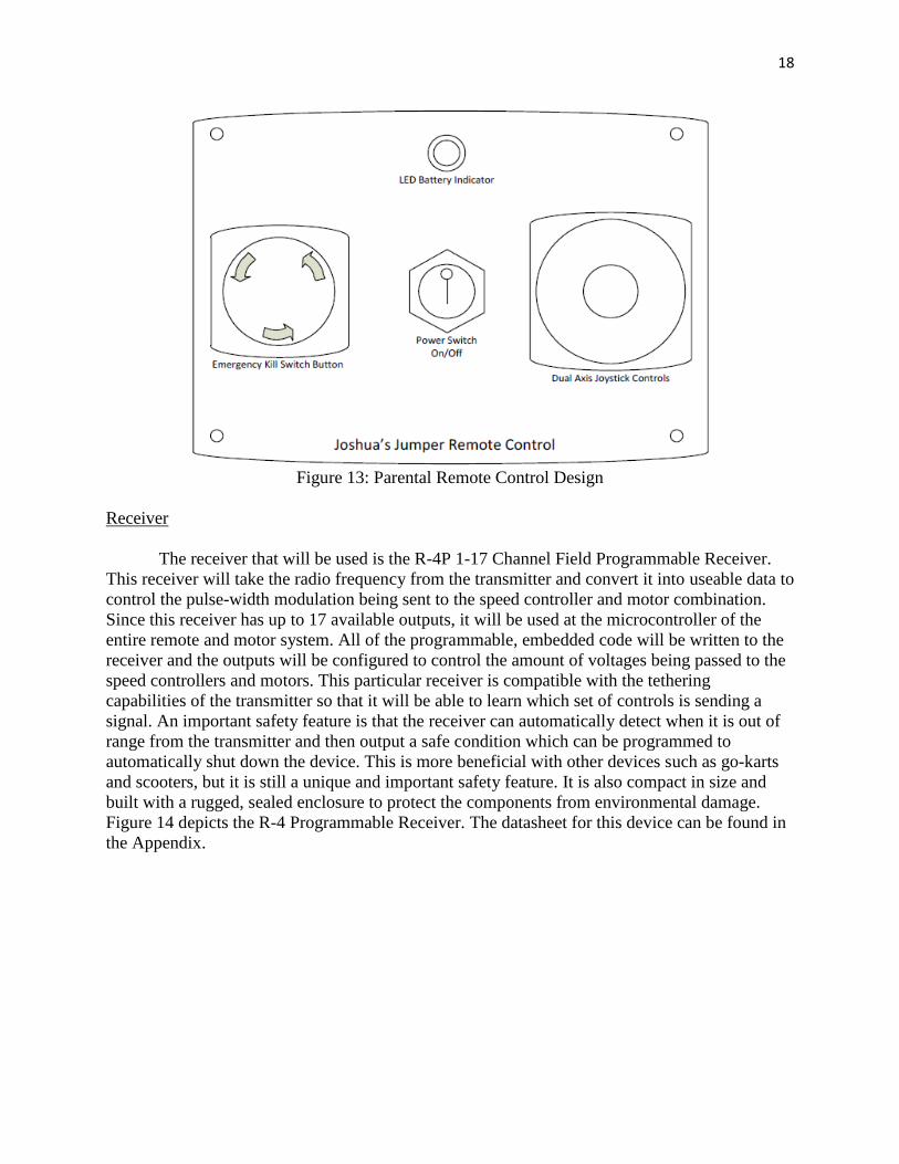
18
Figure 13: Parental Remote Control Design
Receiver
The receiver that will be used is the R-4P 1-17 Channel Field Programmable Receiver.
This receiver will take the radio frequency from the transmitter and convert it into useable data to
control the pulse-width modulation being sent to the speed controller and motor combination.
Since this receiver has up to 17 available outputs, it will be used at the microcontroller of the
entire remote and motor system. All of the programmable, embedded code will be written to the
receiver and the outputs will be configured to control the amount of voltages being passed to the
speed controllers and motors. This particular receiver is compatible with the tethering
capabilities of the transmitter so that it will be able to learn which set of controls is sending a
signal. An important safety feature is that the receiver can automatically detect when it is out of
range from the transmitter and then output a safe condition which can be programmed to
automatically shut down the device. This is more beneficial with other devices such as go-karts
and scooters, but it is still a unique and important safety feature. It is also compact in size and
built with a rugged, sealed enclosure to protect the components from environmental damage.
Figure 14 depicts the R-4 Programmable Receiver. The datasheet for this device can be found in
the Appendix.

19
Figure 14: R-4 Programmable Remote Receiver Kill Switch.
The parental remote control will feature a mushroom button kill switch. This mushroom
button will be used as a safety precaution in case of any motor or speed controller malfunction.
Once it is pressed, all outputs from the receiver will be stopped and will thus cause the device to
stop moving. The kill switch is a popular feature on the remote and will be colored red for quick
and easy recognition.
Mechanical System
Frame
Dimensions:
4 Vertical Beams: 1.5 x 1.5 x 72 inch 1515 Lite Smooth T-Slotted Aluminum Extrusions.
12 Horizontal Beams: 1.5 x 1.5 x 33 inch 1515 Lite Smooth T-Slotted Aluminum Extrusions.
1 Horizontal Crossbar: 1.5 x 1.5 x 33 inch 1501 Lite Smooth T-Slotted Aluminum Extrusions.
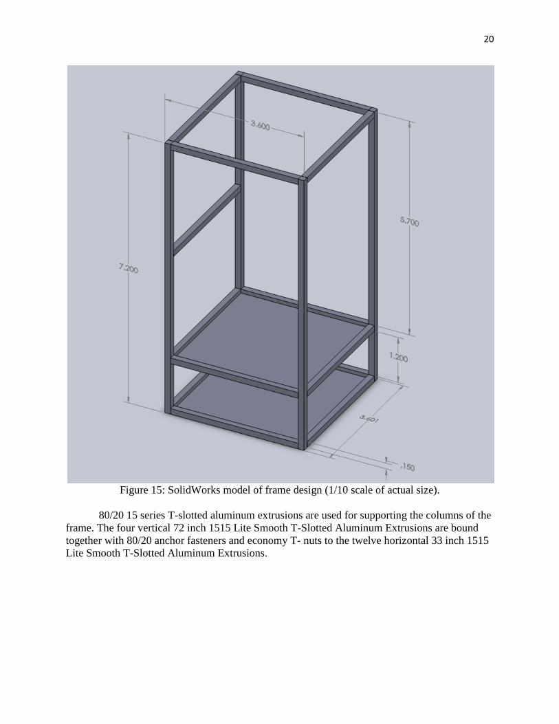
20
Figure 15: SolidWorks model of frame design (1/10 scale of actual size).
80/20 15 series T-slotted aluminum extrusions are used for supporting the columns of the
frame. The four vertical 72 inch 1515 Lite Smooth T-Slotted Aluminum Extrusions are bound
together with 80/20 anchor fasteners and economy T- nuts to the twelve horizontal 33 inch 1515
Lite Smooth T-Slotted Aluminum Extrusions.
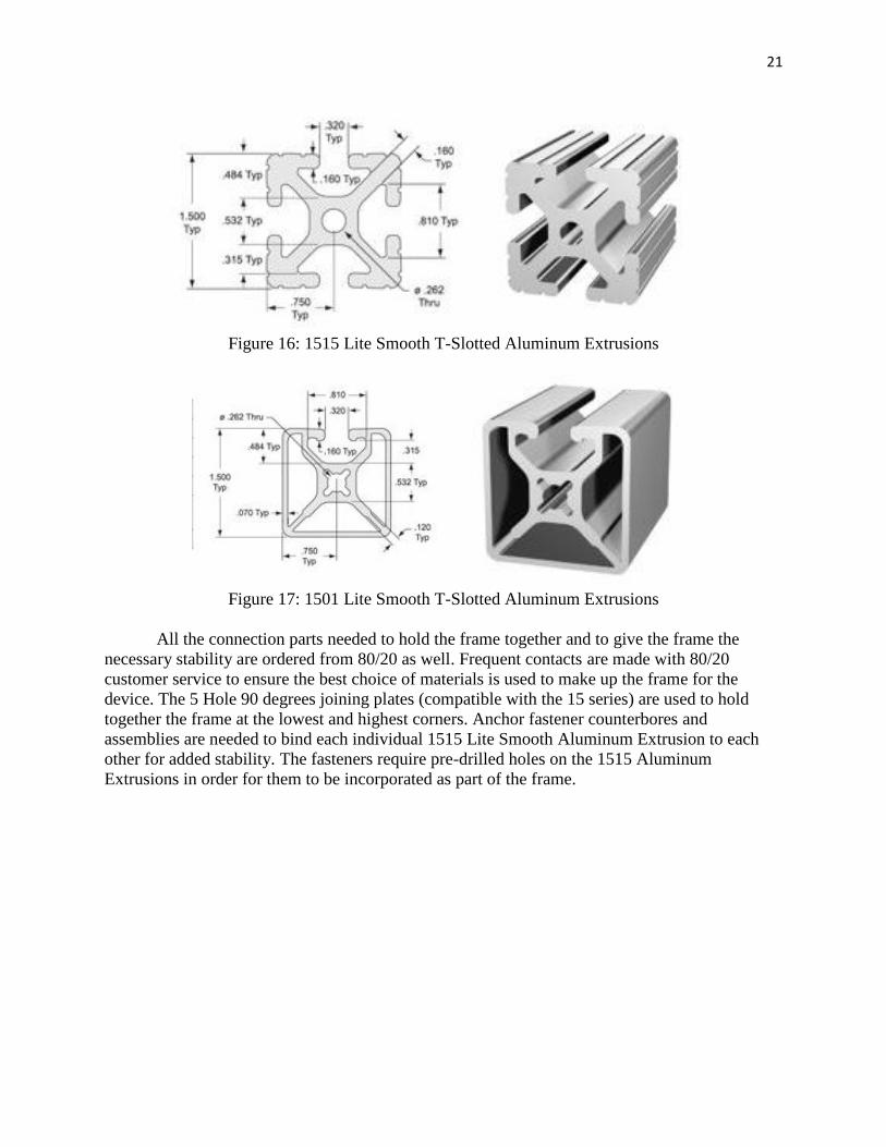
21
Figure 16: 1515 Lite Smooth T-Slotted Aluminum Extrusions
Figure 17: 1501 Lite Smooth T-Slotted Aluminum Extrusions
All the connection parts needed to hold the frame together and to give the frame the
necessary stability are ordered from 80/20 as well. Frequent contacts are made with 80/20
customer service to ensure the best choice of materials is used to make up the frame for the
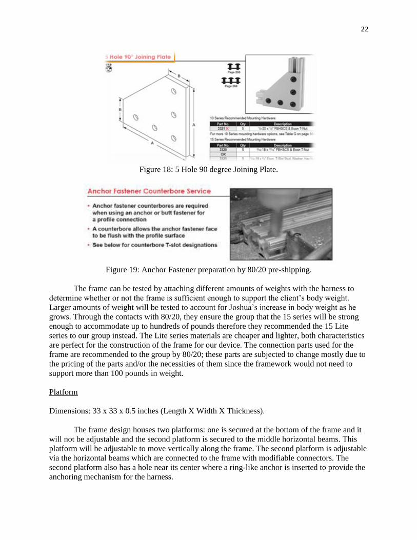
device. The 5 Hole 90 degrees joining plates (compatible with the 15 series) are used to hold
together the frame at the lowest and highest corners. Anchor fastener counterbores and
assemblies are needed to bind each individual 1515 Lite Smooth Aluminum Extrusion to each
other for added stability. The fasteners require pre-drilled holes on the 1515 Aluminum
Extrusions in order for them to be incorporated as part of the frame.
22
Figure 18: 5 Hole 90 degree Joining Plate.
Figure 19: Anchor Fastener preparation by 80/20 pre-shipping.
The frame can be tested by attaching different amounts of weights with the harness to
determine whether or not the frame is sufficient enough to support the client’s body weight.
Larger amounts of weight will be tested to account for Joshua’s increase in body weight as he
grows. Through the contacts with 80/20, they ensure the group that the 15 series will be strong
enough to accommodate up to hundreds of pounds therefore they recommended the 15 Lite
series to our group instead. The Lite series materials are cheaper and lighter, both characteristics
are perfect for the construction of the frame for our device. The connection parts used for the
frame are recommended to the group by 80/20; these parts are subjected to change mostly due to
the pricing of the parts and/or the necessities of them since the framework would not need to
support more than 100 pounds in weight.
Platform
Dimensions: 33 x 33 x 0.5 inches (Length X Width X Thickness).
The frame design houses two platforms: one is secured at the bottom of the frame and it
will not be adjustable and the second platform is secured to the middle horizontal beams. This
platform will be adjustable to move vertically along the frame. The second platform is adjustable
via the horizontal beams which are connected to the frame with modifiable connectors. The
second platform also has a hole near its center where a ring-like anchor is inserted to provide the
anchoring mechanism for the harness.
23
The platforms will be made of aluminum or potentially a different material that is
lightweight and still has enough strength to withhold the weights placed upon it. The top
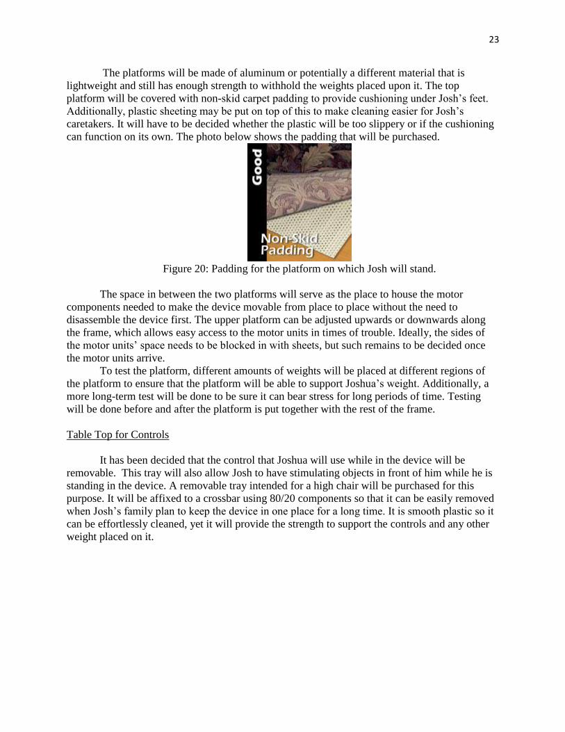
platform will be covered with non-skid carpet padding to provide cushioning under Josh’s feet.
Additionally, plastic sheeting may be put on top of this to make cleaning easier for Josh’s
caretakers. It will have to be decided whether the plastic will be too slippery or if the cushioning
can function on its own. The photo below shows the padding that will be purchased.
Figure 20: Padding for the platform on which Josh will stand.
The space in between the two platforms will serve as the place to house the motor
components needed to make the device movable from place to place without the need to
disassemble the device first. The upper platform can be adjusted upwards or downwards along
the frame, which allows easy access to the motor units in times of trouble. Ideally, the sides of
the motor units’ space needs to be blocked in with sheets, but such remains to be decided once
the motor units arrive.
To test the platform, different amounts of weights will be placed at different regions of
the platform to ensure that the platform will be able to support Joshua’s weight. Additionally, a
more long-term test will be done to be sure it can bear stress for long periods of time. Testing
will be done before and after the platform is put together with the rest of the frame.
Table Top for Controls
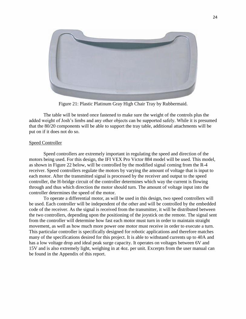
It has been decided that the control that Joshua will use while in the device will be
removable. This tray will also allow Josh to have stimulating objects in front of him while he is
standing in the device. A removable tray intended for a high chair will be purchased for this
purpose. It will be affixed to a crossbar using 80/20 components so that it can be easily removed
when Josh’s family plan to keep the device in one place for a long time. It is smooth plastic so it
can be effortlessly cleaned, yet it will provide the strength to support the controls and any other
weight placed on it.
24
Figure 21: Plastic Platinum Gray High Chair Tray by Rubbermaid.
The table will be tested once fastened to make sure the weight of the controls plus the
added weight of Josh’s limbs and any other objects can be supported safely. While it is presumed
that the 80/20 components will be able to support the tray table, additional attachments will be
put on if it does not do so.
Speed Controller
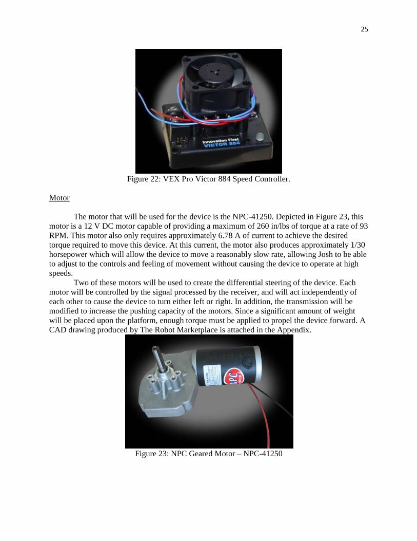
Speed controllers are extremely important in regulating the speed and direction of the
motors being used. For this design, the IFI VEX Pro Victor 884 model will be used. This model,
as shown in Figure 22 below, will be controlled by the modified signal coming from the R-4
receiver. Speed controllers regulate the motors by varying the amount of voltage that is input to
each motor. After the transmitted signal is processed by the receiver and output to the speed
controller, the H-bridge circuit of the controller determines which way the current is flowing
through and thus which direction the motor should turn. The amount of voltage input into the
controller determines the speed of the motor.
To operate a differential motor, as will be used in this design, two speed controllers will
be used. Each controller will be independent of the other and will be controlled by the embedded
code of the receiver. As the signal is received from the transmitter, it will be distributed between
the two controllers, depending upon the positioning of the joystick on the remote. The signal sent
from the controller will determine how fast each motor must turn in order to maintain straight
movement, as well as how much more power one motor must receive in order to execute a turn.
This particular controller is specifically designed for robotic applications and therefore matches
many of the specifications desired for this project. It is able to withstand currents up to 40A and
has a low voltage drop and ideal peak surge capacity. It operates on voltages between 6V and
15V and is also extremely light, weighing in at 4oz. per unit. Excerpts from the user manual can
be found in the Appendix of this report.
25
Figure 22: VEX Pro Victor 884 Speed Controller.
Motor
The motor that will be used for the device is the NPC-41250. Depicted in Figure 23, this
motor is a 12 V DC motor capable of providing a maximum of 260 in/lbs of torque at a rate of 93
RPM. This motor also only requires approximately 6.78 A of current to achieve the desired
torque required to move this device. At this current, the motor also produces approximately 1/30
horsepower which will allow the device to move a reasonably slow rate, allowing Josh to be able
to adjust to the controls and feeling of movement without causing the device to operate at high
speeds.
Two of these motors will be used to create the differential steering of the device. Each
motor will be controlled by the signal processed by the receiver, and will act independently of
each other to cause the device to turn either left or right. In addition, the transmission will be
modified to increase the pushing capacity of the motors. Since a significant amount of weight
will be placed upon the platform, enough torque must be applied to propel the device forward. A
CAD drawing produced by The Robot Marketplace is attached in the Appendix.
Figure 23: NPC Geared Motor – NPC-41250
26
Support System
Harness
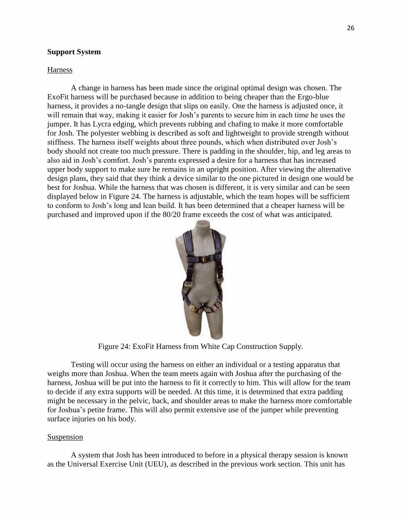
A change in harness has been made since the original optimal design was chosen. The
ExoFit harness will be purchased because in addition to being cheaper than the Ergo-blue
harness, it provides a no-tangle design that slips on easily. One the harness is adjusted once, it
will remain that way, making it easier for Josh’s parents to secure him in each time he uses the
jumper. It has Lycra edging, which prevents rubbing and chafing to make it more comfortable
for Josh. The polyester webbing is described as soft and lightweight to provide strength without
stiffness. The harness itself weights about three pounds, which when distributed over Josh’s
body should not create too much pressure. There is padding in the shoulder, hip, and leg areas to
also aid in Josh’s comfort. Josh’s parents expressed a desire for a harness that has increased
upper body support to make sure he remains in an upright position. After viewing the alternative
design plans, they said that they think a device similar to the one pictured in design one would be
best for Joshua. While the harness that was chosen is different, it is very similar and can be seen
displayed below in Figure 24. The harness is adjustable, which the team hopes will be sufficient
to conform to Josh’s long and lean build. It has been determined that a cheaper harness will be
purchased and improved upon if the 80/20 frame exceeds the cost of what was anticipated.
Figure 24: ExoFit Harness from White Cap Construction Supply.
Testing will occur using the harness on either an individual or a testing apparatus that
weighs more than Joshua. When the team meets again with Joshua after the purchasing of the
harness, Joshua will be put into the harness to fit it correctly to him. This will allow for the team
to decide if any extra supports will be needed. At this time, it is determined that extra padding
might be necessary in the pelvic, back, and shoulder areas to make the harness more comfortable
for Joshua’s petite frame. This will also permit extensive use of the jumper while preventing
surface injuries on his body.
Suspension
A system that Josh has been introduced to before in a physical therapy session is known
as the Universal Exercise Unit (UEU), as described in the previous work section. This unit has
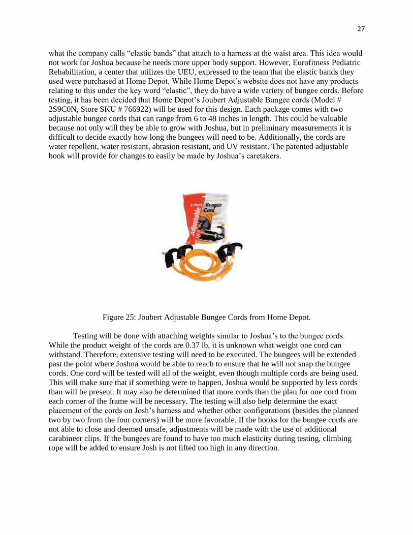
27
what the company calls “elastic bands” that attach to a harness at the waist area. This idea would
not work for Joshua because he needs more upper body support. However, Eurofitness Pediatric
Rehabilitation, a center that utilizes the UEU, expressed to the team that the elastic bands they
used were purchased at Home Depot. While Home Depot’s website does not have any products
relating to this under the key word “elastic”, they do have a wide variety of bungee cords. Before
testing, it has been decided that Home Depot’s Joubert Adjustable Bungee cords (Model #
2S9C0N, Store SKU # 766922) will be used for this design. Each package comes with two
adjustable bungee cords that can range from 6 to 48 inches in length. This could be valuable
because not only will they be able to grow with Joshua, but in preliminary measurements it is
difficult to decide exactly how long the bungees will need to be. Additionally, the cords are
water repellent, water resistant, abrasion resistant, and UV resistant. The patented adjustable
hook will provide for changes to easily be made by Joshua’s caretakers.
Figure 25: Joubert Adjustable Bungee Cords from Home Depot.
Testing will be done with attaching weights similar to Joshua’s to the bungee cords.
While the product weight of the cords are 0.37 lb, it is unknown what weight one cord can
withstand. Therefore, extensive testing will need to be executed. The bungees will be extended
past the point where Joshua would be able to reach to ensure that he will not snap the bungee
cords. One cord will be tested will all of the weight, even though multiple cords are being used.
This will make sure that if something were to happen, Joshua would be supported by less cords
than will be present. It may also be determined that more cords than the plan for one cord from
each corner of the frame will be necessary. The testing will also help determine the exact
placement of the cords on Josh’s harness and whether other configurations (besides the planned
two by two from the four corners) will be more favorable. If the hooks for the bungee cords are
not able to close and deemed unsafe, adjustments will be made with the use of additional
carabineer clips. If the bungees are found to have too much elasticity during testing, climbing
rope will be added to ensure Josh is not lifted too high in any direction.
28
3 Realistic Constraints
Economic constraints
This project has obvious economic constraints in that the budget will be fixed in order to
allow for monetary support for all of the other projects. Due to the great expense of the motor
and all of its components, it is possible that funding will not be provided for the motorization of
the device. If there is not ample room in the budget for these parts, the group will seek out other
funding or donations. Potentially, the device will be made with wheels but without motorization,
still allowing for easy movement throughout the house. This will meet the needs of the client in
that Josh will be able to stand and jump and be near his family, but it will not permit the practice
of a motorized wheelchair. Another economic constraint deals with the harness for the device.
The team hopes for there to be enough money to permit the purchase of a more expensive, yet
more durable and safer harness. If not, a cheaper, yet adequate, harness will be ordered and more
adjustments will be made to make it more comfortable and more supportive.
Environmental constraints
This device is designed for use primarily within the client’s house, and is therefore
constrained to indoor usage. Although it can be brought outdoors, the design is not intended for
extended outdoor use and many of the components may deteriorate if left exposed to the
elements. The device can certainly be waterproofed as a precaution, in case it is exposed to any
sort of moisture, in or outside of the house. The control boxes housing the electrical equipment
for the motors must also be sealed so as to prevent any build-up of dust, dirt or other debris that
might settle on the components. Also, since the motorized portion of the design is battery
powered, the device will have little impact on the environment. If any components malfunction
and need to be replaced, it is important to dispose of them properly so as to reduce the impact of
this device.
Health and Safety
Because Josh is a young boy and has these developmental issues, his health and safety are
especially important for this project. It is necessary for the team to consider every possible
movement Josh could make while in this device, in order to make sure it is safe for his use. This
includes the height and lateral distance his body could reach while jumping and moving about in
the device. It is important that his head and body cannot be injured by contact with the frame or
any other component of the jumper. The anchoring strap serves the purpose of grounding any
extreme lateral or vertical movements that Joshua might make. Also, the anchoring strap may
become a resistant adjustment strap used for resistance exercises when his legs become more fit.
The frame and platform are made of metal so trimming and dulling of the corners and edges will
be done to prevent accidents. Tapes and padding can be added as well to increase the safety of
the frame for Joshua and anyone near the proximity of the device. The openings on the poles in
the frame will be properly covered to prevent any accidents of jamming or objects getting caught
in these openings.
29
Sustainability
The frame of this device is constructed with the least amount of movable components to
lessen the possibilities of error thus increasing the sustainability of the device. The use of the
grounded poles and frame poles combination increases both the stability and sustainability of the
frame. The steel rod locking mechanism provides a longer effective time period for the device
because it allows different degrees of height adjustments to the frame. At the lowest height
setting of the pole combination, the frame poles bottom end will be at the same level of the
grounded poles which increases stability to the overall frame. The plastic sheets covering the
platform can be replaced after wear to increase the sustainability of the platform since the plastic
will protect the platform from most scratches and dents. Tapes or padding can be applied to the
edges and corners of the frame or platform to further protect the device and the users. The
bungee cords being purchased and used for this project are inexpensive and would not be a
burden to replace after wear.
The motorized portion of the device will be battery powered and it will be important for
the batteries to remain charged and ready for use. The only portion of the design that may be
difficult and more expensive to sustain would be the internal components of the motor. If the one
major component was to malfunction, it could be quite costly to replace and re-install the part. A
complete list of all components and their manufacturers will be provided in the unlikely case that
a malfunction should occur.
Manufacturability
To make fabrication of this device simpler and safer, prefabricated products are being
purchased and assembled to the specifications outlined above. These components, such as the
motors, speed controllers, harness, and bungee cords are easily accessible and can all be
purchased from online vendors. However, parts such as the platform and frame will require
custom production to account for Josh’s unique body type, as well as any growth that he might
experience. Apart from this custom modification, a vast majority of this design would be able to
be easily manufactured. If desired, it would be possible to mass produce this device and make it
available on the market.
4 Safety Issues
Safety is the primary concern when designing this device. It is essential that it remains
both safe for Josh while he is using the device as well as for those around the device while it is in
use. An obvious concern for this type of bouncing device is the stability and structure of the
frame. For this reason, the strength and rigidity of 80/20 15 series (Aluminum) was chosen to
construct the frame. By creating an adjustable frame, the frame can be raised only to the required
level, preventing any top-heavy tilting that may occur. Also, by adjusting the length of the
bungees supporting the harness, the range of bouncing can be drastically reduced, thus
preventing any chance of severe lateral movements that may cause the frame to tip. To prevent
any injury from an unlikely, but possible collision with the frame, the steel poles can be encased
in lightweight, durable foam. Also, to prevent any extreme lateral or vertical movement, the
safety strap that will run from the center of the platform to Josh’s harness will anchor him to the
center of device. This strap will be made adjustable to allow for any desired range of movement.
30
Another safety hazard is concerned with the electrical equipment used to control and
power the differential motor. To prevent any accidental interaction with the electrical and
motorized components, they will all be housed within a centralized and enclosed casing with
adequate ventilation to prevent overheating of the components and a potential fire hazard. There
will be no bare wires exposed and all components will be rated at levels higher than their
intended use to ensure that overheating of the components will not occur, and the risk of a fire
hazard is minimized.
Chemical hazards are also present due to the batteries being used to power the motor
system and transmitter and receiver. The risk of having a battery leak acid is very small, but still
a concern. It is important that the batteries be changed as needed and that they remain in dry
conditions at room temperature. In this way, any potential leakage or over heating can be
avoided, and any electrocution hazards can be avoided by covering the batteries and keeping
them removed from any moisture.
5 Impact of Engineering Solutions
The design of this assisted jumping device could have some impact on the engineering
world in a global, economic and societal context. If this device was able to become mass-
produced, it could have a great effect upon many disabled individuals, particularly those in a
situation similar to Joshua’s where they are restricted to remaining in a wheelchair and only
intermittently experience the sensation of standing and having the freedom to jump.
This device, along with multiple other devices being designed for clients with cerebral
palsy, are allowing these clients to more fully experience life and enjoy activities that most
children take for granted. By making this device available to the public, children with disabilities
will be able to have fun in a safe and controlled manner, while also working to improve their leg
strength and coordination. This device can be used as a home therapy tool to provide those with
disabilities a relatively inexpensive alternative to some therapy practices.
Globally, people would become more understanding of those with disabilities. With the
production of this device, along with multiple other devices designed to provide children with
disabilities a way to enjoy every day kid activities, more people would be exposed to the need for
such devices. From this design, other devices could be invented and modified to increase the
quality of life for many disabled people. These projects create a greater awareness of the need for
such designs and can only help to expose the world to such a great cause. More interest and
money can be generated and the research and funding can then be focused on advancing the
equipment available to those with disabilities.
6 Life-Long Learning
Many different lessons can be learned from the design of this device. From the initial
meeting with the client, this project required a great deal of research and learning about cerebral
palsy and the numerous effects it can have on an individual. Knowing the limitations of the client
was very important in beginning to design the device. By researching and learning about Josh’s
physical abilities, the team was better able to design the device in a way that will support Josh in
the proper upright, standing position, while still allowing him to strengthen his fine motor skills
through the use of the joystick controls.
31
The design of the jumper also required a lot of research into materials that could
sufficiently support a child’s weight during the bouncing motion. After researching several
materials, it was determined that the frame would be built of strong, durable steel, and a full
body, suspension harness would be used to support Josh. Researching these materials showed
how many different types of materials are available for use in numerous applications. It was
difficult deciding which materials would ultimately be used for the design, but again required the
team to research and compare materials to arrive at the best decision for the design.
The remote control and motor system has also been an area of great learning and
research. The design team has not had much prior experience in this area and have therefore been
learning and attempting to understand the detailed workings of a differential motor. From the
radio frequency communication between the transmitter and receiver, to the programming
required to correctly output the PWM signals, the remote communication has been an area of
great interest and learning. Also, converting this electrical energy to mechanical work through
the use of speed controllers and DC motors has required the team to step out of their normal
comfort zone and explore more of the engineering field that they have not yet been exposed to.
Also, especially during the design process of this project, the team members have also
acquired a much better understanding of multiple software packages available to them. Among
these packages is the SolidWorks CAD program, allowing the team to draw and visualize the
design through 3-D engineering drawings. Proficiency using Microsoft Visio and Dreamweaver
programs has also been acquired by the team members. Learning these programs and other
software packages will have long term benefits for the members, allowing them to become
proficient in similar software packages and become a well-rounded member of their future work
organization.
This project has also taught the team a great deal about working in a group setting and
time management. The deadlines for this project come quickly and often and it has been a
challenge to remain organized and meet each deadline. As the team has become more
comfortable with each other and learned one another’s strengths and weaknesses, the group
aspect of the project has become much smoother and more beneficial for meeting the required
deadlines. By assigning tasks to for each individual to complete, and then scheduling time to
compile each member’s work into the finished project, both time and work can be evenly
distributed and thus lighten the workload on each member. All of these lessons are extremely
beneficial to future success, particularly in the working world, where teamwork and time
management are essential for a successful career. This project will present the team with
numerous other challenges which must be handled. By taking the lessons the team has learned
thus far, these challenges can be overcome and ultimately the project will be completed
successfully.
7 Budget and Timeline
7.1 Budget
The budget originally presented during the proposal was $2690. However, after changes
in the design, the team projected the project would cost just under $2000 and $2000 was then
accepted by the project sponsor. Since the optimal design of this project changed after previous
reports, the parts and their prices have also changed. Additionally, the group received the news
of a donation of the transmitters and receiver from Miratron, Inc. This saved the team a lot of
money and allowed for the change in materials from aluminum poles to the 80/20 Erector Set
32
materials. The 80/20 materials will be purchased from a distributor because 80/20 does not sell
parts directly.
It is likely that the expensive ExoFit harness will be able to be purchased within the
budget, rather than a cheaper harness with extra adjustments. This will save the team time and
also provide extra comfort and safety precautions for the client’s use on Joshua’s Jumper. One
hundred dollars was originally left for other parts that may be left out or may later become
necessary for the project; however, this was taken out for us to be able to afford the new 80/20
frame and platforms.
Table 1 below shoes the parts, their more specific description, the seller of the parts, the
quantity in which they will be purchased, their unit price, shipping cost, and total cost.
Additionally, at the bottom of the table is the total without the donation from Miratron, Inc., the
grand total, and what 35% of the grand total is to show how future productions of this project
would be cheaper than this prototype. Staying under budget so far is a great accomplishment
because this project is something that has not completely been done, and many of the concepts
and parts of the project are new to the members of the team.
Part Name (Model/Description) Seller Qty Unit
Price
Shippi
ng Total Cost
Motor Dayton Gearmotor, 41 RPM, 26
Torque, 12 VDC, TENV Grainger 2 165.00 15.00 345.00
Transmitter T-1 Standard Belly Pack Transmitter Miratron 2 80.00 15.00 175.00
Receiver R-4P Field Programmable Receiver Miratron 1 40.00 10.00 50.00
Speed
Controller
IFI VEX Pro Victor 884 Speed
Controller VEX Robotics 2 99.95 8.36 208.26
Transmission Gears and Two Axles
1 100.00 15.00 115.00
Frame 80/20 Erector Set Components with
Platforms included 80/20 1 848.98
848.98
Platform
Cushion Padding Non-Skid 3 x 5 ft rectangle Rug Sale 1 25.50 18.00 43.50
Platform
Cover
Second Sight II Plastic Desk
Protector/Sheet, 19"x24"
Amazon
(Office
Quarters)
3 1.88 6.10 11.74
Small Wheels 3" Locking Swivel Caster with Plate Highland
Woodworking 2 8.50 7.99 24.99
Larger
Wheels
9 x 2-3/4" Wheelchair Tires, Saw
Tooth Tread. Pair
Edmond
Wheelchair 2 10.29 8.95 29.53
Wheel Rims Front Rim for 200 x 50mm (8" x 2")
Tires
Ebay
(tncscooters) 2 10.50 6.00 27.00
Wheel Tubes 250-4 Wheelchair Tubes, 90 degree
valve stem. Pair
Edmond
Wheelchair 1 11.25 13.50 24.75
Harness EXOFIT-Harness DBI-SALA | 9214 White Cap 1 228.37 10.00 238.37
Tray Table Rubbermaid 7815-88-PLAT Tray
(Platinum)
Newton
Distributing 1 37.12 8.88 46.00
Bungee
Chords
Joubert 2Pk 6-48 In, Adjustable
Bungee Cords Home Depot 3 3.48 - 10.44
Total Before Donation $2,198.56
GRAND TOTAL $1,973.56
35% of Grand Total $690.75
Table 1: Complete budget including shipping prices and totals for all parts expected to be
purchased.
33
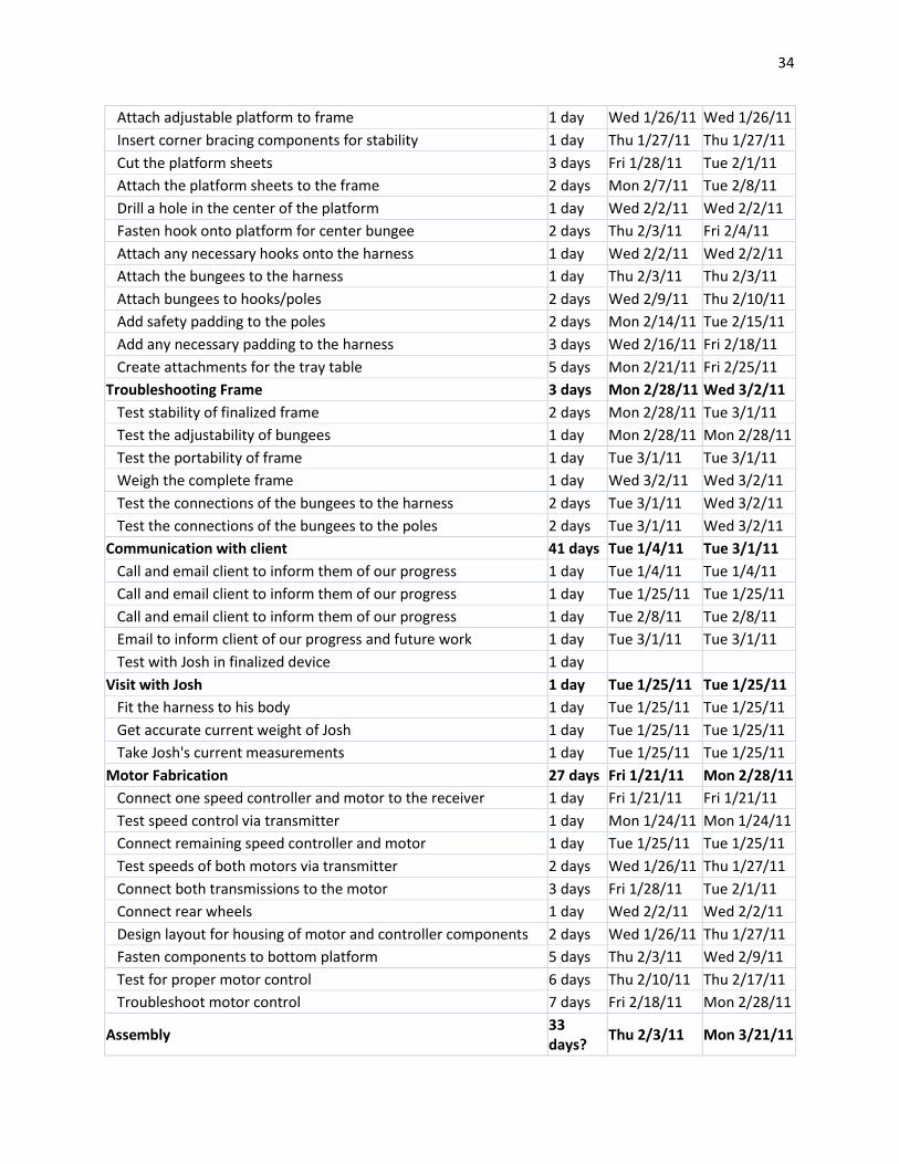
7.2 Timeline
A timeline will be used for the rest of the senior design class to keep in order the needs of
the project. Some of these tasks rely on previous jobs, so the dates of the tasks follow the
expected date of completion of the predecessors. The device is expected to be completed around
March of 2011 and the final report and presentation will then be completed in April of 2011.
Table 2 below shows the extensive lists of tasks the group will complete by the end of the spring
semester in order to accomplish the final production of Joshua’s Jumper.
Task Name Duration Start Finish
Preparation 55 days Fri 11/5/10 Thu 1/20/11
Call Miratron about controller and receiver compatibility 1 day Fri 11/5/10 Fri 11/5/10
Call Local Home Depots about small part and bungee donation 1 day Wed 11/10/10
Wed 11/10/10
Call experts to find out if the better harnesses can fit Josh's small size
1 day Thu 11/11/10 Thu 11/11/10
Practice welding metal in the machine shop 4 days Mon 1/17/11 Thu 1/20/11
Learn C Code for receiver 3 days Mon 11/15/10
Wed 11/17/10
Write C Code for receiver 7 days Thu 11/18/10 Fri 11/26/10
Checking Ordered Parts 8 days Mon 1/17/11 Wed 1/26/11
Weigh Frame Parts 2 days Mon 1/17/11 Tue 1/18/11
Test the bungee cords with various tensions and weights 1 day Wed 1/19/11 Wed 1/19/11
Measure the poles and platform 1 day Wed 1/19/11 Wed 1/19/11
Test motor for proper functioning 1 day Mon 1/24/11 Mon 1/24/11
Test voltage output of batteries 1 day Mon 1/24/11 Mon 1/24/11
Test Transmitter and Receiver Compatibility 2 days Tue 1/25/11 Wed 1/26/11
Design 18 days Mon 12/20/10
Wed 1/12/11
Design Transmission to optimize motor performance 4 days Mon 12/20/10
Thu 12/23/10
Design Receiver/Speed Controller Interface 7 days Fri 12/24/10 Mon 1/3/11
Design Speed Controller/Motor Interface 7 days Tue 1/4/11 Wed 1/12/11
CAD the changes in the frame component measurements 4 days Mon 12/20/10
Thu 12/23/10
Learn the weldments process in SolidWorks 4 days Mon 12/20/10
Thu 12/23/10
Update SolidWorks visuals of platform with dimensions after production
5 days
Finalize SolidWorks 4 days
Frame & Inner Component Fabrication 25 days Mon 1/24/11 Fri 2/25/11
Assemble bottom platform 2 days Mon 1/24/11 Tue 1/25/11
Assemble top, adjustable platform 2 days Mon 1/24/11 Tue 1/25/11
Assemble exterior rectangular frame 2 days Mon 1/24/11 Tue 1/25/11
34
Attach adjustable platform to frame 1 day Wed 1/26/11 Wed 1/26/11
Insert corner bracing components for stability 1 day Thu 1/27/11 Thu 1/27/11
Cut the platform sheets 3 days Fri 1/28/11 Tue 2/1/11
Attach the platform sheets to the frame 2 days Mon 2/7/11 Tue 2/8/11
Drill a hole in the center of the platform 1 day Wed 2/2/11 Wed 2/2/11
Fasten hook onto platform for center bungee 2 days Thu 2/3/11 Fri 2/4/11
Attach any necessary hooks onto the harness 1 day Wed 2/2/11 Wed 2/2/11
Attach the bungees to the harness 1 day Thu 2/3/11 Thu 2/3/11
Attach bungees to hooks/poles 2 days Wed 2/9/11 Thu 2/10/11
Add safety padding to the poles 2 days Mon 2/14/11 Tue 2/15/11
Add any necessary padding to the harness 3 days Wed 2/16/11 Fri 2/18/11
Create attachments for the tray table 5 days Mon 2/21/11 Fri 2/25/11
Troubleshooting Frame 3 days Mon 2/28/11 Wed 3/2/11
Test stability of finalized frame 2 days Mon 2/28/11 Tue 3/1/11
Test the adjustability of bungees 1 day Mon 2/28/11 Mon 2/28/11
Test the portability of frame 1 day Tue 3/1/11 Tue 3/1/11
Weigh the complete frame 1 day Wed 3/2/11 Wed 3/2/11
Test the connections of the bungees to the harness 2 days Tue 3/1/11 Wed 3/2/11
Test the connections of the bungees to the poles 2 days Tue 3/1/11 Wed 3/2/11
Communication with client 41 days Tue 1/4/11 Tue 3/1/11
Call and email client to inform them of our progress 1 day Tue 1/4/11 Tue 1/4/11
Call and email client to inform them of our progress 1 day Tue 1/25/11 Tue 1/25/11
Call and email client to inform them of our progress 1 day Tue 2/8/11 Tue 2/8/11
Email to inform client of our progress and future work 1 day Tue 3/1/11 Tue 3/1/11
Test with Josh in finalized device 1 day
Visit with Josh 1 day Tue 1/25/11 Tue 1/25/11
Fit the harness to his body 1 day Tue 1/25/11 Tue 1/25/11
Get accurate current weight of Josh 1 day Tue 1/25/11 Tue 1/25/11
Take Josh's current measurements 1 day Tue 1/25/11 Tue 1/25/11
Motor Fabrication 27 days Fri 1/21/11 Mon 2/28/11
Connect one speed controller and motor to the receiver 1 day Fri 1/21/11 Fri 1/21/11
Test speed control via transmitter 1 day Mon 1/24/11 Mon 1/24/11
Connect remaining speed controller and motor 1 day Tue 1/25/11 Tue 1/25/11
Test speeds of both motors via transmitter 2 days Wed 1/26/11 Thu 1/27/11
Connect both transmissions to the motor 3 days Fri 1/28/11 Tue 2/1/11
Connect rear wheels 1 day Wed 2/2/11 Wed 2/2/11
Design layout for housing of motor and controller components 2 days Wed 1/26/11 Thu 1/27/11
Fasten components to bottom platform 5 days Thu 2/3/11 Wed 2/9/11
Test for proper motor control 6 days Thu 2/10/11 Thu 2/17/11
Troubleshoot motor control 7 days Fri 2/18/11 Mon 2/28/11
Assembly 33 days?
Thu 2/3/11 Mon 3/21/11
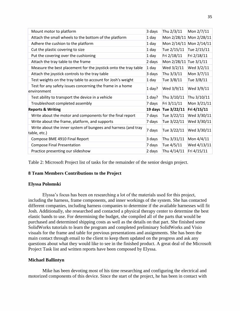
35
Mount motor to platform 3 days Thu 2/3/11 Mon 2/7/11
Attach the small wheels to the bottom of the platform 1 day Mon 2/28/11 Mon 2/28/11
Adhere the cushion to the platform 1 day Mon 2/14/11 Mon 2/14/11
Cut the plastic covering to size 1 day Tue 2/15/11 Tue 2/15/11
Put the covering over the cushioning 1 day Fri 2/18/11 Fri 2/18/11
Attach the tray table to the frame 2 days Mon 2/28/11 Tue 3/1/11
Measure the best placement for the joystick onto the tray table 1 day Wed 3/2/11 Wed 3/2/11
Attach the joystick controls to the tray table 3 days Thu 3/3/11 Mon 3/7/11
Test weights on the tray table to account for Josh's weight 1 day Tue 3/8/11 Tue 3/8/11
Test for any safety issues concerning the frame in a home environment
1 day? Wed 3/9/11 Wed 3/9/11
Test ability to transport the device in a vehicle 1 day? Thu 3/10/11 Thu 3/10/11
Troubleshoot completed assembly 7 days Fri 3/11/11 Mon 3/21/11
Reports & Writing 19 days Tue 3/22/11 Fri 4/15/11
Write about the motor and components for the final report 7 days Tue 3/22/11 Wed 3/30/11
Write about the frame, platform, and supports 7 days Tue 3/22/11 Wed 3/30/11
Write about the inner system of bungees and harness (and tray table, etc.)
7 days Tue 3/22/11 Wed 3/30/11
Compose BME 4910 Final Report 3 days Thu 3/31/11 Mon 4/4/11
Compose Final Presentation 7 days Tue 4/5/11 Wed 4/13/11
Practice presenting our slideshow 2 days Thu 4/14/11 Fri 4/15/11
Table 2: Microsoft Project list of tasks for the remainder of the senior design project.
8 Team Members Contributions to the Project
Elyssa Polomski
Elyssa’s focus has been on researching a lot of the materials used for this project,
including the harness, frame components, and inner workings of the system. She has contacted
different companies, including harness companies to determine if the available harnesses will fit
Josh. Additionally, she researched and contacted a physical therapy center to determine the best
elastic bands to use. For determining the budget, she compiled all of the parts that would be
purchased and determined shipping costs as well as the details on that part. She finished some
SolidWorks tutorials to learn the program and completed preliminary SolidWorks and Visio
visuals for the frame and table for previous presentations and assignments. She has been the
main contact through email to the client to keep them updated on the progress and ask any
questions about what they would like to see in the finished product. A great deal of the Microsoft
Project Task list and written reports have been composed by Elyssa.
Michael Ballintyn
Mike has been devoting most of his time researching and configuring the electrical and
motorized components of this device. Since the start of the project, he has been in contact with
36
Miratron, Inc. With the help of Miratron, he has helped to design and configure both of the
transmitters and the receiver that will be used to control the device. He has also been responsible
for finding the appropriate speed controllers and motors that will be capable of powering the
device. After researching several models and reviewing numerous data sheets, the current speed
controller and motor were selected and submitted for purchase. Mike has also assisted in the
development of the frame, particularly the area that will house the electronic components. Mike
has been a large contributor for the organization and completion of reports and assignments
(Microsoft Project task list, Visio visuals, etc.) during the semester.
Tianyi Xu
Tianyi’s area of focus for the project lies with the frame design and construction. After
the general idea for the frame was discussed by the group, he worked to design the most viable
frame needed for the device. He reviewed the 80/20 catalog and picked out what were believed
to be the best parts needed for the frame design. Tianyi is in contact with Ryan Zettle from 80/20
to choose and purchase the frame components. He is responsible for keeping up the group
website on the UConn BME page. Tianyi uses Dreamweaver regularly to post new documents
and update the site as needed. He is still in the process of learning the Dreamweaver software so
as to more effectively organize the website. Tianyi has made several SolidWorks drawings for
the evolution of the frame design.
9 Conclusion
The overall objective of this project is to provide our client Joshua, who has been
diagnosed with cerebral palsy, the opportunity to have more freedom to remain in the standing
position. Currently, Joshua is wheelchair bound and does not have a device that gives him the
ability to stand and jump for extended periods of time. Normally, the only time he experiences
the feeling of standing and jumping is when held by his parents. Since his parents are unable to
support his weight for extended periods of time, this device will alleviate the stresses put on their
bodies, and allow them to do other tasks while Josh is safely supported in the device. The family
also desired that this device be motorized in the hopes that Josh can use it as a training tool to
prepare him for a motorized wheelchair.
Currently, the only devices that support this type of activity are primarily meant for
infants. None of these devices are motorized and cannot support a child with a weight and height
similar to Josh. This device will not only be able to support Josh now, but will also be adjustable
to account for any growth he may have over the following years. It will be structurally sound and
allow for disassembly if the family wishes to take it with them on trips. Being motorized, this
device will also allow Josh’s parents an easier method with which to transport him about the
house, while allowing Josh the freedom to remain in the standing position.
This project will be incredibly beneficial to Josh and his family. He will be able to use
this device as a means to both strengthen his legs and learn how to operate a joystick-controlled,
motorized device. It will provide him with the freedom to do things every child does with little
aid from his parents. Throughout the process, the team will be able to enhance their problem
solving and design related skills and will work diligently to ensure the finalized device
accomplishes this objective.
37
10 References
[1] “THERASUIT / Universal Exercise Unit.” EuroFitnessRehab.com. Accessed on December 1
2010. <http://www.eurofitnessrehab.com/therasuit_universal_exercise_unit>.
[2] Morgan Templeton, Mike Fitzpatrick, Marek Wartenberg. University of Connecticut. NSF
2010 Engineering Senior Design Projects to Aid Persons with Disabilities. Accessed on October
9 2010. <http://www.bme.uconn.edu/sendes/Spring10/Team5/Optimal%20Design.pdf>.
[3] “Programming – Differential Drive” Society of Robots. Accessed on October 9 2010.
<http://www.societyofrobots.com/programming_differentialdrive.shtml>.
[4] “Radio Remote Controls” Miratron. Accessed on October 9 2010.
<http://www.miratron.com/radio.html>.
[5] “IFI Robotics Speed Controllers” The Robot MarketPlace. Accessed on October 17 2010. <
http://www.robotmarketplace.com/products/IFI-V884.html>.
[6] Kristie Astoria, Farrukh Rahman, Nathan Storie. University of Connecticut. NSF 2010
Engineering Senior Design Projects to Aid Persons with Disabilities. Accessed on October 4
2010. <http://www.bme.uconn.edu/sendes/Spring10/Team4/optimal.pdf>.
[7] “EXOFIT-HARNESS.” White Cap Construction Company. Accessed on October 4 2010.
<http://www.whitecap.com/dbi_sala/9214/EXOFIT_HARNESS>.
[8] “JOUBERT Adjustable Bungee Cords (2-Pack).” Homer TLC, Inc. Accessed on October 4
2010. <http://www.homedepot.com/h_d1/N-5yc1vZ1xga/R-
100401412/h_d2/ProductDisplay?langId=-1&storeId=10051&catalogId=10053>.
11 Acknowledgements
- Dr. Enderle- for obtaining funding for this project and for meeting with us and suggesting
ideas.
- Rod Seely (Miratron, Inc.)- for donating the transmitters and receiver and assisting in the
programming of these contraptions.
- The Bouchard family- for coordinating meetings and corresponding via telephone and
email with us and giving input as to what they wanted from the project.
- Marek Wartenberg- for helping us with ideas, advising us, and answering any questions
we have.
- Ryan Zettle (80/20 Inc.)- for assisting us with the proper component selection and
ordering process.
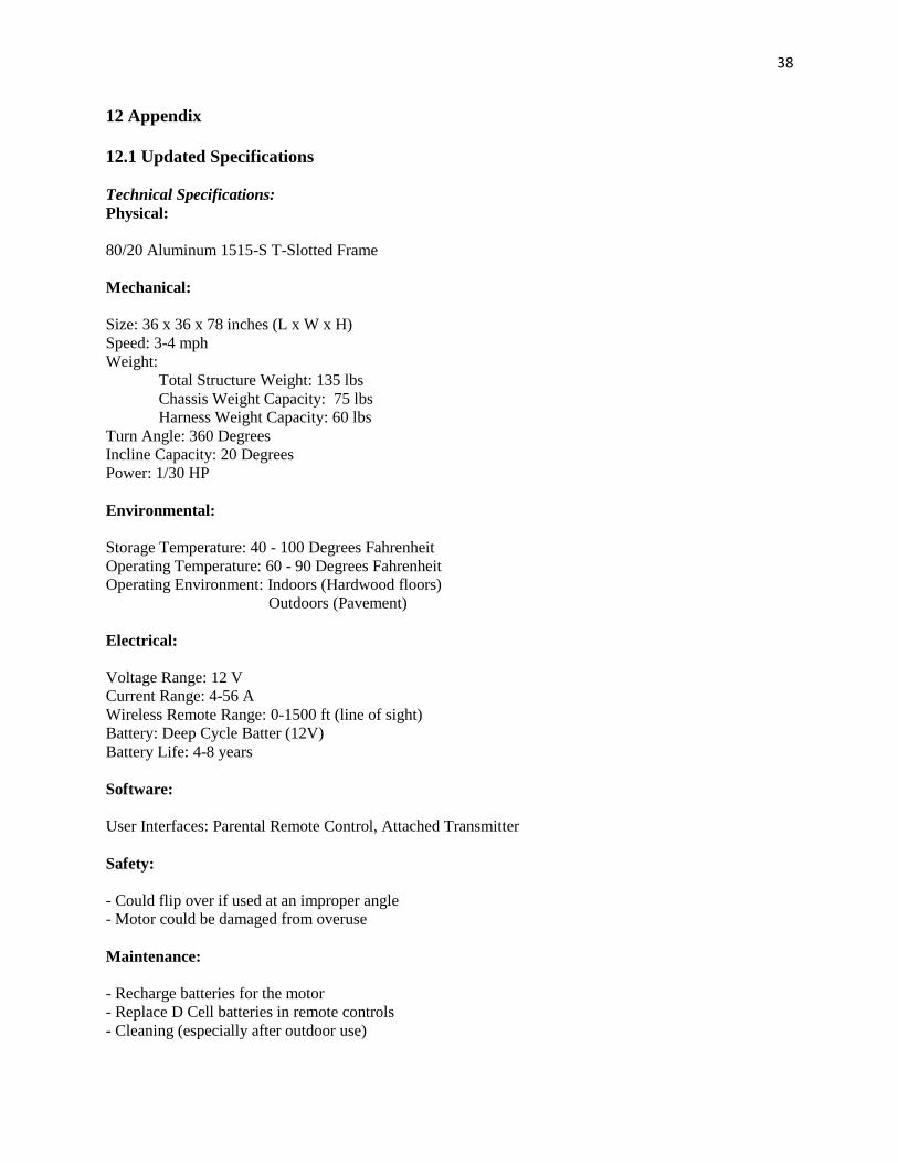
38
12 Appendix
12.1 Updated Specifications
Technical Specifications:
Physical:
80/20 Aluminum 1515-S T-Slotted Frame
Mechanical:
Size: 36 x 36 x 78 inches (L x W x H)
Speed: 3-4 mph
Weight:
Total Structure Weight: 135 lbs
Chassis Weight Capacity: 75 lbs
Harness Weight Capacity: 60 lbs
Turn Angle: 360 Degrees
Incline Capacity: 20 Degrees
Power: 1/30 HP
Environmental:
Storage Temperature: 40 - 100 Degrees Fahrenheit
Operating Temperature: 60 - 90 Degrees Fahrenheit
Operating Environment: Indoors (Hardwood floors)
Outdoors (Pavement)
Electrical:
Voltage Range: 12 V
Current Range: 4-56 A
Wireless Remote Range: 0-1500 ft (line of sight)
Battery: Deep Cycle Batter (12V)
Battery Life: 4-8 years
Software:
User Interfaces: Parental Remote Control, Attached Transmitter
Safety:
- Could flip over if used at an improper angle
- Motor could be damaged from overuse
Maintenance:
- Recharge batteries for the motor
- Replace D Cell batteries in remote controls
- Cleaning (especially after outdoor use)
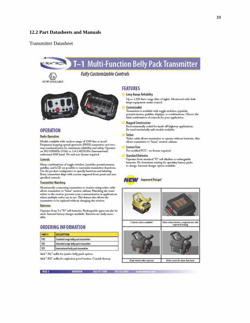
39
12.2 Part Datasheets and Manuals
Transmitter Datasheet

40
Radio Receiver Datasheet
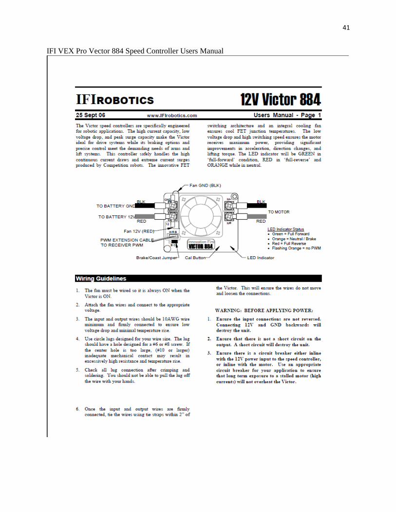
41
IFI VEX Pro Vector 884 Speed Controller Users Manual
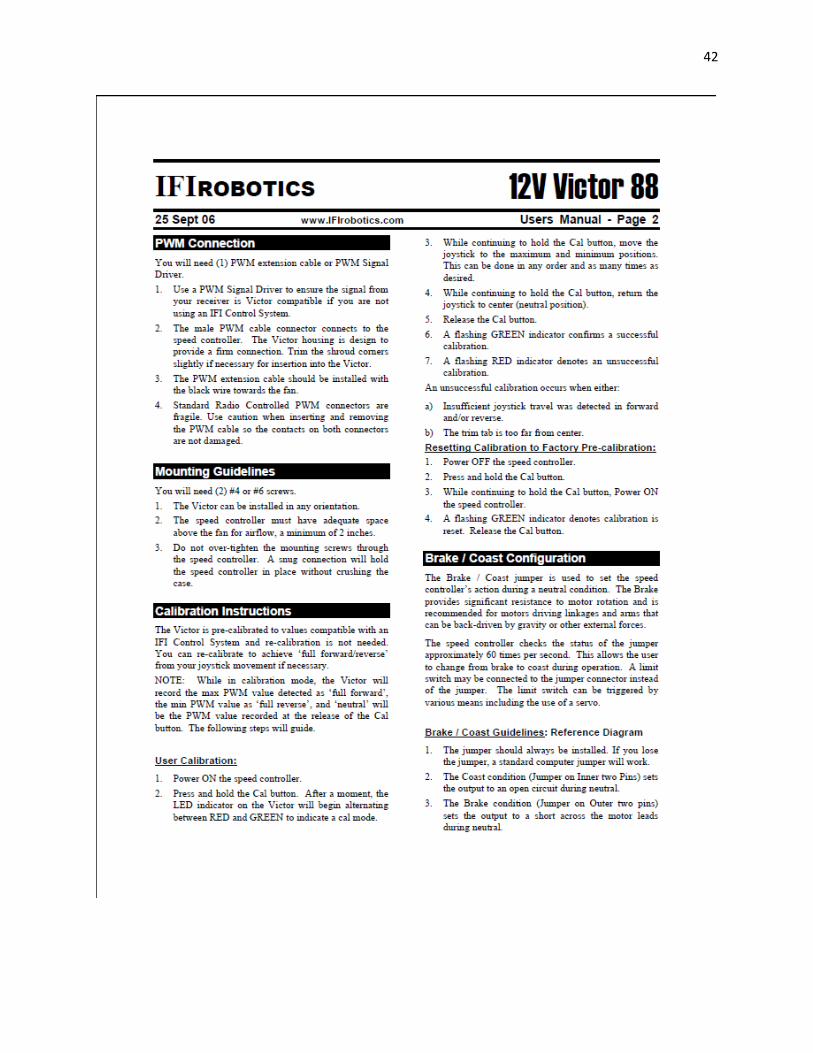
42
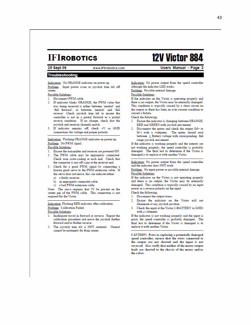
43
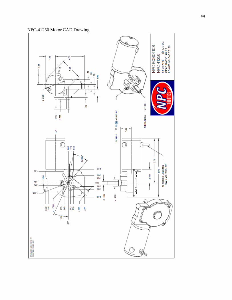
44
NPC-41250 Motor CAD Drawing
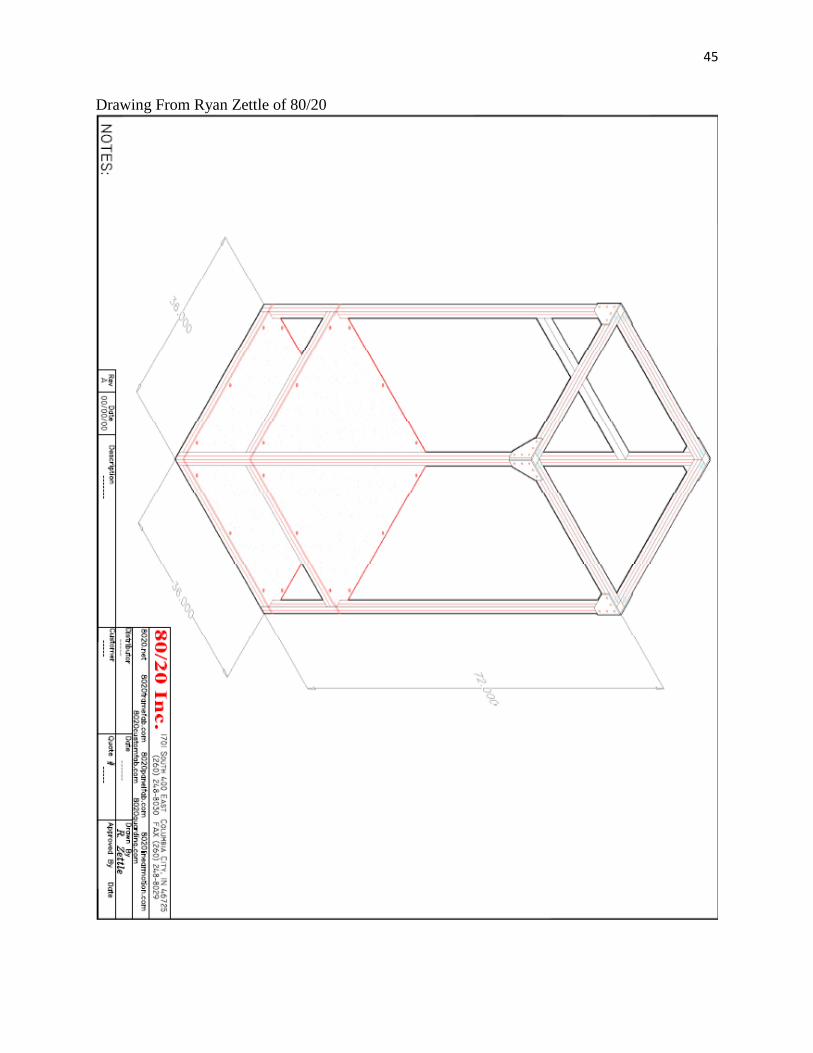
45
Drawing From Ryan Zettle of 80/20
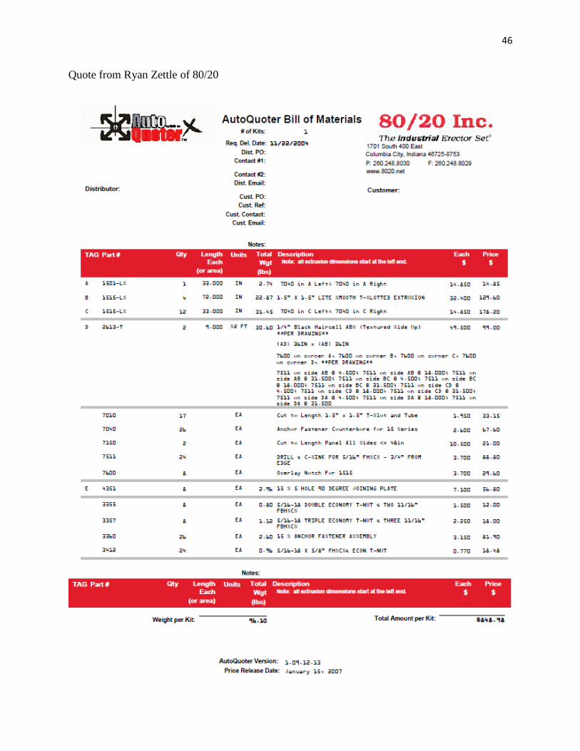
46
Quote from Ryan Zettle of 80/20