Embed Size (px)
Citation preview
Product Data Sheet00813-0100-4716, Rev GAJuly 2003 Rosemount 3095MV
www.rosemount.com
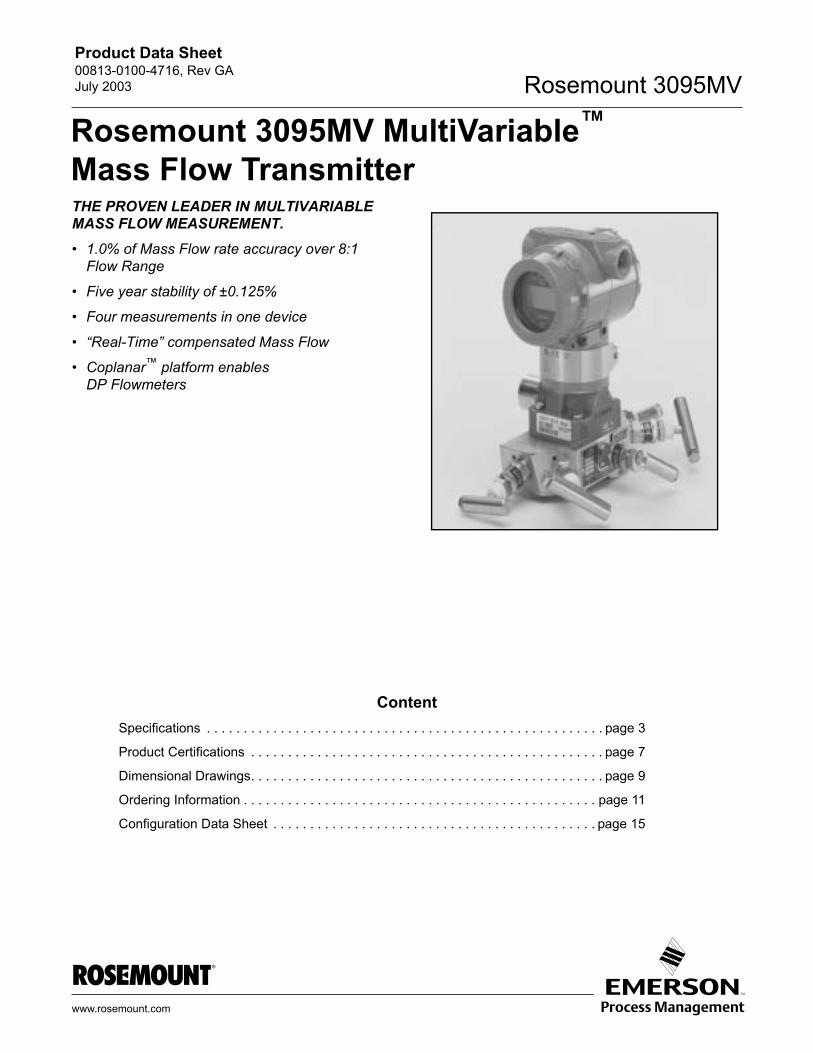
THE PROVEN LEADER IN MULTIVARIABLE MASS FLOW MEASUREMENT. 1.0% of Mass Flow rate accuracy over 8:1
Flow Range
Five year stability of ±0.125%
Four measurements in one device
Real-Time compensated Mass Flow
Coplanar platform enables DP Flowmeters
ContentSpecifications . . . . . . . . . . . . . . . . . . . . . . . . . . . . . . . . . . . . . . . . . . . . . . . . . . . . . . page 3
Product Certifications . . . . . . . . . . . . . . . . . . . . . . . . . . . . . . . . . . . . . . . . . . . . . . . . page 7
Dimensional Drawings. . . . . . . . . . . . . . . . . . . . . . . . . . . . . . . . . . . . . . . . . . . . . . . . page 9
Ordering Information . . . . . . . . . . . . . . . . . . . . . . . . . . . . . . . . . . . . . . . . . . . . . . . . page 11
Configuration Data Sheet . . . . . . . . . . . . . . . . . . . . . . . . . . . . . . . . . . . . . . . . . . . . page 15
Rosemount 3095MV MultiVariable Mass Flow Transmitter
Product Data Sheet00813-0100-4716, Rev GA
July 2003Rosemount 3095MV
2
The Leader in Multivariable Mass Flow Measurement.Rosemount delivers a tradition of excellence and technology leadership, featuring the state-of-the-art Rosemount 3095MV Multivariable Mass Flow transmitter. The Rosemount 3095MV delivers four measurements from one coplanar device with unmatched operating performance, including dynamically compensated mass flow. Engineered to combine best products with best installation practices, the fully compensated Rosemount 3095MV enables a complete offering of DP Flowmeters.
1.0% of Mass Flow rate accuracy over 8:1 Flow RangeEnabled by superior sensor technology and engineered for optimal flow performance, the Rosemount 3095MV delivers unprecedented ±0.075% reference accuracy, resulting in mass flow accuracy of ±1.0% over 8:1 flow range. Superior performance means reduced variability and improved plant safety.
Five year stability of ±0.125%Through aggressive testing, the Rosemount 3095MV has proven its ability to maintain unprecedented performance under the most demanding conditions. Superior transmitter stability decreases calibration frequency for reduced maintenance and operation costs.
Four measurements in one deviceThe advanced Rosemount 3095MV measures three process variables simultaneously and dynamically calculates fully compensated mass flow. One transmitter means reduced process penetrations, inventory and installation costs.
Real-Time compensated Mass FlowFully compensated mass flow reduces sources of traditional DP flow uncertainty. Rosemount 3095MV calculates Mass Flow by measuring process pressure and temperature to perform real-time calculation of all flow equation parameters including density, viscosity, velocity, Reynolds number, beta ratio, discharge coefficient, velocity of approach, and the gas expansion factor. Superior flow calculations yield more accurate measurements to reduce variability and increase profitability.
Coplanar platform enables DP FlowmetersThe flexible coplanar platform allows integration with the complete offering of Rosemount primary elements for any flow application. The solution arrives factory calibrated, pressure-tested, and ready to install right out of the box. Only Rosemount has a scalable coplanar transmitter design to reduce engineering and inventory costs.
Rosemount® Pressure SolutionsRosemount 3051S Series of Instrumentation
Scaleable pressure, flow and level measurement solutions improve installation and maintenance practices. See product data sheet 00813-0100-4801.
Rosemount 305 and 306 Integral Manifolds
Factory-assembled, calibrated and seal-tested manifolds reduce on-site installation costs. See product data sheet 00813-0100-4733.
Rosemount 1195 Integral Orifice Plate and ProPlate/Mass ProPlate Flowmeters
Convenient ready-to-install assembly designed for small-bore flow measurement of any clean gas, liquid, or vapor. See product data sheet 00813-0100-4686.
Annubar® Flowmeter Series
A series of highly accurate and repeatable insertion-type flowmeters available in 2-in. to 72-in. (50.8 to 1829 mm) line sizes. See product data sheet 00813-0100-4809.
Rosemount 405 Compact Orifice
A wafer style primary element with an integral three-valve manifold. See product data sheet 00813-0100-4810.
Product Data Sheet00813-0100-4716, Rev GAJuly 2003
3
Rosemount 3095MV
Specifications
FUNCTIONAL SPECIFICATIONSServiceGas, liquid, or steam
Differential Sensor
LimitsCode 1: 0 to 25 inH2O (0 to 0,062 bar)Code 2: 250 to 250 inH2O (0,622 to 0,622 bar)Code 3: 1000 to 1000 inH2O (2,49 to 2,49 bar)
Absolute Sensor
LimitsCode 3: 0.5 to 800 psia (0,0344 to 55,2 bar)Code 4: 0.5 to 3,626 psia (0,0344 to 250 bar)
Gage Sensor
LimitsCode C: 0800 psig (055,2 bar)Code D: 03,626 psig (0250 bar)
Temperature Sensor
Process Temperature Range150 to 1500 °F (101 to 816 °C)
Fixed Temperature Range459 to 3500 °F (273 to 1927 °C)
Overpressure Limit0 psia to two times the absolute pressure sensor range with a maximum of 3,626 psia (250 bar).
Static Pressure LimitOperates within specifications between static line pressures of 0.5 psia and the URL of the absolute pressure sensor.
Configuration:
HART Communicator Performs traditional Smart transmitter functions
PC-Based Engineering Assistance (EA) software package Contains built-in physical property database Enables flow configuration, maintenance, and diagnostic
functions
Primary Elements:Supports over 25 different primary elements including:
Physical Properties Database: Maintained in Engineering Assistant Software Configurator Applicable physical properties for over 110 fluids Natural gas per AGA Steam and water per ASME Other database fluids per American Institute of
Chemical Engineers (AIChE) Optional custom entry
OutputTwo-wire 420 mA, user-selectable for DP, AP, GP, PT, mass flow, or totalized flow. Digital HART protocol superimposed on 420 mA signal, available to any host that conforms to the HART protocol.
Power SupplyExternal power supply required. Transmitter operates on terminal voltage of 1155 V dc.
Zero SuppressionCan be set anywhere within the sensor limits as long as the span is greater than or equal to the minimum span, the lower range value does not exceed the lower range limit, and the upper range value does not exceed the upper range limit.
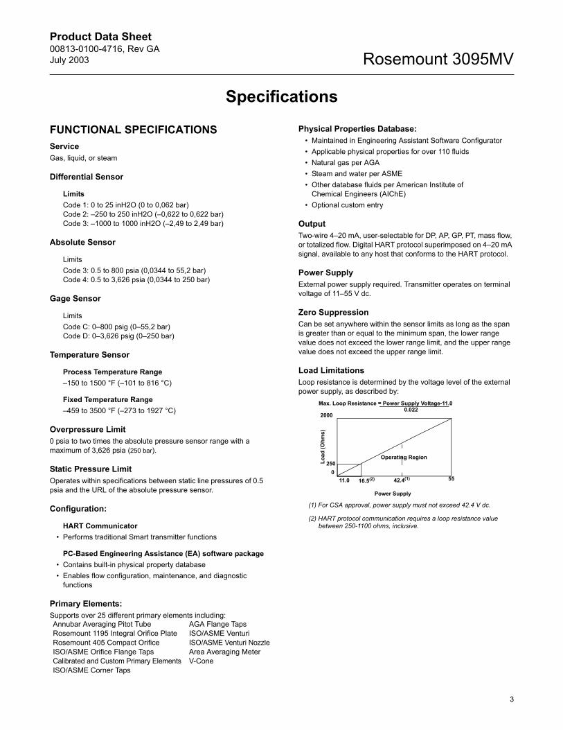
Load LimitationsLoop resistance is determined by the voltage level of the external power supply, as described by:
Annubar Averaging Pitot Tube AGA Flange TapsRosemount 1195 Integral Orifice Plate ISO/ASME VenturiRosemount 405 Compact Orifice ISO/ASME Venturi NozzleISO/ASME Orifice Flange Taps Area Averaging MeterCalibrated and Custom Primary Elements V-ConeISO/ASME Corner Taps
Max. Loop Resistance = Power Supply Voltage-11.00.022
2000
Load
(Ohm
s)
011.0 42.4(1) 55
Operating Region
(1) For CSA approval, power supply must not exceed 42.4 V dc.
(2) HART protocol communication requires a loop resistance value between 250-1100 ohms, inclusive.
Power Supply
250
16.5(2)
Product Data Sheet00813-0100-4716, Rev GA
July 2003Rosemount 3095MV
4
Temperature Limits
Process (at transmitter isolator flange for atmospheric pressures and above)Silicone fill: 40 to 250 °F (40 to 121 °C)Inert fill: 0 to 185 °F (18 to 85 °C)(Process temperature above 185 °F (85 °C) require derating the ambient limits by a 1.5:1 ratio.)
Ambient:-40 to 185 °F (-40 to 85 °C)with integral meter: -4 to 175 °F (-20 to 80 °C)
Storage:-50 to 230 °F (-46 to 110 °C)with integral meter: -40 to 185 °F (-40 to 85 °C)
Humidity Limits0100% relative humidity
Failure Mode AlarmIf self-diagnostics detect a non-recoverable transmitter failure, the analog signal will be driven either below 3.75 mA or above 21.75 mA to alert the user. High or low alarm signal is user-selectable by internal jumper.
Turn-on TimeDigital and analog measured variables will be within specifications 710 seconds after power is applied to transmitter.Digital and analog flow output will be within specifications 1014 seconds after power is applied to transmitter.
DampingResponse to step input change can be user-selectable from 0 to 29 seconds for one time constant.
Steam Flow Calculations: Steam densities calculated per ASME steam tables. Saturated steam configurable using static pressure based
density calculations.
Natural Gas Flow Calculations Flow calculations per 1992 AGA (American Gas Association)
Report No 3 or ISO-5167 (2003). Compressibilty Calculations per AGA Report No 8 or
ISO-12213.
PERFORMANCE SPECIFICATIONS (Zero-based spans, reference conditions, silicone oil fill, 316 SST isolating diaphragms, 420 mA analog output.)
Specification ConformanceThe Rosemount 3095MV maintains a specification conformance of at least 3.
Mass FlowFully compensated for pressure, temperature, density, viscosity gas expansion, discharge coefficient, and thermal correction variances over operating range.
Qm=NCdEY1d2DP(p)1/2.
Mass Flow Reference Accuracy±1.0% of Mass Flow Rate over 8:1 flow range(64:1 DP range) for liquids and gases
Totalized Mass Flow ±1.0% of Total Mass Flow
NOTE:Assume 64:1 DP range for liquids and gases.
(Uncalibrated differential producer (Orifice) installed per ASME MFC3M or ISO 5167-1. Uncertainties for discharge coefficient, producer bore, tube diameter, and gas expansion factor defined in ASME MFC3M or ISO 5167-1. Density uncertainty of 0.1%. Differential pressure calibrated at up to 1/10th full scale for optimum flow accuracy/rangeability.)
Differential Pressure (DP)Range 100.5 to 025 inH2O (00,0344 to 00,0623 bar) (50:1 rangeability is allowed)
Range 202.5 to 0250 inH2O (06,22 to 0622,7 mbar) (100:1 rangeability is allowed)
Range 3010 to 01000 inH2O (024,9 to 02490,9 mbar) (100:1 rangeability is allowed)
Reference Accuracy (including Linearity, Hysteresis, Repeatability)
Range 2-3±0.075% of span for spans from 1:1 to 10:1 of URLFor rangedowns greater than 10:1 of URL,
Range 1±0.10% of span for spans from 1:1 to 15:1 of URLFor rangedowns greater than 15:1 of URL,
Ambient Temperature Effect per 50 °F (28 °C)
Range 2-3±(0.025% of URL + 0.125% of span) for spans from 1:1 to 30:1±(0.035% of URL 0.175% of span) for spans from 30:1 to 100:1
Range 1±(0.20% of URL + 0.25% of span) for spans from 1:1 to 30:1±(0.24% of URL +0.15% of span) for spans from 30:1 to 50:1
% of Span0.025 0.005 URLSpan---------------
+Accuracy =
% of Span0.025 0.005 URLSpan---------------
+Accuracy =
Product Data Sheet00813-0100-4716, Rev GAJuly 2003
5
Rosemount 3095MV
Static Pressure Effects
Range 2-3Zero error = ±0.05% of URL per 1,000 psi (68,9 bar)Span error = ±0.20% of reading per 1,000 psi (68,9 bar)
Range 1Zero error = ±0.05% of URL per 800 psi (55,1 bar)Span error = ±0.40% of reading per 800 psi (55,1 bar)
DP Stability
Ranges 2-3±0.125% URL for 5 years for 75°F (24°C)±50°F (28°C) ambient temperature changes, and up to 1000 psi (6,9MPa) line pressure.
Range 1±0.2% of URL for 1 year
Absolute/Gage PressureRange 3 (absolute)/Range C (gage)08 to 0800 psia (00,55 to 055,1 bar)(100:1 rangeability is allowed)
Range 4 (absolute) /Range D (gage)036.26 to 03,626 psia (02,5 to 0250 bar) (100:1 rangeability is allowed)
Reference Accuracy(including Linearity, Hysteresis, Repeatability)±0.075% of span for spans from 1:1 to 6:1 of URLFor rangedowns greater than 6:1 of URL,
Ambient Temperature Effect per 50 °F (28 °C)±(0.050% of URL + 0.125% of span) spans from 1:1 to 30:1±(0.060% of URL 0.175% of span) spans from 30:1 to 100:1
Stability±0.125% URL for 5 years for 75°F (24°C)±50°F (28°C) ambient temperature changes, and up to 1000 psi (6,9MPa) line pressure.
Process Temperature (PT)Specification for process temperature is for the transmitter portion only. Sensor errors caused by the RTD are not included. The transmitter is compatible with any PT100 RTD conforming to IEC 751 Class B, which has a nominal resistance of 100 ohms at 0 °C and ∝ = 0.00385. Examples of compatible RTDs include the Rosemount Series 68 and 78 RTD Temperature Sensors.
RTD Range150 to 1,500 °F (101 to 816 °C)
PT Accuracy(including Linearity, Hysteresis, Repeatability)
For 12 and 24 ft. Cables±1.0 °F (0.56 °C) for process temperatures from 150 to 1200 °F (101to 649 °C)For process temperatures above1200 °F (649 °C), add ±1.0 °F (0.56 °C) per 100 °F (38 °C)
For 75 ft. cables:±2.0 °F (1.12 °C) for process temperatures from150 to 1200 °F (101 to 649 °C)For process temperatures above 1200 °F (649 °C),add ±1.0 °F (0.56 °C) per 100 °F (38 °C)
PT Stability±1.0 °F (0.56 °C) for 12 months
PHYSICAL SPECIFICATIONSSecurity
Transmitter security jumper mounted on electronics board, when enabled prevents changes to transmitter configuration.
User Engineering Assistant provides two levels of optional password security
Electrical Connections½14 NPT, M20 1.5 (CM20), PG-13.5
RTD Process Temperature Input100-ohm platinum RTD per IEC-751 Class B
Process ConnectionsTransmitter: ¼18 NPT on 21/8-in. centers 1/214 NPT on 2-, 21/8-, or 21/4-in. centers with optional flange adaptersRTD: RTD dependent.
Process Wetted Parts
Isolating Diaphragms316L SST or Hastelloy C-276®. CF-8M (last version of 316 SST, material per ASTM-A743)
Drain/Vent Valves316 SST or Hastelloy C®
FlangesPlated carbon steel, 316 SST, or Hastelloy C
Wetted O-ringsGlass-Filled TFE
Non-Wetted Parts
Electronics HousingLow copper aluminum. NEMA 4X, CSA Enclosure Type 4X,IP 65, IP 66, IP 68
BoltsPlated carbon steel per ASTM A449, Grade 5 or austenitic 316 SST
% of Span0.025 0.005 URLSpan---------------
+Accuracy =
Product Data Sheet00813-0100-4716, Rev GA
July 2003Rosemount 3095MV
6
Fill FluidSilicone or halocarbon inert oil (Inert oil only available for gage sensor modules.)
Paint (Aluminum Housing only)Polyurethane
O-ringsBuna-N
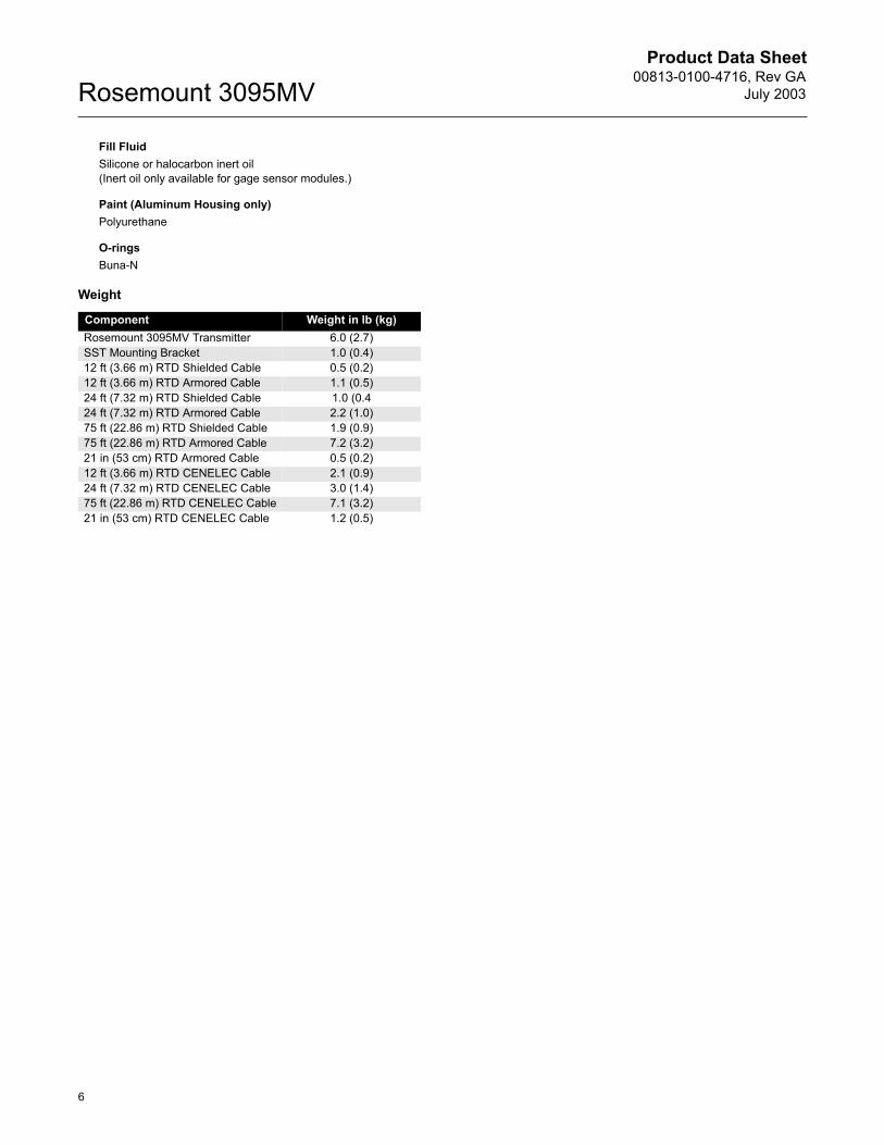
Weight
Component Weight in lb (kg)Rosemount 3095MV Transmitter 6.0 (2.7)SST Mounting Bracket 1.0 (0.4)12 ft (3.66 m) RTD Shielded Cable 0.5 (0.2)12 ft (3.66 m) RTD Armored Cable 1.1 (0.5)24 ft (7.32 m) RTD Shielded Cable 1.0 (0.424 ft (7.32 m) RTD Armored Cable 2.2 (1.0)75 ft (22.86 m) RTD Shielded Cable 1.9 (0.9)75 ft (22.86 m) RTD Armored Cable 7.2 (3.2)21 in (53 cm) RTD Armored Cable 0.5 (0.2)12 ft (3.66 m) RTD CENELEC Cable 2.1 (0.9)24 ft (7.32 m) RTD CENELEC Cable 3.0 (1.4)75 ft (22.86 m) RTD CENELEC Cable 7.1 (3.2)21 in (53 cm) RTD CENELEC Cable 1.2 (0.5)
Product Data Sheet00813-0100-4716, Rev GAJuly 2003
7
Rosemount 3095MV
Product Certifications
Approved Manufacturing LocationsRosemount Inc. Chanhassen, Minnesota USAFisher-Rosemount GmbH & Co. Wessling, GermanyEmerson Process Management Asia Pacific
Private Limited SingaporeBeijing Rosemount Far East Instrument Co., Limited Beijing, China
European Directive InformationThe EC declaration of conformity for all applicable European directives for this product can be found on the Rosemount website at www.rosemount.com. A hard copy may be obtained by contacting our local sales office.
ATEX Directive (94/9/EC)Emerson Process Management complies with the ATEX Directive.
European Pressure Equipment Directive (PED) (97/23/EC)
Models 3095F_2/3,4/D and 3095M_2/3,4/D Flow Transmitters QS Certificate of Assessment - EC No. PED-H-20Module H Conformity AssessmentAll other Model 3095_ Transmitters/Level Controller Sound Engineering PracticeTransmitter Attachments: Process Flange - Manifold Sound Engineering Practice
Electro Magnetic Compatibility (EMC) (89/336/EEC)
Model 3095MV Flow Transmitters EN 50081-1: 1992; EN 50082-2:1995; EN 61326-1:1997 Industrial
Ordinary Location Certification for Factory MutualAs standard, the transmitter has been examined and tested to determine that the design meets basic electrical, mechanical, and fire protection requirements by FM, a nationally recognized testing laboratory (NRTL) as accredited by the Federal Occupational Safety and Health Administration (OSHA).
Hazardous Locations Certifications
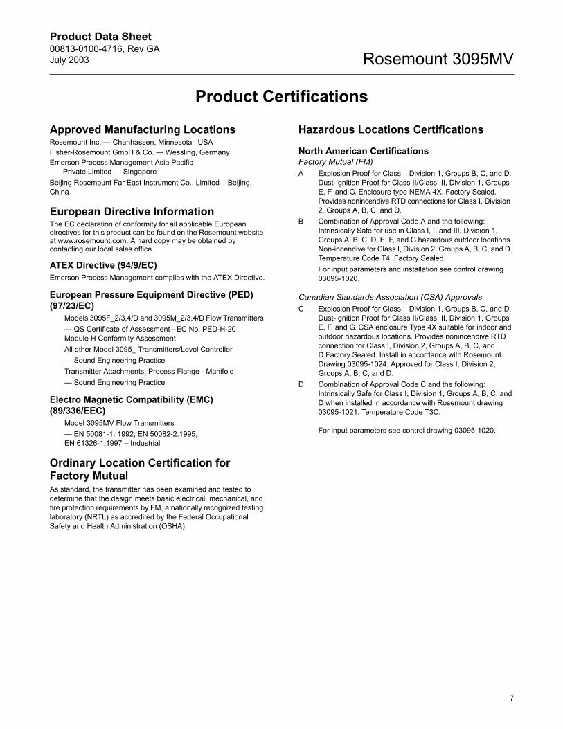
North American CertificationsFactory Mutual (FM)A Explosion Proof for Class I, Division 1, Groups B, C, and D.
Dust-Ignition Proof for Class II/Class III, Division 1, Groups E, F, and G. Enclosure type NEMA 4X. Factory Sealed. Provides nonincendive RTD connections for Class I, Division 2, Groups A, B, C, and D.
B Combination of Approval Code A and the following: Intrinsically Safe for use in Class I, II and III, Division 1, Groups A, B, C, D, E, F, and G hazardous outdoor locations. Non-incendive for Class I, Division 2, Groups A, B, C, and D. Temperature Code T4. Factory Sealed. For input parameters and installation see control drawing 03095-1020.
Canadian Standards Association (CSA) ApprovalsC Explosion Proof for Class I, Division 1, Groups B, C, and D.
Dust-Ignition Proof for Class II/Class III, Division 1, Groups E, F, and G. CSA enclosure Type 4X suitable for indoor and outdoor hazardous locations. Provides nonincendive RTD connection for Class I, Division 2, Groups A, B, C, and D.Factory Sealed. Install in accordance with Rosemount Drawing 03095-1024. Approved for Class I, Division 2, Groups A, B, C, and D.
D Combination of Approval Code C and the following: Intrinsically Safe for Class I, Division 1, Groups A, B, C, and D when installed in accordance with Rosemount drawing 03095-1021. Temperature Code T3C.
For input parameters see control drawing 03095-1020.
Product Data Sheet00813-0100-4716, Rev GA
July 2003Rosemount 3095MV
8
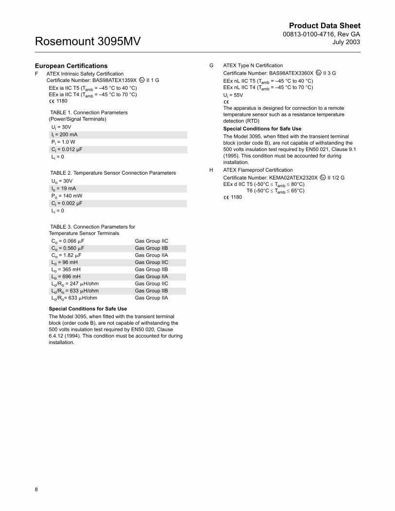
European CertificationsF ATEX Intrinsic Safety Certification
Certificate Number: BAS98ATEX1359X II 1 GEEx ia IIC T5 (Tamb = 45 °C to 40 °C)EEx ia IIC T4 (Tamb = 45 °C to 70 °C)
1180
Special Conditions for Safe Use The Model 3095, when fitted with the transient terminal block (order code B), are not capable of withstanding the 500 volts insulation test required by EN50 020, Clause 6.4.12 (1994). This condition must be accounted for during installation.
G ATEX Type N CertificationCertificate Number: BAS98ATEX3360X II 3 GEEx nL IIC T5 (Tamb = 45 °C to 40 °C)EEx nL IIC T4 (Tamb = 45 °C to 70 °C)Ui = 55V
The apparatus is designed for connection to a remote temperature sensor such as a resistance temperature detection (RTD)Special Conditions for Safe Use The Model 3095, when fitted with the transient terminal block (order code B), are not capable of withstanding the 500 volts insulation test required by EN50 021, Clause 9.1 (1995). This condition must be accounted for during installation.
H ATEX Flameproof CertificationCertificate Number: KEMA02ATEX2320X II 1/2 GEEx d IIC T5 (-50°C ≤ Tamb ≤ 80°C)
T6 (-50°C ≤ Tamb ≤ 65°C) 1180
TABLE 1. Connection Parameters (Power/Signal Terminals)Ui = 30VIi = 200 mAPi = 1.0 W Ci = 0.012 µFLi = 0
TABLE 2. Temperature Sensor Connection ParametersUo = 30VIo = 19 mAPo = 140 mW Ci = 0.002 µFLi = 0
TABLE 3. Connection Parameters for Temperature Sensor TerminalsCo = 0.066 F Gas Group IICCo = 0.560 F Gas Group IIBCo = 1.82 F Gas Group IIALo = 96 mH Gas Group IICLo = 365 mH Gas Group IIBLo = 696 mH Gas Group IIALo/Ro = 247 H/ohm Gas Group IICLo/Ro = 633 H/ohm Gas Group IIBLo/Ro= 633 H/ohm Gas Group IIA
Product Data Sheet00813-0100-4716, Rev GAJuly 2003
9
Rosemount 3095MV
Dimensional Drawings
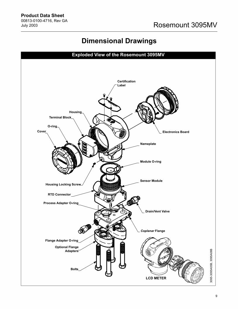
Exploded View of the Rosemount 3095MV
Sensor Module
Drain/Vent Valve
Coplanar Flange
Bolts
Optional FlangeAdapters
Flange Adapter O-ring
Certification Label
Electronics Board
Nameplate
Module O-ring
Process Adapter O-ring
RTD Connector
Housing Locking Screw
CoverO-ring
Terminal BlockHousing
LCD METER
3095
-309
5A05
B, 3
095A
08B
Product Data Sheet00813-0100-4716, Rev GA
July 2003Rosemount 3095MV
10
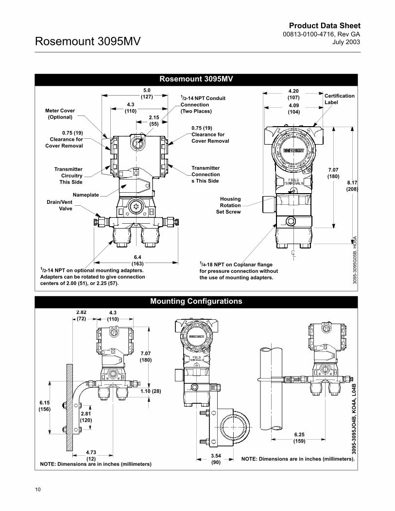
Rosemount 3095MV
Mounting Configurations
Meter Cover (Optional)
5.0 (127)
4.3 (110)
2.15 (55)
6.4 (163)
0.75 (19)Clearance for
Cover Removal
TransmitterCircuitry
This Side
NameplateDrain/Vent
Valve
1/2-14 NPT on optional mounting adapters. Adapters can be rotated to give connection centers of 2.00 (51), or 2.25 (57).
1/2-14 NPT Conduit Connection(Two Places)
0.75 (19)Clearance for Cover Removal
Transmitter Connections This Side
4.20 (107)4.09 (104)
7.07 (180)
8.17 (208)
Certification Label
HousingRotation
Set Screw
1/4-18 NPT on Coplanar flange for pressure connection without the use of mounting adapters.
3095
-309
5G05
B, H
O5A
3.54 (90) NOTE: Dimensions are in inches (millimeters).
6.25 (159)
3095
-309
5JO
4B, K
O4A
, L04
B
1.10 (28)
4.73 (12)
7.07 (180)
4.3 (110)
2.82 (72)
2.81 (120)
6.15 (156)
NOTE: Dimensions are in inches (millimeters)
Product Data Sheet00813-0100-4716, Rev GAJuly 2003
11
Rosemount 3095MV
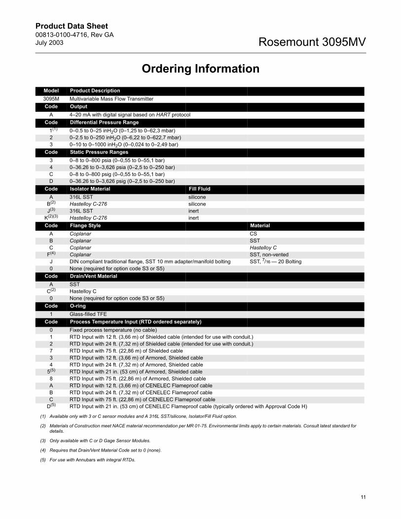
Ordering InformationModel Product Description3095M Multivariable Mass Flow TransmitterCode Output
A 420 mA with digital signal based on HART protocol Code Differential Pressure Range
1(1)
(1) Available only with 3 or C sensor modules and A 316L SST/silicone, Isolator/Fill Fluid option.
00.5 to 025 inH2O (01,25 to 062,3 mbar)2 02.5 to 0250 inH2O (06,22 to 0622,7 mbar)3 010 to 01000 inH2O (00,024 to 02,49 bar)
Code Static Pressure Ranges3 08 to 0800 psia (00,55 to 055,1 bar)4 036.26 to 03,626 psia (02,5 to 0250 bar)C 08 to 0800 psig (00,55 to 055,1 bar) D 036.26 to 03,626 psig (02,5 to 0250 bar)
Code Isolator Material Fill FluidA 316L SST silicone
B(2)
(2) Materials of Construction meet NACE material recommendation per MR 01-75. Environmental limits apply to certain materials. Consult latest standard for details.
Hastelloy C-276 siliconeJ(3)
(3) Only available with C or D Gage Sensor Modules.
316L SST inert K(2)(3) Hastelloy C-276 inert Code Flange Style Material
A Coplanar CSB Coplanar SSTC Coplanar Hastelloy C
F(4)
(4) Requires that Drain/Vent Material Code set to 0 (none).
Coplanar SST, non-ventedJ DIN compliant traditional flange, SST 10 mm adapter/manifold bolting SST, 7/16 20 Bolting0 None (required for option code S3 or S5)
Code Drain/Vent MaterialA SST
C(2) Hastelloy C0 None (required for option code S3 or S5)
Code O-ring1 Glass-filled TFE
Code Process Temperature Input (RTD ordered separately)0 Fixed process temperature (no cable) 1 RTD Input with 12 ft. (3,66 m) of Shielded cable (intended for use with conduit.)2 RTD Input with 24 ft. (7,32 m) of Shielded cable (intended for use with conduit.)7 RTD Input with 75 ft. (22,86 m) of Shielded cable3 RTD Input with 12 ft. (3,66 m) of Armored, Shielded cable4 RTD Input with 24 ft. (7,32 m) of Armored, Shielded cable
5(5)
(5) For use with Annubars with integral RTDs.
RTD Input with 21 in. (53 cm) of Armored, Shielded cable8 RTD Input with 75 ft. (22,86 m) of Armored, Shielded cableA RTD Input with 12 ft. (3,66 m) of CENELEC Flameproof cableB RTD Input with 24 ft. (7,32 m) of CENELEC Flameproof cableC RTD Input with 75 ft. (22,86 m) of CENELEC Flameproof cable
D(5) RTD Input with 21 in. (53 cm) of CENELEC Flameproof cable (typically ordered with Approval Code H)
Product Data Sheet00813-0100-4716, Rev GA
July 2003Rosemount 3095MV
12
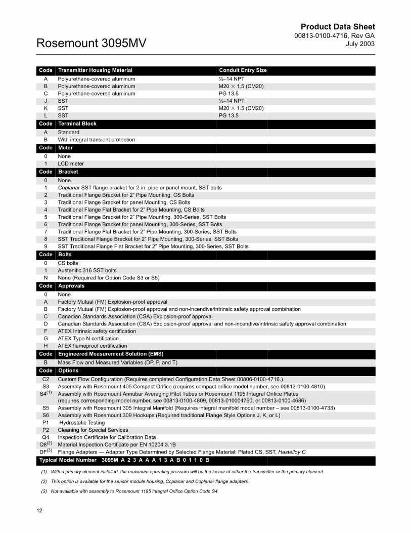
Code Transmitter Housing Material Conduit Entry SizeA Polyurethane-covered aluminum ½14 NPTB Polyurethane-covered aluminum M20 1.5 (CM20)C Polyurethane-covered aluminum PG 13.5J SST ½14 NPTK SST M20 1.5 (CM20)L SST PG 13.5
Code Terminal BlockA StandardB With integral transient protection
Code Meter0 None1 LCD meter
Code Bracket0 None1 Coplanar SST flange bracket for 2-in. pipe or panel mount, SST bolts2 Traditional Flange Bracket for 2 Pipe Mounting, CS Bolts3 Traditional Flange Bracket for panel Mounting, CS Bolts4 Traditional Flange Flat Bracket for 2 Pipe Mounting, CS Bolts5 Traditional Flange Bracket for 2 Pipe Mounting, 300-Series, SST Bolts6 Traditional Flange Bracket for panel Mounting, 300-Series, SST Bolts7 Traditional Flange Flat Bracket for 2 Pipe Mounting, 300-Series, SST Bolts8 SST Traditional Flange Bracket for 2 Pipe Mounting, 300-Series, SST Bolts9 SST Traditional Flange Flat Bracket for 2 Pipe Mounting, 300-Series, SST Bolts
Code Bolts 0 CS bolts1 Austenitic 316 SST boltsN None (Required for Option Code S3 or S5)
Code Approvals 0 None A Factory Mutual (FM) Explosion-proof approvalB Factory Mutual (FM) Explosion-proof approval and non-incendive/intrinsic safety approval combinationC Canadian Standards Association (CSA) Explosion-proof approvalD Canadian Standards Association (CSA) Explosion-proof approval and non-incendive/intrinsic safety approval combinationF ATEX Intrinsic safety certificationG ATEX Type N certificationH ATEX flameproof certification
Code Engineered Measurement Solution (EMS) B Mass Flow and Measured Variables (DP, P, and T)
Code OptionsC2 Custom Flow Configuration (Requires completed Configuration Data Sheet 00806-0100-4716.) S3 Assembly with Rosemount 405 Compact Orifice (requires compact orifice model number, see 00813-0100-4810)
S4(1) Assembly with Rosemount Annubar Averaging Pitot Tubes or Rosemount 1195 Integral Orifice Plates(requires corresponding model number, see 00813-0100-4809, 00813-010004760, or 00813-0100-4686)
S5 Assembly with Rosemount 305 Integral Manifold (Requires integral manifold model number see 00813-0100-4733)S6 Assembly with Rosemount 309 Hookups (Required traditional Flange Style Options J, K, or L)P1 Hydrostatic TestingP2 Cleaning for Special ServicesQ4 Inspection Certificate for Calibration Data
Q8(2) Material Inspection Certificate per EN 10204 3.1BDF(3) Flange Adapters Adapter Type Determined by Selected Flange Material: Plated CS, SST, Hastelloy C Typical Model Number 3095M A 2 3 A A A 1 3 A B 0 1 1 0 B
(1) With a primary element installed, the maximum operating pressure will be the lesser of either the transmitter or the primary element.
(2) This option is available for the sensor module housing, Coplanar and Coplanar flange adapters.
(3) Not available with assembly to Rosemount 1195 Integral Orifice Option Code S4.
Product Data Sheet00813-0100-4716, Rev GAJuly 2003
13
Rosemount 3095MV
OPTIONS
Standard Configuration Unless otherwise specified, transmitter is shipped as follows
In addition, transmitter is shipped as follows:
The three process variables are digitally trimmed to the specified upper and lower range values.
For Mass Flow and Measured Variables (EMS Code B), process variable output order is set to Flow, DP, AP/GP, PT.
Flow is configured to measure air via ASME Orifice: Flange Tap, with a primary element minimum diameter of 0.5 in. (SST material), meter tube diameter of 2 in. (carbon steel material), flow range configured from 08,262 SCFH, 10100 psia operating pressure range, and 50100 °F operating temperature range.
Custom Configuration (Option Code C2)
If Option Code C2 is ordered, the customer specifies the custom flow configuration parameters in addition to the standard configuration parameters.(See page 15)
Fixed Process Temperature
If process temperature input code is set to 0, the fixed process temperature is set to 68 °F unless specified during order entry.
Tagging
Three customer tagging options are available: Standard SST tag is wired to the transmitter.
Tag character height is 0.125 in. (3.18 mm),85 characters maximum.
Tag may be permanently stamped on transmitter nameplate upon request. Tag character height is 0.0625 in. (1.59 mm), 65 characters maximum.
Tag may be stored in transmitter memory. Software tag (8 characters maximum) is left blank unless specified.
Software tag (8 characters maximum) is left blank unless specified.
Assembly with Primary Elements (Option Code S3 or S4)
Rosemount 3095MV Flow Transmitters and either Annubar Averaging Pitot Tubes or Rosemount 1195 Integral Orifice Plates are fully assembled and calibrated by the factory.
Primary Element Product Data Sheets are listed below:
Optional Rosemount 305 Integral Manifolds
Rosemount 3095MV Transmitter and 305AC (305BC) Integral Manifold are fully assembled, calibrated, and seal tested by the factory. Refer to PDS 00813-0100-4733 for additional information.
Temperature Sensors and Assemblies
Rosemount offers many types of temperature sensors and assemblies.
Engineering units:Differential inH2O (Range 2) Absolute/gage psi (all ranges) Output: 4 - 20 mA HARTFlange type: Specified model code optionFlange material: Specified model code optionO-ring material: Specified model code optionDrain/vent: Specified model code optionFlow Configuration Parameters: Factory defaultSoftware tag: (Blank)
Annubar Flowmeter Series Includes: Rosemount 3051SFA ProbarRosemount 3095MFA Mass ProbarRosemount 485 Annubar Primary Element
00813-0100-4809
Proplate FlowmeterMass Proplate FlowmeterRosemount 1195 Integral Orifice Plate
00813-0100-4686
Rosemount 405P Compact Orifice 00813-0100-4810Rosemount 1495 Orifice PlateRosemount 1496 Flange UnionRosemount 1497 Meter Section
00813-0100-4792
Product Data Sheet00813-0100-4716, Rev GA
July 2003Rosemount 3095MV
14
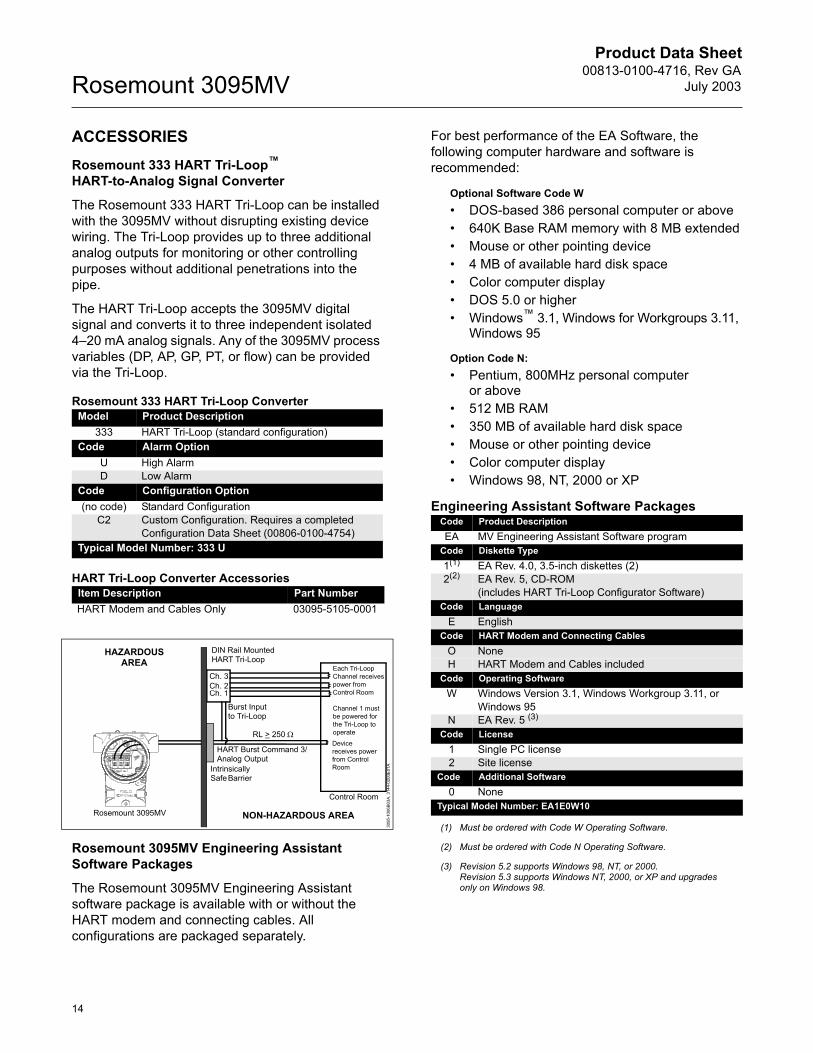
ACCESSORIESRosemount 333 HART Tri-Loop HART-to-Analog Signal Converter
The Rosemount 333 HART Tri-Loop can be installed with the 3095MV without disrupting existing device wiring. The Tri-Loop provides up to three additional analog outputs for monitoring or other controlling purposes without additional penetrations into the pipe.
The HART Tri-Loop accepts the 3095MV digital signal and converts it to three independent isolated 420 mA analog signals. Any of the 3095MV process variables (DP, AP, GP, PT, or flow) can be provided via the Tri-Loop.
Rosemount 333 HART Tri-Loop Converter
HART Tri-Loop Converter Accessories
Rosemount 3095MV Engineering Assistant Software Packages
The Rosemount 3095MV Engineering Assistant software package is available with or without the HART modem and connecting cables. All configurations are packaged separately.
For best performance of the EA Software, the following computer hardware and software is recommended:
Optional Software Code W DOS-based 386 personal computer or above 640K Base RAM memory with 8 MB extended Mouse or other pointing device 4 MB of available hard disk space Color computer display DOS 5.0 or higher Windows 3.1, Windows for Workgroups 3.11,
Windows 95
Option Code N: Pentium, 800MHz personal computer
or above 512 MB RAM 350 MB of available hard disk space Mouse or other pointing device Color computer display Windows 98, NT, 2000 or XP
Engineering Assistant Software Packages
Model Product Description333 HART Tri-Loop (standard configuration)
Code Alarm OptionU High AlarmD Low Alarm
Code Configuration Option(no code) Standard Configuration
C2 Custom Configuration. Requires a completed Configuration Data Sheet (00806-0100-4754)
Typical Model Number: 333 U
Item Description Part NumberHART Modem and Cables Only 03095-5105-0001
HAZARDOUS AREA
NON-HAZARDOUS AREA
Intrinsically Safe Barrier
Control Room
Burst Inputto Tri-Loop
Each Tri-Loop Channel receives power from Control Room
Channel 1 must be powered for the Tri-Loop to operate
HART Burst Command 3/ Analog Output
Ch. 3
Ch. 1
Device receives power from Control Room
Rosemount 3095MV
RL > 250 Ω
DIN Rail Mounted HART Tri-Loop
Ch. 2
3095
-100
6B03
A, 3
144-
0200
E01A
Code Product DescriptionEA MV Engineering Assistant Software program
Code Diskette Type1(1)
(1) Must be ordered with Code W Operating Software.
EA Rev. 4.0, 3.5-inch diskettes (2)2(2)
(2) Must be ordered with Code N Operating Software.
EA Rev. 5, CD-ROM (includes HART Tri-Loop Configurator Software)
Code LanguageE English
Code HART Modem and Connecting CablesO NoneH HART Modem and Cables included
Code Operating SoftwareW Windows Version 3.1, Windows Workgroup 3.11, or
Windows 95N EA Rev. 5 (3)
(3) Revision 5.2 supports Windows 98, NT, or 2000.Revision 5.3 supports Windows NT, 2000, or XP and upgrades only on Windows 98.
Code License1 Single PC license2 Site license
Code Additional Software0 None
Typical Model Number: EA1E0W10
Product Data Sheet00813-0100-4716, Rev GAJuly 2003
15
Rosemount 3095MV
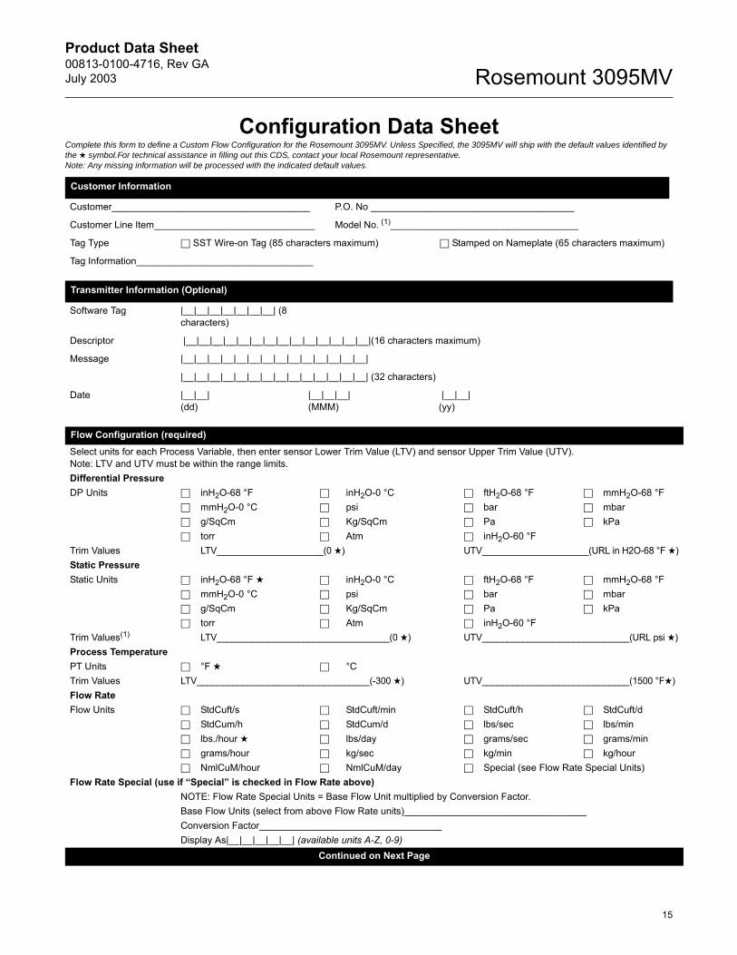
Configuration Data SheetComplete this form to define a Custom Flow Configuration for the Rosemount 3095MV. Unless Specified, the 3095MV will ship with the default values identified by the symbol.For technical assistance in filling out this CDS, contact your local Rosemount representative.Note: Any missing information will be processed with the indicated default values.
Customer Information
Customer_____________________________________ P.O. No ______________________________________
Customer Line Item______________________________ Model No. (1)___________________________________
Tag Type SST Wire-on Tag (85 characters maximum) Stamped on Nameplate (65 characters maximum)
Tag Information_________________________________
Transmitter Information (Optional)
Software Tag |__|__|__|__|__|__|__| (8 characters)
Descriptor |__|__|__|__|__|__|__|__|__|__|__|__|__|__|(16 characters maximum)
Message |__|__|__|__|__|__|__|__|__|__|__|__|__|__|
|__|__|__|__|__|__|__|__|__|__|__|__|__|__| (32 characters)
Date |__|__|(dd)
|__|__|__|(MMM)
|__|__|(yy)
Flow Configuration (required)Select units for each Process Variable, then enter sensor Lower Trim Value (LTV) and sensor Upper Trim Value (UTV).Note: LTV and UTV must be within the range limits.Differential PressureDP Units inH2O-68 °F inH2O-0 °C ftH2O-68 °F mmH2O-68 °F
mmH2O-0 °C psi bar mbar g/SqCm Kg/SqCm Pa kPa torr Atm inH2O-60 °F
Trim Values LTV_____________________(0 ) UTV_____________________(URL in H2O-68 °F )Static PressureStatic Units inH2O-68 °F inH2O-0 °C ftH2O-68 °F mmH2O-68 °F
mmH2O-0 °C psi bar mbar g/SqCm Kg/SqCm Pa kPa torr Atm inH2O-60 °F
Trim Values(1) LTV__________________________________(0 ) UTV_____________________________(URL psi )Process TemperaturePT Units °F °CTrim Values LTV__________________________________(-300 ) UTV_____________________________(1500 °F)Flow RateFlow Units StdCuft/s StdCuft/min StdCuft/h StdCuft/d
StdCum/h StdCum/d lbs/sec lbs/min lbs./hour lbs/day grams/sec grams/min grams/hour kg/sec kg/min kg/hour NmlCuM/hour NmlCuM/day Special (see Flow Rate Special Units)
Flow Rate Special (use if Special is checked in Flow Rate above)NOTE: Flow Rate Special Units = Base Flow Unit multiplied by Conversion Factor.Base Flow Units (select from above Flow Rate units)__________________________________Conversion Factor__________________________________Display As|__|__|__|__|__| (available units A-Z, 0-9)
Continued on Next Page
Product Data Sheet00813-0100-4716, Rev GA
July 2003Rosemount 3095MV
16
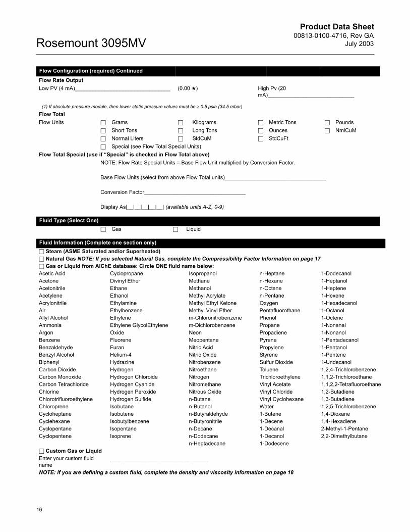
Flow Configuration (required) ContinuedFlow Rate OutputLow PV (4 mA)________________________________ (0.00 ) High Pv (20
mA)_____________________________
(1) If absolute pressure module, then lower static pressure values must be ≥ 0.5 psia (34.5 mbar)Flow TotalFlow Units Grams Kilograms Metric Tons Pounds
Short Tons Long Tons Ounces NmlCuM Normal Liters StdCuM StdCuFt Special (see Flow Total Special Units)
Flow Total Special (use if Special is checked in Flow Total above)NOTE: Flow Rate Special Units = Base Flow Unit multiplied by Conversion Factor.
Base Flow Units (select from above Flow Total units)__________________________________
Conversion Factor__________________________________
Display As|__|__|__|__|__| (available units A-Z, 0-9)
Fluid Type (Select One) Gas Liquid
Fluid Information (Complete one section only) Steam (ASME Saturated and/or Superheated) Natural Gas NOTE: If you selected Natural Gas, complete the Compressibility Factor Information on page 17 Gas or Liquid from AlChE database: Circle ONE fluid name below:Acetic Acid Cyclopropane Isopropanol n-Heptane 1-DodecanolAcetone Divinyl Ether Methane n-Hexane 1-HeptanolAcetonitrile Ethane Methanol n-Octane 1-HepteneAcetylene Ethanol Methyl Acrylate n-Pentane 1-HexeneAcrylonitrile Ethylamine Methyl Ethyl Ketone Oxygen 1-HexadecanolAir Ethylbenzene Methyl Vinyl Ether Pentafluorothane 1-OctanolAllyl Alcohol Ethylene m-Chloronitrobenzene Phenol 1-OcteneAmmonia Ethylene GlycolEthylene m-Dichlorobenzene Propane 1-NonanalArgon Oxide Neon Propadiene 1-NonanolBenzene Fluorene Meopentane Pyrene 1-PentadecanolBenzaldehyde Furan Nitric Acid Propylene 1-PentanolBenzyl Alcohol Helium-4 Nitric Oxide Styrene 1-PenteneBiphenyl Hydrazine Nitrobenzene Sulfur Dioxide 1-UndecanolCarbon Dioxide Hydrogen Nitroethane Toluene 1,2,4-TrichlorobenzeneCarbon Monoxide Hydrogen Chloroide Nitrogen Trichloroethylene 1,1,2-TrichloroethaneCarbon Tetrachloride Hydrogen Cyanide Nitromethane Vinyl Acetate 1,1,2,2-TetrafluoroethaneChlorine Hydrogen Peroxide Nitrous Oxide Vinyl Chloride 1,2-ButadieneChlorotrifluoroethylene Hydrogen Sulfide n-Butane Vinyl Cyclohexane 1,3-ButadieneChloroprene Isobutane n-Butanol Water 1,2,5-TrichlorobenzeneCycloheptane Isobutene n-Butyraldehyde 1-Butene 1,4-DioxaneCyclehexane Isobutylbenzene n-Butyronitrile 1-Decene 1,4-HexadieneCyclopentane Isopentane n-Decane 1-Decanal 2-Methyl-1-PentaneCyclopentene Isoprene n-Dodecane 1-Decanol 2,2-Dimethylbutane
n-Heptadecane 1-Dodecene Custom Gas or LiquidEnter your custom fluid name
_________________________________
NOTE: If you are defining a custom fluid, complete the density and viscosity information on page 18
Product Data Sheet00813-0100-4716, Rev GAJuly 2003
17
Rosemount 3095MV
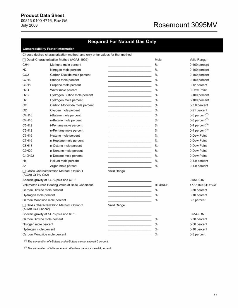
Required For Natural Gas OnlyCompressibility Factor Information
Choose desired characterization method, and only enter values for that method: Detail Characterization Method (AGA8 1992) Mole Valid RangeCH4 Methane mole percent _________________________ % 0-100 percentN2 Nitrogen mole percent _________________________ % 0-100 percentCO2 Carbon Dioxide mole percent _________________________ % 0-100 percentC2H6 Ethane mole percent _________________________ % 0-100 percentC3H8 Propane mole percent _________________________ % 0-12 percentH2O Water mole percent _________________________ % 0-Dew PointH2S Hydrogen Sulfide mole percent _________________________ % 0-100 percentH2 Hydrogen mole percent _________________________ % 0-100 percentCO Carbon Monoxide mole percent _________________________ % 0-3.0 percentO2 Oxygen mole percent _________________________ % 0-21 percentC4H10 i-Butane mole percent _________________________ % 0-6 percent(2)
C4H10 n-Butane mole percent _________________________ % 0-6 percent(2)
C5H12 i-Pentane mole percent _________________________ % 0-4 percent(3)
C5H12 n-Pentane mole percent _________________________ % 0-4 percent(3)
C6H16 Hexane mole percent _________________________ % 0-Dew PointC7H16 n-Heptane mole percent _________________________ % 0-Dew PointC8H18 n-Octane mole percent _________________________ % 0-Dew PointC9H20 n-Nonane mole percent _________________________ % 0-Dew PointC10H22 n-Decane mole percent _________________________ % 0-Dew PointHe Helium mole percent _________________________ % 0-3.0 percentAr Argon mole percent _________________________ % 0-1.0 percent Gross Characterization Method, Option 1 (AGA8 Gr-Hv-Co2)
Valid Range
Specific gravity at 14.73 psia and 60 °F _________________________ 0.554-0.87Volumetric Gross Heating Value at Base Conditions _________________________ BTU/SCF 477-1150 BTU/SCFCarbon Dioxide mole percent _________________________ % 0-30 percentHydrogen mole percent _________________________ % 0-10 percentCarbon Monoxide mole percent _________________________ % 0-3 percent Gross Characterization Method, Option 2 (AGA8 Gr-CO2-N2)
Valid Range
Specific gravity at 14.73 psia and 60 °F _________________________ 0.554-0.87Carbon Dioxide mole percent _________________________ % 0-30 percentNitrogen mole percent _________________________ % 0-50 percentHydrogen mole percent _________________________ % 0-10 percentCarbon Monoxide mole percent _________________________ % 0-3 percent
(2) The summation of i-Butane and n-Butane cannot exceed 6 percent.
(3) The summation of i-Pentane and n-Pentane cannot exceed 4 percent.
Product Data Sheet00813-0100-4716, Rev GA
July 2003Rosemount 3095MV
18
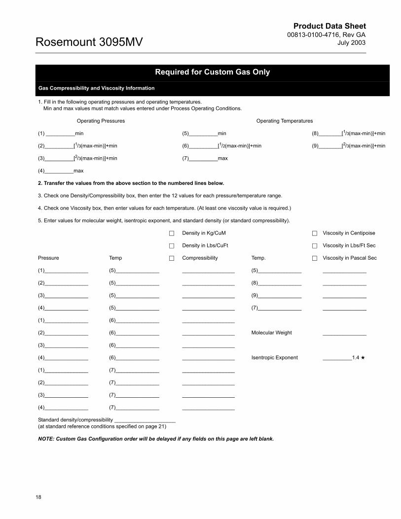
Required for Custom Gas Only
Gas Compressibility and Viscosity Information
1. Fill in the following operating pressures and operating temperatures.Min and max values must match values entered under Process Operating Conditions.
Operating Pressures Operating Temperatures
(1) __________min (5)__________min (8)________[1/3(max-min)]+min
(2)__________[1/3(max-min)]+min (6)__________[1/2(max-min)]+min (9)________[2/3(max-min)]+min
(3)__________[2/3(max-min)]+min (7)__________max
(4)__________max
2. Transfer the values from the above section to the numbered lines below.
3. Check one Density/Compressibility box, then enter the 12 values for each pressure/temperature range.
4. Check one Viscosity box, then enter values for each temperature. (At least one viscosity value is required.)
5. Enter values for molecular weight, isentropic exponent, and standard density (or standard compressibility).
Density in Kg/CuM Viscosity in Centipoise
Density in Lbs/CuFt Viscosity in Lbs/Ft Sec
Pressure Temp Compressibility Temp. Viscosity in Pascal Sec
(1)_______________ (5)_______________ __________________ (5)_______________ _______________
(2)_______________ (5)_______________ __________________ (8)_______________ _______________
(3)_______________ (5)_______________ __________________ (9)_______________ _______________
(4)_______________ (5)_______________ __________________ (7)_______________ _______________
(1)_______________ (6)_______________ __________________
(2)_______________ (6)_______________ __________________ Molecular Weight _______________
(3)_______________ (6)_______________ __________________
(4)_______________ (6)_______________ __________________ Isentropic Exponent __________1.4
(1)_______________ (7)_______________ __________________
(2)_______________ (7)_______________ __________________
(3)_______________ (7)_______________ __________________
(4)_______________ (7)_______________ __________________
Standard density/compressibility _____________________(at standard reference conditions specified on page 21)
NOTE: Custom Gas Configuration order will be delayed if any fields on this page are left blank.
Product Data Sheet00813-0100-4716, Rev GAJuly 2003
19
Rosemount 3095MV
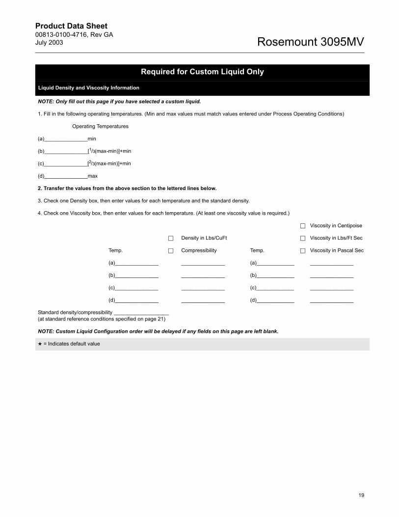
Required for Custom Liquid Only
Liquid Density and Viscosity Information
NOTE: Only fill out this page if you have selected a custom liquid.
1. Fill in the following operating temperatures. (Min and max values must match values entered under Process Operating Conditions)
Operating Temperatures
(a)_______________min
(b)_______________[1/3(max-min)]+min
(c)_______________[2/3(max-min)]+min
(d)_______________max
2. Transfer the values from the above section to the lettered lines below.
3. Check one Density box, then enter values for each temperature and the standard density.
4. Check one Viscosity box, then enter values for each temperature. (At least one viscosity value is required.)
Viscosity in Centipoise
Density in Lbs/CuFt Viscosity in Lbs/Ft Sec
Temp. Compressibility Temp. Viscosity in Pascal Sec
(a)_______________ _______________ (a)_____________ _______________
(b)_______________ _______________ (b)_____________ _______________
(c)_______________ _______________ (c)_____________ _______________
(d)_______________ _______________ (d)_____________ _______________
Standard density/compressibility ___________________(at standard reference conditions specified on page 21)
NOTE: Custom Liquid Configuration order will be delayed if any fields on this page are left blank.
= Indicates default value
Product Data Sheet00813-0100-4716, Rev GA
July 2003Rosemount 3095MV
20
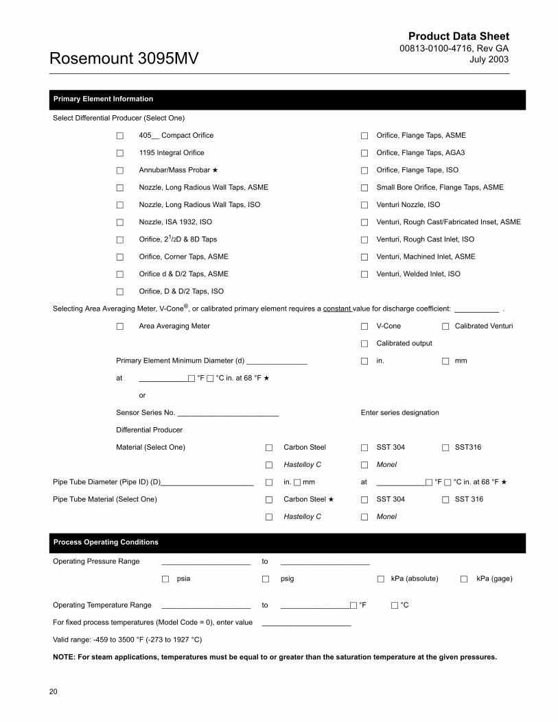
Primary Element Information
Select Differential Producer (Select One)
405__ Compact Orifice Orifice, Flange Taps, ASME
1195 Integral Orifice Orifice, Flange Taps, AGA3
Annubar/Mass Probar Orifice, Flange Tape, ISO
Nozzle, Long Radious Wall Taps, ASME Small Bore Orifice, Flange Taps, ASME
Nozzle, Long Radious Wall Taps, ISO Venturi Nozzle, ISO
Nozzle, ISA 1932, ISO Venturi, Rough Cast/Fabricated Inset, ASME
Orifice, 21/2D & 8D Taps Venturi, Rough Cast Inlet, ISO
Orifice, Corner Taps, ASME Venturi, Machined Inlet, ASME
Orifice d & D/2 Taps, ASME Venturi, Welded Inlet, ISO
Orifice, D & D/2 Taps, ISO
Selecting Area Averaging Meter, V-Cone®, or calibrated primary element requires a constant value for discharge coefficient: ___________ .
Area Averaging Meter V-Cone Calibrated Venturi
Calibrated output
Primary Element Minimum Diameter (d) _______________ in. mm
at ____________ °F °C in. at 68 °F
or
Sensor Series No. _________________________ Enter series designation
Differential Producer
Material (Select One) Carbon Steel SST 304 SST316
Hastelloy C Monel
Pipe Tube Diameter (Pipe ID) (D)_______________________ in. mm at ____________ °F °C in. at 68 °F
Pipe Tube Material (Select One) Carbon Steel SST 304 SST 316
Hastelloy C Monel
Process Operating Conditions
Operating Pressure Range ______________________ to ______________________
psia psig kPa (absolute) kPa (gage)
Operating Temperature Range ______________________ to _________________ °F °C
For fixed process temperatures (Model Code = 0), enter value ______________________
Valid range: -459 to 3500 °F (-273 to 1927 °C)
NOTE: For steam applications, temperatures must be equal to or greater than the saturation temperature at the given pressures.
Product Data Sheet00813-0100-4716, Rev GAJuly 2003
21
Rosemount 3095MV
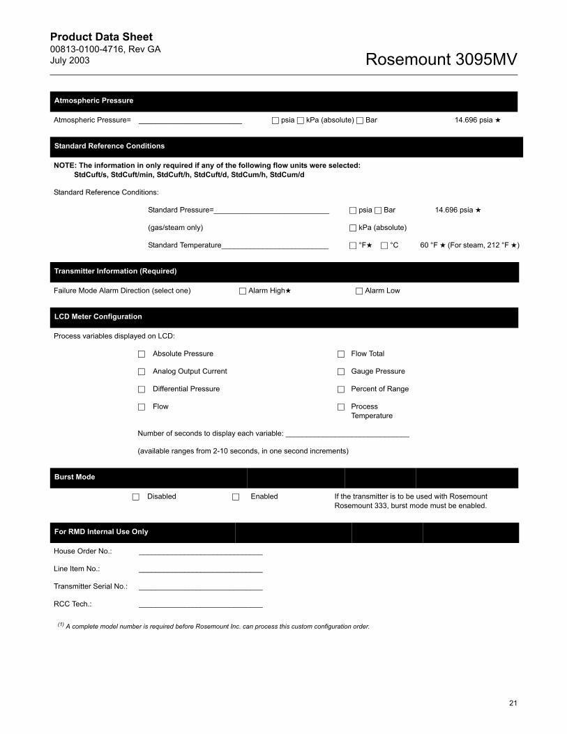
Atmospheric Pressure
Atmospheric Pressure= _________________________ psia kPa (absolute) Bar 14.696 psia
Standard Reference Conditions
NOTE: The information in only required if any of the following flow units were selected: StdCuft/s, StdCuft/min, StdCuft/h, StdCuft/d, StdCum/h, StdCum/d
Standard Reference Conditions:
Standard Pressure=____________________________ psia Bar 14.696 psia
(gas/steam only) kPa (absolute)
Standard Temperature__________________________ °F °C 60 °F (For steam, 212 °F )
Transmitter Information (Required)
Failure Mode Alarm Direction (select one) Alarm High Alarm Low
LCD Meter Configuration
Process variables displayed on LCD:
Absolute Pressure Flow Total
Analog Output Current Gauge Pressure
Differential Pressure Percent of Range
Flow Process Temperature
Number of seconds to display each variable: ______________________________
(available ranges from 2-10 seconds, in one second increments)
Burst Mode
Disabled Enabled If the transmitter is to be used with Rosemount Rosemount 333, burst mode must be enabled.
For RMD Internal Use Only
House Order No.: ______________________________
Line Item No.: ______________________________
Transmitter Serial No.: ______________________________
RCC Tech.: ______________________________
(1) A complete model number is required before Rosemount Inc. can process this custom configuration order.
Product Data Sheet00813-0100-4716, Rev GAJuly 2003 Rosemount 3095MV
Emerson Process Management
© 2003 Rosemount Inc. All rights reserved.
Fisher-Rosemount LimitedHeath Place Bognor RegisWest Sussex PO22 9SHEnglandTel 44 (1243) 863 121Fax 44 (1243) 867 5541
Rosemount and the Rosemount logotype are registerd trademarks of Rosemount Inc.Coplanar, MV, and Multivariable are trademarks of Rosemount Inc.PlantWeb is a mark of the Fisher-Rosemount group of companies.HART is a registered trademark of the HART Communication Foundation. Hastelloy C and Hastelloy C-276 are registered trademarks of Cabot Corp. Windows is a trademark of Microsoft Corp. Annubar is a registered trademark of Dieterich Standard Corporation V-Cone is a registered trademark of McCrometer.All other marks are the property of their respective owners.
Cover Photo: MV-3095001B, 3095-0619.
Approved by the Committee of Russian Federation for Standardization, Metrology and Certification (the Gosstandart of Russia) and registered in the Russian State Register of measuring instruments.
© 1995, 1996, 1998 Rosemount Inc. May be protected by one or more of the following U.S. Pat. Nos. 4,370,890; 4,612,812; 4,791,352; 4,798,089; 4,818,994; 4,833,922; 4,866,435; 4,926,340; 5,028,746. MEXICO PATENTADO NO. 154,961. Other U.S. and Foreign Patents Issued and Pending.
¢00813-0100-4716!¤
Rosemount Inc.8200 Market BoulevardChanhassen, MN 55317 USAT (U.S.) 1-800-999-9307T (International) (952) 906-8888F (952) 949-7001
www.rosemount.com
Fisher-Rosemount Singapore Pte Ltd.1 Pandan CrescentSingapore 128461Tel (65) 777-8211Fax (65) [email protected]


![[Ppt] Control Multivariable Predictivo](https://img.pdfslide.tips/doc/110x75/55cf856d550346484b8de241/ppt-control-multivariable-predictivo.jpg)