Embed Size (px)
Citation preview
File 146 Myra Place Phase 2, Kamloops, BC Page 1 of 2
Juniper West Developments Ltd. August 2, 2017 2049 Highland Place File: 146 Kamloops, BC V2E 0A8 Attention: Mr. Doug Mackenzie
Re: Geotechnical Summary Report – Juniper West Myra Place Phase 2 Myra Place, Kamloops, BC
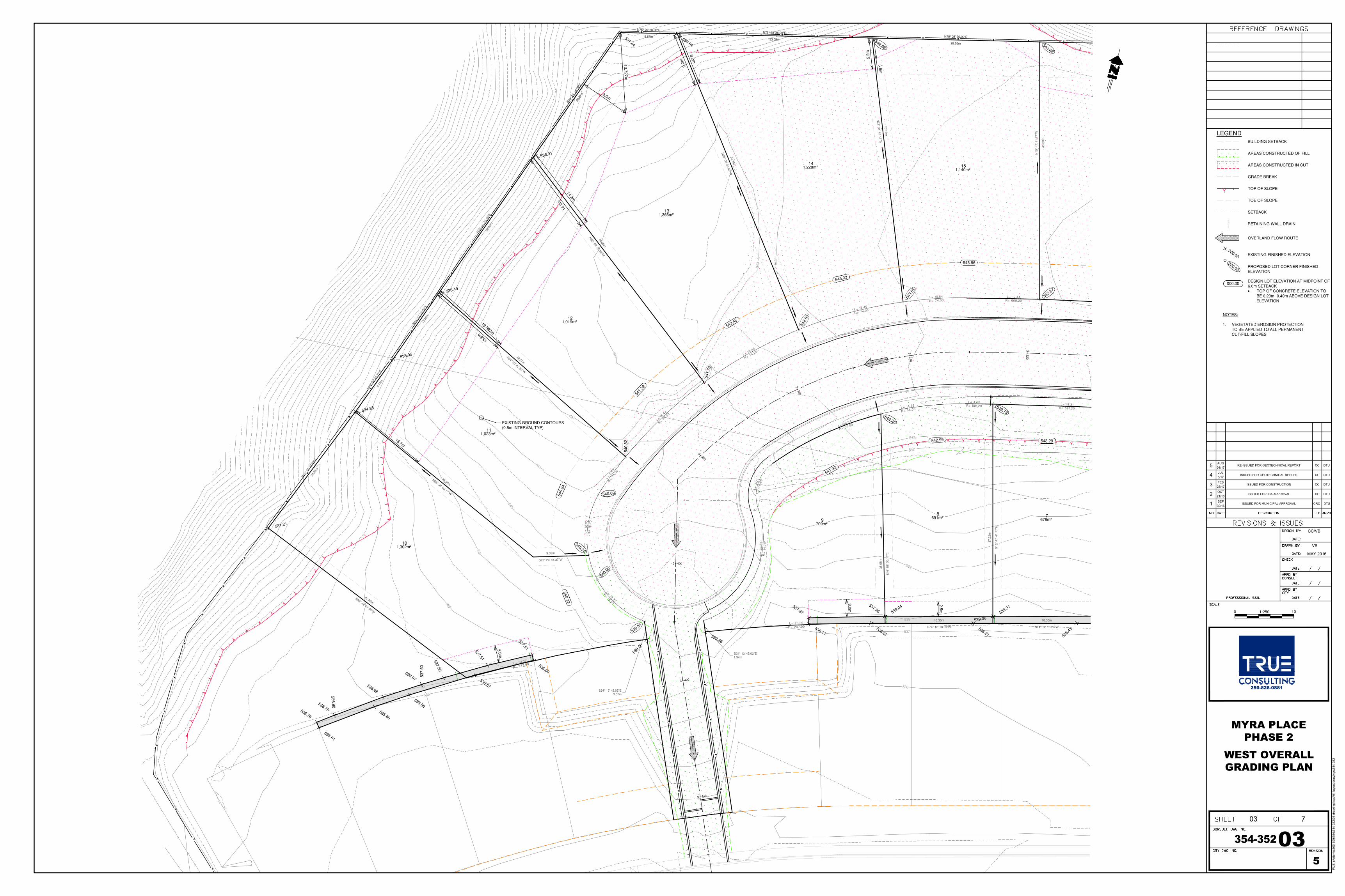
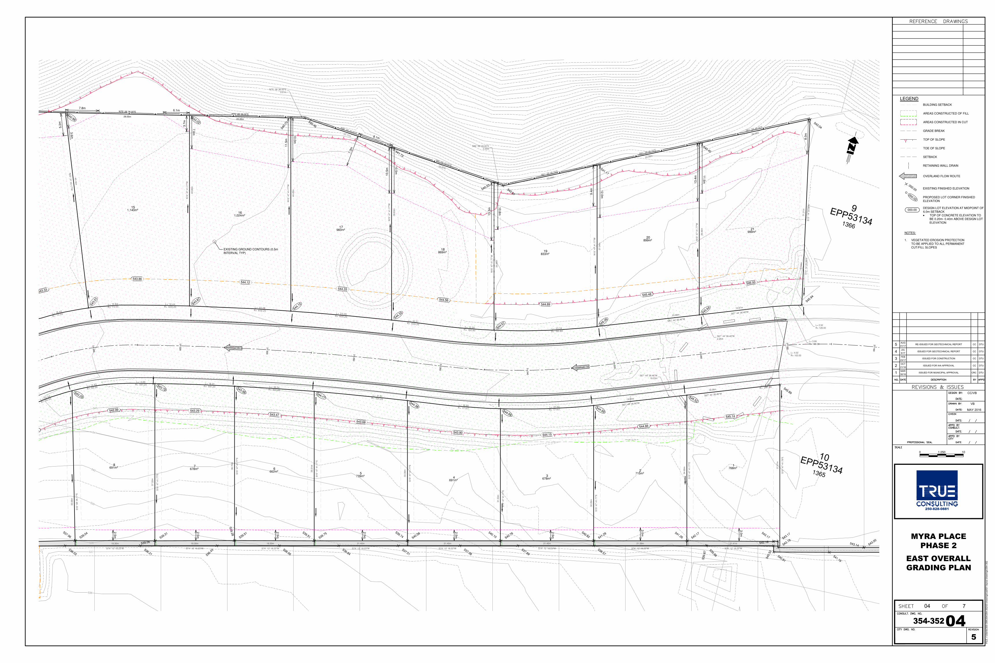
Telford Geotechnical Ltd. has conducted field reviews and materials testing during the earthworks, structural grading fills, utility installation and road construction. A reduced size set of the Comprehensive Site Grading Plan Drawings (354‐352‐03 Rev. 5, 354‐352‐04 Rev. 5 and 354‐352‐05 Rev. 5) are attached for reference. The subsurface soils encountered during the site works were generally consistent with our Geotechnical Report dated April 18, 2016. The stability of the lots 10 to 21 was analyzed using Bishop’s simplified limit equilibrium analysis which analyses the critical circular sliding surface. A minimum factor of safety of 1.5 is required for residential developments, therefore a top of slope setback has been recommended for each lot for the construction of permanent structures. It is recommended that the setback distance be surveyed in the field, or reviewed by the Geotechnical Engineer of Record (GER) prior to construction. Following our review of the site works, the following items have been included, or revised from the original report:
1. A building slope setback has been established for Lots 10 to 21 along the west and north slope in order to provide a safe building area for permanent structures that would include dwellings, decks attached to the dwelling, accessory buildings (excluding slab‐on‐grade structures <10m2 in size) and in‐ground swimming pools. Modifications to the slope setbacks may be possible by lowering the foundation, constructing retaining walls, or other methods designed by the GER.
2. A gabion wall was constructed along the rear yards of lots 1 to 10 and a setback zone of 1.5 x the wall height was established behind the retaining wall. Within the setback zone, no fill slopes may be constructed that exceed 2H:1V and no retaining walls, structures or pools can be constructed.
3. All grading fills in the subdivision were compacted to a minimum of 95% Modified Proctor (ASTM D1557) dry density.
4. The roof drains are to be connected to the municipal storm system. 5. The perimeter drains for lots 1 to 21 may drain by gravity to the rear yard where possible as there
is expected to be negligible groundwater on site, or they can be discharged into the municipal storm system.
6. The perimeter drains connected to the municipal storm system would require a backflow preventer in the event that the storm sewer surcharges.

File 146 Myra Place Phase 2, Kamloops, BC Page 2 of 2
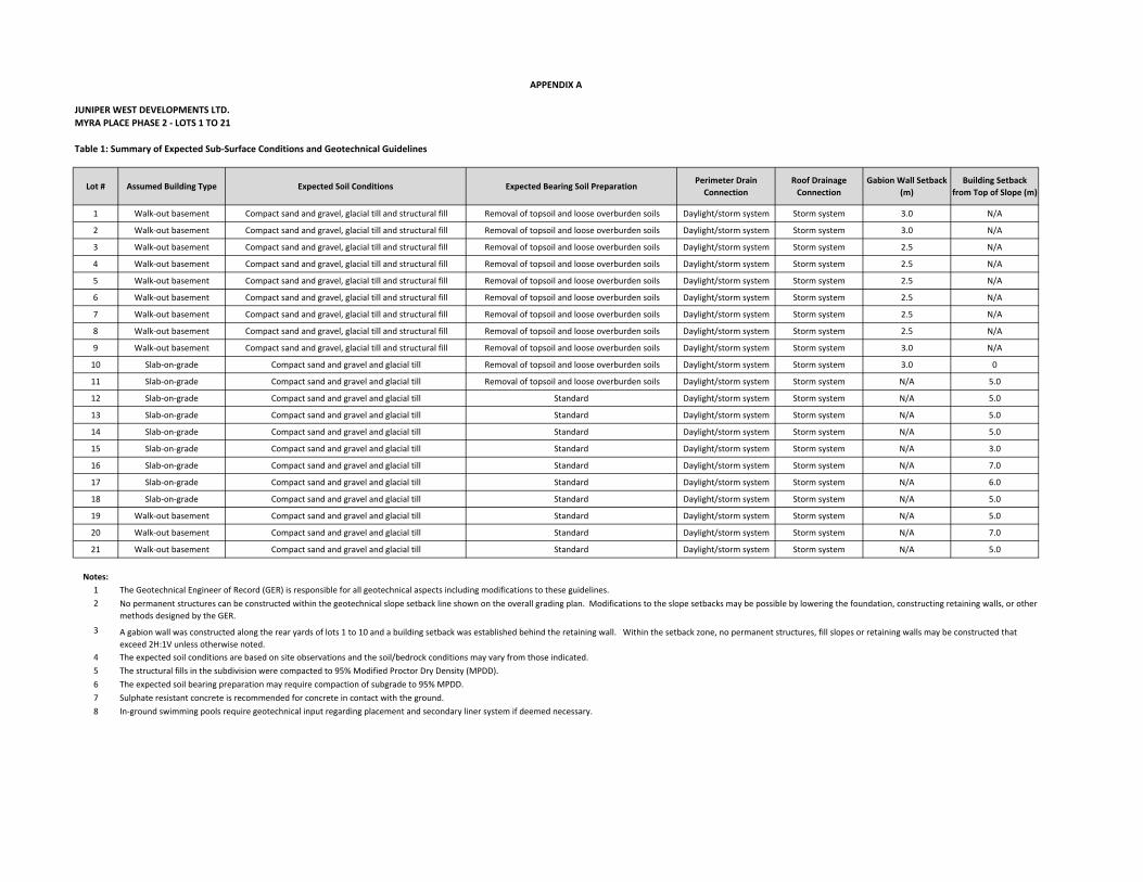
A summary table has been prepared “Summary of Expected Sub‐Surface Conditions and Geotechnical Guidelines” and is attached to this letter. If you would like further details or require clarification, please do not hesitate to contact the undersigned. For: Telford Geotechnical Ltd. Bill Telford, M.Eng., P.Eng. Geotechnical Engineer
JUNIPER WEST DEVELOPMENTS LTD.
MYRA PLACE PHASE 2 ‐ LOTS 1 TO 21
Table 1: Summary of Expected Sub‐Surface Conditions and Geotechnical Guidelines
Lot # Assumed Building Type Expected Soil Conditions Expected Bearing Soil PreparationPerimeter Drain
Connection
Roof Drainage
Connection
Gabion Wall Setback
(m)
Building Setback
from Top of Slope (m)
1 Walk‐out basement Compact sand and gravel, glacial till and structural fill Removal of topsoil and loose overburden soils Daylight/storm system Storm system 3.0 N/A
2 Walk‐out basement Compact sand and gravel, glacial till and structural fill Removal of topsoil and loose overburden soils Daylight/storm system Storm system 3.0 N/A
3 Walk‐out basement Compact sand and gravel, glacial till and structural fill Removal of topsoil and loose overburden soils Daylight/storm system Storm system 2.5 N/A
4 Walk‐out basement Compact sand and gravel, glacial till and structural fill Removal of topsoil and loose overburden soils Daylight/storm system Storm system 2.5 N/A
5 Walk‐out basement Compact sand and gravel, glacial till and structural fill Removal of topsoil and loose overburden soils Daylight/storm system Storm system 2.5 N/A
6 Walk‐out basement Compact sand and gravel, glacial till and structural fill Removal of topsoil and loose overburden soils Daylight/storm system Storm system 2.5 N/A
7 Walk‐out basement Compact sand and gravel, glacial till and structural fill Removal of topsoil and loose overburden soils Daylight/storm system Storm system 2.5 N/A
8 Walk‐out basement Compact sand and gravel, glacial till and structural fill Removal of topsoil and loose overburden soils Daylight/storm system Storm system 2.5 N/A
9 Walk‐out basement Compact sand and gravel, glacial till and structural fill Removal of topsoil and loose overburden soils Daylight/storm system Storm system 3.0 N/A
10 Slab‐on‐grade Compact sand and gravel and glacial till Removal of topsoil and loose overburden soils Daylight/storm system Storm system 3.0 0
11 Slab‐on‐grade Compact sand and gravel and glacial till Removal of topsoil and loose overburden soils Daylight/storm system Storm system N/A 5.0
12 Slab‐on‐grade Compact sand and gravel and glacial till Standard Daylight/storm system Storm system N/A 5.0
13 Slab‐on‐grade Compact sand and gravel and glacial till Standard Daylight/storm system Storm system N/A 5.0
14 Slab‐on‐grade Compact sand and gravel and glacial till Standard Daylight/storm system Storm system N/A 5.0
15 Slab‐on‐grade Compact sand and gravel and glacial till Standard Daylight/storm system Storm system N/A 3.0
16 Slab‐on‐grade Compact sand and gravel and glacial till Standard Daylight/storm system Storm system N/A 7.0
17 Slab‐on‐grade Compact sand and gravel and glacial till Standard Daylight/storm system Storm system N/A 6.0
18 Slab‐on‐grade Compact sand and gravel and glacial till Standard Daylight/storm system Storm system N/A 5.0
19 Walk‐out basement Compact sand and gravel and glacial till Standard Daylight/storm system Storm system N/A 5.0
20 Walk‐out basement Compact sand and gravel and glacial till Standard Daylight/storm system Storm system N/A 7.0
21 Walk‐out basement Compact sand and gravel and glacial till Standard Daylight/storm system Storm system N/A 5.0
Notes:
1 The Geotechnical Engineer of Record (GER) is responsible for all geotechnical aspects including modifications to these guidelines.
2
3
4 The expected soil conditions are based on site observations and the soil/bedrock conditions may vary from those indicated.
5 The structural fills in the subdivision were compacted to 95% Modified Proctor Dry Density (MPDD).
6 The expected soil bearing preparation may require compaction of subgrade to 95% MPDD.
7 Sulphate resistant concrete is recommended for concrete in contact with the ground.
8 In‐ground swimming pools require geotechnical input regarding placement and secondary liner system if deemed necessary.
APPENDIX A
No permanent structures can be constructed within the geotechnical slope setback line shown on the overall grading plan. Modifications to the slope setbacks may be possible by lowering the foundation, constructing retaining walls, or other
methods designed by the GER.
A gabion wall was constructed along the rear yards of lots 1 to 10 and a building setback was established behind the retaining wall. Within the setback zone, no permanent structures, fill slopes or retaining walls may be constructed that
exceed 2H:1V unless otherwise noted.
536
537
538
539
540
541
542
543
543 54
3
536
537
538
539
540
541
542
543
+3
320
+3
340
+3360
+3380
+3 400
+3 420
+3 440
N15
° 47
' 41.
77"W
43.8
0m
N22° 31' 43.17"W
45.16m
N75° 28' 36.00"E
28.55m
N38° 06' 29.46"W54.38m
N75° 28' 36.00"E
33.09m
N52° 59' 26.03"W
48.02m
N19
° 01'
25.
00"E
25.8
7m
N75° 28' 36.00"E
9.67m
N64° 23' 42.32"W
42.21m
N19
° 01'
25.
00"E
28.0
0m
S72° 20' 41.37"W
9.39m
N66° 38' 03.17"W
39.06m
N21° 0
4' 3
4.83
"E
24.6
6m
N19
° 34'
48.
77"E
9.70
m
N19
° 01'
25.
00"E
13.6
2m
N68° 42' 07.88"W
42.28m
N19
° 01'
25.
00"E
25.8
7m
N75° 28' 36.00"E
9.67mN75° 28' 36.00"E
33.09mN75° 28' 36.00"E
28.55m
L= 31.39
R= 247.00
S16
° 58
' 36.
17"E
35.6
8m
L= 26.36R= 247.00
S15
° 47
' 41.
77"E
37.3
2m
S74° 12' 18.23"W
18.30m
S74° 12' 18.23"W
18.30m
535.95
537.44
534.85
531.21
539.
06539.26
536.19
536.91
542.86
538.64 543.22
543.79543.25
539.51
540.30
540.
82
541.
78
542.
83
543.
51
543.87
12
11
10
1514
13
789
1,019m²
1,023m²
1,302m²
1,140m²1,228m²
1,366m²
678m²691m²709m²
L=15.37
R=15.20
L=12
.07
R=
15.2
0
L=6.
54R=
74.0
0
L=18
.44
R=74
.00
L= 18.44
R= 74.00
L= 18.40
R= 74.00
L= 10.84R= 74.00
L= 12.44R= 609.20
L= 18.31R= 591.20
L= 4.66R= 591.20L= 14.52
R= 56.00
L= 20.34
R= 56.00
L=8.
71R
=6.
69L=
23.5
3R
=14
.79
S24° 13' 45.02"E3.07m
S24° 13' 45.02"E1.94m
540.
08
540.69
541.92
543.29542.99
540.23
540.
84
541.
32
542.45
543.33
543.86
539.31539.04537.97
536.11536.02
536.21 536.
43
537.51537.51537.50
537.
50
536.97536.98
536.98
536.75536.76
535.61
535.60
535.58
535.57
536.00
539.28
539.06
537.96
1
SEP
30/16
ISSUED FOR MUNICIPAL APPROVAL CRC DTU
EXISTING GROUND CONTOURS(0.5m INTERVAL TYP)
OVERLAND FLOW ROUTE
GRADE BREAK
BUILDING SETBACK
LEGEND
DESIGN LOT ELEVATION AT MIDPOINT OF6.0m SETBACK· TOP OF CONCRETE ELEVATION TO
BE 0.20m- 0.40m ABOVE DESIGN LOTELEVATION
EXISTING FINISHED ELEVATION
AREAS CONSTRUCTED OF FILL
AREAS CONSTRUCTED IN CUT
000.00
TOP OF SLOPE
TOE OF SLOPE
FILE
: r:\clients\300-399\354\354-352\03 draw
ings\cad\01 layout draw
ings\354-352
250-828-0881
MYRA PLACE
PHASE 2
WEST OVERALL
GRADING PLAN
CC/VB
VB
MAY 2016
354-352
03
03 7
5
0 101:250
000.00
000.00
PROPOSED LOT CORNER FINISHEDELEVATION
NOTES:
1. VEGETATED EROSION PROTECTIONTO BE APPLIED TO ALL PERMANENTCUT/FILL SLOPES
2
OCT
21/16
ISSUED FOR IHA APPROVAL CC DTU
3
FEB
23/17
ISSUED FOR CONSTRUCTION CC DTU
4
JUL
5/17
ISSUED FOR GEOTECHNICAL REPORT CC DTU
SETBACK
RETAINING WALL DRAIN
3.0m
3.0m
2.5m
13.7m
13.592m
14.2m
8.6m
13.727m
9.2m
3.6m5
AUG
01/17
RE-ISSUED FOR GEOTECHNICAL REPORT CC DTU
13.6m14
.2m
9.2m
5.2m
E
P
P
5
3
1
3
4
9
1366
E
P
P
5
3
1
3
4
1
0
1365
536
537
538
539
540
541
542
543
+3
160
+3
180
+3
200
+3
220
+3
240
+3
260
+3
280
+3
300
+3
320
+3
340
S13
° 14
' 33.
58"E
11.5
3m
N15
° 47
' 41.
77"W
39.4
6m
N61° 59' 46.79"E
26.04m
S13
° 14
' 33.
58"E
31.2
1m
N15
° 47
' 41.
77"W
37.0
4m
N61° 59' 46.79"E
24.06m
N15
° 47
' 41.
77"W
33.9
5m
S74° 12' 18.23"W
21.41m
S86° 59' 33.00"E2.20m
N61° 59' 46.79"E
22.04m
N15
° 47
' 41.
77"W
39.6
3m
S86° 59' 33.00"E24.87m
N15
° 47
' 41.
77"W
44.4
5m
N75° 28' 36.00"E3.21m
S86° 59' 33.00"E21.11m
N15
° 47
' 41.
77"W
43.8
0m
N75° 28' 36.00"E
23.26m
N22° 31' 43.17"W
45.16m
N75° 28' 36.00"E
28.55m
N75° 28' 36.00"E
28.55mN75° 28' 36.00"E
23.26m
S16
° 58
' 36.
17"E
35.6
8m
S15
° 47
' 41.
77"E
37.3
2m
S74° 12' 18.23"W
18.30m
S15
° 47
' 41.
77"E
36.7
0m
S74° 12' 18.23"W
18.30m
S15
° 47
' 41.
77"E
35.5
1m
S74° 12' 18.23"W
18.30m
S15
° 47
' 41.
77"E
33.3
9m
S74° 12' 18.23"W
21.40m
S15
° 47
' 41.
77"E
31.5
3m
S74° 12' 18.23"W
21.40m
S15
° 47
' 41.
77"E
32.2
6m
S74° 12' 18.23"W
21.40m
S15
° 47
' 41.
77"E
34.6
6m
S74° 12' 18.23"W
21.39m
S15
° 47
' 41.
79"E
37.0
7m
540.91
540.46543.04
545.94
545.89
542.86
540.
70
543.22
541.73
540.53
541.17
540.40
545.52
544.99544.59
544.38
544.17
543.98
543.79543.25
543.
51
543.87
544.10
544.33
544.57 545.06
545.64
20
1918
17
1615
21
678 1
234
5
899m²
833m²869m²
983m²
1,024m²
1,140m²
999m²
662m²678m²691m² 768m²
715m²
678m²691m²739m²
L= 18.40
R= 74.00
L= 10.84R= 74.00
L= 12.44R= 609.20 L= 23.28
R= 609.20L= 23.28
R= 609.20L= 10.37
R= 609.20L= 13.30
R= 150.80L= 23.34R= 150.80
S67° 44' 38.46"W23.66m
S67° 44' 38.46"W2.26m
S67° 44' 38.46"W10.87m
L= 4.02R= 163.00
L= 3.99R= 129.00
L= 2.52R= 129.00
L= 3.46R= 267.06
S67° 44' 38.46"W18.08m
S67° 44' 38.46"W19.03m
S67° 44' 38.46"W19.03m
L= 21.42R= 171.67
L= 16.99R= 171.67
L= 21.51R= 591.20
L= 18.34R= 591.20
L= 18.31R= 591.20
L= 4.66R= 591.20L= 14.52
R= 56.00
L= 20.34
R= 56.00
541.92
545.14
544.66
544.15543.90
543.68
543.47543.29542.99
544.89
543.33
543.86544.12
544.33
544.56
545.48
546.00
543.14543.19543.17543.17542.17541.29
540.78540.08
539.75539.51
539.31539.04
536.02536.21 53
6.43 536.66
536.84537.01
537.38537.89
538.57
539.
87
540.
52
540.81541.19
543.00542.16
541.26
540.82540.10
539.74539.51
539.28
539.06
537.96
539.88
1
MAR
30/16
ISSUED FOR MUNICIPAL APPROVAL CRC DTU
EXISTING GROUND CONTOURS (0.5mINTERVAL TYP)
FILE
: r:\clients\300-399\354\354-352\03 draw
ings\cad\01 layout draw
ings\354-352
250-828-0881
MYRA PLACE
PHASE 2
EAST OVERALL
GRADING PLAN
CC/VB
VB
MAY 2016
354-352
04
04 7
5
0 101:250
2
OCT
21/16
ISSUED FOR IHA APPROVAL CC DTU
3
FEB
23/17
ISSUED FOR CONSTRUCTION CC DTU
4
JUL
5/17
ISSUED FOR GEOTECHNICAL REPORT CC DTU
OVERLAND FLOW ROUTE
GRADE BREAK
BUILDING SETBACK
LEGEND
DESIGN LOT ELEVATION AT MIDPOINT OF6.0m SETBACK· TOP OF CONCRETE ELEVATION TO
BE 0.20m- 0.40m ABOVE DESIGN LOTELEVATION
EXISTING FINISHED ELEVATION
AREAS CONSTRUCTED OF FILL
AREAS CONSTRUCTED IN CUT
000.00
TOP OF SLOPE
TOE OF SLOPE
000.00
000.00
PROPOSED LOT CORNER FINISHEDELEVATION
NOTES:
1. VEGETATED EROSION PROTECTIONTO BE APPLIED TO ALL PERMANENTCUT/FILL SLOPES
SETBACK
RETAINING WALL DRAIN
2.5m
2.5m
2.5m
2.5m
2.5m
2.5m
3.0m
3.0m
3.6m
7.6m
6.1m7.8m
11.5
m
10.0m
10.5m
13.3
m
10.8m
9.4m
12.0m
13.4
m
11.5m
8.0m
3.7m
8.1m
5
AUG
01/17
RE-ISSUED FOR GEOTECHNICAL REPORT CC DTU
10.5
m
7.3m
5.2m
TYPICAL LOT GRADING (LOTS 10-18)SCALE 1:250
T.O. CONCRETE EL.0.20 - 0.40
PROPERTYLINE
BACK OF CURB
ROAD GRADE VARIES
6.0m
±18.4- ±23.2
PR
OP
ER
TY
LIN
E
BUILDING SETBACK LINE
-0.1
2
3.25
m6.
0m
REAR PROPERTY LINE
TYPICAL LOT GRADING (LOTS 1-9)SCALE 1:250
T.O. CONCRETE EL.0.20 - 0.40
BACK OF CURB
ROAD GRADE VARIES
6.0m
±25.5 - ±18.3
PR
OP
ER
TY
LIN
E
0.00
BUILDING SETBACK LINE
0.60
2.85
m
REAR PROPERTY LINE
VA
RIE
S
TOP OF 2:1 CONSTRUCTION SLOPE
NOTES:
1. FRONT YARDS OF LOTS 1-9 TO BE DIRECTED AROUND HOUSE TO SIDE YARDS.1.1. A TRENCH DRAIN OR SUMP WILL BE REQUIRED FOR DRIVEWAY DRAINAGE AND IS TO BE
CONNECTED DIRECTLY INTO THE MUNICIPAL STORM SYSTEM.
2. FRONT YARDS OF LOTS 10-21 TO MAINTAIN POSITIVE DRAINAGE TO THE STREET.
3. SIDE YARDS OF LOTS 1-21 TO MAINTAIN POSITIVE DRAINAGE AWAY FROM BUILDING TO REAR LOTLINE.
4. REAR YARDS OF LOTS 1-21 TO MAINTAIN POSITIVE DRAINAGE AWAY FROM BUILDING TO REAR LOTLINE.
5. FOUNDATION DRAINS OF LOTS 1-9 AND 19-21 TO DAYLIGHT IN REAR YARD WHERE POSSIBLE ANDPUMP TO MUNICIPAL STORM SYSTEM WHERE NOT POSSIBLE.
6. FOUNDATION DRAINS OF LOTS 10-18 TO DAYLIGHT IN REAR YARD WHERE POSSIBLE AND CONNECTTO THE MUNICIPAL STORM SYSTEM VIA GRAVITY OR PUMP WHERE NOT POSSIBLE.
7. ROOF DRAINS OF LOTS 1-21 TO CONNECT DIRECTLY TO MUNICIPAL STORM BY GRAVITY.
8. ALL FOUNDATION DRAINS CONNECTED TO MUNICIPAL STORM SYSTEM REQUIRE A BACKFLOWPREVENTOR UPSTREAM OF ROOF DRAIN CONNECTION.
9. GRADING OF LOTS 1-9 AND 19-21 BASED ON 2.74m BASEMENT HEIGHT.
10. MINOR ADJUSTMENTS TO DESIGN ELEVATIONS TO BE APPROVED BY THE GEOTECHNICAL ENGINEEROF RECORD.
11. REAR YARD DRAINAGE OF LOTS 1-9 TO BE ROUTED THROUGH LANDSCAPING AND CANNOT BECONCENTRATED.
12. LOTS 1-10 - A SETBACK ZONE HAS BEEN ESTABLISHED BEHIND THE RETAINING WALL. SEEGEOTECHNICAL REPORT FOR BUILDING RESTRICTIONS WITHIN THE SETBACK AREA.
13. LOTS 10-21 - A BUILDING SETBACK HAS BEEN ESTABLISHED ALONG THE WEST AND NORTH SLOPE.SEE GEOTECHNICAL REPORT FOR BUILDING RESTRICTIONS WITHIN THE SETBACK AREA.
FILE
: r:\clients\300-399\354\354-352\03 draw
ings\cad\01 layout draw
ings\354-352
250-828-0881
MYRA PLACE
PHASE 2
TYPICAL LOT
GRADING DETAILS
CC/VB
VB
MAY 2016
354-352
05
05 7
5
0 101:250
TOE OF 2:1 CONSTRUCTION SLOPE
VA
RIE
SP
RO
PE
RT
Y L
INE
VARIE
S
0.00
⅊
T.O. BASEMENTFLOORCONCRETE SLAB
0.2-0.4m (T.O. CONCRETE)
TYPICAL LOT SECTION THROUGH LOTS 1-9SCALE 1:100
6.0m MIN
12 PROPOSED LOT GRADE
AT BUILD OUT
T.O. MAIN FLOOR
MYRA PLACE
ALL ROOF DRAINS TO CONNECT DIRECTLY TO STORM DRAIN BY GRAVITY
STRUCTURAL FILL
1.2m MIN BELOWEXTERIOR FINAL GRADE
STRUCTURAL FILL
2%
DESIGN LOT ELEVATION AT MIDPOINT OF 6.0m SETBACK.(SEE GRADING PLAN FOR LOT ELEVATIONS)
2% MINIMUM
10% AVERAGE
EXISTING GROUND
TYPICAL LOT GRADING (LOTS 19-21)SCALE 1:250
T.O. CONCRETE EL.0.20 - 0.40
PROPERTYLINE
BACK OF CURB
ROAD GRADE VARIES
6.0m
±23.6
PR
OP
ER
TY
LIN
E
BUILDING SETBACK LINE
-0.1
2
3.25
m6.
0m
REAR PROPERTY LINE
VA
RIE
S
0.00
TOP OF 1:1 CONSTRUCTION SLOPE
TOE OF 1:1 CONSTRUCTION SLOPE
2.5m
2%
⅊
T.O. BASEMENTFLOOR
CONCRETE SLAB
0.2-0.4m (T.O. CONCRETE)
TYPICAL LOT SECTION THROUGH LOTS 19-21SCALE 1:100
6.0m MIN
11LOT GRADE AT BUILD OUT
T.O. MAIN FLOOR
MYRA PLACE
ALL ROOF DRAINS TO DISCHARGE TO STORM DRAIN BY GRAVITY
STRUCTURAL FILL
2.5m1.2m MIN BELOW
EXTERIOR FINAL GRADESTRUCTURAL FILL
2% AVERAGE
DESIGN LOT ELEVATION AT MIDPOINT OF 6.0m SETBACK.(SEE GRADING PLAN FOR LOT ELEVATIONS)
EXISTING GROUND
2%
⅊
CONCRETE SLAB
0.2-0.4m (T.O. CONCRETE)
TYPICAL LOT SECTION THROUGH LOTS 10-18SCALE 1:100
6.0m MIN
LOT GRADE AT BUILD OUT
T.O. MAIN FLOOR
MYRA PLACE
ALL ROOF DRAINS TO DISCHARGE TO STORM DRAIN BY GRAVITY
2% AVERAGE
DESIGN LOT ELEVATION AT MIDPOINT OF 6.0m SETBACK.(SEE GRADING PLAN FOR LOT ELEVATIONS)
EXISTING GROUND
2% MINIMUM
1.2m MIN BELOWEXTERIOR FINAL GRADE
1.2m MIN BELOWEXTERIOR FINAL GRADE
SEE NOTE 11
1
SEP
30/16
ISSUED FOR MUNICIPAL APPROVAL CC DTU
2
OCT
21/16
ISSUED FOR IHA APPROVAL CC DTU
RETAINING WALL SETBACK LINE(SEE NOTE 12)
3
FEB
23/17
ISSUED FOR CONSTRUCTION CC DTU
RETAINING WALL
⅊
SEE NOTE 13
SEE NOTE 13
⅊
SETBACK ZONE(SEE NOTE 12)
SLOPE SETBACK ZONELENGTH VARIES(SEE NOTE 13)
⅊
4
JUL
5/17
ISSUED FOR GEOTECHNICAL REPORT CC DTU
SLOPE SETBACK LINE
(SEE NOTE 13)
SLOPE SETBACK LINE
(SEE NOTE 13)
SLOPE SETBACK ZONELENGTH VARIES(SEE NOTE 13)
LOT GRADE AT BUILD OUT
LOT GRADE AT BUILD OUT
2% MINIMUM
5
AUG
01/17
RE-ISSUED FOR GEOTECHNICAL REPORT CC DTU