Embed Size (px)
Citation preview
Tech
nický
Katalog
česk
y
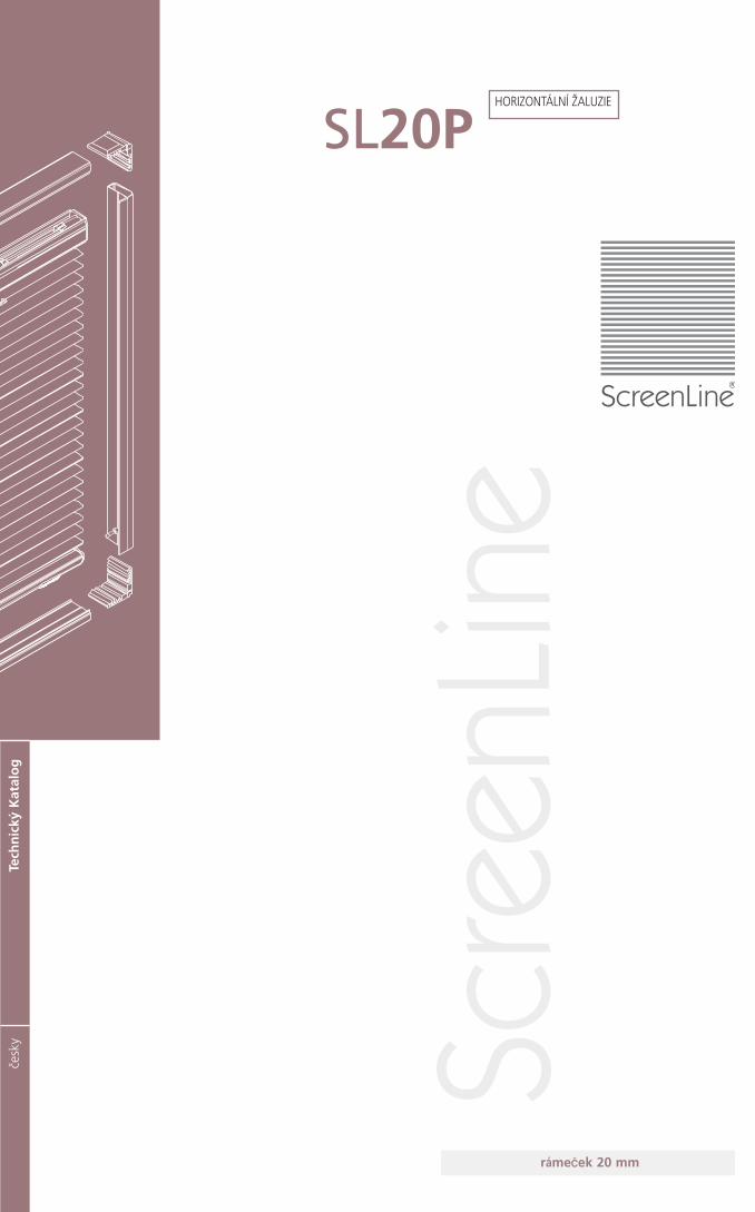
SL20P
rámezek 20 mm
Scre
enLin
e
HORIZONTÁLNÍ ŽALUZIE
SL20P
ScreenLine
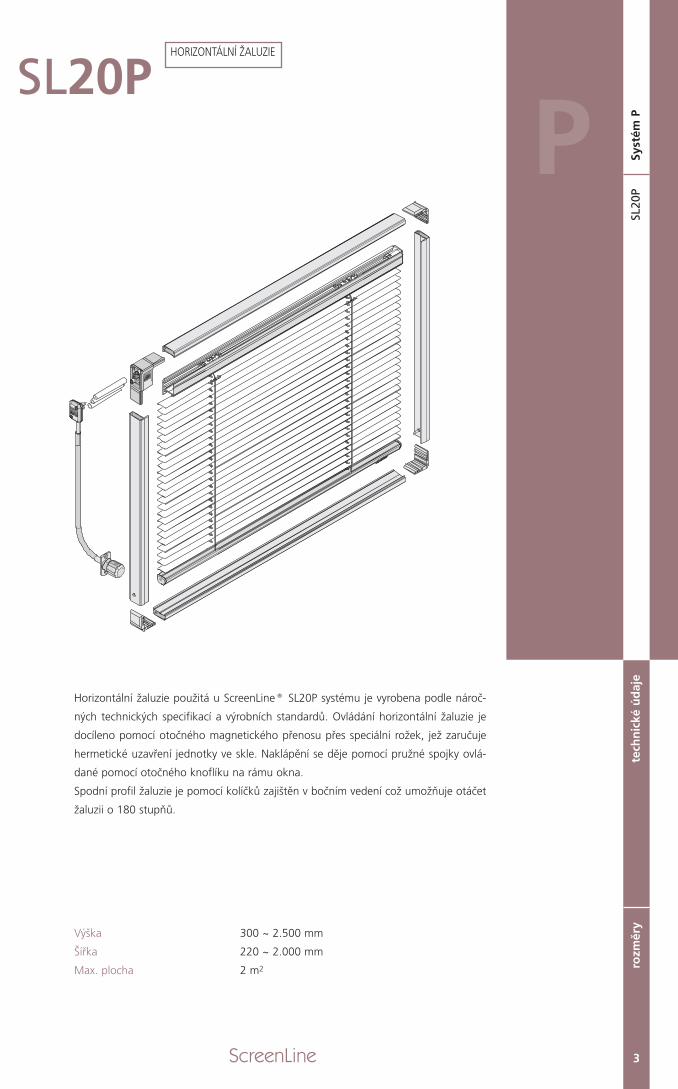
Horizontální žaluzie použitá u ScreenLine® SL20P systému je vyrobena podle nároč-
ných technických specifikací a výrobních standardů. Ovládání horizontální žaluzie je
docíleno pomocí otočného magnetického přenosu přes speciální rožek, jež zaručuje
hermetické uzavření jednotky ve skle. Naklápění se děje pomocí pružné spojky ovlá-
dané pomocí otočného knoflíku na rámu okna.
Spodní profil žaluzie je pomocí kolíčků zajištěn v bočním vedení což umožňuje otáčet
žaluzii o 180 stupňů.
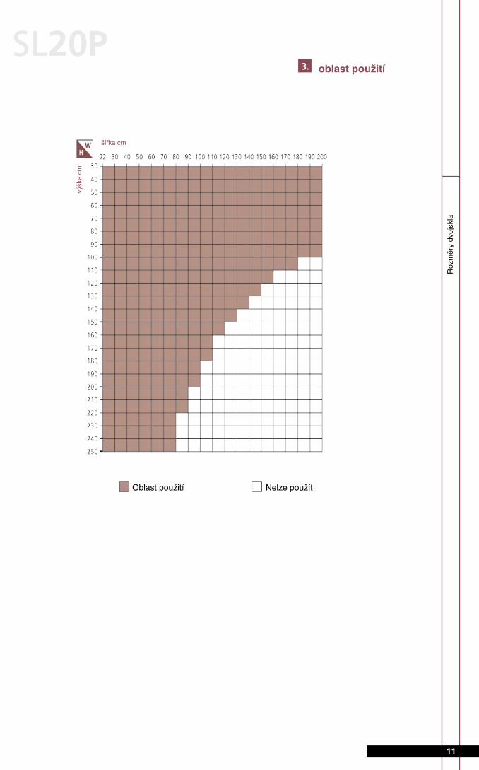
Výška 300 ~ 2.500 mm
Šířka 220 ~ 2.000 mm
Max. plocha 2 m2
3
tech
nic
ké ú
daj
ero
změr
ySL
20P
Syst
ém PP
HORIZONTÁLNÍ ŽALUZIE
ScreenLine4
SL20P
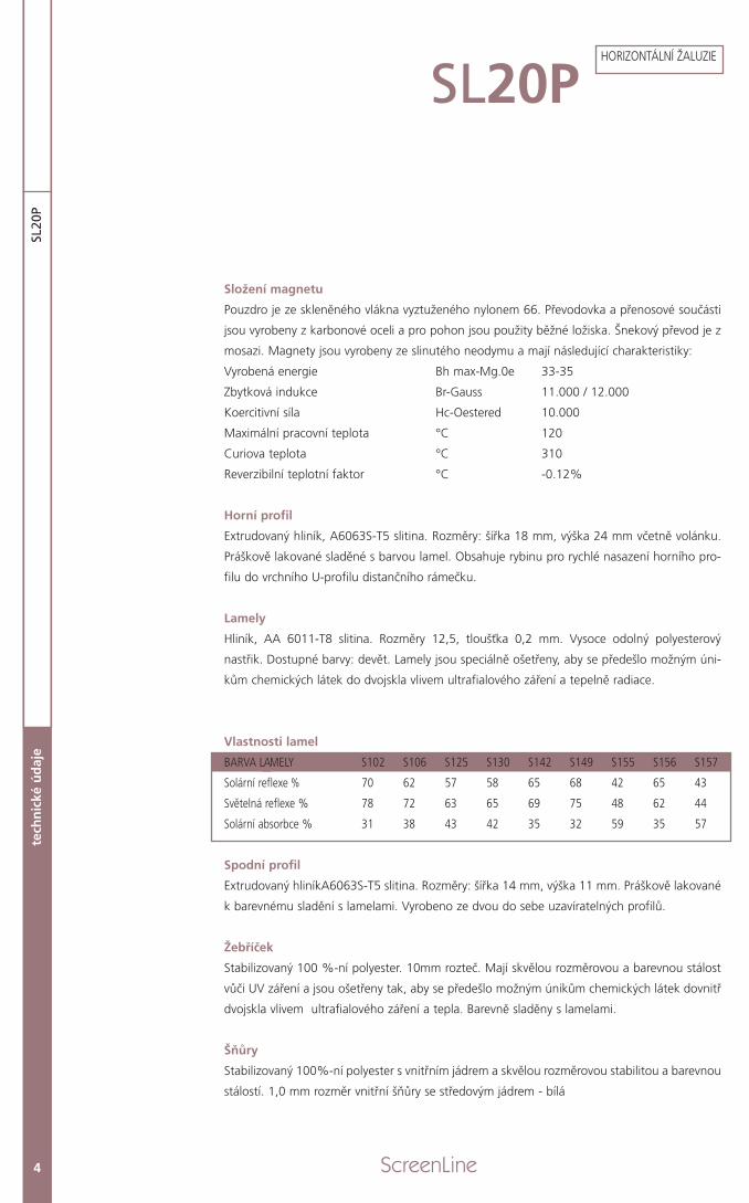
Složení magnetu
Pouzdro je ze skleněného vlákna vyztuženého nylonem 66. Převodovka a přenosové součásti
jsou vyrobeny z karbonové oceli a pro pohon jsou použity běžné ložiska. Šnekový převod je z
mosazi. Magnety jsou vyrobeny ze slinutého neodymu a mají následující charakteristiky:
Vyrobená energie Bh max-Mg.0e 33-35
Zbytková indukce Br-Gauss 11.000 / 12.000
Koercitivní síla Hc-Oestered 10.000
Maximální pracovní teplota °C 120
Curiova teplota °C 310
Reverzibilní teplotní faktor °C -0.12%
Horní profil
Extrudovaný hliník, A6063S-T5 slitina. Rozměry: šířka 18 mm, výška 24 mm včetně volánku.
Práškově lakované sladěné s barvou lamel. Obsahuje rybinu pro rychlé nasazení horního pro-
filu do vrchního U-profilu distančního rámečku.
Lamely
Hliník, AA 6011-T8 slitina. Rozměry 12,5, tloušťka 0,2 mm. Vysoce odolný polyesterový
nastřik. Dostupné barvy: devět. Lamely jsou speciálně ošetřeny, aby se předešlo možným úni-
kům chemických látek do dvojskla vlivem ultrafialového záření a tepelně radiace.
Vlastnosti lamel
BARVA LEMELY S102 S106 S125 S130 S142 S149 S155 S156 S157
Solární reflexe % 70 62 57 58 65 68 42 65 43
Světelná reflexe % 78 72 63 65 69 75 48 62 44
Solární absorbce % 31 38 43 42 35 32 59 35 57
Spodní profil
Extrudovaný hliníkA6063S-T5 slitina. Rozměry: šířka 14 mm, výška 11 mm. Práškově lakované
k barevnému sladění s lamelami. Vyrobeno ze dvou do sebe uzavíratelných profilů.
Žebříček
Stabilizovaný 100 %-ní polyester. 10mm rozteč. Mají skvělou rozměrovou a barevnou stálost
vůči UV záření a jsou ošetřeny tak, aby se předešlo možným únikům chemických látek dovnitř
dvojskla vlivem ultrafialového záření a tepla. Barevně sladěny s lamelami.
Šňůry
Stabilizovaný 100%-ní polyester s vnitřním jádrem a skvělou rozměrovou stabilitou a barevnou
stálostí. 1,0 mm rozměr vnitřní šňůry se středovým jádrem - bílá
tech
nic
ké ú
daj
eSL
20P
HORIZONTÁLNÍ ŽALUZIE
ScreenLine4
SL20P
Složení magnetu
Pouzdro je ze skleněného vlákna vyztuženého nylonem 66. Převodovka a přenosové součásti
jsou vyrobeny z karbonové oceli a pro pohon jsou použity běžné ložiska. Šnekový převod je z
mosazi. Magnety jsou vyrobeny ze slinutého neodymu a mají následující charakteristiky:
Vyrobená energie Bh max-Mg.0e 33-35
Zbytková indukce Br-Gauss 11.000 / 12.000
Koercitivní síla Hc-Oestered 10.000
Maximální pracovní teplota °C 120
Curiova teplota °C 310
Reverzibilní teplotní faktor °C -0.12%
Horní profil
Extrudovaný hliník, A6063S-T5 slitina. Rozměry: šířka 18 mm, výška 24 mm včetně volánku.
Práškově lakované sladěné s barvou lamel. Obsahuje rybinu pro rychlé nasazení horního pro-
filu do vrchního U-profilu distančního rámečku.
Lamely
Hliník, AA 6011-T8 slitina. Rozměry 12,5, tloušťka 0,2 mm. Vysoce odolný polyesterový
nastřik. Dostupné barvy: devět. Lamely jsou speciálně ošetřeny, aby se předešlo možným úni-
kům chemických látek do dvojskla vlivem ultrafialového záření a tepelně radiace.
Vlastnosti lamel
BARVA LEMELY S102 S106 S125 S130 S142 S149 S155 S156 S157
Solární reflexe % 70 62 57 58 65 68 42 65 43
Světelná reflexe % 78 72 63 65 69 75 48 62 44
Solární absorbce % 31 38 43 42 35 32 59 35 57
Spodní profil
Extrudovaný hliníkA6063S-T5 slitina. Rozměry: šířka 14 mm, výška 11 mm. Práškově lakované
k barevnému sladění s lamelami. Vyrobeno ze dvou do sebe uzavíratelných profilů.
Žebříček
Stabilizovaný 100 %-ní polyester. 10mm rozteč. Mají skvělou rozměrovou a barevnou stálost
vůči UV záření a jsou ošetřeny tak, aby se předešlo možným únikům chemických látek dovnitř
dvojskla vlivem ultrafialového záření a tepla. Barevně sladěny s lamelami.
Šňůry
Stabilizovaný 100%-ní polyester s vnitřním jádrem a skvělou rozměrovou stabilitou a barevnou
stálostí. 1,0 mm rozměr vnitřní šňůry se středovým jádrem - bílá
tech
nic
ké ú
daj
eSL
20P
HORIZONTÁLNÍ ŽALUZIE
technické údaje
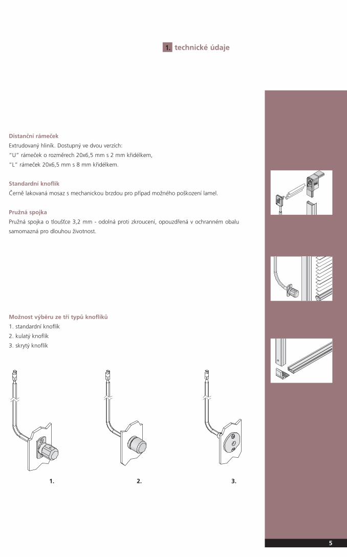
Distanční rámeček
Extrudovaný hliník. Dostupný ve dvou verzích:
“U” rámeček o rozměrech 20x6,5 mm s 2 mm křidélkem,
“L” rámeček 20x6,5 mm s 8 mm křidélkem.
Standardní knoflík
Černě lakovaná mosaz s mechanickou brzdou pro případ možného poškození lamel.
Pružná spojka
Pružná spojka o tloušťce 3,2 mm - odolná proti zkroucení, opouzdřená v ochranném obalu
samomazná pro dlouhou životnost.
5
1.
Možnost výběru ze tří typů knoflíků
1. standardní knoflík
2. kulatý knoflík
3. skrytý knoflík
1. 2. 3.
6 ScreenLine
SL20
PSL
20P
rozl
ož e
né
sch
éma
SL20P2. rozložené schéma
horiz
ontá
lní ž
aluz
ie
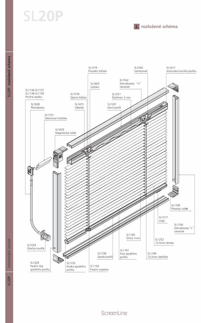
SL1136-SL1137SL1138-SL1139Pružná spojka
SL1628Převodovka
SL1723Silikonová trubička
SL1629Magnetický rožek
SL1024Otočný knoflík
SL1029Fixační čepspodního profilu
SL1021Šestihran 3 mm
SL1415Váleček
SL1603Ložisko
SL1578Spona ložiska
SL1579Pouzdro ložiska
SL1042Vymezovač
SL1542Extrudovaný “U”rámeček
SL1217Logo
SL125212,5mm lamela
SL1740Extrudovaný “L”rámeček
SL119912,5mm žebříček
SL1165Šňůra 1mm
SL1197Kryt spodníhoprofilu
SL1196 Spodní profil
SL1154 Fixační ucpávka
SL1155 Krytka spodníhoprofilu
SL1708Plastový rožec
SL1537Horní profil
SL1617Koncovka horního profilu
k
ScreenLine 7
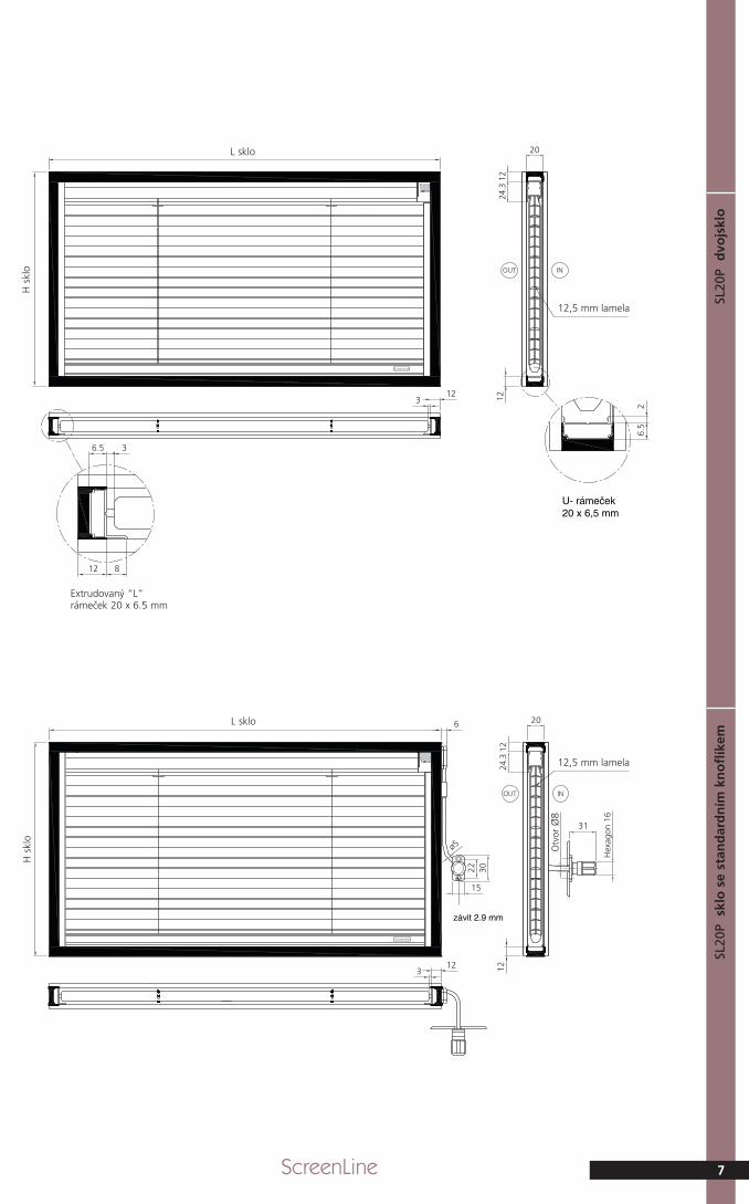
SL20
Pdvo
jsklo
SL20
Psk
lo s
e st
and
ard
ním
kn
ofl
íkem
12,5 mm lamela
Extrudovaný “L”rámeček 20 x 6.5 mm
12,5 mm lamela
L sklo
H s
klo
L sklo
H s
klo
Otvory
Otv
orØ
8
závit 2.9 mm
SL20
Pve
tro
cam
era
con
po
mo
lo t
on
do
SL20
Pve
tro
cam
era
con
po
mo
lo a
sco
mp
arsa
8 ScreenLine
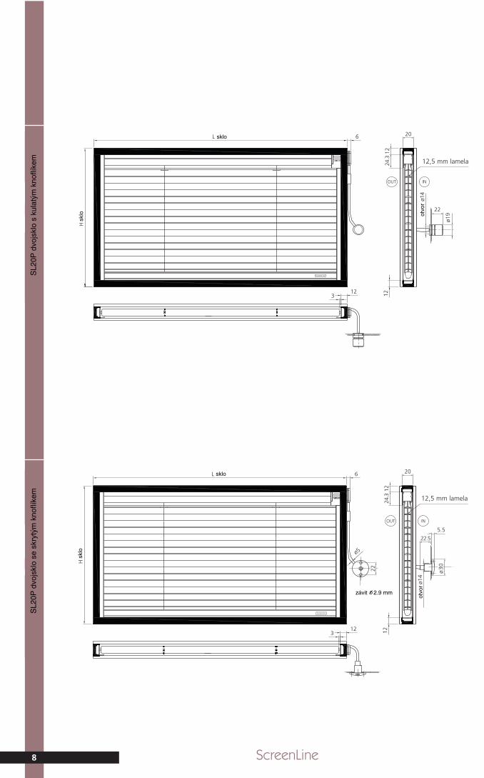
12,5 mm lamela
12,5 mm lamela
SL2
0P d
vojs
klo
s ku
latý
m k
noflí
kem
SL2
0P d
vojs
klo
se s
kryt
ým k
noflí
kem
závit 2.9 mm
otvo
r
9
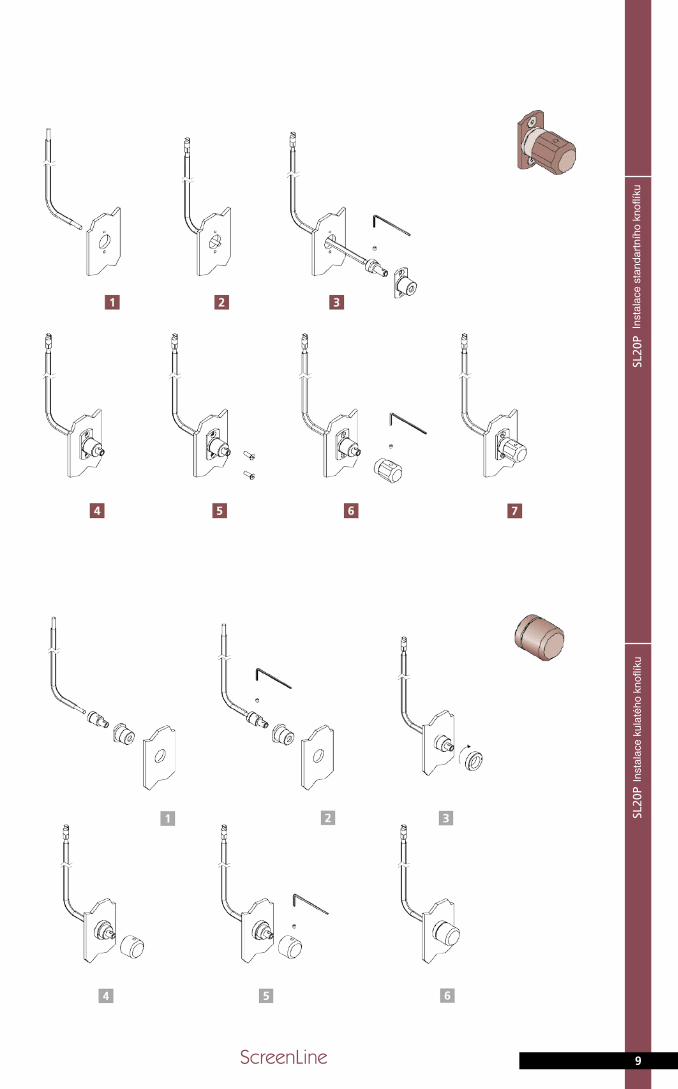
SL20
Pstan
dardkn
obassembly
SL20
Proundkn
obassembly
ScreenLine
Inst
alac
e st
anda
rtní
ho k
noflí
kuIn
stal
ace
kula
tého
kno
flíku
SL20
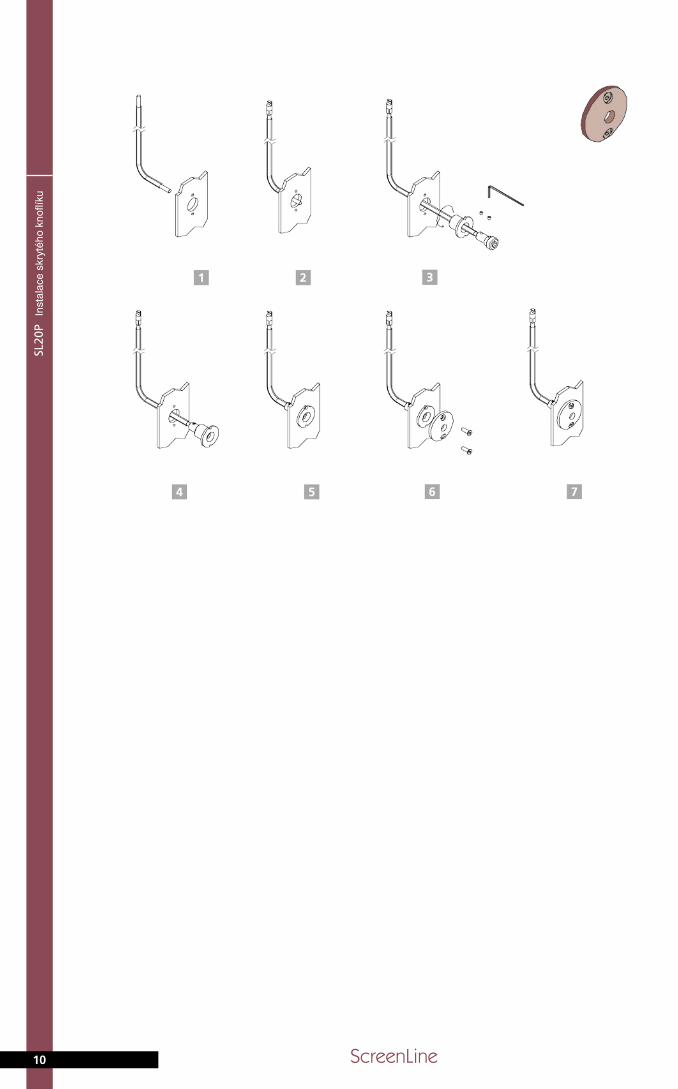
Phidden
knobassembly
10 ScreenLine
Inst
alac
e sk
ryté
ho k
noflí
ku
feasibility3.
11
double-glazedunitsizes
SL20P
30
40
50
60
70
80
90
100
110
120
130
140
150
160
170
180
190
200
210
220
230
240
250
22 30 40 50 60 70 80 90 100 110 120 130 140 150 160 170 180 190 200
Width cm
Hei
ght
cm
WH
Feasible Not feasible
Roz
měr
y dv
ojsk
la
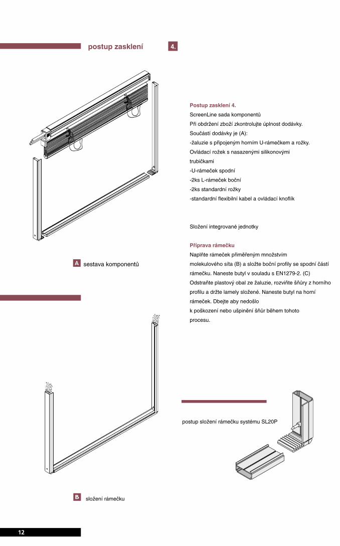
ScreenLine® kit components
On receipt of goods, check integrity of package and confirm
components as detailed on Purchase Order.
The elements of the kit comprise:
• venetian blind with head-rail / top “U” shaped spacer bar
(attached) / special corner keys (one with flexible coupling)
altogether with factory applied silicon tubes (three)
• 1 No. ”U” shaped bottom spacer bar
• 2 No. standard L-profile spacer bar with ‘pins’ factory fixed
(height)
• 2 No. standard corner keys
• standard knob control complete with flexible cable, flexible
cable cover and connection.
Assembly of the integral blind unit
Spacer bar preparation
Fill the spacer bars with the requisite amount of molecular
sieve -, assemble together ensuring that the L-profile side
spacer bars correctly interlock with the bottom spacer bar, and
then after packing the spacer to prevent desiccant loss, butyl
the three spacer bars in accordance with EN 1279-2.
Remove the plastic wrap from the head-rail / blind, unwind the
cords from the head-rail and keeping the slats stacked, butyl
the top spacer avoiding damage or contamination to the cords
during this process.
assembly instructions
12
4.
kit composition
spacer assembly
assembly procedure of the spacer bar,
SL20P system
postup zasklení
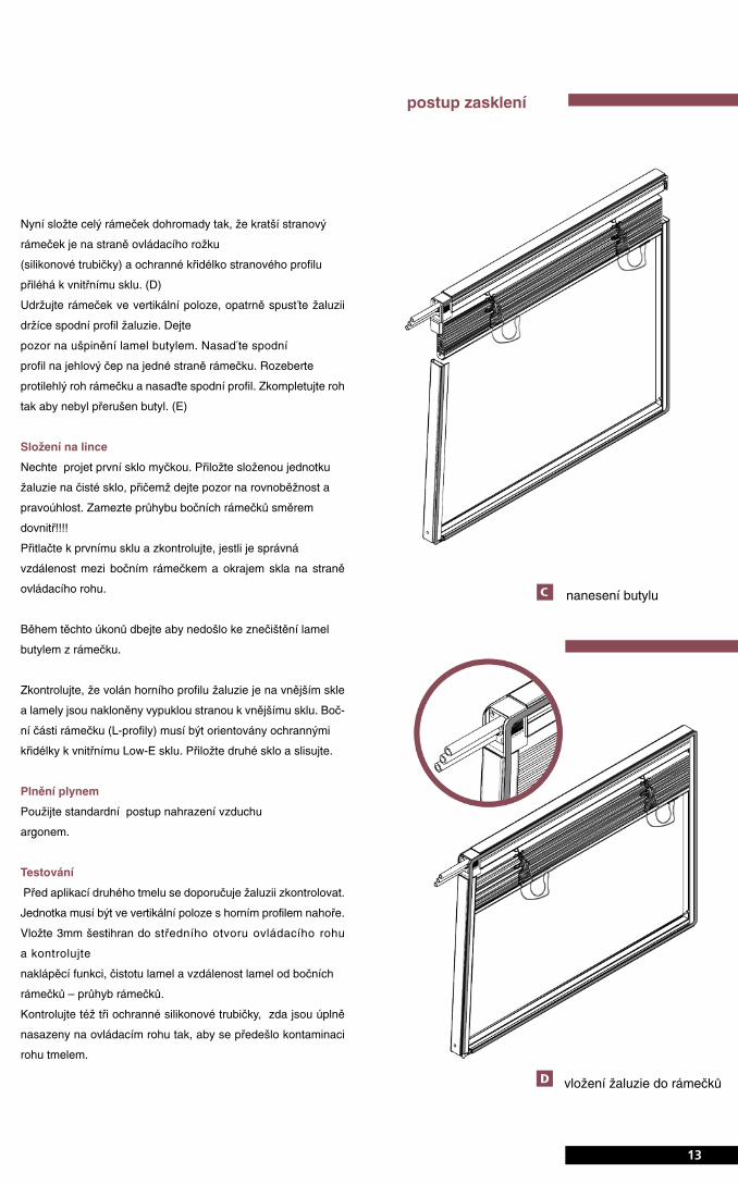
Now assemble all the spacer bars to form the complete spac-
er frame whilst ensuring that the smallest side spacer bar is
attached to the blind control corner key (silicon tubes side) and
the L-profile of the side spacer is to the inner glass.
Keeping the spacer frame vertical, lower the blind carefully by
holding and guiding the bottom rail, taking care not to dam-
age or contaminate the slats with butyl. Insert the bottom rail
onto the retaining ‘pin’ one side of the unit.
Open the corner key in the opposite corner, locate the bottom
rail on the second restraining ‘pin’ and then close the corner
key taking care to complete the butyl seal.
Line assembly
Pass the first glass through the washer on its base.
Position the assembled blind and spacer frame on the first
clean glass and ensure that it is parallel and square (no inner
deflection of the vertical spacers). Press firmly to achieve good
adhesion and check that there is the correct clearance
between the vertical spacer and the edge of the glass on the
‘wire’ drive side.
During this operation avoid contact / contamination between
slats and the butyl of the spacer bars.
Ensure that the pelmet of the head rail is positioned against
the external glass and that the slats are closed convex to the
external glass. The L-profile of the side spacer bars should be
to the inner glass (low ’E’) surface. Now assemble the clean
second glass and pass through the press.
Gas filling
Following standard procedure replace the internal air with
Argon.
Test
Prior to the final sealing it is recommended that the blind oper-
ation is checked. The unit must be vertical with the head-rail
horizontal at the top of the unit. Insert a 3 mm dia. hexagonal
spanner (Allen Key) in the central recess of the control corner
key and check the tilting function of the slats and that the slat
clearance with the spacer bar is uniform.
Ensure that the three protective silicon tubes are present on
the connections of the magnetic corner key (drive shaft and
screw locations), in order to protect these parts during the sec-
ond sealing.
assembly instructions
13
unit first sealing
insertion of the blind into
the spacer bars
postup zasklení
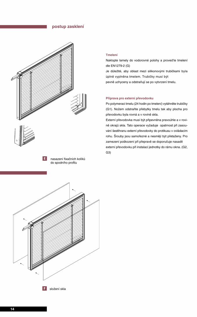
Final seal
Rotate the slats to their mid-position i.e. open, and apply the
final seal in accordance with EN 1279-2.
It is essential that the area around the wire drive connection
(near the silicon tubes) is fully enclosed with sealant (addition-
al sealant may be added by hand if necessary). The silicon
tubes should be firmly fixed and must only be removed once
the secondary sealant is cured.
Preparation for the external control
After polymerisation of the sealant (at least after 24 hours after
the sealing procedure) remove (pull off) the silicon tubes.
With a blade remove any excess sealant where the tubes have
been located, in order to ensure a level surface for fixing the
external drive connection.
The external drive connection should then be positioned and
attached square and level on the unit edge. This operation
requires a particular care when centring the hexagonal pin of
the wire drive attachment.
The fixing screws are self-tapping and should not be over-
tightened. To avoid possible damage during the transporta-
tion, it is recommended that the wire drive and knob control
mechanism is fitted during the IG unit installation inside the
frame and .
assembly instructions
14
position the restraining pins
into the bottom rail
glass assembling
postup zasklení
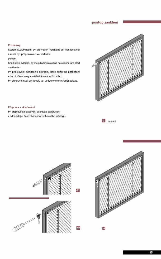
Note
SL20P systems must not be inverted (vertically or horizontally)
and should only be stored or moved in the vertical plane.
The knob control system should be in place on the window
frame prior to or during glazing.
When connecting the flexible cable to the wire drive mecha-
nism take care not to damage the drive mechanism.
The transport of the integrated system must be done with the
slat in open position to avoid slat contamination by the pri-
mary butyl seal which could result in ‘sticking’ slats.
Transport and Storage
For transport and storage procedure please check the recom-
mendations contained in the relevant part of the ScreenLine®
Technical Catalogue.
assembly instructions
15
unit second sealing
postup zasklení
tmelení
Pelli
niS.p.A.viaFu
sari,19
•26
845Codogno(LO)ITALIA
T.+39
0377
4664
11•F.+39
0377
4376
35•info@pellin
i.net
SL20
PMTL
003
Edition07
.06
www.pellini.net
visual
design:stefan
osiboni.it
VY
DÁ
NÍ
www.screenline.cz
Scr
eenl
ine
CZ
a.s
., B
ratis
lavs
ká 1
/6, 6
95 0
1 H
odon
ín, C
Z+
420
518
343
614
F.
+ 4
20 5
18 3
43 6
13