Embed Size (px)
Citation preview

KKKAAARRRAAACCCHHHIII WWWAAATTTEEERRR &&& SSSEEEWWWEEERRRAAAGGGEEE BBBOOOAAARRRDDD
PPPRRROOOJJJEEECCCTTT:::
CCCOOONNNSSSTTTRRRUUUCCCTTTIIIOOONNN OOOFFF
NNNEEEWWW 111000000 MMMGGGDDD PPPUUUMMMPPP HHHOOOUUUSSSEEE
(((EEEQQQUUUIIIPPPPPPEEEDDD WWWIIITTTHHH MMM &&& EEE PPPUUUMMMPPPIIINNNGGG MMMAAACCCHHHIIINNNEEERRRIIIEEESSS)))
AAATTT DDDHHHAAABBBEEEJJJIII
EEEPPPCCC/// TTTUUURRRNNNKKKEEEYYY CCCOOONNNTTTRRRAAACCCTTT
OOONNN LLLUUUMMMPPP SSSUUUMMM FFFIIIXXXEEEDDD PPPRRRIIICCCEEEBBBAAASSSIIISSS
BBBIIIDDDDDDIIINNNGGG DDDOOOCCCUUUMMMEEENNNTTT (((VVVOOOLLLUUUMMMEEE---IIIIII)))
SSSPPPEEECCCIIIFFFIIICCCAAATTTIIIOOONNN ––– TTTEEECCCHHHNNNIIICCCAAALLL PPPRRROOOVVVIIISSSIIIOOONNN
EEEMMMPPPLLLOOOYYYEEERRR’’’SSS RRREEEQQQUUUIIIRRREEEMMMEEENNNTTTSSS FFFOOORRR
CCCIIIVVVIIILLL,,, MMMEEECCCHHHAAANNNIIICCCAAALLL &&& EEELLLEEECCCTTTRRRIIICCCAAALLL WWWOOORRRKKKSSS
FFEEBBRRUUAARRYY 22001166
CCOONNSSUULLTTAANNTT
OOSSMMAANNII && CCOOMMPPAANNYY ((PPVVTT..)) LLTTDD.. CCoonnssuullttiinngg EEnnggiinneeeerriinngg -- AArrcchhiitteeccttss -- PPllaannnneerrss
OOssmmaannii HHoouussee,, 224455//22--KK,, BBlloocckk--66,, PPEECCHHSS,, KKaarraacchhii
TTeell:: ((9922--2211)) 3344553366000077--0088,, 3344554466554411--4422,, FFaaxx:: ((9922--2211)) 3344553344669911
EE--mmaaiill:: ooccll--kkhhii@@oossmmaannii..ccoomm WWeebb:: wwwwww..oossmmaannii..ccoomm
Issued to M/s: __________________
Date: ________________________
Issued By: ____________________

KKKAAARRRAAACCCHHHIII WWWAAATTTEEERRR &&& SSSEEEWWWEEERRRAAAGGGEEE BBBOOOAAARRRDDD
TTTAAABBBLLLEEE OOOFFF CCCOOONNNTTTEEENNNTTTSSS
VVOOLLUUMMEE -- II
BIDDING DOCUMENTS
VVOOLLUUMMEE -- IIII
1. SPECIFICATIONS -TECHNICAL PROVISIONS - ELECTRICAL & MECHANICAL
2. SPECIFICATIONS - TECHNICAL PROVISIONS – CIVIL
VVOOLLUUMMEE -- IIIIII
BIDDING DRAWINGS

KKAARRAACCHHII WWAATTEERR && SSEEWWEERRAAGGEE BBOOAARRDD
TTAABBLLEE OOFF CCOONNTTEENNTTSS
VVOOLLUUMMEE--IIII ((11))
EEMMPPLLOOYYEERR’’SS RREEQQUUIIRREEMMEENNTTSS
FFOORR
MMEECCHHAANNIICCAALL && EELLEECCTTRRIICCAALL WWOORRKKSS
CChhaapptteerr--0011:: GGeenneerraall RReeqquuiirreemmeennttss
CChhaapptteerr--0022:: MMeecchhaanniiccaall && EElleeccttrriiccaall PPllaannttss
CChhaapptteerr--0033:: GGeenneerraall TTeessttiinngg,, IInnssppeeccttiioonn,, CCoommmmiissssiioonniinngg aanndd TTrraaiinniinngg
CChhaapptteerr--0044:: MMeecchhaanniiccaall WWoorrkkss
CChhaapptteerr--0055:: EElleeccttrriiccaall WWoorrkkss
CChhaapptteerr--0066:: PPaaiinnttiinngg aanndd PPrrootteeccttiioonn
CChhaapptteerr--0077:: WWoorrkk IItteemmss
CChhaapptteerr--0088:: SScchheedduullee ooff GGuuaarraanntteeeess
VVOOLLUUMMEE--IIII ((22))
EEMMPPLLOOYYEERR’’SS RREEQQUUIIRREEMMEENNTTSS
FFOORR
CCIIVVIILL WWOORRKKSS
CChhaapptteerr 0099:: CCiivviill WWoorrkkss -- SSccooppee ooff WWoorrkk
CChhaapptteerr 1100:: CCiivviill WWoorrkkss -- EEmmppllooyyeerrss RReeqquuiirreemmeennttss

KKAARRAACCHHII WWAATTEERR && SSEEWWEERRAAGGEE BBOOAARRDD
TTAABBLLEE OOFF CCOONNTTEENNTTSS
VVOOLLUUMMEE--IIII ((11))
EEMMPPLLOOYYEERR’’SS RREEQQUUIIRREEMMEENNTTSS
FFOORR
MMEECCHHAANNIICCAALL && EELLEECCTTRRIICCAALL WWOORRKKSS
CChhaapptteerr--0011:: GGeenneerraall RReeqquuiirreemmeennttss
CChhaapptteerr--0022:: MMeecchhaanniiccaall && EElleeccttrriiccaall PPllaannttss
CChhaapptteerr--0033:: GGeenneerraall TTeessttiinngg,, IInnssppeeccttiioonn,, CCoommmmiissssiioonniinngg aanndd TTrraaiinniinngg
CChhaapptteerr--0044:: MMeecchhaanniiccaall WWoorrkkss
CChhaapptteerr--0055:: EElleeccttrriiccaall WWoorrkkss
CChhaapptteerr--0066:: PPaaiinnttiinngg aanndd PPrrootteeccttiioonn
CChhaapptteerr--0077:: WWoorrkk IItteemmss
CChhaapptteerr--0088:: SScchheedduullee ooff GGuuaarraanntteeeess
EMPLOYER’S REQUIRMENT FOR MECHANICAL & ELECTRICAL WORKS
CHAPTER 01 GENERAL REQUIREMENTS
CHAPTER 1
GENERAL REQUIREMENTS
TABLE OF CONTENTS
1.1. General .......................................................................................................................... 1 1.2. Background and Project Objectives .............................................................................. 1 1.3. Works to be executed on “EPC/Turnkey” basis ........................................................... 2 1.4. Units of Measurement ................................................................................................... 3 1.5. Language of Usage ....................................................................................................... 3 1.6. Operational Capacity of Pumping Stations ................................................................... 3 1.7. Plant Design .................................................................................................................. 3 1.8. Regulations and Standard Specifications ...................................................................... 4 1.9. Project Management ..................................................................................................... 4 1.10. Water for Testing and Commissioning of Plant............................................................ 5 1.11. Permanent Power Supply .............................................................................................. 5 1.12. Drawings ....................................................................................................................... 5 1.13. Bid submissions .......................................................................................................... 10
1.13.1 Design brief ............................................................................................................... 10 1.13.2 Construction Specifications ....................................................................................... 10 1.13.3 Contractor staff qualification ..................................................................................... 10
1.14. Detailed design submission......................................................................................... 10 1.14.1 Design Programme .................................................................................................... 10 1.14.2 Detailed design submission ....................................................................................... 11 1.14.3 Drawings & documents ............................................................................................. 11 1.14.4 Submission Drawings ................................................................................................ 12 1.14.5 Approved drawings .................................................................................................... 13 1.14.6 Amendment / revision of drawings ............................................................................ 13 1.14.7 Defect......................................................................................................................... 13 1.14.8 Consent or approval ................................................................................................... 14
1.15. Transport for the Employer ......................................................................................... 14 1.16. Telephones .................................................................................................................. 15 1.17. Health and Safety ........................................................................................................ 15 1.18. Operation and Maintenance Manuals ......................................................................... 15 1.19. Commissioning and Reliability Trials ........................................................................ 18 1.20. Inspection and Tests .................................................................................................... 19 1.21. Warranty Period .......................................................................................................... 20 1.22. Plant Delivery and Handling ....................................................................................... 20
1.22.1 Protection and packing for dispatch ........................................................................... 20 1.22.2 Safekeeping and Storage ............................................................................................ 22
1.23. Unloading, erection and running of equipment .......................................................... 22 1.24. Equipment spare parts ................................................................................................. 23 1.25. Special tools and testing equipments .......................................................................... 24 1.26. After – Sales Service ................................................................................................... 24 1.27. Cleaning of Plant ........................................................................................................ 24

Chapter: 01 - General Requirements CH 1-1
CHAPTER 1 GENERAL REQUIREMENTS
1.1. General
Volume-II of the Tender Documents contains Employer general requirements and Minimum standards of design, materials & workmanship of the work with respect to all Mechanical, Electrical and Civil Works of the Pump House to be constructed on EPC/Turnkey basis. In case of any conflict between provisions of Chapters 1, 2, 3, 4, 5, and 6, the later shall take precedence. Chapter 1 of this Volume includes some of the general responsibilities for execution of the Work, which are in addition to the requirements provided in the Conditions of Contract, Volume-I.
1.2. Background and Project Objectives
a) Background After partition in 1947, the city of Karachi population started increasing rapidly due to heavy influx of refugees from India and people migrating to Karachi from upcountry. Because of this, the water supply from Haleji Lake and Dumlotte wells was insufficient to meet the increasing water demand. Due to non-availability of any other source close to the city, the Government of Pakistan allocated Indus water for meeting city water requirements. To utilize this allocation, the Greater Bulk Water Supply Scheme was approved in early 1950s for bringing the allocated water in 4 Phases, which have since been completed under Greater Karachi Bulk Water Supply system, K-I comprising 4 phases K-I Project. The K-I scheme which supplies 280 MGD water was completed in four equal phases in 1959, 1971, 1976 and 1994, respectively. K-I scheme consists of bringing Indus water to Kinjhar Lake through an irrigation canal and the settled water of the lake is then conveyed to Dhabeji (which is almost at sea level) through the KWSB canal. This water is lifted to about 60 meter elevation at Dhabeji and is then gravitated to Karachi through a system of covered conduits and syphons.
Phase - I K-I system, originally had 5 pumping units each of 109,000 m3/day (24 MGD) capacity with three working and two standbys. The Pumping machinery comprises of single stage vertical dry pit pumps driven by diesel engines. The power is transmitted to the pumps through right angle bevel geared heads. All the components of the pump sets have outlived their useful and economic operational life and are working at reduced capacity due to frequent break downs and loss of efficiencies. One diesel engine has gone out of service while others need replacements. Some load of this pump house has been transferred to the other three phases by operating their standbys. The output of these three pump houses has also reduced considerably because of efficiency loss aggravated by intermittent cavitation problems.

Chapter: 01 - General Requirements CH 1-2
In view of above, it has been decided that this pump house should be replaced by a new pump house of 464,600 m3/day (100 MGD) capacity by providing six electric motor driven pumps (4 Working and 2 Standbys) each of 114,000 m3/day (25 MGD) output rating. It will not only elevate the existing situation but will relieve the pressure on the existing reduced water supplies.’
b) Project Objectives
The objectives of the EPC/Turnkey Contract is the provision of a high lift Pumping Station of 464,600 m3/day (100 MGD) capacity at Dhabeji to replace the existing Phase-I pump house of (327,312 m3/d) 72 MGD output rating built and commissioned in 1959.
The EPC/Turnkey work includes design and construction of all Civil Works, Procurement, Installation, Erection, Testing and Commissioning of all Electrical and Mechanical Works, equipment and service and ancillary maintenance training of operatives all as detailed in the Tender documents.
The pump house will comprise of: (1) All civil works of the pump house including inlet works, screen
channels and chambers etc. (2) Sump model test. (3) Manual and automatic bar screens. (4) Mechanically operated band screens (5) High lift pumping sets (6) Transformers (7) HV and LV panels (8) PLC/SCADA system for auto control, monitoring and data
processing (9) Suction and discharge pipework and delivery manifold including
valves and flow meter in each pump. (10) Surge control system (11) Flow meter (12) Internal and external illumination including emergency lighting (13) Overhead gantry crane (14) Exhaust fans (15) Any other work to complete the project objective (16) Outer development including landscaping (17) Penstocks (18) Level sensors (19) HT/LT power cables
1.3. Works to be executed on “EPC/Turnkey” basis
The Contract is for the engineering designs, supply and execution of civil, mechanical and electrical works of the pumping station on “EPC/Turnkey (Engineering, Procurement and Construction) Turnkey” basis as stated in the Contract.

Chapter: 01 - General Requirements CH 1-3
The electrical and mechanical works include complete designs, manufacture of plant and equipment testing at manufacture’s works, painting and full tropicalization, packing, freight and port handling including making all arrangements for clearance of imported goods, preparation of bill of entries and all other documents for port clearance, issue of import permits etc. and assessment of duty and taxes. The Contract also includes payment of wharfage, demurrage, octroi, clearance charges, toll and all local/government duties, taxes and charges, insurance costs, taking charge at the port of delivery or at local manufacturer’s/supplier’s works, loading, transportation, handling at various stages, unloading, safe storage, erection, testing, site painting, commissioning, testing and operation complete in all respects of the plant and machinery for providing a pumping station of the highest possible operative standard as per Contract Specification including all other items not specifically mentioned but are necessary for the satisfactory performance of the Work. The Contract includes all costs related to the execution of the Work including provision of all skilled and unskilled labour, supervision, training of Employer's operation and maintenance personnel. Production of drawings and O&M manuals as required under the Contract.
1.4. Units of Measurement All designs, drawings, specifications and manuals shall use SI (Kg m s) units and all measurements, dimensions and performance data shall be quoted in these units.
1.5. Language of Usage
All drawings, instructions, signs, notices, name-plates etc. for use in the operation and maintenance of the completed Works shall be in English. Warning signs shall be in Urdu and English.
1.6. Operational Capacity of Pumping Stations
The new Pumping Works shall operate on a 24 hours basis with staff superintendence during 24 hours per day for 7 days per week. It shall be capable of operating at rates between 25% and 100% of design flow.
1.7. Plant Design The whole of the Plant and machinery shall be designed and constructed to the high level/latest standards of International water works practice. A manufacturer’s standard design may be used for a Plant item where such a design is not available and it is equal to and compatible with that required by the Specifications. The Plant shall be new, of sound workmanship and robust design, and of a grade and quality suitable for the duty concerned and for the climatic conditions at Site.

Chapter: 01 - General Requirements CH 1-4
The Plant shall be designed to provide adequate protection against the attack of vermin and dust and to minimize fire risk and consequential damage. All parts which can be worn or damaged by dust shall be totally enclosed in dust proof housings. All equipment’s shall operate without excessive vibration and with minimum of noise. All similar items of the Plant and their components together with spare parts shall be made from the same material and shall be fully interchangeable.
1.8. Regulations and Standard Specifications
Except where otherwise specified all materials and workmanship shall comply with current international standards provided that these standards are not less stringent than the equivalent British Standards or Codes of Practice or provided that they comply with the requirements of the International Organization for Standardization (ISO) or the International Electro-technical Commission (IEC), as appropriate. For the purpose of inspection or testing, the Contractor shall make available to the Employer copies of relevant standards. The electricity installation shall comply with all relevant statutory regulations and standards at the current date of Tender, unless, otherwise indicated within this Specification. Electrical installations shall where relevant be in accordance with the IEE Regulation for Electrical Installations, latest edition. The Contractor shall make available ANSI/HI 9.8-2012 to the Employer, 10 paper and 1 electronic copy shall be provided.
1.9. Project Management
The Contractor shall be responsible for administration of the Project from award of Contract through design, manufacture, works testing, delivery of plant to the site, installation, testing and commissioning to final taking-over. For this purpose he shall nominate a Project Manager (PM) who shall be fully responsible for and undertake the administration. The PM shall be a manager with not less than 20 years of experience of construction management at least 5 years of which is in a management position on works of a similar nature and complexity as required for this project. Specific responsibilities of the PM shall be: a. Representation on behalf of the Contractor or the Consortium of
Contractors in all discussions and matters relating to Work.
b. Coordination and monitoring Contract progress and submitting monthly progress reports.

Chapter: 01 - General Requirements CH 1-5
c. Attending periodical and/or monthly meetings called by the Employer and giving full account of the Contract progress, program of Work and Site related problems
d. Coordination and programming of all building works, installation of plant,
site tests and takeover trials including coordination of various sub-contractors employed by the contractors.
e. Preparation of training programs of Employer's personnel and coordination
of their training activities.
1.10. Water for Testing and Commissioning of Plant Water for testing and commissioning will be made available by the Employer at the commencement of the Work free of cost to the Contractor. The Contractor shall make his own arrangements for transporting the water to the civil construction Sites and other requirements at his own cost. The Contractor shall give a minimum of 30 days’ notice in writing to the Employer of when water is required for tests and commissioning.
1.11. Permanent Power Supply The Employer will provide permanent Electric supply at KESC substation as determined by the Contractor in his EPC/Turnkey Design. The Contractor shall derive power from this substation at 11kV, 3 phase, 50Hz. The electric supply will be available to the Contractor free of cost for tests and commissioning. The Contractor shall extend his connections to all switch boards at site as provided in the Specification for servicing all sections of the Plant including building services to be provided by him under the civil works of the Contract.
1.12. Drawings
a. General All drawings submitted by the Contractor to the Employer for consent shall be on ISO standard size sheets with a maximum size of A1 unless otherwise agreed. Every drawing shall have a title box in the bottom right corner showing:- (1) Employer’s Name (2) Title of Scheme (3) Title of Contract (4) Contractor’s Name (5) Title of Work Location (6) Title of Drawing (7) Drawing Number (8) Date (9) Designer

Chapter: 01 - General Requirements CH 1-6
(10) Signature of Contractor to the effect that the drawing, whether his own or from any other source has been checked by him before submission to the Employer/ employee representative.
Each drawing shall also have a separate revision box with space for revisions and including revision number, revision date, revision description and revision check. Drawings shall be drawn to specified scales or to such scales as are appropriate for clearly detailing and conveying the Contractor's proposals. Scales shall generally be 1:2, 1:5, 1:10 or multiples of 10 thereof. The appropriate measuring scales used shall be shown on the drawings. Drawings shall include cross references where appropriate and key information such as vital levels and dimensions. All plans shall show the ‘north’ direction. All drawings submitted by the Contractor shall use the English language and SI units. Where drawings shall be revised, the revision letter or number shall be incorporated in the title block and the revision shall be clearly indicated on the drawing with the revision letter or number shown in an adjacent triangle. Original drawings shall be drawn in ink. Prints of drawings shall show dark and fade-proof line work on a light and non-darkening background. Prints shall be on durable paper of good quality and 80 gm/m2 minimum weight. Reproducible shall be on 75 micron durable plastic film. CAD drawings shall be on DVDs in the latest version of AutoCAD format. Four sets of drawings and documents shall also be supplied in softcopies, DVD ROM. The drawings comprise of:- a. Conceptual Drawings
These are drawings issued to the Contractor with the Tender Documents for the purpose of preparing a tender. Such drawings shall be deemed to have been issued for the guidance of the Tenders and shall be referred to for the interpretation of the Contract only where the drawings supplied by the Contractor at the time of tendering and incorporated in the Contract are insufficient.
b. Tender Drawings
The Tender Drawings of all Civil, Mechanical and Electrical Works are to be supplied by the Contractor for the purpose of illustrating his Tender, mainly: (1) A layout of the whole scheme, in appropriate scale.

Chapter: 01 - General Requirements CH 1-7
(2) Drawings and technical details of the plant in sufficient detail to illustrate that the several items of the plant are suitable for their intended purpose.
Where Contractors tender proposals are given, Tender Drawings showing features not in compliance with the Specifications, and where such features are not listed in the Contract then the requirements of the Conceptual Drawings will be taken as the basis of the Contract.
c. Approved Drawings Within 3 months of the Commencement Date, the Contractor shall submit to the Employer, four copies of detailed drawings of all civil, electrical and mechanical works, for approval, as detailed below.
Structural detailed Drawings and Computations.
The Pump Station building and its components shall be designed to be earthquake resistant.
The drawings shall show sufficient detail and structural design of the associated civil structure, including dimensions of foundations, the detailed dimensions of channels and sizes of openings in walls etc. Detailed computation sheets for structural design shall also be submitted with the Drawings.
Manufacturing of the Plant shall not begin, nor shall erection of the Plant commence, until the appropriate Approved Drawings are available. The Plant shall be manufactured and erected in accordance with the Approved and Conceptual Drawings.
The approval by the Employer shall constitute only general approval of overall layout of Civil, Mechanical and Electrical works, nevertheless the main responsibility of proper and adequate design and functioning of the entire system of the pumping station shall rest with the contractor.
The Approved Drawings shall include but may not be limited to:
(1) General arrangement drawings to illustrate the position of the Plant in relation to the appropriate part of the Work in sufficient detail to show all the principal dimensions, methods of support and other relevant information.
(2) Drawings of the Plant in sufficient details for the Employer to satisfy himself that jointly and severally the items of the plant are suitable for their intended purpose.
(3) Sectional drawings of each major item of the Plant including general arrangement of electrical panels with foundation and cable access details.
(4) Diagrammatic outline and detail drawings of all services to, from and between the several items of the Plant, including

Chapter: 01 - General Requirements CH 1-8
water supplies, pipe work, connections and fittings, electrical single line and schematic diagrams, cable schedules and site cable layout.
(5) Requirements for incoming supplies, services and details of interface connections in respect of the Plant, particularly where such connections are at the limit of the Contract.
(6) Drawings of the Plant and data in sufficient detail as may be reasonably required by the Employer to satisfy himself as to the stability. Durability and safety of the works and for ascertaining inspection of the Plant during construction that it is in conformity with the Contract.
(7) Installation drawings giving complete dimensions of pedestals, cuts, chases, bolt holes, ducts and other provisions to be made in the civil structures and on Site during the fixing of the Plant.
d. Employer's Drawings The drawings issued from time to time by the Employer.
e. As-Built or Record Drawings The Contractor shall provide As Built or Record Drawings to show the whole of the civil works as constructed and the Plant as installed. They shall be in the form of six (06) sets of full (as drawn) reproducible plus one set of drawings in an electronic format using AUTO-CAD latest version or civil 3D or approved similar. They shall include all such drawings, diagrams and schedules as are necessary for a complete understanding of the work including details of any 'bought-in’ items and any items shown as 'blocks' on the main drawings. Information given on Record Drawings shall include tolerances, clearances, Loadings, finishes, materials and ratings. The Contractor shall ensure that the consented to Drawings are marked up to show the condition of the civil Works as constructed and the Plant as installed and two copies of such marked up prints shall be submitted to the Employer for consent prior to the preparation of Record Drawings and to the start of tests before completion. Record Drawings shall include but not limited to -
1) Process and instrumentation (P&I) diagrams showing in symbolic form the plant and systems for measurement, control and automation Including interface between control panels and separate installations etc.
2) General arrangement of drawings and sectional views, fully dimensioned and showing in detail all items of plant and ancillary equipment to be provided under the Contract.

Chapter: 01 - General Requirements CH 1-9
3) Dimensional assembly and erection drawings of each item of Plant.
4) Foundation drawing showing foundation requirement for Plant and loads thereon. This shall include all holes, chases and other requirements to building structure required for the installation of the Plant.
5) Working drawings of all engineering systems requiring electrical and /or mechanical connections. Showing the units of equipment in the proposed position for installation and the details of attachment and connections required, with locations referred to each other and to the structure.
6) Diagrams of connections for each type of electrical equipment together with a comprehensive wiring diagram showing all connections between the various items of the equipment and the safety devices (the terminal lettering shall correspond to the terminal marking to be used on the equipment).
7) Surge valves, control valves, protection from water hammers, and failure of one pump or all the pumps. Power failures and equipment protection devices.
8) Working drawings for protection and air-conditioning systems and for water supply, drainage, waste water and firefighting systems.
9) Plans of conduits, station pipe work and valves indicating manual and remote control devices.
10) Fabrication drawings for station metal work, including platforms, floor plates and frames, handrailings etc.
11) Diagrams showing flow paths and circuits and piezometric levels corresponding to average and maximum flow rates accompanied by proof of computations.
12) Complete and detailed schedules listing all items of plant and ancillary equipment to be supplied by the Contractor.
13) Civil works drawings (liaison, markup and correction to the civil contractor design as necessary to facilitate the integration of the M & E and civil systems).
14) Any additional drawings required to cover other elements not listed above.
All items of electrical equipment constituting an operating system and any mechanical units involved therein or necessary for the functioning of such system shall be submitted to the Employer concurrently and shall include clear diagrams showing circuit functioning and necessary details for field erection.

Chapter: 01 - General Requirements CH 1-10
1.13. Bid submissions 1.13.1 Design brief
a) General
Clause 7.1 of Material & Workmanship defines the scope of work. The Employer requires that each bidder be prepared to define in detail, the elements of his offer during the tendering process. This shall be done through a design brief covering all elements to be designed by Contractor. Through this brief the contractor shall provide evidence that consideration has been given to all other items. The design brief is to be supported by drawings and are intended to represent the type and quality of information required to evaluate the bids and to highlight; (1) Design parameters and methodology (2) Design criteria of the project and its components parts.
1.13.2 Construction Specifications
All designs, equipment materials and construction methodology not completely detailed in referenced or proposed documents or design criteria shall conform to acceptable industrial practice. During the evaluation period, the Employer may request to submit Construction Specifications for the purpose of clarifying and defining the bid. The format of the Specifications shall be as follows:
a. General b. Detail Description c. Related Works d. Reference Specifications e. Submittals f. Design Requirements
1.13.3 Contractor staff qualification
All staff must be proficient in the English language. The Project Manager, Project Design Manager and Project Design Engineer should be graduates of recognized colleges. The Bidders shall submit with their Bids the name of the nominees for each of the designated positions together with detailed resumes of their experience and qualifications.
1.14. Detailed design submission
1.14.1 Design Programme The Contractor shall submit to the Employer a Design Programme showing the order and procedure in which he proposes to carry out the Design and Engineering services with a schedule of submission of design documents and drawings for completing the Works within 28 days after the “Notice to Commence”, and also to match with the Work Programme (Sub-Clause 8.3 of

Chapter: 01 - General Requirements CH 1-11
the Conditions of Contract). Such Design Programme shall be subject to review and revision by the Contractor in Consultation with the Employer in order to achieve completion of the Works within the time for completion.
The number of copies of the report and other documents to be submitted to the Employer by the Contractor is specified in Sub-Clause 2.8. 1.14.2 Detailed design submission
The Contractor shall carry out structural analysis of the structures and its foundations to confirm the stability under site specific seismic loads.
Detailed reinforcement drawings and bar bending schedules shall be prepared for all concrete structures. Where the structural design for earthquake loading relies in ductile behavior of structural elements then anchorage, splicing of bars and shear provision shall comply with current earthquake detailing practice.
The design works shall cover determining the hydraulic conditions relevant for long term operational efficiency and safety in the approach to through all water conveyance elements. Within 2 (two) months of commencement date and prior to beginning any construction work, the Contractor shall submit to Employer for consent a Detailed Project Report (DPR). The DPR shall define all finished structural dimensions and / or performance characteristic of all elements of the project except those dependent on subsurface geotechnical conditions. Geotechnical investigation report is enclosed. The bidder however shall ensure that the estimates are based on the Contractor’s own confirmatory investigations and / or interpretations. The results and interpretations of the geotechnical investigations shall be presented in the DPR.
The DPR should include at least the following: a. The result and interpretations of the geotechnical investigations (including
construction materials.) b. The results and interpretations of the hydrological investigations. c. The results and interpretations of topographic surveys. d. The geotechnical, hydraulic and structural design including design
standards, criteria and calculations. e. Drawings to a detail sufficient to show all significant structural and plant
features. f. Justifications supported by calculations and drawings. g. Details of specifications to be adopted. h. Quality Control plan for construction stage.
1.14.3 Drawings & documents
The contractor shall provide copies of all standard mentioned in this document. Furthermore all standards referred to in the design documents submitted by the EPC contractor shall also be provided to the employer. All standards copies shall be provided. As a part of the Design Documentation,

Chapter: 01 - General Requirements CH 1-12
the Contractor shall provide a complete and clear set of stability check calculations, specifications and drawings of all construction works, service utilities, and materials as well as of his temporary works design. The Contractor shall successively submit structural design, documents and drawings for the review, comment and consent of the Employers in accordance with the schedule of submission of design documents and drawings in the Contractor’s Work Programme as stipulated in above. The Employer shall give his consent / Comments on all design and drawings referred to him within 15 days for submissions prepared by the Contractor and submitted to the Employer at Site, and 28 days of the date of receipt in the Employer main design office for submissions prepared by the Contractor and reviewed by the Employer from the main design offices.
1.14.4 Submission Drawings The details of drawings / documents which will be submitted for the Employer review and consent or for information are as below:
a. Detailed technical specifications wherever necessary. b. General arrangement and layout drawings. c. Concrete outline drawings. d. Assembly drawings. e. Foundation design and treatment drawings. f. General reinforcement arrangement for structures. The drawings in the following category will be submitted only for information
and record of the Employer: a. Detailed Reinforcement drawings. b. Design Calculations. c. Sub-assembly Drawings. In case of consent of a submission of drawings / documents by the Employer, one set of drawings / documents will be returned to the Contractor within the stipulated review period, marked “Consented”. In case the drawings / documents are accepted in principal, but minor comments are made, the drawings / documents will be marked “consented with comments” and the comments shall be explained in a covering letter and / or clearly marked in the drawings / documents, which will be returned to the Contractor within the stipulated review period. Further design construction shall proceed, considering the comments. Amended drawings / documents will be submitted after completion of the works. In case of substantial disagreement with the drawings / documents, these will be marked “returned for review” and will be returned to the Contractor within the stipulated review period with the reasons for disagreement spelt out in detail in the covering letter. Technical discussions shall, if required, be held thereafter without delay to address the concerns of the Employer. The drawings / documents will be reviewed, appropriately revised and resubmitted

Chapter: 01 - General Requirements CH 1-13
for information with the response, explanation or action to the comments of the Employer.
1.14.5 Approved drawings
In case consent or comments of the Employer have not been communicated within the stipulated review period then the drawings shall be deemed to have been consented to and the Contractor can then act on them and shall inform the Employer accordingly. The Contractor shall furnish to the Employer the following number of copies of approved drawings, reports and other technical documents: a. One transparent copy and 3 paper copies of drawings, which are
submitted for information only. b. One transparent copy, three paper copies A1 size and three paper copies
of minimum A-3 size of drawings, which are submitted for consent. One paper copy shall be returned to the Contractor with consent or comments.
c. Consent drawings in sets of two transparent copies and ten paper copies of minimum A-3 size.
d. As-built drawings in sets of one transparent copy, and ten paper copies of minimum A-3 size.
e. Report and other documents in five copies and approved manual in ten copies for Employer’s reference and records.
f. Progress reports in five copies. 1.14.6 Amendment / revision of drawings
No comment, amendment or revision to a report or design or its redesign made or requested by the Employer which is for reasons caused by an error or mistake by the Contractor or is deemed necessary for the proper fulfillment of the Scope of the Works defined in the Contract shall not be grounds for additional time or payment. Any request of the Employer that can be shown to be a requirement outside of the scope of the Works of the Contractor shall be notified as such by the Contractor and the Employer will decide whether such additional work will be required. If outside the scope of the works and required by the Owner this shall imply that such additional works shall constitute a Variation.
1.14.7 Defect If either the Contractor or the Employer become aware of an error or defect of a technical nature in a document which was prepared for use in executing the Works, which has any effect on the execution of the Works and needs to be clarified, prompt notice shall be given to the other party of such error or defect, if errors are found in the documents produced by the Contractor, the documents and the Works shall be corrected at the Contractor’s cost, not-withstanding any consent by the Employer.
The Contractor is responsible to liaise and co-ordinate his design with that of the different disciplines and subcontractors / suppliers, including incorporating the interface requirements,

Chapter: 01 - General Requirements CH 1-14
1.14.8 Consent or approval
Consent or approval of the Employer to any or all of Contractor’s documents, programme, schedules, designs and drawings etc. shall not relieve the Contractor of design and construction responsibilities / liability or obligations to complete and commission the Works as per provisions of the Contract.
1.15. Transport for the Employer
The Contractor shall provide new approved vehicles as listed in the Schedule of Prices, for the use of the Employer and his staff. Vehicles shall be equipped with spare water and fuel containers, roof rack and be suitable for tropical use. Kerb weight and tyre pressures shall be stated on each vehicle and the vehicles shall conform in all respects to the regulations of the appropriator registration authority.
The Contractor shall provide competent drivers to the approval of the Employer for the vehicles used on site. The Contractor shall provide all fuel, lubricants, etc and shall license, insure (as detailed below), servicer and maintain the vehicles in a roadworthy state. The Contractor shall be obliged to have ready access to spare parts appropriate to the number, type and duty of the vehicles supplied. If in the opinion of the Employer the Contractor should default in this respect and deprive the Employer of use of vehicle(s) made unserviceable by normal use in the conditions and demands of the Site, the Contractor shall provide suitable alternative transport to the approval of the Employer. If the Contractor fails to provide this service the Employer shall be entitled to withhold the issue of a Payment Certificate until the service is resumed.
Insurance for vehicles must be comprehensive and include:
a. Cover for the Employer and his staff driving the vehicle;
b. Usage on the business of the Employer and his staff and for social
document and pleasure purposes; and
c. Liability to third parties (including passengers whether the Employer, his staff or others) for an unlimited indemnity in respect of death or personal injury and for the maximum indemnity reasonably obtainable in respect of loss, destruction or damage to property.
The vehicles shall be handed over to the Employer at the end of the Defects Liability Period or earlier if ordered by the Employer and transferred in the name of the Employer.
For a site movement of Employer Supervision staff, for inspection of Contractor’s works or in connection with the works, the Contractor shall make available suitable transport as required. No direct payment shall be made for this and the cost thereof is deemed to be included in the contract price.

Chapter: 01 - General Requirements CH 1-15
1.16. Telephones
The Contractor shall provide following communication facilities for the sole use of the Employer and his staff.
The Contract Price shall be deemed to have included cost of Rupees fifty thousand (Rs. 50, 000/-) per month pertaining to telephone uses in shape of Prepaid Mobile Cards.
One landline telephone shall be provided in the site office of Employer and on Fax machine of approved make. The Contractor shall bear the cost of installation, instruments and payment of telephone bills regularly to keep telephone in service continuously until the end of Defects Liability Period. The Contractor shall maintain the Fax machine with provision of all consumables until the end of Defects Liability Period.
One completion of work, the telephone and Fax machine will be the property of the Employer and will be handed over to him.
1.17. Health and Safety
The Contractor shall provide for the health and safety of its employers, any employees of Employer and any other persons who are at any time directly or indirectly effected by the performance of the Work by an application of a suitable or acceptable health and safety policy that ensures attention to the safety of work sites, to safe methods of working, to the suitability of personnel by training or placement and by adequate supervision.
The Contractor shall be under an obligation to take all reasonable safety measures in relation to the type of services undertaken along with all personnel assigned to the Work and perform the Work in such a way as to comply at all times with its obligation and duties under laws, regulation, rules, order and other enactments in force from time to time relating to health and safety matters, including the Employer’s safety requirements.
The Contractor shall in addition observe and follow all guides, codes and recommendations issued or made by the government, professional or trade organization or other official or responsible organization relating to health and safety at work as applicable to the project.
At every site where the work is being performed under this Contract the Contractor will appoint a safety officer who will be responsible for all personnel engaged in the performance of the work under this contract including those of the Contractor’s sub-contractor. The contractor will draw up and ensure compliance with safety regulations commensurate with the hazardous nature of work.
1.18. Operation and Maintenance Manuals The Contractor shall compile installation, operating, preventive maintenance, removal, testing and overhauling manuals for the whole of the Work. The Manuals shall be divided into (a) Maintenance Manuals

Chapter: 01 - General Requirements CH 1-16
sub-divided into mechanical, electrical and instrumentation, and (b) Operating manuals divided into locations.
It is emphasized that a collection of standard pamphlets of a general nature unaccompanied by drawings and descriptive matter relating to items of Plant as installed, will not be acceptable. In particular information supplied by subcontractors and manufacturers employed by the Contractor shall be coordinated into the comprehensive manual. Cross-referencing of descriptive matter, drawings and spare part lists must be complete. The Operation and Maintenance Manuals shall describe the installation as a whole and shall give a step by step procedure for any operation likely to be carried out during the life of each item of Plant, including its erection, commissioning, testing, operation, maintenance, dismantling and repair. Manuals shall identify and cover aspects liable to af fect other installations and shall include all health and safety precautions to be taken. Maintenance instructions shall include data showing lubrication, checking, testing and replacement procedures to be carried out at daily, weekly, monthly and longer intervals to ensure trouble-free operation. Where applicable, fault location charts shall be included to facilitate tracing of the cause of malfunction or breakdown. A separate section of the Manuals shall be devoted to each size and type of equipment and its operation and shall include all relevant pamphlets, and a list of parts with the procedure for ordering spares. The detailed sections of the Manuals, if necessary, shall contain further maintenance instructions and fault location charts. Subject to the foregoing, the Manuals shall generally comply with the recommendations of BS 4884 Parts 1 and 2 (Technical Manuals - Content and Presentation).
The Contractor may ensure that, as minimum following items are included in the Operation and maintenance Manuals:
a. All health and safety instructions for chemicals and any precautionary measures necessary for ensuring health and safety and avoidance of mishaps.
b. General description of the scope, purpose and manner of working of each system or apparatus forming part of the Work.
c. Schedule of equipment supplied giving manufacturers name, address,
fax number and appropriate Make/Model No /Cat No description of unit and component parts identified on drawings giving ordering reference numbers.
d. Maintenance procedures for regular maintenance and preventive
maintenance including frequencies of routine operations, guide to trouble shooting, fault finding charts, procedures for disassembly, repair

Chapter: 01 - General Requirements CH 1-17
and reassembly, procedures for removal of transport screws and/or clamps and procedures for alignment, adjustment and checking.
e. Schedules of spare parts, tools and lubricants supplied.
f. Schedules of consumable supplies, packings, together with lubricant application.
g. Schedule of changeover frequencies for duty/standby equipment.
h. Sectional arrangement drawing of major items of equipment with comprehensive instructions for dismantling, cleaning, servicing and replacement of component parts, reassembly including recommended clearances and tolerances.
i. Plant layout drawings showing the “As installed” installation.
j. Process and instrumentation drawings of the “As installed” processes.
k. General arrangement and schematic diagrams of the “As installed” control panels.
l. "As wired” diagrams of all electrical connections between the control panel and installed loads, circuit directories of panel boards and “As installed” color coded wiring diagrams. Cable schedules and connection/termination data for all equipment installations.
m. Operating procedures including step by step instructions for pre-start, starting up including startup following emergency shutdown, normal operation and normal and emergency shutting down of the Plant.
n. Test certificates and performance curves for both works and site tests of motors, pumps, screens, electrical switchboard, transformer, instrumentation, valves and lifting equipment, site tests of pipework, cabling and electrical installations, earthing, lightning protection and other items where appropriate.
o. Records of lightning protection system installation to BS 6654, section 5.
p. Complete software documentation for each programmable piece of equipment. The material to be provided shall include all of the manufacturer’s standard published reference materials and user's guides.
q. Instrumentation, control and automation equipment, operating
instructions for normal procedures in a step by step format including flow charts, control operations, requests for display or printing of data, performance monitoring, response to alarms or failures, changing of operation parameters, and manual data entry.
r. Description of the plant control philosophy.

Chapter: 01 - General Requirements CH 1-18
s. Schedule of alarms, their initiation and action to be taken.
t. Procedures for calibration of instruments etc.
u. Firefighting procedures and drills.
All drawings incorporated in the manuals shall be presented in such a way that they can easily be referred to whilst reading the associated description in the text copies of all software & shall be provided on DVD. The Manuals shall be in the English language and each volume shall be numbered in sequence. Pages shall be of A4 size to 150-216 or folded to that size and placed in a loose leaf four ring hard cover binder. The cover of each volume shall have inscribed on it, the names of the Employer, project and subject matter. A content page shall be included in each volume and index tab pages shall be provided to permit quick reference. Any additions, alterations or deletions which may be required by the Employer or following the experience gained during the running and maintenance period shall be incorporated in the Manuals without any extra cost to the Employer. Six final copies shall be submitted not later than three months before the due date for final taking over of the Work.
1.19. Commissioning and Reliability Trials Following completion of erection of the plant and after each item of the plant has been retested on the site and found to be in working order, water and electricity having been provided as and when available, the Contractor shall for a minimum of 30 consecutive days himself operate the plant and undertake such adjustments / repairs as are necessary to make it fully operational and compliant with the requirements of the Specifications. The completeness and compliant operation shall be demonstrated to the Employer in conjunction with instructions given in the operation and maintenance manuals. This shall also include such tests and simulations of operating fault conditions as are required to prove the satisfactory operation of all automatic and emergency control systems. The Contractor shall operate the plant over its complete operational range and shall prove its safe and satisfactory operation during normal and abnormal operating situations likely to be encountered, and also in various modes of combinations with other pumps operating in parallel. Should the Plant not achieve satisfactory, constant and continuous output or requires specialist services of the Contractor during the initial commissioning it will be deemed not to have achieved an acceptable level of reliability and it would require the 30 days period to be restarted.

Chapter: 01 - General Requirements CH 1-19
After satisfactory completion of the initial running period of 30 days as certified by the Employer, the reliability trial period of 3 months shall commence. The contractor shall continue to operate and maintain the plant to the satisfaction of the Employer. All consumables, spare parts, replacement components and labour shall be provided by the contractor at his cost during the initial commissioning and reliability trial period. The cost of power and water required shall however, be borne by the Employer.
1.20. Inspection and Tests
The Contractor shall be responsible for ensuring that all inspections and
tests in connection with quality control or otherwise are properly carried
out whether on the Site or elsewhere and that, where necessary, the
appropriate remedial measures are taken.
The Employer may require to inspect work being prepared and to witness tests at supplier's premises. The Contractor shall give the Employer adequate notice of the program of Work and testing at supplier's premises to enable the Employer to arrange such inspections.
The Contractor shall ensure that access to supplier’s premises is available to the Employer and his representatives throughout the Contract period. The Contractor shall at no additional cost provide all facilities and equipment necessary to carry out inspection by the Employers Representative.
Satisfactory testing or inspection of manufactured items or materials before these are delivered to the Site shall not relieve the Contractor of his responsibility to ensure that manufactured items and materials used in the works comply with the Contract and meet its objective when they are incorporated in the Work. Manufactured items and materials delivered to the Site shall be inspected on arrival and any defects shall be notified to the Employer’s Representative. The Contractor shall obtain the consent of the Employer for his proposals for rectification of the defects, either at Site or at the manufacturer’s premises or for replacement of the goods.
Inspections or tests carried out by or on behalf of the Employer shall not relieve the Contractor of his responsibilities in connection with quality control on every aspect of the Work.
Records of on-site testing and inspection shall be kept on approved format. Test results shall be certified by the appropriate responsible member of the Contractor's staff. All test certificates and inspection records (including any from suppliers or other outside testing agencies) shall be clearly identified with the appropriate part of the Work to which they refer.
Test results shall be summarized in tabular form or graphically or both in a way which best illustrates the trends, specific results and specification

Chapter: 01 - General Requirements CH 1-20
requirements. Where the tests show that the specified requirements were not achieved, the report shall describe the action which was taken.
The Contractor shall keep detailed and up-to-date inventories in an approved form of goods and materials subject to quality control which are on order, delivered, found faulty, and lost during the work or to is surplus to requirements.
1.21. Warranty Period
During the warranty period (Defect Liability Period) the Contractor’s responsibilities shall include, at no additional cost in the Contract, but not limited to: a. Providing skilled maintenance staff in each discipline for the whole of
the maintenance warranty period.
b. Monitoring the performance of the whole of the Works.
c. Investigating faults in similar equipment under similar conditions.
d. Rectifying faults. 1.22. Plant Delivery and Handling 1.22.1 Protection and packing for dispatch
Before dispatch from the place of manufacture, the equipment shall be adequately protected by painting or by other approved means against corrosion and accidental damage for the whole period of transit, storage and erection. The Contractor shall be responsible for the equipment being so packed and/or protected as to ensure that it reaches the site intact and undamaged. All equipments as necessary shall be packed in first quality containers or packing, no second-hand timber shall be used. The equipment shall be packed to withstand rough handling in transit and all packages shall be suitable for several stages of handling via sea or air freight, inland transport and movement on Site and for storage including possible delays in delivery.
Precautions are to be taken to protect shafts and journals where they rest on wooden or other supports likely to contain moisture. At such points impregnated wrapping with anti-rust composition or vapour phase inhibitors are to be used of sufficient strength to resist chaffing and indentation due to movement which is likely to occur in transit.
Lids and internal cross battens of all packing cases are to be fixed by screws and not nail.
Hoop metal bindings of cases are to be sealed where ends meet, and if not of rustless material, are to be painted.

Chapter: 01 - General Requirements CH 1-21
Contents of such cases are to be bolted securely or fastened in position with struts or cross battens and not with wood chocks, unless they be fastened firmly in place. All struts or cross battens are preferably to be supported by cleats fixed to the case above and below to form ledges on which the batten may rest. Cases are to be opened after packing, to prove that there is no movement of contents. Where parts are required to be bolted to the sides of the cases, large washers are to be used to distribute the pressure and the timber is to be strengthened by means of a pad.
Waterproof paper and felt linings are to overlap to at least 12mm and the seams secured together in an approved manner, but the enclosure is to be provided with screened openings to obtain ventilation.
The flanges of pipe, sluice valves and fittings shall have their open ends protected by adhesive tape or jointing and then protected by wooden discs secured by means of service bolts (which shall not be used on Site) or by other approved means. The sleeves and flanges of flexible couplings shall be bundled by wire. Cases containing rubber rings, bolts and other small items shall not normally weigh more than 500 Kg.
All relays, instruments, and similar equipment shall be shipped with transport screws and/or clamps, clearly marked and painted red, to prevent movement of moving parts.
Structural steel work, pipes, sluice valves, uncased fittings and metalwork shall be similarly marked. When the dispatch marks cannot be applied satisfactorily to any item they shall be stamped on a metal label attached to the item or part by means of a piece of wire passing through holes at either end of the label and secured so that it lies flat with the item.
Indoor items such as electric motors, switch and control gear, instruments and panels, machine components are to be 'cocooned' In aluminium or polyethylene sheeting, sealed at the joints and the enclosures provided internally with an approved desiccator.
All items of equipment shall be clearly marked for identification against the packing list.
All cases, packages etc, shall be clearly marked on the outside with a waterproof material to show the weight, where the weight is bearing and where the slings should be attached.
Cases shall bear the Contractor's name and the name of the Employer and the particular Site. These shall be marked in legible letters, and all markings shall be in red or black paint.
Each crate or package is to contain a packing list in a waterproof envelop and three copies are to be forwarded to the Employer prior to dispatch. All items or material are to be clearly marked for ready identification against the packing list.

Chapter: 01 - General Requirements CH 1-22
The Contractor shall be deemed to include in the Contract Price all materials and packing cases necessary for the safe conveyance and delivery of the equipment.
The Employer may require to inspect and approve the packing before the items are dispatched but the Contractor is to be entirely responsible for ensuring that the packing is suitable for transit and such inspection will not exonerate the Contractor for any loss or damage due to faulty packing.
The Contractor shall ensure that during all handling operations adequate care is taken for all uncrated fittings. Nylon slings and timber packing shall be used to ensure that surface finishes of uncrated items are not damaged.
The Contractor shall send advice of dispatch to the Employer, this information is received not less than two weeks before the anticipated delivery of the goods.
1.22.2 Safekeeping and Storage
The Contractor shall be entirely responsible for the security and maintenance of equipment during all periods of storage. Should it be necessary to place the equipment into on-site store, the Contractor shall be responsible for inspecting all equipment after shipment and prior to storage and he shall arrange for any damaged equipment to be rectified prior to delivery to the Site.
The Contractor shall remove the equipment from off-Site storage or the place of manufacture as the case may be and ship or remove from on-site storage and delivery to the final point of installation
The off-Site and on-Site storage arrangements shall comply with the following minimum requirements.
Category-A: Electrical and instrumentation equipment covered in air Conditioned dust and vermin proof area.
Category-B: Rotating mechanical equipment -covered area.
Category-C: Pipes, valves, steelwork, etc - security sheeting on open hard standing area.
The Contractor shall be responsible for the operation, safe keeping and maintenance of the equipment on Site during and after erection upto the final taking over of the Works.
1.23. Unloading, erection and running of equipment The Contractor shall at his own expense provide all equipment, tools, meters, gauges, temporary accommodation, all skilled and unskilled

Chapter: 01 - General Requirements CH 1-23
labour for the erection of the whole of the equipment and apparatus so that it can be installed completely and left in good working order. Erection shall include unpacking of plant either on Site or in the on-Site storage for examining damages or defects, notifying such damages and defects to the Employer and taking action, for their repair or replacement with the approval of the Employer. The cost of such repairs or replacements shall be borne by the Contractor. The Contractor shall provide the services of adequate numbers of competent skilled and experienced erection engineers, for mechanical and for electrical works, trained at the manufacturer’s works on the various components of the plant being supplied. The Contractor shall submit the Curriculum Vitae of his erection engineers and senior supervisory staff for the approval of the Employer. Any special erecting tackle required shall be provided by the Contractor and be left at site after the completion of the Contract. The Contractor shall provide adequate protection for the equipment from the time it is delivered to Site until the final taking over of the Works. When loading, unloading or erection of equipment is undertaken adjacent to structures using a mobile or static crane, the Contractor shall ensure that the maximum superimposed load exerted by such lifting shall not exceed by half of the bearing capacity of the standing surface or 100N/m2 on the standing surface whichever is more. The Contractor shall be responsible for the installation, maintenance, operation and subsequent removal of temporary supplies of electricity, gas and water etc, to all offices and stores used by the Contractor together with that required in connection with the installation of the Work. The Contractor shall at his own expense during progress of the work and on completion of erection and site tests, remove from the Site all surplus materials supplied by him, including rubbish and shall ensure that the Site is left tidy to the satisfaction of the Employer.
1.24. Equipment spare parts
The Tenderer shall provide such spare parts for the equipment listed in the approved spare parts schedules which he considers would be kept in stock to cover replacements over a period of 5 years after final taking over of the Work. The spares shall be packed and sealed in individual boxes to preserve the parts against damage and corrosion over long storage periods. Each package shall be clearly identified as to its contents in English. The priced lists of recommended spare parts for all of the equipment which would be needed shall be evaluated by the Employer. After approval of the prices list the Contractor will proceed with their procurement and supply to the Site.

Chapter: 01 - General Requirements CH 1-24
1.25. Special tools and testing equipments
The Contractor shall supply a complete set of special tools and test equipments necessary for maintenance or testing of any part of the Plant to be carried out during the life of the Plant, whether of an electrical, mechanical or any other nature. The Contractor shall include a price list of all special tools and test equipments in his tender. The tools and test equipments shall not be used for the erection of the Plant and shall be handed over in a new and unused condition expecting that the Employer may call upon the Contractor to prove their effectiveness. The tools and test equipment shall be boxed separately, in suitable containers marked or labeled with their contents. All cases, containers or other packages shall be designed to facilitate opening and subsequent repacking. When specified, tools and test equipment for internally sited plant shall be mounted in suitable cabinets with lockable doors. Racks or clips shall be provided for individual items with outline markings and labels showing which tools or equipment are missing. The cabinet shall be wall mounted with best quality finish and appearance. The Contractor shall supply price lists of all tools and equipments which would be evaluated by the Employer. After approval of the price lists the Contractor will proceed with their procurement and supply to the Site.
1.26. After – Sales Service
The Contractor shall provide full details in the Schedule of Guarantees and proof of particulars of facilities which he will provide for “After -sale service” in the supply or replacement of components / spare parts and skilled maintenance services at Site at any time in future covering all plant and equipment incorporated in the Work. After completion of the 12 months maintenance/training period as specified in Clause 5.31 the Contractor shall arrange four visits of his technical advisor, each of three days duration every year or as desired by the Employer for inspecting the work as part of his "After-sale service". These visits shall continue for five years at no extra cost to the Employer.
1.27. Cleaning of Plant
At all stages of manufacture and construction, the Contractor shall ensure that all components which will come into contact with water which is to be used as potable water, are kept in a clean and wholesome state. During storage in the Contractor's works and at Site all reasonable measures shall be taken to exclude vermin, debris and dirty water. After completion of erection and before commissioning, the pumps and pipework shall be flushed with clean-water to remove any debris or foreign matter.

EMPLOYER’S REQUIRMENT FOR MECHANICAL & ELECTRICAL WORKS
CHAPTER 02 MATERIALS & WORKMANSHIP
MECHANICAL & ELECTRICAL PLANT

CHAPTER 2
MATERIALS & WORKMANSHIP MECHANICAL & ELECTRICAL PLANT
TABLE OF CONTENTS
2.1. Introduction ................................................................................................................... 1 2.2. Reference of Standards ................................................................................................. 1 2.3. Abbreviations for references of standard ...................................................................... 1 2.4. Plant design and life ...................................................................................................... 2 2.5. Workmanship ................................................................................................................ 3 2.6. Welding ......................................................................................................................... 3 2.7. Castings ......................................................................................................................... 5 2.8. Forgings ........................................................................................................................ 5 2.9. Nuts, bolts, studs and washers ...................................................................................... 5 2.10. Non-metallic materials .................................................................................................. 6 2.11. Guards for moving parts ............................................................................................... 7 2.12. Safeguarding of Plant .................................................................................................... 7 2.13. Rating plates, name plates and labels ........................................................................... 7 2.14. Lubrication: ................................................................................................................... 8
2.14.1. General......................................................................................................................... 8 2.14.2. Oil lubrication .............................................................................................................. 8 2.14.3. Grease Lubrication ....................................................................................................... 9
2.15. Joint Rings & Gaskets ................................................................................................... 9 2.16. Electroplating, galvanizing and sherardising ................................................................ 9 2.17. Noise ........................................................................................................................... 10 2.18. Vibration ..................................................................................................................... 10 2.19. Corrosion and erosion ................................................................................................. 11 2.20. Precautions against dampness ..................................................................................... 11 2.21. Protective finishes ....................................................................................................... 12 2.22. Water Compliance of Materials in Contact with Water .............................................. 14

Chapter : 02 – Mechanical & Electrical Plant CH -2-1
CHAPTER 2
MATERIALS & WORKMANSHIP MECHANICAL & ELECTRICAL PLANT
2.1. Introduction
This Chapter of the Specification sets out the minimum standards of materials, workmanship and design to be used by the Contractor for mechanical works. Reference to any specific material or equipment does not necessarily imply that such material or equipment is included in the Work.
All components/parts of the Work shall, unless otherwise specified, comply with the provisions of this Chapter unless overridden by the Employer’s Requirements or be subject to the approval of the Employer.
2.2. Reference of Standards
All goods, materials and workmanship shall comply with the requirements of the latest issue (with up to date amendments) of the appropriate standard or standards of the British Standards Institution or, if none is applicable, with the standards of best practice.
Where standards other than British Standards are proposed by the Contractor in his tender, the acceptance of the tender based on such standards shall only signify the approval to the use of such standards, but shall not make the Employer liable to accept any standard subsequently found inferior to the corresponding British Standard. The Employer shall be empowered to reject any material components and workmanship found to be inferior to the appropriate British Standard and the Contractor shall make good the deficiency at his own expense.
The Contractor may propose at no extra cost to the Employer the use of any alternative relevantly authoritative and internationally recognized reference of standard which shall be no less exacting than the corresponding standard quoted in the Specification. The Contractor shall demonstrate to the Employer that the alternative standard is suitable and equivalent to the specified standard as well as provide proof of previous successful use.
2.3. Abbreviations for references of standard
The following abbreviations where used in the specification refer to standard; codes of practice and other publications published by the organizations listed below: ACI : American Concrete Institute ANSI : American National Standard Institute API : American Petroleum Institute ASA : American Standard Association ASCE : American Society of Civil Engineers

Chapter : 02 – Mechanical & Electrical Plant CH -2-2
ASME : American Society of Mechanical Engineers ASTM : American Society of Testing and Materials AWS : American Welding Society AWWA : American Water Works Association BS : British Standard Institute CP : British Standard Institution (Code of Practice) DIN : German Industrial Standard HMSO : Her Majesty’s Stationary Office IEE : The Institute of Electrical Engineers IEC : International Electro-technical Commission I Mech E : The Institute of Mechanical Engineers ISO : International Organization for Standardization JIS : Japanese Industrial Standard NEMA : National Electrical Manufacturers Association SI : International System of Units SIS : Swedish Standard Commission
2.4. Plant design and life
The plant as a whole shall be new, of sound workmanship, robustly designed for a long reliable operating life and shall be capable of 24 hours per day continuous operation for prolonged periods and with minimum maintenance required. Particular attention shall be given to temperature changes, the stability of paint finish for high temperatures, the rating, electrical machinery, thermal overload services, cooling systems and the choice of lubricants for possible high and prolonged operation at high ambient temperature.
The plant shall be designed to provide easy and safe access and replacement of component parts which are subject to wear, without the need to replace whole units except for consumable items. No part subject to wear shall have a life of less than five years from new to replacement or repair. Where major dismantling is unavoidable to replace a part, the life of such part shall not be less than ten years.
Component parts shall be designed to be manufactured to strict limits of accuracy and to be interchangeable with parts of similar plant.
Design features shall include the protection of Plant against damage caused by vermin, dirt, dust and dampness and to reduce risk of fire. Plant shall operate without undue vibration and parts shall be designed to withstand the maximum stresses under the most severe conditions of normal service. Materials shall have a high resistance to change in their properties due to the passage of time, exposure to light, temperature and any other cause which may have a detrimental effect upon the performance or life of the Work. All materials in contact with water shall be impervious to it and not impart taste, odor and toxicity or otherwise be harmful to health or adversely affect the quality of water conveyed.
Manually operated plant located outside a building or structure shall be vandal-proof in addition to any other requirement in the Specification in respect of security.

Chapter : 02 – Mechanical & Electrical Plant CH -2-3
Outdoor equipment shall be weatherproof and designed to exclude dust and to prevent the collection of water at any point. Metal-to-metal joints will not be permitted and all external bolts or screw shall be provided with blind tapped holes where a through hole would permit the ingress of moisture.
Mechanisms shall be constructed of materials which will not corrode due to rust, corrosion, brine or dust. Bearings of exposed operating shafts shall be designed to prevent moisture seeping along the shaft into the interior of the equipment.
Equipment and instruments shall not be located in positions where they are vulnerable to falling objects or water drips. Weather shields shall be provided where necessary to protect equipment and instruments from the sun.
2.5. Workmanship
Workmanship and the general finish of Plant installations shall be of first class commercial quality and in accordance with the best workshop practice and shall be performed by persons skilled in their respective trades.
Pipe work, fittings, cables, cable trays, etc., shall be fitted in a neat, straight and symmetrical manner so as to present a pleasing appearance.
Indicating gauges fitted to machine assemblies or to control panels shall generally be of similar style and grouped in a neat manner.
External welds and flame cuts shall have a smooth finish by means of careful grinding. Floor plate covering shall be fixed squarely in their frames and with their patterns lined-up. Hand railings shall be free from burrs.
2.6. Welding
All welding electrodes, wire and fluxes shall be stored in a clean dry place and protected from all forms of deterioration. All welding consumables shall be properly identified and shall retain their identification up to the time of use. Each batch of electrodes and wire shall be identifiable with the respective manufacturer’s test certificate and advice note and shall be used in strict delivery rotation.
Gas cylinders shall be supplied to the site marked in accordance with the requirements of ISO 8448. They shall be stored under a suitable sunshade.
All welding equipment shall be of sufficient capacity and be maintained in such a condition as to ensure welds of acceptable quality throughout the range of electrode sizes to be used on the work.
Welding machine earth or ground leads shall be firmly fixed to the workplace. Welding cables shall be maintained in good condition and shall be free from kinks and loose connections.
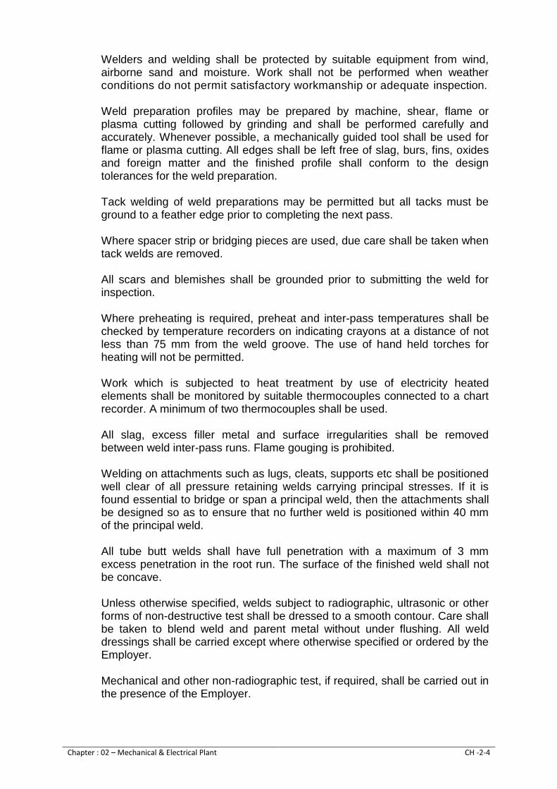
Chapter : 02 – Mechanical & Electrical Plant CH -2-4
Welders and welding shall be protected by suitable equipment from wind, airborne sand and moisture. Work shall not be performed when weather conditions do not permit satisfactory workmanship or adequate inspection.
Weld preparation profiles may be prepared by machine, shear, flame or plasma cutting followed by grinding and shall be performed carefully and accurately. Whenever possible, a mechanically guided tool shall be used for flame or plasma cutting. All edges shall be left free of slag, burs, fins, oxides and foreign matter and the finished profile shall conform to the design tolerances for the weld preparation.
Tack welding of weld preparations may be permitted but all tacks must be ground to a feather edge prior to completing the next pass.
Where spacer strip or bridging pieces are used, due care shall be taken when tack welds are removed.
All scars and blemishes shall be grounded prior to submitting the weld for inspection.
Where preheating is required, preheat and inter-pass temperatures shall be checked by temperature recorders on indicating crayons at a distance of not less than 75 mm from the weld groove. The use of hand held torches for heating will not be permitted.
Work which is subjected to heat treatment by use of electricity heated elements shall be monitored by suitable thermocouples connected to a chart recorder. A minimum of two thermocouples shall be used.
All slag, excess filler metal and surface irregularities shall be removed between weld inter-pass runs. Flame gouging is prohibited.
Welding on attachments such as lugs, cleats, supports etc shall be positioned well clear of all pressure retaining welds carrying principal stresses. If it is found essential to bridge or span a principal weld, then the attachments shall be designed so as to ensure that no further weld is positioned within 40 mm of the principal weld.
All tube butt welds shall have full penetration with a maximum of 3 mm excess penetration in the root run. The surface of the finished weld shall not be concave.
Unless otherwise specified, welds subject to radiographic, ultrasonic or other forms of non-destructive test shall be dressed to a smooth contour. Care shall be taken to blend weld and parent metal without under flushing. All weld dressings shall be carried except where otherwise specified or ordered by the Employer.
Mechanical and other non-radiographic test, if required, shall be carried out in the presence of the Employer.

Chapter : 02 – Mechanical & Electrical Plant CH -2-5
Welder shall be qualified in accordance with the requirements of the appropriate section of BS 4872 or BS 4871 whichever is applicable.
2.7. Castings
The structure of castings shall be homogeneous and free from non-metallic inclusions and other defects. Surfaces of casting which are not machined shall be carefully fettled to remove all foundry irregularities.
Minor defects not exceeding 10 mm in depth or 10% of total metal thickness whichever is less and which will not ultimately affect the strength and serviceability of the casting may be repaired by approved welding techniques.
If the removal of metal from repair reduces the stress-resisting cross-section of the casting by more than 25% or to such an extent that the computed stress in the remaining metal exceeds the allowable stress by more than 25% then the casting shall be rejected.
Castings repaired by welding for major defects shall be stress-relieved.
Non-destructive tests may be required for any casting containing defects whose effect can otherwise be established, or to determine that repair welds have been properly made.
Unless otherwise specified, casting shall be produced to the following standards or equal:
Grey-Iron BS 1452 Grade 220 Carbon Steel BS 3100 Steel alloy
Stainless Steel BS 3100 Steel 316 C16
Copper & Copper alloy BS 1400 Group A grade LG2 Group B grade CTI, AB2 GRAD C grade G 1
2.8. Forgings
Major stress-bearing forgings shall be made to a standard specification. They shall be subjected to internal examination and non-destructive tests for the detection of flaws and shall be heat-treated for the relief of residual stress.
2.9. Nuts, bolts, studs and washers
Nuts and bolts for pressure fittings as a minimum shall be of zinc plated high quality steel machined on the shank and under the head and the nut. Bolts shall be of such a length that only one to three-threads shall show through the nut when in the fully tightened condition.
Fitted bolts shall be a tight driving fit in the reamed holes they occupy, they shall have the screwed portion of such a diameter that it will not be damaged in driving and shall be marked in a conspicuous position to ensure correct assembly at site.
Chapter : 02 – Mechanical & Electrical Plant CH -2-6
Washers, locking devices and anti-vibration fittings shall be provided where necessary to ensure that no bending stress is caused in the bolt.
When there is a risk of corrosion, bolts and studs shall be designed so that the maximum stress in the bolt does not exceed half the yield stress of the material under all conditions. All bolts, nuts and screws which are subject to frequent adjustment or removal in the course of maintenance and repair shall be made of nickel-bearing stainless steel or brass.
The Contractor shall supply all holding down, aligning and leveling bolts complete with anchorages, nuts, washers and packing required to attach the plant to foundations.
Unless otherwise necessary to meet special requirement all threads shall be have preferred metric sizes with standard coarse thread.
ISO metric black hexagon bolts, nuts and screws shall comply with S11 0585-81, or ISO 885, ISO 888, ISO 898-1 and ISO 898-2 and BS 4190 strength Grade 4.6.
ISO metric precision hexagon bolts, nuts and screw shall comply with ISO 272. ISO 4759-1, ISO 885, ISO888 898-1 and 2 or ASTM F-593, ASTM F-468M, strength Grade 8.8 and BS 3692 strength Grade 8.8.
The dimensions of metric countersunk head bolts, screws and hexagon nuts shall comply with ISO 225 or ISO 888 or ISO 898-1.
Plain steel washer for use with ISO metric bolts shall comply with ISO 887 or ASTM F-884.
Taper steel washer shall comply with ASTM F-844 and ASTM F-436.
2.10. Non-metallic materials
Fabrics, cork, paper and similar materials which are not subsequently to be protected by impregnation shall be treated with an approved fungicide. Sleeves and fabrics treated with linseed oil varnish shall not be used.
The use of organic materials shall be avoided as far as possible, but where these have to be used, they shall be treated to make them fire resistant and non-flame propagating.
The use of wood shall be avoided as far as possible. If used, woodwork shall be seasoned teak or similar hardwood which is resistant to fugal decay and free from distortion and faults.
Woodwork shall be treated to protect it against damage by fire, moisture, fungus, vermin, insect, bacteria or chemical attack, unless it is naturally resistant to all these Joints in woodwork shall be dovetailed or tongued and pinned. Metal fitting on wood shall be of nonferrous material. Adhesives shall be impervious to moisture and fungus growth. Synthetic resin cement only

Chapter : 02 – Mechanical & Electrical Plant CH -2-7
shall be used for joining wood. The use of casein cement will not be permitted.
2.11. Guards for moving parts
All moving parts shall be protected by safety guards. Guards shall be rigid, securely fixed and designed to allow normal operation, running, maintenance and routine inspection to be carried out on equipment without the need to remove the guard. Where this is impractical, guards shall be designed for easy fixing, dismantling and re-assembly.
2.12. Safeguarding of Plant
The Contractor shall ensure that the whole of the Work as installed is safe for use by the operating and maintenance staff, and by any other persons having access thereto. Guards, electrical safety devices, thermal insulation, noise suppression devices, written notices, safety colours and the like shall be provided where necessary during erection and as a permanent feature.
Plant layout shall be designed to provide easy and safe access to valves hand wheels, electrical equipment, instruments and any other operating devices, free from hazardous obstructions.
Nothing in the Specification shall remove the Contractor’s obligation from drawing the attention of the Employer to any feature of the Work which is not consistent with safety or prevents him from making proposals for incorporating equipments of design which would increase the safety of the Plant.
2.13. Rating plates, name plates and labels
The Contractor shall supply a Plant identification system showing the name and number of each item of the Plant and its respective arrangement drawing number and add any additional items necessary to fully identify it.
The Contractor shall supply all labels, nameplates, instruction and warning plates necessary for the identification and safe operation of the Plant.
All such labeling shall be securely fixed to items of plant and equipment with stainless steel rivets, plated self-tapping screws or other approved means. The use of adhesives will not be permitted.
Nameplates for plant, and equipment identification and record purposes shall be manufactured from stainless steel with a matt or satin finish and engraved with black lettering of a size which is legible from the working position.
Warning plates/labels shall be manufactured from stainless steel engraved with white lettering on a red background and sited in the position where they afford maximum safety of personnel.

Chapter : 02 – Mechanical & Electrical Plant CH -2-8
All equipment within panels and desk shall be individually identified by satin or matt finish stainless steel labels or laminated plastic labels where approved.
Pipe work systems shall be color coded in accordance with the requirements of BS 1710.
Each valve shall be fitted with a stainless steel nameplate indicating the valve service and reference where nameplates shall be circular and fitted under the hand wheels captive nut. They have to be of such a diameter that there is no danger for persons operating the valve or that they do not prevent lock-off of the valve. For check valves and small valves, the Contractor may provide rectangular nameplates fitted to brackets on the valves or attached to a wall or steel work in convenient positions adjacent to the valves.
2.14. Lubrication: 2.14.1. General
Items of Plant shall be lubricated as necessary to ensure operation, heat removal and freedom from undue wear. Lubricated items shall be designed so that they do not require more than monthly lubrication attendance, unless otherwise required.
All grease nipples, oil cups and dip sticks shall be readily accessible, being piped where necessary to convenient positions.
The Contractor shall supply first fill of oil and grease for both Plant and maintenance equipment. In addition, the Contractor shall provide adequate supplies of lubricants for all equipment sufficient for 12 months of normal operation from the date of the Taking Over.
A complete schedule of recommended oils and other lubricants shall be provided by the Contractor as part of the Operating and Maintenance Manuals. The number of different types of lubricants shall be kept to a minimum. In the case of grease lubricated ball and roller bearing, a lithium based grease is preferred.
2.14.2. Oil lubrication
Oil reservoirs shall be fitted with oil-level indicators of the sight glass type, or where this is not practicable, with dipsticks. The normal, maximum and minimum levels shall be clearly visible to an operator standing on the normal access floor to the particular item of plant. The sight glasses stall be made from toughened glass, easily dismantled for cleaning and in exposed situations, fitted with the guards.
Drain points shall be located or piped to such a position that an adequately sized container can be placed beneath them.

Chapter : 02 – Mechanical & Electrical Plant CH -2-9
For forced oil lubrication systems, the pressure shall be monitored during operation with automatic shutdown of the machine and alarm on low oil pressure.
All oil lubricated machinery shall utilize a common grade of oil which is readily available in Pakistan. High temperature high performance lubricates shall be avoided as far as possible.
2.14.3. Grease Lubrication
Grease lubrication shall be for steel lubrication nipples manufactured in accordance with BS 1486.
A separate nipple shall be provided to secure each lubrication point. Where a number of nipples supply remote lubricating points, they shall be grouped together on a conveniently placed batter plate, with spacings in accordance with BS 1486.
The Contractor shall provide a grease gun for each size and type of nipple installed. Where different types of greases are involved, separate grease guns shall be provided for each type. They shall be suitably labeled and if possible of different style to prevent incorrect greasing.
2.15. Joint Rings & Gaskets
Joint rings shall be manufactured to conform to BS 2194 and shall be of chloroprene rubber or other approved synthetic material suitable for temperatures up to 80 oC or greater to suit the application.
Joints shall be made in accordance with manufacturer’s instructions or as specified herein. Until immediately required for incorporation in a joint, each rubber ring or gasket shall be stored in the dark, free from the deleterious effects of heat or cold and kept flat so as to prevent any part of the rubber being in tension.
Only lubricants recommended by the manufacturer shall be used in connection with rubber rings and these lubricants shall not contain any constituents soluble in water. They shall be suitable for the climatic conditions at site and shall contain an approved bactericide.
Graphite grease or similar shall be applied to the threads of bolts before joints are made.
2.16. Electroplating, galvanizing and sherardising
Parts to be galvanized, other than nuts, bolts and fasteners, shall be hot dip galvanized to BS 729 to give a minimum average coating of 610 g/m² area covered and a zinc thickness of not less than 85 microns.
Where specified, nuts, bolts and fasteners to be galvanized shall be hot dip galvanized to BS 729 to give a minimum average coating of 305 g/m² and a zinc thickness of not less than 43 microns. Where hot dip galvanizing is not

Chapter : 02 – Mechanical & Electrical Plant CH -2-10
practicable, nuts, bolts and fasteners shall be sherardised. Sherardising shall be in accordance with BS 4291, the thickness of zinc coating being not less than 30 microns.
Where chromium plating is used, it shall comply with the requirements of BS 1224 including the provision that no blistering of any surfaces will be accepted. For all base metals, the service condition number 2 shall be used.
2.17. Noise
The Plant shall be designed and constructed to reduce the operating noise level as much as possible. During periods of short duration or abnormal operation (e.g. during startup) higher noise level up to an additional 20 dB (A) may be acceptable at the discretion of the Employer.
Except as provided for below, the noise emitted by any single item of the Plant shall not exceed a sound pressure level of 85 dB (A) when measured at a distance of 1 m from the reference surface of that item in a horizontal direction and under the environmental conditions appropriate to the test requirements of ISO 3746 “Acoustic Determination of Sound Power Levels of Noise – Survey Methods” or the equipment ANSI S1 36.
The Contractor shall carry out noise tests on Site if in the opinion of the Employer, the Plant is excessively noisy. Sound pressure levels shall be measured in dB (A) using a calibrated sound meter meeting the requirements of BS 4197 with a response speed set to “Slow”. The background noise level shall be at least 10 dB (A) below the operating noise level of the machine or other item of the Plant.
For major items of the Plant, the Contractor shall provide workshop certificates from the manufacturer covering noise level tests carried out on the items or type test certificates for similar items of the Plant.
If any item of Plant in its standard built, does not comply with the above requirement, the Contractor shall be required to reduce the sound pressure level by providing improved or additional silencers or fitting sound insulating materials to the item, until the requirement is met.
Noise levels in control rooms and offices shall not exceed 45 dB (A) with equipment such as printers in operation and in local plant control rooms it shall not exceed 70 dB (A).
The background noise level at any point along the boundary of the Site, arising from operation of the Plant shall not exceed 65 dB (A).
2.18. Vibration
All rotating elements shall be dynamically balanced so that the level of vibration at any point on a machine when operating at Site, either singly or with other machines, and at any speed throughout the operating range shall be within the limits of Class IV, Grade B as defined in BS 4675 Part 1.

Chapter : 02 – Mechanical & Electrical Plant CH -2-11
“Machine” shall mean a complete assembly including its drive shafting, motor and bedplate, generator, and compressor etc.
Pipe work, valves and other equipment connected to the machine or forming part of the operating system, shall be with provided adequate supports, brackets and fixtures, as necessary to restrict any induced vibration to a minimum under any operating condition.
Vibration measurements shall be taken on Site by the Contractor at various points on each complete machine as defined above.
Measurements shall also be taken on connecting Plant. If any item is found to be vibrating beyond the level considered by the Employer to be reasonably minimum for the particular Item, the Contractor shall take further steps to bring vibration to the required level. Equipment with unacceptable vibration levels may be rejected if the Contractor is unable to achieve satisfactory operation of the equipment involved.
2.19. Corrosion and erosion
The Contractor shall make proper provision for the prevention of corrosion and erosion in any part of his Plant. Such provision shall include the use of suitable materials, choice of operating speeds, design of components and type of protective coating and finishes. Particular attention shall be given to the Plant that may be exposed to water from different sources with varying characteristics and possible galvanic reaction with dissimilar metals.
2.20. Precautions against dampness
Special precautions shall be taken to prevent corrosion due to humidity, rainfall and moisture. All wall-mounted equipment shall be fitted with spacers to provide a minimum gap of 5 mm. All holes in the equipment shall be effectively sealed against the ingress of water. All items exposed to weather or water shall be free of water traps. Where necessary drain holes shall be provided to prevent the accumulation of water.
All fixings, fastenings and spacers which may be submerged in a corrosive liquid shall be galvanized or sherardised, unless otherwise specified. All electrical equipment which is not sealed against free movement of air shall be protected from condensation with anti-condensation heaters. In general these heaters shall be thermostatically controlled and switched off when heat is generated by the operation of the Plant.
In choosing materials and their finishes due regard is to be given to the conditions under which the equipment is to Work. Tropical duty materials should be used throughout the Plant.

Chapter : 02 – Mechanical & Electrical Plant CH -2-12
Iron and steel are to be painted or galvanized in accordance with the Specification. Small iron and steel parts (other than stainless steel) of all instruments and electrical equipment, the cores of electromagnets and the metal parts of relays and mechanisms are to be treated in an approved manner to prevent rusting, Cores etc which are built up of laminations or cannot for any other reason be antirust treated are to have all exposed parts cleaned and heavily enameled or lacquered.
When it is necessary to use dissimilar metals in contact these should be so selected so that the electrochemical potential difference is not greater than 250 milli-volts and if practicable the two metals are to be insulated from each other by an approved insulating material or by a coating of approved varnished compound.
The use of iron and steel is to be avoided in instruments and electrical relays wherever possible. Steel screws when used are to be zinc, cadmium or chromium plated or when plating is not possible owing to tolerance limitations, are to be of corrosion resisting steel. Springs are to be of brass, bronze or non-rusting material. Pivots for which non-ferrous material is unsuitable are to be of approved rustless steel where possible.
The use of wood within electrical and mechanical equipment is to be avoided as far as possible and, if used shall be of a type resistant to termite attack and fungal decay.
The use of hygroscopic insulating materials is not permitted except immersed in oil or otherwise suitably sealed to prevent ingress of moisture. In choosing materials and their finishes due regard is to be given to the conditions under which the equipment is to Work. Typical duty materials should be used throughout the Plant.
Springs are to be of brass, bronze or non-rusting material. Pivots for which non-ferrous material is unsuitable are to be of approved rustles steel where possible.
2.21. Protective finishes
The surfaces of Plant shall be fully protected against corrosion and erosion with the exception of steel or similar corrosion resistant material or where the surface is required to be clear for operational purpose, e.g at glands, bearing, etc.
Parts to be galvanized shall be designed to avoid overlapping surfaces and narrow gaps and pockets which may trap pickling acid. Thermal distortion or the creation of unacceptable residual stresses should not occur. Nuts, bolts and fasteners shall be of stainless steel Grade 316 S312 or shall have corrosion, resistant finish. Galvanizing, sherardising, or electroplating of fasteners shall be to BS 3353. Cadmium plating shall not be used.

Chapter : 02 – Mechanical & Electrical Plant CH -2-13
The paint protection system shall be obtained from the same manufacturer and applied strictly in accordance with the manufacturer's instructions and requirements and in accordance with BS 5493 and 6160. The Contractor shall be responsible for cleaning surfaces and preparing them for protective treatment and protective coatings applied at the place of manufacture and at Site. Coatings shall not be applied to external surfaces at Site during rain, fog, mist or condensation or when wind borne dirt and dust are present or likely to be present before the coating is dry enough to be undamaged.
All items of plant shall be delivered to Site with their protective finish fully applied. Site painting shall be limited to the making good of damaged protective finish and the application of further decorative coats to provide a clean and uniform finish to the whole of the Work. Site painting shall not be carried out unless the surface to be painted is dry and has undergone surface preparation as instructed by the paint manufacturer. In general Site painting shall be applied only when ambient temperatures are above 16 degrees and relative humidity is less than 55%. If these conditions cannot be achieved, a special painting system may be applied with the approval of the Employer.
Mating surfaces shall have primary coats applied before assembly. The mating surfaces of structural steel shall be sealed during erection.
Care shall be taken not to paint over any nameplates, rating plates, labels etc. All bearing and gland surfaces shall be protected during final painting.
All coatings used for any part of the Plant in contact with water for potable use shall be non-toxic, non-carcinogenic, not impart taste, odor, color or turbidity to the water. Only materials included in the approved list of the UK water fittings and by-laws scheme (operated by WRc) or in the “Current Statement of the Committee” on chemicals and materials of the construction for use in public water supply and swimming pools (issued by DOE) shall be used in places where they may come into contact with water to be used for potable purposes.
The protective treatment system shall enable any necessary repairs, whether during the Contract period or subsequently to be made simply, without need for special skills or equipment. “Two pack” product shall not be used on any of the Plant Item.
The following table gives the minimal acceptable finish system for different types of plant. Further detailed requirements for specific items of plant if given in the Specification shall take precedence over any requirement stated here:

Chapter : 02 – Mechanical & Electrical Plant CH -2-14
Hand-railing, walkways and steel structure installed inside and outside buildings.
Hot dip galvanized/stainless steel where specifically mentioned.
Steel pipe work 100 mm dia. and larger. Fusion bounded epoxy.
Steel pipe work under 100 mm dia. and smaller.
Hot dip galvanized.
Ductile iron pipe work. Bitumen coating.
Steel surfaces other than pipe work in damp or wet environment.
Zinc rich epoxy or zinc spray followed by epoxy top coat.
Electrical switchgear in dry uncontrolled atmosphere.
Stove dried enamel or manufacturer’s standard finish.
Electrical switchgear in damp uncontrolled atmosphere.
Stainless steel or GRP enclosure self-colored.
Table 2-1: Minimal Acceptable Finish System
Paint finished shall include color coding taping (BS 1710) of pipes for chemicals, treated and raw water to the approval of the Employer.
2.22. Water Compliance of Materials in Contact with Water
Any materials that come or may come in contact with water which is to become potable shall comply with one of the following.
a) The UK Secretary of State for the Environment under Section 25 of the
water supply (Water Quality Regulation 1989). b) The 15th Statement of the UK Department of Environment Committee
on Chemical and Materials for use in public water supply. c) The American Food and Drug Association. d) Other internationally recognized and approved body. Where a material does not comply with the above it shall be subject to the approval of Employer. Certificates confirming compliance with the above shall be submitted to the Employer and these shall form part of the approval/acceptance of the Plant.

EMPLOYERS REQUIRMENT FOR
MECHANICAL & ELECTRICAL WORKS
CHAPTER 03
GENERAL TESTING, INSPECTION, COMMISIONING AND TRAINING REQUIRMENTS

CHAPTER 03
GENERAL TESTING, INSPECTION, COMMISIONING AND TRAINING REQUIRMENTS
TABLE OF CONTENTS
3.1. Work Testing - General ........................................................................................................... 1
3.2. Test instruments ..................................................................................................................... 1
3.3. Test certificates ....................................................................................................................... 2
3.4. Hydraulic Works Tests ............................................................................................................. 2
3.5. Works Inspection, test and guarantee .................................................................................... 2
3.6. Pumps and pump sets ............................................................................................................. 3
3.7. Valves ...................................................................................................................................... 3
3.8. Cranes and lifting equipment .................................................................................................. 4
3.9. Motors ..................................................................................................................................... 4
3.10. Low and medium voltage switching devices........................................................................... 4
3.11. Switchboards and motor control centers ............................................................................... 5
3.12. Cables ...................................................................................................................................... 7
3.13. Process, control and indicating instruments .......................................................................... 7
3.14. Electrical measuring instruments and meters ........................................................................ 7
3.15. Alarm system .......................................................................................................................... 7
3.16. Site testing .............................................................................................................................. 7
3.16.1. Co-ordination of Site testing program ................................................................................ 7 3.16.2. Cable test during installation ............................................................................................... 8
3.17. Tests before completion ......................................................................................................... 8
3.18. Tests on completion ................................................................................................................ 9
3.18.1. Pump sets ............................................................................................................................. 10 3.18.2. Cranes and lifting equipment............................................................................................. 10 3.18.3. Ancillary equipment ............................................................................................................ 10 3.18.4. Pipework .............................................................................................................................. 10 3.18.5. Valves ................................................................................................................................... 11 3.18.6. Surge protection system..................................................................................................... 11 3.18.7. Screens ................................................................................................................................. 12 3.18.8. Electrical plant and power systems ................................................................................... 12 3.18.9. Switchgear and Motor Control Centers ............................................................................ 12 3.18.10. Instruments and metering equipment .............................................................................. 13 3.18.11. Continuity of earth conductors ......................................................................................... 13 3.18.12. Rotating machines (motors) ............................................................................................... 13 3.18.13. Earthing systems ................................................................................................................. 13 3.18.14. Electrical equipment and installations ............................................................................. 14 3.18.15. Building and site services ................................................................................................... 14 3.18.16. Transformers ....................................................................................................................... 14
3.19. Training of Employees O & M staff ....................................................................................... 15
3.19.1. General ................................................................................................................................. 15 3.19.2. Familiarization Programs .................................................................................................... 15 3.19.3. Practical training ................................................................................................................. 15
3.20. 12 Months On-the-Job training............................................................................................. 16

3.21. Taking over ............................................................................................................................ 16
3.22. Defect Liability Period ........................................................................................................... 16

Chapter : 03 - GENERAL TESTING, INSPECTION, COMMISIONING & TRAINING REQUIRMENTS
CH-3-1
CHAPTER 03
MATERIAL & WORKMAN SHIP GENRAL TESTING, INSPECTION, COMMISIONING
AND TRAINING REQUIREMENTS 3.1. Work Testing - General
The Contractor shall offer all items of Plant for inspection examination and witness testing by the Employer. In such cases the Contractor shall give the Employer four weeks’ notice that the equipment is ready for tests.
The Contractor shall carry out tests as stated in the current appropriate British Standards, performance tests and such other tests as specified or as necessary.
Where witness tests are not required the test certificate and performance curves shall be forwarded to the Employer. On each test certificate and performance curves sufficient information shall be given for ready identification of the material or equipment to which the certificate refers. Inspection or passing by the Employer of the Work, Plant or materials covered by the Contract, whether carried out or supplied by the Contractor shall not release the Contractor from any of his obligations under the Contract.
The Employer reserves the right to require the Contractor to meet any extra costs which are occasioned by failure of the Contractor to comply with the above testing and inspection requirements including the provision of test certificates, curves, sub-orders, etc. or which in the opinion of the Employer are due to insufficient care having been taken by the Contractor before presenting the Plant for inspection or test. If unauthorized delivery has taken place, the Contractor may be required to arrange for the Plant to be returned to the manufacturer for inspection and/or witness testing or even replacement at the Contractor’s expense.
Any equipment used in the testing of the Plant shall in all respects comply with the appropriate safety regulations and/or requirements regarding electrical apparatus for the safety of the Plant and the men working thereon.
The Contract price shall include the costs of all works, tests, including temporary erection, labour, materials, instrumentation, stores, fuel and power used, as may be required during all inspections and tests and for the provision of certified records and curves.
3.2. Test instruments
The manufacturer shall ensure the accuracy of all the instruments used for the tests and if required shall produce recent calibration tests, or otherwise have them calibrated at his own expense by an independent authority.

Chapter : 03 - GENERAL TESTING, INSPECTION, COMMISIONING & TRAINING REQUIRMENTS
CH-3-2
Kilowatt hour meter shall be checked for correct calibration and creep tests shall be carried out to ensure that the meter is in-operative with voltage alone if the secondary current transformer is left connected with the primary current interrupted.
3.3. Test certificates
Test certificates shall be provided giving a detailed record of all electrical and mechanical tests carried out on the equipment and material including lifting equipment, pumps, motors, valves, cables and cabling etc. both in the manufacturer’s works and at site.
Copies of certificates of all works, hydraulics tests shall be provided.
The Contractor shall submit to the Employer within two weeks of completion of any witness tests, test certificates and curves of all items certifying that they have been satisfactorily tested.
Copies of test certificates of major items shall be included in the Operating and Maintenance Manuals.
3.4. Hydraulic Works Tests
All equipment subject to water pressure including pumps, pipes, fittings and valves shall be hydraulically tested to the pressure where specified or to at least 1.5 times the maximum working pressure or to 1.5 times the closed valve pressure, whichever is the highest.
3.5. Works Inspection, test and guarantee
All the schedules shall be completed with the guaranteed particulars and efficiencies of the equipment offered at the duties specified and these will be binding and may not be varied.
Witness testing to the relevant standards and to prove guarantees given may be required for the following items:
Pumps
Valves
Screening equipment
Electric motors
Control / switchgear panels
Cranes and lifting equipment
Control, measuring, indicating, instruments and alarms
Electrical measuring instruments and meters
Alarm systems
The Employer may at his discretion require witness testing of items not included in the above list.

Chapter : 03 - GENERAL TESTING, INSPECTION, COMMISIONING & TRAINING REQUIRMENTS
CH-3-3
Where items of equipment are of identical size and duty, it may be required at the discretion of the Employer that a reduced number of items be subjected to witness tests. However, this shall not relieve the Contractor from the requirement of carrying out performance tests on all items.
If after inspection, examination or testing, the Employer decides that any material or equipment is not in accordance with the Specification or performance requirement, he shall reject the said item and the Contractor shall replace and retest the item at his own cost.
As and when the Employer is satisfied that the equipment has passed the required tests he shall notify the Contractor in writing to that effect.
3.6. Pumps and pump sets
One pump of each type shall be tested in accordance with Part 2 of BS 5316. Site conditions shall be fully simulated, including the minimum site Net Positive Suction Head (NPSH) condition and site suction pipework configuration.
Pump shall be tested with the tested and certified Contract motor including intermediate shafting, as required.
Pump shall be tested at the guaranteed duty point and over its full working range from closed valve condition to 10% in excess of the minimum head. Duty head / quantity curves, power / quantity and overall efficiency/quantity and NPSHr/quantity curves shall be plotted to demonstrate that the Plant will be capable of meeting the operating conditions at Site. Efficiency of the pump and the overall pumpsets wire efficiency shall be established on test.
Pump shall be dismantled after test and inspection carried out to confirm the satisfactory condition of all parts prior to dispatch to Site.
The results of the above tests on pumps, motors and drives will be used by the Employer to determine whether each pumpset has achieved the performance guarantees. If a pumpset fails to achieve the guaranteed performance, the Contractor shall carry out such further works as he considers necessary and shall arrange for tests to be repeated. This procedure shall be continued until the pumpset performs as guaranteed or the pump is rejected.
3.7. Valves
All valve bodies shall be hydraulically tested closed ended to 1.5 times the rated pressure. All isolating valve seats shall be tested to the maximum working pressure, at which pressure they shall be drop tight. Each valve shall be tested for functional operation with its own actuator.

Chapter : 03 - GENERAL TESTING, INSPECTION, COMMISIONING & TRAINING REQUIRMENTS
CH-3-4
3.8. Cranes and lifting equipment
The cranes and lifting equipment shall be assembled and tested in the manufacturer’s works to 25 percent above the rated load and test certificates provided.
Full functional tests of all crane motions shall be demonstrated with the crane carrying the maximum working load. All mechanical and electrical equipment shall be shown to operate smoothly within rated capacity. A deflection test in accordance with BS 4666 shall be carried out.
3.9. Motors
Electric motors shall be individually tested off-Site to IEC 60034 & BS 4999: Part 143, at work test ambient temperature at the machine frame power output–rating after application of de-rating factors for Site temperatures, duty factor and Site power supplies. Verification of guaranteed efficiencies and power factor shall be carried out using the de-rated power output application on Site, which shall be nameplate rating. Motors of 5.5 kW rating and over shall each be subjected to full ‘Basic’ tests, and in addition to noise level tests to BS 4999 Part 109, except that where two or more identical motors are being provided under the Contract. One motor shall be subjected to full ‘Basic’ tests and the remainder subjected to ‘Duplicate’ tests. Motor under 5.5 kW rating shall each be subjected to ‘Duplicate’ tests providing that a Type Test Certificate for full ‘Basic’ test and noise level test to BS 4999: Part 109 of a similar motor is available. Where no such Type Test Certificate is available, testing shall be as follows for motors with rating of 5.5 kW and over.
Type test certificate shall include the following minimum information and shall be provided for all motors: a. Manufacture standard b. Class of insulation c. Type of cable fittings d. Type of bearings, sizes and lubricants e. Type and rating of heaters f. Brush sizes and maker (if fitted)
3.10. Low and medium voltage switching devices
Low and medium voltage switching devices shall be subjected to Routine Tests in accordance with the following standards: a. Low voltage devices
(1) Low voltage circuit breakers shall be tested in accordance with IEC
60947 Part 2.
(2) Miniature circuit breakers shall be tested in accordance with IEC 60898

Chapter : 03 - GENERAL TESTING, INSPECTION, COMMISIONING & TRAINING REQUIRMENTS
CH-3-5
(3) Low voltage air-break switches and fuse-combination units shall be
tested in accordance with IEC 60947 Part 3.
(4) Low voltage contactors shall be tested in accordance with IEC 60947 Part 1.
b. Medium voltage devices
(1) Medium voltage circuit breakers shall be tested in accordance with IEC
62271 Part 4. Medium Voltage switches shall be tested in accordance with IEC 60265
(2) Medium voltage contactors shall be tested in accordance with BS 775,
Part 2.
(3) Medium voltage direct-on-line starters shall be tested in accordance with lEC-60632 – 1.
(4) All medium Voltage switching devices of current rating 100 A or greater
shall be subject to measurement, at the main terminals of each pole with the contacts fully closed of dc voltage and current (at 100A or greater).
The values of resistance for any two similar examples from a particular manufacturer range shall not differ by more than 2%.
3.11. Switchboards and motor control centers
Factory built assemblies of low voltage switchgear and control gear shall be subject to Routine Tests in accordance with IEC 60439.
Medium voltage metal enclosed switchgear and control gear shall be subject to Routine Tests in accordance with IEC 62271
Additionally low voltage and medium voltage switchgear and control gear assemblies shall be tested for the following:
a. Measurements of main circuit resistance The resistance of each pole of each main circuit from the cable terminal to bushes with all intervening switch contacts fully closed shall be measured and recorded. A similar measurement and record shall be taken along the length of each bus-bar with bus-section switch contacts fully closed. The tests shall comprise of the measurement of dc voltage and current (at 100A or greater) and calculation of resistance.

Chapter : 03 - GENERAL TESTING, INSPECTION, COMMISIONING & TRAINING REQUIRMENTS
CH-3-6
b. Interchangeability All components of the same rating and construction, designated as draw-out or plug-in shall be demonstrated as being interchangeable. c. Protection and control circuits For all forms of current transformer protection, the following information shall be made available to the Employer before the time of Inspection:
(1) Current transformer magnetizing curve (2) Recommended relay setting (3) Calculated primary operating current at this setting (4) Calculated through-fault stability values where applicable (5) Values of any stabilizing and setting resistors employed in the system
As far as possible, the satisfactory operation of associated control and protection circuits shall be proved by the following tests: (1) To ensure the correct operation of all current operated protection relays
and direct acting coils at the recommended setting by primary current injection.
(2) To ensure the correct polarity between current and voltage elements of power relays, meters and instruments.
(3) To ensure the correct operation of dc operated auxiliary protection relays,
such as Buchholz protection relays at normal operating voltage by simulated operation of associated remote relays.
(4) To ensure the correct operation of control circuits at normal operating
voltage by operation of local control switches and simulation of operation from remote control positions.
Note: Checking the operation of all protection relays and control circuits shall be carried out with all closing and tripping circuits energized at their normal rated voltage. d. Instrument and metering equipment Indicating Ammeter shall be checked for calibration at 0.25, 0.5 and full scale deflection by primary current injection testing. Indicating voltmeters shall be checked for normal voltage readings by secondary voltage application. Where possible, integrating kWh meters shall be tested for correct operation. Tests shall be carried out to ensure that the meter is in-operative with voltage alone, with the secondaries of current transformers connected and the primary current interrupted.
Chapter : 03 - GENERAL TESTING, INSPECTION, COMMISIONING & TRAINING REQUIRMENTS
CH-3-7
All instruments shall be subject to the manufacturers normal work tests. 3.12. Cables
All cables shall be subject to routine tests in accordance with the relevant Standard Specification.
Test certificates shall be provided against each drum and / or cable length.
The tests carried out on every cable length and / or drum at manufacturer’s premises shall include:
a. High voltage dc insulation pressure rest, between cores, each core to earth, metallic sheath or armor as applicable.
b. Insulation resistance test.
c. Core continuity and identification
d. Conductor resistance test 3.13. Process, control and indicating instruments
All flow, level and process measurement controllers, transmitters, recorder, indicators, vacuum and pressure gauges shall be subject to routine tests in accordance with BS 88, BS 1780 and BS3680.
Test certificates shall be provided against each item of equipment.
3.14. Electrical measuring instruments and meters
Tests to ensure accurate operation of all meters, Voltmeters and kiloWatt hour meters shall be undertaken in accordance with BS 89 and BS 37.
3.15. Alarm system
The Contractor shall test all items of equipment comprising the alarm system for correct operation and sequence action.
3.16. Site testing
3.16.1. Co-ordination of Site testing program
The Contractor shall be responsible for coordinating the program of Site testing of all items and to ensure that all parties concerned are present during any tests to obligate their responsibilities.

Chapter : 03 - GENERAL TESTING, INSPECTION, COMMISIONING & TRAINING REQUIRMENTS
CH-3-8
3.16.2. Cable test during installation
During the period of Site installation, the Employer will carry out inspection of the works to ensure that the standard of workmanship meets the Specification. In the event of any part of the cabling installation failing to meet the requirements, the Contractor shall remedy the deficiency to the satisfaction of the Employer. The Contractor shall: a. Inform the Employer prior to the testing of the cables and shall be
responsible to liaising with any other party to whose equipment the cables may be terminated to ensure that all parties concerned are aware of the impending tests, to guarantee the safety of personnel and that the isolation of any equipment has been completed. Any special isolation or preparation required to be carried out before cable testing will be carried out by the party responsible for equipment. All tests shall be carried out by the Contractor but shall be supervised by the Employer.
b. Provide high voltage dc test equipment and conduct the high voltage dc test (with necessary isolations and safeguards) at specified voltage in accordance with relevant standards between cores, cores and sheath & cores and armor as applicable on power cables installed on power systems.
c. Demonstrate correct phasing out of cores in all cables throughout the
works and test the insulation of all cables, both between the cores and between the cores and earth, during installation with a “Megger” 500 Volt hand generator.
d. Conduct soil resistivity tests in the presence of the Employer to obtain the
most suitable location for the earth electrode system.
e. Demonstrate to the Employer that the resistance of the earth electrodes to earth conductor continuity and earth installation is in accordance with the specified requirements.
Tests shall be performed for each major item of plant, by using an “Earth Megger” and auxiliary return conductor.
If any portion of the work fails to pass the tests, another test of the failed portion shall be repeated within a reasonable time.
3.17. Tests before completion
Tests before completion shall be undertaken by the Contractor in line with the following general requirements.
In general these tests may be undertaken without supervision or witnessing by the Employer but the Employer shall be kept informed of the program of these

Chapter : 03 - GENERAL TESTING, INSPECTION, COMMISIONING & TRAINING REQUIRMENTS
CH-3-9
tests and given the opportunity to supervise and witness the tests where he considers this appropriate.
Tests before Completion shall as a minimum comprise of: a. Pressure test to check tightness of joints, coupling etc.
b. Continuity test on power and control cabling including armouring
c. Visual inspection and tests for insulation resistance, earth loop impedance,
polarity and phase rotation. The test shall be carried out between phases and phase to earth. All circuit breakers, switches and contactors shall be in their circuit position and closed. All secondary small wiring circuits shall be similarly tested.
d. Satisfactory operation of all current operated protection circuits over their
whole operating range shall be checked by primary current injection. Where primary injection tests have been previously performed at the manufacturer’s premises, secondary current injection testing may be used subject to approval by the Employer.
e. Correct operation of control circuits, indications and alarms shall be
demonstrated.
f. Correct operation of current and voltage operated indicating instruments and meters.
g. Electrical pressure test on high voltage equipment.
h. Earth continuity and resistivity test.
i. Off–load operation / function test of all mechanical plant and electrical
switchgear.
j. Rotational check on all motor drives.
k. All remedial work required is satisfactorily completed.
3.18. Tests on completion
After erection is completed and the equipment is running satisfactorily after preliminary setting to work the Contractor shall notify the Employer that he is ready to demonstrate the performance of the Plant. Such demonstration referred to herein as Tests on Completion, shall be witnessed by the Employer. The Contractor shall then test fully all items of equipment and shall include provision and arrangement of:-
All skilled and qualified operating and test staff for the testing of all equipment.
Provision and disposal of all services, lubricants and electricity.

Chapter : 03 - GENERAL TESTING, INSPECTION, COMMISIONING & TRAINING REQUIRMENTS
CH-3-10
All measuring and testing instruments to demonstrate that the equipment operated to the fulfillment of the work tests.
All tests shall be carried out by the Contractor under the supervision of and to the satisfaction of the Employer as follows:
3.18.1. Pump sets Tests in accordance with Part-1 of BS 5316 to demonstrate that each pump set is reliable in operation and is able to cover the whole working range. Each pump shall be tested at the minimum guaranteed and maximum duty points. The values obtained will be compared with the values obtained during the tests on the manufacturer’s premises and any discrepancies shall be rectified by the Contractor. Pump in combination with other duty pumps shall be similarly tested.
Temporary facilities, including flow measurement, instrumentation and throttling valves shall be provided at the pumping installation for recycling the test flow from any single pump back to the suction conduit if possible. This may be through permanent pumping station by pass pipework, if provided.
Pumps in combination of 2, 3 or 4 pumps shall be tested after being installed to ensure smooth, vibration free suction and delivery and the manifold and to certify delivery by each pump singularly and in combination of full and guaranteed delivery requirements.
3.18.2. Cranes and lifting equipment
The Crane inclusive of rails and beams shall be tested at site with test loads provided by the Contractor to prove that the whole is capable of satisfactorily lifting 25 percent above its rated load (lift in centre of gantry).
Cranes shall be tested after erection. A vertical deflection test shall be carried out with the "safe working load" suspended from the hook with the crab in the centre of the span. Workshop functional tests shall be repeated.
A further condition assessment and functional check shall be carried out prior to taking over. Any deterioration resulting from the Contractor's use of the crane during Plant erection shall be rectified by the Contractor.
3.18.3. Ancillary equipment
The Contractor shall demonstrate the satisfactory operation of the Plant and associated control equipment.
3.18.4. Pipework
Following completion of installation, all station pipework shall be water tested for leakage at appropriate test pressures. In the case of delivery pipework,

Chapter : 03 - GENERAL TESTING, INSPECTION, COMMISIONING & TRAINING REQUIRMENTS
CH-3-11
and such other pipework on the suction side as may be vulnerable to full delivery pressure, the test pressure shall be the same as the Site test pressure for the associated delivery pipeline. All pipework erected at Site shall be hydraulically tested, following erection, to at least 1.5 times the maximum working pressure, The Contractor shall provide the necessary equipment including any temporary blank flanges, which may be required to isolate the equipment.
The Contractor shall be responsible for testing of the welds and inspecting and testing of welded joints together with the responsibility of making good of any welding defect. Faulty welds shall be rectified in accordance with the requirements of BS 2971.
The Contractor shall provide all the necessary facilities, labour and equipment for the proper execution of the inspections and bend testing included in BS 2971. Two sets of bend tests shall be allowed for by the Contractor.
Fittings required for temporarily closing the openings in the pipelines to be tested shall be properly designed for the purpose and shall be adequately strutted to withstand the pressure applied.
Where bursting disks are installed, one disk shall be tested to demonstrate satisfactory operation.
3.18.5. Valves All valves on completion of erection shall be fully functionally tested in association with their actuators, controls and bypass system where provided. Each installation shall be checked for water tightness and the valves for any leakage. Valves shall be subject to the system test pressure and shall be demonstrated to function satisfactorily under maximum site differential head conditions. Where appropriate, valves may be internally inspected after functional tests to verify that seals remain in a satisfactory condition.
3.18.6. Surge protection system
The Contractor is required to survey and check the data supplied with the detailed plan and profile of steel pumping main to enable him to compute and meet the requirements of surge protection system in different case studies with adequate safety margin. The Contractor shall ensure that protective devices are provided for all possible cases of origin of surge in the system and its damaging effects and adequate safety devices are provided in the installation to avoid damage to the Plant and pipe line system.
Following completion of pumping installations and associated delivery pipelines, the Contractor shall demonstrate, to the satisfaction of the Employer that the surge protection systems installed including surge bypass systems or surge vessels are sufficient to provide the degree of protection required.
Chapter : 03 - GENERAL TESTING, INSPECTION, COMMISIONING & TRAINING REQUIRMENTS
CH-3-12
Transient pressures shall be monitored and recorded at various points along the pipeline during the tests to verify the surge predictions and the adequacy of the surge protection equipment.
Any equipment supplied under the Contract that requires readjustment during the above tests shall after readjustment again be demonstrated by the Contractor to the satisfaction of the Employer. Third Party validation of surge Analysis will be got carried out by the Contractor. Profile of the Third Party shall be submitted for review by the Employer.
3.18.7. Screens All screens on completion of erection shall be fully functionally tested to meet the performance schedule and specifications. Tests on all electrical items and control gear shall be carried out as specified under electrical plant and power systems.
3.18.8. Electrical plant and power systems
For electrical plant and power systems the tests on Completion shall comprise pre-commissioning test “as detailed below, prior to energisation from the power supply source followed by energisation and demonstration of the operation of the Plant and associated protection and control systems to the specified performance requirements and maximum operating and load duties.
All tests shall be carried out by the Contractor under the supervision of and to the approval of the Employer.
3.18.9. Switchgear and Motor Control Centers i. Insulation testing
Power, frequency and pressure tests shall be carried out on all equipment for operation on MV system.
For LV systems equipment insulation tests shall be carried out at 500 volt using an approved test instrument.
These tests shall be carried out with all circuit breaker- contactor panels closed in the circuit position, between phases and phase to earth. All secondary small wiring circuits shall be similarly tested.
ii. Mechanical tests All mechanical tests specified for conducting on manufacturer’s premises are to be rechecked to ensure satisfactory operation in the final erected state.
iii. Protection and control circuits The satisfactory operation of all current operated protection circuits over their whole operating range shall be tested by secondary current injection,
Chapter : 03 - GENERAL TESTING, INSPECTION, COMMISIONING & TRAINING REQUIRMENTS
CH-3-13
where primary injection tests have been previously carried out on manufacturer’s premises.
Primary injection tests shall be carried out on restricted earth fault circuits after pilot circuits have been completed for stability and fault conditions. On transformer differential protection circuits where primary injection was not possible at the place of manufacture, the completed relay circuits are to be fully tested by secondary injection with simulated fault conditions. Stability tests are to be carried out using normal load conditions after the system has been completed and energized.
3.18.10. Instruments and metering equipment
Tests shall be carried out to ensure the correct operation of current and voltage operated indication instruments when energized by the actual supply system.
3.18.11. Continuity of earth conductors
Continuity tests shall be carried out on the earth conductor within the switchboard, such tests being done by current injection.
3.18.12. Rotating machines (motors)
Before the application of electric power on the machine windings, the insulation resistance shall be tested with a suitable insulation resistance tester, which shall be greater than the manufacturer’s minimum recommended figure when corrected for Site winding temperature. Any necessary drying out of the windings on Site shall be in accordance with the manufacturer’s recommendations.
Before rotating any machine under power, the mechanical alignment of the drive shaft with the driven load shall be checked (and adjusted if necessary) and shall be in accordance with the manufacturer’s recommendation.
Before mechanically coupling any machine to the driven load, the direction of rotation shall be checked.
Before running any machine on-load, all heavy current connections shall be checked for correctness of make-up and tightness.
3.18.13. Earthing systems
The Contractor shall test that the resistance of the earthing network and electrodes are within the specified limits and in compliance with the Supply Authority’s Regulations.

Chapter : 03 - GENERAL TESTING, INSPECTION, COMMISIONING & TRAINING REQUIRMENTS
CH-3-14
3.18.14. Electrical equipment and installations
The Contractor will in addition be responsible for arranging and carrying out such witnessed or un-witnessed tests and inspections as may be required by the Electric Supply Authority and obtain and hand over to the Employer their certificate of approval of the complete electrical installation.
3.18.15. Building and site services
The Contractor shall demonstrate that the building services and installations conform to the Specification and applicable local regulations.
The tests shall include but not limited to: a. For lighting installations to demonstrate that the illumination levels conform
to the specified values.
b. For ventilation and air-conditioning installations to conduct all operational tests for all plants.
The measurement of air ventilation and air volumes at test points shall demonstrate:
a. The specified performance duties of all installed fans.
b. The correct balancing of air duct systems, if applicable.
c. The satisfactory regulation of all air grills and diffusers to achieve the specified air flow rates at all points in the system.
d. The measurement and recording of noise levels to demonstrate
compliance with the Specification. 3.18.16. Transformers
Routine and type tests shall be carried out on transformers to IEC 60076, IEC 60137, IEC 60296 & IEC 60060 or equivalent. Routine tests shall include:
i. Insulation resistance ii. Ratio, polarity and phase relationship iii. Measurements of winding resistance on all tap positions and phase iv. Impedance voltage v. Over voltage withstand vi. Load loss vii. Noise level

Chapter : 03 - GENERAL TESTING, INSPECTION, COMMISIONING & TRAINING REQUIRMENTS
CH-3-15
3.19. Training of Employees O & M staff 3.19.1. General
The Contractor shall impart training to the Employees staff on all aspects of plant operation for a period of 12 months. This will be in house on-the-job training after completion of testing and commissioning works. The Contractor shall submit his staffing proposal to the Employer which will be for three shift operation per day and for the day maintenance staff. The staffing schedule shall be forwarded to the Employer 12 months before the commencement of commissioning and Reliability Trials period to enable the Employer to appoint /depute the required staff.
The staff will remain under the supervision and control of the Contractor for evaluating their capabilities and performance. The Contractor shall ensure that the staff is fully conversant with all aspects of plant operations and are capable to take over the plant after completion of their training.
3.19.2. Familiarization Programs
These programs shall be theoretical as well as practical. Theoretical programs shall cover all aspects of plant operation and maintenance through lectures and audio/video devices. As a minimum these shall comprise of: (1) Day to day operation and maintenance procedures
(2) Proper procedures for carrying out repair and replacement works
(3) Trouble shooting
(4) Material procurement and storage
(5) Maintenance and janitorial services of the Plant
(6) Security
(7) Actions required under emergencies viz fire, earthquake and rains etc.
(8) Job description of all positions.
(9) Printed hand-outs in Urdu / English for each position holder for carrying
out responsibilities described therein.
3.19.3. Practical training This shall comprise of: (1) Visits to similar installations in Karachi
(2) Visits to selected manufacturing works in Karachi

Chapter : 03 - GENERAL TESTING, INSPECTION, COMMISIONING & TRAINING REQUIRMENTS
CH-3-16
3.20. 12 Months On-the-Job training
This will be an in house Training on the Contract Works as and when completed and commissioned. The Contractor shall continue plant operations and shall provide all services, staff and materials at his cost. After completion of this training the Employees staff should be fully conversant with the operation and maintenance of the Contract Work and capable to take over the operation and maintenance responsibilities independently.
3.21. Taking over After satisfactory completion of all mechanical, electrical and civil works as per Contract provisions and on completion of twelve months training period, the Work shall be taken over by the Employer as per provisions of Civil Works of the Contract.
3.22. Defect Liability Period
After issue of taking over certificate by the Employer, the Defect Liability Period of minimum 12 months shall commence. The Contractor’s responsibility at no additional cost in the Contract shall include but not limited to:
a. Providing skilled maintenance staff in each discipline for the whole period b. Monitoring performance of the Work c. Investigation fault in similar equipment under similar conditions d. Rectifying fault at his cost

EMPLOYER’S REQUIRMENT FOR MECHANICAL & ELECTRICAL WORKS
CHAPTER 04 MATERIALS & WORKMANSHIP
MECHANICAL WORKS

CHAPTER 4
MATERIALS & WORKMANSHIP MECHANICAL WORKS
TABLE OF CONTENTS
4.1. Introduction ................................................................................................................... 1 4.2. Reference of Standards ................................................................................................. 1 4.3. Abbreviations for references of standard ...................................................................... 1 4.4. Plant design and life ...................................................................................................... 2 4.5. Workmanship ................................................................................................................ 3 4.6. Welding ......................................................................................................................... 3 4.7. Castings ......................................................................................................................... 5 4.8. Forgings ........................................................................................................................ 5 4.9. Nuts, bolts, studs and washers ...................................................................................... 5 4.10. Non-metallic materials .................................................................................................. 6 4.11. Guards for moving parts ............................................................................................... 7 4.12. Safeguarding of Plant .................................................................................................... 7 4.13. Rating plates, name plates and labels ........................................................................... 7 4.14. Lubrication .................................................................................................................... 8
4.14.1. General......................................................................................................................... 8 4.14.2. Oil lubrication .............................................................................................................. 8 4.14.3. Grease Lubrication ....................................................................................................... 9
4.15. Joint rings & Gaskets .................................................................................................... 9 4.16. Electroplating, galvanizing and sherardising ................................................................ 9 4.17. Noise ........................................................................................................................... 10 4.18. Vibration ..................................................................................................................... 10 4.19. Corrosion and erosion ................................................................................................. 11 4.20. Precautions against dampness ..................................................................................... 11 4.21. Protective finishes ....................................................................................................... 12 4.22. Water Compliance of Materials .................................................................................. 14 4.23. High lift pump sets ...................................................................................................... 14 4.24. Pump performance guarantees .................................................................................... 15 4.25. Dry pit installation ...................................................................................................... 16 4.26. Submersible pumps ..................................................................................................... 18 4.27. Pipe work and fittings ................................................................................................. 19 4.28. Steel Specials .............................................................................................................. 21 4.29. Pipe Fabrication and Installation ................................................................................ 21 4.30. Valves & Penstocks .................................................................................................... 22
4.30.1. General....................................................................................................................... 22 4.30.2. Material ...................................................................................................................... 23
4.31. Gasket ......................................................................................................................... 24 4.32. Valve operating equipment and headstocks ................................................................ 24 4.33. Electrically operated actuators .................................................................................... 25
4.33.1. Type A electric actuators ........................................................................................... 26 4.33.2. Type B Electric Actuators .......................................................................................... 26
4.34. Penstocks .................................................................................................................... 27 4.35. Types of Valves .......................................................................................................... 27
4.35.1. Gate Valves ................................................................................................................ 27 4.35.2. Ball Valves ................................................................................................................ 28 4.35.3. Check Valves ............................................................................................................. 29 4.35.4. Butterfly valves .......................................................................................................... 30

4.35.5. Flow control valves .................................................................................................... 31 4.35.6. Ball float valve ........................................................................................................... 31 4.35.7. Pressure relief valves ................................................................................................. 31 4.35.8. Automatic air relief valves ......................................................................................... 32 4.35.9. Diaphragm valves ...................................................................................................... 32
4.36. Electric overhead traveling crane ................................................................................ 32 4.37. Access steelwork ......................................................................................................... 34 4.38. Pressure Gauges .......................................................................................................... 35 4.39. Sump Model Test ........................................................................................................ 35 4.40. Manual Coarse Screen ................................................................................................ 37 4.41. Chain hauled raking bar screens ................................................................................. 37 4.42. Central flow band screens ........................................................................................... 39

Chapter : 04 – Mechanical Works CH 4-1
CHAPTER 04 MECHANICAL WORKS
4.1. Introduction
This Chapter of the Specification sets out the minimum standards of materials, workmanship and design to be used by the Contractor for mechanical works. Reference to any specific material or equipment does not necessarily imply that such material or equipment is included in the Work.
All components/parts of the Work shall, unless otherwise specified, comply with the provisions of this Chapter unless overridden by the Employer’s Requirements or be subject to the approval of the Employer.
4.2. Reference of Standards
All goods, materials and workmanship shall comply with the requirements of the latest issue (with up to date amendments) of the appropriate standard or standards of the British Standards Institution or, if none is applicable, with the standards of best practice.
Where standards other than British Standards are proposed by the Contractor in his tender, the acceptance of the tender based on such standards shall only signify the approval to the use of such standards, but shall not make the Employer liable to accept any standard subsequently found inferior to the corresponding British Standard. The Employer shall be empowered to reject any material components and workmanship found to be inferior to the appropriate British Standard and the Contractor shall make good the deficiency at his own expense.
The Contractor may propose at no extra cost to the Employer the use of any alternative relevantly authoritative and internationally recognized reference of standard which shall be no less exacting than the corresponding standard quoted in the Specification. The Contractor shall demonstrate to the Employer that the alternative standard is suitable and equivalent to the specified standard as well as provide proof of previous successful use.
4.3. Abbreviations for references of standard
The following abbreviations where used in the specification refer to standard; codes of practice and other publications published by the organizations listed below: ACI : American Concrete Institute ANSI : American National Standard Institute API : American Petroleum Institute ASA : American Standard Association ASCE : American Society of Civil Engineers

Chapter : 04 – Mechanical Works CH 4-2
ASME : American Society of Mechanical Engineers ASTM : American Society of Testing and Materials AWS : American Welding Society AWWA : American Water Works Association BS : British Standard Institute CP : British Standard Institution (Code of Practice) DIN : German Industrial Standard HMSO : Her Majesty’s Stationary Office IEE : The Institute of Electrical Engineers IEC : International Electro-technical Commission I Mech E : The Institute of Mechanical Engineers ISO : International Organization for Standardization JIS : Japanese Industrial Standard NEMA : National Electrical Manufacturers Association SI : International System of Units SIS : Swedish Standard Commission
4.4. Plant design and life
The plant as a whole shall be new, of sound workmanship, robustly designed for a long reliable operating life and shall be capable of 24 hours per day continuous operation for prolonged periods and with minimum maintenance required. Particular attention shall be given to temperature changes, the stability of paint finish for high temperatures, the rating, electrical machinery, thermal overload services, cooling systems and the choice of lubricants for possible high and prolonged operation at high ambient temperature.
The plant shall be designed to provide easy and safe access and replacement of component parts which are subject to wear, without the need to replace whole units except for consumable items. No part subject to wear shall have a life of less than five years from new to replacement or repair. Where major dismantling is unavoidable to replace a part, the life of such part shall not be less than ten years.
Component parts shall be designed to be manufactured to strict limits of accuracy and to be interchangeable with parts of similar plant.
Design features shall include the protection of Plant against damage caused by vermin, dirt, dust and dampness and to reduce risk of fire. Plant shall operate without undue vibration and parts shall be designed to withstand the maximum stresses under the most severe conditions of normal service. Materials shall have a high resistance to change in their properties due to the passage of time, exposure to light, temperature and any other cause which may have a detrimental effect upon the performance or life of the Work. All materials in contact with water shall be impervious to it and not impart taste, odor and toxicity or otherwise be harmful to health or adversely affect the quality of water conveyed.
Manually operated plant located outside a building or structure shall be vandal-proof in addition to any other requirement in the Specification in respect of security.

Chapter : 04 – Mechanical Works CH 4-3
Outdoor equipment shall be weatherproof and designed to exclude dust and to prevent the collection of water at any point. Metal-to-metal joints will not be permitted and all external bolts or screw shall be provided with blind tapped holes where a through hole would permit the ingress of moisture.
Mechanisms shall be constructed of materials which will not corrode due to rust, corrosion, brine or dust. Bearings of exposed operating shafts shall be designed to prevent moisture seeping along the shaft into the interior of the equipment.
Equipment and instruments shall not be located in positions where they are vulnerable to falling objects or water drips. Weather shields shall be provided where necessary to protect equipment and instruments from the sun.
4.5. Workmanship
Workmanship and the general finish of Plant installations shall be of first class commercial quality and in accordance with the best workshop practice and shall be performed by persons skilled in their respective trades.
Pipe work, fittings, cables, cable trays, etc, shall be fitted in a neat, straight and symmetrical manner so as to present a pleasing appearance.
Indicating gauges fitted to machine assemblies or to control panels shall generally be of similar style and grouped in a neat manner.
External welds and flame cuts shall have a smooth finish by means of careful grinding. Floor plate covering shall be fixed squarely in their frames and with their patterns lined-up. Hand railings shall be free from burrs.
4.6. Welding
All welding electrodes, wire and fluxes shall be stored in a clean dry place and protected from all forms of deterioration. All welding consumables shall be properly identified and shall retain their identification up to the time of use. Each batch of electrodes and wire shall be identifiable with the respective manufacturer’s test certificate and advice note and shall be used in strict delivery rotation.
Gas cylinders shall be supplied to the site marked in accordance with the requirements of ISO 8448. They shall be stored under a suitable sunshade.
All welding equipment shall be of sufficient capacity and be maintained in such a condition as to ensure welds of acceptable quality throughout the range of electrode sizes to be used on the work.
Welding machine earth or ground leads shall be firmly fixed to the workplace. Welding cables shall be maintained in good condition and shall be free from kinks and loose connections.

Chapter : 04 – Mechanical Works CH 4-4
Welders and welding shall be protected by suitable equipment from wind, airborne sand and moisture. Work shall not be performed when weather conditions do not permit satisfactory workmanship or adequate inspection.
Weld preparation profiles may be prepared by machine, shear, flame or plasma cutting followed by grinding and shall be performed carefully and accurately. Whenever possible, a mechanically guided tool shall be used for flame or plasma cutting. All edges shall be left free of slag, burs, fins, oxides and foreign matter and the finished profile shall conform to the design tolerances for the weld preparation.
Tack welding of weld preparations may be permitted but all tacks must be ground to a feather edge prior to completing the next pass.
Where spacer strip or bridging pieces are used, due care shall be taken when tack welds are removed.
All scars and blemishes shall be grounded prior to submitting the weld for inspection.
Where preheating is required, preheat and inter-pass temperatures shall be checked by temperature recorders on indicating crayons at a distance of not less than 75 mm from the weld groove. The use of hand held torches for heating will not be permitted.
Work which is subjected to heat treatment by use of electricity heated elements shall be monitored by suitable thermocouples connected to a chart recorder. A minimum of two thermocouples shall be used.
All slag, excess filler metal and surface irregularities shall be removed between weld inter-pass runs. Flame gouging is prohibited.
Welding on attachments such as lugs, cleats, supports etc shall be positioned well clear of all pressure retaining welds carrying principal stresses. If it is found essential to bridge or span a principal weld, then the attachments shall be designed so as to ensure that no further weld is positioned within 40 mm of the principal weld.
All tube butt welds shall have full penetration with a maximum of 3 mm excess penetration in the root run. The surface of the finished weld shall not be concave.
Unless otherwise specified, welds subject to radiographic, ultrasonic or other forms of non-destructive test shall be dressed to a smooth contour. Care shall be taken to blend weld and parent metal without under flushing. All weld dressings shall be carried except where otherwise specified or ordered by the Employer.
Mechanical and other non-radiographic test, if required, shall be carried out in the presence of the Employer.

Chapter : 04 – Mechanical Works CH 4-5
Welder shall be qualified in accordance with the requirements of the appropriate section of BS 4872 or BS 4871 whichever is applicable.
4.7. Castings
The structure of castings shall be homogeneous and free from non-metallic inclusions and other defects. Surfaces of casting which are not machined shall be carefully fettled to remove all foundry irregularities.
Minor defects not exceeding 10 mm in depth or 10% of total metal thickness whichever is less and which will not ultimately affect the strength and serviceability of the casting may be repaired by approved welding techniques.
If the removal of metal from repair reduces the stress-resisting cross-section of the casting by more than 25% or to such an extent that the computed stress in the remaining metal exceeds the allowable stress by more than 25% then the casting shall be rejected.
Castings repaired by welding for major defects shall be stress-relieved.
Non-destructive tests may be required for any casting containing defects whose effect can otherwise be established, or to determine that repair welds have been properly made.
Unless otherwise specified, casting shall be produced to the following standards or equal:
Grey-Iron BS 1452 Grade 220 Carbon Steel BS 3100 Steel alloy
Stainless Steel BS 3100 Steel 316 C16
Copper & Copper alloy BS 1400 Group A grade LG2 Group B grade CTI, AB2 GRAD C grade G 1
4.8. Forgings
Major stress-bearing forgings shall be made to a standard specification. They shall be subjected to internal examination and non-destructive tests for the detection of flaws and shall be heat-treated for the relief of residual stress.
4.9. Nuts, bolts, studs and washers
Nuts and bolts for pressure fittings as a minimum shall be of zinc plated high quality steel machined on the shank and under the head and the nut. Bolts shall be of such a length that only one to three-threads shall show through the nut when in the fully tightened condition.
Fitted bolts shall be a tight driving fit in the reamed holes they occupy, they shall have the screwed portion of such a diameter that it will not be damaged in driving and shall be marked in a conspicuous position to ensure correct assembly at site.

Chapter : 04 – Mechanical Works CH 4-6
Washers, locking devices and anti-vibration fittings shall be provided where necessary to ensure that no bending stress is caused in the bolt.
When there is a risk of corrosion, bolts and studs shall be designed so that the maximum stress in the bolt does not exceed half the yield stress of the material under all conditions. All bolts, nuts and screws which are subject to frequent adjustment or removal in the course of maintenance and repair shall be made of nickel-bearing stainless steel or brass.
The Contractor shall supply all holding down, aligning and leveling bolts complete with anchorages, nuts, washers and packing required to attach the plant to foundations.
Unless otherwise necessary to meet special requirement all threads shall be have preferred metric sizes with standard coarse thread.
ISO metric black hexagon bolts, nuts and screws shall comply with S11 0585-81, or ISO 885, ISO 888, ISO 898-1 and ISO 898-2 and BS 4190 strength Grade 4.6.
ISO metric precision hexagon bolts, nuts and screw shall comply with ISO 272. ISO 4759-1, ISO 885, ISO888 898-1 and 2 or ASTM F-593, ASTM F-468M, strength Grade 8.8 and BS 3692 strength Grade 8.8.
The dimensions of metric countersunk head bolts, screws and hexagon nuts shall comply with ISO 225 or ISO 888 or ISO 898-1.
Plain steel washer for use with ISO metric bolts shall comply with ISO 887 or ASTM F-884.
Taper steel washer shall comply with ASTM F-844 and ASTM F-436.
4.10. Non-metallic materials
Fabrics, cork, paper and similar materials which are not subsequently to be protected by impregnation shall be treated with an approved fungicide. Sleeves and fabrics treated with linseed oil varnish shall not be used.
The use of organic materials shall be avoided as far as possible, but where these have to be used, they shall be treated to make them fire resistant and non-flame propagating.
The use of wood shall be avoided as far as possible. If used, woodwork shall be seasoned teak or similar hardwood which is resistant to fugal decay and free from distortion and faults.
Woodwork shall be treated to protect it against damage by fire, moisture, fungus, vermin, insect, bacteria or chemical attack, unless it is naturally resistant to all these Joints in woodwork shall be dovetailed or tongued and pinned. Metal fitting on wood shall be of nonferrous material. Adhesives shall be impervious to moisture and fungus growth. Synthetic resin cement only

Chapter : 04 – Mechanical Works CH 4-7
shall be used for joining wood. The use of casein cement will not be permitted.
4.11. Guards for moving parts
All moving parts shall be protected by safety guards. Guards shall be rigid, securely fixed and designed to allow normal operation, running, maintenance and routine inspection to be carried out on equipment without the need to remove the guard. Where this is impractical, guards shall be designed for easy fixing, dismantling and re-assembly.
4.12. Safeguarding of Plant
The Contractor shall ensure that the whole of the Work as installed is safe for use by the operating and maintenance staff, and by any other persons having access thereto. Guards, electrical safety devices, thermal insulation, noise suppression devices, written notices, safety colours and the like shall be provided where necessary during erection and as a permanent feature.
Plant layout shall be designed to provide easy and safe access to valves hand wheels, electrical equipment, instruments and any other operating devices, free from hazardous obstructions.
Nothing in the Specification shall remove the Contractor’s obligation from drawing the attention of the Employer to any feature of the Work which is not consistent with safety or prevents him from making proposals for incorporating equipments of design which would increase the safety of the Plant.
4.13. Rating plates, name plates and labels
The Contractor shall supply a Plant identification system showing the name and number of each item of the Plant and its respective arrangement drawing number and add any additional items necessary to fully identify it.
The Contractor shall supply all labels, nameplates, instruction and warning plates necessary for the identification and safe operation of the Plant.
All such labeling shall be securely fixed to items of plant and equipment with stainless steel rivets, plated self-tapping screws or other approved means. The use of adhesives will not be permitted.
Nameplates for plant, and equipment identification and record purposes shall be manufactured from stainless steel with a matt or satin finish and engraved with black lettering of a size which is legible from the working position.
Warning plates/labels shall be manufactured from stainless steel engraved with white lettering on a red background and sited in the position where they afford maximum safety of personnel.

Chapter : 04 – Mechanical Works CH 4-8
All equipment within panels and desk shall be individually identified by satin or matt finish stainless steel labels or laminated plastic labels where approved.
Pipe work systems shall be color coded in accordance with the requirements of BS 1710.
Each valve shall be fitted with a stainless steel nameplate indicating the valve service and reference where nameplates shall be circular and fitted under the hand wheels captive nut. They have to be of such a diameter that there is no danger for persons operating the valve or that they do not prevent lock-off of the valve. For check valves and small valves, the Contractor may provide rectangular nameplates fitted to brackets on the valves or attached to a wall or steel work in convenient positions adjacent to the valves.
4.14. Lubrication
4.14.1. General
Items of Plant shall be lubricated as necessary to ensure operation, heat removal and freedom from undue wear. Lubricated items shall be designed so that they do not require more than monthly lubrication attendance, unless otherwise required.
All grease nipples, oil cups and dip sticks shall be readily accessible, being piped where necessary to convenient positions.
The Contractor shall supply first fill of oil and grease for both Plant and maintenance equipment. In addition, the Contractor shall provide adequate supplies of lubricants for all equipment sufficient for 12 months of normal operation from the date of the Taking Over.
A complete schedule of recommended oils and other lubricants shall be provided by the Contractor as part of the Operating and Maintenance Manuals. The number of different types of lubricants shall be kept to a minimum. In the case of grease lubricated ball and roller bearing, a lithium based grease is preferred.
4.14.2. Oil lubrication
Oil reservoirs shall be fitted with oil-level indicators of the sight glass type, or where this is not practicable, with dipsticks. The normal, maximum and minimum levels shall be clearly visible to an operator standing on the normal access floor to the particular item of plant. The sight glasses stall be made from toughened glass, easily dismantled for cleaning and in exposed situations, fitted with the guards.
Drain points shall be located or piped to such a position that an adequately sized container can be placed beneath them.
Chapter : 04 – Mechanical Works CH 4-9
For forced oil lubrication systems, the pressure shall be monitored during operation with automatic shutdown of the machine and alarm on low oil pressure.
All oil lubricated machinery shall utilize a common grade of oil which is readily available in Pakistan. High temperature high performance lubricates shall be avoided as far as possible. 4.14.3. Grease Lubrication
Grease lubrication shall be for steel lubrication nipples manufactured in accordance with BS 1486.
A separate nipple shall be provided to secure each lubrication point. Where a number of nipples supply remote lubricating points, they shall be grouped together on a conveniently placed batter plate, with spacings in accordance with BS 1486.
The Contractor shall provide a grease gun for each size and type of nipple installed. Where different types of greases are involved, separate grease guns shall be provided for each type. They shall be suitably labeled and if possible of different style to prevent incorrect greasing.
4.15. Joint rings & Gaskets
Joint rings shall be manufactured to conform with BS 2194 and shall be of chloroprene rubber or other approved synthetic material suitable for temperatures up to 80 oC or greater to suit the application.
Joints shall be made in accordance with manufacturer’s instructions or as specified herein. Until immediately required for incorporation in a joint, each rubber ring or gasket shall be stored in the dark, free from the deleterious effects of heat or cold and kept flat so as to prevent any part of the rubber being in tension.
Only lubricants recommended by the manufacturer shall be used in connection with rubber rings and these lubricants shall not contain any constituents soluble in water. They shall be suitable for the climatic conditions at site and shall contain an approved bactericide.
Graphite grease or similar shall be applied to the threads of bolts before joints are made.
4.16. Electroplating, galvanizing and sherardising
Parts to be galvanized, other than nuts, bolts and fasteners, shall be hot dip galvanized to BS 729 to give a minimum average coating of 610 g/m² area covered and a zinc thickness of not less than 85 microns.
Where specified, nuts, bolts and fasteners to be galvanized shall be hot dip galvanized to BS 729 to give a minimum average coating of 305 g/m² and a zinc thickness of not less than 43 microns. Where hot dip galvanizing is not

Chapter : 04 – Mechanical Works CH 4-10
practicable, nuts, bolts and fasteners shall be sherardised. Sherardising shall be in accordance with BS 4291, the thickness of zinc coating being not less than 30 microns.
Where chromium plating is used, it shall comply with the requirements of BS 1224 including the provision that no blistering of any surfaces will be accepted. For all base metals, the service condition number 2 shall be used.
4.17. Noise
The Plant shall be designed and constructed to reduce the operating noise level as much as possible. During periods of short duration or abnormal operation (e.g. during startup) higher noise level up to an additional 20 dB (A) may be acceptable at the discretion of the Employer.
Except as provided for below, the noise emitted by any single item of the Plant shall not exceed a sound pressure level of 85 dB (A) when measured at a distance of 1 m from the reference surface of that item in a horizontal direction and under the environmental conditions appropriate to the test requirements of ISO 3746 “Acoustic Determination of Sound Power Levels of Noise – Survey Methods” or the equipment ANSI S1 36.
The Contractor shall carry out noise tests on Site if in the opinion of the Employer, the Plant is excessively noisy. Sound pressure levels shall be measured in dB (A) using a calibrated sound meter meeting the requirements of BS 4197 with a response speed set to “Slow”. The background noise level shall be at least 10 dB (A) below the operating noise level of the machine or other item of the Plant.
For major items of the Plant, the Contractor shall provide workshop certificates from the manufacturer covering noise level tests carried out on the items or type test certificates for similar items of the Plant.
If any item of Plant in its standard built, does not comply with the above requirement, the Contractor shall be required to reduce the sound pressure level by providing improved or additional silencers or fitting sound insulating materials to the item, until the requirement is met.
Noise levels in control rooms and offices shall not exceed 45 dB (A) with equipment such as printers in operation and in local plant control rooms it shall not exceed 70 dB (A).
The background noise level at any point along the boundary of the Site, arising from operation of the Plant shall not exceed 65 dB (A).
4.18. Vibration
All rotating elements shall be dynamically balanced so that the level of vibration at any point on a machine when operating at Site, either singly or with other machines, and at any speed throughout the operating range shall be within the limits of Class IV, Grade B as defined in BS 4675 Part 1.

Chapter : 04 – Mechanical Works CH 4-11
“Machine” shall mean a complete assembly including its drive shafting, motor and bedplate, generator, and compressor etc.
Pipe work, valves and other equipment connected to the machine or forming part of the operating system, shall be with provided adequate supports, brackets and fixtures, as necessary to restrict any induced vibration to a minimum under any operating condition.
Vibration measurements shall be taken on Site by the Contractor at various points on each complete machine as defined above.
Measurements shall also be taken on connecting Plant. If any item is found to be vibrating beyond the level considered by the Employer to be reasonably minimum for the particular Item, the Contractor shall take further steps to bring vibration to the required level. Equipment with unacceptable vibration levels may be rejected if the Contractor is unable to achieve satisfactory operation of the equipment involved.
4.19. Corrosion and erosion
The Contractor shall make proper provision for the prevention of corrosion and erosion in any part of his Plant. Such provision shall include the use of suitable materials, choice of operating speeds, design of components and type of protective coating and finishes. Particular attention shall be given to the Plant that may be exposed to water from different sources with varying characteristics and possible galvanic reaction with dissimilar metals.
4.20. Precautions against dampness
Special precautions shall be taken to prevent corrosion due to humidity, rainfall and moisture. All wall-mounted equipment shall be fitted with spacers to provide a minimum gap of 5 mm. All holes in the equipment shall be effectively sealed against the ingress of water. All items exposed to weather or water shall be free of water traps. Where necessary drain holes shall be provided to prevent the accumulation of water.
All fixings, fastenings and spacers which may be submerged in a corrosive liquid shall be galvanized or sherardised, unless otherwise specified. All electrical equipment which is not sealed against free movement of air shall be protected from condensation with anti-condensation heaters. In general these heaters shall be thermostatically controlled and switched off when heat is generated by the operation of the Plant.
In choosing materials and their finishes due regard is to be given to the conditions under which the equipment is to Work. Tropical duty materials should be used throughout the Plant.

Chapter : 04 – Mechanical Works CH 4-12
Iron and steel are to be painted or galvanized in accordance with the Specification. Small iron and steel parts (other than stainless steel) of all instruments and electrical equipment, the cores of electromagnets and the metal parts of relays and mechanisms are to be treated in an approved manner to prevent rusting, Cores etc which are built up of laminations or cannot for any other reason be antirust treated are to have all exposed parts cleaned and heavily enameled or lacquered.
When it is necessary to use dissimilar metals in contact these should be so selected so that the electrochemical potential difference is not greater than 250 milli-volts and if practicable the two metals are to be insulated from each other by an approved insulating material or by a coating of approved varnished compound.
The use of iron and steel is to be avoided in instruments and electrical relays wherever possible. Steel screws when used are to be zinc, cadmium or chromium plated or when plating is not possible owing to tolerance limitations, are to be of corrosion resisting steel. Springs are to be of brass, bronze or non-rusting material. Pivots for which non-ferrous material is unsuitable are to be of approved rustless steel where possible.
The use of wood within electrical and mechanical equipment is to be avoided as far as possible and, if used shall be of a type resistant to termite attack and fungal decay.
The use of hygroscopic insulating materials is not permitted except immersed in oil or otherwise suitably sealed to prevent ingress of moisture. In choosing materials and their finishes due regard is to be given to the conditions under which the equipment is to Work. Typical duty materials should be used throughout the Plant.
Springs are to be of brass, bronze or non-rusting material. Pivots for which non-ferrous material is unsuitable are to be of approved rustles steel where possible.
4.21. Protective finishes
The surfaces of Plant shall be fully protected against corrosion and erosion with the exception of steel or similar corrosion resistant material or where the surface is required to be clear for operational purpose, e.g at glands, bearing, etc.
Parts to be galvanized shall be designed to avoid overlapping surfaces and narrow gaps and pockets which may trap pickling acid. Thermal distortion or the creation of unacceptable residual stresses should not occur. Nuts, bolts and fasteners shall be of stainless steel Grade 316 S312 or shall have corrosion, resistant finish. Galvanizing, sherardising, or electroplating of fasteners shall be to BS 3353. Cadmium plating shall not be used.

Chapter : 04 – Mechanical Works CH 4-13
The paint protection system shall be obtained from the same manufacturer and applied strictly in accordance with the manufacturer's instructions and requirements and in accordance with BS 5493 and 6160. The Contractor shall be responsible for cleaning surfaces and preparing them for protective treatment and protective coatings applied at the place of manufacture and at Site. Coatings shall not be applied to external surfaces at Site during rain, fog, mist or condensation or when wind borne dirt and dust are present or likely to be present before the coating is dry enough to be undamaged.
All items of plant shall be delivered to Site with their protective finish fully applied. Site painting shall be limited to the making good of damaged protective finish and the application of further decorative coats to provide a clean and uniform finish to the whole of the Work. Site painting shall not be carried out unless the surface to be painted is dry and has undergone surface preparation as instructed by the paint manufacturer. In general Site painting shall be applied only when ambient temperatures are above 16 degrees and relative humidity is less than 55%. If these conditions cannot be achieved, a special painting system may be applied with the approval of the Employer.
Mating surfaces shall have primary coats applied before assembly. The mating surfaces of structural steel shall be sealed during erection.
Care shall be taken not to paint over any nameplates, rating plates, labels etc. All bearing and gland surfaces shall be protected during final painting.
All coatings used for any part of the Plant in contact with water for potable use shall be non-toxic, non-carcinogenic, not impart taste, odor, color or turbidity to the water. Only materials included in the approved list of the UK water fittings and by-laws scheme (operated by WRc) or in the “Current Statement of the Committee” on chemicals and materials of the construction for use in public water supply and swimming pools (issued by DOE) shall be used in places where they may come into contact with water to be used for potable purposes.
The protective treatment system shall enable any necessary repairs, whether during the Contract period or subsequently to be made simply, without need for special skills or equipment. “Two pack” product shall not be used on any of the Plant Item.
The following table gives the minimal acceptable finish system for different types of plant. Further detailed requirements for specific items of plant if given in the Specification shall take precedence over any requirement stated here:

Chapter : 04 – Mechanical Works CH 4-14
Hand-railing, walkways and steel structure installed inside and outside buildings.
Hot dip galvanized/stainless steel where specifically mentioned.
Steel pipe work 100 mm dia. and larger. Fusion bounded epoxy.
Steel pipe work under 100 mm dia. and smaller. Hot dip galvanized.
Ductile iron pipe work. Bitumen coating.
Steel surfaces other than pipe work in damp or wet environment.
Zinc rich epoxy or zinc spray followed by epoxy top coat.
Electrical switchgear in dry uncontrolled atmosphere.
Stove dried enamel or manufacturer’s standard finish.
Electrical switchgear in damp uncontrolled atmosphere.
Stainless steel or GRP enclosure self coloured.
Nuts, bolts, washers and other small hardware. Stainless steel.
Table 4-1: Minimal Acceptable Finish System
Paint finished shall include color coding taping (BS 1710) of pipes for chemicals, treated and raw water to the approval of the Employer.
4.22. Water Compliance of Materials
Any materials that come or may come in contact with water which is to become potable shall comply with one of the following.
a) The UK Secretary of State for the Environment under Section 25 of the
water supply (Water Quality Regulation 1989). b) The 15th Statement of the UK Department of Environment Committee
on Chemical and Materials for use in public water supply. c) The American Food and Drug Association. d) Other internationally recognized and approved body. Where a material does not comply with the above it shall be subject to the approval of Employer. Certificates confirming compliance with the above shall be submitted to the Employer and these shall form part of the approval/acceptance of the Plant.
4.23. High lift pump sets
The Contractor shall provide for all the required components of the pumping Plant at Site in accordance with the Specification and Conceptual Drawings.
In selecting suitable pump sets for the stated performance, the Contractor shall ensure that as many components and items as possible are identical. Complete interchangeability of spares and other parts between all pumps is desirable.
All pumps shall be suitable for continuous operation at the performance specified and their duty levels shall be in the stable region of the pump characteristic curves. When required to do so, the pump shall operate satisfactorily in parallel with other pumps which may either be two or three or four in number.

Chapter : 04 – Mechanical Works CH 4-15
Pumps shall be of vertical shaft type meant for dry / wet pit installation as required, coupled with vertical shaft motors at ground floor level. They shall be quiet in operation and free from vibration. All rotating parts shall be dynamically balanced to BS 5265 and shall be so designed and constructed as to be capable of running unattended for long periods.
The component parts of the pumps shall be constructed from carefully selected materials designed to avoid all metallic corrosion resulting from the interaction of water with dissimilar and incompatible metals.
Fully detailed catalogues of the manufacturer and pump performance curves shall be submitted with the Tender. These shall cover the full operating range of all pumps whether operating alone or in parallel. Curves shall be plotted for flow, head, input power, and overall pump efficiency.
The Contractor shall submit a schedule of technical particulars on a prescribed Performa with the guaranteed performance with his Tender. The guarantees of performance shall be achieved by the Plant under the condition of works tests and Site tests and shall be considered binding and not be departed from without the written consent of the Employer. The pumps shall be fitted with renewable wear rings or sleeves in areas of close tolerance and where there is a high degree of wear.
Mechanical seals of cartridge or gland packing where specified, shall be used which shall be rated for continuous service without adjustments.
Pumps shall be capable of passing weed/algae present in lake water and shall be designed to avoid possible choking by weeds or other tough sinuous materials.
Unless otherwise specified, all bearings shall have a design running life of not less than 50,000 hours. Bearings shall be designed for loading 20% in excess of calculated maximum loading and shall be suitable for reverse rotation at 150% rated speed or the maximum reverse speed the pump can reach in installed conditions when driven backwards by reverse flow, if this is greater.
The rotating assemblies shall be statically and dynamically balanced to BS 5265 and designed so that the first critical speed of the pump and its drive is at least 50% higher than the normal operating speed.
4.24. Pump performance guarantees
Pump performance guarantees shall relate to the flow rate, the total head when tested at the manufacturer’s works. Verification of factory test results shall form part of the Site test on completion.
The pump shall operate at its duty point within the acceptance tolerances for flow and total head laid down in Clause 9.4.1 of BS 5316: Part 2 (ISO 3555),1997.
Chapter : 04 – Mechanical Works CH 4-16
Each pump shall be tested at manufacturer’s factory in accordance with BS 5316: Part 2 (ISO 3555) or other relevant standards in conjunction with one of the Contract motors.
Notwithstanding the requirements of BS 5316, the Contractor shall guarantee the pumps to operate safely, without cavitations, undue vibration or wear over the complete range of duties in which the pumps will operate.
The tests shall be carried out on at least one pump set using the Contract drive shaft arrangement to establish that the drive arrangement with supports and couplings operates satisfactorily under all operating conditions.
Where similar drive shaft arrangements have been installed by the Contractor and have proven satisfactory in service, this requirement may be withdrawn subject to the approval of the Employer.
The tests shall be carried - out of the performance from closed valve to the maximum quantity that can be delivered under abnormally low discharge heads when only one pump is operating. Sufficient readings shall be taken at each test to produce accurate curves of the head, flow, pump speed and power required at pump coupling throughout the operating range of the pump.
Vibration and noise dB (A) levels shall be measured and shown to be acceptable. The contractor shall provide acceptable test certificates, showing that the NPSH requirements for the pump are sufficiently less than the NPSH available under all working conditions.
4.25. Dry pit installation
Pump casings shall be of the volute type, made of best quality close grained cast iron and shall be capable of withstanding all pressure surges that may arise during operation.
All pump castings shall be manufactured and pressure tested in accordance with the latest issue of BS 1452. Material grade BS 1452 – 400 or GGG – 42 DIN 1693.
Casings shall be split to permit their removal to inspect or withdraw the rotating parts without dismantling pipe work. Equally spaced tapped holes shall be provided in one of each pair of joint flanges to facilitate their separation when dismantling and dowels or guide pillars shall be provided to ensure correct alignment on reassembly.
The pump casings shall not be integral with the base plate, but shall be designed to permit the removal of either the complete pump or internal components without affecting the mounting of the base plate.
Easily replaceable wear ring shall be provided between impeller and casing parts.

Chapter : 04 – Mechanical Works CH 4-17
Impellers shall be manufactured from best quality stainless steel. They shall be smooth, well finished, free from blow holes and imperfections, and shall be dynamically balanced.
Impellers shall be securely attached to their pump spindles in such a manner that they do not loosen or become detached when the pump is in operation, or when rotated in the opposite direction by reversed motor connections or by reverse flow.
Pump spindles or line shaftings shall be of stainless steel, machined, ground and fitted with renewable sleeves at the bearings and stuffing boxes. The shaft design shall be adequate without use of intermediate bearings, if possible.
All bearings shall be mounted in sealed dustproof housing and arranged for ease of lubrication. The complete rotor and spindle assembly shall be designed such that the running speed is well below the critical speeds and shall not exceed the specified speeds without the written approval of the Employer.
The pump casings shall be sealed against leakage along the shaft by stuffing boxes having pre – lubricated soft packing which shall incorporate bronze lantern rings to facilitated efficient sealing.
The glands shall be split to facilitate accessibility and maintenance of the gland packing.
Support pedestals shall comprise of a base plate and separate pedestal of sufficient thickness and strength to rigidly support the weight and thrust of the whole pump and discharge pipe assembly without distortion or misalignment. A drain hole shall be provided in the pedestal base suitably piped to the nearest building drainage point.
Approved steel guards shall be fitted over all exposed rotating parts of the pump sets.
Motors shall be connected to the pumps through cardan shafts and the couplings shall be designed to allow the motors to be removed without the need to dismantle the whole of the shaft.
Intermediate bearings shall be provided on the shaft, if necessary. The Contractor shall include for all necessary bearing supports, brackets etc. These shall be fabricated where necessary and no intermediate structural concrete supports will be provided. The bearing fixings shall be adjustable for final alignment to allow for tolerance in the building structure. The bearings shall be designed to prevent the discharge of grease, ingress of dust and other harmful matter.
Shaft guards shall be provided over the whole length of the shaft. The guards shall be of the mesh type, made in sections and bolted together to form a continuous length with ends rigidly fixed to the pump and motor stool. It shall

Chapter : 04 – Mechanical Works CH 4-18
be possible to dismantle part or whole of the guard without disturbing the shaft or motor. Cutouts shall be provided in the guard for access to the intermediate shaft bearings.
Each pump shall be equipped with the following minimum fittings: a. Air release valve
b. Air release pipe mounted at the top of the pump delivery branch or pump –
casing on each pump arranged to discharge into the pump tundish.
c. Drainage pipe to allow drainage of gland seepage water from the glands, into the pump tundish which will be suitably piped to the nearest building drainage point in G.I pipe work.
d. Compound suction and delivery pressure gauges.
e. Engraved nameplates indicating the type, impeller diameter, and output at normal duty head, speed, and serial number of pump.
f. Engraved duty plate to correspond with the pump control panel
designation e.g. Pump No. 1. The characters shall not be less than 30mm high.
4.26. Submersible pumps
Submersible pumps shall be of the single entry design supplied complete with boltless self – aligning duct - foot assemblies giving automatic connection to the discharge pipe work. The pump casing shall be manufactured from close grained grey iron to BS 1452.
An oil filled casing shall separate the electric motor from the submersible pump. Mechanical seals shall be fitted to the pump shaft, which shall prevent water from entering the oil casing, and oil from entering the motor casing. A moisture detection system shall be provided to initiate an external alarm.
The motor housing shall be impregnated to protect the ingress of moisture.
The shaft bearings shall be sealed and lubricated for life.
The pumps shall be controlled and started from the main distribution board and be fed with three phase supply. Control shall be via adjustable float level switches mounted adjacent to the pumps.
The pumps shall be supplied with all necessary pipe work, including reflex and isolating valves and suitable lifting gear for lowering and removing the pump from the sump.
The pump impeller, which shall be of stainless steel, shall be designed to pass solids of sizes which may enter the drain chamber.

Chapter : 04 – Mechanical Works CH 4-19
4.27. Pipe work and fittings
The term pipe work shall include pipe of any description and associated flanges, adapters, couplings, jointing material, fittings, fixings, supports, drain valves, traps and the like, which are necessary to complete installation of pipe work systems associated with plant.
Pipe work shall conform to the requirements of the relevant British Standards. All recommended tests shall be carried out and certified in writing.
Adequate provisions shall be made to anchor, support, drain vent, pressure test, dismantle and clean all pipe work.
Pipe work systems shall be designed to withstand the maximum internal and external forces which could occur in service and under hydraulic test pressure in accordance with Section 5.8.9 and Appendix 1 of Water Research Centre’s “Pipe Material Selection Manual” 1988 Edition. The configuration and method of support shall minimize bending stresses.
Systems shall be sized so that the maximum design flow through the pipe work will not produce cavitations, erosion, excessive noise or vibration. Systems shall also be sized where practicable so that the minimum operating flow of fluid will prevent deposition of suspended solids. No forces developed within the pipe work system shall be transferred to civil structure.
None of the forces and movements transmitted by pipes to connected machines, apparatus and other components exceed the maximum permissible values given by the manufacturer of these items.
Special care shall be taken in the design of pipe hangers and supporting elements. They shall be arranged, dimensioned and fastened in such manner that no vibration and undue stresses appear during start-up, operation or shutdown and during field tests. The reaction forces and moments of the piping system shall be borne by fixed points. Loads on walls, foundations and other civil structures, are to be reduced to the minimum.
The Contractor shall provide suitable thimbles and flashing where pipelines pass through floors and walls. Floor thimbles shall be installed to provide 90mm projection above the finished floor surface.
Plastic pipes, flexible pipes and fittings shall be supported throughout their length.
Ductile iron pressure pipes and fittings shall conform to BS 4772 or equivalent unless otherwise specified and shall have flanged joints.
Pipe work shall be colour coded to the approval of the Employer. The normal direction of flow shall be clearly marked on the pipe near each valve, junction, terminal and other positions as required by the Employer. Where applicable, colour coding shall be added after protective coatings, lagging and cladding have been applied.

Chapter : 04 – Mechanical Works CH 4-20
The pipe work shall be laid out and designed so as to facilitate the erection, painting and dismantling of any section for maintenance, and to give a constant and uniform flow of working fluid with a minimum of head loss. Where steel pipe work is used, the number of flanges shall be kept to a minimum and size of each unit of pipe work is to be determined by the ease of handling, installation and general appearances of the completed pipe system. Positions of flanges shall take into account any necessary concrete pipe support or thrust blocks.
Flexible or collapsible joints shall be provided where necessary to facilitate removal of Plant and / or to allow for differential settlement of building structure. Wherever practical, flexible joints shall be provided with tie bolts or other means to transfer longitudinal thrust along the pipe work as a whole.
All pipes and fittings over 150mm diameter and within the confines of building structure shall be in steel. Minimum grade of steel shall be Grade B. All pipes and fittings under 150mm shall be manufactured either in steel or in ABS plastics in accordance with BS 3867.
Where steel and cast flanges are mated together, the steel flanges shall be machined over its full face after welding to its respective pipe. Whenever possible, standard fittings shall be used in preference to fabricated or special fittings.
Facilities shall be provided for draining pipe work systems and releasing air. The drainage fluid shall be piped into the appropriate drainage system.
Flanges shall conform to BS 4504 and shall be drilled in accordance with the appropriate pressure rating.
Where a pipes passes through a wall, or is subject to thrust, it shall incorporate a puddle flange which shall conform to the dimensions stated in BS 4504 but shall remain undrilled.
Large piping installation shall be provided with means of isolating sections to facilitate drainage.
Fluid velocity shall not exceed 2.5 m/s in pump suction and discharge pipe work. It shall not exceed 2.5 m/s in delivery manifolds at the duty flow with a maximum of 3.5 m/s at the designed maximum flow. All pipe work shall be tested at the manufacturer’s Works in accordance with the appropriate British Standard and pressure rating to which it is manufactured.
All pipe work shall be hydraulically pressure tested to 1.5 times the maximum working pressure or the surge pressure, whichever is greater, after installation. For pump delivery pipe work, the maximum working pressure shall be taken as the closed valve head of the pump. The Contractor shall supply and fit all necessary blank flanges and equipment to carry out the test. Prior to the test the pipe work shall have been thoroughly cleaned out. Precautions shall be taken to remove all air from the system under test. The

Chapter : 04 – Mechanical Works CH 4-21
test shall maintain with the drop in pressure not exceeding 2.5% for a period of 30 minutes.
Buried pipes shall be designed to limit these deflections to avoid damage to the pipes or their protective coatings. The external design loads for buried pipes shall include earth pressure due to the weight of the backfill over the pipe and the surcharge from vehicular loadings.
4.28. Steel Specials
Steel specials shall have the same length and shall be compatible in all other aspects with the pipes with which they are to be used.
Flat tapers shall have one side of the taper at right angle to the end so that they may be laid with invert level or crown level as may be required.
Collars shall comply with BS 324 Clause 25.
Bends shall be of even curvature type only, unless otherwise approved by the Employer.
Specials shall be hydraulically tested in accordance with Clause 3.9 of BS 1640: Part 3.
4.29. Pipe Fabrication and Installation
a. The Contractor shall setup his own pipe fabrication shop with all the power equipment and tools necessary to fabricate pipes in accordance with relevant standards and codes of practice. The Contractor’s fabrication shop shall be prior inspected and accepted for reliability of facilities, equipment and location by the Employer. If certain manifolds or pipe appurtenances are to be sub-contracted to other fabricators, their shops shall be subjected to prior qualification by the Employer.
b. All MS pipes shall be fabricated from new mild steel plates of required thickness conforming to ASTM A283D.
c. Edges of plates to be joined by welding shall be formed to true cylindrical shape. The resulting edges for welding shall be uniform throughout the length of the plates and shall form a straight line.
d. If it is necessary to reshape pipe after it has been welded, reshaping shall be performed by rerolling. Hammering will not be permitted. Sizing of pipe ends to come within specified tolerance will be permitted.
e. Each end of the pipe shall be a circle so that two ends may form a perfect joint. The end of each section of pipe shall be accurately measured and shall not exceed the tolerances set forth below, provided, that such tolerances do not interfere with the making of the joint: (1) For a distance of not less than 250mm from the end, the outside
circumference of the pipe shall be accurately measured and shall not be less than 1.5mm smaller nor more than 3mm (upto 0.5 percent

Chapter : 04 – Mechanical Works CH 4-22
variation) than the circumference computed from the nominal dia. of the pipe.
(2) The ends of all pipe sections shall not vary more than 3mm at any point from a true plane at right angles to the axis of the pipes.
f. The dimensional tolerances of the prefabricated piping parts shall not
exceed the limit given in U.S standard PFI – ES – 3.
g. All piping shall be fabricated accurately and closely aligned during installation so that stresses are avoided in bolting up or welding into final position.
h. Flanges shall be oriented with the bolt holes, stranding the horizontal and vertical centerlines of the pipes. Precautions shall be taken throughout the fabrication process not to mar the gasket face on the flanges.
i. All screwed pipes shall be accurately cut to lengths with no “springing” required to fit the individual pieces.
j. All pipe supports shall bear fully on supporting work etc., and shall be placed with centerline of support perpendicular to centerline of the pipe.
k. Saddles shall not overlap pipe joints. Pipe saddles shall be welded to the pipe after the pipe run has been assembled, positioned in place and anchored.
l. Welded steel inserts shall be manufactured of steel plates of required thickness. Pipe and fitting materials, method of manufacture and shop testing of pipes shall conform to the requirements of AWWA standard C 201 – 60T “Standard for Fabricated Electrically Welded Steel Water Pipes”
4.30. Valves & Penstocks
4.30.1. General
All valves and penstocks shall be of the highest quality from approved manufacturer having ISO 9000 certification whose products have proved reliability in service in similar installations.
Parts subject to wear shall be designed so that they may be easily replaced and shall be constructed of wear resistant materials.
Flanges on valves are to be full faced and drilled in accordance with BS 4504 PN – 16 or ANSI B16 – 1 Class 125. Back faces shall be fully machined or spot faced for nuts and washers.
Valves and penstocks shall open by counter clock – wise rotation of wheel on operating nut.
Where electric actuators are fitted directly onto valves or penstocks, they shall be pre-assembled and tested in the manufacturer’s Works with all necessary

Chapter : 04 – Mechanical Works CH 4-23
limit switches and other devices pre – set before delivery to Site. Where the actuators are fitted on head stocks they shall be pre-assembled at the manufacturer’s works prior to delivery to Site.
All valves shall be pressure tested in accordance with the appropriate British Standards or pressure rating to which they are manufactured. Where necessary valves and penstocks shall be fitted with steel extension spindles or universal joints operating rods, headstock or spindle caps as appropriate.
All valves and penstocks arranged for keyway operation shall be supplied with the necessary cast iron hatch boxes.
4.30.2. Material
The physical and chemical requirements of valve and penstock components shall be as required by AWWA, ANSI, ASTM, or other standard to which reference is made.
Cast iron shall be equal to or exceed the requirements of ASTM, A 126, Class B or ASTM A48, class 40 and alloy cast iron shall conform to ASTM A439 type D2, with a maximum lead content of 0.003 percent.
Ductile iron shall conform to either ASTM A395 or ASTM A536.
Brass or bronze shall comply with the following:- a. Valve components of brass or bronze shall be made to ASTM or Copper
Developments Association (CDA) recognized alloy specifications.
b. Any bronze alloy used in the cold worked condition shall be capable of passing the mercurous nitrate test in accordance with ASTM B154 to minimize susceptibility to stress corrosion.
c. Because of dezincification considerations, Grade B and C bronze may be used only for those parts not wetted by line content, such as operator components. All bronze parts subject to wetting by line content shall be inhibited against de-aluminization by receiving a temper annual at 1200°F (650°C) ± 50°F (10°C) for one hour per inch of section thickness followed by cooling in moving air or by water quenching.
Steel bolting material conforms to ASTM A307. Carbon steel castings, when used, shall be ASTM A27, Grade U 60 – 30, or equal, while the stainless steel shall meet the requirements of ASTM A276 type 304 or ASTM A296 Grade WCB. Fabricated steel shall conform to ASTM A36 / ASTM A516 or better.
Elastomers shall comply with the following:
a. Rubber shall be resistant to microbiological attack, copper poisoning and
ozone attack.

Chapter : 04 – Mechanical Works CH 4-24
b. Rubber compounds shall contain no more than 8 ppm of copper ion and shall include copper inhibitors to prevent copper degradation of the rubber material.
c. Rubber compounds shall be capable of withstanding an ozone resistance
test when tested in accordance with ASTM D1149. The tests shall be conducted on the unstressed samples for 70 hours at 104°F (40oC) without visible cracking in the surface of the test samples after tests.
d. Rubber compounds shall have a maximum compression set value of 18
percent when tested in accordance with ASTM D395 Method B for 22 hours at 158°F (71°C).
e. Rubber compounds shall be free of vegetables oils, vegetable oil
derivatives, animal fats and animal oils.
f. Rubber compounds shall contain no more than 1.5 parts of wax per 100 parts or rubber hydrocarbon and shall have less than 2 percent volume increase when tested in accordance with ASTM D471 after being immersed in distilled water at 73.4°F (23°C) ± 2°F for 70 hours. Reclaimed rubber shall not be used.
4.31. Gasket
Gasket material shall be made of sheet asbestos, rubber composition or paper that is free from corrosive ingredients. O Rings shall be compounded to meet ASTM D2000 and have physical properties suitable for the application. Paints used for coating valves shall comply with the following: a. Paint used for coating all the valves shall conform to the requirements of
Federal Specification TT – W – 51 asphalt varnish Military Specification MIL C – 450 or equal.
b. If special coatings are used by the manufacturer they shall be acceptable for potable water.
4.32. Valve operating equipment and headstocks
Unless otherwise specified, valves shall be provided with hand wheels and mechanical position indicators and shall incorporate integral locking devices. Pressure and flow regulating valves shall be lockable in any position. Handwheels shall be shaped to give a safe grip without sharp projections and be clearly marked with the direction of closing.
Gear boxes shall be totally enclosed and lubricated in oil bath. Thrust – bearing shall be arranged so that the gear case may be opened for inspection or be dismantled without releasing the stem thrust or taking the valve out of service. Oil and grease lubricated gearing, bearings and glands shall be protected against the ingress of dust and moisture. Suitable gearing and bearings shall be provided to enable the valve to be operated by applying a maximum push pull effort of 13 kg (total 26kg) at the rim of the hand wheels.

Chapter : 04 – Mechanical Works CH 4-25
Headstocks shall have index pointers working over polished and engraved with ‘open to close’ position indicators fixed to the side of the pillars. The indicators shall have robust clear plastic protection plates to exclude dust from the mechanism. The height of pillars shall not be less than 750 mm measured from the base to the hand wheel at headstock and the base shall be drilled for fixing to structural steel members or concreted as approved.
Guide brackets shall be the split – bearing type and the maximum spacing between supports shall not be greater than 1500mm.
Where remote mechanical operation of ball, gate or butterfly valves is required, it shall generally be as indicated on the drawings employing headstocks or headstocks with operating spindle extensions.
Headstock for direct connection to valves or penstock shall be for use with non – rinsing stem valves. They shall be of cast iron and fitted with a position indicator. Stem bearing shall be gunmetal bushed.
Where operational conditions dictate, the hand wheel shall operate through a bevel gear.
Where headstocks are structurally mounted above a valve chamber, or otherwise distant above the valve, operating spindle extensions shall be provided between the valve and headstock. These shall be suitable for length adjustment during assembly on site and shall be fitted with universal coupling adjacent to the valve and to the headstock. The couplings shall be so oriented as to give a linear transmission of rotational movement between headstock and valve stem.
4.33. Electrically operated actuators
Electrically operated actuators shall operate valves or penstocks at opening and closing rates of 300mm per minute unless otherwise specified. Valve actuators shall not be rated at less than 20% in excess of the power required to operate the valve under maximum working conditions.
Actuator enclosure shall have a minimum protection characteristic IP67 to BS 4999.
Actuator electric motors shall be designed to operate on the supply voltage and frequency specified and shall provide the rated power output within the range of 6% of the supply voltage and 2% of the supply frequency. The short time rating of motors shall permit the successive full travel operation of valve from open to close and vice versa but shall not in any case be less than 15 minutes. Motors shall be provided with in built thermal protection comprising of a thermostat or other direct acting temperature sensors.
Each actuator shall be provided with a mechanically and electrically interlocked reversing contactor starter integral with the assembly. The control supply shall be internally derived from a control transformer.
Chapter : 04 – Mechanical Works CH 4-26
The ratings of all volt free contacts shall be 250V, 15A ac and 50V, 2A dc inductive load switching unless otherwise specified.
Actuator shall be suitable for automatic or local control, for which push buttons shall be incorporated in the starter and for remote operation.
Separate terminal boxes shall be provided with the motor supplies, the heater supplies and controls.
In addition to contacts necessary for operation and control of actuator functions, the following facilities shall be provided on the actuators detailed below where specified.
4.33.1. Type A electric actuators
This type of actuator shall be suitable for both electric and manual local operation and electric remote operation and shall be provided with the following: a) An alternative system for manual handwheel operation. b) An interlock, to prevent engagement of the handwheel whilst the actuator
is being power driven and positively disengage the manual drive when the power drive has started.
c) LOCAL/AUTOMATIC/OFF OR LOCAL/REMOTE/OFF electrical rotary selector switch, for the transfer of control panel with changeover volt-free contacts for remote indication of switch position.
d) Local “OPEN”, “STOP” and “CLOSE” push button with facility for remote operation or automatic operation.
e) Potentiometer for remote indication of valve position. f) One volt-free contact for remote indication of “motor running” condition. g) Limit switches at each end of travel having two changeover volt-free
contacts for remote indication. h) Torque switches for mechanical overload protection on opening and
closing with one changeover volt-free remote trip indication. i) Thermal overload protection j) One changeover volt-free contact for “motor tripped on over load” remote
indication. k) Two changeover volt-free contacts for interlock circuits on the associated
power plant. l) One changeover volt-free contact for “power supply to actuator failed”
remote indication. m) Remote control available “monitoring relay with volt-free contacts”, phase
discriminator for single phase and phase reversal relay. n) Two interposing relays to provide for three buttons OPEN; STOP/CLOSE
remote control with facility to reverse in midtravel. The provision of this facility shall not prevent the connection of remote controls directly to the integral control supply where distances are suitably short.
4.33.2. Type B Electric Actuators
This type of actuator shall be similar to Type A actuator but remote operation facility will not be provided.

Chapter : 04 – Mechanical Works CH 4-27
4.34. Penstocks
All penstock shall be of the flat back type unless otherwise stated and shall be watertight to 1.5 times the actual head or such head as they may be subjected to in operation, whichever is greater.
Frames and slides shall be of best quality cast iron or steel with gunmetal or bronze trim according to BS 1432 Grade 14 and BS 2874 Grade CZ 124 respectively. Frames shall be a single casting designed to accept all imposed thrusts. An adequate number of cast iron wedges shall be provided on the doors with suitably faced adjustable wedge blocks fixed to the frame. Stems shall be of stainless steel.
Weir penstocks shall have perfectly leveled cills and shall be complete with top seal unless otherwise stated.
Flush bottom penstock shall have a flush invert with adequate sealing arrangements.
The operating nut of the penstocks shall preferably be of gun metal conforming to BS 1400 G 1 and BS 1400 L G 2.
4.35. Types of Valves
4.35.1. Gate Valves
Gate valves larger than 50mm diameter shall generally comply with BS 5163 when used with water and BS 5151 when used with slurries or sludge.
Valves shall be of the non-rising stem type with flanged ends to BS 4504 PT 16.
The body, wedge, bonnet, stuffing box, gland and thrust bridge shall be of mechanize cast iron to BS 1452 Grade 14, the seats, nuts, faces and guides of gunmetal to BS 1400 Grade LG 2-C and the stem of forged Bronze to BS 2872 Grade CZ 114 or stainless steel.
Valves shall be arranged for clockwise closing and be suitable for operation from the closed position by a maximum “push pull” effort of 13 kg(total 26 kg) at the rim of the hand wheel or tee key. Cast iron hand wheel of generous dimensions having CLOSED direction arrows casted upon shall be provided.
Each valve shall have a drain plug fitted at the bottom of its seating.
Stuffing boxes shall be designed to have soft packing fitted.
Unless otherwise provided for, valves shall be rated for 10 bar working pressure with the bodies capable of withstanding a test pressure of 15 bar and the seat 10 bar without leakage.

Chapter : 04 – Mechanical Works CH 4-28
Gate valves, 50mm diameter and smaller shall be in accordance with BS 5154.
Valves used with water shall not contain bronze having more than 5% Zinc.
4.35.2. Ball Valves
Ball valves shall be of the full-bore asymmetric split-body type. The ball shall be trunnion mounted. Valves shall comply with BS 5159 for normal duties and BS 5351 for more arduous duties. The line valve bore shall have a diameter as to meet the inside diameter of the adjoining pipe work.
End flanges shall be cast or forges integral with the body.
The valve body shall be of cast steel ASTM A216 WCB or better and incorporate a drain tapping complete with drain tap. The ball shall be forged steel ASTM A0 105 with chrome or nickel plated surface finish.
Internal wetted valve parts shall be protected with fusion bonded epoxy coating system suitable for potable water; other parts shall be of stainless steel AISI 304 or better. The internal bore of the ball valve shall be chromium plated.
The design shall be such that the stem shall not be capable of ejecting whilst under pressure. Except for valves below 50mm, glands shall be of the one piece bushed or two pieced self-aligning type.
Body seals ring assemblies shall be designed to be renewable. Ball ports shall be cylindrical. Valves shall be operated by hand wheels, wrench or actuator and arranged for clockwise closure. Maximum force required to open / close valve shall not exceed 350N.
Valve seals shall be designed for minimal maintenance. Where valves are very infrequently operated (pipeline isolation application), seal life shall be similar to the design life of the valve as a whole.
Hand wheels shall be marked to show direction of closing. Valves arranged for manual control shall incorporate a valve position indicator.
Stops shall be provided at both the fully open and fully close operation.
Ball valves shall be designed when open to permit the free passage of pipeline scraper equipment.
The sealing between ball and body at both sides of the valve shall be accomplished by elastomeric material suitable for the medium being shut-off.
The seal surface shall be perfectly spherical and lapped. Chromium plating shall be perfectly applied and the Contractor will be responsible for any spalling.

Chapter : 04 – Mechanical Works CH 4-29
The sealing between the stem and the cover shall be accomplished by means of O – rings, neck bushing and additional secondary sealant or equivalent. The O – rings shall be of a material suitable for the pressure and the temperature. 4.35.3. Check Valves
Check valves shall be of the tilting disc type with double offset disc. The valve size and design shall be selected to give optimum performance taking full account of the system within which the valve is to be installed specially when the system includes surge bypass or when the static pressure is high and the system has to bypass large volumes of water.
In case of possibility of shock due to sudden interruption in flow, causing rapid flow reversals, a hydraulic damping device having a time lag system for controlling the rate of closures of the valve disc and bypassing all up and down surges through the system, shall be provided . Alternatively surge suppressor vessels for controlling water hammer are accepted. The damping device shall be sized by computer programmed to match the characteristics of the application. In addition, the analysis shall cover the adverse effects of column separation, if caused due to up surge or down surge pressure on the pumping system alternatively. The Contractor shall also recommend additional equipment or device, if required for mitigation of the adverse effects of column separation. All computations and data shall be forwarded by the Contractor to the Employer for his review. For vertical installation, the valve shall be equipped with weight loaded arms on either one or both sides.
The valve shall be of the short body type, double flanged and pressure tested with a minimum of 15 bar. The seal shall be pressure tested at 10 bar and the rating shall be to DIN/BS 4504 T16. The valve shall generally comply to BS 5153 unless otherwise specified.
Corrosion protection shall be by an approved epoxy coating which shall be safe for potable water.
The maximum velocity through any check valve shall not exceed 2.5 m/s without the written approval of the Employer.
Material requirements shall be as follows or better.
Body or Disc : Ductile cast iron SG GGG – 50 DIN Body seat and disc facing ring : Austenitic Cr Ni Steel Sealing ring : Elastic (NRB) Valve shaft : Ferric chrome steel containing min. 13% Cr. Shaft bearing bushes : Maintenance free (Steel / Tin / PTEF) Shaft Seal : NBR O – Ring Lever arm : Steel Counter Weight : Cast Iron

Chapter : 04 – Mechanical Works CH 4-30
Hydraulic damping devices shall be double acting and shall include a flow control valve. Body components shall be injected cast iron to C6 25 iuB or better and piston rod of ferric chrome steel to 1.4122.05.
Only manufacturer with proven valve design having minimum experience of 10 years with this type of valve and ISO 9000 certification shall be accepted.
4.35.4. Butterfly valves
Butterfly valves shall be of the double flanged drop tight closure offset, rubber seat type generally in accordance with BS 5155 or BS 3952 and AWWA C504 – 80 Class 150.
Valve seats shall be gunmetal to BS 1400 secured to the valve body by corrosion resistant screws.
Bypass valves and air release plugs shall be fitted on all valves of 200 mm or larger.
Valves shall be designed for watertight and airtight shut off and shall be suitable for mounting in any position.
Valves shall be mounted with shafts horizontal unless otherwise specified or shown on the drawings. Manually operated valves over 350mm bore shall be provide with hand wheels and bevel gearing. All valves shall be fitted with indicators to show the position of the disc.
In general, the material of construction chosen shall be corrosion resistant to the source water referred to in the Specification. All bolts, nuts and other fixings which will be in contact with the flow or with the ground shall be of stainless steel.
Valves shall be suitable for frequent operation as well as for operation after long periods of idleness in any position.
Disc edges shall be machined with rounded corners and shall be polished to a smooth finish. The valve disc shall rotate through an angle of 90 degrees from the fully opened to the fully closed position, and the seat shall be designed so as to allow the disc to close at an angle normal to the axis of the pipe. Adjustable mechanical stops shall be provided to prevent over travel of the valve disc. The stops, shaft, and disc fixing shall be capable of absorbing full operating torque, with a minimum design safety factor of five. The shaft shall be made of stainless steel. Shaft seals shall be nitrite rubber O ring type. Packing shall fastenings set flush in the water passage to minimize flow resistance.
Valve seats which extend over the face of the flanges to secure the seal in place will not be acceptable. Each valve shall be tested in accordance with the requirements of BS 5155, for body, seat and disc strength test. Seat tests shall be carried out in each direction and the valve shall be drop tight. Disc strength tests shall also be carried out in each direction.

Chapter : 04 – Mechanical Works CH 4-31
Valves of 600mm and above shall be metal faced. It shall be possible to adjust the seat clearance to obtain as near a watertight condition as possible, without the need to remove the valve body from the pipe work in which it is fitted. The valves shall have metal seating. Body mounted replaceable stainless steel face rings shall be fitted and disc rims shall be hard metal plated where they contact the face rings.
Unless otherwise provided for, valves shall be rated for 10 bar working pressure with the bodies capable of withstanding a test pressure of 15 bar and the seat 10 bar without leaking.
Bypass for valves 400mm diameter and over shall be provided with integral bypass as follows: ND 400 : 50mm dia. bypass ND 600 : 80mm dia. bypass ND 800 : 100mm dia. bypass
4.35.5. Flow control valves
Flow control valves shall be designed for the operating conditions specified and shall be of the type specified for the particular application.
The valves shall be capable of controlling the required parameter of flow or pressure within ± 5% of the set value. The rate of response of opening and closing of the main valves shall be controllable at the valve. Means for external indication of the position of the valve element shall be fitted. Any hydraulic control system shall include isolating valves to permit maintenance or replacement without interrupting the supply.
4.35.6. Ball float valve
Ball float valves shall be fitted if required to prevent overflow. Ball float valves shall close slowly over a long period of travel and shall be consistent with the design for surge protection. Ball float valves shall be fitted inside the tanks and shall be of the Glenfield series 1040 or similar approved. 4.35.7. Pressure relief valves Safety valves shall comply with BS 6759: Part 1. They shall be designed to below off at the specified pressure and re-close and prevent further release of fluid after normal pressure conditions of service have been restored.
Shell material shall be from the materials listed in Table PE – 1 BS 1560: Part 2. Trim material shall be stainless steel ASTM A 743 Grade CF8 or better.
Flanged ends shall be class 900, raised face type complying with ANSI B 16.25 or Table PE – 1 or BS 1560: Part 2. But welded ends shall be in accordance with section 8 of BS 1868.

Chapter : 04 – Mechanical Works CH 4-32
All valves installed above ground shall be furnished as far as necessary, with a bonnet pressure relieving system to protect the valve against damage caused by thermal expansion of the medium. This system may be either completely internal or external using a spring loaded relief valve.
4.35.8. Automatic air relief valves
Automatic air relief valves shall be designed to meet the following conditions a. Discharge air during charging of the pipework b. Admit air during emptying of the pipework c. Discharge air accumulated at local peaks along pipelines under normal
operating conditions.
Conditions a. and b. shall be met by employment of a large orifice capable of discharging large volumes of air at a high flow rate, and condition c. by a small orifice capable of discharging small quantities of air as they accumulate.
Valves with air intake or exhaust facilities shall have approved screening arrangement to prevent the ingress of foreign matter.
4.35.9. Diaphragm valves
Diaphragm valves shall be of the full-bore type to suit the maximum working pressure ratings required. Body ends shall be flanged and drilled to BS 4504.
Indicators shall be supplied where specified showing both OPEN and CLOSED positions and provisions made for initiating the operation of remote indicator lights in the fully OPEN and CLOSED positions.
Valves used for toxic or hazardous fluids shall be provided with an additional “O” ring seal of nitrite rubber or other approved material.
Diaphragm shall be composed of moulded reinforced, flexible material attached by studs. Diaphragm materials shall, where required, be composed of corrosion resistant material.
4.36. Electric overhead traveling crane
Overhead traveling crane shall comprise of a bridge assembly with hoist having cross traverse and long travel movements. It shall be complete with all necessary gantry beams, rails and fixings to the building superstructure. Crane and beams shall be of such dimensions as to conform to those shown on the Conceptual Drawings in respect to span, travel and hoist etc.
Crane bridge assembly shall be designed, constructed and tested in accordance with BS 12573 and BS 466 as appropriate. Bridge girders shall be constructed from BS 4360 and BS 4 structural steel. Safety end travel stops shall be fitted to prevent over travel of the hoist carriage and bridge assembly. Hoist assembly shall be supported on at least four flanged runners rotating in ball bearings. Hook block fitted with safety catch and having fully guarded rope sheave shall be of forged steel to BS 2903 and carried on a heavy duty

Chapter : 04 – Mechanical Works CH 4-33
thrust bearing fixed to the main trunnion allowing 360 degrees rotation of the hook.
Load chain shall be grade 40, 60 or 80 alloy steel to BS 1663, BS 3113, or BS 3114 as appropriate and contained in a suitably sized chain bucket fitted to the hoist assembly. Chain shall be sherardised Grade 30 mild steel to BS 590.
Crane shall be capable of travel and traverse movements when fully loaded with the heaviest item of the Plant during erection and maintenance.
Safe working load shall be clearly labeled on the crane and beams in characters easily legible from the working floor. Labeling shall include the date tested and test load which shall exceed the safe working load by factors appropriate to the compliance standard.
The load bearing capacity of the slings and shackles shall be suitable for the crane. The maximum tension in the ropes shall not exceed 1/8th of the calculated capacity of the rope. The ropes shall be of the standard type and galvanized wires shall be used. The eyes of the ropes shall be at least 15 times the diameter of the rope. Sufficient slings, ropes, shackles, lifting beams, etc. shall be supplied to handle all items of the Plant covered by the crane. They shall be labeled or marked with the safe working load (SWL) and other lifting equipment supplied shall be tested by the manufacturer at his works. The tests shall be carried out at 125% of safe working load, and test certificates shall be submitted by the Contractor.
The end carriage shall be of the welded box girder design. Buffers shall be provided at the faces of the end carriage. The end carriage shall also be fitted with wheel breakage supports designed to prevent derailment as well.
The crane running wheels and the crab running wheels shall be of the double flange type and shall be equipped with antifriction bearings lubricated for life. Jacking pads shall be provided at the end carriages to facilitate wheel removal. Load chain shall be of sufficient length to enable the hook to be lowered to the bottom of the pump chamber and shall be provided with a chain collecting box to hold the slack chain.
The operation of the crane shall be from ground floor level by bridge-mounted pendant pushbutton controls. Controls shall be mechanically and electrically interlocked to prevent inadvertent operation of opposing motions. Maximum pendant control voltage shall not exceed 115 Vac. The pendant shall be supported independently of the electric cable and shall be arranged for extending operation when necessary.
The crane shall be fitted with limit switches to prevent excess travel, over hoisting and over lowering of the crane hook. Electromechanically fail safe brakes shall be incorporated on all power-operated motions. Down shop conductors shall be of the fully insulated shrouded busbar type. The current collectors shall have renewable contact pieces. Festoon cables may be used for the cross travel. A crane isolator padlockable in the off

Chapter : 04 – Mechanical Works CH 4-34
position and incorporating a warning lamp, illuminated when the supply is on, shall be provided at the bottom of the access ladder. A second isolator shall be provided at the control cubicle located on the crane platform.
All motors shall be of the quick reversing type with electric mechanical brakes suitable for the duties specified. All movements shall be electrically powered suitable for operating with the loaded hook. Facilities shall be provided for the accurate location of the hook by means of ‘inching’ the cross travel and down shop travel motions.
The Contractor shall include with the cranes all necessary contactors, control cubicles and protection equipment necessary to operate the crane and provide adequate electrical protection against overload, phase and earth fault and fail-safe protection in the event of an interruption in the power supplies. All access ladders and platforms necessary to carry out maintenance and repair shall be provided and installed by the Contractor.
All electrical equipment shall be fully tropicalised.
Site test shall be carried out by the Contractor who shall supply the necessary materials for the test load. The test load shall be removed from site by the contractor after successful tests have been carried out.
4.37. Access steelwork
Access steelwork shall mean all ladders, platforms, covers, steel flooring and handrails supplied and fixed under the Contract. It also means all small areas of floor plating or similar covering that are necessary to cover gaps between items of Plant and surrounding structure, and any access ladders, platforms and handrails that must be attached to items of Plant to facilitate operation, inspection or maintenance which forms part of the Contract. This includes access steelwork to all hand wheels, sight glasses, gauges, lubrication points and any other items to which access is necessary for routine maintenance.
Floor plating shall be of ‘Durbar’ or other non-slip pattern not less than 4.5mm thick (exclusive of pattern) and hot dipped galvanized after fabrication in accordance with BS 729.
Aluminum alloy flooring may be offered as an alternative, manufactured in accordance with BS 1470 material H 30 TB.
Handrailing shall be double rail 1100 mm high. On stairways, it shall not be less than 900mm high above the stairs, measured vertically from the nose of the tread.
Standards shall be double 38mm diameter solid forged steel to BS 4360 Grade 43A with 60mm diameter solid forged steel balls at handrail locating points drilled to give 1.5mm clearance to handrails. Each ball shall incorporate a concealed grub-screw with Allen type head to secure the rail. Standards shall have a minimum base width of 65mm; drilled for M 16 fixing bolts and set at maximum 1800mm centres.

Chapter : 04 – Mechanical Works CH 4-35
Handrails shall be 33.7mm OD x 3.2mm thick tabular steel to BS 1775 Grade 13. Joints shall be arranged to coincide with the spacing of standards where possible; otherwise they shall have butt joints with tabular steel ferrule, plug welded or fixed with a 5mm diameter countersunk head pin.
Removable sections of hand railing shall have half-lap joints secured with a countersunk head pin.
Chains across openings shall be 10mm x 3mm links per 100mm galvanized mild steel. The hooks and retaining eyes shall be securely fixed to the balls of the standards.
All components for handrailing shall be hot dip galvanized after manufactured in accordance with BS 729.
4.38. Pressure Gauges
Pressure gauges shall be of the Bourdon tube type with stainless steel wetted parts conforming to BS 1780. They shall have non-corrodible metal cases with stainless steel bezels and shall be not less than 100mm in diameter. Gauges shall be scaled in meters head of water, with zero representing atmospheric pressure unless otherwise specified. Lettering shall be black on white ground except for negative pressure on compound gauges which shall use red lettering. The range of the gauges shall be 30 – 50% higher than the maximum working pressure.
Diaphragms shall be fitted to all gauges subject to dirty or corrosive fluids. Snubbers shall be fitted to all gauges subject to pulsating pressure, alternatively glycerin filled gauges shall be supplied. The gauge shall be mounted to minimize damage from vibration. Each pressure gauge shall be fitted with an isolating valve at the point of connection to the main system and, where mounted remotely, the gauge shall also be fitted with a local isolating valve.
4.39. Sump Model Test
The object of the sump model test is to achieve good flow distribution and freedom from swirl vortices and air entrainment within the pumping system intake and all pipework under all pumping regimes upto full duty output plus a 20% safety margin.
The model shall include the pump sump and extend upstream a sufficient distance to accurately demonstrate hydraulic conditions at the pump bell mouths.
The model shall not be smaller than one tenth full scale. Surface finishes shall accord as closely as is practically possible with the theoretical requirements for representative boundary layer conditions.
The theory of scaling for the hydraulic model shall be based on the concept of dynamic similarity i.e. the motion of the fluid particles in the model will be reduced in magnitude but will be similar in motion to the equivalent particles in

Chapter : 04 – Mechanical Works CH 4-36
the full size structure. The model shall be a direct scaling of proposed structure and operated so that the fluid motion is dynamically similar, in order that parameters such as water level velocity and flow direction shall be directly scaled up to predict actual values in the full size structure.
The velocity ratio between model and full size structure shall maintain Froude numbers for both. Where tests are being carried out to determine vortex formation, a 1.5 times Froude flow may be used making the model Reynolds number closer to that of the full size structure where turbulence and boundary layer development are more closely reproduced.
Modifications to achieve ideal hydraulic conditions shall, where practically possible, require no modification to the basic civil structural design and be limited to infill, benching or baffling of the existing designs.
The main frame of the model shall be constructed from exterior grade plywood and/or galvanized sheet steel for inspection purposes. Clear Perspex sheet shall be used to give a clear view of all areas of the model. Benching, infill and baffles shall be constructed in hard wood timber and for smaller areas putty or similar may be used. All materials shall be adequately protected till successful commissioning of the Pump House. The pump suction bell mouth shall be modeled as closely as practically possible to the expected pump shape as indicated on the Drawings and shall include rotation meters. These in turn shall be connected to individual flow meters and flow control valves to allow any combination of the pump flow rate with differing inlet and outlet levels. Water inflow into the model shall be similarly controlled.
Before construction of the model, scope for modifications at site, fixed boundaries, etc. shall be discussed with the Employer and the model constructed accordingly.
The facility for flow visualization and photography shall be included at critical sections.
A photographic and dimensioned sketch record along with three (03) copies of video shall be made showing model construction and modifications and the hydraulic conditions at strategic flow rates and levels.
The model shall be instrumented to enable flow control from sluice gates and from pumps and dye or other tracers used to establish flow patterns.
The Contractor shall provide the opportunity for the Employer to witness a model test at the initial problem establishment stage. The Contractor shall give at least three weeks’ notice of availability of the model for witnessing the test.
The Contractor shall conduct fully comprehensive tests on the model and make modifications where necessary prior to witness test by the Employer. These tests shall be fully documented and made available during the witness test together with drawings of any modification made.

Chapter : 04 – Mechanical Works CH 4-37
Witness test will be limited to operating the model in the mode where hydraulic problem occur and demonstrating the effectiveness of correction modifications, of which there should preferably be more than one option.
During the later stages of construction and prior to witness test the model shall be offered for inspection by the Employer to discuss possible problem areas and corrective modification areas shall be discussed.
After satisfactory completion of the witness test the Contractor shall forward to the Employer a preliminary report in five copies showing full details of the approved modifications and a description of these modifications, together with fully dimensioned drawings in sufficient detail to allow detailed design to commence. The preliminary report shall be submitted no later than 12 weeks after the Commencement Date. Within two weeks of the approval of the preliminary report by the Employer, the Contractor shall submit 10 copies of the final report of the model test to the Employer after incorporating his comments. The final report shall comprise of a description of the hydraulic system, a statement of all criteria and basis for calculations, fully documented test results and calculations, description of tests carried out and modifications made, fully dimensioned sketches and drawings along with full photographic records showings model construction and hydraulic conditions.
4.40. Manual Coarse Screen
The manual coarse screen shall be of welded construction attached to build in steel support beams of mild steel to BS 4360 grade 43A spanning the width of the channel.
12 x 50 mm MS flat bar with spacing in between bar as specified shall be mounted into a sturdy frame. It should be possible to lift the whole screen assembly from its position without stopping the Plant operation. The screen shall be manually cleaned from an intermediate platform built in RCC by the civil contractor above the full supply level in the channel. An access ladder of mild steel of sturdy design to reach the intermediate platform from the ground level shall also be provided.
The screen assembly shall be inclined at 75o or as appropriate for the Contractor’s design. The contractor shall provide two sets of suitable hand rakes with the screen.
A mechanical lifting arrangement for debris removal from the intermediate platform upto the ground level shall also be provided.
4.41. Chain hauled raking bar screens
The raking screen shall comprise of a bar screen and a separate raking mechanism.

Chapter : 04 – Mechanical Works CH 4-38
The bar screen shall be of all welded construction attached to built in steel support beams of mild steel to BS 4360 Grade 43A spanning the width of the channel.
A concrete apron wall constructed by the civil contractor above the bar screen and extending up to deck level, will retain the screenings on the rake assemblies as they are elevated to the discharge point.
The raking mechanism shall consist of two side frames of mild steel to BS 4360 Grade 43A, connected by steel cross members above deck and anchored to the channel walls below deck and shall be retained in recesses cast in the concrete channel walls.
The side frames shall incorporate replaceable mild steel roller tracks which guide the main chain and maintain the rake assemblies in close relationship to the screening bar.
The screen head shall incorporate a horizontal mild steel head shaft to BS 970 Grade 080 M42 or similar fitted with two cast iron sprockets to BS 1452 Grade 260 from which the main chains are suspended. The head shaft shall be supported at each end by self-alignment roller bearings, sealed in grease packed waterproof housing which are retained in parallel slides to facilitate vertical adjustment by means of tension screws, to compensate for main chain wear. The main chain shall pass round the semicircular tracks at the lower end of the screen and comprise links to BS 4360 Grade 43A zinc plated pins and bushes to BS 970 Grade 080 M42 case hardened and water lubricated rollers of kemetal or similar.
The rake assembly shall be of mild steel to BS 4360 Grade 43A and shall be fitted with removable sections of the rake tines which penetrate between the screen bars.
A fabricated mild steel apron plate shall retain the screenings on the rake assemblies above the apron wall.
A scraper device shall remove the screenings from the rake assemblies and deposit them onto the discharge chute. The return of the scraper shall be controlled by dampers located at each side.
A manually reset torque limiter shall be provided between the motor and gear unit incorporating a limit switch to cut off the supply to the motor in the event of overload.
All bolts and screwed fittings shall be galvanized.
All parts not otherwise protected or manufactured from corrosion resistant materials including bolts and fixings shall be prepared and coated in accordance with BS 5493. At least one coat of each primer and two coats of coal tar epoxy shall be applied with minimum dry film thickness of 20 microns.

Chapter : 04 – Mechanical Works CH 4-39
4.42. Central flow band screens
The screen shall consist of an endless bank of mesh panels contained within a vertical self-supporting frame. The water being screened shall pass in from the outside of the screen and out through an opening in the back wall of the screen chamber. As the band of mesh panels rotate the debris collected on the outside of the mesh it shall be lifted above deck level, where it shall be washed off into a debris trough or gulley.
The screen frame shall be weld fabricated in sections from mild steel plate and rolled steel to BS 1449 Grade HR 14 and BS 4360 Grade 43A respectively. The frame section shall be fitted with replaceable roller tracks, locating strips to guide the screening band and replacement sealing plates maintaining a close seal with the sealing fins on the main chain links. The sealing plates on the frame side adjacent to back wall of the screen chamber shall be extended to form a seal with the sealing angles attached to the wall. Roller tracks, locating strips and sealing angles shall be of mild steel to BS 1449 Grade HR 14. The bottom frame section shall be provided with a semi-circular track to guide the screening-band.
The head frame section shall incorporate a horizontal headshaft of mild steel to BS 970 Grade 080 M42 fitted with two cast iron sprockets to BS 2452 Grade 260, over which the main chains shall pass. The headshaft shall be supported at each end by self-aligning roller bearings which will be retained in parallel slides supported by chain tension screws carried in the head frame.
The main chains shall comprise of links, incorporating a sealing fin on the inner link, connected by pins and bushes, and fitted with rollers which run on the roller tracks on the frame. The chain shall be water lubricated. The main chain links shall be of mild steel to BS 4360 Grade 43A sherardised finish, the pins and bushes shall be of stainless steel to BS 970 Grade 431 S29 and rollers kemetal or similar.
To prevent bypassing of the mesh a flexible neoprene seal shall be attached to the main chain link and arranged to run in contact with a low friction plastic sealing face fixed to the screen frame.
The mesh panels shall be bolted to the fabricated mesh supports which shall be bolted at each side to the inner link of the two main chains. A rubbish elevator shall be attached to the trailing edge of each mesh support and a sealing strip shall be incorporated between adjacent supports. Mesh panels shall be of stainless steels Grade 316 S16, mesh-support of mild steel to BS 4360 Grade 43A/BS 1449 Grade HR 14.
The mesh panels shall be washed as they pass the discharge above the debris gulley by washing jets positioned on a jet pipe inside the screen. The jet nozzles shall be attached to the jet pipe by a quick release connection for ease of cleaning. The jet pipe and nozzles shall be made of stainless steel to BS 970 Grade 316 and shall be fitted with a removable end cap for flushing purposes, a diaphragm valve for flow control and a pressure gauge. The

Chapter : 04 – Mechanical Works CH 4-40
complete unit shall be designed to withdraw through the side of the screen head frame to facilitate maintenance of the jets.
Debris and wash water shall be discharged into a stainless steel trough below deck level which will connect to the main discharge gulley.
The head frame section projecting above deck level shall be fitted with removable access panels and a stainless steel splashguard incorporating observation ports adjacent to the debris discharge point.
The screen shall be driven by a shaft mounted worm and wheel gear unit keyed directly to the headshaft, fitted with a flange mounted dual speed electric motor. A torque limiter shall be provided, incorporating a device to stop the motor in the event of an overload.
All bolts and screwed fittings shall be stainless steel.
All parts not otherwise protected or manufactured from corrosion resistant materials including bolts and fixings shall be prepared and coated in accordance with BS 5493; at least one coat of each primer and two coats of coal tar epoxy shall be applied with minimum dry film thickness of 20 microns.

EMPLOYERS REQUIRMENT FOR MECHANICAL & ELECTRICAL WORKS
CHAPTER 05 MATERIALS & WORKMANSHIP
ELECTRICAL WORKS

CHAPTER 05
MATERIALS & WORKMANSHIP
ELECTRICAL WORKS
TABLE OF CONTENTS
5.1 Introduction ....................................................................................................................... 1
5.2 General Requirements ....................................................................................................... 1
5.3 Environmental conditions .................................................................................................. 2
5.4 Equipment Protection ........................................................................................................ 3
5.5 Abbreviations of electrical terms ....................................................................................... 4
5.6 Polarity ............................................................................................................................... 4
5.7 Fault withstand ratings ...................................................................................................... 5
5.8 Electric motors ................................................................................................................... 5
5.8.1. Rating and duty .................................................................................................................... 5
5.8.2. Windings and Insulation ...................................................................................................... 6
5.8.3. Degree of protection for motor enclosures ......................................................................... 6
5.8.4. Cooling ................................................................................................................................. 7
5.8.5. General constructional features .......................................................................................... 7
5.8.6. Bearing ................................................................................................................................. 7
5.8.7. Balancing .............................................................................................................................. 8
5.8.8. Noise levels .......................................................................................................................... 9
5.8.9. Vibration levels .................................................................................................................... 9
5.9 Lifting facilities ................................................................................................................... 9
5.10 Temperature monitoring devices ...................................................................................... 9
5.11 Anti-condensation heaters ................................................................................................. 9
5.12 Switchboard anti-condensation heaters .......................................................................... 10
5.13 Motor anti-condensation heaters .................................................................................... 10
5.14 Terminal boxes ................................................................................................................. 10
5.15 Power Transformers ......................................................................................................... 11
5.15.1. Reference codes and standards ......................................................................................... 11
5.15.2. Service conditions .............................................................................................................. 11
5.16 Main electrical Characteristics ......................................................................................... 11
5.17 Design requirements ........................................................................................................ 12
5.18 Medium voltage switchgear and motor control assemblies ........................................... 15
5.18.1. General .............................................................................................................................. 15
5.19 Medium voltage circuit breakers ..................................................................................... 16
5.20 Medium voltage motor starters ....................................................................................... 17
5.21 Variable frequency drive .................................................................................................. 18
5.22 Switchgear and motor control assemblies (less than 1000 V) ......................................... 19
5.22.1. Construction ...................................................................................................................... 19
5.22.2. Enclosures .......................................................................................................................... 19
5.23 `Electrical Safety ............................................................................................................... 20
5.23.1. Withdrawable components ............................................................................................... 20
5.23.2. Safety shutters ................................................................................................................... 21
5.23.3. Short circuit ....................................................................................................................... 21
5.24 Labels ............................................................................................................................... 21
5.25 Switchboard ancillary equipment .................................................................................... 22
5.26 Switchboard assembly component .................................................................................. 22
5.27 Indicating instruments and meters .................................................................................. 22
5.28 Indicator lights ................................................................................................................. 22
5.29 Push buttons .................................................................................................................... 23
5.30 Terminal blocks ................................................................................................................ 23
5.31 Contactors ........................................................................................................................ 23
5.32 Relays ............................................................................................................................... 24
5.33 Switchboard assembly small wiring ................................................................................. 24
5.34 Local control stations ....................................................................................................... 25
5.35 Current transformers ....................................................................................................... 25
5.36 Voltage transformers ....................................................................................................... 26
5.37 Air break switches, switch disconnectors and fuse switches........................................... 27
5.38 Low voltage motor starters .............................................................................................. 27
5.39 Circuit breakers ................................................................................................................ 28
5.39.1. Moulded case circuit breakers ........................................................................................... 28
5.39.2. Miniature circuit breakers ................................................................................................. 28
5.39.3. Residual current circuit breakers ....................................................................................... 28
5.39.4. Air circuit breakers ............................................................................................................. 29
5.40 Power system protective relays ....................................................................................... 30
5.41 Fuses and links ................................................................................................................. 31
5.42 Distribution boards .......................................................................................................... 32
5.43 Marshalling panels and boxes .......................................................................................... 32
5.44 Earthing ............................................................................................................................ 33
5.44.1. General arrangement ........................................................................................................ 33
5.44.2. Network ............................................................................................................................. 34
5.44.3. Earth continuity conductors .............................................................................................. 34
5.44.4. Lightning protection .......................................................................................................... 35
5.45 Cables and wires .............................................................................................................. 35

5.45.1. General .............................................................................................................................. 35
5.46 Standards ......................................................................................................................... 35
5.47 Rating ............................................................................................................................... 37
5.48 Colours ............................................................................................................................. 37
5.49 Conductors ....................................................................................................................... 37
5.49.1. General .............................................................................................................................. 38
5.49.2. Direct in ground ................................................................................................................. 39
5.49.3. In Underground ducts ........................................................................................................ 39
5.49.4. In conduit ........................................................................................................................... 39
5.49.5. In cable trunking – metal ................................................................................................... 42
5.49.6. On cable trays .................................................................................................................... 43
5.49.7. On ladder rack system ....................................................................................................... 44
5.49.8. Clipped direct ..................................................................................................................... 44
5.50 Internal floor trenches ..................................................................................................... 44
5.51 Cable terminations and joints .......................................................................................... 45
5.51.1. Terminations ...................................................................................................................... 45
5.51.2. Joints .................................................................................................................................. 45
5.51.3. Cable identification ............................................................................................................ 46
5.51.4. Marking locations of underground cables ......................................................................... 46
5.51.5. Cable glands ....................................................................................................................... 46
5.52 Electrodes ......................................................................................................................... 46
5.53 Electromagnetic flow meters ........................................................................................... 47
5.54 Ultrasonic flow meters ..................................................................................................... 48
5.55 Ultrasonic level sensors ................................................................................................... 48
5.56 Float level switches .......................................................................................................... 48
5.57 Supervisory Control And Data Acquisition System (SCADA System) ............................... 48
5.57.1. General .............................................................................................................................. 48
5.57.2. Power supply unit (PSU) .................................................................................................... 49
5.57.3. Input/output Units (I/Os) ................................................................................................... 50
5.57.4. Central Processing Unit (CPU)............................................................................................ 50
5.57.5. Control of process through PLC ......................................................................................... 50
5.57.6. Air Conditioner .................................................................................................................. 52
5.58 Programming medium ..................................................................................................... 52
5.59 Peripheral equipment ...................................................................................................... 53
5.60 Small power, lighting and lighting installations ............................................................... 53
5.61 Building emergency lighting ............................................................................................. 55
5.62 Wiring ............................................................................................................................... 55
5.63 Batteries and chargers ..................................................................................................... 55
5.63.1. Batteries............................................................................................................................. 55

5.63.2. Battery charger .................................................................................................................. 56
5.64 Un-Interruptible power systems (UPS) ............................................................................ 56
Chapter : 05 – Electrical Wroks CH 5-1
CHAPTER 05 MATERIALS & WORKMANSHIP
ELECTRICAL 5.1 Introduction
This Chapter of the Specification sets out the minimum standards of materials, workmanship and design to be used by the Contractor for electrical plant. Reference to any specific material or equipment does not necessarily imply that such material or equipment is included in the Work. These requirements are in addition to those given in the Materials and Workmanship - General Chapter No.1. In case of any conflict between this Chapter and the General Chapter No.1, the requirements of this Chapter shall take precedence.
All component parts of the Work shall, unless otherwise specified, comply with the provisions of this Chapter unless overridden by the Particular Requirements or be subject to the approval of the Employer.
5.2 General Requirements
The electrical installations shall comply with and be tested in accordance with the latest edition of BS7671 “Requirements for Electrical Installations" hereinafter referred to as “IEE Wiring Regulations”. All works shall be carried out by licensed workmen authorized to undertake such works under the provision of Electricity Act, 1910 and the Electricity Rules 1937 as adopted and modified by Government of Pakistan.
The installation in general shall be carried out in conformity with the BS, the Electricity Rules 1937 as amended and the latest Edition of the Regulations for the Electrical Equipment for Buildings by the Institute of Electrical Engineers, London (IEE). However, in case of any conflict between these specifications and the IEE Regulations, the former shall prevail.
Any special requirement of the local electric supply authority particularly Karachi Electric Supply Company (K - Electric) shall be complied with.
The Contractor shall be responsible for submitting the test certificates and getting the installations passed by the Electric Inspector, Government of Sindh.
The Contractor shall take all necessary steps for obtaining the power connection from Karachi Electric Supply Company (K - Electric) including obtaining and submitting the prescribed forms to the relevant authorities and shall maintain liaison with K - Electric till power connection is made and energized However, all cost as per estimates for the power connection obtained by the Contractor from the concerned authorities shall be paid directly by the Employer.

Chapter : 05 – Electrical Wroks CH 5-2
The Contractor shall arrange for the electric supply authority to undertake any testing and inspection necessary for the electricity supplies to be connected when required. On completion of the tests and inspections the Contractor shall supply to the Employer copies of the Electrical Installation Completion Certificate and of the electric supply authority’s test certificates etc.
The Contractor shall be responsible for determining the requirements of the concerned authorities for:
a. Applications for power supply, b. Approval procedures, c. Inspection and testing procedures, d. Any other documentation.
The Contractor shall be responsible for implementing the same and obtaining all approvals for connection of a new supply.
5.3 Environmental conditions
All electrical equipment shall be designed and manufactured for operation under maximum duty loads under the specified climatic and environmental conditions at site.
Where electrical equipment is installed in a controlled environment, it shall be capable of continuous full load operation under the condition of failure of the air conditioning or ventilation systems. The normal working conditions for controlled environments are:
a. Air conditioned areas:
- Ambient air temperature - maximum +45 oC - minimum -5 oC
- Relative humidity - 96%
b. Ventilated areas
- Relative humidity - 100%
- Minimum ambient temperature - 5 oC
- Maximum ambient temperature - 45 oC or any higher temperature determined to be applicable
The Contractor shall determine the maximum ambient temperature in ventilated plain areas. This shall comprise the peak internal ambient temperature based on the maximum specified external temperature together with internal building heat gain due to energy losses from the full load

Chapter : 05 – Electrical Wroks CH 5-3
operation of all installed duty plant and direct solar heat gain through the building fabric. All electrical equipment which is not sealed against free movement of air shall be protected from condensation with anti-condensation heaters. In general these heaters shall be thermostatically controlled and switched off when heat is generated by the operation of the Plant. Iron and steel are to be painted or galvanized in accordance with the Specification. Small iron and steel parts (other than stainless steel) of all instruments and electrical equipment, the cores of electromagnets and the metal parts of relays and mechanisms are to be treated in an approved manner to prevent rusting, Cores etc which are built up of laminations or cannot be antirust treated for any other reason be antirust treated are to have all exposed parts cleaned and heavily enameled or lacquered.
When it is necessary to use dissimilar metals in contact these should be so selected so that the electrochemical potential difference is not greater than 250 milli-volts and if practicable the two metals are to be insulated from each other by an approved insulating material or by a coating of approved varnished compound.
The use of iron and steel is to be avoided in instruments and electrical relays wherever possible. Steel screws when used are to be zinc, cadmium or chromium plated or when plating is not possible owing to tolerance limitations, are to be of corrosion resisting steel. The use of wood within electrical equipment is to be avoided as far as possible and, if used shall be of a type resistant to termite attack and fungal decay.
The use of hygroscopic insulating materials is not permitted except immersed in oil or otherwise suitably sealed to prevent ingress of moisture.
5.4 Equipment Protection
As a minimum and where not specified otherwise, the IP ratings for electrical equipment shall be:
for outdoor installation IP65
for indoor installation adjacent to water carrying plant IP54
Notwithstanding the location in which it is installed, electrical equipment and materials provided for external installation shall incorporate additional design/protection features to provide resistance against windblown sand and dust, and salt laden atmosphere. All externally mounted electrical equipment and materials shall be directly protected or shaded against heat gain or damage by solar radiation. Sunshades shall be of a non-metallic material for protection from embitterment due to prolonged exposure to high intensity u/v radiation.

Chapter : 05 – Electrical Wroks CH 5-4
All fixings used for the anchorage, support or connection of all materials and equipment associated with the electrical works shall be of stainless steel grade 316L. Where a fixing is in contact with a dissimilar material such that galvanic action can occur, a spacer of inert material shall separate the materials.
5.5 Abbreviations of electrical terms
For the purpose of this Specification the following abbreviations of electrical terms have been used.
R - red phase Y - yellow phase B - blue phase N - neutral ac - alternating current dc - direct current A - Ampere mA - milli-Amp V - Volt kW - kiloWatt kWh - kiloWatt hour kvAr - kiloVolt Ampere reactive kVA - kiloVolt Ampere Hz - Hertz (cycles per second) CT - current transformer PT - potential transformer SP - single pole SPN - single pole and neutral DP - double pole TP - triple pole TPN - triple pole and neutral SPSwN - single pole and switched neutral TPSwN - triple pole and switched neutral MCB - miniature circuit breaker MCCB - moulded case circuit breaker RCD - residual current device MCC - motor control centre
5.6 Polarity
All cables shall be so connected between main switchboards, distribution boards, plant and accessories so that the correct sequence of phase rotation is preserved throughout the system.
All non-flexible cable cores shall be identified with phase colors for three and four wire circuits. Single-phase circuits shall be red and black.
Where more than one phase is incorporated on a common system in one room, the live cores shall be red, yellow, or blue as appropriate. The neutral

Chapter : 05 – Electrical Wroks CH 5-5
shall always be black. All fittings and switch accessories shall be permanently labeled and segregated. Harmonized systems of phase layouts on plant and equipment of cable and plant phase identification, and of cable core insulation coloring shall be used throughout the work.
The polarity of all apparatus used in the Work shall be arranged as follows, when viewed from the front:
a. For two pole apparatus, the phase or live poles at the top (or left hand
side) and the neutral or earthed pole at the bottom (or right hand side). b. For three or four pole apparatus, the phases in order, red, yellow, blue and
neutral reading from top to bottom or left to right in the case of vertical or horizontal layouts respectively.
5.7 Fault withstand ratings
The fault withstands ratings for the electrical equipment will be calculated by the Contractor based on the network data.
The network data given in the Tender Documents is indicative only.
5.8 Electric motors 5.8.1. Rating and duty
Motors shall comply with the general requirements for construction, rating and performance as stipulated in BS 4999, BS 5000 and BS EN 60034-1 and VDE 0530/DIN 57530 except where amended. Unless otherwise specified, motors shall be suitable for continuous operation duty type SI at rated output at any voltage between 94 and 106 percent and any frequency between 98 and 102 percent of rated values.
Cage induction motors shall be full voltage direct-on-line started and wound rotor induction motors shall be rotor resistance started.
The starting performance of cage induction motor shall comply with BS EN 60034-15 design “N”, “NY” or “D” as appropriate for DOL starting. The minimum voltage at the motor terminals shall be assumed to be a constant value of 90% of rated voltage during the acceleration period and the starting current shall not exceed 6 times the full load current.
Medium voltage motors and other motors for main plant drives shall be capable of the following minimum starting cycle duties.
a. Two consecutive starts from “cold” state per hour;
b. Four restarts from “hot” condition at rated maximum operating temperature
per hour.

Chapter : 05 – Electrical Wroks CH 5-6
Motors shall be capable of operating under conditions of three phase supply imbalance where the negative and zero phase sequence components of the voltage do not individually exceed 2% of the positive phase sequence components.
5.8.2. Windings and Insulation
Winding insulation shall be Class F or better to BS 2757 and the maximum temperature shall not exceed that permitted for class B.
Windings shall be supported, braced, wedged and blocked to provide adequate rigidity and strength to withstand all thermal, mechanical and vibration stresses under all operating conditions for the full service life of the motor. Special attention shall be given to the windings of direct-on-line started motors and the support of windings of vertical motors to prevent any permanent displacement during the service life.
Electrical joints and connection shall withstand the mechanical and thermal stresses under normal and abnormal operating conditions. Stator end windings shall be blocked and braced to provide high rigidity.
Completed windings including connections shall be subjected to a minimum of two cycles of vacuum impregnation with solvent-free resin varnish followed by curing to effectively fill gaps between individual conductors, to enhance mechanical strength and to provide a high resistance to moisture, oil and chemical contamination.
The insulation of flexible cables connecting starter windings to terminal boxes shall be of the chlorosulphonated polyethylene (CPS) or ethylene propylene (EPR) rubber. Natural rubber insulated cables shall not be used. Cables shall be securely fixed to the stator frame.
On 11 kV motors both ends of the stator windings shall be brought out to an accessible link assembly mounted within the stator main cable box or in a segregated link chamber with bolted cover plate.
The winding insulation materials and cable insulation shall be resistant to flame propagation.
5.8.3. Degree of protection for motor enclosures
The degree of protection for motor enclosures shall be in accordance with BS 4999; Part 105 and IEC 34, 72 and 79. Unless otherwise specified the following minimum degrees of protection shall apply.
a. Motors located indoor : IP54
b. Motors located outdoor: IP65
Fans and blades external to the enclosure shall be protected against contact by means of guards.

Chapter : 05 – Electrical Wroks CH 5-7
Totally enclosed motors shall be provided with suitable means for breathing and for drainage to prevent the accumulation of water.
5.8.4. Cooling
Cooling arrangements shall be in accordance with BS EN 60034-6. Unless otherwise specified, the cooling classification shall be as follows:
a. Motors located indoors in a dry and clean environment IC01 or IC611
b. Motors located indoors in damp or wet areas IC41
c. Motors located outdoors IC41
5.8.5. General constructional features
Motor dimensions shall be in accordance with BS 4999 Part 141 and IEC 60034, 60072 and 60079.
Motor frame shall be cast iron, fabricated from steel plate or aluminium as appropriate. Frames shall incorporate substantial ribbing to provide high structural strength.
End covers, end shields, external fan cowls and other external components shall be of adequate strength and robustness and shall be constructed of metal unless otherwise approved by the Employer.
Plastic components shall be designed to take into account the environmental conditions and the long term effects of operating temperature, ageing and thermal stability of the material. Where used for external components, the material shall be resistant to flame propagation. Where plastic covers enclose live parts, the design shall eliminate the risk of electrical shock to personnel during operation of the motor.
5.8.6. Bearing
a. General: Bearings shall be capable of accepting: (1) Mechanical and electrical forces imposed on them by the rotor.
(2) Forces imposed by the motor mounting.
(3) External forces due to the drive method.
Bearings shall be of the rolling type as determined by consideration of rotor rating and speed, shaft system, duty, method of drive and the type of bearing of the driven equipment. Unless otherwise specified or approved, motor speed above and including 400 kW will not exceed 1000 rpm. Higher speed may be adopted for motors of lower ratings.

Chapter : 05 – Electrical Wroks CH 5-8
“Sealed for life” maintenance free bearings shall be provided on motors rated up to 10 kW.
Bearing insulation to the main frame to suppress shaft circulating currents shall be of the double insulation system on each bearing and shall be connected to earth at one point via link. The link shall be removable to permit testing of the bearing insulation. The insulation shall not be short circuited by the application of electrically conducting paint.
Rolling type bearings shall comply with the relevant British and the International Standards and the assembly shall be designed to exclude the ingress of dirt and water. The bearings shall be grease lubricated and shall be sealed to prevent leakage of the lubricant along the shaft and designed to permit easy removal of bearings.
Rolling type bearings shall be selected to meet the following requirements:
(1) Minimum life of 40000 hours when the forces on the bearings are from the
motor only and 32000 hours when the forces include those from motor and
driven unit.
(2) Re-lubricant interval preferably of 8000 hours but not less than 4000
hours.
(3) Maximum outer case temperature of 80 degree centigrade.
Rolling bearings of the “sealed for life” type shall operate for a minimum of 18,000 running hours or for a period of 5 years if the later occurs sooner.
Grease lubricated bearings shall be packed with lithium based grease at the time of assembly.
A separate grease nipple shall be provided for each lubricating point, grease nipples shall be manufactured from steel and shall comply with BS 1486: Part I. Bearings shall be provided with faculties to eject surplus grease
Where there is a danger of vibration from other plant being transmitted to a stationary motor, provisions shall be made to prevent fretting damage to bearings.
It shall be possible for lubrication to be carried out with the motor stationary or running and without the need to remove guards.
5.8.7. Balancing
Rotors shall be dynamically balanced with full key. The rotors of motors fitted with an external fan shall be initially balanced without the fan and then with the previously statically balanced fan. Any additional weights required shall be fitted to the fan balance rings in accordance with IEC 60034.14.

Chapter : 05 – Electrical Wroks CH 5-9
5.8.8. Noise levels
Unless otherwise specified, the mean sound power level shall not exceed those given in BS EN 60034-9 Class “Normal”
5.8.9. Vibration levels
Unless otherwise specified, the maximum limits of vibration severity for horizontally mounted motors shall be quality grade “N” (normal) as given in BS 4999 Part 142. For vertical motors the same limits shall apply to lower bearings and 1.5 times these limits for top bearings unless otherwise agreed or as per IEC 60034.14.and NEMA MGI.
5.9 Lifting facilities
All heavy parts of motors shall be provided with facilities for lifting. 5.10 Temperature monitoring devices
Monitoring devices for motor winding temperature indication and thermal protection shall be of the RTD resistance type. For thermal protection application only, positive temperature coefficient (PTC) type thermistors shall be used unless otherwise specified.
Resistance monitoring devices shall be distributed evenly around the stator periphery and installed at the hottest points. The devices shall not be directly exposed to the cooling air. Each phase shall have a minimum of two RTDs, one of which shall be spare.
Thermistor shall be installed in the stator end windings and shall be distributed evenly over the winding periphery. The thermistor reference temperatures for alarm and tripping shall be in accordance with BS 4999: Part –III
For medium voltage motors RTDs shall have surge suppressers.
Monitoring devices shall be wired to an insulated terminal strip within a dedicated terminal box fitted with an identification label.
Devices for bearing and cooling air temperatures monitoring shall be of the RTD or PTC type.
5.11 Anti-condensation heaters
Anti-condensation heaters shall be fitted to all high voltage motors.
Anti-condensation heaters shall be fitted to low voltage motors of rated output 10 KW and above and to all low voltage motors, if required.

Chapter : 05 – Electrical Wroks CH 5-10
The rating per unit length of the heaters shall be such that the surface temperature of the heater does not exceed 200° C in an ambient temperature of 45 °C. The heater voltage shall be 220 V unless otherwise specified.
Heater shall be connected to an insulated terminal strip within a dedicated terminal box by means of flexible butyl rubber insulated leads. The terminal box cover shall be fitted with a warning label advising the need to isolate the supply before removing.
5.12 Switchboard anti-condensation heaters
Each cubicle or panel section within a switchboard shall be fitted with an anti-condensation heater and rotary action isolating switch. A common singly-phase supply controlled by suitably placed calibrated adjustable thermostat shall energize all the heaters.
An individually mounted cubicle shall have a thermostatically controlled heater, isolating switch and circuit breaker.
5.13 Motor anti-condensation heaters
Where specified provision shall be made to supply a motor anti-condensation heater from its motor starter. The heater shall be energized from the cubicle isolator and controlled by a normally closed auxiliary contact on the main contactor. The heater circuit shall be protected by an internal circuit breaker and thermo-statically controlled.
5.14 Terminal boxes
Terminal boxes shall be cast iron or fabricated from sheet steel as appropriate to motor frame construction and shall have matching cover. A neoprene bonded gasket shall be fixed between the box and motor frame and between the box and cover.
Cable boxes on medium voltage motors shall have an enclosure specification not less than IP55 NEMA 4 protection and IEC Regulation.
Terminal boxes shall be dimensioned to permit external cables to be satisfactorily connected.
The termination arrangement for low voltage motors shall be of the air insulated stud type. The termination arrangement for high voltage motors shall be of the phase insulated, phase separated or phase segregated stud type.
Terminations, associated leads and terminal boxes shall be able to withstand the effect of a short –circuit at motor terminal without damage. For low voltage motors, unless otherwise specified, it may be assumed that the supply protective device will be of the current limiting type. For medium voltage motors, the short-circuit withstand requirements shall be specified.

Chapter : 05 – Electrical Wroks CH 5-11
Winding terminations and terminal markings shall comply with BS 4999 Parts 145 and 108 respectively.
5.15 Power Transformers 5.15.1. Reference codes and standards
The equipment and material selection design, manufacturing testing and inspection shall conform to the latest editions of the IEC Regulations.
In addition to IEC Regulations, National Standards and Karachi Electric Supply Company (K - Electric) requirements shall also be complied. In the event of conflict between the standards, most stringent shall prevail.
5.15.2. Service conditions
The transformers shall be suitable for continuous operation under the prevailing ambient conditions with a minimum of supervision and maintenance. Minimum degree of protection of the enclosures shall be IP 55 in accordance with IEC 60529.
5.16 Main electrical Characteristics
Auxiliary MV /LV transformers shall be fed from the 11 kV system to step down the voltage supply to 400 / 230 V. Characteristics of main power supply system shall be as follows:
Voltage 11 kV ± 6% Phase 3 Frequency 50 Hz ± 2% Neutral System solidly earthed.
Transformers shall be designed and build for continuous service at full load with occasional overload capacity, in accordance with IEC 60076. Under combined variation of both voltage and frequency as stated above, without exceeding the permitted temperature.
The temperature rise limit for top oil and for average temperature rise (by resistance measurement) shall not exceed the values given by IEC 60076-2.
Impedance voltage shall be less than 4% and when computed from the impedance volts and watts, shall not exceed the guaranteed values at unity and 0.8 lagging power factor by more than 10%
The transformers shall be designed and constructed to withstand the dynamic and thermal effects of short circuit currents in accordance with IEC 60076.
The maximum permissible average winding temperature specified in the standards shall not exceed the fault duration as specified above.

Chapter : 05 – Electrical Wroks CH 5-12
5.17 Design requirements
a. Construction
Transformers shall be of welded steel construction, three phase, step down, mineral oil immersed self cooled (ONAN), core type, double wound, wheel mounted, with conservator, dehydrating breather and Buchholz relay, and suitable for outdoor installation. The transformer tanks and tank covers shall be constructed of electrically welded mild steel sheets of sufficient strength to withstand full vacuum without developing any deformation and a pressure at least 25% greater than the maximum operating pressure caused by the expansion of oil/ gas under service conditions. The transformer tanks shall be mechanically strong, leak proof and suitable for proper heat dissipation. They shall be shot blasted and tested under pressure for detecting any leakage before assembly. The tank's covers shall be of sufficient strength to prevent distortion when lifted and shall be directly bolted to the top rim of transformer tanks using gasket for oil seal. They shall essentially be constructed in a manner that they can be separated from the transformer tanks without core and windings when required. These shall be designed to ensure the elimination of all air pockets during oil filling operation and shall be provided with pockets for oil temperature indicators. The conservators shall be fabricated from welded steel sheets, complete with drain valves, filling plugs and having a suitable percentage of oil in the radiators and the main transformer tanks, they shall be vacuum tested under pressure for detecting any leakage. The connections between the cover and conservator shall be placed so as to ensure positive operations of the Buchholz relay upon the formation of gas or sudden movement of oil. Water shall not accumulate on the outside surfaces. The joints between tank and cover and the handhole/manhole joints shall be provided with suitable flanges, bolts and gaskets. Gaskets between metal surfaces shall be set in grooves or held in position by retainers so arranged that all parts are bolted metal to metal. The gaskets shall be made of resilient material which will not deteriorate under the action of hot oil. The cooling system for ONAN shall consist of fixed radiators welded on the tank sides and shall be designed to withstand the same vacuum and pressure conditions as the transformer tank. These radiators shall be designed to sufficiently cool down the heat generated by the transformers due to losses. Transformers shall be supplied filled with insulating oil which shall be mineral oil for use as insulating and cooling medium.

Chapter : 05 – Electrical Wroks CH 5-13
b. Tap changer
Transformers shall have means for manual tap changing. This shall be by means of externally operated, side mounted hand wheel or crank designed for operation when transformer is isolated from the supply. Interlock shall be provided to prevent energisation of the transformer when the handle is engaged. The tap changing equipment shall provide:
Primary winding variations of 0, ±2.5%, ±5% - 7% in addition to principle tapping, with mechanically operated stops to prevent over-travel beyond the maximum raise and lower positions. These tapings shall be of full kVA rated output.
Clearly marked corrosion resistant local position indicator located where it can be read while operating the tap changer.
c. Cores The cores shall be made of high grade, non-aging, and cold-rolled electrical silicon steel. Laminations shall have low losses and high permeability. After the laminations have been cut and sharp projections removed, they shall be annealed to relieve shearing stresses. All laminations shall be machine coated to ensure a thin uniform coating. The coating material shall be heat resistant, inert to hot oil and shall be baked on. The core shall be rigidly clamped with insulated clamping bolts or by other approved method into one piece steel structure which will retain its shape under the most severe stresses encountered during shipment and handling and under short-circuit conditions. Insulated packets of the core shall be connected so that potential difference does not exist between them. Flux distortion will be minimized to reduce noise level. The design of the magnetic circuit shall avoid static discharges, development of short circuit paths and production of flux components at right angles to the plane of the laminations which may cause local heating.
d. Windings Transformer windings shall be made of high conductivity electrolytic copper without impurities, burr and cracking, insulated thoroughly with insulating varnish or equivalent compound, as necessary, to withstand not only available short circuit forces but also impulse voltages and to minimize deterioration. All materials used shall be insoluble and chemically inactive in the hot oil or shall not soften or become brittle under operating conditions. The windings shall be located in a manner which will ensure that they remain electro statically balanced and that their magnetic centres remain coincidental under all conditions of operation. The coils shall be wounded and assembled so that the voltage between turns is kept as low as is consistent with good design and co-coordinated with voltage gradient distribution during voltage surge.

Chapter : 05 – Electrical Wroks CH 5-14
The windings and leads of all transformers shall be braced to withstand the shocks which may occur through rough handling and vibration during transport, switching and other transient service condition. The windings shall be arranged concentrically around the core limbs providing vertical and horizontal cooling ducts to ensure that cooling oil is in intimate contact with every portion of the core and windings. The star point of secondary windings shall be brought out to a neutral terminal. The windings shall be Dyn11 unless otherwise specified.
e. Terminal boxes The design shall provide for mechanically well protected and insulated enclosed terminals and bushings with adequate space for cable termination. Exposed bushings are not acceptable. All incoming cables shall enter from below. Entries for cables shall be provided with removable cable gland plate of non-magnetic material suitable for the reception of either multiple or single core shielded cables compatible with the type, size etc. of cables. All terminal bushings shall be wet process porcelain, homogenous, free from laminations, cavities or other physical flaws and shall be glazed, brown coloured, rigidly clamped with effective creeping distances. Fittings made of steel shall be galvanized. Bushings shall be removable without the need of untanking of the transformer or removing/dismantling the tank cover. Cable boxes shall be finished with corrosion resistant paint and shall be fitted with externally removable drain plugs. Earthing studs shall be provide within the terminals compartment to facilitate direct earthing of cable screens and outside for earthing cables.
f. Auxiliary terminal box
Auxiliary circuits for measurement, control and protection requiring external connection shall be wired up to an auxiliary terminal box mounted on the transformer, when specified. Auxiliary circuit’s box shall in general be fitted with terminal blocks with 20% spare terminals on each block and with the manufacturer’s standard wire numbers at both ends. Cable glands shall be provided at the bottom of the terminal box

Chapter : 05 – Electrical Wroks CH 5-15
The cabling between the terminal box and the auxiliary devices shall be made using PVC insulated wires in metal conduits. The minimum conductor size shall be 1.5 sq.mm. g. Accessories Each transformer shall be fitted with the following accessories as a minimum. (1) A pressure relief device for rapid release of any dangerous pressure within
the transformer. The device shall operate at a pressure less than the test pressure of the tank and the outlet shall be arranged to face away from the bushings.
(2) Oil level indicator fitted on one end of the conservator provided with alarm
contacts for low oil level. (3) Dial type temperature indicator of mercury type stem-mounted in a closed
well. Adequate mechanical protection shall be provided for the capillary tube.
5.18 Medium voltage switchgear and motor control assemblies 5.18.1. General
a. Construction
Switchgear and motor control assemblies shall comply with BS 5227 and IEC 60694 and shall be metal clad.
Assemblies shall be constructed of sheet steel of not less than 2 mm thick braced to form a rigid structure. The degree of protection against approach to live parts and contact with moving parts shall be IP3X as defined by BS 5490. Those covers or doors that are required to be opened for normal operation shall not reduce this level of protection.
The floor surface on which the assembly is installed shall be considered a part of the assembly and shall not reduce the level of protection.
Assemblies shall be constructed to maintain the same level of protection during normal operation of the assembly and during and after removal of any parts designed to be removed during normal operations, test or for isolation purposes. Facilities shall be provided to padlock removable parts in ‘service’, ‘test’ or ‘isolated’ positions and shutters in the closed position. Bus-bar shutters shall be coloured red and labelled "BUSBARS". Circuit shutters shall be colored yellow. Shutters in bus section units shall be coloured red and shall be labelled with large white arrows pointing in the direction of bus-bar section to which the contacts are connected.

Chapter : 05 – Electrical Wroks CH 5-16
Cable chambers shall be suitable for three core or single core cables and designed for dry type joints.
b. Interlocks Interlocks shall be provided between different components of the assemblies to ensure safety and convenience for operation
These interlocks shall ensure that:
(1) Withdrawal or engagement of circuit breaker, switch or contactor shall
be impossible unless it is in the service, disconnected, removed, test or earthing position;
(2) Operation of a circuit breaker, switch or contactor shall be impossible
unless it is in the service, disconnected, removed, test or earthing position;
(3) It shall be impossible to close the circuit breaker, switch or contractor in
the service position unless it is connected to the auxiliary circuit and unless it is designed to open automatically without the use of an auxiliary circuit;
(4) Earthing switches having a short circuit capacity less than the rated
peak withstands of the circuit shall be mechanically interlocked with the associated disconnections.
(5) Integral bus-bar and circuit earthing arrangements shall be provided
within the assembly.
The position of removable parts, earth switches, switch disconnections and the like shall be clearly and unambiguously indicated.
c. Auxiliary power supply Assemblies incorporating short circuit protection other than that provided by fuses shall be provided with an independent external dc power source for the supply of protection relays, shunt trip coils and the like.
d. Testing facilities Assemblies shall be provided with facilities for high voltage cable testing, for checking of phase rotation and for primary injection testing.
e. Voltage transformers Voltage transformers designed for use with the assemblies shall be of the cast resin type incorporating an earthed metal screen between the high and low voltage windings. Voltage transformers shall be withdrawable.
5.19 Medium voltage circuit breakers
Medium voltage circuit breakers shall comply with IEC 62271-100. The rated operating sequence shall be for 3 min-co-3 min co.

Chapter : 05 – Electrical Wroks CH 5-17
Circuit breakers for internal use shall be withdrawable with the circuit breaker assembly truck mounted. Isolation shall be by either horizontal or vertical withdrawal. They shall be motor charged / manually spring charged with manual release.
Two auxiliary contacts shall be provided of each type in addition to that required for control, indication and interlocking of the circuit breakers.
For circuit breakers to be used for starting motors of 11 kV, surge suppressors shall be fitted.
Circuit breakers for external use shall be of the open terminal type and shall have their operating mechanism, control, instrumentation and protective equipment located within a lockable, sturdy ground-mounted, weatherproof housing. Current transformers shall be accommodated in weatherproof enclosure on the bushings.
The circuit breaker shall be of a simple and rugged construction and designed for minimum maintenance.
5.20 Medium voltage motor starters
Medium voltage motor starters shall comply with BS 5227 and IEC 60694 and shall be fully compartmentalized to avoid the possibility of fault propagation (metal clad). Each starter shall comprise of:
a. Bus-bars; b. On-load circuit earthing switch; c. Vacuum circuit breaker; d. Motor protection relay; e. Control transformer; f. Ammeter and phase selector switch; g. Hour counter; h. Controls as specified
The vacuum circuit breaker shall be withdrawable with positions for ‘service’, ‘test’ and ‘disconnected’. Removal from the ‘service’ position shall automatically apply to the earth circuit.
Facilities shall be provided for operation of the breaker in the ‘test’ position.
Control transformer shall be double wound, single phase. The windings shall be encapsulated with an earthed metal screen between the windings. The major protection relay shall be solid state and provide protection for:
a. Thermal overload with adjustable inverse current/time curves; b. High set over current; c. Locked rotor and stall;

Chapter : 05 – Electrical Wroks CH 5-18
d. Earth fault; e. Phase imbalance, breaking and reversal; f. Insulation fault between turns; g. Stator frame; h. Under and over voltage; i. Incomplete starters
The relay shall be of the self-supervisory type with continuous monitoring of hardware and software.
The relay shall be hand resettable and give clear indication of the reason for resettable operation.
Starters shall be provided with power factor correction capacitors. Unless otherwise specified the capacitors shall raise the power factor to 0.95 lagging when operating at the duty point. If VFD provides power factor above 0.95 power factor compensation is not required.
Capacitors shall comply with BS 1650 and IEC 60871. They shall be low loss (approximately 0.20 W/kVAr) and of large number of high quality, self heating round makeup elements wired to each other.
Capacitors shall be provided with HRC fuses and inrush current inductors if required.
Each capacitor shall be fitted with discharge resistors and shall bear a label clear warning of the need to allow a discharge time after isolation prior to working on the capacitor.
The starter cable box shall provide provision for the connection of a capacitor supply cable such that the capacitor current does not pass through the motor protection relay. Where specified provision shall be made to supply a motor anti condensation heater from its motor starter. The heater shall be energized from the cubicle isolator and controlled by a normally closed auxiliary contact on the main contractor. The heater circuit shall be protected by an internal circuit breaker.
5.21 Variable frequency drive
The variable drive should have the ability to bypass any one cell during operation while maintaining the full output voltage. It should provide 18 pulse or better input harmonz cancellation with a power factor above 0.95 under any operating conditions. Output voltage should be close to perfect sine wave shape. Overheating and increased torsional vibration should not occur. Instead of tripping the drive and automatically shutting down the system due to a malfunction it should provide system of warnings. Following is the technical requirement:

Chapter : 05 – Electrical Wroks CH 5-19
Voltage : 11 kV Power : 1050 kW Cooling : Air cooled Maximum output frequency : 330 Hz Open/close loop control : sensor less vector control
Communication with all current BUS systems
Automatic motor identification
Automatic startup
Standards : ANSI; NEMA; UL; CSA; CE
5.22 Switchgear and motor control assemblies (less than 1000 V) 5.22.1. Construction
Cubicles and enclosures for electrical equipment shall be constructed of sheet steel not less than 2 mm thick or other approved material suitably traced to form a rigid structure. Adjacent frames dividers and covers shall be securely bolted or welded to ensure earth continuity throughout.
The exterior corners and edges shall be rounded to give a smooth overall appearance with projections kept to a minimum.
Lifting lugs shall be provided for installation purposes and shall be replaced with corrosion resistant bolts after installation.
5.22.2. Enclosures
Multi-enclosure assemblies shall be constructed to BS 5486 and IEC 60947-2 with internal separation of compartments to Form 4. Where more than one outgoing circuit occupies a common distribution section all cable terminations, cable lugs and such like shall be fully insulated or screened to allow work to be carried out on any one circuit with other circuits remaining live.
Unless otherwise specified assemblies shall be floor standing with lockable hinged front doors, and bolted removable rear panels where access to live equipment such as bus-bars and terminals is possible. The panel height shall not exceed 2300 mm.
Instrumentation shall not be positioned above 2000 mm and devices for isolation and switching shall be accessible within the zone 800 mm to 1600 mm above floor level. Suitable warning labels and instructions for earthing and isolating shall be fitted where necessary.
Unless otherwise specified, cable entry shall be from the base and shall enter an accessible cabling compartment via suitable cable glands and gland plate. Access to cable terminations shall be via bolted panels either from the rear or front as specified.

Chapter : 05 – Electrical Wroks CH 5-20
Cubicles and enclosures for outdoor locations shall be fitted with lockable doors and housing so designed that all controls, instruments are fully enclosed, with the whole assembly being weather and vandal proof. The doors shall be fitted with stays arranged to prevent overstraining of the hinge fixings and allow fixing of the doors in the open position.
The internal cubicles shall also be weatherproof to allow operation of the controls when the outside doors are open during inclement weather.
Enclosures shall give a degree of protection as follows:
Indoor Installation:
a. Substation or switch room - IP4X b. Plant room - IP43 c. Outdoor Installation:
Undercover - IP65 d. Exposed - IP65
5.23 `Electrical Safety
The Contractor shall be responsible for the electrical safety of all equipment supplied and installed. Whilst any equipment is being installed or tested, the Contractor shall ensure that all necessary precautions are taken to safeguard personnel working on Site. If necessary this shall include fencing off areas that are considered to pose a risk, and erecting warning notices.
The Contractor shall be responsible for ensuring that competent and authorized personnel carry out the electrical installations and that the work is carried out in accordance with standard procedures and regulations. Before any piece of apparatus is energized it shall be thoroughly examined to ensure that it is free of dirt, water, vermin or other foreign matter.
Electrical equipment shall be designed and constructed to provide a maximum standard of safety for operating and maintenance.
Access to any enclosure shall be possible only when the circuit isolator is open and connections within the enclosure are isolated or fully shrouded against accidental contact or when connections within the enclosure are not at a voltage exceeding 50 V.
Where a test facility exists for use with the enclosure door open all live contacts shall be shrouded to prevent accidental contact.
5.23.1. Withdrawable components
Where removable or withdrawable components are specified they shall, where appropriate, be provided with distinct locations for test and removed position. Provisions shall be made to padlock the withdrawable part in each

Chapter : 05 – Electrical Wroks CH 5-21
position. Withdrawable parts shall not be withdrawn or re-inserted unless the main circuit has been interrupted.
The degree of protection applying to the connected position shall be maintained in the test and disconnected position and during transfer from one position to another.
Withdrawable parts shall be fitted with positive guides to ensure correct alignment of the isolating contacts in which ever circuit or earthing position is selected.
5.23.2. Safety shutters
A set of safety shutters shall be provided to cover each of the three phase groups of stationary isolating contacts. The shutters shall be opened automatically by a positive drive from the circuit breaker moving portion and when closed shall prevent access to the stationary isolating contacts. When the circuit breaker is withdrawn each set shall be capable of being individually operated and of being padlocked in the closed position.
To facilitate inspection and testing, a device shall be provided for propping (not locking) the shutters in the open position and for releasing them into the closed position. The device shall be arranged to be cancelled by the moving portion to ensure the restoration of the automatic feature of shutters. Busbar shutters shall be coloured red and labeled BUSBARS in large white letters. Circuit shutters shall be labeled with a large white arrow pointing in the direction of the section of busbars to which the contacts are connected.
5.23.3. Short circuit
Unless otherwise specified the short circuit rating of assemblies shall be 50 KA for 1 second. Where possible short circuit protective devices shall be coordinated to ensure that a fault in any outgoing branch does not operate the assembly incoming protection device.
5.24 Labels
The assembly as a whole and each compartment shall be clearly and unambiguously identified.
The labels shall be engraved letters and numbers filled black on a white background. They shall be affixed with non-corrodible rivets or screws.
Warning labels shall be engraved and filled red on a white background.
Internal labels shall be used to identify all components and terminal strips. They shall be non-degradable paper fabric or plastic in construction and shall be affixed adjacent to the component to which they appertain.
Chapter : 05 – Electrical Wroks CH 5-22
5.25 Switchboard ancillary equipment
The following ancillary articles shall be supplied with each switchboard
a. Operating handles, tools b. 1 set of maintenance warning labels c. 1 set of padlocks d. 1 set of earthing leads, if required. e. Other tools, gloves, notices etc. required to comply with the statutory
legislation. f. Black colored rubber safety mat running the length of the switchboard
Items a., b., c. & d. shall be contained within a lockable wall mounted steel cabinet.
5.26 Switchboard assembly component
Switchgear control components shall be as such that those components mounted on the external surfaces of assemblies shall not reduce the degree of protection from that specified.
5.27 Indicating instruments and meters
All instruments and meters shall be flush mounted and digital multimedia with electrical analyzer with more than 100 parameters with size 96 x 96 mm. Digital output for remote manufacturing.
Ammeters in motor starter circuits shall be capable of withstanding the starting current.
Kilowatt-hour meters shall be electronic meters with built in communication interface.
5.28 Indicator lights
Indicator lights shall not be less than 20 mm diameter and shall be panel mounted types with metal bodies adequately fastened so that the lamps shall be capable of replacement from the front of the apparatus without disturbance to the lamp holder or panel wiring. Lamp holders shall be keyed into panels to prevent rotation. Lens colours shall comply with IEC 60073 as follows:
Power on : White* Running : Green Tripped / alarm : Red Status (open, closed, etc) : Blue Warning (no imminent danger) : Amber
*Note: white may be used where doubt exists as to which other color to use.
The lights shall be long life LEDs.

Chapter : 05 – Electrical Wroks CH 5-23
5.29 Push buttons
Colours of pushbuttons shall generally comply with BS 4099 (IEC 60073) and in particular shall be as follows:
Stop, emergency stop - Red
Start - Green
Jogging / inching - Black
Reset (when not also acting as stop) - Blue Lamp test - Blue
Override/alarm accept - yellow
5.30 Terminal blocks
Terminal blocks shall be of the screw clamp, rail mounted type to VDE 0611; Part 1 for connection of copper conductors upto 1000 V.
The terminals used shall be suitable for the type of wire to be terminated and current carrying capacity.
Each terminal rail and each individual terminal shall be indelibly marked with a unique number corresponding to the schematic diagram terminal numbering system.
No more than one cable shall be terminated per clamp. Cross connections shall be used to link adjacent terminals when multiple wire connections are required.
Each terminal shall be coloured green /yellow and shall clamp to the fixing rail in order to provide earth continuity.
Terminals of different sizes and voltage terminations shall be partitioned.
Where un-isolated external voltages may be present terminals shall be screened and a warning label fitted.
Terminals used in conjunction with current transformers shall have facilities for shorting-out of the output to enable removal of instrumentation.
In any terminal arrangement adequate space shall be provided for the neat and logical termination of the incoming wiring. Terminal rails shall have provision for the installation of at least 10% additional terminals.
Terminals within cubicles and enclosures shall not be obscured and shall be easily accessed for installation and testing purposes, without removal of equipment.
5.31 Contactors

Chapter : 05 – Electrical Wroks CH 5-24
Contactors shall comply with BS 5424. They shall be maintenance free and where possible allow replacement of the coil, without disturbance to the wiring.
The mechanical life shall be in the region of 10 million operations and 3 million operations for contactors rated in excess of 400 kW AC3 utilization category.
Contactors shall be provided for AC3 utilization category.
5.32 Relays
Relays shall comply with BS 4794. They shall be suitable for mounting to rail to BS 5584. Positive locating being assured by a built-in screw clamp or clip.
Terminals shall be numbered in accordance with BS 5472
Relays shall be designed to accept top adder auxiliary contact blocks, latch and timer attachments.
5.33 Switchboard assembly small wiring
Switchboard wiring shall be carried out in 600/1000 V PVC cable to BS 6231 and the conductors shall not be less than 1 mm2 and shall be stranded.
Current transformer secondary circuits shall have a minimum cross-sectional area of 2.5 mm2. Earth wires of meters, doors, etc shall have a minimum cross-sectional area of 2.5 mm2.
Wiring within the switchboard shall be marked with ferrules at each end for identification. The letters and numbers used shall correspond with the switchboard wiring diagram.
The wiring colour code shall be as follows:
Phases - Red, yellow, blue Neutral - Black Control - Grey Earth - Green/ yellow
The wiring shall be neatly laced and cleated to the switchboard structure or contained within purpose designed plastic trunking and arranged so that access to equipment is not impeded. Cables installed in trunking shall have a space factor not exceeding 50%. Where wiring passes through metalwork the access hole shall be fitted with a suitable grommet. Cable ferrules shall be applied to all cable ends to ensure sound termination to terminal blocks and all circuit components. The type of ferrule used shall be suitable for the application in each instance.

Chapter : 05 – Electrical Wroks CH 5-25
Wiring between cubicles or panel sections shall be terminated in terminal blocks at each end. Such arrangements shall only be permitted between sections which have to be split for transportation purposes.
No tees or joints between termination points shall be permitted.
5.34 Local control stations
These shall be of heavy duty construction and with the smaller sizes designed for mounting on or near the plant to be controlled.
The bottom face shall be arranged to accept, with adequate space for the use of spanners, gland terminations for the number of cables required.
Terminals shall be provided for interconnections and shall be easily accessible and marked with identification numbers/letters corresponding with the associated diagrams.
Indicator lamps shall not be less than 20 mm diameter and shall have projecting lenses with a wide angle of vision.
Pushbuttons and selector switches shall be of heavy duty, oil tight type of matching design. Legend plates shall be provided to identify plant to be controlled and the purpose of each operating or indicating device.
Pendant type control for cranes, hoists, etc. shall be of the moulded neoprene or equivalent heavy, flexible, high impact strength materials, with a long moulded-in cable strengthening sleeve, to minimize the possibility of cable fracture at the bending point. The enclosure shall be coloured in safety yellow.
5.35 Current transformers
Current transformers shall comply with BS 3938 IEC 60044-1 and shall be of the wound-primary or bar-primary type according to ratio required. All current transformers shall have a short-time current ratio of not less than that of the switch panel in which they are incorporated. For bar-primary current transformers this rating shall be for a period of 3 seconds. For wound-primary patterns the rating shall preferably be for a period of 3 seconds but may be reduced to not less than 0.5 second subject to the Employer’s approval.
Where multi-ratio current transformers are specified, a label shall be provided, clearly indicating the connections required for the alternative ratios. All ratio terminals shall be connected to the multi-core terminal box and be clearly marked. These connections shall also be shown on panel wiring diagrams.
Identification labels shall be fitted giving type, ratio, rating, output and serial numbers and duplicate rating labels are to be fitted on the exterior of the mounting chambers suitably located to enable reading without the removal of any cover or metal sheeting forming part of the structure of the switchboards.

Chapter : 05 – Electrical Wroks CH 5-26
Current transformers for balanced earth fault protection shall be designed for a stability of not less than six times the rated primary current.
Current transformers for unit protection schemes shall be designed for a stability of not less than the maximum through fault of the units.
Where attracted armature relays are employed the spill current with maximum stability conditions shall not exceed one quarter of the operating current of the relay.
Magnetization characteristics, calculated performance and protection settings shall be provided. Current transformers shall be of Class 1 accuracy for use with measuring instruments and Class 10P for use with protective relays. Class 5P shall be used for combined overcurrent and earth fault protection of the inverse time overcurrent type. The Contractor shall ensure that the class and capacity of the current transformers is corrected for the meter or relay being supplied. Separate current transformers shall be used for instrumentation circuits unless otherwise approved.
Each group of current transformers shall be earthed at one point via a removable test link.
The accuracy limit factor selected for protection of current transformers shall take due account of the prospective short circuit current and the connected burden.
5.36 Voltage transformers
Voltage transformers for use with measuring and protective equipment shall comply with BS 3941 and IEC 60044-2.
Single phase voltage transformers shall have a secondary voltage of 110 V. Three phase voltage transformers shall have a secondary line to neutral voltage of 63.5 V.
Voltage transformers shall have a rated burden at the stated accuracy, in accordance with the requirements of all connected instruments, meters and relays and of any instruments or meters to which they may be connected via test blocks. The primary circuits shall be protected by HRC fuses. The connections between the fuses and the switchgear primary conductors shall have a short-circuit rating equal to that of the switchgear.
The secondary circuit shall be protected by fuses or miniature circuit-breakers mounted as close as possible to the secondary terminals. Fuses and miniature circuit-breakers shall be accessible for renewal or resetting without the need to isolate the switchgear.

Chapter : 05 – Electrical Wroks CH 5-27
Where voltage transformers are of the isolatable pattern they shall be arranged for padlocking in the service position. Safety shutters shall be provided to automatically cover the fixed contacts when the transformer is withdrawn. Means shall be provided to enable the shutters to be padlocked in the closed position.
5.37 Air break switches, switch disconnectors and fuse switches
Air break and fuse switches for use in distribution and motor circuits for voltages upto 1000 V ac shall comply with BS 3419.
Switches for distribution circuit’s use shall be of utilization category AC 22
Switches for motor circuits shall be of utilization category AC 23
Utilization category shall be as defined in BS 5419.
Provision shall be made for them to be located in the “off” position.
5.38 Low voltage motor starters
Each starter shall comprise of:
a. Fully door interlocked switch disconnecter of utilization category AC 23 as defined by BS 5419, lockable in the off position.
b. HRC fuses or MCCBs for short-circuit protection, when not provided
upstream of the starter.
c. Contactor.
d. Overload.
e. Thermostatically controlled anti-condensation heater with protection and isolator.
f. Start and stop push buttons.
g. Running, stopped and fault indication
h. Ammeter and hour runs meter where specified. Ammeter fitted in blue
phase (for starters above 10 kW). The starter shall be housed in its own enclosure or shall be incorporated within a switchgear assembly constructed to BS 5486. Small individual starters may have front panels secured by screws. Above 15 kW front covers shall be hinged and lockable unless otherwise approved by the Employer.
The utilization category of the starter shall be AC 3 and the duty class coordination shall be Type C as defined by BS 4941.

Chapter : 05 – Electrical Wroks CH 5-28
Overload protection unless otherwise specified shall be by hand resettable thermal overload providing differential single phase protection. Where the requirement for stall, earth fault or phase reversal protection is specified, an electronic protection relay shall be provided.
Where specified starters shall be provided with power factor correction to raise the power factor to 0.95 lagging when operating at the duty point, where practical, they shall be incorporated within the starter or in a location approved by the Employer.
The capacitor shall comply with BS 1650. It shall be fitted with discharge resistors and shall bear a label clearly warning of the need to allow a discharge time after isolation prior to working on the capacitor. The capacitor current shall not pass through the motor protection thermal overload.
5.39 Circuit breakers
5.39.1. Moulded case circuit breakers
Moulded case circuit breakers shall comply with BS 4752, IEC 60947 and shall have a category of duty Ics = Icu.
They shall be of the low energy let through type incorporating positive ion quenching in order to ensure rapid arc quenching.
The operating dolly shall have three positive positions ‘ON’ ‘OFF’ and ‘TRIPPED’ Tripping characteristics shall be ambient temperature compensated and selected according to application, i.e., distribution, generation or motor duty.
5.39.2. Miniature circuit breakers
Miniature circuit breakers shall comply with BS 387 : Part 1 or IEC 60898. They shall be type 3 with a breaking capacity of at least 4.5 kA at 240/415 V unless the fault level at the point of installation dictates otherwise.
5.39.3. Residual current circuit breakers
Residual current circuit breakers shall be current operated and comply with BS 4293. The tripping current shall be selected dependent on location within the supply network and the calculated loop impedances. It shall operate to trip all phases including the neutral.
Unless otherwise specified the following sensitivities shall be applied:
(1) Individual ring mains, ring main groups or socket outlets 30 mA

Chapter : 05 – Electrical Wroks CH 5-29
(2) Small consumer boards incorporating no other RCCB protection
30 mA
(3) Small consumer boards incorporating RCCB protection on Outgoing ways
100 mA
(4) Large consumer board incoming RCCB at least 300 mA The residual current circuit breaker shall be capable of withstanding the likely fault current at the point of installation. 5.39.4. Air circuit breakers
Air circuit breakers shall comply with BS 4752 and shall be ASTA certified to 50 kA Cat P2.
Circuit breakers shall be withdrawable.
a. Operating mechanisms
All circuit breakers shall be provided with operating mechanisms as detailed in Specifications, the selection being from the following types:
a. Independent manual spring b. Hand charged spring with manual release c. Motor charged spring with electrical release d. dc solenoid
All operating mechanisms shall have mechanical ‘ON’ and ‘OFF’ indicators and a manual trip device fitted with means for locking. Hand charged and motor charged spring mechanisms shall have mechanical indicators to show ‘SPRINGS CHARGED’ and ‘SPRINGS DISCHARGED’.
Operating mechanisms of the hand charged and motor charged spring types shall be arranged so that release of the springs to close the circuit breaker can only be achieved by a deliberate action. It shall not be possible for vibration or mechanical shocks to release the charged springs. Motor spring mechanisms shall be arranged so that charging is initiated automatically following a discharge, and the necessary limit stops and switches for the automatic control of the charge once initiated, shall form an integral part of the mechanism. It shall be possible to hand charge a motor charged spring mechanism in an emergency.
Spring operated mechanisms shall be provided with volt-free contacts to give indication that the springs are charged.
The closing solenoids of dc solenoid operated mechanisms shall be suitable for operation at a minimum of 80% of the nominal supply voltage and shall not maloperate or cause excessive vibration when energized at a voltage equal to that of the closing battery with the charge set at the maximum rate or equal to that from a full wave rectified source designed for multiple simultaneous

Chapter : 05 – Electrical Wroks CH 5-30
operations. Unless otherwise agreed, this higher voltage shall be taken as 120% of the nominal supply voltage.
To facilitate maintenance and adjustment of contract, it shall be possible to slow close the circuit breaker but this operation shall only be possible in the fully withdrawn position. Any necessary operating handle, lever or tube shall be supplied.
b. Interlocks and test operation facilities
All circuit breakers shall be provided with interlocks to ensure that:
(1) The circuit breaker cannot be plugged in or isolated whilst it is closed; attempted isolation shall not trip a closed circuit breaker;
(2) The circuit breaker cannot be closed until it is fully plugged in or
completely isolated;
(3) The circuit breaker cannot be closed in the service position without completing the auxiliary circuits between the fixed and moving portions;
(4) The circuit breaker cannot be ‘slow-closed’ except in the fully withdrawn position;
(5) With hand charged or motor charged spring mechanisms the
springs cannot be discharged until they have been fully charged or until the means for charging has been fully removed and disconnected;
(6) With the circuit breaker plugged-in to an earthing location tripping
can only be effected by the manual device on the operating mechanism.
(7) Where mechanical key interlocking is employed, tripping of a closed
circuit breaker shall not occur if any attempt is made to remove trapped key from the mechanism.
c. Protection
The circuit breaker shall incorporate an integral overcurrent protection relay offering facilities for site selection of inverse, very inverse and extremely inverse characteristics. The circuit breaker shall incorporate integral protection current transformers.
5.40 Power system protective relays
Protective relays shall be mounted on the front of the switchgear or relay panel in such a position that operation and maintenance can be conveniently carried out. Auxiliary relays may be mounted inside a cubicle provided that they are readily accessible.
Chapter : 05 – Electrical Wroks CH 5-31
Protection relays shall comply with BS 142 and shall where possible be of solid state design.
Flush, jack in type relays are preferred. Each relay shall have an indicator device to show when the relay has operated and, where appropriate, which phase element. Resetting devices shall not require the removing or opening of the relay.
Solid state relays shall be of the module type comprising of a number of plug in elements allowing interchange of functions. Each of the protection elements shall have adjustable controls for current and time settings as required.
A build-in test facility shall be provided for individual testing of the settings of each of the protection elements. The tests shall be carried out by means of test sockets so that elements do not have to be removed from the panel. (1) Over current and earth fault relays shall have site selectable inverse
characteristics and where specified shall be capable of incorporating definite time, high set, earth fault and restricted earth fault tripping characteristics.
(2) Overvoltage/ under voltage relays shall operate between 105 to 135% and 70 to 100% of rated voltage in 5% steps. The relay shall incorporate an adjustable time delay to suit the application.
Generally, if relay types are specified other than those mentioned above no further details are required as relays are so standardized these days. It is important for the Contractor to demonstrate that the system is fully coordinated.
5.41 Fuses and links
Fuses used for the protection of power circuits shall be of the high rupturing capacity, HRC type.
(a) Low voltage
Fuses shall comply with BS 88.
Fuse carriers and bases shall be black. Solid link carriers and bases shall be white.
Fuses and links shall be shrouded and positioned to enable easy removal of the fuse and carrier without risk of contact with live parts.
(b) High voltage Fuses shall comply with BS 2692 for use in oil or air. Fuses shall be equipped with striker pins where appropriate to operate a trip mechanism. When used for distribution transformer protection they shall be sized in accordance with IEC 60787
High voltage fuses sized to DIN 43625 tested to IEC 60282 are also acceptable.

Chapter : 05 – Electrical Wroks CH 5-32
5.42 Distribution boards
Distribution boards and consumer units shall be metal clad, with cases of good quality folded sheet steel construction and shall have a protection classification of at least IP 31
Distribution boards and consumer units shall conform to BS 5486: Parts 12 and 13 respectively.
The bus-bars shall be mounted on non-hygroscopic insulators and shall be completely shrouded or covered with PVC sleeving which shall be coloured to denote the appropriate phase.
Neutral and earth bars shall be provided with separate terminals for each circuit.
All phases shall be identified and each circuit shall be labelled, typewritten or stenciled and fixed to the inside cover of the board.
Unless otherwise specified spare ways shall be fitted with the maximum size of miniature circuit breaker for the board and other circuits shall be rated as indicated on the circuit diagrams.
Distribution boards for outside use shall be of a corrosion resistant design and fitted with a lockable outer door to give protection of at least IP 41.
Incoming supplies to the distribution board shall enter by means of a lockable isolator, switch fuse, residual current device or moulded case circuit breaker. Outgoing supplies shall be protected by miniature circuit breakers.
5.43 Marshalling panels and boxes
Marshalling panels and boxes shall be constructed of sheet steel with ample space for routing and terminating cables and cores.
Cable entries shall be from the underside of the box. Front and rear enclosure access shall be provided for floor mounting marshalling panels.
Every marshalling panel and box shall be provided with:
a. Undrilled gland plates b. Anti-condensation heater with fuse c. Padlocking facility d. Earthing bar with terminal holes e. Door-controlled internal light with fuse f. Front door label, labels for fuses and terminal blocks g. Panel wiring diagram secured in internal plastic covers h. Transparent plastic covers on terminal blocks.
Chapter : 05 – Electrical Wroks CH 5-33
5.44 Earthing
Assemblies shall be provided with earthing facilities as follows:
For single compartment assemblies an earth stud shall be provided.
For multi-compartment assemblies a clearly marked continuous copper earth bar shall run the length of the assembly and shall be provided with terminals for connections to the metal cladding or armoring of all incoming and outgoing cables.
The short-term rating of the earth bus-bar and connections shall not be less than that of the associated equipment, or the maximum through-fault current of the power source. The temperature rise of the bus-bar and connections under fault conditions shall not cause damage to the connections of any equipment to which they may be connected.
No earth terminal bolts or studs shall be less than 8 mm diameter.
An earth bond of minimum size 4 mm shall be made to all enclosure doors.
5.44.1. General arrangement
The electrical installation shall where required be connected to the general mass of the earth and the earthing system shall comply with BS 7671
The installation shall comprise of one or more earth electrodes, high conductivity copper earthing tape network, mesh or a combination of these in order to obtain the required earth electrode resistance and shall comply with the requirements of BS Code of Practice CP 7430 Earthing.
Each earth electrode shall be of copper and will be provided with an approved clamp for the connection of the earthing conductor or tape as required. These connections shall each be housed in individual concrete inspection pits set flush to the finished ground level and shall allow disconnection for testing of individual electrodes.
All materials used for the earth electrode installation shall be purpose made for the application and site conditions shall be approved by the Employer.
All excavation of trenches and c.c. work for the installation of the earth electrodes and the inspection pits shall be carried out by the Contractor. After the earth installation has been completed. The contractor shall demonstrate to the Employer that the resistance of the electrodes to earth and the continuity of the earth network are within the limits specified. Any additional earth electrodes and test instruments required for the tests shall be provided by the Contractor.
Chapter : 05 – Electrical Wroks CH 5-34
Marker posts and plates shall be provided to mark the position of the electrodes and buried conductors. The markers shall be similar to those provided for cable routes.
5.44.2. Network
Where specified a main earth bar shall be installed in an approved location. This shall comprise of a 50 mm x 6 mm minimum copper bar supported on porcelain barrel type insulators and wall mounted. The bar shall be of sufficient length to accommodate bolted earth bonding connections from transformers, major items of plant, building structural steel work, concrete reinforcement and the earth electrode system.
5.44.3. Earth continuity conductors
An earth continuity conductor shall be provided between all electrical plant, mechanical plant, exposed steelwork and the like as required to meet the requirements of BS Code of Practice CP 7430 - Earthing and Pakistan Electricity Rules. This can be as follows:
(a) Copper tape connections forming part of the earth network
(b) Where the distributor is an armoured cable, the metal sheath and
armouring of the cable shall be securely bonded at each end to the metalwork of the apparatus or to an earth bar. Particular care shall be taken to ensure continuity across items of apparatus situated within a cable run and should the design of such items of apparatus not give adequate and lasting continuity through its structural body then additional earthing clips and conductors shall be provided to independently bond the cable sheaths together. Similarly additional earthing clips shall be provided to bond the cable sheaths armour to any piece of apparatus fitted with a special earth terminal should the earth connection for the terminal gland prove inadequate. Any additional earthing clips shall be fitted within the apparatus wherever possible.
(c) Where the distribution system is contained within conduit or trunk, a
separate earth conductor shall be provided for each circuit. Steel conduit or trunking must not be used as an earth continuity conductor.
(d) Earthing of each section of a trunking or cable tray installation shall be
ensured by bonding. This requirement will be fulfilled by installation of:
(i) A continuous earth continuity conductor bonded to each section, or (ii) bonding straps installed across each joint
(e) Where the distribution system is mineral insulated copper sheathed cable
the sheath can be used.

Chapter : 05 – Electrical Wroks CH 5-35
(f) Main equipotential bonding conductors and supplementary bonding conductors shall be installed and sized in accordance with IEE Regulations for Electrical Installations.
5.44.4. Lightning protection
For buildings or sections of the plant to be protected against lightning or static charges, an earthing system shall be provided. The installations shall be carried out in accordance with BS 6651
The down connectors shall be of hard drawn high conductivity copper of 25mm x 3mm section. The tape shall be fixed to the outside of the structure by means of standoff saddles. Where required connections shall be made to the concrete reinforcing. The route of the tapes and the fixings shall be discussed with the Employer before installation. Where the conductors specified shall be PVC insulated to prevent corrosion and to blend with the building fabric.
A test link shall be installed in each down conductor adjacent to the earth rod at a height of 1.2m above ground level. The overall resistance of the earth termination system to earth shall not exceed 10 ohms. If this requirement is not met the number of earth electrodes shall be increased or they shall be interconnected until a value of 10 ohms is attained.
5.45 Cables and wires 5.45.1. General
Each drum or coil of cable complying with BS or IEC approved equivalent standard shall be accompanied by a certificate stating the manufacture’s name, cable size, number of cores, length, result and date of tests as required in the Specification.
Cables manufactured more than 12 months before delivery will not be accepted.
All cables shall be delivered with cable ends effectively sealed. When a cable is cut from a drum both ends shall be immediately sealed to prevent ingress of moisture.
Cables shall not be transported to site in loose coils but a number of short lengths of cable may be transported on the same drum. The Contractor shall be wholly responsible for the purchase and/or hire costs of all cable drums and for the removal of these drums from site after use.
5.46 Standards
a. low voltage (600/1 000 V grade)
(1) PVC/SWA/PVC and XLPE/SWA/PVC multicore cable to BS 4346 and BS 5467, IEC 60502-1 respectively. Installed direct in the

Chapter : 05 – Electrical Wroks CH 5-36
ground, in ducts, on trays or clipped direct. Aluminium wire amounting shall be used for single core cables
(2) PCV/PVC multicore cable to BS 6346, IEC 60502-1 Installed in floor ducts, trunking or conduits.
(3) PVC single core non-sheathed (450/750 V grade) to BS 6004 Installed on tray or clipped direct.
(4) Mineral insulated, copper clad to BS 6207, Installed on trays or clipped direct
(5) EPR/CSP multicore cable to BS 6883 or IEC 29-3 Installed as down borehole cabling to submersible equipment or trailing leas.
(6) PVC single core non-sheathed /600/1 000 V) to BS 6231. Installed as internal wiring within switchgear and control assemblies.
(7) General purpose-PVC insulated copper conductor white PVC sheathed overall, rated at 300/500 V in accordance with BS 6004
b. Medium voltage 3.3kV to 33kV
(1) XLPE/SWA/PVC cable to BS 6622 or IEC 60502. Installed direct in the ground, in ducts or clipped direct, Aluminium wire armouring shall be used for single core cables.
c. Telecommunications
(1) External Use The cable shall be cellular polyethylene insulated armored telephone cable manufactured generally in accordance with British Telecom Specification CW 1128. The conductors shall be 0.9 mm diameter copper. The insulated conductors shall be twisted together in pairs and shall be identified by colour. The cable shall be fully filled with tropical grade petroleum jelly and a polyethylene sheath shall be applied over the laid up pairs. A layer of galvanized steel wires shall be applied over this sheath. The armouring shall comply with British Telecom Specification CW 1198.
A black coloured PVC or Polyethylene sheath shall be applied overall.
The electrical Characteristics shall be within manufacturing tolerances which are as follows:
a. Conductor loop resistance (at 20ºC) 60 ohm/km
b. Insulation resistance (at 20ºC) 1500 mega-ohms/km
c. Mutual capacitance (at 1 kHz) 60 µf/km
d. Maximum capacitance unbalance between pairs at (1 kHz)
275 µf/km
e. Characteristics impedance (at 1 kHz) 390 ohms

Chapter : 05 – Electrical Wroks CH 5-37
f. Attenuation (at 1 kHz) 0.85 dB/km
Installed in ducts, pipe ducts and direct in the ground.
(2) Internal Use
The cable shall have tinned copper conductors of 0.5 mm diameter with PVC insulation and PVC oversheath. It shall comply generally with British Telecom Specification CW 1293 and shall meet following:
(i) The colour of the sheath shall be cream (ii) For use indoors for internal distribution and connection to
extension instruments. (iii) Installed in conduct, trunking or clipped direct.
5.47 Rating
The Contractor shall ensure that cables and wires associated with the distribution and control systems, plant wiring and all over installations throughout the Work are adequately rated for their use.
In assessing the rating of any cable or wire, the following factors shall be taken into account:
a. Supply voltage and frequency. b. Maximum voltage drop permissible. c. Type and magnitude of load. d. Fault level and duration related to circuit protection relays and fuses. e. Circuit overcurrent protection. f. Route length and disposition of cables. g. Ambient temperature. h. Method of installation.
5.48 Colours
All cable cores shall be colour coded throughout their length and shall be so connected between switchboard, distribution board, plant and accessories, that the correct sequence or phase colours are preserved throughout the system.
The colour coding should be as follows:
a. 3 phase red, yellow and blue b. Single phase or dc red and black c. Earth green/yellow d. Control grey
5.49 Conductors
Chapter : 05 – Electrical Wroks CH 5-38
Copper conductors shall be used throughout. Cores of cross-sectional area greater than 1.5 mm² Small power cables shall be of a minimum cross-section of 2.5 mm². Control cables shall be stranded.
Internal wiring of control panels shall be of a minimum cross-section 1.0 mm² flexible and stranded.
5.49.1. General
Cables shall be installed in such a way that the minimum bending radii are not reduced when installed or during installation. Cables shall not be installed in ambient temperatures below that recommended by the cable manufacturer.
Cables grouped together shall have insulation capable of withstanding the highest voltage present in the group. Cables shall be segregated into the following categories:
a. Power (greater than 1000 V) b. Power (less than 1000 V) c. Instrumentation/ telemetry d. Control e. Telecommunications
Cables shall be laid in a manner such that any electrical interference between cables shall not have a detrimental effect on the life and operation of equipment installed within the Work. As a general rule the following minimum clearances shall be adhered to wherever practical.
There shall be a minimum separation of 600 mm between HV power and all other cables and 300 mm between all other categories.
These separations are minimum and special circumstances such as the presence of high current flows or harmonic content may necessitate larger separation distances
All cables shall be permanently identified at each end and at entry and exit points of ducts. Identification shall be by means of approved cable markers with semi rigid black PVC carrier strip which shall be fixed axially by means of two PVC straps or other marker type.
On rotating plant and transformers where the required direction of rotation or phasing is to be achieved, if it is not possible to connect the phase cores to the appropriate terminals additional core ferrules shall be fitted to identify each core with the terminal to which it is connected. Control cables shall have individual cores identified by means of suitable permanent ferrules bearing the same number at both ends. Core identification shall occur at every point of termination using an approved system of ferrule markers. The size of the ferrule markers shall be such that it matches the overall diameter of conductor plus insulation. Numbering shall read away from the termination on all cores.

Chapter : 05 – Electrical Wroks CH 5-39
5.49.2. Direct in ground
Buried cable up to 1000 V shall have a minimum cover of 500 mm measured to the top of the highest cable. On crossing roadways the cable shall be run through a PVC-U duct of minimum diameter 100 mm with a minimum of 1000 mm cover and encased on all sides by 150 mm of concrete.
High voltage cables shall be buried with a minimum cover of 1000 mm.
The bottom of the cable trench shall be free from sharp stones and the like and 75 mm of sieved sand laid below the cable. After cable laying 75 mm of sieved sand shall be laid above. Interlocking cable protective covers, minimum 1000 mm long x 300 mm wide marked ‘Danger – Electric Cable’ in English and in vernacular shall be laid on top of the sieved sand. Covers shall extend the whole length of the cable trench and shall overlap cables by a minimum of 50 mm.
Warning tape shall be laid a minimum of 200 mm above the protective covers.
Cables are to be installed without tees or though joints unless otherwise approved by the Employer. Single core cables are to be run in trefoil formation.
The thermal resistivity of soil shall be determined at proximity of the cable, after laying of the cable and after compaction of the soil but before complete backfilling. The value of the thermal resistivity of soil as determined above at random points shall be less than 120 o C – cm/W
5.49.3. In Underground ducts
Underground ducts shall be constructed of impact resistant uPVC glazed earthenware or concrete tiles laid at a minimum depth of 500 mm. Ducts shall be surrounded by at least 75 mm of sieved sand except at road crossings where it shall be 1000 mm deep and encased on all sides by 150 mm of concrete.
The Contractor shall ensure that sufficient draw-in-points have been provided and that adequate room has been allowed for installation of cables. Drawstrings shall be provided in all ducts to enable additional cables to be installed when required.
Where cables pass in or out of any duct entries into or within buildings, such entries together with any spare ducts shall be sealed against the ingress of moisture by means of duct stoppers and bituminous compounds or by any other method approved by the Employer. The stopper shall have a fire resistance of at least 30 minutes. Single core cables in trefoil formation shall pass through the same duct and shall not be separated.
5.49.4. In conduit

Chapter : 05 – Electrical Wroks CH 5-40
Conduits shall be galvanized heavy gauge solid drawn on welded screwed steel type and be in accordance with BS 4568. Accessories shall either be malleable cast iron screwed type or pressed steel and galvanized and shall comply with BS 4568, 4607 and 6099 as appropriate.
A space factor of 40% shall not be exceeded, but in any case conduit of less than 20 mm diameter shall not be permitted. The tubing shall be perfectly smooth inside and out and free from flaws and imperfections of any kind. Both ends of every length of tubing shall be properly reamed with all sharp edges removed before erection.
Where a number of conduits converge, malleable cast iron or heavy gauge sheet steel adaptable plates shall be employed in order to avoid crossings. Conduits shall be connected by means of male brass bushes and couplings.
Where conduits are greater than 24mm, straight through joint boxes shall be of the through type where conduit and/or fittings are attached to equipment casings, the material or case of the casing shall be tapped for a depth of not less than 10 mm or male bushes and flanged couplings shall be used.
Heavy hexagonal lock nuts shall be used at all positions where running joints are required and great care shall be taken to ensure that they seat firmly and evenly on the mating faces of coupling or other adjacent accessories. All junction boxes draw-in boxes, and inspection fittings, shall be so placed that the cables can be inspected and, if necessary, withdrawn and re-wired throughout the life of the installation.
Generally not more than two bends or offsets or one coupling will be permitted without a suitable inspection accessory. Fish wires shall not be left in conduits after erection. The Whole of the installation shall be arranged for a loop-in type of system with joints being carried out at switches, isolators, etc. Intermediate joints in the cable will only be allowed by arrangement with the Employer. Where terminal blocks are necessary, they shall be of the porcelain type with brass pinching screws or other approved type.
Ends of conduits which are liable to be left open for any length of time during building operations shall be plugged to prevent the ingress of dirt, cement etc and covers, either temporary or permanent, shall be fitted on all boxes.
Generally, conduits shall not cross expansion joints of buildings, but where they cannot be installed in any other manner then a flexible conduit shall be used across the expansion joint. A total 150 mm movement shall be allowed. a. Surface installation
Surface conduits shall be secured and fixed by means of distance spacing saddles or approved purpose made clips which allow the conduits to be taken directly into accessories without sets or bends. Conduits shall be run in a square and symmetrical manner. An efficient means shall be adopted to provide for the drainage of condensation and the runs shall be properly

Chapter : 05 – Electrical Wroks CH 5-41
ventilated. All surface conduit runs shall be marked out for approval by the Employer before the installation is carried out. Where large multiple parallel conduit runs would occur, use may be made of galvanized cable trunking. Conduits installed on structural steel work shall be secured at spacing not exceeding those for surface conduit by girder clips, otherwise fixing shall be as for surface conduits on walls, drilled and tapped to the metalwork. Power driven fixings shall only be used with the express permission of the Employer. Any drilling or access which is required through any structural member of the building shall be agreed with the Employer before carrying out the work.
Exposed threads and places where galvanizing has been damaged shall be cleaned and then painted with two coats of an approved metallic zinc based paint. This treatment shall be applied as the work proceeds.
b. Concealed installation
Concealed conduits shall be securely fixed to prevent movement before laying of screeds, floating of plaster, casting of columns or other building operations necessary after the conduit installation. Cram pets or similar fixings shall be used for attaching the conduit to blockwork, etc. Building nails will not be accepted.
At least 15 mm cover shall be allowed for finishes over the conduit. Where this cover cannot be maintained then expanded metal shall be fitted with the conduit. Conduit cast into reinforced concrete floors shall be fixed to the steel reinforcing with binding wire and the conduit boxes filled with expanded polystyrene or enclosed in a plastic bag to prevent the ingress of concrete when poured. Where possible, the conduit boxes shall be fixed to shuttering to give a flush finish.
Conduits installed in voids, false ceilings, and other concealed routes shall be installed as specified for the surface conduits. Wiring shall be carried out after the false ceiling or permanent ducts have been completed conduits installed in floors shall be sealed against ingress of moisture.
The conduit installation shall be inspected by the Employer before the building operation conceals the work.
c. Flexible conduits
Flexible conduits shall be of the waterproof galvanized type or PVC wire-wound type with cadmium plated mild steel couplings. Lengths of flexible conduits shall be sufficient to permit withdrawal, adjustment or movement of the equipment to which it is attached and shall have a minimum length of 300 mm. Flexible conduits shall not be used as a means of providing earth continuity. A single earth conductor of adequate size shall be installed external to the conduits complete with earth terminations.
Where conversion from rigid conduit to flexible metallic conduit is to be made, the rigid, conduit shall terminate in a through type box and the flexible conduit shall extend from this box to the equipment. The earth

Chapter : 05 – Electrical Wroks CH 5-42
continuity cable shall be secured to the box and to the piece of equipment by properly designed earthing screws. The use of lid facing screws, etc. will not be permitted; Adaptors shall incorporate a grub screw or a gland to prevent the flexible conduit becoming loose.
5.49.5. In cable trunking – metal
Cable trunking shall be manufactured from mild steel of not less than 1.25 mm and shall be hot dipped galvanized. The Contractor shall ensure that the size of the trunking is adequate for the number of cables to be installed together with 50% spare capacity and shall in any case be 50 mm x 50 mm minimum size
Segregation of cables shall be carried out if required using continuous sheet steel barriers with the bottom edge welded to the trunking. Cables shall be retained in the trunking when the cover is removed by means of straps. Internal connecting sleeves shall be fitted across joints in the trunking and earth continuity ensured by bonding each section of trunking to a continuous earth wire. Non-flammable fire barriers shall be inserted where the trunking passes through walls or floors. Conduit connections to trunking shall be made by flanged couplings and male bushes. Trunking shall be supported at intervals not greater than 2 m horizontally or 2.5 m vertically. Crossings over expansion joints shall be made in flexible conduit. Should it be necessary to cut or drill a section of trunking or a trunking fitting, the bared ends shall immediately be given a zinc rich cold galvanizing paint. Cable and conduit/trunking runs shall be determined by the Contractor and agreed by the Employer before any work is started. The run shall be at least 150 mm clear of plumbing and mechanical services. Conduit/ trunking systems erected outside a building shall be weather proof.

Chapter : 05 – Electrical Wroks CH 5-43
5.49.6. On cable trays
Cable trays shall be of perforated sheet steel with formed flanges and of minimum thickness not less than 1 mm for trays up to 100 mm width, not less than 1.25 mm for trays from 100 mm to 150 mm width and not less than 1.5 mm for trays from 150 mm to 300 mm width. All cable trays and supports shall be in accordance with BS 6946. Cable trays shall be hot dipped galvanized to BS 729 or PVC coated as specified. Cable tray supports shall be of a compatible finish with the associated cable trays, or where manufactured at site, be given a protective finish of a suitable paint/ coating in accordance with DIN 55928. All cable tray tees, intersection units, bends, turns and sets shall, whenever possible, be purpose made by the manufacturer and shall be of a matching design to the main section of cable tray Trays shall only be joined by couplers supplied by the manufacturer and the joint shall be secured by 8 (eight) bolts in each instance. Cable tray supports supplied by a manufacturer or made up on site shall be of ample strength to maintain rigid support to the fully laden cable trays along its entire length and shall ensure that the deflection of any one section does not exceed 10 mm at mid-span. Where proprietary channel section cable support racks are being used elsewhere on the Contract with cable cleats, then any such channel used for support of cable trays shall be of the same type and make. Wherever possible, cable trays shall be installed in full lengths without cutting, should it be necessary to cut or drill a length of tray, then for galvanized trays, the bared ends or damaged section of the tray shall immediately be given a coat of zinc rich cold galvanized paint. Similarly for PVC coated trays, the bared ends shall be immediately sprayed using a PVC aerosol. All site manufactured accessories, supports and metal fittings required to ensure correct installation of the cable trays shall be similarly treated. All Cables shall be firmly secured to the tray using purpose made saddles, as approved by the Employer, together with proprietary nylon fasteners and/or cable cleats. Following installation of cables, the trays shall remain rigidly supported and the deflection of any section shall not exceed 15 mm at mid-span. All brackets and tray work shall be suitable for withstanding a temporary weight of 125 kg. The sizing of the cable trays shall provide a minimum of 25% spare capacity. Cable tray runs shall be determined by the Contractor and agreed by the Employer before any work is started. The trays shall be run at least 150 mm clear of plumbing and mechanical services.

Chapter : 05 – Electrical Wroks CH 5-44
5.49.7. On ladder rack system
Ladder racking either light or heavy weight be constructed from heavy galvanized steel and shall be proprietary item and installed in accordance with manufacturer’s instructions. Bends in the installation shall take account of the minimum bending radii of cables to be installed. Cables shall be clipped to the ladder rack using clips designed for the system in use and appropriate to the type and size of cable installed. The sizing of the cable rack system shall provide a minimum of 25% spare capacity. Ladder racking runs shall be determined by the Contractor and agreed by the Employer before any work is started. The ladder racking shall be run at least 150 mm clear of plumbing and mechanical services.
5.49.8. Clipped direct
All cable hangers, clips, cleats and saddles shall be of an approved type and appropriate to the type and size of cable installed. Their spacing shall be such as to ensure a neat appearance and prevent sagging of the cables at all times during their installed life.
5.50 Internal floor trenches
a. Shallow trenches (maximum depth 500 mm) In shallow trenches used for electrical services only, cables may be laid in a neat and orderly manner on the floor of the trench. One layout only shall be allowed. Additional cables shall be installed on the walls of the trench in an approved manner.
Where the trench is shared by other services, cable shall be installed on the walls of the trench in an approved manner.
b. All other trenches including “walk through service ducts”
Cabling shall be installed to the walls of the trench in an approved manner. Where other services are present the cables shall be segregated from them and wherever possible kept above ‘cold’ services. Cables should not be run, if at all possible, above or in close proximity to ‘hot’ services.
The cabling shall be installed in such a manner as to allow access to the other services for normal maintenance without disturbance of the electrical installation.
Cross covers shall be kept to a minimum.

Chapter : 05 – Electrical Wroks CH 5-45
The cable trench shall be cleaned prior to and after completion of the installation.
5.51 Cable terminations and joints
5.51.1. Terminations
Power cables shall be terminated in suitable boxes arranged for bolting to switchgear, motor starters and motors.
Cores shall have either crimped lugs or sleeves to match either post terminals or bolted clamp terminals.
Each cable entry into a terminating box shall be made through a suitable gland, which shall have provision for securing the armour where applicable. Where single core glands are required these shall be of the non-magnetic type and the associated box bottom plate, where the core passes through, shall not have a continuous magnetic path. Adequate provisions shall be made to bond the cable armouring to the box and/ or switchgear casing of a suitable size to withstand the prospective short circuit fault current of the system. Glands shall be fitted with earth bonding tags where intimate screwed contact between gland and cable box is not possible.
Where cable glands are exposed to the weather these shall be protected by heat shrink plastic sleeves or purpose moulded sleeves covering the gland continuously from overall sheath to the gland neck.
Where terminations of multicore type have to be made onto items of plant which have to be dismantled for maintenance, these shall be made of through glands into an adaptor box containing terminals and flexible single cores taken into the equipment via flexible waterproof plastic covered conduit, and a separate earth core linking the box to the equipment.
5.51.2. Joints
Through joints shall only be allowed with the approval of the Employer. Where such joints are necessary in thermoplastic and elastomeric cables, the cables shall be jointed with epoxy or acrylic resin cold setting compound, which has been premeasured and pre packed ready for use. The boxes shall preferably be of split moulded plastic type with filling vents for compound. Bonding straps shall be fitted with armour clamps across the joint and inspected by the Employer prior to filling the box with the compound. Wrapped pressure type joints will not be accepted.
Conductor cores shall be jointed number to number or colour to colour.

Chapter : 05 – Electrical Wroks CH 5-46
5.51.3. Cable identification
At each end of each cable in a uniform and visible position, a label shall be fixed on the cable in accordance with the cable schedule. Labels shall be made of PVC and shall be indelibly marked to the approval of the Employer. The label shall be retained using proprietary nylon strips passing through two fixing holes at either end of the label. If the cable gland is not normally visible, then the label shall be fixed inside the panel by means of screws.
5.51.4. Marking locations of underground cables
The location of all underground cables shall be engraved on brass or other non-corrodible plates to be fixed to the exterior surface of all walls of buildings 300 mm above ground level and directly above the point where cables pass through the wall.
In addition concrete marker posts shall be installed at intervals of not more than 50 meters at all junctions and changes of direction along the cable route. Such marker posts shall be not less than 200 mm high and of substantial construction. A drawing or sample of a typical marker post shall be submitted for the approval of the Employer.
The markers shall be marked ‘electric cable’ in English and in vernacular shall be laid on top of the sieved sand.
5.51.5. Cable glands
Glands shall generally be of the mechanical compression hangon type. Earth continuity of brass glands shall be assured. This may be achieved by the rigid clamping of the amour within the gland and the intimate contact between the threaded components of the gland and the equipment. Each gland shall be installed completely with proprietary earth tag providing a ready means of connecting a flexible strand or strip earth bond to the gland at any position around the gland in relation to the associated apparatus. Adequate earth continuity shall be assured between the earth tag, the gland and the armour wires of the cable where applicable.
Each gland shall be installed completely with proprietary lock-nut to secure the gland body to the equipment where the entry hole is plain, i.e. not tapped.
5.52 Electrodes
Electrodes shall be stainless steel rods with PVC coating and housed in appropriate enclosures. Means shall be provided for adjusting the length of each electrode by a minimum of 75 mm without cutting. External enclosures shall be totally weatherproof to IP 55 with tapped cable entries.

Chapter : 05 – Electrical Wroks CH 5-47
Holders subjected or liable to flooding shall be gasketed between cap and body and fitted with a sealed external terminal for connection with the electrodes.
Electrodes for alarm or level control shall have robust, water and airtight heads. Suitable arrangements shall be provided for the withdrawal of the electrodes.
In all applications a separate electrode shall be provided for the earth return circuit.
Each alarm or control signal shall be initiated from a separate single electrode unit, Multi electrode units will not be accepted.
The relay control box shall be totally weatherproof to IP 55 and suitable for wall mounting. It shall include a hand-off-auto, switch, inline fuses and neon lamp indicating the relay condition. The alarm and control contacts in the relay box shall be set for “fail safe”. In the event of the electrical supply to the relay box failing or the signal cabling being damaged, the alarms and control circuiting will be initiated.
The sensitivity shall he adjustable between 100 and 20000 ohms and the switching differential should be better than 5% of sensitivity setting. The supply voltage shall be 110 V, 50 Hz. The electrodes circuit shall be 25 V maximum open circuit, 30 mA short circuit. The relay contacts shall be related for 5 A and 220 V, 50 Hz inductive load.
5.53 Electromagnetic flow meters
Flowmeters shall be of the fully submersible electromagnetic type suitable for fitting in a chamber outside the pump station, in accordance with BS 5792 with protection to IP 67.
Flowmeters installed in steel pipelines which are to be cathodically protected shall be provided complete with insulating flanges, continuity bonding, earthing, etc.
Flowmeters shall be flanged and rated to suit the delivery pipework and provided with a detector head and associated equipment to provide a linear 4 to 20 mA dc output, proportional to the rate of flow. Any equipment required to operate in conjunction with the flowmeter shall be fully submersible or mounted in a location not subject to flooding.
The calibrated accuracy shall be better than + 0.596 of actual flow from full scale flow rate to 50% flow rate increasing progressively to + 1% of actual flow rate at 10% flow. Flowmeters shall be installed in accordance with the manufacturer’s instructions and with a minimum of five diameters straight pipe upstream and two diameters downstream.

Chapter : 05 – Electrical Wroks CH 5-48
5.54 Ultrasonic flow meters
Weirs and flumes shall comply with BS 3680. An ultrasonic transducer shall measure the height of flow before the flume or weir and, via a microprocessor based system, convert this depth reading to flow. Computation of flow shall be to BS 3680 but the system shall allow the entry of user defined data. The system accuracy shall be within +1% of the instrument span over 5% to 100% flow.
The flowmeter electronics shall be housed in an environmentally protected enclosure to 1P 67, with transparent front section containing displays and operator control. The sensor shall be suitable for mounting in the open and shall be protected to IP 68.
The minimum output requirements are one isolated 4 to 20 mA output proportional to flow and one 24 V pulse output for driving a counter.
5.55 Ultrasonic level sensors
The sensor head shall be protected to IP 68.
Sensing heads shall be mounted on stainless steel 316 brackets and positioned with due regard given to an unhindered beam path and within easy reach of maintenance personnel.
The signal converter shall be supplied in an IP 55 minimum polycarbonate enclosure and shall comprise of a base unit and a programming device. Communication between the programmer and the signal converter shall be in such a manner that the IP rating is not prejudiced.
The unit shall be suitable for either 24 V dc or 240 / 110 V ac operation.
5.56 Float level switches
The equipment shall consist of a mercury switch housed within a plastic casing and a locally mounted control unit. The casing containing the mercury shall be of polypropylene suitable for total immersion in liquid. The control unit shall be weatherproof to a minimum of IP 55 and contain a transformer, relay fuses, terminal board and isolation contacts for two wire control of remote equipment.
5.57 Supervisory Control And Data Acquisition System (SCADA System) 5.57.1. General
PLC shall receive inputs from 11 kV and LV protection and control and will provide outputs to annunciation control for all desired operations and will perform all logical functions.
Chapter : 05 – Electrical Wroks CH 5-49
PLC shall be constructed in modular form having provision for accepting add-on cards and shall be capable of operating without trouble in a temperature range of 0-55°C, relative humidity of 10% to 95% and should be environmentally protected not less than IP30. All incoming cables shall terminate in the cable marshalling area and not directly on the PLC for which a separate housing shall be provided. A personal computer (PC) running SCADA software and MIS application shall communicate with the PLC on Industrial Ethernet network and shall provide all required features of control and monitoring such as: (1) Real time data of all variables. (2) Trends and graphs of all desired parameters. (3) Data logging (4) Report and statistical analysis. (5) Alarm management and event based programming. (6) Advanced graphic display for real time mimic display. (7) 8 levels of password protection. (8) Multi users support, LNA, PSTN dialup, RAS, WAN and internet fully
supported. (9) Operator Log A 24 inch high resolution monitor LED/LCD shall be provided on the module for displaying all logical functions. Twelve DVDs shall be supplied additionally for storage, data and programs. Compatible latest HP Laser printer with 6 Nos. black cartridges shall be
provided.
UPS shall be provided for PC and PLC power supply only for minimum 15 minutes back up time on full load. Protection relays shall communicate with the PLC on same data network to allow monitoring of all critical parameters such as RTD temperatures, protection and safety. PLC will send signals to annunciation panels in case of any fault. LV I/Os shall be connected to PLC and SCADA system to monitor and control all pressures, levels, flow rates and overload relays etc.
An application Process shall record all critical parameters.
5.57.2. Power supply unit (PSU)
Power Supply Unit shall be suitable for the specified supply voltage having protection against voltage and frequency fluctuations and harmonics. The unit shall be provided with battery backup for all volatile registers and memory locations to allow retention of data and programs for a period of not less than three months. Indication shall also be provided on the PSU to show that the power supply is on.
Chapter : 05 – Electrical Wroks CH 5-50
The PSU shall be designed so that forced ventilation is not required. 5.57.3. Input/output Units (I/Os)
The Contractor shall determine the number of I/Os to suit operational requirements with an allowance of 25% spare capacity. Incoming cables from the Plant shall be terminated in the cable marshalling area and not directly onto the PLC. LED indicators shall be provided to show status of I/Os which shall be individually isolated to prevent system transients and radio interference affecting the normal operation or decoupling shall be provided for I/0 signals. Digital and analogue output devices shall be capable of switching 5 A on either 30 V dc or 240 V ac circuits. Where output contacts switch ac or dc loads, arc suppression devices shall be fitted. All outputs shall have individual fuses.
5.57.4. Central Processing Unit (CPU)
Central Processing Unit shall operate at a speed of operation suitable for carrying out all specified duties and shall have all necessary built-in timers, relays and mathematical functions etc. The processor shall have non-volatile Erasable Programmable Read Only Memory (EPROM) and a volatile Random Access Memory (RAM). Allowance shall be made for 25% spare volatile and non-volatile memory. Programming function for the CPU shall be built into the PLC or Personal Computer (PC). Program entry and modifications shall be possible in mnemonic language, ladder diagram or flow charts. Security arrangement shall be provided to prevent unauthorized tempering with the PLC control. The contractor shall be responsible to provide Operating System and Application Software on separate media, Preferable on DVDs. The contractor shall train Employer’s staff for installation, testing, commissioning, customization, O & M and archiving/restoration of system.
5.57.5. Control of process through PLC a. Pre requisites (1) All selector switches in “auto” position. (2) All valves in “auto” position. (3) All central flow band screens in “auto” position. b. Main pumps (1) H/O/A selector switch in "auto" position for transforming pump controls
from push buttons to PLC. (2) Selection of duty pumps for activating their ON signals. (3) Low level to pass ON command if there is sufficient water level in suction
well. (4) If low level, pumps will not start an alarm will be triggered.

Chapter : 05 – Electrical Wroks CH 5-51
(5) Low level setting to be segregated so that all pumps do not stop simultaneously.
(6) Starting of pumps to be segregated through a timer so that all pumps cannot be started simultaneously.
(7) Any other requirement of the manufacturers. c. Control philosophy (1) General Raw water after coarse screening shall enter the screening chamber. (2) Pre-requisite Selector switch is on' auto-mode’. (3) Operation of central flow band screen Under normal conditions, PLC based adjustable timer will operate the screen three times a day. Level across the screen will be sensed by ultrasonic level sensors having three level settings. (1) High differential level: The output of differential level relay-1 will be
fed to the PLC which in turn will give command to the screen to start at low speed. An indication of high differential level will also be given to SCADA terminal.
(2) Very high differential level: If clogging of screen still persists causing
increase in differential level, differential level relay-2 will operate and give input signal to PLC which in turn will switchover motor from low speed to high speed and an indication of very high differential level will be given to SCADA terminal.
(3) Very, very high differential level: At very, very high differential level,
relay will operate and give input command to PLC which in turn will initiate klaxon and first duty pump will stop. At the same time, a PLC timer will be initiated which after preset time intervals will stop second and third pumps if clogging continues and indication of very, very high differential level is given to SCADA.
PLC will also give command to flushing valves to actuate simultaneously with the motor. PLC will keep the "ON"' command to flushing valves for about five minutes even after stopping of motor to ensure clearing of the screen. In case of tripping of any motor PLC will give command to klaxon. d. PLC interface with pumps Main pumping sets will start through push buttons manually. However following interlocks will be provided by PLC.

Chapter : 05 – Electrical Wroks CH 5-52
(1) Duty selector switch input command will ensure that not more than pumps
can be operated at one time.
(2) PLC based adjustable tuner will interlock the switching “ON” of the pumps so that pumps cannot be started simultaneously.
(3) Pump bearing lubrication/water sealing system will be over-ridden for 20
secs to allow flow of water to develop. If after this time, flow pressure is not proved, pump will be stopped and an alarm will be initiated.
(4) RTD inputs from windings and bearings will be fed to PLC which will
continuously monitor the temperatures. In case of exceeding preset limits, an alarm will be initiated. SCADA terminal will continuously monitor and record the data.
(5) If circuit breaker trolley is in test position, its remote "ON" will be blocked. (6) Starting of pumps will be interlocked with discharge valves both during
start and stop operations. (7) Fully open/close position of limit switches will be indicated by an indication
lamp. (8) Power fuse blow control or operation of motor protection relay will give
tripping command to motor as well as trigger an alarm. (9) Stopping of pumps will be staggered. (10) Any other requirement of the pump manufacturer. e. PLC interface with SCADA All information available to PLC shall be transferred to PC through Industrial Ethernet such that complete monitoring of the plant can be carried out through HMI.
5.57.6. Air Conditioner 1 No- Supply and installation of a split type air conditioner of 1.5 ton capacity in the PLC/SCADA room.
5.58 Programming medium
The programmer for the CPU shall either be built into the PLC, or shall be the hand-held type complete with suitable connections.
Manual program entry and modifications shall be possible in a mnemonic language and either flowchart or ladder diagrams. The programmer should

Chapter : 05 – Electrical Wroks CH 5-53
also allow for reading of programs. Security arrangements should be provided to prevent unauthorized tampering with PLC control.
Unless otherwise specified a programming device shall be supplied with each PLC.
5.59 Peripheral equipment
Where specified, and EPROM erasing device shall be provided. This shall have a built-in 0 to 60 minute timer, and a safety interlock that automatically shuts off the UV source as soon as the drawer holding the EPROM is removed. The cabinet shall be fully sealed against UV leakage and electrical screening shall eliminate interference.
A spare programmed EPROM shall also be provided. This shall be suitably prepared for storage in a container providing protection from static electricity and light. The container should be externally labeled with details of the program version and date.
5.60 Small power, lighting and lighting installations
a. Power Socket outlets Power socket outlets for small electrical accessories shall be 15 A, 230 V single phase 2 pole and earth 3 pin shuttered pattern and shall be complete with a mounting box and an earthing terminal.
In office rooms, stores, washrooms etc. socket outlets shall be white plastic plate type and shall be provided at every 10 m distance.
In plant areas, socket outlets shall be splash proof, high impact resistant thermoplastic pattern with spring operated cover plates and complying to BS 4343 and shall be fixed as specified or approved by the Employer.
b. Switch Control
All lighting and power circuits complete with cables, conduit and installation material, shall be controlled by MCBs installed on the main LV distribution board as specified in the Particular Requirements Chapter.
Internal lighting switches in offices, stores, washrooms etc. shall comply with BS 3676 and shall be complete with box, cover plate and fixing screws. At multi-switch position, the switches shall be contained in multi-gang boxes.
c. Building Lighting Installations
Building lighting installations shall be designed in accordance with the latest edition of the UK Chartered Institute of Building Service Engineers “Code for Interior Lighting” or equivalent approved standard.
The minimum service illumination levels shall be in accordance with the subsequent clauses.

Chapter : 05 – Electrical Wroks CH 5-54
In no case shall the illumination be below that necessary to perform work or other essential activity in any particular location.
In areas housing rotating machinery, lighting shall be arranged on multiple phase circuits to prevent stroboscopic effects. Lighting in high bay area’s shall be designed to ensure that ease of maintenance to ensure that use of scaffolding to change bulbs is not required.
Lighting shall be provided in all building areas to provide the following average Luminance levels which, unless otherwise specified, shall be at ground level.
Area Illuminance (VA) Type of luminaire
Offices 500 A
Control room/PLC room 500 A
Pump and motor rooms 200 D
Transformer rooms 200 B
Storage rooms 150 B
Workshop & tool rooms 300 B
Toilet areas 150 A
External lighting 50 F
Battery and UPS equipment rooms
200 C
Table 5-1 Average Luminance Levels
Type A Fluorescent luminairs with stove enamel metal clad body and M6 metallic
louver. Type B Florescent luminairs with totally enclosed plastic coated metal or GRP
canopy body to protection standard IP54 and totally enclosing high impact clear acrylic diffuser.
Type C As type B, but fully corrosion resistant construction to enclosure protection
IP65, and also compliant with BS 4533 Part 102. Type D Metal halide “Highbay” type luminaries. Type E Techno-polymer body with integral electronic control gear with white trim
opalescent diffuser surface or recessed mounting as required. Type F Weather proof flood lighting luminairs with diecast aluminum housings,
high impact glass or polycarbonate diffusers and suitable for LED lamp
Lamps shall be of a type and size available locally.

Chapter : 05 – Electrical Wroks CH 5-55
5.61 Building emergency lighting
Building emergency lighting shall comprise of general area emergency lighting and emergency escape lighting. The Contractor shall design the emergency escape lighting installations to comply with the requirements of BS 5266 Part 1.
General area emergency lighting shall be provided in the pump and motor rooms and other essential areas viz adjacent to the screens.
The emergency lighting installation shall comprise of 24 V dc LED luminairs connected to the dc battery system for automatic switching on/off in case of main ac supply failure and its restoration.
5.62 Wiring
Internal building services installation wiring shall be carried out by single core PVC insulated cable installed in PVC/steel conduit.
In office, control room and similar rooms with high decorative building finish the conduit shall be concealed within the wall plaster finish. Switch and socket outlets shall be flush mounted.
Elsewhere, conduit/trunking and service fittings shall be surface mounted:
The minimum cable sizes shall be
a. 2.5 mm2 for lighting circuits b. 4 mm2 for socket outlet circuits
5.63 Batteries and chargers 5.63.1. Batteries
Battery units shall comprise of a floor standing or wall-mounted front access type steel cabinet accommodating batteries, battery charger and distribution facilities.
Unless otherwise specified batteries shall be of the high performance nickel cadmium type having cells housed in translucent, high impact plastic containers. The containers shall be fitted with vented filler plugs. High and low electrolyte levels shall be permanently marked on the containers.
Cell terminals shall be of the bullet type. The terminal polarity shall be permanently marked.
Battery cells shall be arranged so that each is accessible for test and inspection Cells shall be located in the lower section of the cabinet and shall not be less than 300 mm above floor level.

Chapter : 05 – Electrical Wroks CH 5-56
Batteries shall be supplied completely with all necessary connections. The connections between tiers and cells and disconnection links and fuses shall be of the multi-standard plastic insulated type.
The nominal battery voltage shall be 24 V unless technical considerations otherwise dictate. The battery capacity shall be adequate to supply all connected loads for a minimum period of 8 hours.
5.63.2. Battery charger
The battery charger shall be of the load state design incorporating “Float” and “Boost” charging facilities. In the “Float” charge mode, the charger shall automatically maintain the battery in a fully charged condition whilst supplying its rated current. In the “Boost” charger mode the charger shall be capable of fully charging the battery from a fully discharged state in a period not exceeding 7 hours.
The charger shall be equipped with the following:
a. Incoming supply On/Off switch b. Supply on indication c. Output voltmeter d. Output ammeter e. Float/Boost charge selector switch f. Charger failed alarm relay g. Charger failed indication
5.64 Un-Interruptible power systems (UPS)
The UPS shall consist of rectifier, static inverters, static switches with bypass and sealed alkaline batteries. The system shall be capable of the following modes of operation.
a. Normal mode
During normal operation the UPS shall provide precisely regulated and transient free power to its load. Power to the rectifier shall be supplied from the primary ac source. The rectifier shall supply the inverter with regulated dc power. The inverter shall convert the dc power into regulated ac power for the load.
b. Emergency mode
On failure of the primary ac power, input power to the inverter shall be supplied automatically from a battery. When the ac power is restored input power to the inverter shall be supplied automatically from the rectifier. If the ac power is not restored before the discharge limit of the battery is reached (the discharge limit being designated by the battery manufacturer) the UPS shall automatically shut itself down in an orderly manner.

Chapter : 05 – Electrical Wroks CH 5-57
c. Bypass mode
The static switch shall transfer the load automatically without interruption to a power conditioner energized from the ac supply on a failure of the UPS output. Circuit breakers shall be provided as part of the static switch such that the complete UPS including the static switch may be isolated electrically for maintenance once the load has been transferred to the alternative supply.
Each power semiconductor circuit shall be fused to prevent cascaded or sequential semiconductor failure. Indicating devices shall be provided to show blown fuses.
The UPS shall not generate noise in excess of a sound pressure level of 75 dBA measured one meter from its surface under any mode of operation and at any load upto the maximum rating.
The primary ac source shall be single phase for units upto 5 kVA, single phase or 2 phase for units between 5 and 10 kVA, and shall be 3 or 4 wire, three phase supply for units greater than 10 kVA. The output ac neutral shall be electrically isolated from the UPS chassis. The UPS chassis shall be connected to the instrumentation earthing system. The UPS output as neutral shall be connected to the station earth via a disconnecting link.
The UPS shall have built-in protection against under voltage, overcurrent and overvoltage including surges on the primary as source and voltage and current surges on the output including those caused by load transfer between itself and an external synchronized source.
The complete UPS shall be capable of being started up by the operation of a single switch whose action shall initiate an automatic start up sequence.
The rectifier shall be capable of supplying an overload current of not less than 125% of full load current for 10 minutes. Current limiting shall occur above 125% of full load current.
The inverter transient voltage variation shall not exceed 10% under any of the following circumstances.
a. 50% load application and reduction with zero and 50% initial load
respectively.
b. Transfer of rated load to the alternative source following an inverter fault.
The system output voltage shall return to within 5% of the steady state value within 30 milliseconds and to within 2% of the steady-state value within milliseconds of the occurrence of any change. The inverter voltage shall remain within these steady state bands under the following circumstances.

Chapter : 05 – Electrical Wroks CH 5-58
a. Inverter “drop” onto the battery whilst supplying the full rated load
b. Retransfer of rated load from the alternative source to the inverter
The inverter shall have an output circuit breaker.
The inverter section of the UPS shall include an integral static switch with bypass. The control unit shall contain an automatic transfer circuit which shall monitor the status of the inverter logic signals and alarm conditions and, shall ensure an uninterrupted transfer of the load to the alternative source without exceeding the transient limits specified herein, when a malfunction occurs in the UPS.
The static switch shall be a naturally commutated high speed, static transfer device. The bypass static switch shall be connected in parallel with a circuit breaker which is activated at the same time as the static switch and which shall provide positive connection of the load to the alternative source independently of the internal logic and control supply. Circuit breakers shall be provided in the static switch section of the UPS giving complete isolation of the UPS and static switch for maintenance.
Volt-free contacts shall be provided to operate the following remote alarms and indications.
a. UPS on bypass b. UPS on c. UPS battery discharging
Low maintenance batteries shall be used only. The battery cells shall be mounted on wood or painted steel blocks and shall be accommodated in a special battery cubicle for installation adjacent to the UPS. The batteries shall only feed the UPS and no other circuits. The battery shall be capable of feeding the required load for 3 hours without the battery and UPS failing on under voltage.
EMPLOYER’S REQUIRMENT FOR MECHANICAL & ELECTRICAL WORKS
CHAPTER 06 MATERIALS & WORKMANSHIP
PAINTAING & PROTECTION

CHAPTER 6 MATERIALS & WORKMANSHIP PAINTING AND PROTECTION
TABLE OF CONTENTS
6.1. General ........................................................................................................................ 1 6.2. Surface Preparation ....................................................................................................... 1 6.3. Detailed Paint System.................................................................................................... 2 6.4. Colour coding and labeling of pipes and equipment ......................................................... 5

Chapter : 06 – Painting & Protection CH-6-1
CHAPTER 06 MATERIALS & WORKMANSHIP PAINTING AND PROTECTION
6.1. General The preparation, application and condition for work shall comply with the recommendations of BS 5493 and CP 231 or if the protection is of a special nature, in accordance with the manufacturer’s directions.
Paints. primers and undercoats shall be obtained from the same manufacturer and except where a definite time is specified between mixing and application shall be ready mixed for use. They shall be compatible with one another.
Paints shall be delivered in sealed containers bearing the manufacturer’s name, batch number, etc and carry a label giving details of quality and instructions for use.
No site painting shall be carried out unless the surface to be painted is dry, the air temperature above 16 oC and the relative humidity less than 55%. The Employer shall approve the methods for removing all dirt, oil, grease, etc before Site painting commences.
Test plates carrying finishes from the actual coating used may be required by the Employer for inspection and test purposes.
To facilitate inspection, no consecutive coats of paint shall be of the same shade except in the case of white.
Priming to two mating surfaces shall be applied prior to assembly.
All items of Plant shall be delivered to Site with the shop paint finish applied unless specified otherwise. A further coat of final finish paint shall be applied at Site of sufficient thickness to produce a uniform colour and appearance. Such painting shall be carried out within one month of successful acceptance trials of the plant.
All paint thickness shall be checked using alkometer or equivalent instrument, supplied by the Contractor, for each layer of paint, to the reasonable satisfaction of the Employer.
6.2. Surface Preparation
Surface preparation for the various substrata shall be as follows unless otherwise specified under detailed paint system.
i) Steelwork
All steelwork including structural steel and steel doors and frames shall be prepared by blast cleaning in the shop. Blast cleaning shall be to a

Chapter : 06 – Painting & Protection CH-6-2
visual standard in accordance with Swedish Standard SIS 05 59 00 Sa 2½ at the time of painting (equivalent to 2nd Quality BS 4232).
Only dry abrasive blast cleaning techniques shall be employed. Abrasives shall be expendable copper slag or re-usable iron and steel grit or shot. All surface defects, including cracks, surface laminations and deep pitting, likely to be detrimental to the protective painting system shall be removed as laid down in BS 4360. All fins at saw cuts, burrs, and sharp edges shall be similarly removed. Where extensive grinding has been necessary, the dressed areas shall be re-blasted to remove all rust and provide an adequate painting surface.
After blast cleaning, before the surface has time to re-rust, and in any case within 4 hours of blast cleaning (2 hours for outdoor blast cleaning) the first coat of primer shall be applied.
ii) Metal sprayed coating to BS 2569: Part 1 (Zinc)
The metal deposition shall be coated at-once with two pack zinc chromate etch primer, and the first coat of the paint system shall be applied within 1 to 4 hour.
iii) Galvanized and non-ferrous surface
Surfaces shall be cleaned of dirt and building debris. All grease and handling marks shall be removed by the application of zinc chromate etch primer thinners.
The clean dry surfaces shall then be primed with two pack zinc chromate etch primer followed by the first coat of the paint system within 1 to 4 hours.
6.3. Detailed Paint System
i) Structural steelwork
Shop applied – apply overall:
1 coat high build alkyd zinc phosphate primer to a minimum dry film thickness of 75 microns followed by 1 coat phenolic /alkyd coating containing micaceous iron oxide to a minimum dry film thickness of 50 microns.
Site applied Any damaged areas to be prepared as for the shop coats and made good with the original shop coat to the specified dry film thickness.
ii) Apply overall
1 coat phenolic/alkyd coating containing micaceous iron oxide to a minimum dry film thickness of 50 microns followed by 1 coat alkyd decorative enamel to a minimum dry film thickness of 40 microns.

Chapter : 06 – Painting & Protection CH-6-3
Where dissimilar metals are in proximity and where the possibility of electrolytic or similar corrosion exists the mating surfaces shall be insulated.
Test plates carrying a sample of the actual coating used may be requested by the Employer for test and inspection purposes.
AII items of Plant shall be delivered to Site with their protective paint finish applied and except where otherwise specified or instructed by the Employer shall be given further coats of final paint finish at Site of sufficient thickness to give uniform colour and appearance.
Site painting shall not be carried out unless the surface to be painted is completely dry, the air temperature is above 16°C, and the surface temperature is at least 3°C above the dew point. Immediately before Site painting, all oil, grease etc. shall be removed from the surfaces to be painted and all damage to the factory applied finish made good.
Unless otherwise specified or approved by the Employer (e.g. where the Contractor’s normal protective finish is of a special nature giving equal or better protection) or where the material of construction has an inherent corrosion resistant property, the Plant shall be protected in accordance with the following:
Component parts which may be in direct contact with water (excluding the Pumping Station steel pipework)
a) blast clean in accordance with the requirements of Swedish
Standard SIS 05 59 00 Sa 1½.
b) Ferrous metal Within 4 hours of (a) above apply zinc metal spray to a thickness of 100 microns or greater in accordance with BS 2569.
OR
Within 4 hours of (a) above apply sufficient coats of polyamide cured epoxy zinc rich primer containing at least 90% of zinc in the dry film to give a minimum dry film thickness of 30 microns.
c) Non-ferrous metal
Within 4 hours of (a) above apply sufficient coats of polyamide cured epoxy etch primer to give a minimum dry film thickness of 50 microns. Thoroughly clean and degrease previous finish and within 2 hours apply sufficient coats of tar or pitch epoxy resin to give a minimum dry film thickness of 250 microns.

Chapter : 06 – Painting & Protection CH-6-4
i) Steel door and Frames
Shop applied: 1 coat high build alkyd zinc phosphate primer to a minimum dry film thickness of 75 microns followed by 1 coat alkyd based undercoat to a minimum dry film thickness of 40 microns.
ii) Site applied:
1 coat alkyd based undercoat to a minimum dry film thickness of 40 microns. 1 coat decorative alkyd enamel to a minimum dry film thickness of 40 microns.
iii) Steelwork in contact with water
Shop applied: Hot dip galvanised to BS 729
Site applied: Any damaged areas to be thoroughly cleaned of rust and surface deposit and painted with 1 coat of epoxy zinc phosphate to a minimum dry film thickness of 75 microns followed by 1 coat of epoxy micaceous iron oxide undercoat to a minimum dry film thickness of 100 microns, followed by 1 coat of epoxy micaceous iron oxide to a minimum dry film thickness of 60 microns.
iv) Pipework and valves
All pipe work and valves above ground. unless otherwise specified, shall be treated as described herein for pumping station. Steel pipework and valves in chambers shall be treat as described for buried pipework.
v) Mechanical and Electrical equipment
Paints, including primers and undercoats, shall be obtained from the same manufacturers and shall, except where application has to be made within a limited time of mixing, be ready mixed for use and compatible with one another. Only paints which are delivered in sealed containers, bearing the name of the manufacturers and properly labeled as to their quality and instructions for use, will be acceptable.
The manufacturer’s proposed paint and protection system for all mechanical and electrical equipment shall be submitted to the Employer for approval at the time of submission of shop drawings.
AII surfaces of Plant shall be protected against corrosion and/or erosion with the exception of stainless material and rotating gland or bearing surfaces. Immediately before Site painting, all oil, grease etc. shall be removed from the surfaces to be painted and all damage to the factory applied finish made good.

Chapter : 06 – Painting & Protection CH-6-5
Pumping station steel pipework:
a) Fettle to remove all flash, weld spatter, sharp and rough surfaces.
b) Blast clean in accordance with the requirements of Swedish Standard SIS 05 59 00 Sa 2½.
c) Within 4 hours of (b) above apply one coat epoxy polyamide primer to give a minimum dry film thickness of 25 microns.
d) Apply second and third coat amine adduct cured epoxy, each coat to give a minimum dry film thickness of 125 microns.
Exposed plant, not coming into direct contact with water. a) Blast clean in accordance with the requirements of Swedish
Standard SIS 05 59 00 Sa 2½. b) Within 4 hours of (a) above apply sufficient coats of polyamide
cured epoxy primer containing red oxide or zinc phosphate to give a minimum dry film thickness of 50 microns.
c) Thoroughly clean and degrease previous finish and within 2 hours apply sufficient coats of polyamide cured epoxy micaceous iron oxide to give a minimum dry film thickness of 100 microns.
Plant installed inside buildings excluding electrical panels and the pumping station steel pipework.
a) Thoroughly clean surfaces to remove rust, scale, dirt, loose paint
etc. and degrease by the use of solvents which are compatible with the paint finish to be applied.
b) Within 4 hours of (a) above apply sufficient coats of polyamide cured epoxy or alkyd resin based primer to give a dry film thickness of not less than 40 microns.
c) Thoroughly clean and degrease previously applied finish and within 2 hours apply sufficient coats of polyamide cured epoxy or alkyd resin based undercoat and gloss finish paint to give an even and uniform colour and covering.
Electrical panels installed within buildings shall be finished with sufficient stove dried enamel primer and gloss finish to give a dry film thickness of not less than 90 microns.
Electrical panels installed in exposed positions or in damp conditions shall receive a surface preparation containing zinc prior to stove enameling.
6.4. Colour coding and labeling of pipes and equipment
All pipes and requirement shall be colour coded to a schedule to be agreed with the Employer before any Site painting starts, or earlier if necessary to suit manufacturing procedures. Valves and fittings shall be painted in the same

Chapter : 06 – Painting & Protection CH-6-6
colour as the pipe of which they form a part. Where a pipe enters or leaves a piece of equipment, the pipe colour shall extend upto but not including the flange attached to the equipment.
All pipelines shall be identified by stick-on 90 micron thick vinyl film labels showing the name of the material to be carried by the pipeline and an arrow indicating the direction of flow. Letters of titles shall be pre-spaced on carrier tape and the complete title protected by one piece removable liners. Titles shall be at intervals not less than 8 m, but shall in any case be provided in every space through which the pipe passes. Locations of labels shall be subject to prior approval of the Employer. Lettering sizes shall be between 16 mm and 75 mm in height depending on the size of the pipe.
Pipes smaller than 22 mm outside diameter shall be labeled by the use of tags instead of labels. Tags shall be made of brass no smaller than 65 mm x 16 mm by 1.5 mm thick, with lettering etched and filled with black enamel.
Titles shall also be provided on all equipment in locations and in sizes to be approved by the Employer.

EMPLOYER’S REQUIRMENT FOR
MECHNAICAL & ELECTRICAL WORKS
CHAPTER 07
WORK ITEMS

CHAPTER 7
EMPLOYERS REQUIRMENT
WORK ITEMS
TABLE OF CONTENTS
7.1 Brief Description of the project .......................................................................................... 1
7.2 General ............................................................................................................................... 1
7.3 Employer’s requirements: Mechanical works ................................................................... 2
7.3.1 Introduction ............................................................................................................................ 2
7.3.2 Work Item No.1: Pump intake sump model test..................................................................... 2
7.3.3 Work Item No 2: Manual coarse screen .................................................................................. 4
7.3.4 Work Item No.3: Chain Hauled Raking Bar Screens ................................................................ 4
7.3.5 Work Item No. 4: Central flow Band Screen ........................................................................... 5
7.3.6 Work Item No. 5: Penstocks .................................................................................................... 6
7.3.7 Work Item No. 6: Pumps ........................................................................................................ 7
7.3.8 Work Item No. 7: Suction branches ...................................................................................... 10
7.3.9 Work Item No. 8: Discharge branches .................................................................................. 11
7.3.10 Work Item No. 9: Delivery manifold ..................................................................................... 12
7.3.11 Work Item No. 10: Delivery main .......................................................................................... 13
7.3.12 Work Item No. 11: Drain pipe ............................................................................................... 14
7.3.13 Work Item No. 12: Electric overhead gantry crane ............................................................... 14
7.3.14 Work Item No. 13: Dewatering pumps ................................................................................. 15
7.3.15 Work Item No.14: Access ladders, platforms and plate flooring .......................................... 15
7.3.16 Work Item No.15: Replacement of air valves existing 1800mm dia. rising main of existing
phase 2, Dhabeji Pump House. ............................................................................................. 16
7.4 Employer’s Requirements: Electrical Works..................................................................... 16
7.4.1. General .................................................................................................................................. 16
7.4.2. Work Item No.15: 11 kV switchboard ................................................................................... 17
7.4.3. Work Item No.16: Capacitors ................................................................................................ 23
7.4.4. Work Item No.17: LV switch board ....................................................................................... 24
7.4.5. Work Item No.18: Instrumentation panel ............................................................................. 26
7.4.6. Work Item No.19: 11 kV motors ........................................................................................... 27
7.4.7. Work Item No.20: 11 kV/415V transformers ........................................................................ 28
7.4.8. Work Item No.21: Exhaust fans............................................................................................. 28
7.4.9. Work Item No.22: PLC/SCADA system .................................................................................. 29

7.4.10. Work Item No.23 cables ........................................................................................................ 33
7.4.11. Work Item No.24: Earthing system ....................................................................................... 34
7.4.12. Work Item No.25: Lightning protecting system .................................................................... 35
7.4.13. Work Item No.26: 110 V dc system ....................................................................................... 35
7.4.14. Work item No 27: Light fittings and auxiliary AC supply system ......................................... 37
7.4.15. Work Item No.28: Emergency lighting .................................................................................. 38
7.4.16. Work Item No.29: Telephone system ................................................................................... 38
7.5 Supplies and services ....................................................................................................... 39
7.5.1 Work Item No.30: Training of employer’s O&M personnel .................................................. 39
7.5.2 Work Item No.31: Drawings .................................................................................................. 39
7.5.3 Work Item No.32: Operating and maintenance manuals ..................................................... 39
7.5.4 Work Item No.33: Precautionary equipment ........................................................................ 39
7.5.5 Work Item No.34: Submersible pumps ................................................................................. 39
7.5.6 Work Item No.35: Security system ........................................................................................ 41
7.5.7 Work Item No.36: Lighting arrangement on boundary wall ................................................. 41
7.5.8 Work Item No.37: Equipment spare parts ............................................................................ 42
7.5.9 Work Item No.38: Special tools and test equipment ............................................................ 42
7.5.10 Provisional Sums ................................................................................................................... 42

Chapter : 07 – Work Items CH 7-1
CHAPTER 7
EMPLOYERS REQUIRMENT
WORK ITEMS
7.1 Brief Description of the project
The Contract is for replacing the old Phase I pump house of 327,312 m3/d (72 MGD) capacity built in 1959 with a 454,600 m3/d (100 MGD) capacity pump house for improving supply from the Dhabeji station. The Bidder is required to study the existing common conduit supplying water to the 4 Phases 1, 2, 3 and 4 of K - I scheme in order to ascertain the availability of 454,600 m3/d (100 MGD) water for the Contract work. In case of the need for any improvement works for assuring the required supply, he will propose the same for Employer’s consideration. The proposed pump house will be located between Phase 2 and Phase 3 Pump houses as shown on the Conceptual Drawings. Water will be drawn from the common conduit and will be carried to a manual bar screen having a spacing of 75 mm between adjacent bars for retaining all larger floating matter present in the inflow. The water will then pass through two screening streams each having a chain hauled raking bar screen having bar spacing of 12 mm between adjacent bars followed by central flow band screen having screening mesh of 4 mm aperture. Two penstocks one upstream and the other downstream shall be provided in each stream for isolating the screening stream when required for maintenance purposes. After screening, water will enter the suction channel and will then be pumped by vertical dry pit pumps coupled with electric motors. The pumping room shall have 6 pumps, 4 working and 2 standby. The pumped water will be conveyed by a common manifold to a existing rising main of 1800 mm (72 inches) diameter to the existing Forebay about 4.5 km away from the pump house. The general layout arrangements of E & M and civil works as well as limits of the Contract Work are shown on the Conceptual Drawings.
7.2 General The Contractor may submit alternative proposals for electrical and mechanical plant and civil works which in his opinion are more innovative, cost effective and facilitating plant operation. The Contractor shall justify his proposals by providing examples of satisfactory operation of similar plants working under similar environmental conditions as prevailing at the proposed site area. In addition to other requirements of the Contract, he shall provide the methodology for controlling vibration, sound and heat to keep them within acceptable limits.

Chapter : 07 – Work Items CH 7-2
The works shall be executed in accordance with the latest issues (or their updated amendments) of standards and codes referred to in this Chapter. The Contractor shall submit the names of the plant manufactures and their work place / country for all Work Items for the Employer’s review.
7.3 Employer’s requirements: Mechanical works 7.3.1 Introduction The Contractor shall provide all plant and equipment of the pump house including valves, surge control equipment, suction and discharge pipe work, manifold, delivery main, flowmeter, overhead travelling crane and all required services and equipment to construct a pump house of the highest operative condition. The Contract Work shall be within the limits as shown on the Conceptual Drawings. The hydraulic characteristics of the intake works, the screen chambers, and pump suction pipe work shall be checked by setting up a sump model test. It may be noted that diameters of pipes / specials shown on the Conceptual Drawings or those specified in the main Work Items are the internal diameters. 7.3.2 Work Item No.1: Pump intake sump model test
The test in general shall conform to ANSI/HI 9.8-2012. Vendor shall provide a complete set of ANSI Hydrualic institute standard for pumps as per hydraulic combine standard version 3.2 on CD ROM available at www.pumps.org/content_detail.asp
a. The general objective of the model test is to achieve a good flow distribution and freedom from swirl vortices and air entrainment within the intake system and all pipe work under all pumping regimes in varying flows upto 5.3 m3/sec plus a 20% margin.
b. The particular requirement is to investigate flow conditions and to determine whether any design modifications to the intake chambers shown on the Tender Drawings or those proposed by the Employer are required to improve pump suction conditions for eliminating vortices at maximum, normal and minimum water levels in the intake channels.
c. The model shall extend from the inlet channel to the pumps and shall include the screen chambers, suction channel, pump sump, pump bellmouths and suction pipework as shown on the Tender Drawings. The pumps themselves will be simulated as regards major external geometry and fitted with free rotating vanes at the bellmouth throats to register swirls. Flow may be provided by service pumps remote from the model. The test facility, pipework, valves and flow meters will be such as to enable all operational combinations of flow

Chapter : 07 – Work Items CH 7-3
to be reproduced from minimum to maximum water levels in the pump sump.
d. Operating conditions to be tested shall include the minimum,
intermediate and maximum liquid levels and flows. For multiple pumps, all possible combinations of operating conditions should be included.
e. Vortex observations and swirl measurements shall be made for all tests. Still photographic documentation of typical tests showing vortexing or other flow problems shall be made.
f. The final report of the model study shall include: intake or piping
design, model description, scaling and similitude criteria, instrumentation. Test procedure, results (data tabulated and plotted), recommended modifications and conclusions. The report shall contain photographs of the model showing the initial and final designs, drawings of any recommended modifications, and photographs of relevant flow conditions identified with dye or other tracers. A brief video tape of typical flow problems observed during the tests shall be made and submitted.
g. The acceptance criteria for the sump model test of the final design shall be the following:
(1) Free surface and Sub-Surface vortices entering the pump must be less severe than vortices with coherent (dye) cores. Dye core vortices may be acceptable only if they occur for less than 10% of the time or only for infrequent pump operating conditions. (2) Swirl angles, both the short term (10 to 30 second model) maximum and the long term (10 minute model) average indicated by the swirl meter rotation, must be less than 5 degrees. Maximum short term (10 to 30 second model) swirl angles up to 7 degrees may be acceptable, only if they occur less than 10% of the time or for infrequent pump operating conditions. The swirl meter rotation should be reasonably steady, with no abrupt changes in direction when rotating near the maximum allowable rate. (3) Time averaged velocities at point in the throat of the bell or at pump suction shall be within 10% of the cross-sectional area average velocity. Time varying fluctuations at a point shall produce a standard deviation from the time averaged signal of less than 10%. (4) For the special case of pump with double suction impellers, the distribution of flow at the pump suction flange shall provide equal flows to each side of the pump within 3% of the total pump flow.
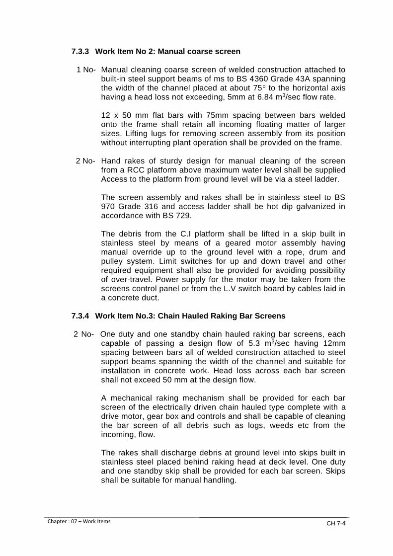
Chapter : 07 – Work Items CH 7-4
7.3.3 Work Item No 2: Manual coarse screen
1 No- Manual cleaning coarse screen of welded construction attached to built-in steel support beams of ms to BS 4360 Grade 43A spanning the width of the channel placed at about 75o to the horizontal axis having a head loss not exceeding, 5mm at 6.84 m3/sec flow rate. 12 x 50 mm flat bars with 75mm spacing between bars welded onto the frame shall retain all incoming floating matter of larger sizes. Lifting lugs for removing screen assembly from its position without interrupting plant operation shall be provided on the frame.
2 No- Hand rakes of sturdy design for manual cleaning of the screen
from a RCC platform above maximum water level shall be supplied Access to the platform from ground level will be via a steel ladder.
The screen assembly and rakes shall be in stainless steel to BS
970 Grade 316 and access ladder shall be hot dip galvanized in accordance with BS 729.
The debris from the C.I platform shall be lifted in a skip built in stainless steel by means of a geared motor assembly having manual override up to the ground level with a rope, drum and pulley system. Limit switches for up and down travel and other required equipment shall also be provided for avoiding possibility of over-travel. Power supply for the motor may be taken from the screens control panel or from the L.V switch board by cables laid in a concrete duct.
7.3.4 Work Item No.3: Chain Hauled Raking Bar Screens 2 No- One duty and one standby chain hauled raking bar screens, each
capable of passing a design flow of 5.3 m3/sec having 12mm spacing between bars all of welded construction attached to steel support beams spanning the width of the channel and suitable for installation in concrete work. Head loss across each bar screen shall not exceed 50 mm at the design flow. A mechanical raking mechanism shall be provided for each bar screen of the electrically driven chain hauled type complete with a drive motor, gear box and controls and shall be capable of cleaning the bar screen of all debris such as logs, weeds etc from the incoming, flow. The rakes shall discharge debris at ground level into skips built in stainless steel placed behind raking head at deck level. One duty and one standby skip shall be provided for each bar screen. Skips shall be suitable for manual handling.

Chapter : 07 – Work Items CH 7-5
The ranking assembly shall be controlled by differential pressure transducers mounted upstream and downstream of the screens for start and stop of the rakes on rising and falling pressure differential. Overriding manual control and local and remote electrical controls from distribution board and PLC/SCADA system shall also be provided. The control and operating facilities shall be designed so that the two screens can be operated simultaneously from a central control panel. In the event of debris free water passing through the screen for long periods a timer will ensure that the rakes are turned three times a day. Raking assembly shall be removable in the event of failure so that bar screens can be cleaned by hand raking. Two sets of hand rakes of sturdy design shall be provided. The screen assembly and rakes including hand rakes shall be in stainless steel to BS 970 Grade 316. In the event of failure of the screen, provision shall be made for lifting the whole screen assembly for maintenance without interrupting flow. The Contractor shall provide control and electric cables in concrete ducts between pumping station and the screen control switch gear.
7.3.5 Work Item No. 4: Central flow Band Screen
2 No- One duty and one standby central flow band screens spanning, the width of the channel each capable of passing a design flow of 5.3 m3/sec having a stainless steel 2.0 mm square aperture mesh suitable for removal of filamentia from weeds and floating algae matter present in raw water without causing blockage of the screen. Head loss across each screen and back opening, when clean shall not exceed 170mm at duty flow.
Each band screen shall be capable of two speed operation complete with motor, gear box and controls and shall be automatically controlled by differential pressure signals from pressure transducers mounted upstream and downstream of each screen monitoring the head loss across the screen.
The control mechanism will ensure that when the pressure difference across the screen starts to rise the screen will start and turn at slow speed and the washwater actuated isolating valve will open and allow washwater to wash the screen. If pressure difference continues to rise, the screen will switch to fast speed automatically with washwater still on. Any further rise in pressure differential will alarm and trip the screen. In the event of debris-free water passing through the screen for long periods, a timer will

Chapter : 07 – Work Items CH 7-6
ensure that the screen turns at least three times a day. Overriding manual control for local and remote operation shall be provided for slow and fast speeds Control and operation of the screen from PLC/SCADA system shall also be provided. Band screen shall be washed by high pressure water jets each delivering a minimum 50 l/min at the required pressure with jet spacing of 140mm approximately. Washwater shall be taken from the pump delivery main. The Contractor shall provide all necessary pipe work, valves, a duplex filter with a mesh sized to prevent blocking of jets, duty and standby pressure reducing valves, pressure gauges and motorized control having facility for manual operation.
The Contractor may propose alternative mesh cleaning system provided that it is simpler, better and more effective.
Band screen control and washing facilities shall be designed so that the two screens can be operated simultaneously from a central control panel or from PLC/SCADA system.
Screen washing shall discharge via a chute to a debris pit where solids shall be collected in a skip made in stainless steel suitable for manual handling and wash water returned to screen chamber at inlet to the screen. One duty and one standby skip shall be supplied with each screen.
The Contractor shall provide washwater pipe work and control and electric cabling in concrete ducts between pumping station and the screen channel. Necessary hooks, tackles etc shall be provided to lift the screening assembly without interrupting the plant operation.
7.3.6 Work Item No. 5: Penstocks
4 No- Rectangular faced penstocks of sectional frame for an operational off-seating pressure of one bar exceeding the top of the door.
The penstocks shall be suitable for installation in the two screening streams, each having two penstocks one located upstream and the other downstream of the screens for isolation of the screening stream whenever required for maintenance works.
Each penstock shall be capable of passing a design flow of 5.3m3/sec and shall be of adequate width to allow unhampered and streamlined flow to and from the screens in all stages of operation from 25% to 100% of the flow. The penstocks shall be provided with extension shafts and headstocks for manual operation from the floor level. Motorized operation gear and accessoriness shall also be provided.
The penstocks shall be of the flat back type with rising stems of stainless steel and guide rails for channel mounting frames and gates made of epoxy coated mild steel, adjustable wedges having
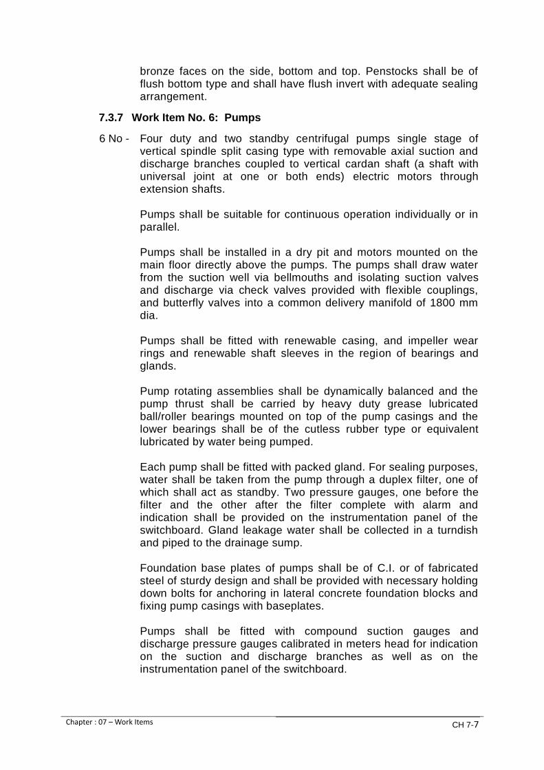
Chapter : 07 – Work Items CH 7-7
bronze faces on the side, bottom and top. Penstocks shall be of flush bottom type and shall have flush invert with adequate sealing arrangement.
7.3.7 Work Item No. 6: Pumps
6 No - Four duty and two standby centrifugal pumps single stage of vertical spindle split casing type with removable axial suction and discharge branches coupled to vertical cardan shaft (a shaft with universal joint at one or both ends) electric motors through extension shafts.
Pumps shall be suitable for continuous operation individually or in
parallel. Pumps shall be installed in a dry pit and motors mounted on the
main floor directly above the pumps. The pumps shall draw water from the suction well via bellmouths and isolating suction valves and discharge via check valves provided with flexible couplings, and butterfly valves into a common delivery manifold of 1800 mm dia.
Pumps shall be fitted with renewable casing, and impeller wear
rings and renewable shaft sleeves in the region of bearings and glands.
Pump rotating assemblies shall be dynamically balanced and the
pump thrust shall be carried by heavy duty grease lubricated ball/roller bearings mounted on top of the pump casings and the lower bearings shall be of the cutless rubber type or equivalent lubricated by water being pumped.
Each pump shall be fitted with packed gland. For sealing purposes,
water shall be taken from the pump through a duplex filter, one of which shall act as standby. Two pressure gauges, one before the filter and the other after the filter complete with alarm and indication shall be provided on the instrumentation panel of the switchboard. Gland leakage water shall be collected in a turndish and piped to the drainage sump.
Foundation base plates of pumps shall be of C.I. or of fabricated
steel of sturdy design and shall be provided with necessary holding down bolts for anchoring in lateral concrete foundation blocks and fixing pump casings with baseplates.
Pumps shall be fitted with compound suction gauges and
discharge pressure gauges calibrated in meters head for indication on the suction and discharge branches as well as on the instrumentation panel of the switchboard.

Chapter : 07 – Work Items CH 7-8
The estimated total head for the pumps is 66.0 m but the Contractor shall determine the actual total head on the basis of his layout, designs and equipment supplies including that of the pumping main shown on the Conceptual Drawings. Motors shall drive pumps by means of cardan shafts with spline universal couplings.
The contractor shall present the head curves for the pumps with
clearly marked duty points and the Net Positive Suction Head, required, (NPSH required) curves. The bidder shall clearly calculate and present the Net Positive Suction Head, available, (NPSH available). In order to calculate the NPSH available, pump placement relative to the minimum water level, minimum water level on the suction side, entrance and exit losses in suction pipe, frictional losses, vapor pressure, and any other relevant information would be very clearly presented.
The contractor shall check the minimum Submergence of the pump
intake to reduce the probability that strong free surface area core vortices will not occur. Pump bearing temperature sensor shall be provided
Chemical analysis report given in Annexure-A may be referred for
pump design. Characteristics of one pump shall be:
Duty discharge rate : 1.32 m3 / sec (25 imperial MGD)
Duty head : 66.0 m estimated and to be tested in accordance with BS 5316: Part 2 (ISO 3555)
Manometric efficiency : 89% minimum
Power required at pump shaft : 850kW approximately
Speed of pump shaft : 740 rpm approximately
Working pressure : 10 bars
Test pressure : 15 bars or surge pressure whichever is greater
Suction pipe work dia. : 900 mm
Delivery pipe work dia. : 900 mm

Chapter : 07 – Work Items CH 7-9
Suction/ delivery flanges to : BS 4504, PN 16
NPSH Required : To be provided by Bidder
NPSH Available : To be provided by Bidder
Submergence : To be provided by bidder
Material of construction shall be as follows or superior:
Pump casing and foundation : grey cast iron to BS 1452 grade 220
Pump impeller : stainless steel
Pump shaft : stainless steel
Shaft sleeves : chrome steel
Casing and impeller wear rings
: special bronze to BS 1400
Cardan shaft : Steel
The bidder shall show following levels on his Tender Drawings: a. Motor room floor level b. Pump room floor level c. Suction channel bed level d. Maximum, average and minimum levels in the suction
channel e. Height of ceiling from floor level of motor room The bidder shall fix the centre line of his pumps such that the NPSHa is sufficiently greater than the NPSHr at the minimum suction channel level so that a cushion of 2.0 m is available for pumping without vortex formation and cavitation free operation. This provision is essential in view of frequent level drops in the suction channel. Pump operation shall be controlled from the 11 kV motor panels and the PLC/SCADA control panel. Motors shall be started by push buttons from the control panels. Level electrodes shall be installed in the pump suction well to provide alarm and to stop pumps and inhibit them from starting in the event of low water level in the suction well. Timers shall also be incorporated to ensure that pumps do not stop simultaneously in the event, of low water level.

Chapter : 07 – Work Items CH 7-10
Motor stools shall be mounted on sole plates and should be easily removable to enable complete pump assemblies to be lifted through the motor floor opening. The Contractor shall provide extension shaft with flexible couplings and intermediate bearings, if required. In case of provision of intermediate bearings steelwork supports shall be so arranged that not more than one bearing is supported from each steel structure. Facilities for greasing intermediate bearings shall be provided by means of access ladders.
Non-reversing ratchets shall be provided to prevent reverse rotation of pump/motor assemblies in the event of reverse flow during periods when non-return valves remain open for bypassing surge pressures.
7.3.8 Work Item No. 7: Suction branches
6 No- Suction branches each of 900 mm dia, for vertical pumps hydraulically pressure tested to 15 bars for a maximum working pressure of 10 bars and each branch capable of passing a design flow of 1.32 m3 / sec.
The pipe work including specials, bends and flexible slip out joints shall be in mild steel of minimum wall thickness 10 mm and minimum grade of steel Grade B.
Work Item No.7 shall comprise following Sub Work Items. The Contractor may claim payment against each Sub Work Item, if he so desires.
Each suction branch shall comprise of:
S. No.
Sub-Work Item
Quantity Brief description
1 7-1 1
Ductile iron bellmouth to BS 4772 or equivalent for grouting in concrete wall and for connection with gate valve of 900 mm dia.
2 7-2 1
900 mm dia. gate valve complete with integral bypass having a gate valve of 100 mm and provided with an electrically operated actuator type A, complying to Clause 2.32 of the Specification, Volume -II.
3 7-3 1 900 mm dia. flexible slipout joint with seal applied between collars and bolt fitted in-between butterfly valve and conical pipe.
4 7-4 1
Flanged MS conical pipe of length to connect suction branch of the pump with the flexible slipout joint having a minimum wall thickness of 10 mm. Minimum grade of steel shall be
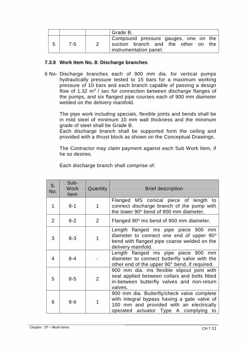
Chapter : 07 – Work Items CH 7-11
Grade B.
5 7-5 2 Compound pressure gauges, one on the suction branch and the other on the instrumentation panel.
7.3.9 Work Item No. 8: Discharge branches 6 No- Discharge branches each of 900 mm dia. for vertical pumps
hydraulically pressure tested to 15 bars for a maximum working pressure of 10 bars and each branch capable of passing a design flow of 1.32 m3 / sec for connection between discharge flanges of the pumps, and six flanged pipe courses each of 900 mm diameter welded on the delivery manifold.
The pipe work including specials, flexible joints and bends shall be
in mild steel of minimum 10 mm wall thickness and the minimum grade of steel shall be Grade B.
Each discharge branch shall be supported form the ceiling and provided with a thrust block as shown on the Conceptual Drawings.
The Contractor may claim payment against each Sub Work Item, if he so desires.
Each discharge branch shall comprise of:
S. No.
Sub-Work Item
Quantity Brief description
1 8-1 1 Flanged MS conical piece of length to connect discharge branch of the pump with the lower 90o bend of 900 mm diameter.
2 8-2 2 Flanged 90o ms bend of 900 mm diameter.
3 8-3 1
Length flanged ms pipe piece 900 mm diameter to connect one end of upper 90o bend with flanged pipe coarse welded on the delivery manifold.
4 8-4 - Length flanged ms pipe piece 900 mm diameter to connect butterfly valve with the other end of the upper 90° bend, if required.
5 8-5 2
900 mm dia. ms flexible slipout joint with seal applied between collars and bolts fitted in-between butterfly valves and non-return valves.
6 8-6 1
900 mm dia. Butterfly/check valve complete with integral bypass having a gate valve of 100 mm and provided with an electrically operated actuator Type A complying to

Chapter : 07 – Work Items CH 7-12
S. No.
Sub-Work Item
Quantity Brief description
Clause 2.32 of the Specification, Volume –II.
7 8-7 1 900 mm dia., non-return valve.
8 8-8 2 Compound pressure gauges, one on the discharge branch and the other on the instrumentation panel.
9 8-9 -
Surge computations by computer programming shall be based on actual site conditions including the hydraulics of the pumping main shown on Conceptual Drawings and shall be submitted by the Contractor for Employer’s review. The Contractor shall propose protective system or additional equipment, if required, for mitigating surge pressures and for safe operation of the pumping system without any extra cost to client. All connections to rising main shall be checked for safety against surge. Compound pressure gauges, one on the discharge branch and the other on the instrumentation panel shall be installed. Provision of surge vessels may be considered, if required by the Contractor
7.3.10 Work Item No. 9: Delivery manifold Work Item No.9 shall comprise following Sub Work Items. The Contractor may claim payment against each Sub Work Item, if he so desires.
S. No.
Sub-Work Item
Quantity Brief description
1 9-1 Length
Delivery manifold of 1800 mm dia. made of minimum 15 mm ms plates with welded on six flanged pipe courses each of 900 mm dia. having a minimum wall thickness of 10 mm for connecting six discharge branches, hydraulically tested to 15 bars for a maximum working pressure of 10 bars and capable of passing a design flow of 5.3m3/sec. Two flanged pipe connections of 450 mm dia. of ms having a minimum wall thickness of 10 mm shall also be provided for connecting pressure relief valves minimum Grade of steel shall be Grade B.

Chapter : 07 – Work Items CH 7-13
S. No.
Sub-Work Item
Quantity Brief description
The manifold shall be flanged at both ends. One end shall have a blank flange and the other end shall be connected to 1800 mm dia. butterfly valve.
2 9-2 2 Compound pressure gauges one on the manifold and the other on the instrumentation panel.
3 9-3 2 450 mm dia. butterfly valves for manual operation for isolating pressure relief valves.
4 9-4 2 450 mm dia. pressure relief valves for releasing transient surge pressures above 7 bars or as required.
5 9-5 1
1800 mm dia. MS flexible slipout joint with seal applied between collars and bolts fitted in-between butterfly valve and delivery manifold flanges.
6 9-6 1 1800 mm dia. butterfly valve for manual operation with integral bypass having a gate valve of 150 mm diameter.
7.3.11 Work Item No. 10: Delivery main
Work Item No.10 shall comprise of following Sub Work Items. The Contractor may claim payment against each Sub Work Item, if he so desires.
S. No.
Sub-Work Item
Quantity Brief description
1 10-1 Length
Delivery main of 1800 mm dia. made of minimum 15 mm ms plates for connecting with delivery manifold and delivering pumped water to a dedicated rising main of 1800 mm dia. Minimum grade of steel shall be Grade B. The main shall be hydraulically tested to 15 bars for a maximum working pressure of 10 bars and shall be capable of passing a design flow of 5.3 m3/sec. The Contractor will ensure that for connection with the existing rising main, the delivery main will pass the existing common manifold and rising main No.4
2 10-2 2 1800 mm dia. flexible slipout joint with seal applied between collars and bolts fitted in

Chapter : 07 – Work Items CH 7-14
S. No.
Sub-Work Item
Quantity Brief description
between flowmeter and delivery main flanges.
3 10-3 2 1800 mm dia. butterfly valve for manual operation with integral bypass having a gate valve of 100 mm diameter.
4 10-4 1
1800 mm dia. electromagnetic flowmeter for a designed flow rate of 5.3 m3/sec complete with flow signal converters/transmitters for displaying flow rate and total flow inside the flowmeter chamber as well as on the pump station panel and SCADA. The flowmeter shall be installed in a RCC chamber in accordance with manufacturer’s instructions and with a minimum of five diameters straight pipe upstream and two diameters downstream.
5 10-5 2 1800 mm dia. flanged MS bends as shown on Conceptual Drawings.
6 10-6 1 Double acting automatic air release valve with gate valve of 100 mm dia. mm in a RCC chamber at suitable location.
7.3.12 Work Item No. 11: Drain pipe
1 -600 mm dia. butterfly valve for manual operation for the drain pipe work by passing water in the pump sump.
1 - 600 mm dia. flexible slip out joint with seal applied between collars and bolts fitted in between pipe and butterfly valve.
Length - 600mm dia. MS pipe work of minimum 8 mm wall thickness to act as drain pipe discharging into pump sump for emptying delivery main and manifold when required.
7.3.13 Work Item No. 12: Electric overhead gantry crane
1 No- Electric overhead traveling crane comprising a bridge assembly
with hoist and having cross traverse and long travel facilities complete with all necessary gantry beams, rails and fixings to the building structure for a safe working load of 10 ton to facilitate handling of all equipment such as 11 KV motors, electric panels, pumps, valves and pipework installed in the pump house building with controls by means of divorced pendant.
An access platform 1000 mm wide in chequered in aluminum alloy
shall be provided complete with hand railing on one side of the crane to facilitate maintenance of the pump house ceiling and

Chapter : 07 – Work Items CH 7-15
lighting installations. The trolley shall have guard rails to provide access for crane maintenance.
One fixed access ladder with guards to provide a safe route to
crane platform shall be included at one end of the motor room. Load chains shall be of sufficient length to enable the hook to be
lowered to the bottom of the pump chamber and shall be provided with a chain collecting box to hold the slack chain.
Adequate quantity of lifting beams, slings and all other tackle
needed for handling all equipment shall be supplied with the crane. The Contractor shall provide all necessary contactors, control
cubicles and protection equipment necessary to operate the crane and provide adequate electrical protection against overload, phase and earth fault and failsafe protection in the event of an interruption in the power supply. All necessary ladders and platforms beside those specified above or in the Specification shall be provided.
7.3.14 Work Item No. 13: Dewatering pumps
2 No- Dewatering pumps of minimum 20 l/sec discharge at 10 m head,
one duty and one standby, shall be provided in a sump in the pump chamber to pump gland leakage and drainage water during maintenance of pumps and pipework to the suction well. The pumps shall be complete with pipework, valves and float type level controls for automatic/manual and start/stop operations.
7.3.15 Work Item No.14: Access ladders, platforms and plate flooring
Work Item No.14 shall comprise of following Sub Work Items. The Contractor may claim payment against each Sub Work Item, if he so desires:
`
S. No.
Sub-Work Item
Quantity Brief description
1 14-1 lot
Steel plate flooring covers on all openings and cable ducts in motor room of Durbar or non-slip pattern of minimum 4.5 mm thick steel plate hot dip galvanized after fabrication to BS 729.
2 14-2 lot
Hand railing consisting of double bar forged steel standards with tubular rails hot dip galvanized in accordance with BS 729 shall be provided around inlet chambers, screen chamber, pump sump, valve and flow meter chambers and other areas as required. All hand railing at ground floor viz motor room including that of balcony shall be

Chapter : 07 – Work Items CH 7-16
S. No.
Sub-Work Item
Quantity Brief description
stainless steel to BS 970 Grade 316
3 14-3 lot
Access ladders and platforms of minimum width 1000 mm made in checkered aluminum alloy in accordance with BS 1470 material H 30 TB to be provided in the pump basement (dry-pit) for access to all six pumps and all suction, discharge and non-return valves for facilitating O&M works as shown on Conceptual Drawings. Hand railing consisting of double ball forged steel standards with tubular rails hot dip galvanized in accordance with BS 729 shall be provided where required.
4 14-4
lot
Access ladders of sturdy design built-in steel, hot dip galvanized to BS 729, for installation in valve /flowmeter chambers, screening stream chambers, inlet chambers and pump sump etc.
7.3.16 Work Item No.15: Replacement of air valves existing 1800mm dia. rising main of existing phase 2, Dhabeji Pump House.
All existing double acting Air valves fixed on the rising main shall be removed and replaced with new double acting air valves similar to existing design and specifications of European or USA make as approved by the Employer.
7.4 Employer’s Requirements: Electrical Works
7.4.1. General
Preliminary power demand estimates indicate that the pumping station will require a total supply of approximately 10.0 MVA at a supply voltage of 11 kV. Karachi Electric Supply Corporation, the local power supply authority may be able to meet this demand from their 132 / 11 kV Dhabeji grid station by laying 11 kV cable feeders upto a substation / switch room to be located inside the pump house premises. This sub-station shall be constructed under the Contract and will be handed over to K-ELECTRIC for housing their 11 kV switchgear and metering equipment. The Contractor shall lay two 11 kV cable feeders of minimum 300 sq-mm size from the sub-station to the two incoming panels of the 11 kV switchboard to be provided in the pump house building as shown on the Conceptual Drawings. A bus coupler will ensure that, in case of failure or

Chapter : 07 – Work Items CH 7-17
isolation of one feeder, the healthy feeder can supply power to any four duty pumps and one transformer. 6 No. 11 kV motors of vertical design shall drive the pumps installed in a dry-pit directly below the motors. Four pumping sets shall be working and two will be standby Power factor correction equipment shall maintain the power factor above 0.90 lagging for economizing, the operational cost. 2 No. 11 KV/415 V, 250 KVA, transformers, one working and one standby, shall meet the LV power requirement of the pump house and other services provided at Site. A PLC/SCADA system shall provide outputs to annunciation & control of all desired operations and perform all logical functions for complete monitoring and automatic operation of the pump house for acquisition and display of the desired data. 7.4.2. Work Item No.15: 11 kV switchboard
The 11 KV switchboard shall comply with the K-ELECTRIC specifications: 11 kV sheet steel, floor mounting, totally enclosed, compartmentalized, fully interlocked, air insulated, indoor type, suitable for operation at 11 kV, 75 kV BIL, 3 phase, 50 Hertz supply, completely wired and tested in accordance with relevant latest IEC standard or equivalent having rated peak withstand current of 45 kA, rated short circuit and comprising breaking current (1 sec) of 18 kA and rated short circuit making current of 45 kA. 2 No - Incoming panels from K-ELECTRIC each with:
1- Sheet steel floor mounting, housing.
1- Set of 3 phase, 1250 amps rating, HDHC heat shrunk, Raychem sleeved, round edged copper busbars and all joints silver plated.
6- Single pole fixed and moving type isolating contacts having isolating facility in each phase.
1- Set of automatic safety shutters having padlocking facility.
1- 1250 amps, motor operated having rupturing capacity of 20 kA / 1 sec, triple pole, vacuum circuit breaker mounted on a rollout truck to facilitate vertical dropdown isolation and horizontal withdrawal.
1- Circuit breaker lowering mechanism fitted with removable operating handle.
1- Circuit breaker hand/motor charged spring closing mechanism of the trip free pattern complete with:

Chapter : 07 – Work Items CH 7-18
a. Voltage operated release.
b. Set of ON/OFF/EMERGENCY trip push buttons.
c. Mechanical ON/OFF position indicators.
d. Spring closing hand charging mechanism
The operating mechanism and stored energy shall allow the following sequence: 0-3 min - co-3 min - co
1- Set of indication lamps.
3 - Current transformers having ratio of 600/5/5 amps and with: Core 1: 10VA, 1 M 5 Core 2: 15 VA, 5 P 20
1- 96 x 96 mm Ammeter scaled 0-600 Amp having suitable overload scale and with Ammeter selector switch, 3 way and off.
1- 96 x 96 mm Voltmeter scale 0-15 kV with voltmeter selector switch, 3 way and off.
1- 96 x 96 mm CT and PT operated power factor meter.
2- Single pole cast resin voltage transformers, ratio 11000/√13 /110√3, 200 VA, accuracy class-l, 75 kV BIL, with primary protection fuses.
1- KWh meter, 3 phase, 3 wire with MD1 (30 min) suitable for CT and
PT connections of 5A, 110 V and 50 Hz.
1- kVArh meter, 3 phase, 3 wire suitable for CT and PT connections of 5A, 110 V and 50 Hz.
1- 11 kV capacitive voltage detector in yellow phase on the circuit side.
1- Earthing switch equal to the rating of the switchgear.
1- Set of support insulator with creepage distance of 350 mm.
1- Auxiliary relay for contact multiplying. 1- 3 phase O/C. E/F & S/C relay (50/51/51N) with selectable tripping
curve and three independent O/C, E/F & S/C thresholds including communication ports.

Chapter : 07 – Work Items CH 7-19
1- Under voltage relay.
1- Over voltage relay.
1- Set of instrument fuses.
2- Sets of electrical & mechanical castel inter locks.
1- Operation counter meter
1- Anti-condensation heater with thermostat.
1- Designation label. 1 No - Bus coupler complete with:
1- Sheet steel floor mounting housing.
1- Set of 3 phase 1250 Amps rating HDHC heat shrunk, sleeved, round edged copper busbars and all joints silver plated.
6- Single pole fixed and moving type isolating contacts having isolating facility in each phase.
1- Set of automatic safety shutters having padlocking facility.
1- 1250 Amps motor operated having rupturing capacity as specified
for incoming panel, triple pole, vacuum circuit breaker mounted on a rollout truck to facilitate vertical dropdown isolation and horizontal withdrawal.
1- Circuit breaker lowering mechanism fitted with removable operating handle.
1- Circuit breaker hand/motor charged spring closing mechanism of the trip free pattern complete with. a. Voltage operated release.
b. Set of ON/OFF/EMERGENCY trip push buttons.
c. Mechanical ON/OFF position indicators.
d. Spring closing hand charging mechanism.
1- Set of ON/OFF indication lamps.
1- Set of electrical and mechanical interlocks.
1- Anti-condensation heater with thermostat.
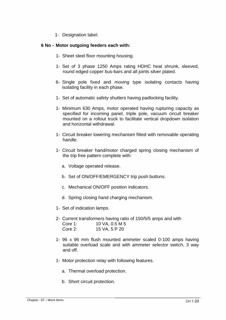
Chapter : 07 – Work Items CH 7-20
1- Designation label.
6 No - Motor outgoing feeders each with:
1- Sheet steel floor mounting housing.
1- Set of 3 phase 1250 Amps rating HDHC heat shrunk, sleeved, round edged copper bus-bars and all joints silver plated.
6- Single pole fixed and moving type isolating contacts having isolating facility in each phase.
1- Set of automatic safety shutters having padlocking facility.
1- Minimum 630 Amps, motor operated having rupturing capacity as
specified for incoming panel, triple pole, vacuum circuit breaker mounted on a rollout truck to facilitate vertical dropdown isolation and horizontal withdrawal.
1- Circuit breaker lowering mechanism fitted with removable operating handle.
1- Circuit breaker hand/motor charged spring closing mechanism of the trip free pattern complete with: a. Voltage operated release.
b. Set of ON/OFF/EMERGENCY trip push buttons.
c. Mechanical ON/OFF position indicators.
d. Spring closing hand charging mechanism.
1- Set of indication lamps.
2- Current transformers having ratio of 150/5/5 amps and with
Core 1: 10 VA, 0.5 M 5 Core 2: 15 VA, 5 P 20
1- 96 x 96 mm flush mounted ammeter scaled 0-100 amps having suitable overload scale and with ammeter selector switch, 3 way and off.
1- Motor protection relay with following features. a. Thermal overload protection.
b. Short circuit protection.

Chapter : 07 – Work Items CH 7-21
c. Earth fault protection.
d. Stalled rotor / mechanical jam.
e. Prolonged start.
f. Time between starts.
g. Speed switch input.
h. Programmable scheme logic.
i. Eight RTDs.
1- 11 kV capacitive voltage detector in yellow phase on the circuit side.
1-96 x 96 mm flush mounted CT and PT operated power factor meter.
1- 96 x 96 mm flush mounted operation hour counter.
1- Earthing switch, for short circuiting and earthing of disconnected system, should be rated as specified for incoming panel. It should be 3 poles with snap action closing mechanism and mechanical interlock with switching device and shall be equipped with 4 pole auxiliary switch.
1- Hooter
1- Set of instrument fuses.
1- Operation counter meter.
1- Remote/local selector switch.
1- Anti-condensation heater with thermostat.
1- Designation label.
Note: Provision to be made for remote control of pumps from PLC/SCADA control desk.
2 No - Transformer feeders each with:
1- Sheet steel floor mounting housing.
1- Set of 3 phase, 1250 Amps rating HDHC heat shrunk, sleeved, round edged copper bus-bars and all joints silver plated.

Chapter : 07 – Work Items CH 7-22
6- Single pole fixed and moving type isolating contacts having isolating facility in each phase.
1- Set of automatic safety shutters having padlocking facility.
1- Minimum 630 Amps, motor operated having rupturing capacity of
20 kV/1 sec, triple pole, vacuum circuit breaker mounted on a rollout truck to facilitate vertical dropdown isolation and horizontal withdrawal.
1- Circuit breaker lowering mechanism fitted with removable operating handle.
1- Circuit breaker hand/motor charged spring closing mechanism of the trip free pattern complete with: a. Voltage operated release.
b. Set of ON/OFF/EMERGENCY trip push buttons.
c. Mechanical ON/OFF position indicators.
d. Spring closing hand charging mechanism.
1- Set of ON/OFF indication lamps.
2- Current transformers, ratio of 50/5/5 amps having:
Core 1: 10 VA, 1 M 5 Core 1: 15 VA, 5 P 20
1- 96 x 96 mm flush mounted ammeter scaled 0-50 amps with ammeter selector switch 3 way and off.
1- 3 Phase digital 0/C, E/F and S/C relay (50/5/5IN) with selectable
3 tripping curves and 3 independent 0/C, E/F & S/C thresholds including communicating ports.
1- Earthing switch for short circuiting and earthing of disconnected
system should be rated for peak current of 20 kA at 12 kV. It should be 3 pole with snap action closing mechanism and interlocking with switching device and shall be equipped with 4 pole auxiliary switch.
1- 96 x 96 mm) flush mounted operation hour counter.
1- Set of instrument fuses.
1- Anti-condensation heater with thermostat.
1- Designation label.

Chapter : 07 – Work Items CH 7-23
7.4.3. Work Item No.16: Capacitors
6 No- 11 kV capacity 350 kVAr power factor correction units each equipped as under:
a. Medium voltage capacitor for power factor correction to be provided
with self-healing dielectric and very low losses suitable for direct coupling with motor terminals with backup fuses and fuse bases to be placed in a compartmentalized enclosure having IP42 protection close to the11 kV switchgear.
b. Capacitor shall be suitable for continuous operation at motor output rating plus a 3.5% margin for maintaining, power factor above 0.90 lagging.
c. The actual active capacitor element shall consist of a large number of high quality, self-healing round MKP elements, which are wired to each other.
d. Capacitor shall not contain chlorinated substances or presents
ecological problems and shall be in accordance with IEC 60871.
e. Capacitor containers shall be of sealed construction stainless steel suitable for outdoor / indoor use providing efficient heat transmission.
f. Porcelain bushings shall be suitable for 11 kV voltage connections and
for polluted conditions.
g. Dielectric losses shall be below 0.20 W/kVAr at ambient temperature. Total capacitor losses shall not exceed 0.25 W/KVAr
h. Capacitor residual voltage should reduce to below 75 V within 10
minutes after disconnection from the circuit.
i. Power factor improvement relay shall maintain the power factor between 0.9 lagging and unity and shall not attain leading power factor. It shall also rotate the use of capacitors to maintain equal usage for all capacitors.
j. Cooling / ventilating arrangement shall be provided.
k. Life expectancy (permitted failure rate) shall be greater than 100,000.
l. Power factor improvement capacitors shall not be required if the
variable frequency drive (VFD) maintains the power factor above the Minimum required.

Chapter : 07 – Work Items CH 7-24
7.4.4. Work Item No.17: LV switch board
415 V 3 phase, 4 wire, 50 Hz sheet steel, floor mounting, totally enclosed, compartmentalized fully interlocked, air insulated type suitable for operation on low voltage supply, completely wired and tested in accordance with relevant IEC standard or equivalent having rupturing capacity of 50 kA/1 sec, equipped as under: 2 No - Incoming panels from transformers each with: 1- Sheet steel floor mounting housing. 1- Set of bus-bars, 400 amps rating. HDHC, heat shrunk, sleeved,
round edged copper bus-bars and all joints silver plated. 1- Set of automatic safely shutters having padlocking facility. 1- 400 amps triple pole, withdrawable, quick make/break, moulded
case circuit breaker with adjustable thermal and magnetic trip devices for overload and short-circuit protection and complete with under voltage release.
1- 96x96 mm, flush mounted CT operated ammeter scaled 0-400 amps along with a 3-way and off selector switch.
1- 96x96 mm flush mounted voltmeter, scaled 0-600 volts along with
a position selector switch. 3- CTs of ratio 400/5 CTs shall be of 5VA, class-1 for metering. 1- Earth leakage relay with an appropriate CT. 2- ON/OFF indication lamps. 1- Set of electro-mechanical key interlock. 1- Set of instrument fuses. 1- Anti-condensation heater with thermostat. 1- Designation label.
1 No- Bus coupler complete with: 1- Sheet steel floor mounting housing. 1- Set of bus-bars, 600 amps rating HDHC heat shrunk Raychem
sleeved, round edged copper bus-bars and ail joints silver plated. 1- Set of automatic safety shutters having padlocking facility.

Chapter : 07 – Work Items CH 7-25
1- 400 amps, triple pole, withdraw-able, quick make/break, moulded case circuit breaker with adjustable thermal and magnetic trip devices for overload and short-circuit protection and complete with under voltage release.
2- ON/OFF indication lamps. 1- Set of electro-mechanical key interlock. 1- Anti-condensation heater with thermostat. 1- Designation label. Outgoing circuits:
The outgoing circuit breakers panel shall as a minimum be equipped as under:
1- Sheet steel floor mounting housing complete in all respects and
with anti-condensation heater, thermostat and designation label. 1- Set of bus-bars, 400 amps rating, HDHC, heat shrunk, Raychem
sleeved, round edged copper bus-bars and all joints silver plated.
Triple pole moulded case circuit breakers:
LV circuit breakers shall comply with IEC 60947 and as a minimum be equipped as under:
56- Triple pole moulded case circuit breakers with adjustable trip device for overload and fixed magnetic short-circuit protection and complete in all respects and each feeder, having a designation label and “ON” indicator for following applications:
MCCB’s shall comply with IEC 60947. 6- 32 amps MCCBs for motor control and anti-condensation heaters. 6- 16 amps MCCBs for suction valve actuators. 6- 16-amps MCCBs for delivery valve actuators. 1- 16-amps MCCB for manual screen. 2- 32 amps MCCBs for bar screens. 2- 32 amps MCCBs for band screens. 1- 16 amp MCCB for submersible pumps. 1- 25 amp MCCB for PLC/SCADA system.

Chapter : 07 – Work Items CH 7-26
1- 25 amp MCCB for battery chargers. 12- 16 amp MCCBs for 3 phase exhaust fans. 6- 32 amp MCCBs for 3 phase industrial sockets. 1- 16 amp MCCB for electric overhead travelling crane. 3- 63 amp MCCBs as spare. 4- 32 amp MCCBs as spare. 4- 25 amp MCCBs as spare.
The quantities of MCCBs specified are the minimum. The Contractor may increase the quantity according to his design
Minimum number of single pole miniature circuit breakers:
MCB’s shall comply IEC 60898 and as a minimum be equipped as under:
Lot - 16 amp single pole miniature circuit breakers with designation labels for internal and external illumination of the pumping station.
12- 32 amp single pole miniature circuit breakers with designation
labels for single phase, 3 pin - switch-socket - outlets. 6- 32 amp single pole miniature circuit breakers as spare. 6- 16 amp single pole miniature circuit breakers as spare.
7.4.5. Work Item No.18: Instrumentation panel
Sheet steel, floor mounting housing for following gauges and instruments complete with transmitters for monitoring with PLC. 4- Digital type level indicator for 2 No chain hauled raking bar screens and
2 No central flow band screens. 1- Digital type level indicator for suction well. 6- Digital type pressure gauges for pump suction branches. 6- Digital type pressure gauges for pump discharge branches. 1- Digital type pressure gauge for common manifold. 12- Digital type pressure gauges for 6 No sealing water duplex filters. 1- Digital type flow indicator complete with totalizer

Chapter : 07 – Work Items CH 7-27
7.4.6. Work Item No.19: 11 kV motors
6No- Squirrel cage induction motors for direct on line starting suitable for operation on 11 kV, 3 phase, 50 Hz supply and for coupling with pumps through extension shafts described under clause 4.2.3: and Work Item No 6 and each complying with following specifications.
Output of motor: Approximately 1000 kW but should be
10% in excess of power required by the pump at duty point and 5% in excess at run-out condition.
Speed: Approximately 740 rpm. Efficiency at full load: Not less than 96% Power factor at full load: Approximately 0.82 lagging Motor Design: Vertical type with two bearing end shields,
with antifriction bearings of ball/roller type, with one cable end box of suitable size, with gland, one set of anti humidity heater system working on station auxiliary supply of 415 V, 3 phase 50 Hz, totally enclosed, and tube cooled, winding insulation class F and maximum temperature not to exceed that permitted for class B, ambient temperature of operation 50°C and motor suitable for operation in humid and tropical climate, with protection class IP 54 according to IEC 60034. The motor shall be supplied with following accessories:
a. Winding RTDs : 6 No b. Bearing RTDs : 2 No c. Space heater : 1 No
One portable stand shall be provided to enable a motor to be stood in vertical position when removed for maintenance purposes. Temporary motor terminal covers shall also be provided to cover motor terminal studs.
Motors shall be fitted with means for locking rotors to avoid damage occurring to bearings when motors are laid horizontally and to facilitate transportation in this mode.

Chapter : 07 – Work Items CH 7-28
7.4.7. Work Item No.20: 11 kV/415V transformers
2 No - Three phase, all immersed transformers, naturally cooled according to IEC 60076, double wound, core type in sealed tank design with oil conservators and bi-directional flat rollers, suitable for parallel operation and each according to K-ELECTRIC specifications. Main parameters shall be as under:
Rated load : 250 kVA Phases : 3 No load voltage ratio : 11 kV/415 V Off load tap changer : 0 ± 2.5% ± 5% - 7.5% Frequency : 50 Hz Basic Impulse level (BIL) : 75 kV Copper temperature rise (Avg.) : 45oC Oil temperature rise (Max.) : 35oC Peak Ambient air temperature : 50oC Mean max. Temperature (24hr) : 45oC Min. temperature : 0oC Impedance at nominal tap : about 5% Efficiency : Minimum 98.5% Maximum short circuit duration : 2 Secs Vector Group : DY 11 Cooling : ONAN Place of installation : indoor Accessories : 1- breather
1- dial type thermometer with trip contact
7.4.8. Work Item No.21: Exhaust fans
20 No -3 phase exhaust fans, 12 For motor room and 8 for pump basement,
of constant speed, minimum 600 mm sweep, having reverse and

Chapter : 07 – Work Items CH 7-29
forward motion for operation on 415V, 3 phase, 50 Hz supply, with type bearing for noiseless operation.
ON/OFF switch and auto star/delta starter for individual fan shall be mounted on the LV distribution board. The fans shall have stove enamel finish of approved colour and shall be made to Pakistan Standard PS-1 1958. The make shall be Pak, Millat or approved equivalent. Frames for mounting, the fans shall have stove enamel finish and shall be mounted on the walls at designated locations with appropriate sized G.I. nuts and bolts.
The fans shall be protected with G.I .mesh of sturdy design to prevent bird entry.
4 No- Single phase exhaust fans for transformer room, control room,
PLC/SCADA room and battery room of constant speed and 450 mm sweep for operation on 220V, single phase, 50 Hz supply with grooved type bearings for noiseless operation.
ON/OFF witch for individual fan shall be mounted in the respective room. The fans shall have stove enamel finish of approved colour and shall be made to Pakistan standard PSI 1958. The make shall be Pak, Millat or approved equivalent.
The fails shall be louvered type.
2 No- 300 mm sweep exhaust fans suitable for operation on 220V, single
phase, 50 Hz supply of Pak, Millat or any other approved make complete with ON/OFF Switch for installation in bathrooms.
7.4.9. Work Item No.22: PLC/SCADA system
Purpose
PLC shall receive inputs from 11 kV and LV protection and control and will provide outputs to annunciation control for all desired operations and will perform all logical functions.
PLC shall be constructed in modular form having provision for accepting add-on cards and shall be capable of operating without trouble in a temperature range of 0-55°C and relative humidity of 10% to 95%. All incoming cables shall terminate in the cable marshalling area and not directly on the PLC for which a separate housing shall be provided.
Power Supply Unit Power Supply Unit shall be suitable for the specified supply voltage having protection against voltage and frequency fluctuations and harmonics. The unit

Chapter : 07 – Work Items CH 7-30
shall be provided with battery backup for all volatile registers and memory locations to allow retention of data and programs for a period of not less than three months. Inputs / Outputs The Contractor shall determine the number of I/Os to suit operational requirements with an allowance of 25% spare capacity. LED indicators shall be provided to show status of I/Os which shall be individually isolated to prevent system transients and radio interference affecting the normal operation or decoupling shall be provided for I/0 signals.
Central Processing Unit Central Processing Unit shall operate at a speed of operation suitable for carrying out all specified duties and shall have all necessary built-in timers, relays and mathematical functions etc. The processor shall have non-volatile EPROM and a volatile RAM. Allowance shall be made for 25% spare volatile and non-volatile memory. Programming function for the CPU shall be built into the PC. Program entry and modifications shall be possible in mnemonic language, ladder diagram or flow charts. Security arrangement shall be provided to prevent unauthorized tampering with the PLC control.
The contractor shall be responsible to provide Operating System and Application Software on separate media, Preferable on DVDs. The contractor shall train KWSB staff for installation, testing, commissioning, customization, O & M and archiving/restoration of system. SCADA PLC shall take inputs of 11 kV protection and control to provide outputs from annunciation and control for each motor and pump. The PLC shall monitor and control all desired operations and perform all logical functions. A personal computer running SCADA software shall communicate with the PLC on Industrial Ethernet network and shall provide all required features of control and monitoring such as: a. Real time data of all variables. b. Trends and graphs of all desired parameters. c. Data logging d. Report and statistical analysis. e. Alarm management and event based programming. f. Advanced graphic display for real time mimic display. g. 8 levels of password protection. h. Multi users support, LNA, PSTN dialup, RAS, WAN and internet fully
supported. i. Operator Log

Chapter : 07 – Work Items CH 7-31
A 24 inch high resolution monitor LED/LCD shall be provided on the module for displaying all logical functions. Twelve DVDs shall be supplied additionally for storm, data and programs. Compatible latest HP Laser printer with 6 Nos. black cartridges shall be
provided.
UPS shall be provided for PC and PLC power supple only for minimum 15 minutes back up time on full load. Protection relays shall communicate with the PLC on same data network to allow monitoring of all critical parameters such as RTD temperatures, protection and safety. PLC will send signals to annunciation panels in case of any fault. LV I/Os shall be connected to PLC and SCADA system to monitor and control all pressures, levels, flow rates and overload relays etc.
An application Process shall record all critical parameters. Control of process through PLC Pre requisites a. All selector switches in “auto” position. b. All valves in “auto” position. c. All central flow band screens in “auto” position. Main pumps a. H/O/A selector switch in "auto" position for transforming pump controls
from push buttons to PLC. b. Selection of duty pumps for activating their ON signals. c. Low level to pass ON command if there is sufficient water level in suction
well. d. If low level, pumps will not start and an alarm will be triggered. e. Low level setting to be segregated so that all pumps do not stop
simultaneously. f. Starting of pumps to be segregated through a timer so that all pumps
cannot be started simultaneously. g. Any other requirement of the manufacturers. h. Temperature sensor of pump bearing. Control philosophy General Raw water after coarse screening shall enter the screening chamber.

Chapter : 07 – Work Items CH 7-32
Pre-requisite Selector switch is on' auto'- mode’. Operation of central flow band screen Under normal conditions, PLC based adjustable timer will operate the screen three times a day. Level across the screen will be sensed by ultrasonic level sensors having three level settings. High differential level: The output of differential level relay-1 will be fed to the PLC which in turn will give command to the screen to start at low speed. An indication of high differential level will also be given to SCADA terminal. Very high differential level: If clogging of screen still persists causing increase in differential level, differential level relay-2 will operate and give input signal to PLC which in turn will switchover motor from low speed to high speed and an indication of very high differential level will be given to SCADA terminal. Very, very high differential level: At very, very high differential level, relay will operate and give input command to PLC which in turn will initiate klaxon and first duty pump will stop. At the same time, a PLC timer will be initiated which after preset time intervals will stop second and third pumps if clogging continues and indication of very, very high differential level is given to SCADA. PLC will also give command to flushing valves to actuate simultaneously with the motor. PLC will keep the "ON"' command to flushing valves for about five minutes even after stopping of motor to ensure clearing of the screen. In case of tripping of any motor PLC will give command to klaxon. PLC interface with pumps Main pumping sets will start through push buttons manually. However following interlocks will be provided by PLC. a. Duty selector switch input command will ensure that not more than four
pumps can be operated at one time.
b. PLC based adjustable tuner will interlock the switching “ON” of the pumps so that pumps cannot be started simultaneously.
c. Pump bearing lubrication/water sealing system will be over-ridden for 20 secs to allow flow- of water to develop. If after this time, flow pressure is not proved, pump will be stopped and an alarm will be initiated.
d. RTD inputs from windings and bearings will be fed to PLC which will continuously monitor the temperatures. In case of exceeding preset limits,

Chapter : 07 – Work Items CH 7-33
an alarm will be initiated. SCADA terminal will continuously monitor and record the data.
e. If circuit breaker trolley is in test position, its remote "ON" will be blocked.
f. Starting of pumps will be interlocked with discharge valves both during start and stop operations.
g. Fully open/close position of limit switches will be indicated by an indication lamp.
h. Power fuse blow control or operation of motor protection relay will give tripping command to motor as well as trigger an alarm.
i. Stopping of pumps will be staggered.
j. Any other requirement of the pump manufacturer. PLC interface with SCADA All information available to PLC shall be transferred to PC through Industrial Ethernet such that complete monitoring of the plant can be carried out through HMI. Split Air Conditioner 1 No- Supply and installation of a split type air conditioner of l.5 ton capacity in the PLC/SCADA room. 7.4.10. Work Item No.23 cables
11 kV Cables
8.7/15 kV, 3 core, XLPE/SWA/PVC, PVC insulated triple extruded copper conductor cables for following applications (as per IEC 60502.2 and BS 6622 also meeting K-ELECTRIC specification): 2-feeder: Minimum 300 sq mm between K-ELECTRIC switch room panels
and two 11 kV incoming panels in the pumping station suitable for operation of four pumps.
6-feeder: 120 sq mm between motor outgoing panels to respective 11 kV
motors and power factor improvement capacitors. 2-feeder: 70 sq mm between transformer outgoing panels and 250 kVA
transformers.

Chapter : 07 – Work Items CH 7-34
LV Cables 600/1000 V, PVC/PVC insulated copper conductor single or multi-core power, instrument and control cables for following applications conforming to IEC 60502-1 and BS 5467. 2 feeders: 3.5 core, minimum 300 sq mm, between transformers and
transformer incoming panels.
Lot: All single and multi-core cables of required cross-sections for power instrumentation and control between all supply points and all items of plant necessary for setting to work the whole plant.
All cables shall be laid together with ECC in trenches, trays and GI/PVC pipes with all required accessories for proper installation and termination as per specifications and requirements of the work as approved by the Employer. All 11 kV and LV cables shall be of Pioneer Cables Limited or Pakistan Cables Limited or their approved equivalent. The Contractor shall make all assessments of the cable lengths and sizes including installation material required for completing the work as per specifications and drawings. No claims for extra payment shall be entertained by the Employer on any account. 7.4.11. Work Item No.24: Earthing system
1 Set- Complete earthing system for the pumping, station including, screens.
Pipework, ancillaries and accessories etc. to be provided by two separate and distinct connections with earth in accordance with prevalent Electricity Rules of Pakistan and Code of Practice 7430 and BS 951 shall comprise of:
a. Earth copper plates of 600 x 600 x 3 mm in individual earthing pits
interconnecting earth bars/cables/standard earthing copper conductors.
b. Earthwork / C.C work including inspection covers. c. Earth connecting points/jointing material.
Pump house building shall be provided with 2 No. wall mounted earth bars and earth pits independently linked to all exposed conductive metal parts. This shall include but not be limited to pump set frames, main switch and control panels, screens, crane rails, hand railing, all pipe work entering/leaving and within the building and lightning, protection system etc. Extraneous metal parts shall be bonded as required by the IEE Regulations/local Electrical rules including building structural steel and concrete reinforcement bars.

Chapter : 07 – Work Items CH 7-35
7.4.12. Work Item No.25: Lightning protecting system
1 set-Complete lightning protection system as per Specification and latest IEC and BS standards requirements of the system comprising as a minimum:
a. Lighting arrestor of copper rod minimum size 25mm dia., 1 m long complete with mounting base, connectors and clamps etc.
b. Earth electrodes.
c. Down connectors of copper 25 x 3 mm from lightning arrestor to earth electrodes.
d. Required bonding with building structural steel and concrete
reinforcement bars.
7.4.13. Work Item No.26: 110 V dc system
2 sets-110 V dc nickel cadmium pocket plate type battery systems each rated to give 100% of the entire dc load under site environmental conditions plus a 30% surplus output capacity with internal resistance lower than 0.08 ohms/C5 medium rate characteristic and comprising of:
Nickel cadmium batteries
a. Each battery cell shall be enclosed in a transparent / translucent, shock absorbing, plastic container having a sealed cover with removable plugs.
b. Copper connections between rows of cells and from battery to through wall bushings shall be annealed copper of adequate cross section supported on insulators. Copper rods shall be insulated by PVC sleeving or approved type of taping. Cell connectors shall be insulated by PVC covers.
c. Each battery main copper connections shall be connected to a
suitably located double fuse box having high breaking capacity, fuses suitable for battery charger/dc distribution board and should be able to discriminate clearly in case of faults. A separate fuse box for each charger shall be providing for auxiliary purposes i.e. for charging of separate cells etc. In case of parallel operation of charger outputs, suitable terminals and flexible wire connections of sufficient length shall also be provided.
d. Cells shall be mounted on stands in single rows of single or double tiers and so arranged that bottom of the batten shall not be less than 300 mm above the floor level. Stands shall be treated with minimum two coats of leach resistant paint of approved color.

Chapter : 07 – Work Items CH 7-36
e. Clearances provided by racks and the method of connection of banks shall ensure that each cell or group of cells can be easily removed without disturbance to other adjacent cells.
Each battery system shall have following accessories.
a. 2 syringe hydrometer.
b. 2 thermometers.
c. 1 digital type cell testing voltmeter reading to 3 decimal digits.
d. 1 plastic jug.
e. 1plastic tank for distilled water storage, minimum capacity 60 liters.
f. 1 maintenance tool box.
g. Set of auxiliary devices and auxiliary flexible cables.
h. 6 spare cells with electrolyte.
i. Set of instruction cards and battery record book.
Bidders are required to submit technical report, comparisons and merits / demerits of proposed Ni-Cd batteries viz-a-viz equivalent lead acid batteries particularly detailing behavioral differences under ambient conditions, maintenance facilities and spare parts requirements. Alternative cost prices may he provided with economic comparison of the two systems. Battery Chargers The Contractor shall ensure that general design of batteries and chargers shall be coordinated, if supply from different sources is proposed. O&M instructions labels, instruction plates and danger signals shall be sufficiently detailed as required under relevant standards. Each charger shall have following minimum provisions: a. Dc output voltmeter.
b. Dc output ammeter.
c. Green lamp indicating charger on duty.
d. Red lamp indicating charger on boost charge.
e. Under voltage relay with timer.
f. AC supply failure relay.

Chapter : 07 – Work Items CH 7-37
g. Battery charger failure.
h. Earth fault relay with additional measurement instrument to detect magnitude of defect.
i. Battery circuit supervision.
j. Push button for checking all indication lamps. Each alarm shall be indicated by its local indication lamp. 110 V dc common alarms shall be wired to a remote indication. Remote indication of charger failure signal shall be suppressed in case of failure of charger auxiliary supply. Supervision relays shall initiate bypassing of semi-conductors in order to maintain voltage at dc load within specified limit.
7.4.14. Work item No 27: Light fittings and auxiliary AC supply
system
Following light fittings and power supply points shall be provided complete with power supply and control cables, wires and all installation material in GI/heavy gauge PVC conduits as required for internal and external illumination of the pump house as shown on Conceptual Drawings.
S.No Location Description
Type
1 Motor and pump
rooms
Metal halide light fitting Phillips type MDK-
900 with 400 W MDK lamp or equivalent.
D
2 PLC/SCADA Fluorescent light fitting Phillips type TCS-
398 M6 with 2x36 W lamp or equivalent.
A
3 Transformer and
store room
Fluorescent light fitting Phillips type GKD-
240 with 2x36 W lamp or equivalent.
B
4 Bathrooms and
Battery Room
Fluorescent light fitting Phillips type TMW-
140 with 1x36 W lamp or equivalent.
C
5 Office Reflecta-free LED fitting Pierlite type LED
600 X 600, 35W, 4000K, white, low glare
E
6
External illumination
of pump house
building
LED Flood Light Pierlite type Hippo Midi
50W LED, IP 65, Die cast Aluminum
F
7
Office PLC/SCADA
store and battery
room
56 inch sweep ceiling fans with regulator
8 Motor room and pump
basement
Industrial plug and socket 32A, 5 pin,
3P+N+E
9 Motor room and pump
basement 2 pin + E 16 amp switch socket outlets

Chapter : 07 – Work Items CH 7-38
7.4.15. Work Item No.28: Emergency lighting
14 No Emergency lighting system to be provided in accordance with BS 5266 and BS 5499. Lights shall be of the independent self-contained 3 hour non-maintained type with 8 watt high efficiency fluorescent lamps and prismatic diffuser, with maintenance free Ni-Cd batteries / chargers / inverter equipment, separate baseplates and plug-in luminaries with locking screws. The emergency output shall typically be 180 lumens. Lights shall be directly connected to the respective main area lighting circuits to give operation for both total power or sub-circuit power failure and so equipped that, when the power supply is on, the batteries get charged.
All Ni-Cd batteries shall be of the high temperature type, with rated life of at least 5 years and the lights shall be warranted for 3 years from the date of commissioning.
7.4.16. Work Item No.29: Telephone system
The Contractor shall provide cables, telephone junction boxes and telephone instruments of 15 lines Intercom System. Proposed cable routes and places where telephone connections are to be provided will be decided by the employer. The telephone cables shall have minimum 30% additional pairs for future use/ replacement purposes. Cables shall be laid in underground heavy gauge PVC conduits, minimum dia 75 mm. Water tight cable draw-pits shall be provided at convenient locations viz at bends and entry to the building etc.
10 Street light
Philips mercury light fitting SGX 186 with
1x150 W SON lamp or equivalent complete
with fixing material, brackets, nuts and bolt
etc. mounted outside the pump house
building and GI tubular poles, minimum
height 8 m
G
11
Flood light for
illumination of screen
chambers mounted
on 3 Nos. GI poles
Philips mercury flood light fitting type SNF-
300, 1 x 250 W SON lamps or equivalent
complete with junction box, CB. Fixing
material, brackets, nuts and bolts etc. flood
lights mounted on a GI tubular pole
minimum height 8 m
H

Chapter : 07 – Work Items CH 7-39
Vandal proof and weather proof Distribution Cabinets on C.C pads shall be provided at appropriate locations.
7.5 Supplies and services
7.5.1 Work Item No.30: Training of employer’s O&M personnel
Training programs/services for periods specified in the Specification, Volume-II.
7.5.2 Work Item No.31: Drawings
Drawings including, construction and as-built drawings shall be provided in six (06) copies as given in the Specification, Volume-II along with soft copies.
7.5.3 Work Item No.32: Operating and maintenance manuals
Operating and maintenance manuals shall be provided in six (06) copies as given in the Specification, Volume-II along with soft copies. 7.5.4 Work Item No.33: Precautionary equipment
As a minimum, the Contractor shall provide following precautionary equipment.
8 No- fire extinguishers of suitable type and capacity at approved locations.
100 m-rubber mating of black colour, 1 m wide and 6 mm thick for
placing before all HT/LV panels.
10 No-regulation safety charts of approved design.
5 No- 11 kV danger signals “CROSS BONE AND SKULL” on metal sheets in standard colours provided at approved locations.
7.5.5 Work Item No.34: Submersible pumps 4 No- Submersible pumps with discharge ports of 100 mm dia. capable of
delivering water at 25 meter head having minimum solids passing size upto 15 mm.
2No-Sumersible Pumps with discharge port of required dia. and capable of
delivering 20 l/s (1730 m3/day) at 25m head having minimum solid passing size upto 15 mm.
The requirements and specification of each pump and motor of both sizes of pumps shall be:
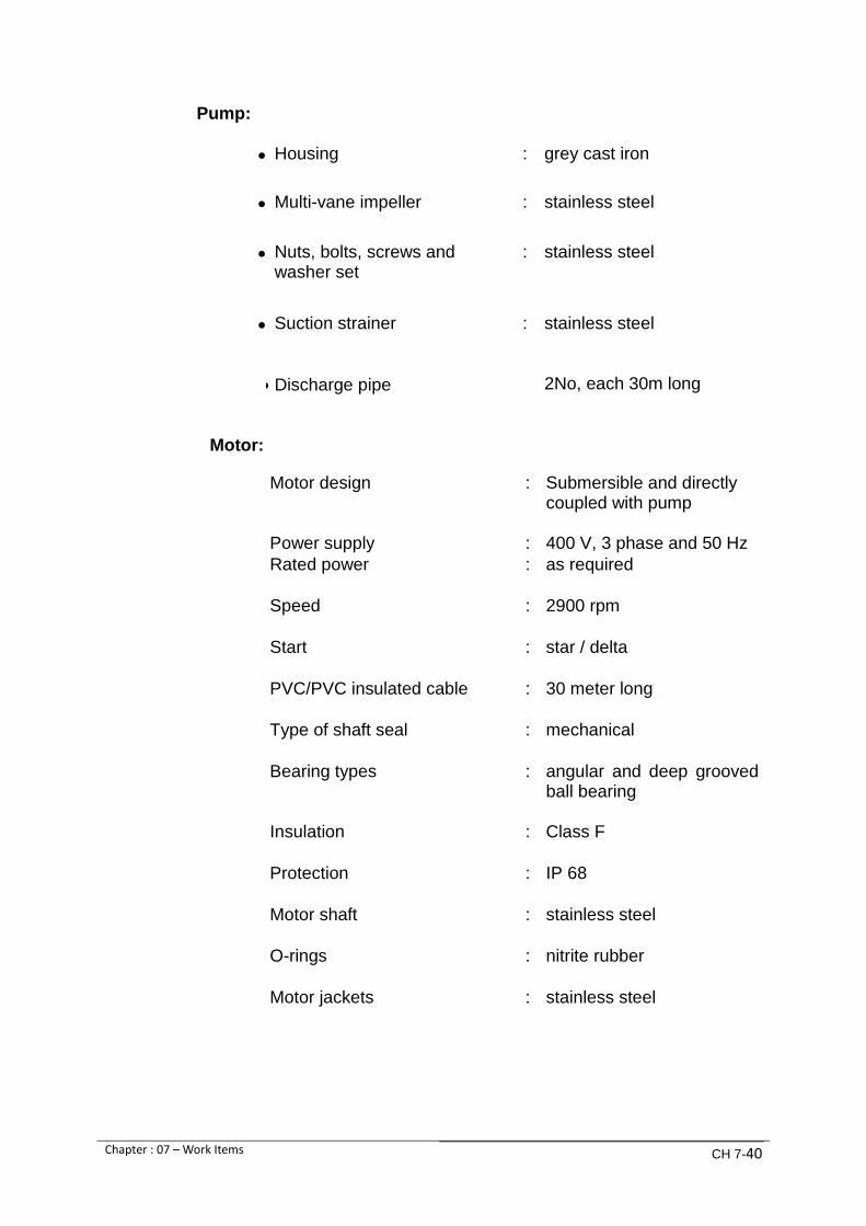
Chapter : 07 – Work Items CH 7-40
Pump:
Housing : grey cast iron
Multi-vane impeller : stainless steel
Nuts, bolts, screws and washer set
: stainless steel
Suction strainer
Discharge pipe
: stainless steel 2No, each 30m long
Motor:
Motor design : Submersible and directly coupled with pump
Power supply : 400 V, 3 phase and 50 Hz
Rated power : as required
Speed : 2900 rpm
Start : star / delta
PVC/PVC insulated cable : 30 meter long
Type of shaft seal : mechanical
Bearing types : angular and deep grooved ball bearing
Insulation : Class F
Protection : IP 68
Motor shaft : stainless steel
O-rings : nitrite rubber
Motor jackets : stainless steel

Chapter : 07 – Work Items CH 7-41
7.5.6 Work Item No.35: Security system
Pumping Station is a sensitive area and unwanted / undesired movements are required to be monitored. Therefore, a security system is required, comprising CCTV cameras, recording system, display units and other affiliated material/equipments. The Station perimeter and inside building is required to be monitored on 24/7 basis with Digital CCTV cameras having Infra Red & motion detection facility for Day/Night recording. A separate storage device with minimum 30 days recording backup capacity is to be provided. The outdoor camera should have IP65 protection housing. Contractor will also propose archiving system for CCTV recordings with all required hardware/software.
Minimum requirements shall be as under:
Item No. Description Qty.
1
Digital CCTV Camera
Max Video Resolution (Pixel) 1,280x960
True Day/Night
Power Source (PoE+)
** All outdoor cameras will have speed doom and
audio with supported codec and housed in IP65
box
18
2 Recording System (NVR)
1
3 LCD 21”
3
4 PTZ Controller 1
5
Providing, Installing and fixing at any height CCTV
cameras with cables, connectors and power
supply, including poles complete in all respect. 1
7.5.7 Work Item No.36: Lighting arrangement on boundary wall Perimeter lighting to illuminate the boundary wall approx: 1300 meter and its surroundings shall be included. Narrow beam flood lights with high pressure Sodium lamps shall be used. Design calculations shall be submitted for approval of the Employer.

Chapter : 07 – Work Items CH 7-42
7.5.8 Work Item No.37: Equipment spare parts
Priced lists of recommended spare parts for five years as provided in Clause 1.24 of the Specification, Volume-II.
The spare parts cost shall not be included in the total Tender Cost but given separately and will be given due weightage in the evaluation of the Tender. Separate order for supply shall be placed by the Employer on the basis of approved items of spare parts and charged to the provisional sum. Prices of spare parts given in Annexure-B may also be included in the recommended list.
7.5.9 Work Item No.38: Special tools and test equipment
Priced list of tools and test equipment as provided in Clause 1.25 of the Specification, Volume-II. The cost of tools and test equipment shall not be included in the total Tender Cost but given separately and will be given due weightage while evaluating the Tender Separate order for supply shall be given by the Employer on the basis of approved items and charged to the provisional sum. Prices of tools given in Annexure-c may also be included in the recommended list.
7.5.10 Provisional Sums
Payment work for Items 39, 40 and unforeseen will be made against works and services of Rs. 30,000,000 (Rupees Thirty Million only)
EMPLOYER’S REQUIRMENT FOR
MECHANICAL & ELECTRICAL WORKS
CHAPTER 08
SCHEDULE OF GUARANTEES

CHAPTER 08
SCHEDULE OF GUARANTEES
TABLE OF CONTENTS
8.1. Schedule of Guarantees ........................................................................................................... 1
8.2. Manual coarse screen .............................................................................................................. 2
8.3. Chain hauled rakes screen ....................................................................................................... 2
8.4. Central flow band screen ......................................................................................................... 3
8.5. Rake screen debris skips .......................................................................................................... 4
8.6. Band screen debris skips .......................................................................................................... 5
8.7. Dhabeji pumps: ........................................................................................................................ 5
8.8. Pumps motors: ......................................................................................................................... 6
8.9. Flexible shaft: ........................................................................................................................... 8
8.10. Pipe Work: ................................................................................................................................ 8
8.11. Electric Overhead Gantry Crane:.............................................................................................. 9
8.12. Flow meter: .............................................................................................................................. 9
8.13. Submersible pumps:............................................................................................................... 10
8.14. Butterfly valves (All applications):.......................................................................................... 10
8.15. Non return valves: .................................................................................................................. 11
8.16. Hydraulic damping devices: ................................................................................................... 12
8.17. Flexible Slip out Joints (all applications): ............................................................................... 12
8.18. Pressure Relief Valves ............................................................................................................ 12
8.19. Penstock ................................................................................................................................. 13
8.20. Main 11 KV Incoming switch board ....................................................................................... 14
8.21. 11 KV transformer outgoing ................................................................................................... 16
8.22. 11 KV pump motor outgoings ................................................................................................ 16
8.23. Transformers .......................................................................................................................... 17
8.24. Cables ..................................................................................................................................... 18
8.25. Control and Instruments ........................................................................................................ 18
8.26. Earthing Equipment ............................................................................................................... 18
8.27. LV distribution switchboard for utilities ................................................................................ 19

8.28. LV distribution switchboard for pump house ........................................................................ 19
8.29. Operating requirements ........................................................................................................ 20

Chapter : 08 - SCHEDULE OF GUARANTEES CH-8-1
CHAPTER 08
SCHEDULE OF GUARANTEES
8.1. Schedule of Guarantees
1. The Contractor shall guarantee that the plant and equipment supplied under the Contract shall be new and in accordance with the Tender including variations/deviations, if any, jointly agreed by the Employer and the Contractor and shall be free from defects and poor workmanship. In the event of any defect or failure in the performance of any component of the Plant or part thereof within the guaranteed period specified in the Tender, the same shall be replaced or repaired by the Contractor to the satisfaction of the Employer free of charge, normal wear and tear accepted.
2. The Contractor shall further guarantee that the performance data given by
him in the Schedule of Guarantees shall be complied with by him.
In the event of guaranteed performance not being attained, the Contractor shall improve the same to the guaranteed level at his own expense within a reasonable time to the satisfaction of the Employer.
3. Parts which as a result of material or manufacturing defects become unusable
or the usefulness of which is appreciably decreased, shall he repaired satisfactorily or replaced free of charge by the Contractor on intimation of such defects by the Employer in writing.
Defective parts shall be property of the Contractor.

Chapter : 08 - SCHEDULE OF GUARANTEES CH-8-2
SCHEDULE OF GUARANTEES
S.No. Description Unit Tenderer’s Guarantees
1
2
8.2. Manual coarse screen Manufacturer Country of origin Type Bar screen height Bar screen width Bar size Bar spacing Velocity through bars at max flow Head loss through bars at maximum flow Skip Size Material of construction Frames Rake assembly Rake tines Hand rakes 8.3. Chain hauled rakes screen Manufacturer Country of origin Type Bar screen height Bar screen width
m
m
mm x mm
mm
m/sec.
mm
m
m

Chapter : 08 - SCHEDULE OF GUARANTEES CH-8-3
S.No. Description Unit Tenderer’s Guarantees
3
Bar size Bar spacing Screen capacity max. Velocity through bars at max flow Head loss through bars at maximum flow Discharge height above deck Screen raking speed Motor size Motor speed Motor protection Material of construction Side frames Roller tracks Head shaft Chain shaft Main chain links Main chain pins Main chain bushes Main chain rollers Rakes assembly Rakes tines 8.4. Central flow band screen Manufacturer Country of origin Type Mesh opening size Effective screening width
mm
mm
m3/sec
m/sec.
mm
mm
m/min
kW
rpm
IP
mm
m
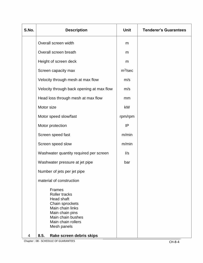
Chapter : 08 - SCHEDULE OF GUARANTEES CH-8-4
S.No. Description Unit Tenderer’s Guarantees
4
Overall screen width Overall screen breath Height of screen deck Screen capacity max Velocity through mesh at max flow Velocity through back opening at max flow Head loss through mesh at max flow Motor size Motor speed slow/fast Motor protection Screen speed fast Screen speed slow Washwater quantity required per screen Washwater pressure at jet pipe Number of jets per jet pipe material of construction Frames Roller tracks Head shaft Chain sprockets Main chain links Main chain pins Main chain bushes Main chain rollers Mesh panels 8.5. Rake screen debris skips
m
m
m
m3/sec
m/s
m/s
mm
kW
rpm/rpm
IP
m/min
m/min
I/s
bar

Chapter : 08 - SCHEDULE OF GUARANTEES CH-8-5
S.No. Description Unit Tenderer’s Guarantees
5
6
Length Breath Height Weight empty Max. Carrying Capacity Material of Construction 8.6. Band screen debris skips Length Breath Height Weight empty Max. carrying capacity Material of Construction 8.7. Dhabeji pumps: Manufacturer Country of Origin Model Total head at duty point Flow at duty point Efficiency at duty point NPSH required at duty point Runout condition flow
m
m
m
Kg
Kg
m
m
m
Kg
Kg
m
m3/s
%
m
m3/s

Chapter : 08 - SCHEDULE OF GUARANTEES CH-8-6
S.No. Description Unit Tenderer’s Guarantees
7
Runout condition head Power Consumption at duty point Max. power consumption over pumping range Speed Suction flange diameter Discharge flange diameter Impeller diameter duty / maximum Casing material Impeller material Shaft material Casting wear ring material Impeller wear ring material Shaft sleeve material at gland Rating Test pressure Weight Moment of inertia Bottom bearing material Bottom bearing type 8.8. Pumps motors: Manufacturer
m
KW
KW
rpm
mm
mm
bar
bar
kg
kg-m2

Chapter : 08 - SCHEDULE OF GUARANTEES CH-8-7
S.No. Description Unit Tenderer’s Guarantees
Country of Origin Model Voltage Rating Full load current Duty point current Starting current Efficiency full load Efficiency 3/4 load Efficiency 1/2 load Power factor full load Power factor 3/4 load Power factor 1/2 load Insulation class Enclosure protection Noise level at duty point dB (A) at 1m Bearing type Moment of inertia Run up time Permitted numbers of start per hour Weight
KV
KW
A
A
A
%
%
%
IP
dB(A)
kg-m2
second
kg

Chapter : 08 - SCHEDULE OF GUARANTEES CH-8-8
S.No. Description Unit Tenderer’s Guarantees
8
9
method of cooling Non – reversing arrangement 8.9. Flexible shaft: Manufacturer Country of origin type Diameter of shaft Length of shaft Material of construction Type of bearing upper / lower Type of intermediate bearings Numbers of intermediate bearings Guard system 8.10. Pipe Work: Manufacturer Country of origin Material Thickness of plate (1800mm diameter) Thickness of plate (800 mm diameter) Thickness of plate (450 mm diameter) Thickness of plate (300 mm diameter) Rating
mm
m
mm
mm
mm
mm
bar

Chapter : 08 - SCHEDULE OF GUARANTEES CH-8-9
S.No. Description Unit Tenderer’s Guarantees
10
11
Test Pressure Internal coating External finishing priming External finishing top coat 8.11. Electric Overhead Gantry Crane: Manufacturer Country of origin Type Lifting capacity Voltage Hoist speed high / low Motor size Motor speed Travel speed Motor size Motor speed Gantry crane speed 8.12. Flow meter: Manufacturer Country of origin Type
bar
tonne
V
m/min
KW
rpm
m/min
KW
rpm
m/min

Chapter : 08 - SCHEDULE OF GUARANTEES CH-8-10
S.No. Description Unit Tenderer’s Guarantees
12
13
Model Pressure rating Diameter Flange rating Body material Internal lining External coating Flow range Control signal 8.13. Submersible pumps: Manufacturer Country of origin Type Model Duty flow Duty head Motor rating Motor protection Speed Overall efficiency at duty point 8.14. Butterfly valves (All applications):
bar
mm
PN
m3/s
mA
l/s
m
KW
IP
Rpm
%

Chapter : 08 - SCHEDULE OF GUARANTEES CH-8-11
S.No. Description Unit Tenderer’s Guarantees
14
Manufacturer Country of origin Type Working pressure Test pressure Size of bypass Material of construction Body Shaft Seals Rating 8.15. Non return valves: Manufacturer Country of origin Type Diameter Working pressure Test pressure Material of construction Body Disc Body seal Disc facing ring Disc Body seal
bar
bar
mm
PN
mm
bar
bar

Chapter : 08 - SCHEDULE OF GUARANTEES CH-8-12
S.No. Description Unit Tenderer’s Guarantees
15
16
17
Seal Valve shaft Bushes Lever arm Lever weight 8.16. Hydraulic damping devices: Manufacturer Country of origin Type Maximum closing time Minimum closing time Designed closing time Material of construction Body Piston 8.17. Flexible Slip out Joints (all
applications): Manufacturer Country of origin Type Packing material Working pressure Test pressure 8.18. Pressure Relief Valves Manufacturer
sec
sec
sec
bar
bar
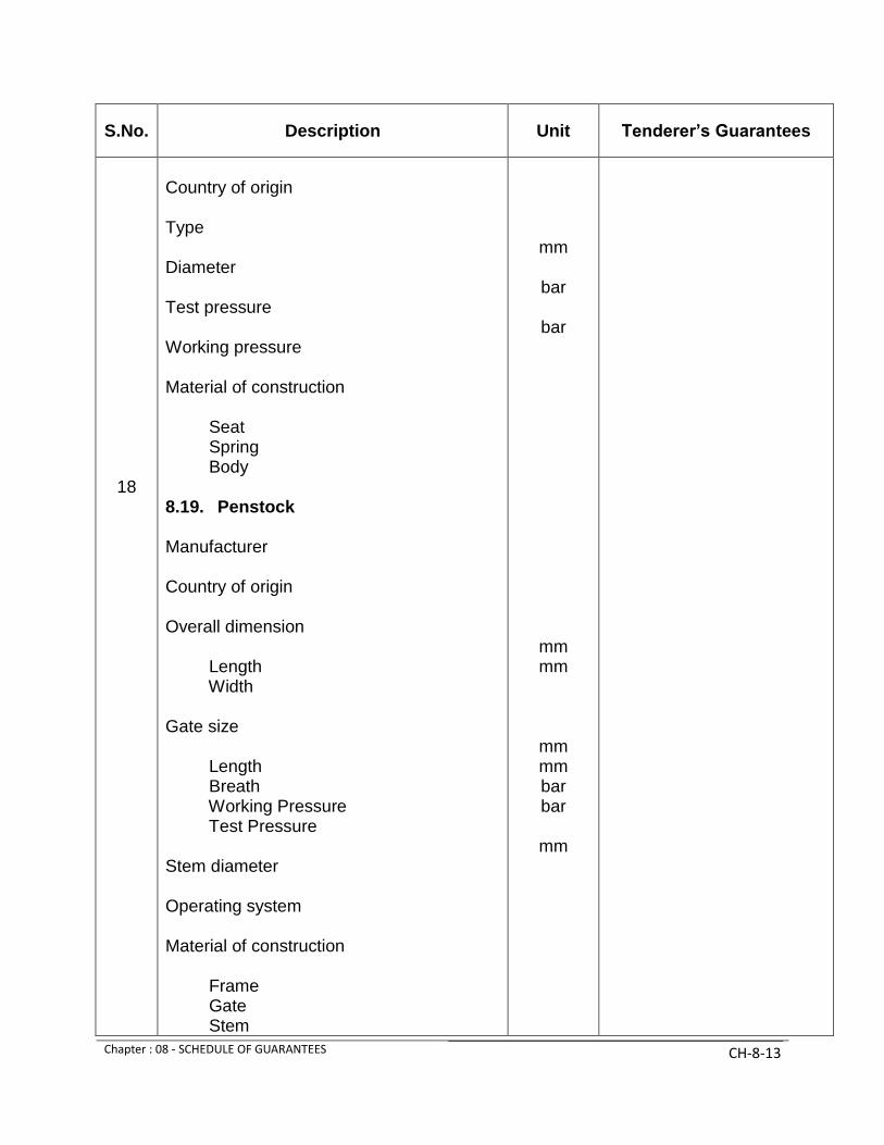
Chapter : 08 - SCHEDULE OF GUARANTEES CH-8-13
S.No. Description Unit Tenderer’s Guarantees
18
Country of origin Type Diameter Test pressure Working pressure Material of construction Seat Spring Body 8.19. Penstock Manufacturer Country of origin Overall dimension Length Width Gate size Length Breath Working Pressure Test Pressure Stem diameter Operating system Material of construction Frame Gate Stem
mm
bar
bar
mm mm
mm mm bar bar
mm

Chapter : 08 - SCHEDULE OF GUARANTEES CH-8-14
S.No. Description Unit Tenderer’s Guarantees
19
Seats 8.20. Main 11 KV Incoming switch
board Manufacturer Country of origin Type Type Nr Rated normal service voltage Number of mases Frequency Overall dimensions of switchboard Height Length Width Weight Weight and dimensions per panel Height Length Depth Weight(total) Weight of moving portion Minimum distance required for withdrawal of moving portion Minimum height for removal of voltage transformer
vacuum
KV
Hz
mm mm mm kg
mm mm mm kg kg
mm
mm

Chapter : 08 - SCHEDULE OF GUARANTEES CH-8-15
S.No. Description Unit Tenderer’s Guarantees
Maximum shock load imposed on foundations when operating under fault conditions. (State whether tension or compression) Switchgear and bus-bars Rated bus-bar current Maximum temperature rise at rated bus-bar current above 45oC ambient Bus-bar type test report reference Short time withstand current of switchgear & bus-bar
a) One second b) Three second
Making capacity Constructional features Is an external series break incorporated in breaker Method of closing Method of tripping Closing solenoid coil current and duration at rated voltage Closing solenoid coil rated voltage Trip coil current and duration at rated voltage Trip coil rated voltage Minimum dc voltage required for
KN
A
oC
rms kA rms kA
peak kA
A ms
V dc
A
ms
V dc
V dc

Chapter : 08 - SCHEDULE OF GUARANTEES CH-8-16
S.No. Description Unit Tenderer’s Guarantees
20
21
successful closing at make rating Rating of heaters for circuit breakers 8.21. 11 KV transformer outgoing Manufacturer Country of origin Type Type Nr. Rated nominal service voltage Number of phases Frequency Overall dimensions of switchboard Height Length Width Weight Minimum distance required for withdrawal / removal of switchboard components. Bus- bars Rated bus bar current Maximum temperature rise at rated bus bar current above 45oC ambient Bus bar fault rating For 8.22. 11 KV pump motor outgoings
W
vacuum
kV
Hz
mm mm mm kg
mm
A
oC
kA seconds

Chapter : 08 - SCHEDULE OF GUARANTEES CH-8-17
S.No. Description Unit Tenderer’s Guarantees
22
Manufacturer Country of origin Type Type Nr. Rated nominal service voltage Number of phases Frequency Overall dimensions of switchboard Height Length Width Weight Minimum distance required for withdrawal/ removal of switchboard components Bus- bars Rated bus bar current Maximum temperature rise at rated bus bar current above 45oC ambient Bus bar fault rating For 8.23. Transformers Manufacturer Country of origin Rated Voltage
vacuum
kV
Hz
mm mm mm kg
mm
A
oC
kA seconds
kV/V
kVA

Chapter : 08 - SCHEDULE OF GUARANTEES CH-8-18
S.No. Description Unit Tenderer’s Guarantees
23
24
25
Rating Height Length Width Weight Weight (without – oil) Fault rating for Protection 8.24. Cables 11 KV Manufacturer Type 400/230 v Manufacturer Type 8.25. Control and Instruments Manufacturer Type 8.26. Earthing Equipment Manufacturer Earth electrodes Inspection covers Cabling Copper earth bar size
mm mm mm kg kg
kA seconds
IP
Nos.

Chapter : 08 - SCHEDULE OF GUARANTEES CH-8-19
S.No. Description Unit Tenderer’s Guarantees
26
27
Thermionic welding material 8.27. LV distribution switchboard for
utilities Manufacturer Bus bar continuous rating Bus bar fault rating for Protection Incoming MCCB Manufacturer Rating Fault rating for 8.28. LV distribution switchboard for
pump house Manufacturer Bus bar continuous rating Bus bar fault rating for Incoming ACB manufacturer Rating Fault rating for ACB manufacturer ACB dimensions
A
kA seconds
IP
A
kA seconds
A
kA seconds
A
kA seconds
mm mm mm

Chapter : 08 - SCHEDULE OF GUARANTEES CH-8-20
S.No. Description Unit Tenderer’s Guarantees
28
Height Length Width Weight MCB manufacturer Contactor manufacturer Dimensions Height Length Width Weight 8.29. Operating requirements The following items are to be completed in order to obtain an estimate of operating cost: Electrical loads:
1) Total connected load 2) Maximum running load 3) Average running load 4) Guaranteed average power
consumption
kg
mm mm mm kg
KW KW
KWh/day
KWh/day

KKAARRAACCHHII WWAATTEERR && SSEEWWEERRAAGGEE BBOOAARRDD
TTAABBLLEE OOFF CCOONNTTEENNTTSS
VVOOLLUUMMEE--IIII ((11))
EEMMPPLLOOYYEERR’’SS RREEQQUUIIRREEMMEENNTTSS
FFOORR
MMEECCHHAANNIICCAALL && EELLEECCTTRRIICCAALL WWOORRKKSS
CChhaapptteerr--0011:: GGeenneerraall RReeqquuiirreemmeennttss
CChhaapptteerr--0022:: MMeecchhaanniiccaall && EElleeccttrriiccaall PPllaannttss
CChhaapptteerr--0033:: GGeenneerraall TTeessttiinngg,, IInnssppeeccttiioonn,, CCoommmmiissssiioonniinngg aanndd TTrraaiinniinngg
CChhaapptteerr--0044:: MMeecchhaanniiccaall WWoorrkkss
CChhaapptteerr--0055:: EElleeccttrriiccaall WWoorrkkss
CChhaapptteerr--0066:: PPaaiinnttiinngg aanndd PPrrootteeccttiioonn
CChhaapptteerr--0077:: WWoorrkk IItteemmss
CChhaapptteerr--0088:: SScchheedduullee ooff GGuuaarraanntteeeess
VVOOLLUUMMEE--IIII ((22))
EEMMPPLLOOYYEERR’’SS RREEQQUUIIRREEMMEENNTTSS
FFOORR
CCIIVVIILL WWOORRKKSS
CChhaapptteerr 0099:: CCiivviill WWoorrkkss -- SSccooppee ooff WWoorrkk
CChhaapptteerr 1100:: CCiivviill WWoorrkkss -- EEmmppllooyyeerrss RReeqquuiirreemmeennttss

KKAARRAACCHHII WWAATTEERR && SSEEWWEERRAAGGEE BBOOAARRDD
TTAABBLLEE OOFF CCOONNTTEENNTTSS
VVOOLLUUMMEE--IIII ((22))
EEMMPPLLOOYYEERR’’SS RREEQQUUIIRREEMMEENNTTSS
FFOORR
CCIIVVIILL WWOORRKKSS
CChhaapptteerr 0099:: CCiivviill WWoorrkkss -- SSccooppee ooff WWoorrkk
CChhaapptteerr 1100:: CCiivviill WWoorrkkss -- EEmmppllooyyeerrss RReeqquuiirreemmeennttss

EMPLOYER’S REQUIRMENT FOR CIVIL WORKS
CIVIL WORKS - SCOPE OF WORK

CHAPTER 09 CIVIL WORKS - SCOPE OF WORK
TABLE OF CONTENTS
9.1 General introduction ..................................................................................................... 1 9.2 General Description of the Project ................................................................................ 2 9.3 Design and planning of the works ................................................................................ 3 9.4 General description of Civil Works (scope of work) .................................................... 4 9.5 Construction of the permanent works ........................................................................... 4 9.6 Pump house at basement level and suction channel ..................................................... 6 9.7 Chambers ...................................................................................................................... 6 9.8 K-Electric sub-station ................................................................................................... 6 9.9 External site drainage .................................................................................................... 6 9.10 External sewerage ......................................................................................................... 6 9.11 Access road and parking areas: ..................................................................................... 6 9.12 Site development: ......................................................................................................... 6 9.13 Provision of camp and office facilities ......................................................................... 7 9.14 Temporary site installations .......................................................................................... 7 9.15 Temporary facilities to be handed over to the Employer .............................................. 7 9.16 Power and water supply for construction ...................................................................... 7 9.17 Health and Safety .......................................................................................................... 7 9.18 Quality assurance / quality control ............................................................................... 7 9.19 Environmental Compliance .......................................................................................... 7 9.20 Training Programme ..................................................................................................... 8 9.21 Setting out of works ...................................................................................................... 8

Chapter : 09 – Scope of Work CH-9-1
CHAPTER 9 CIVIL WORKS - SCOPE OF WORK
9.1 General introduction
This section lays out the requirements of the Employer regarding the Civil Works for the project. The final arrangement of the works shall be developed and construction by the Contractor to best exploit the local physical conditions while maintaining the fitness for purpose inherent in the outline requirements. Nonetheless contractor is responsible to substantiate these requirements to ensure complete functional performance of Pumping Station and Fulfillment of his obligations under this Contract. The Employer’s Requirements have been prepared in consideration of the Conditions of Contract for EPC/ Turnkey Project. The Contractor will be responsible for all aspects of design and construction of the Project in accordance with the Employer’s Requirements, design criteria and specifications furnished herein, and in accordance with additional and supplementary design criteria and specifications prepared by the Contractor and accepted by the Employer.
The scope of the Works will include, but not limited to:
1. Preparation of all detailed design criteria, design analysis, design
calculations, design detailing, construction specification, detailed construction drawings and quality control procedures, necessary for the complete construction of the project together with O&M Manuals, and as built record drawings.
2. Additional Site Investigations, survey as necessary to develop a
fully functional design for Pumping Station.
3. The drafting of and adherence to a construction schedule sufficient to meet the requirements of the Project.
Major Civil Works Include:
a. Screen chamber b. Suction well c. Pump house building with associated facilities d. Flow meter chamber and valve Chambers e. K - Electric Sub – station f. Car park, road and walkways
External development works including landscaping
a. All temporary works required to construct the Project, including offices for the Employer and laboratory buildings complete with furnishing and equipment’s.
b. Provision and maintenance of vehicles for the Employer’s staff.

Chapter : 09 – Scope of Work CH-9-2
c. Conceptual Drawings of the Project are given in Volume-III of this Tender Document.
9.2 General Description of the Project
Site location The Project is located in general in the vicinity of Pump Station Buildings completed at Dhabeji under different projects and minimum 9.0 meter away from Pump House No. 2 and minimum 2.0 meter distance from Pump House No.3, in particular. The conceptual Drawings are attached in Volume III showing the location of the project and guide line plan.
Site access The Access to the site of the project is through Paved Road from National Highway to Dhabeji Pump Station. Climatic data The Contactor shall take account of the climatic conditions at the Site of the Works. The following information is provided as a guide to the climatic condition likely to be encountered on the site to assist the Contractor, but this shall not relieve him of his responsibility under the Contract.
a. Monthly average temperatures:
(1) Maximum 35 oC (2) Minimum 18 oC
b. External temperatures
47 oC in June 2 oC in January
c. Annual average rainfall 192 mm per year, the majority falling in the monsoon months of July and August. On average there are 10 rainy days per year. Storm intensities can be high with storm totals reaching 200mm, with normal durations of 1 to 2 days.
d. Monthly Average Relative Humidity
(1) Maximum = 90% (2) Minimum = 40%
The climatic data given above are based on limited records and their accuracy cannot therefore be guaranteed.

Chapter : 09 – Scope of Work CH-9-3
9.3 Design and planning of the works
General The Contractor shall perform engineering services pertinent to planning and design of the work in accordance with accepted Standards. In addition, the Contractor shall establish & submit to Employer a Quality Control / Quality Assurance program to verify that the Work performed by the Contractor is in accordance with & fully meets the requirement of the Contract. Design All Design shall be performed in accordance with the requirement given in the following Section, Basic Design Criteria. The Design of the Works shall be performed during a Detailed Design phase. The Design responsibility of the Contractor shall be as follows:
a. The Contractor shall carry out the Detailed Design and construction drawings of the Permanent Works to be performed under this Contract and the site investigations deemed necessary for the Design.
b. The Contactor shall prepare the Detailed Design and construction
drawings of necessary Temporary and Permanent Works to be performed under this Contract
c. The Contractor shall prepare Construction Method Statements
and an Implementation Plan, and d. The Contractor shall prepare the detailed design and Shop
Drawings of the components of the project and equipment to be installed under this Contract.
The activities to be performed under the Detailed Design are outlined
below: a. Geological and geotechnical investigations; b. Topographic investigations; c. Expansion and clarification of design criteria and parameters; d. Summary of all tests and investigation planned to be carried out in
connection with the Detailed Design; e. Design Memorandum; f. Detailed Design; g. Construction Drawings; h. Civil Shop Drawings; i. Manufacture’s Shop Drawings to the extent necessary for
Employer’s design review and operation and maintenance; a. Plan of the methods of achieving the Construction Requirements; b. Report on construction methods to be used for all major works; c. Procurement plan for major equipment; d. Layout drawings for all temporary works; e. Principal items of construction planned to be used;

Chapter : 09 – Scope of Work CH-9-4
f. Detailed information of site offices and camp facilities; g. Quality Control and Quality Assurance procedures for
Construction; h. Plan for disposal of spoil material; i. Environmental Management Plan Including measures for
rehabilitation of work areas; j. Construction Security, Health and Safety plans; and k. Basic outlines of the Operation and Maintenance Manuals, and
proposed Training Program. For each structure of the project, the Contractor shall prepare Detailed Design documentation to include as a minimum:
a. Description of each structure b. Design criteria c. Review of assumptions and design procedures, adopted design
criteria, loads and load cases used d. Codes and books referred e. Short description of each method of analysis, computer programs
used etc. f. Structure analysis by using latest versions of SAP – 2000, ETAB,
SAFE, STAAD or any other. g. Calculations and principal results of the detailed design analyses h. Detailed design drawings and specifications for construction and i. Civil and manufacture’s shop drawings.
9.4 General description of Civil Works (scope of work)
The principal elements of the Civil Works are: a. Provision of Materials; b. Provision of Services; c. Provision of Temporary Works; d. Construction of Permanent Works; e. Demobilization, site rehabilitation, clean up mitigation in
accordance with national and local regulations of all environment impacts form construction, and disposal of excess materials and debris.
The descriptions given in the document are outline descriptions only. Such descriptions do not include or give full details of all materials or other items to be supplied or all works and services to be executed by the Contractor in order to fulfill its obligations under the Contract.
9.5 Construction of the permanent works General The Permanent Works to be performed by the Contractor are described below;

Chapter : 09 – Scope of Work CH-9-5
Inlet works The inlet and screen chambers and suction well shall be R.C.C structure having fair face finish. The design shall conform to the standard codes and requirements as given out under the relevant items.
Pump House at Ground floor level:
(1) The ground floor shall have the following facilities:
Motor hall PLC/SCADA control room Transformer room Panel room Toilets
(2) The first floor shall have the following facilities
Office / Conference room Kitchen Control room Battery room Store room Toilets
(3) R.C.C columns shall be fair face finish and provided with corbel
for gentry crane.
(4) R.C.C floor / slab with openings for lowering the pumps etc. shall have removable covers of aluminum alloy checquered plate of non-slip pattern min. 4.5 mm thick.
(5) Cable trenches / pits shall have fair face finish and provided with aluminum alloy checquered plate steel plate covers/flooring of non-slip pattern. The plate shall be minimum 4.5 mm thick.
(6) The height of the building shall be enough to accommodate the designed motors and pumps and overhead crane.
(7) Finish to the exterior surface of the building shall be as detailed under relevant clauses & as directed by the Engineer.
(8) Plinth protection shall be provided around the building with a semi circular cement concrete lined drain.
(9) Sun – shades shall be provided to the Windows and Ventilators to match external architecture.
(10) Windows and ventilators shall be provided with galvanized steel wire mesh of 20 mm square.

Chapter : 09 – Scope of Work CH-9-6
(11) Windows shall be sliding type
(12) Windows in the office will be provided with double glazing
(13) Windows in the motor hall shall be provided with mechanism for opening
(14) Proper sewerage and drainage arrangements from the building shall be provided. HDPE -100 Pipe shall be used.
(15) Plumbing works shall be complete using HDPE-100 pipe and fixtures of the best quality available preferably Masters.
9.6 Pump house at basement level and suction channel The basement shall be an R.C.C structure having fair face finish. The design shall conform to the standard codes and requirement as given out under the relevant clauses.
9.7 Chambers The chamber shall be R.C.C. fair face finish concrete and chamfered edges. The chamber shall be minimum 300 mm above the finished ground level. Where the chambers are covered, the covers shall be of heavy duty galvanized iron covers and frame.
9.8 K-Electric sub-station The building shall be as per approved drawing of the K-Electric.
9.9 External site drainage Site drainage shall be properly designed and provided with HDPE-100 drainage pipes road crossings and precast covers wherever required.
9.10 External sewerage External sewerage shall be designed and provided with HDPE -100 pipes and C.C manholes of standard size into R.C.C septic tank and soak away as required.
9.11 Access road and parking areas: Existing road / walkways where dismantled shall be restored to its original condition. New roads and parking areas shall be made in cement concrete and should be of adequate dimensions. Cross drainage structures shall be RCC type & to be provided at suitable location along the alignment and elsewhere deemed necessary.
9.12 Site development: Site development around the pump house and ancillary structure including culverts, leveling, grading, landscaping and grass & shrubs areas shall be minimum 2000 sq. meters as per approval of the Employer.

Chapter : 09 – Scope of Work CH-9-7
9.13 Provision of camp and office facilities General Provision of Office and Camp facilities shall be made by the Contractor. The Contractor shall design, install, operate, provide all consumable items, spares, replacements and fuel and shall maintain throughout the execution of the work office facilities required for the Works.
9.14 Temporary site installations The Contractor shall design, install and maintain throughout the execution of the Works all temporary facilities required for the work. On completion of the Project, the Contractor shall remove all temporary facilities, including their foundations that are not handed over to the Employer, and restore the area.
9.15 Temporary facilities to be handed over to the Employer At the expiry of time of completion, selected temporary facilities or part of it, if and as described in Employer’s Requirements, shall be handed over to the Employer in good, and serviceable conditions, so that these can be utilized by the Employer without any further treatment, renovation or repair.
9.16 Power and water supply for construction The Contractor shall be responsible for the design and provision of temporary power supply for site during construction of the works. The Contractor shall be responsible for the supply of potable water as well as disposal and treatment of wastewater and reuse. If water is supplied by the Employer, the cost thereof shall be deducted from contractor bills at the rate fixed by the Employer and which will be the commercial tariff.
9.17 Health and Safety
The Contractor shall be under an obligation to take all reasonable safety measures in relation to the type of services undertaken and shall conduct itself and all personnel assigned to the Work and perform the Work in such a way as to comply at all times with its obligation and duties under laws, regulation, rules, order and other enactments in force from time to time relating to health and safety matters, including the Employer’s safety requirements.
9.18 Quality assurance / quality control
The Contractor will instigate a QA/QC programmed in accordance with the relevant Clause of the EPC Contract and section 2 of this volume.
9.19 Environmental Compliance
Reference is made to the environmental requirements given in:
a. The law and Regulation of Government of Pakistan arid Government of Sindh.
b. Employer’s Requirements for Environmental Protection given in
this Volume.

Chapter : 09 – Scope of Work CH-9-8
c. Sub-Clauses 4.18 [Protection of environment], 4.22 [Security of the Site], 4.23 [Contractors Operation at Site], 4.24 [Fossils], 6.6 [facilities for staff and Labour], 6.7 [Health and Safety], 7.3 [Inspection], 14.5 [Plant and Material Intended for the Works], 16.3 [Cessation of Work and Removal of Contractor Equipment] of General Condition of Contract and any other clause or sub-clause having any relevance to Environment.
d. Local traditions and customs of Sindh.
e. The Contractor shall within one month of receipt of Notice to
Proceed, appoint an Environmental Inspector for the Works, whose broad responsibilities are to guide the construction personnel on environmental matters, to communicate and to make liaison with the Employer, Government of Sindh and local elders.
f. The Contractor shall provide Environment Management Plan of
the Site as defined in this Volume.
9.20 Training Programme The Contractor shall provide a training program in operation and maintenance for the Employer’s O&M personnel generally to meet the requirements stated in Volume II of Bid Documents.
9.21 Setting out of works Setting out data such as BENCH MARK, DATUMS and original setting out points shall be provided by the Employer.

EMPLOYER’S REQUIRMENT FOR
CIVIL WORKS
CHAPTER 10 CIVIL WORKS - EMPLOYER’S REQUIREMENTS

CHAPTER 10 CIVIL WORKS - EMPLOYER’S REQUIREMENTS
TABLE OF CONTENTS
10.1 Scope of Work ............................................................................................................ 1 10.2 Contractor’s responsibilities ...................................................................................... 1 10.3 Engineering and design ............................................................................................ 2 10.4 Basic design criteria and applicable codes ............................................................ 2 10.4.1 Design load & load combinations ............................................................................ 3 10.5 Units of measurement ............................................................................................... 4 10.6 Economic life of works ............................................................................................... 4 10.7 Bid submissions .......................................................................................................... 4 10.8 Detailed design submission ...................................................................................... 5 10.9 Construction and construction management ......................................................... 8 10.10 Procurement................................................................................................................ 8 10.11 Standards of design and works ................................................................................ 9 10.12 Testing ......................................................................................................................... 9 10.13 Design control ............................................................................................................. 9 10.14 Contractor’s tests ..................................................................................................... 10 10.15 General description of Civil Works (scope of work) ............................................ 10 10.16 Construction of the permanent works ................................................................... 10 10.17 General ...................................................................................................................... 10 10.18 Inlet works ................................................................................................................. 11 10.19 Pump House at Ground floor level: ....................................................................... 11 10.20 Pump house at basement level and suction channel ......................................... 12 10.21 Chambers: ................................................................................................................. 12 10.22 KESC sub-station: .................................................................................................... 12 10.23 External site drainage: ............................................................................................. 12 10.24 External sewerage ................................................................................................... 12 10.25 Access road and parking areas: ............................................................................ 12 10.26 Site development: .................................................................................................... 12 10.27 Civil Works Requirements (General)..................................................................... 13 10.28 Excavation ................................................................................................................. 13 10.29 Clearing Site.............................................................................................................. 13 10.30 Exploration of Borrow Areas and Quarries ........................................................... 13 10.31 Excavation in Soil ..................................................................................................... 14 10.32 Shoring of Existing Structures ................................................................................ 14 10.33 Slips, fall and Excess Excavation .......................................................................... 14 10.34 Dewatering ................................................................................................................ 14 10.35 Excavation of Foundation ....................................................................................... 15 10.36 Disposal of Surplus Material ................................................................................... 15 10.37 Preparation of Foundations .................................................................................... 15 10.38 Concrete and Reinforcement ................................................................................. 15 10.39 Materials .................................................................................................................... 16 10.40 Aggregates ................................................................................................................ 17 10.41 Batching and Mixing ................................................................................................ 18 10.42 Construction Joint Treatment ................................................................................. 20 10.43 Water Stops .............................................................................................................. 20 10.44 Forms 21 10.45 Curing and Protection .............................................................................................. 21

10.46 Finishes and Finishing ............................................................................................. 21 10.47 Steel Reinforcement ................................................................................................ 22 10.48 Fill 23 10.49 Architectural Finishing ............................................................................................. 24 10.50 Security, health and safety ..................................................................................... 32 10.51 Furniture and equipment for the office in the Pump House ............................... 32 10.52 Surveying Instruments and Surveyors .................................................................. 35 10.53 Transport for the Employer ..................................................................................... 35 10.54 Telephones................................................................................................................ 36 10.55 Health and Safety ..................................................................................................... 37 10.56 Quality assurance / quality control......................................................................... 37 10.57 General ...................................................................................................................... 37 10.58 The Contractor’s Quality Assurance Plan ............................................................ 38 10.59 Requirements of the Contractor’s Quality Assurance Plan ............................... 38 10.4.1 Employer’s Quality Assurance Program ............................................................... 41 10.60 Environmental Compliance ..................................................................................... 42 10.61 Training Programme ................................................................................................ 44 10.62 Project Meetings ....................................................................................................... 49 10.63 Schedule & Construction Progress Record ......................................................... 51 10.64 Detailed Engineering Design .................................................................................. 53 10.65 Detailed Progress Report ........................................................................................ 54 10.66 Weekly Progress Meeting ....................................................................................... 55 10.67 Explosives ................................................................................................................. 56 10.68 Project Signs ............................................................................................................. 56 10.69 Final Application for Payment ................................................................................ 59 10.70 Taking Over Submittals ........................................................................................... 59

Chapter : 10 – Civil Works - Employer’s Requirement CH-10-1
CHAPTER 10 CIVIL WORKS - EMPLOYER’S REQUIREMENTS
10.1 Scope of Work
General introduction
This section lays out the requirements of the Employer regarding the Civil Works for the project. The final arrangement of the works shall be developed and construction by the Contractor to best exploit the local physical conditions while maintaining the fitness for purpose inherent in the outline requirements. Nonetheless contractor is responsible to substantiate these requirements to ensure complete functional performance of Pumping Station and Fulfillment of his obligations under this Contract.
The Employer’s Requirements have been prepared in consideration of the
Conditions of Contract for EPC/ Turnkey Project.
10.2 Contractor’s responsibilities The Contractor shall perform or cause to be performed all works and
services necessary for the design, engineering, procurement, construction start-up demonstration and testing of the Works, and remedying of defects in the Works. The Contractor shall provide all materials and equipment, machinery, tools, labour, transportation, administration and other services and items required to complete the Works on a turnkey basis and otherwise in accordance with the Contract (defined as the “Services”).
The Contractor shall perform for the Services and other work
hereunder in accordance with Good Industrial Practices, all applicable laws, sound engineering and construction practices, and the safety precautions. Each part of the Works shall be designed and constructed by the Contractor so as to be fit for use for their respective purposes and when completed the works shall be fit for the purposes for which the Works are intended.
The parameters and criteria for the design specified herein shall be
used to develop a series of design briefs, tender drawings, data and construction specifications to be submitted by the Contractor. These memoranda, drawings, data and specifications shall be developed from information provided by the Employer, additional studies and field investigations carried out by the bidder and other requirements of these contract documents. The Contractor shall be responsible for ascertaining the validity of all informations made available by the Employer. The detailed design shall be performed by the Contractor based upon the basic design criteria stated herein, the design memoranda submitted with this bid, and additional design memoranda and design analyses as necessary to complete the design of the works. The referred documents, design parameters, loads and similar items given herein are to be considered minimum standards to which the

Chapter : 10 – Civil Works - Employer’s Requirement CH-10-2
works are to be designed. The contractor shall use a more conservative approach to the design where in his professional judgment as appropriate.
Temporary works shall be designed to be safe, reliable, adequate for
all loads and uses, and where they are to be incorporated into the permanent works, temporary works shall be designed in strict compliance with the criteria adopted for permanent works.
Without limiting the foregoing, the Services shall include those
described in the following Sub-sections.
10.3 Engineering and design The Contractor shall provide all engineering and design services
necessary for completion of the Works in conformity with the Contract, including but not limited to site investigations and research, conceptual design engineering and design necessary to describe and detail the Works, provision of criteria for the detailed design by suppliers of equipment, material and systems for incorporation into the Works, and preparation of drawings, plans, bills of materials, schedules and estimates. The Contractor shall review and be fully responsible for and will co-ordinate and integrate engineering and design services provided in relation to the Works by Sub-Contractors and suppliers.
The Contractor shall be solely responsible for the interpretation of the
data contained in the Employer’s various Preliminary Design Documents.
10.4 Basic design criteria and applicable codes
The design of all structures shall be carried out preferably based on BS
Standards and Codes of Practice. The design standards adopted should, as far as possible, be from a single authority and be available in the language of the Contract.
Structure shall be designed and constructed in accordance with latest
issues of following British Codes of Practice and Specifications: a. BS 8110 : The structural use of reinforced concrete b. BS 8007 : The structural use of reinforced concrete c. CP 1140 : The structural use of reinforced concrete d. CP 3 : Code of basic data for design of buildings
Chapter-V Loading Chapter-IX Durability The analyses shall determine the critical load case for each structure
and structural member, verify the structural member verify the stability of each structure and calculate the critical loads to be borne by each of the member within the structure. The design shall size each structure

Chapter : 10 – Civil Works - Employer’s Requirement CH-10-3
and structural member to safety and economically to carry the required load using the prescribed materials.
The allowable stresses for concrete and steel shall be in accordance
with accepted international and local codes and standards. Seismic Factor: Seismic design and detailing shall be applicable in
design of all structures as per criteria prevailing in the project region and as published by Sindh Building Control Authority.
All building such as office block, Pump House, H.T. Panel room, switch
room, Power sub-station etc. and the like shall have RCC foundations and RCC construction with RCC framed structure, cement concrete Block Walls, etc. complete.
Bearing capacity of the soil is given in report of preliminary soil
assessment work, copy attached. Depending on soil investigation or if during construction of foundation
works of buildings and structures any soft soil or treacherous soil is encountered, foundation design shall be carried out to demonstrate the safety / stability of structure with adequate factors of safety.
Any variation on this account shall be deemed to be included in the
contract price. The design of civil works shall at least meet the following requirements. a. The structures shall remain stable during and after construction
with appropriate factors of safety under all probable loads and load combinations.
b. Factor of buoyancy shall also be considered for all water retaining structures.
c. All water retaining structures shall be leak proof and water tight. d. Internal stresses shall not exceed recognized limits. e. Foundation materials shall not be overstressed. f. Properly designed expansion and construction joints with suitable
water stops and anchored covering shall be provided. g. Pump room structure shall be water proof (from subsoil water )
The Contactor shall be responsible for safety and stability of the
structure and water tightness of the water retaining structures.
10.4.1 Design load & load combinations All building structure shall be designed for the loads to which they will
be subjected. a. Dead load b. Live load c. Impact or dynamic effect of the live load d. Wind load e. Horizontal forces due to water current

Chapter : 10 – Civil Works - Employer’s Requirement CH-10-4
f. Earth Pressure g. Earth quake stresses
Compliance to authorities In addition to the basic design criteria, the design shall also conform to
the requirement of all relevant local, provincial and federal authorities where approval for that section of works is needed from the relevant authorities.
Mix design of concrete Method of concrete mix design of strength requirement adopted for the
design shall be specified by the contractor.
10.5 Units of measurement All units of measurement shall be SI (Kg m.) units.
10.6 Economic life of works
The design of civil works shall be based on useful economic life of 50 years.
10.7 Bid submissions
Design brief
a. General Clause 7.1 of Material & Workmanship defines the scope of work. The Employer
requires that each bidder be prepared to define in detail, the elements of his offer during the tendering process. This shall be done through a design brief covering all elements to be designed by Contractor. Through this brief the contractor shall provide evidence that consideration has been given to all other items. The design brief is to be supported by drawings and are intended to represent the type and quality of information required to evaluate the bids and to highlight;
(1) Design parameters and methodology (2) Design criteria of the project and its components parts.
Construction Specifications All designs, equipment materials and construction methodology not completely
detailed in referenced or proposed documents or design criteria shall conform to acceptable industrial practice. During the evaluation period, the Employer may request to submit Construction Specifications for the purpose of clarifying and defining the bid. The format of the Specifications shall be as follows: a. General b. Detail Description c. Related Works d. Reference Specifications

Chapter : 10 – Civil Works - Employer’s Requirement CH-10-5
e. Submittals f. Design Requirements
Contractor staff qualification
All staff must be proficient in the English language. The Project Manager, Project Design Manager and Project Design Engineer
should be graduates of recognized colleges. The Bidders shall submit with their Bids the name of the nominees for each of the
designated positions together with detailed resumes of their experience and qualifications.
10.8 Detailed design submission
Design Programme
The Contractor shall submit to the Employer a Design Programme showing the order and procedure in which he proposes to carry out the Design and Engineering services with a schedule of submission of design documents and drawings for completing the Works within 28 days after the “Notice to Commence”, and also to match with the Work Programme (Sub-Clause 8.3 of the Conditions of Contract). Such Design Programme shall be subject to review and revision by the Contractor in Consultation with the Employer in order to achieve completion of the Works within the time for completion.
The number of copies of the report and other documents to be submitted
to the Employer by the Contractor is specified in Sub-Clause 2.8.
Detailed design submission The Contractor shall carry out structural analysis of the structures and its
foundations to confirm the stability under site specific seismic loads.
Detailed reinforcement drawings and bar bending schedules shall be prepared for all concrete structures. Where the structural design for earthquake loading relies in ductile behavior of structural elements then anchorage, splicing of bars and shear provision shall comply with current earthquake detailing practice.
The design works shall cover determining the hydraulic conditions relevant for
long term operational efficiency and safety in the approach to through all water conveyance elements.
Within 2 (two) months of commencement date and prior to beginning any
construction work, the Contractor shall submit to Employer for consent a Detailed Project Report (DPR). The DPR shall define all finished structural dimensions and / or performance characteristic of all elements of the project except those dependent on subsurface geotechnical conditions. Geotechnical investigation report is enclosed. The bidder however shall ensure that the

Chapter : 10 – Civil Works - Employer’s Requirement CH-10-6
estimates are based on the Contractor’s own confirmatory investigations and / or interpretations. The results and interpretations of the geotechnical investigations shall be presented in the DPR.
The DPR should include at least the following:
a. The result and interpretations of the geotechnical investigations (including construction materials.)
b. The results and interpretations of the hydrological investigations. c. The results and interpretations of topographic surveys. d. The geotechnical, hydraulic and structural design including design
standards, criteria and calculations. e. Drawings to a detail sufficient to show all significant structural and plant
features. f. Justifications supported by calculations and drawings. g. Details of specifications to be adopted. h. Quality Control plan for construction stage.
Drawings & documents As part of the Design Documentation, the Contractor shall provide a complete and
clear set of stability check calculations, specifications and drawings of all construction works, service utilities, and materials as well as of his temporary works design.
The Contractor shall successively submit structural design, documents and
drawings for the review, comment and consent of the Employers in accordance with the schedule of submission of design documents and drawings in the Contractor’s Work Programme as stipulated in above. The Employer shall give his consent / Comments on all design and drawings referred to him within 15 days for submissions prepared by the Contractor and submitted to the Employer at Site, and 28 days of the date of receipt in the Employer main design office for submissions prepared by the Contractor and reviewed by the Employer from the main design offices.
Submission Drawings The details of drawings / documents which will be submitted for the Employer
review and consent or for information are as below: (1) Detailed technical specifications wherever necessary. (2) General arrangement and layout drawings. (3) Concrete outline drawings. (4) Assembly drawings. (5) Foundation design and treatment drawings. (6) General reinforcement arrangement for structures.
The drawings in the following category will be submitted only for
information and record of the Employer:
a. Detailed Reinforcement drawings.
Chapter : 10 – Civil Works - Employer’s Requirement CH-10-7
b. Design Calculations. c. Sub-assembly Drawings.
In case of consent of a submission of drawings / documents by the Employer, one
set of drawings / documents will be returned to the Contractor within the stipulated review period, marked “Consented”.
In case the drawings / documents are accepted in principal, but minor comments
are made, the drawings / documents will be marked “consented with comments” and the comments shall be explained in a covering letter and / or clearly marked in the drawings / documents, which will be returned to the Contractor within the stipulated review period. Further design construction shall proceed, considering the comments. Amended drawings / documents will be submitted after completion of the works.
In case of substantial disagreement with the drawings / documents, these will be
marked “returned for review” and will be returned to the Contractor within the stipulated review period with the reasons for disagreement spelt out in detail in the covering letter. Technical discussions shall, if required, be held thereafter without delay to address the concerns of the Employer. The drawings / documents will be reviewed, appropriately revised and resubmitted for information with the response, explanation or action to the comments of the Employer.
Approved drawings In case consent or comments of the Employer have not been communicated
within the stipulated review period then the drawings shall be deemed to have been consented to and the Contractor can then act on them and shall inform the Employer accordingly.
The Contractor shall furnish to the Employer the following number of copies of
approved drawings, reports and other technical documents:
a. One transparent copy and 3 paper copies of drawings, which are submitted for information only.
b. One transparent copy, three paper copies A1 size and three paper copies of minimum A-3 size of drawings, which are submitted for consent. One paper copy shall be returned to the Contractor with consent or comments.
c. Consent drawings in sets of two transparent copies and ten paper copies of minimum A-3 size.
d. As-built drawings in sets of one transparent copy, and ten paper copies of minimum A-3 size.
e. Report and other documents in five copies and approved manual in ten copies for Employer’s reference and records.
f. Progress reports in five copies.
Amendment / revision of drawings No comment, amendment or revision to a report or design or its redesign made or
requested by the Employer which is for reasons caused by an error or mistake

Chapter : 10 – Civil Works - Employer’s Requirement CH-10-8
by the Contractor or is deemed necessary for the proper fulfillment of the Scope of the Works defined in the Contract shall not be grounds for additional time or payment. Any request of the Employer that can be shown to be a requirement outside of the scope of the Works of the Contractor shall be notified as such by the Contractor and the Employer will decide whether such additional work will be required. If outside the scope of the works and required by the Owner this shall imply that such additional works shall constitute a Variation.
Defect If either the Contractor or the Employer become aware of an error or defect of a
technical nature in a document which was prepared for use in executing the Works, which has any effect on the execution of the Works and needs to be clarified, prompt notice shall be given to the other party of such error or defect, if errors are found in the documents produced by the Contractor, the documents and the Works shall be corrected at the Contractor’s cost, not-withstanding any consent by the Employer.
The Contractor is responsible to liaise and co-ordinate his design with that of the
different disciplines and subcontractors / suppliers, including incorporating the interface requirements,
Consent or approval
Consent or approval of the Employer to any or all of Contractor’s documents,
programme, schedules, designs and drawings etc. shall not relieve the Contractor of design and construction responsibilities / liability or obligations to complete and commission the Works as per provisions of the Contract.
10.9 Construction and construction management
The contractor shall manage and carry out the construction of the
works and ensure the expeditious construction thereof in accordance with the terms and provisions of the Contract. The Contractor shall inspect or cause to be inspected all material and equipment to be incorporated in the Works and shall reject those items determined to be not in compliance with the Contract.
The Contractor shall establish and maintain works management control
systems and provide construction management services in accordance with the requirements of the Contract and otherwise necessary for the achievement of the Contractor’s obligations under the Contract.
The Contractor will co-ordinate and integrate the construction of the
Works including those performed at interfaces between the engineering disciplines responsible for the construction services provided by him and the construction work carried by Subcontractors.
10.10 Procurement

Chapter : 10 – Civil Works - Employer’s Requirement CH-10-9
The contractor shall procure and pay for, in the Contractor’s name as an independent contractor and not as agent for Employer, all the Contractor and Subcontractor labour, materials, equipment, supplies, manufacturing and related services (whether on or off the site) for construction of an incorporation into the Works which are required for completion of the works in accordance with the Contract. The Contractor warrants that all such items shall be new and of the quality, reliability and performance, where no express requirements are set out in the Contract, of a quality reliability and performance consistent with best engineering practices.
10.11 Standards of design and works
All the design and construction of all permanent works shall comply
with codes referred in the Contract. The works shall be executed in a neat, controlled and workmanlike
manner, shall be designed to the codes referred in the Contract for the class of duly specified. All materials shall be of good quality and approved by Employer. The specified service life is 50 years for Civil Works.
10.12 Testing All materials, related to or intended for incorporation in the works shall
be, while in the process of procurement subjected to such tests and inspections as may be necessary, to prove compliance with the requirements of the Contract Documents.
Acceptance of pertinent test certificates, or waiving of inspections and
tests, shall in no way relieve the contractor of his contractual obligations for furnishing the works in accordance with the provisions of the Contract.
The contractor shall upon reasonable notice, grant the Employer, at all time, free access to the factories and workshops, both local and overseas and afford full facilities for unrestricted inspection and witnessing of assembly and tests and shall furnish him with such information as may be required.
10.13 Design control The Contractor’s design shall be checked and consented by the
Employer. The verification procedure shall establish that the design meets the Employer’s Requirements, the applicable standards and best Engineering practices.
Design verification may require qualification tests of components or
assemblies. Qualification tests shall provide testing under the most adverse design conditions for the features being verified or enable results to be extrapolated to such condition. Procedures for such

Chapter : 10 – Civil Works - Employer’s Requirement CH-10-10
testing shall be prepared by the Contractor and agreed with the Employer prior to testing.
10.14 Contractor’s tests The Contractor shall provide the services of competent Engineering
staff to test all items of Material and Plant in a safe and efficient manner.
The Contractor shall establish, along with his detailed design,
procedures for testing of all Materials and Equipment in accordance with specified standards and shall promptly produce certificates of such testing including all test certificates for proprietary materials. Testing procedures shall be in accordance with those give in the General Conditions.
At site the Contractor shall set up a laboratory for testing of
construction materials. The tasks, which cannot be performed at the site laboratory, will be done by the Contractor at other laboratories approved by the Employer.
The participation of the Employer or his Representative in any
inspection and test activity will not relieve the Contractor of his responsibility for ensuring that the requirements of the specifications are met.
10.15 General description of Civil Works (scope of work)
The principal elements of the Civil Works are: a. Provision of Materials;
b. Provision of Services;
c. Provision of Temporary Works;
d. Construction of Permanent Works;
e. Demobilization, site rehabilitation, clean up mitigation in
accordance with national and local regulations of all environment impacts form construction, and disposal of excess materials and debris.
The descriptions given in the document are outline descriptions only. Such descriptions do not include or give full details of all materials or other items to be supplied or all works and services to be executed by the Contractor in order to fulfill its obligations under the Contract.
10.16 Construction of the permanent works 10.17 General

Chapter : 10 – Civil Works - Employer’s Requirement CH-10-11
The Permanent Works to be performed by the Contractor are described below;
10.18 Inlet works The inlet and screen chambers and suction well shall be R.C.C structure having fair face finish. The design shall conform to the standard codes and requirements as given out under the relevant items.
10.19 Pump House at Ground floor level:
(i) The ground floor shall have the following facilities:
(1) Motor hall (2) PLC/SCADA control room (3) Transformer room (4) Panel room (5) Toilets
(ii) The first floor shall have the following facilities
(1) Office / Conference room (2) Kitchen (3) Control room (4) Battery room (5) Store room (6) Toilets
(iii) R.C.C columns shall be fair face finish and provided with corbel
for gentry crane.
(iv) R.C.C floor / slab with openings for lowering the pumps etc. shall have removable covers of aluminum alloy checquered plate of non-slip pattern min. 4.5 mm thick.
(v) Cable trenches / pits shall have fair face finish and provided with aluminum alloy checquered plate steel plate covers/flooring of non-slip pattern. The plate shall be minimum 4.5 mm thick.
(vi) The height of the building shall be enough to accommodate the
designed motors and pumps and overhead crane. (vii) Finish to the exterior surface of the building shall be as detailed
under relevant clauses & as directed by the Engineer.
(viii) Plinth protection shall be provided around the building with a semi circular cement concrete lined drain.
(ix) Sun – shades shall be provided to the Windows and Ventilators to
match external architecture.
Chapter : 10 – Civil Works - Employer’s Requirement CH-10-12
(x) Windows and ventilators shall be provided with galvanized steel wire mesh of 20 mm square.
(xi) Windows shall be sliding type
(xii) Windows in the office will be provided with double glazing
(xiii) Windows in the motor hall shall be provided with mechanism for
opening (xiv) Proper sewerage and drainage arrangements from the building
shall be provided. HDPE -100 Pipe shall be used.
(xv) Plumbing works shall be complete using HDPE-100 pipe and fixtures of the best quality available preferably Masters.
10.20 Pump house at basement level and suction channel
The basement shall be an R.C.C structure having fair face finish. The design shall conform to the standard codes and requirement as given out under the relevant clauses.
10.21 Chambers: The chamber shall be R.C.C. fair face finish concrete and chamfered edges. The chamber shall be minimum 300 mm above the finished ground level. Where the chambers are covered, the covers shall be of heavy duty galvanized iron covers and frame.
10.22 KESC sub-station: The building shall be as per approved drawing of the KESC.
10.23 External site drainage: Site drainage shall be properly designed and provided with HDPE-100 drainage pipes road crossings and precast covers wherever required.
10.24 External sewerage External sewerage shall be designed and provided with HDPE -100 pipes and C.C manholes of standard size into R.C.C septic tank and soak away as required.
10.25 Access road and parking areas: Existing road / walkways where dismantled shall be restored to its original condition. New roads and parking areas shall be made in cement concrete and should be of adequate dimensions. Cross drainage structures shall be RCC type & to be provided at suitable location along the alignment and elsewhere deemed necessary.
10.26 Site development: Site development around the pump house and ancillary structure including culverts, leveling, grading, landscaping and grass & shrubs

Chapter : 10 – Civil Works - Employer’s Requirement CH-10-13
areas shall be minimum 2000 sq. meters as per approval of the Employer.
10.27 Civil Works Requirements (General) 10.28 Excavation
This section covers excavation both surface and underground, required
for the foundation of structures, the extraction of material for borrow areas and underground excavation works, in soil rock, including loading, transportation and disposing for all parts of the works.
Disposal of material is classified either to be transferred for further processing and subsequent as for concrete aggregates, to construct embankments and roadfills, disposal of surplus and / or unsuitable materials in permanent deposits.
The Contractor’s excavation equipment shall be of recent type and
shall be provided and kept in good operating condition.
10.29 Clearing Site
The Contractor shall clear the ground on which the works are to be erected, by removing trees and roots, bushes, grass and other superficial obstructions. The material cleared shall be disposed off by the Contractor by controlled burning or in some other approved manner.
The Contractor shall clear the ground on which the works are to be
erected, by removing trees and roots, bushes, grass and other superficial obstructions. The material cleared shall be disposed off by the Contractor by controlled burning or in some other approved manner.
10.30 Exploration of Borrow Areas and Quarries Borrow or quarry material shall be obtained from the areas designated
by the Contractor in his design investigations. Borrow areas and quarries shall be exploited only in so far as the suitable materials cannot be obtained from required excavations.
All negotiations with the owners of property outside the right of way
(RoW) provided by the Employer to the Contractor on which any borrow or quarry pit will be situated, and obtaining the relevant licenses for exploiting such areas will be undertaken by the Contractor. The contractor will also obtain licenses, if required for exploiting the RoW for stone, gravel, sand and other materials.
The Contractor shall carry out sufficient tests on the material being
excavated from borrow or quarry pit in order to satisfy the specified requirements for the particular purpose for which it is to be used.
If there is any doubt concerning the quality of borrows or quarry
material being excavated at any time the Contractor shall notify the Employer immediately, and in any case before such material is

Chapter : 10 – Civil Works - Employer’s Requirement CH-10-14
processed. The results of all tests carried out by the Contractor shall be submitted to the Employer at timely intervals.
On completion of borrow operations remaining final slopes shall be
prepared to be kept in stable conditions as consented by the Employer.
10.31 Excavation in Soil The excavations may be widened and flattened beyond the lines and
levels shown on the Contractors drawings as necessary to ensure the stability of the slopes associated with the excavation. Where the excavation is for a structure, the nominal excavation profile will allow space for the placing and bracing of formwork.
10.32 Shoring of Existing Structures The area (site) of construction generally lies in open land, with existing
structure / water supply line, etc. The Contractor / Bidder shall shore up the structures / water supply lines the stability of which is liable to be endangered by the execution of the work. The Contractor shall be fully responsible for all damages to persons or properties resulting from any accident to structures / water supply lines etc.
10.33 Slips, fall and Excess Excavation The Contractor shall prevent slips and falls of material from the sides of
the excavation and embankments. In the event of slips or falls occurring in the excavations, and where
excavations are made in excess of the dimensions of the permanent works, the voids so formed shall be filled by the Contractor. When such voids, in the opinion of the Employer, may affect the stability of the ground for the support of the works, or of the adjacent structures and services, the Contractor shall fill the void soil with concrete 10 / 20. In other cases the Contractor shall fill the voids with selected excavated material placed and compacted to the approval of the Employer. This shall be at no extra cost to the Employer.
Particular care shall be exercised by the contractor to ensure that over
excavation beyond specified levels is not carried out. In case of over excavation the volume excavated shall be replaced by Concrete of class 10 / 20 at his cost. Filling of voids due to over excavation shall be in accordance with relevant Para hereof.
10.34 Dewatering The Contractor shall keep each structure and pipeline excavation clear
of water during construction and, in the case of structures being constructed in saline groundwater for such further period as may be necessary to avoid the submersion of concrete within 3 days of it being placed. The method of keeping excavation clear of water, dewatering, and disposal of water shall be subject to the approval of the Employer. The Contractor shall ensure that sufficient standby plant is on Site at all

Chapter : 10 – Civil Works - Employer’s Requirement CH-10-15
times to avoid any interruption or discontinuity of the dewatering process.
In vicinity of the existing conduit and other structures, dewatering shall
be carried out by establishing control points, lowering of the groundwater level to below the required excavation level and maintaining the same till concrete is cast and minimum 3 days old.
Sump well points for dewatering shall be located at safe distance from
the foundation of the existing conduit to avoid any settlement or other damage to the same.
The contractor shall submit his dewatering plan with details of
equipment, for approval of the Employer minimum 28 days in advance of excavation.
10.35 Excavation of Foundation Use of jack hammers and vibratory tools in proximity of the existing
structure shall not be allowed. No blasting is permitted within the limits of site. The vertical sides of all excavations shall be excavated to the specified excavation limits.
Excavated surfaces which will remain permanently exposed on
completion of the Works shall be cleared of all loose material, pieces of rock, debris, rubbish and shall be left neat and tidy.
10.36 Disposal of Surplus Material Surplus excavation material shall be disposed off in the areas as
directed by the Employer.
10.37 Preparation of Foundations After an area has been excavated and cleared the Contractor shall
clean, the foundations surface so that the foundation surface can be inspected by Employer for any faults, cracks, and other defects in the rock if encountered.
When any excavated surface is ready for concreting the Contractor
shall request the Employer for inspection and formal consent. No foundation will be covered before this consent has been given.
10.38 Concrete and Reinforcement This Clause specifies basic and minimum standards for materials and
workmanship for preparing, transporting, placing, compacting, and finishing of concrete.
Concrete shall be composed of suitable materials such as Portland
cement, SR cement, water, fine and coarse aggregate and admixtures.

Chapter : 10 – Civil Works - Employer’s Requirement CH-10-16
The design of concrete mixtures shall be based upon securing a
plastic, workable mixture suitable for the specific conditions of placement and, when properly cured, a product having durability, impermeability, and strength in accordance with all the requirements of the structures.
The Contractor shall submit for review all detailed concrete mix designs
complete with mix proportions, gradations, specific gravities, absorption, unit weights, compressive strength at all specified ages, water cement ratio, slump, air content, air temperature at the time of mixing and placing temperature of the concrete.
10.39 Materials a. Cement
Cement for concrete mortar and grout shall be Portland cement or Sulphate Resistant Cement and shall conform to the standards specified in the Contractors design. Cement shall be free from lumps, ungrounded clinker, and other foreign materials.
Transportation of cement to the batching plant shall be accomplished in
adequately designed weather tight trucks or other means which will protect the cement completely from exposure to moisture.
Each type of cement shall be stored separately of other types. The
amount of cement stored shall meet the requirement for at least 20 days of concrete placement. Immediately upon receipt at the Site of the Works, cement shall be stored in a dry weather tight and properly ventilated structure with adequate provisions for the prevention of absorption of moisture.
b. Admixtures
Admixtures shall be delivered to site in suitably labeled containers and stored and used in accordance with the manufacturer's specifications and recommendations.
c. Water
The water used for making and curing concrete shall generally be of drinking water quality and shall be from a source approved by the Employer and at the time of use shall be free from polluting matter in any quantity and shall not have the following characteristics:
(1) Pollutants affecting the initial setting time of the cement by more
than 30 minutes or reduces the compressive strength of test cubes by more than 20% when tested in accordance with BS 3148.
(2) Prevents the achievement of the specified test cube strengths at
28 days for the appropriate class of concrete. (3) Produces discoloration or efflorescence on the surface of the
hardened concrete.

Chapter : 10 – Civil Works - Employer’s Requirement CH-10-17
The water shall be free from hydrocarbons and from suspended
organic matter. Inorganic matter in solution shall not exceed 500 mg/I by weight and in suspension shall not exceed 50 mg/I by weight.
The water which the Contractor proposes shall be tested to the
approval of the Employer before use in the permanent works. Regular tests of the water shall be made during construction of the
Works. The water shall be sampled at the point of discharge into the mix and the frequency of sampling shall be as approved by the Employer. The Contractor shall supply two copies of each test result to Employer.
10.40 Aggregates Aggregate shall consist of hard, tough durable, clean, and uncoated
particles suitable to produce the required concrete grades and tested for alkali reaction.
The area of the deposit or quarry from which aggregates are to be
produced shall be carefully cleared of trees, roots, brush, sod, soil, unsuitable material and other objectionable matter. Materials including stripping, removed from deposits or quarries within the project limits and not used in the Project shall be disposed of in a manner not to form unsightly places. The Contractor shall arrange the spoil area at his cost.
Fine Aggregate
Fine aggregate shall be well graded from fine to coarse and the
gradation shall conform to the following requirements as delivered to the mixer:
Sieve Size Percentage of total mass passing
Sieve
9.5 mm 100
4.75 mm 95 – 100
2.46 mm 80 – 100
1.18 mm 50 – 85
0.60 mm 25 – 60
0.30 mm 10 – 30
0.15 mm 2 – 10
0.074 mm 0 - 8
Fine aggregate shall be stored and maintained in such a manner as to
avoid the inclusion of any foreign materials in the concrete. Storage of aggregates shall be such that it prevents segregation or
contamination. Sufficient aggregates shall have been produced before the start of concrete operations to permit continuous placement of concrete.
Coarse Aggregate
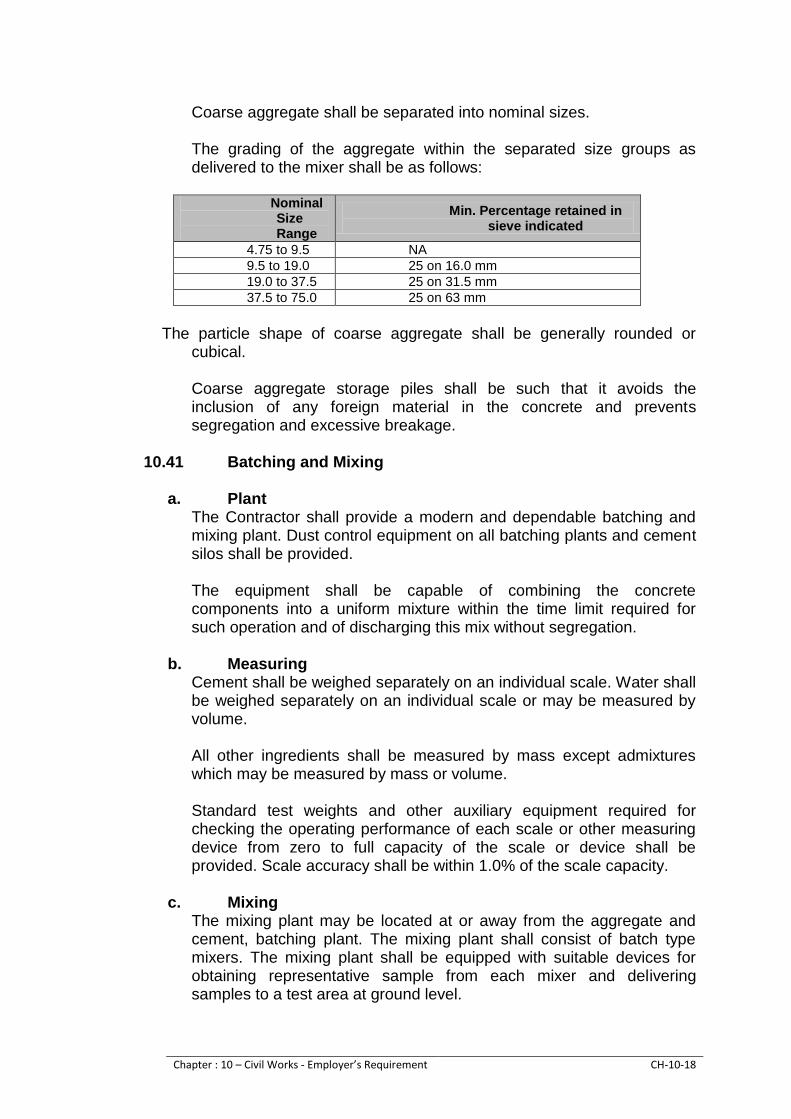
Chapter : 10 – Civil Works - Employer’s Requirement CH-10-18
Coarse aggregate shall be separated into nominal sizes. The grading of the aggregate within the separated size groups as
delivered to the mixer shall be as follows:
Nominal Size Range
Min. Percentage retained in sieve indicated
4.75 to 9.5 NA
9.5 to 19.0 25 on 16.0 mm
19.0 to 37.5 25 on 31.5 mm
37.5 to 75.0 25 on 63 mm
The particle shape of coarse aggregate shall be generally rounded or
cubical. Coarse aggregate storage piles shall be such that it avoids the
inclusion of any foreign material in the concrete and prevents segregation and excessive breakage.
10.41 Batching and Mixing a. Plant
The Contractor shall provide a modern and dependable batching and mixing plant. Dust control equipment on all batching plants and cement silos shall be provided.
The equipment shall be capable of combining the concrete
components into a uniform mixture within the time limit required for such operation and of discharging this mix without segregation.
b. Measuring
Cement shall be weighed separately on an individual scale. Water shall be weighed separately on an individual scale or may be measured by volume.
All other ingredients shall be measured by mass except admixtures
which may be measured by mass or volume. Standard test weights and other auxiliary equipment required for
checking the operating performance of each scale or other measuring device from zero to full capacity of the scale or device shall be provided. Scale accuracy shall be within 1.0% of the scale capacity.
c. Mixing
The mixing plant may be located at or away from the aggregate and cement, batching plant. The mixing plant shall consist of batch type mixers. The mixing plant shall be equipped with suitable devices for obtaining representative sample from each mixer and delivering samples to a test area at ground level.

Chapter : 10 – Civil Works - Employer’s Requirement CH-10-19
The mixing plant shall include a device for counting and automatically recording the number of batches mixed.
The batching and mixing plant shall have arrangements for reading
wastage of any material or concrete that is improperly batched, mixed or held in the mixers too long.
d. Testing and inspection facilities
Facilities shall be provided by the Contractor at the Contractor’s batching plant and mixing plant for concrete control testing. The facilities shall include a plant inspector’s enclosure with desk and platforms for obtaining handling and testing samples of aggregates and plastic concrete.
e. Conveying The method of transporting concrete from the batching plant to the
position of placing shall be such that segregation does not occur. f. Placing
No concrete shall be placed in any location until all transport and placing arrangements, formwork, installation of reinforcement and embedded parts and preparation of surfaces against which the concrete is to be placed have been prepared and checked in accordance with the Contractors control procedures.
Surfaces upon which concrete is to be placed shall be free from
standing water mud debris, oil and loose or unsound fragments. Concrete shall be worked readily into the corners and angles of the
forms and around all reinforcement and embedded items without permitting the component concrete materials to segregate.
The Contractor shall provide equipment adequate for handling and
placing concrete containing the maximum aggregate size and low slump concrete mixes.
Concrete shall be deposited, in all cases, as nearly as practicable,
directly in its final position and shall not be caused to flow such that the lateral movement will permit or cause segregation of the coarse aggregate, mortar, or water from the concrete mix.
Once placement of concrete has commenced in a location, placement
shall not be interrupted by diverting the placing equipment to other locations.
All concrete that can be properly placed within specification
requirements for slump and temperature, and can be properly consolidated without re-tempering, shall be classified as being placed within the time limit.
g. Concreting during Hot Weather

Chapter : 10 – Civil Works - Employer’s Requirement CH-10-20
During the placing of concrete during hot weather the Contractor shall comply with the recommendations contained in the Manual of Concrete Practice Part 2 1989, “Hot Weather Concreting – American Concrete institute 3058 77”
h. Joint Spacing The joint spacing including construction, control and contraction joints
shall be as shown on the Drawings or as otherwise consented by the Employer.
i. Lift in Concrete
The maximum permissible depth of concrete placed in one lift or course shall be as shown on the Drawings for each structure or as otherwise consented by the Employer.
j. Consolidation of Concrete Concrete shall be compacted with the aid of mechanical vibrating
equipment and may be supplemented by hand spading, tamping and rodding as required and consented to by the Employer. Consolidation of concrete shall be by electric or pneumatic drive immersion type vibrators or form or surface vibrators of sufficient power and capacity to consolidate the concrete effectively and quickly.
The duration of vibration shall be limited to that necessary to produce
satisfactory consolidation without causing objectionable segregation. k. Placing concrete in Conduit
Concrete in the conduit shall be placed by pumping or other non-pneumatic methods. If pumped, the end of the discharge line shall be kept well buried in the concrete during placing to assure complete filling, after the concrete has been built up to the crown. Special care shall be taken to force concrete into all irregularities and to completely fill the corners.
10.42 Construction Joint Treatment
Construction joint shall be clean and wet when covered with fresh
concrete. Construction joint shall be prepared by cleaning with high pressure water blasting. The operation shall be continued until all loose or defective concrete and all surface skim of mortar, laitance, coatings, stains, debris, and other foreign materials are removed.
10.43 Water Stops
Water stops shall be installed as per BS8007 where required and in
joints as shown on the Contractor’s Drawings. All Water Stops shall be installed so as to form a continuous watertight
diaphragm in each joint. Adequate arrangement shall be made to support and completely protect the water stops during the progress of the work. Water Stops punctured or otherwise damaged shall be replaced or repaired.

Chapter : 10 – Civil Works - Employer’s Requirement CH-10-21
Particular care shall be taken to ensure that concrete in the vicinity of
water stops is adequately compacted whilst avoiding damage to the Water stop.
10.44 Forms Forms shall be used wherever necessary, to confine the concrete and
shape it to the required lines. Forms shall have sufficient strength to withstand the pressure resulting from placement and vibration of the concrete and shall be maintained rigidly in correct position. Forms shall be sufficiently tight to prevent loss of mortar from the concrete.
Forms for exposed surfaces or water passages shall be constructed so as to produce a uniform and consistent texture and pattern on the face of the concrete. The forms shall have Formica cladding.
The forms shall be constructed so that the structure components will be true to line and grade. The forms shall be checked before concreting to produce structures within specified tolerances. Tolerances shall be indicated, in the Contractors Drawings.
At the time concrete is placed in the forms, the surfaces of the forms
shall be free from encrustation of mortar, grout, or other foreign materials that would contaminate the concrete or interfere with the finish of formed surfaces.
Before concrete is placed the surfaces of the forms shall be oiled with a
commercial form oil that will effectively prevent sticking and will not stain the concrete surfaces
Forms shall be removed carefully, so as to prevent damage to the
concrete.
10.45 Curing and Protection All concrete shall be moist cured for a period of not less than 14
consecutive days by an approved method or combination of methods applicable to local conditions. All equipment needed for adequate curing and protection of the concrete shall be available and ready to install before actual concrete placing of each placement begins.
The Contractor shall protect all concrete against damage until final
acceptance.
10.46 Finishes and Finishing The class of finish shall be to suit the Contractors Design and shall be
indicated on the Contractors Drawings.
Chapter : 10 – Civil Works - Employer’s Requirement CH-10-22
Class F1: General for unexposed surfaces such as those against which backfill or further concrete will be placed. The surface shall be free from void and honeycombed areas.
Class F2: For surfaces permanently exposed to view but where the
highest standard of finish is not required. Finish is intended to be left as struck. Minor blemishes and discoloration will be permitted.
Class F3: Formwork shall be lined with Formica or a material that produces a smooth finish of uniform texture and appearance. The lining material shall leave no stain on the concrete and shall be so joined and fixed to its backing that it imparts no blemishes.
Class U1: The concrete surface shall be uniformly leveled and
screeded to produce a plain even uniform surface to the profile shown on the, Construction Drawings. No further work shall be carried out to the surface unless it is used as the first stage.
Class U2: Floated Finish After the concrete has hardened sufficiently the Class U1 surface shall be floated by hand or machine sufficiently only to produce a uniform free from screed marks.
Class U3: Trowelled Finish. When the moisture films have disappeared
and the concrete has hardened sufficiently to prevent laitance from being worked to the surface, the Class U3 surface shall be steel trowelled under firm pressure to produce a dense, smooth, uniform surface free from trowel marks.
Class U4: Brushed Finish. The surface shall be treated as U2 and then
lightly brushed with a stiff brush to produce a textured finish.
10.47 Steel Reinforcement a. General
All steel reinforcement including rods, wire fabric, and anchor bars shall be detailed, furnished cut bent and placed as shown on the Drawings. All reinforcement shall be free from loose flaky rust and scale, and from oil, grease, mud, mortar, or other coatings which might destroy or reduce its bond with concrete or grout.
b. Cutting and Bending
Steel reinforcement may be mill or field bent. All bending shall be in accordance with standard approved practice and shall be performed by approved mechanical methods. Heating of reinforcement for bending will not be permitted. Bars with kinks or bends not shown on the Drawings shall not be used.
c. Type
Steel reinforcement shall conform to the standards defined in the Contractors Design and consented by the Employer. As a minimum the reinforcing steel shall comply with the requirements of ASTM A615M, Grade 300 or 420. However, reinforcing steel for earthquake resisting frames shall comply with the requirements of ASTM A706M. The use of

Chapter : 10 – Civil Works - Employer’s Requirement CH-10-23
locally available reinforcing steel meeting the requirements of this section is acceptable. Each delivery of reinforcement delivered to site shall be individually identifiable by suitable tags and accompanied with the associated test certificates confirming the test results.
d. Splicing
All splices in reinforcement shall be as shown on the Drawings. Adjacent sheet of mesh reinforcement shall be spliced by lapping as shown on the Contractor’s Drawings.
e. Supports
All reinforcements shall be secured in place by use of approved metal or concrete supports, or ties. Such supports shall be of sufficient strength and of sufficient number to maintain the reinforcement in place throughout the concreting operation. The supports shall be used in such a manner that they will not be exposed or contribute, in any way, to the discoloration or deterioration of the concrete.
f. Quality Control
The Contractor shall control the quality of his work. To this end the Contractor shall submit his quality control and quality assurance procedures to the Employer for consent.
10.48 Fill
Scope
This section covers all work for the construction of fills including backfill
behind structures and protective layers. Selection of fill material for the Permanent works shall be as required
by the Contractors Design. Fill shall be placed in positions as shown on the contractor's drawings.
Drawings The Contractor Design shall specify the classification and type of
compaction to be employed. Compaction of fill
Wherever a density requirement of a soil or gravel layer is specified in
terms of a percentage density the Contractor shall be at liberty to employ any type of compaction equipment the he may choose in order to achieve such density over the full specified depth of the layer, provided that the equipment employed is adequate and suitable for the purpose and is in no way detrimental to any part of the Works and the successive layers bind together all to form an integral mass.
The dimensions of fills shall be in accordance with the type of cross
section details shown on the Contractor's Drawings.

Chapter : 10 – Civil Works - Employer’s Requirement CH-10-24
The thickness of individual layers shall depend on the type of material used and the maximum size of the particles in such material.
Where the material can generally be broken down to a maximum size
of 200 mm, the layer thickness shall not exceed 250 mm after compaction except in the case of cohesion less sands where layer thicknesses of up to 400 mm may be employed.
In the case of material that cannot be reduced to a maximum size of
200 mm or less after removal of the oversize material, thicker layers shall be constructed but the thickness of the loose layer shall not be more than is necessary to ensure that the maximum particle size is generally not more than the completed layer thickness.
Fill shall be placed in successive horizontal layers parallel to the final fill surface, and the construction of tapered layer shall be restricted to the bottom layers of fill where it may be unavoidable due to cross fall or tapering out of fills.
Rock material containing rock particles greater than 200 mm in size
shall not be used at a depth of less than 150 mm below the top of fill level unless consented by the Employer.
Finishing of Slopes Fill slopes shall be finished to neat lines with all lose rocks and
uncompacted material removed. The degree of finish required shall depended on the nature of the material used for the fill slopes but-it shall be as smooth as is consistent with the material involved and good workmanship.
Protection of Fills All permanent drains shall be constructed as soon as possible plus
sufficient additional temporary drains as may be necessary to protect the fill, and they shall be maintained in good working order. Ruts and potholes developing in the fill after completion shall be repaired, and damaged sections of the fill shall be reshaped and re-compacted.
All fill slopes shall be maintained by the Contractor until acceptance of
the fill. All erosion and floor damage to slope shall be promptly repaired.
10.49 Architectural Finishing General
This Clause covers the architectural finishing and works required under the Contract.
The Contractor shall develop a schedule of finishes and associated
specifications for the Employer consent. Types of Finishes and fittings shall be shown on the Contractor’s Drawings and shall be consistent with the agreed schedule.

Chapter : 10 – Civil Works - Employer’s Requirement CH-10-25
The Contractor shall submit, to the Employer for his consent, specimens of materials for colour and finish for the items requiring the Employer Consent, at least 28 days prior to the date he wishes to place order.
All building construction and finishing work shall be performed by
experienced skilled labour. Finishing Works shall not commence until the area concerned is arid,
such adjacent areas which may affect the finishing work have been weatherproofed, and the concrete or other materials have dried out sufficiently.
Permanent openings shall be finished neatly and the Contractor shall
furnish and cut as required such special shapes of materials as are required for neat finishing at edges. Where required in suspended ceilings access openings neatly finished at edges shall be formed by the Contractor and fitted into the openings in such a manner as to blend with the ceilings.
Where walls, floors or ceiling are to receive a plastered, tiled or painted
finish, the Contractor shall prepare for consent of Employer, trial panels, approximately one meter square, be erected in the locations where the particular types of finish are required. The trial panels will be required to demonstrate the final appearance of the finish which may be required at a particular location.
The Contractor shall provide and maintain adequate protection from
damaging of the finishing throughout the Contractor period. Concrete Work
Reinforced or plain Cement Concrete. Concrete in structures and chambers etc. shall be in all circumstances
fair faced finish and in no case repair shall be allowed. Any fins shall be removed and finished smooth with a rich cement slurry.
Edges where exposed shall be chamfered to a size of 1-1/2” x 1-1/2”
Block Work Block work shall confirm BS 6073 Part 1. Type B with average
compressive strength not less than 7.0 N/mm2. Block shall be solid, hollow or cellular, beded and jointed in mortar
average 10 mm thick. Cellular blocks shall be laid with cavity downwards.
Internal faced work for painted finish shall have flush jointing as BS
5628, and be left fair clean face ready decoration. Internal wall shall be solid block 150 mm thick.

Chapter : 10 – Civil Works - Employer’s Requirement CH-10-26
External walls shall be 600 mm thick in cavity design. Where block work is to be rendered or plastered joints shall be raked
out to a depth of 12 mm. Metal anchors for fixing block work to concrete shall be stainless steel
conforming to BS 1449, min: tensile strength of 400 N/mm2, 4.5 mm thick x 35 mm min: width length to such cavity.
Stainless steel butterfly wall ties shall be built into cavity.
Plastering Internal plastering shall be 12.5 mm thick carried out in accordance
with BS 5492 using cement mortar in the ratio of 1:4. External rendering shall conform to BS 5262 and the surfaces shall
have 18.75 mm thick cement plaster with mechanical spray plaster finish in white cement with colour pigment and white marble chips of zero “0” No. in the ratio 1:2. Panels 900x900 with engraved separation joints (visual) shall be made.
Stainless steel angle bead conforming to BS shall be fixed at all
external angles. Floor Finishes
The floor finish shall be over the base course in case of ground floor or
directly on reinforced concrete slab. The floor finishes shall be either cement concrete, Mosaic, Marble or Ceramic tiles, to suit the requirements of the location and as approved by the Employer. The Contractor shall be responsible for ensuring that the background or sub base to which the specified finish is to be applied, has properly cured and is properly finished and is completely adequate to receive the specified finish.
All materials likely to reduce adhesion of the finish shall be removed
prior to the application of the specified finish and the surface left dust free and clean and protected from contamination until time of laying finish.
Surfaces to receive adhesives and fixatives shall be thoroughly dry. Surfaces that are to receive cement mortars shall be roughened and
dampened prior to the application of the mortar; All traffic and loads shall be kept off completed work at least until
bonding has set. If possible, areas shall be locked up on completion of finishing work.
Plain Cement Concrete Floor

Chapter : 10 – Civil Works - Employer’s Requirement CH-10-27
Plain cement concrete floor shall be laid in the ratio of 1:2:4 of minimum thickness 75 mm over the base concrete. Floor of the Transformer Room shall be in cement concrete.
Terrazzo Floor Terrazzo floor shall be laid in the Motor Hall and Store Room in grey
cement. Marble chips shall be No. 1 to 4 of approved colour having an abrasive hardness of min: 16 as determined by National Bureau of Standard Report BMS 98. The flooring shall be laid in panels using 25 mm thick plate glass strips for separation.
Butecena Marble Tiles
Butacena Marble floor Tiles of approved colour shall be laid in office,
control rooms and SCADA room. The size of the tiles shall be 450 x 450 mm laid over min: 37.5 mm thick CC 1:2:4 base.
Acid Resistance Tiles Acid Resistance Tiles flooring shall be laid in Battery room.
Non-Skid Ceramic Tile
Non-skid Ceramic Tile flooring shall be provided to Bath rooms. The tiles shall conform to BS 1281 and of colour and size 300 mm x 200 mm as approved by the Employer.
Wall Finishes The Contractor shall ensure that the background or sub base to which
the specified finish is to be applied has properly cured and is properly finished and is completely adequate to receive the specified finish.
Surfaces which are to receive finishes shall be cleaned free from loose
materials fines, encrustations, oil, paint, dirt and any other material that might percent satisfactory bond.
Surfaces to receive adhesives or fixatives shall be thoroughly stained with Masking tape where necessary to prevent staining of adjoining work such as windows and door frames.
a. Tiling / Dado / Skirting
In general it shall conform to BS 5385 The Contractor shall submit to the Employer for his consent, loose
samples of each type of tile or other unit finish required. Samples shall be sufficient in number to illustrate the extremes and average of the ranges of colour, size and texture.
Only whole tiles are to be used, where practicable equal margins of
cut tiles larger than half a tile. Joints in all tiled panels shall be set out to the manufacturer’s
recommendations.

Chapter : 10 – Civil Works - Employer’s Requirement CH-10-28
Tiles shall be kept free of traffic for a minimum period of 72 hours after
laying. Protection following laying shall be adequate to withstand all damage. The Contractor shall furnish additional spare materials of the same
type, quality and colour equal to 1 per cent of quantity of each type laid. These tiles and skirting’s shall be packed and labeled suitable for storage.
Tiling shall be glazed ceramic wall tiles conforming to BD 1281 and will
be provided in Bathroom’s upto 2100 mm height. Skirting shall be in Butacena brown marble tiles and provided to office
room upto 150 mm height. Dado in glazed ceramic brown marble tiles 400 x 400 smoke colour
shall be provided in Motor Hall, SCADA room and control room upto 2100 mm height. The tiles in addition to normal procedure for fixing with chemical bond shall be fixed with galvanized iron screws and surface finished smooth to match.
b. Stairs
Stairs to basement (motor hall) from ground floor shall be RCC and
have chequered surface finish. Stair treads and risers to Motor Hall from finished ground shall be 1875
mm thick marble tiles laid over 37.5 mm thick CC 1:2:4 bases. c. Doors
Frames for the doors shall be of steel conforming to BS 1245 and BS
4737 Part 1 and galvanized in accordance with BS 729. Frames shall be built in as work proceeds with the fixing camps securely bedded into the clock work courses without disturbing any damps proof course. Frames shall be painted externally with on approved gun applied butye or poly sulpine non-setting mastic and finish to match with the finish of the doors.
Doors shall by double or single leaf panel doors made from 1st quality.
Deodar wood and timber coating finish, or enamel paint finish as approved by the Employer.
Steel door where required shall be of an approved type. These shall be manufactured from steel sheet conforming to BS 1449, part 1 and of all welded construction with internal angle reinforcing grid. Facing sheets shall be minimum 1.6 mm thickness cold rolled leveled sheets. External doors shall be 44 mm thickness and internal doors 35 mm thick with all necessary reinforcement for hangers, locks and other furniture.

Chapter : 10 – Civil Works - Employer’s Requirement CH-10-29
d. Roller Shutter Doors Roller shutters shall be sliding type installed in accordance with the
manufacturer’s requirements and from minimum 18 gauge steel employing convex type lath.
Unless otherwise shown in the Contractors Drawings and consented to
by the Employer, roller shutter shall be manually operated on the inside of the building. The mechanism shall be lockable.
Not less than 28 days before proceeding with fabrication the Contractor
shall submit shop drawings of the roller shutter to the Employer showing sections, dimensions, fixings and other information as may be required by the Employer for his consent.
e. Door Furniture
All hardware shall be manufactured to a strong, durable and secure
pattern. The Contractor shall submit to the Employer for consent samples of door furniture to be used in the works.
Unless otherwise shown in the Contractors Design, iron or steel for
building into brick, stone or concrete masonry shall be hot dip galvanized or coated with 2 coats of aluminum paint. All other iron and steelwork shall be given two coats of rust inhibiting paint before fixing.
f. Windows and Ventilators
Minimum 20% area of the wall surface exposed to the outer
atmosphere shall be provided with fully double glazed aluminum windows and ventilators. The windows and ventilators will be of aluminum. The Contractor shall submit to the Employer for consent samples of windows to be used in the works.
Prior to installation, all items of windows and ventilators shall be
protected from the weather, stored level on the ground and stacked in the way that allows free air circulation around the items. Installed windows and ventilators shall be protected from mechanical damage as required.
The frames shall be accurately set out and assembled square arid true.
All necessary accessories and fixings for the proper completion of the Works shall be provided.
Window and ventilators shall be plumb, Square and level and firmly
fixed by approved devices. The frames shall be from an approved manufacturer and fabricated
from H9 aluminum alloy in accordance with BS 4873. They shall be of the type and to the dimensions shown on the Drawings, fully weather stripped. Surface finish shall be anodizing to BS 3987 to provide an

Chapter : 10 – Civil Works - Employer’s Requirement CH-10-30
anodic coating of 25 micron average thickness over mechanical stain finish.
Fittings shall be manufacturers standard type. All windows and
ventilators should be provided with 20 mm square galvanized steel wire mesh.
Pre-finished surfaces shall not be allowed to rub or slide against each
other and shall be well protected during transportation and storage. Glazing shall comply generally with BS 6262. Glass shall unless
otherwise shown be 5 mm thick clear ordinary glazing quality complying with BS 952 except where required to be thicker minimum 12 mm in accordance with BS 6262.
Reinforced glass shall be 12 mm 6 mm thick with straight wires both
ways to form 13 mm squares in accordance with BS 952. Glass panels for offices and Panel room shall be reinforced glass min
12.0 mm thick with aluminum framework as approved by the Employer. Putty shall be approved metal casement type of approved colour for
metal and hardwood frames and linseed oil type complying with BS 544 for softwood frames. Rebates shall be sealed before glazing with primer for softwood frames and the finish varnish for hardwood frames.
All glass shall be left clean inside and out free from all scratches or
other blemishes on completion. g. Plumbing Fittings & Fixtures
HDPE - 100 pipe and fittings shall be used in all plumbing works. The pipes in the wall shall be encased or ducted and in the floor in
covered ducts only. Fixtures shall be of Master or equivalent make and as approved by the Employer.
The whole of the plumbing fittings, fixtures and their installation
complete shall be in accordance with all relevant regulations of the appropriate local Authority or Government Authority.
Generally all pipework shall be embedded in walls, placed in wall
chases to be provided and tiled in or taken up in ducts and concealed from view.
Surface mouthed pipework shall be adequately and suitably fixed in position in accordance with the best practice and in accordance with the applicable specifications.
The Contractor shall furnish and install the fittings and features in the locations as shown on Contractor’s Drawings.
Wash basins and toilet pans shall be defined in the Contractor
Drawings.

Chapter : 10 – Civil Works - Employer’s Requirement CH-10-31
Wash Basins toilet pans shall be white vitreous china of the best quality
made in Pakistan. Bath for the office shall be provided with one European type pan toilet
pan and one wash basin mirror and rack. Bath for the staff shall be provided with one Asian type toilet pan and
one European type. The two pans shall be further provided with partitions and separate doors. Wash basin shall be common.
Contractor’s Facilities Contractor’s Site office
The Contractor shall provide the Site office and other facilities for its
own use at a place approved by the Employer. Contractors Laboratory Facilities
The Contractor shall, for the duration of Contract, supply, maintain and operate a materials testing laboratory at site necessary for sampling preparing and testing materials as specified. The Contractor may also use an off-site testing laboratory to perform certain of the specified tests Both the laboratory and the test shall be to the approval of the Employer such approval shall not be given if significant delays in obtaining results are likely, or if the results may be unreliable. The Contractor shall make all the necessary arrangements and provide all transport and labor for conveying the samples to the Employer promptly. The Employer approval will be withdrawn if the service proves in any way unsatisfactory.
The Contractor shall provide trained and experienced Material
Engineer technician and skilled labor to carryout specified tests to the satisfaction of the Employer. The Material Engineer and technicians shall be approved by the Employer. In case of unsatisfactory performance such approval will be withdrawn and the Contractor shall arrange for suitable replacement for approval by the Employer.
The Employer and his supervisory staff shall have access to the
laboratory to supervise testing and to witness verification tests ordered by the Employer or his staff.
The Contractor shall keep record of all tests he conducts in connection
with compliance with, and as, required by the Specifications, and shall supply copies of the results of such tests to the Employer as soon as practicable after each test is made.
Notwithstanding the above the Contractor shall supply, maintain and
operate all the necessary apparatus for certain tests which shall be carried out within the Permanent Works or elsewhere on the Site as directed by the Employer. The Contractor shall locate the laboratory at location approved by the Employer.

Chapter : 10 – Civil Works - Employer’s Requirement CH-10-32
The Employer Site Laboratory shall be provided with testing equipment
with consumables for following tests and maintained for the duration of the Contract.
10.50 Security, health and safety
The Contractor will provide the Employer with a security, safety and health manual within one month of Notice to Proceed, covering all aspects mentioned in sub-clauses and other relevant clause of the EPC Contract, Laws and Regulations of Government of Pakistan and Government of Sindh relevant international standards, tradition & customs of Sindh and in accordance with relevant section of this Volume.
10.51 Furniture and equipment for the office in the Pump House
The Contractor shall supply the furniture, fittings and equipment listed below and installs them in the Employer offices within the pump house. They shall be for the sole use of the Employer and his staff and employees of the Employer. All furniture, fixtures and equipment shall be supplied new, and manufacturer’s description or sample shall have been approved by the Employer before any item is ordered. The Contractor shall keep insured all furniture, fitting and equipment supplied to the Employer to their full local value (including duty) until the end of the Defects Liability Period when the same will be handed over to the Employer in satisfactorily working condition and shall remain Employer’s property.
Concrete cube crushing strength testing machine & 3 sets of cube moulds
01 No
Speedy moisture tester (20 gms) complete test
02 Sets
Determination of dry density/moisture content, relationship of soil
01 Set
Aggregate moisture test for determination of water cement ratio (200 mm dia complete test)
02 Sets
Slump cone with base plate
03 Nos
Cement briquette moulds
02 Sets
Flakiness index test equipment for aggregate
02 Nos
Field density measuring equipment (sand cone)
03 Sets

Chapter : 10 – Civil Works - Employer’s Requirement CH-10-33
The offices shall be adequately furnished equipped and maintained for proper use and functioning, all to the satisfaction of the Employer. The furniture and equipment listed herein is the minimum and may be varied or substituted by the Employer with other or additional items to meet his requirements.
a) Furniture:
All furniture will be made from best quality Oak wood, stainless steel metal work, best quality lock, and polish on the wood work of high quality, all as approved by the Employer.
1
Officers table 5½’x 3’ with 4 drawers and glass top
along with attached side rake 3’x½’ also glass top
4 Nos
2
Table 5’x3’ with 3 drawers on each side
4 Nos
3
Conference Table 21’x5’
1 No
4
Central Table 3½’X3½’ with glass top
4 Nos
5
Officers chair revolving with arms and upholstered
4 Nos
6
Upholstered chair with arms.
4 Nos
7
Upholstered chair with arms for conference room
25 Nos
8
Reclining easy chairs
2 Nos
9
Steel filing cabinets with locks & suspended filing
system
4 Nos
10
Steel racks for tools with lockable drawers -6’x4’x1.5’
4 Nos
11
Plane chest 5’X3’ deep X 4’ high
4 Nos
12
Waste paper baskets
10 Nos

Chapter : 10 – Civil Works - Employer’s Requirement CH-10-34
13
Glass Ash trays
10 Nos
14
Sundry office items like letter tray, punch, paper,
stapler, pencil holder, pencils, sharpeners and erasers
10 sets
b) Kitchen items
1 No frost frigidere -8 cft
1 No
2 Tea cattle stainless steel – 1 Litre
2 Nos
3 Electric cattle -1 litre
1 No
4 Tea mugs china ware
12 Nos
5 Tea cups with saucers china ware
24 Nos
6 Half plates china ware
24 Nos
7 Quarter plates china ware
24 Nos
8 Sugar pot china ware
6 Nos
9 Milk pot china ware
6 Nos
10 Table spoon stainless steel
24 Nos
11 Tea spoon stainless steel
24 Nos
12 Sauce pan stainless steel
2 Nos
13 Cess-rolls stainless steel
2 Nos
14 Spoons for item 12 & 13
4 Nos
15 Cooking range with 4-burners with gas cylinder
1 No
16 Service cabinet 6’x2½’x3’
2 Nos
17 Medium size serving dishes
6 Nos
18 Medium size service bowl
6 Nos
19 Forks stainless steel 12 Nos
20 Service trays 4 Nos

Chapter : 10 – Civil Works - Employer’s Requirement CH-10-35
21 Water glasses 12 Nos
22 Water jugs 4 Nos
The Kitchen to be provided with suitable fittings and fixtures.
c) Wash rooms & Toilets
Wash rooms/toilets to be provided with best quality fittings and fixtures of local origin but with prior approval of the Employer. English w/c and Asian w/c both are to be provided, with telephone showers. Wash basin and Mirror to be provided in the Bath rooms.
10.52 Surveying Instruments and Surveyors
The Contractor shall provide and maintain the following survey equipment on site for the sole use of the Employer and his staff for the duration of the Contract.
a. Total Station (One second Accuracy) b. Automatic Level c. Level Staff d. Ranging Rods e. Tripod Stan f. Prism g. Prism Holder h. Measuring Steel Tape 100 meter
The contractor shall provide a competent and experienced surveyor with two assistants and necessary labour along with transport for the survey work. The survey staff and transport for surveyors shall be maintained with driver consumables, POL, spares and insurance and shall be solely at the disposal of the Employer and his staff. On completion of the work, the survey instruments and the transport will be returned to the contractor.
10.53 Transport for the Employer
The Contractor shall provide new approved vehicles as listed in the Schedule of Prices, for the use of the Employers and his staff and Employer. Vehicles shall be equipped with spare water and fuel containers, roof rack and be suitable for tropical use. Kerb weight and tyre pressures shall be stated on each vehicle and the vehicles shall conform in all respects to the regulations of the appropriator registration authority.
The Contractor shall provide competent drivers to the approval of the Employer for the vehicles used on site. The Contractor shall provide all

Chapter : 10 – Civil Works - Employer’s Requirement CH-10-36
fuel, lubricants, etc and shall license, insure (as detailed below), servicer and maintain the vehicles in a roadworthy state. The Contractor shall be obliged to have ready access to spare parts appropriate to the number, type and duty of the vehicles supplied. If in the opinion of the Employer the Contractor should default in this respect and deprive the Employer of use of vehicle(s) made unserviceable by normal use in the conditions and demands of the Site, the Contractor shall provide suitable alternative transport to the approval of the Employer. If the Contractor fails to provide this service the Employer shall be entitled to withhold the issue of a Payment Certificate until the service is resumed. Insurance for vehicles must be comprehensive and include: Cover for the Employer and his staff driving the vehicle;
Liability to third parties (including passengers whether the Employer his staff or others) for an unlimited indemnity in respect of death or personal injury and for the maximum indemnity reasonable obtainable in respect of loss, destruction or damage to property. The vehicles shall be handed over to the Employer at the end of the Defects Liability Period or earlier if order by the Employer and transferred in the name of the Employer. For a site movement of Employer Supervision staff for inspection of Contractor’s works or in connection with the works, the Contractor shall make available suitable transport as required. No direct payment shall be made for this and the cost thereof is deemed to be included in the contract price.
10.54 Telephones
The Contractor shall provide following communication facilities for the sole use of the Employer and his staff. The Mobile telephone (3 nos.) shall be portable hand held cellular type as Motorola Model Vader, manufactured by Motorola Inc. or similar approved by the Employer, with all charges to be paid by the Contractor to keep the phones working throughout the Contract period. One landline telephone shall be provided in the site office of Employer and on Fax machine of approved make. The Contractor shall bear the cost of installation, instruments and payment of telephone bills regularly to keep telephone in service continuously until the end of Defects Liability Period. The Contractor shall maintain the Fax machine with provision of all consumables until the end of Defects Liability Period.

Chapter : 10 – Civil Works - Employer’s Requirement CH-10-37
One completion of work, the telephone (other than mobile phone) and Fax machine will be the property of the Employer and will be handed over to him.
10.55 Health and Safety
The Contractor shall provide for the health and safety of its employers, any employees of Employer and any other persons who are at any time directly or indirectly effected by the performance of the Work by an application of a suitable or acceptable health and safety policy that ensures attention to the safety of work sites, to safe methods of working, to the suitability of personnel by training or placement and by adequate supervision. The Contractor shall be under an obligation to take all reasonable safety measures in relation to the type of services undertaken and shall conduct itself and all personnel assigned to the Work and perform the Work in such a way as to comply at all times with its obligation and duties under laws, regulation, rules, order and other enactments in force from time to time relating to health and safety matters, including the Employer’s safety requirements. The Contractor shall in addition observe and follow all guides, codes and recommendations issued or made by the government, professional or trade organization or other official or responsible organization relating to health and safety at work as applicable to the project. At every site where the work is being performed under this Contract the Contractor will appoint a safety who will be responsible for all personnel engaged in the performance of the work under this contract including those of the Contractor’s sub-contractor. The contractor will draw up and ensure compliance with safety regulations commensurate with the hazardous nature of work.
10.56 Quality assurance / quality control The Contractor will instigate a QA/QC programmed in accordance with the relevant Clause of the EPC Contract.
10.57 General a. Description
The Contractor shall be completely responsible for implementing a Quality Assurance Plan covering all the Works contained in the Contract including the design. The Quality Assurance Plan will be prepared by the Contractor and reviewed and authorized by the Employer and will be implemented by the Contractor. It will be especially managed by the Contractor’s Resident Quality Assurance Manager. The contractor’s Quality Assurance Plan means by which the Contractor ensures the control and quality of all design function, all fabrication by his vendors and sub-contractors and all construction activities carried out by his sub-contractors.

Chapter : 10 – Civil Works - Employer’s Requirement CH-10-38
10.58 The Contractor’s Quality Assurance Plan The Contractor’s Quality Assurance Plan shall meet all the
requirements of the International Standards Organizations known as ISO 9001. As appropriate the Contractor will impose on his designers, Vendors, fabricators and sub-contractors the requirements of ISO 9002, ISO 9003 and ISO 9004.
The Quality Assurance Plan will be prepared and presented in three different volumes namely:
Volume 1 Quality Plan Volume 2 Quality Assurance Procedures Volume 3 Quality Control Procedures
Collectively the three Volumes will comprise of the Contractor’s Quality
Assurance Clan. Each volume will address the issues enumerated in the following Articles of this Section.
The Quality Assurance Plan shall recognize the necessity for revision
during the project at which time reauthorization shall be sought from the Employer.
Within twenty-one (21) days of the date of the Notice to Proceed the
Contractor shall produce and submit to the Employer an outline of the QA Plan. Within a further 28 days of the above submittal date the Contractor will submit the detailed QA Plan incorporating the comments made by the Employer. The authorized detailed QA Plan will be supplemented by comprehensive details for specific work activities at least 28 days prior to their commencement.
The Contractor’s Quality Assurance Plan will be managed and directed
by a dedicated Resident Quality Assurance Manager who will be physically on the project Site throughout the implementation and will report directly to both the Contractor’s Site Project Manager and independently and directly to the Contractor’s Home Office Senior Management.
10.59 Requirements of the Contractor’s Quality Assurance Plan
Volume 1 : Quality Plan This section of the Contractors Quality Assurance Plan will address the
following topics:
(1) Purpose and Scope Policy (2) Organization and Responsibilities (3) Project Manager Review (4) Applicable Standards (5) Definitions

Chapter : 10 – Civil Works - Employer’s Requirement CH-10-39
The purpose scope and policy chapters will establish the general philosophy and parameters that the Contractors Senior Management require for the Quality Assurance Plan.
Organization and responsibilities will clearly present the detailed
Contractor’s Organization as it pertains to Quality Assurance and Quality Control activities. A description of assigned responsibilities is required.
Project Management Review will address the Contractors procedures for addressing quality issues raised by the Resident Quality Assurance Manager to the Site Project Manager and Head Offices Senior Management.
The standards that will be used to support the Contractors Quality
Assurance Plan are required to be listed. This will include all applicable industry codes, standards and practices and specifically those referenced in the contract Document and Employer’s Requirements.
For clarity in the use of the Contractor’s Quality Assurance Plan
document by Contractor’s personnel it is required that a glossary of specific terms used in the documents be itemized (Definitions).
Volume 2 : Quality Assurance Procedures
This Volume will present clearly the procedures developed by the
Contractor to provide a planned and disciplined approach for the achievement of project quality objectives. The procedures, in general require the prompt detection and correction of deviations, which are or may be detrimental to quality and generate documentation necessary to provide objective evidence of achievement of quality objectives during design, fabrication, construction and commissioning phases of the project.
As a minimum the QA procedures will include but not limited to: (1) Contractors procedures addressing the requirements of ISO standards. (2) Plant Management Procedures. (3) Construction Schedule Management. (4) Progress Reporting Procedures. (5) Design Procedures. (6) Procedures for selecting and appointing sub-contractors and vendors.
(7) Procedures for obtaining, reviewing and approving sub-contractors and vendors quality procedures.
(8) Procedures for auditing sub-contractors and vendors. (9) Contractors Method Statements for all work activities. (10) Document Control Procedures. (11) Environmental Management Procedures. (12) Health and Safety Procedures. (13) Audit and Surveillance Program and Schedule by Resident QA
Manager.

Chapter : 10 – Civil Works - Employer’s Requirement CH-10-40
(14) Non-Conforming Reporting (NCR) and Deviation Report (DR) procedures.
(15) Training Procedures. (16) Interim Payment Procedures. (17) “As-Built” drawings and information procedures. (18) Operation and Maintenance Manual Procedures Change Control
of Project Quality Procedures.
Volume 3 : Quality Control Procedures This volume is dedicated solely to the procedures and systems that the
Contractor will perform to maintain an effective Quality Control (QC) program. In general the Contractor will perform sufficient checks, inspection and tests on all items of the work including:
(1) The Design Engineer (2) Vendors (3) Sub-contractors (4) Contractor’s Site Work Activities
And so ensure conformance with respect to the design, materials,
workmanship, construction, finish and functional performance. The Contractor’s QC system shall be implemented by a separate QC
organization headed by a full time QC Manager who will report to the Resident QA Manager. The QC organization will include personnel trained, specialized and qualified to inspect and test all the categories of the work. This work will include the Design Operations. Vendors and Subcontractors Consortiums operations as well as the Contractor’s own off-site and on-site operations.
The quality Control Plan shall include adequate provision for access by
the Employer to inspect any and all facilities of the project and facilities such as laboratories etc required to implement the plan.
Specifically Volume 3 will address the following items as a minimum:
(1) The QC organization. (2) The number and qualifications of personnel to be used. (3) Authority and responsibility of QC personnel. (4) Methods and procedures of QC control for all the Work including
design vendors and sub-contractors. (5) Inspection and Testing Plan. (6) Details of the site laboratory including the physical layout stalling
and proposed on-site testing equipment. (7) Details of any off-site laboratory testing. (8) Details of the physical site tests and laboratory tests proposed for
all the construction materials with emphasis on cement, concrete, soils and rock testing Frequency of Testing shall be included.
(9) Method of documenting and procedures to be followed for QC operations, inspection and testing for each section of the technical provisions. Details of proposed forms are to be included.

Chapter : 10 – Civil Works - Employer’s Requirement CH-10-41
(10) Off site testing of manufactured items and type testing. (11) Procedures that will ensure that the latest applicable Drawings,
Shop Drawings, Specifications and instructions required by the Contract Documents, as well as authorized changes, are used for fabrication, construction, and inspection and testing.
(12) Procedure for the issuance, tracking and close-out of Non-Conforming Reports (NCR’s) and Deviation Reports (DR’s). This procedure shall prioritize the NCRs and ensure the closeout of such matters in a timely manner to the satisfaction of the Employer.
10.4.1 Employer’s Quality Assurance Program It is intended that the Employer will establish his own Quality
Assurance Programme, which will be independent of the Contractor’s QA/QC programs.
The Employer’s QA program will be under the control of the Employer’s
Site Resident QA Manager who together with his staff will have the responsibility to evaluate and verify the Contractor’s QA/QC operations.
Observations, inspection, tests or approvals by the Employer’s
Resident QA Manager or any other person shall not relieve the Contractor from his obligations to perform the Work in accordance with the Contract Documents.
The Employer has the right to visual inspection of all Contractor’s
Work. If Work is to be covered, Contractor shall notify Employer’s Resident QA Manager of Work completion and Employer’s Resident QA Manager must inspect within reasonable time. If any Work is covered without such notification, it must, if requested by Employer’s Resident QA Manager, be uncovered for observation. Such uncovering shall be at Contractor’s expense unless Contractor has given Employer’s QA Manager reasonable notice of Contractor’s intention to cover such Work and Employer’s Resident QA Manager has not acted with reasonable promptness in response to such notice. “Reasonable Notice” shall never be less than 24 hours, excluding Sundays and holidays.
The Employer also has the right to carry out any physical testing of the
Contractor’s Work. Samples of Site work (e.g. concrete, soils, cement, rock, reinforcing steel etc) will be supplied by the Contractor at no charge. Furthermore, the Employer will have the right to utilize the site laboratory and staff (if necessary) to carry out verification testing, at no charge. Such verification testing by the Employer’s Resident QA Manager will be performed in an efficient and timely manner so that the Contractor’s QA/QC program is not disrupted.
The Employer will also have the right to perform any offsite testing of
materials. Samples for such testing will be supplied at no cost by the Contractor. Should any off-site testing indicate materials not meeting

Chapter : 10 – Civil Works - Employer’s Requirement CH-10-42
Contract requirements, the costs of the Employer off-site testing will be charged to the Contractor.
10.60 Environmental Compliance General
Reference is made to the environmental requirements given in:
a. The law and Regulation of Government of Pakistan arid Government of Sindh.
b. Employer’s Requirements for Environmental Protection given in this Volume.
c. Sub-Clauses 4.18 [Protection of environment], 4.22 [Security of
the Site], 4.23 [Contractors Operation at Site], 4.24 [Fossils], 6.6 [facilities for staff and Labour], 6.7 [Health and Safety], 7.3 [Inspection], 14.5 [Plant and Material Intended for the Works], 16.3 [Cessation of Work and Removal of Contractor Equipment] of General Condition of Contract and any other clause or sub-clause having any relevance to Environment.
d. Local traditions and customs of Sindh.
Miscellaneous
a. The Contractor shall within one month of receipt of Notice to Proceed, appoint an Environmental Inspector for the Works, whose broad responsibilities are to guide the construction personnel on environmental matters, to communicate and to make liaison with the Employer, Government of Sindh and local elders.
b. The Contractor shall provide Environment Management Plan of the Site as defined in this Volume.
Environmental management
a. The Contractor shall comply with all legal duties and obligations regarding the protection of the environment as laid down laws and Regulations of Governments of Pakistan and Sindh. Where there is any conflict between laws and Regulations, and clause in this specification, the more stringent requirement shall be adopted.
b. Within fourteen (14) days of the date of the letter of Acceptance the Contractor shall submit to the Employer an outline of the Contractors environmental management plan for complying with the environmental management requirements, especially as described here in this Specification. Within twenty-eight (28) days thereafter the Contractor shall submit for the Employer’s approval a detailed environmental management plan that consists of proper account of all comments made by the Employer on the outline environmental management plan. The management plan shall include, but not be limited to, the Contractors proposed arrangements for abatement and

Chapter : 10 – Civil Works - Employer’s Requirement CH-10-43
mitigation measures for environmental protection and reporting, and his organization chart showing how he delegates environmental management responsibilities on the site.
Air Quality
(i) Burning of waste will not be permitted either on or off the site.
(ii) Dust shall be kept to a minimum on the Site and at the residence area by appropriate water spray at all times.
Noise
(i) The Contractor shall take all reasonable precautions to minimize nuisance caused by noise and vibration. This may require the modification of plant where noise emissions are excessive, the construction of screens or a restriction on working hours. Where appropriate, the contractor shall provide ear protectors for staff working in the vicinity of noisy plant on site.
(ii) The Contractor will be responsible for complying to ensure the noise levels at the boundary of the project site, the worker and staff’s camp should not exceed 65 dB(A) during day time and 55 dB(A) during night times. Where the noise levels exceed those recommended, the Contractor shall propose measures that he intends to take to improve the noise levels and when approved by the Employer shall implement the proposals at no additional cost and without delay.
Waste Management
(i) The Contractor is fully responsible for the day-to-day management on waste collection and disposal. The Contractor must make arrangements for waste management for the collection and the disposal of domestic and industrial refuse, by handling, transporting or storage of schedule wastes outside the premises and its safe disposal at a location approved by the Employer.
(ii) The Contractor must ensure that all the necessary utensils such as proper storage containers or bins for refuse and kitchen wastes, special storage containers for scheduled wastes, temporary sewerage plants or toilet facilities are provided at the premises. The Contractor must also comply with the following environmental conditions throughout the construction stage:
(i) Temporary sewage treatment for toilet facilities in accordance with the specifications as prescribe by the Law and Regulation must be provided at the Contractor’s site office and worker’s camp before the commencement of any works;
(ii) Open burning of solid waste including biomass waste and construction debris is strictly not permitted;

Chapter : 10 – Civil Works - Employer’s Requirement CH-10-44
(iii) Handling and disposal of scheduled wastes must comply with the
requirements of the laws and regulations of Government of Pakistan
Avoidance of Nuisance
(i) The Contractor shall take all reasonable precautions to avoid causing a nuisance with dust, noise or vibrations arising from his operations. This provision is in addition to but not in substitution for the provisions of the Conditions of Contract.
(ii) The Contractor shall not obstruct as far as possible, the normal rights of way of the users of the public roads and where this is necessary and unavoidable, he shall provide barriers, roads signs, warning lights, etc. required for proper traffic control including getting the necessary permits from the Police Department and other local authorities and paying all fees in connection therewith.
(iii) The Contractor shall be liable and shall indemnify the Employer in respect of any claims or proceedings arising out of his neglect in taking care to avoid creating a nuisance when carrying out the Works.
(iv) Necessary Noise level controls shall be exercised by the Contractor in accordance with the limits said in this section subject to the approval of the Employer.
Prohibition of Advertising
(i) The Contractor shall treat the contract and everything written as private and confidential in particular, the Contractor shall not publish any information, advertisement, drawing or photograph relating to the Works and shall not use the Site for advertising purposes, except with the written consent of the Employer and subject to such conditions as he may prescribe.
10.61 Training Programme General
With reference to item 5.5 of the Conditions of Contract, the Contractor shall provide the services of competent staff (prior to the details of qualifications shall be submitted) who shall train Employer’s staff or other as the Employer may nominate in the operation, servicing and maintenance of the Plant, including items of Plant supplied by sub-contractor. Training shall cover start-up, shutdown, normal and exceptional operation. Plant shall cover all electrical and mechanical equipment, all hydraulic steel structures and all instrumentation and control equipment and structures.

Chapter : 10 – Civil Works - Employer’s Requirement CH-10-45
The Contractor shall provide a training program in operation and maintenance for the Employer’s O&M personnel generally to meet the requirements stated in Volume II of Bid Documents.
Setting out of works Setting out data such as BENCH MARK, DATUMS and original setting out points shall be provided by the Employer.
Plant, materials and services All materials used in the Permanent Works and workmanship shall
generally be of standard quality available in Pakistan and except where otherwise specifically instructed or where specific standards are referred to, comply with any of the latest issues of the relevant Standards and Codes of Practices.
Statutory requirements The Contractor shall comply with the pertinent statutory requirements.
Concerning explosives, the Contractor shall provide suitable bunkers at approved locations for the storage of all explosives. Storage, transportation, handling, charging, etc. shall be performed by experienced personnel using approved equipment in accordance with the relevant statutory regulations and to the satisfaction of the Employer. The Contractor shall obtain the requisite permission and diligences from the concerned agencies for transportation, use and storage of explosives.
Photographs
The Contractor shall take photos in digital camera during progress of work, which shall be attached to the monthly progress report. Each of these photos shall be submitted in 6-fold as paper copies in colour and two CD’s. The sizes of the photos shall be 10 x 15 cm. Every month at least ten colour photos for each report shall be supplied.
The Contractor shall supply unmounted colour prints of photographs,
not less than 200 mm by 225 mm, of each portion of the Works in progress and completed, as may be directed by the Employer and specified herein. The digital CDs shall be the property of the Employer and shall be delivered to the Employer with the prints. No prints shall be supplied to anyone without the written permission of the Employer.
The photographs shall be of two categories:
a. Progress photographs; b. Record photographs;
Both categories of photographs shall be properly referenced to the
approval of the Employer. Each print shall have the recorded date of the photographs, the direction in which the camera was facing and identifying description of the subject and the reference.

Chapter : 10 – Civil Works - Employer’s Requirement CH-10-46
Photographs taken for record purposes as ordered by the Employer shall be supplied with two prints, having on the reverse of one print the signatures of the Contractor and the Employer (or their authorized representatives) for the purpose of attestation. If required, the Contractor may at his own cost have an additional print.
The Contractor shall supply the CD and two prints of each progress
photograph ordered by the Employer. He shall supply sets of four additional prints of progress photographs selected by the Employer for incorporation in albums. He shall supply albums, mount the prints and title the prints and albums all to the approval of the Employer.
The contractor shall make available a digital camera with 8 MB smart
Ram and accessories for the role use of the Employer for the purpose of the project, all at his cost. At the end of the contract the camera & accessories shall become the property of the Employer.
Office for the Employer
Office spaces prepared and provided for the Employer shall be maintained for the
duration of the Contract and serviced as specified. For the purpose of this Chapter the office space provided shall be known as the Employer’s site office. On completion of the Contract all fixtures fitting, furnishings and equipment shall be handed over to the Employer and will continue to remain Employer’s property.
Laboratory The Employer site Laboratory shall be provided with testing equipment with
consumables for following test and maintained for the duration of the contract. The laboratory shall be provided with working shelves and stools beside storage
shelves. A curing tank shall also be provided outside the laboratory building.
1 Concrete cube crushing strength testing machine & 3 sets of cube moulds
01 No
2 Speedy moisture tester (20 gms) complete test 02 Sets
3 Determination of dry density/moisture content relationship of soil
01 Set
4 Aggregate moisture test for determination of water cement ratio (200 mm dia complete test)
02 Se

Chapter : 10 – Civil Works - Employer’s Requirement CH-10-47
ts
5 Slump cone with base plate 03 Nos
6 Cement briquette moulds 02 Sets
7 Flakiness index test equipment for aggregate 2 Nos
8 Field density measuring equipment (sand cone) 03 Sets
The laboratory shall be provided with working shelves and stools besides storage
shelves. A curing tank shall be provided outside the laboratory building. Area of offices
The building for the site office block shall be made suitable for the climate with air-conditioning, all to the approval of the Employer.
The floor area of the office block shall be about 250 Sq.m as directed by the Employer.
The office block shall be furnished. Servicing and maintenance
The Contractor shall service and maintain all ancillary works, Employer’s site office, furniture, fixtures and equipment including provision of security janitorial services and refuse disposal services, until the end of the Defects Liability Period. The Contractor shall replenish consumable items and all office supplies, stationery, copying paper and miscellaneous items of office use as and when required. In addition, at the end of the Defects Liability Period, the furniture, fittings and equipment shall be cleaned, repaired or replaced, as necessary, to bring them into good condition, and they shall remain the property of the Employer at the conclusion of the Contract.
Assistance to the Employer
The Contractor shall provide following competent office staff and workers approved by the Employer continuously as may be required by the Employer, to assist him in running his site office, in connection with the Works.

Chapter : 10 – Civil Works - Employer’s Requirement CH-10-48
Office Secretary for SRE 1
Word Processors / Typist 2 Office Assistants 2 Messengers 2 Tea Boys 2
The messengers shall be provided with conveyance by the Contactor to deliver
messages and mail to the offices of Employer, Contractor and the Employer etc. the contractor’s rates shall include for any overtime work.
In case the performance of any of such staff is considered by the Employer as unsatisfactory, the Contractor shall replace the same forthwith with acceptable personals.
Drainage and Sewerage System
The Contractor shall design, execute and maintain a sewerage system to the approval of the Employer.
HDPE-100 conforming to ISO standard shall be used for the sewerage system.
Access Roads and Development of Site Area.
The contractor shall provide access roads (cement concrete or bituminous over a Sub Base) to all building and parking areas including crossings structures. The parking areas shall be paved with cement concrete of designed mix over the under bed of lean concrete. The work shall be executed to the satisfaction of the Employer.
Automatic Door Closers
Automatic door closer shall be face fixing type suitable for the weight of door to which attached, hydraulically operated with steel arms and steel or aluminum body capable of door opening to 180 degree and having adjustable hydraulic check.
a. Venetian Blinds
Canvas venetian blinds of the vertical type of the best quality shall be
provided for office and control room windows and glass panels/partitions. Colour and quality shall be as approved by the Employer.
b. Ladders & Railings Galvanized iron ladders and railings shall be provided to all chambers,
Inlet channel & openings in the motor hall and at places as shown in the drawings or indicated by the Employer and essentially required.
It shall be of approved size, and suitable for location and strong enough to with stand the stresses and strains of movement. Galvanized iron ladder shall conform to BS code.

Chapter : 10 – Civil Works - Employer’s Requirement CH-10-49
Stainless steel ladders & railings in office and first floor passage shall
be provided c. Gauge Measure
Calibrated Metallic strip water depth measuring gauge shall be
provided and fixed at the two ends of the Intel channel. The figures shall be visible in the night darkness. Along with the calibration table (chart) or graph shall be designed to indicate the rate of flow (mgd) with respect to the depth of water its corresponding wetted area and velocity of flow and supplied.
The metallic strip shall be of rust proof and unbreakable material. The figures shall be written in an indelible material. The strip shall be fixed in a recessed space.
10.62 Project Meetings
General a. Description
The Contractor shall schedule and administer throughout the progress
of the works: (1) Pre-design meetings (2) Periodic design progress meetings (3) Preconstruction meetings (4) Periodic construction progress meetings, and (5) Specially called meetings
In addition the Employer may call extraordinary meetings as
necessary. Pre design, preconstruction and progress meetings shall be held during both the design and construction phases on a schedule satisfactory to the Employer, but at least on a monthly basis at a minimum.
b. The Contractor shall:
Prepare agenda for meetings. Proposed agenda for all meeting shall
be submitted to the Employer at least 7 days prior to each meeting. Distribute written notice of each meeting 14 days in advance of
meeting date. Make detailed graphically supported presentations regarding the status
of the Work. Record the minutes include all significant proceedings, decisions, and
action requirements. Reproduce and distribute copies of minutes within 3 days after each
meeting.

Chapter : 10 – Civil Works - Employer’s Requirement CH-10-50
To all participants in the meeting. (1) To all parties affected by decisions made at the meeting.
(2) Representatives attending the meeting from the Contractor, the
Contractor’s design engineer, sub-contractors and suppliers shall be qualified and authorized to act on behalf of the entity each represents.
(3) Employer will attend meetings to monitor progress of the Work
and shall be given the opportunity to confirm and sign the minutes of the meeting before distribution.
a. Design Meetings Pre-Design meeting agenda shall include, but not limited to:
(1) Distribution and review of design progress schedule. (2) Proposed additional investigations. (3) Contacts with regulatory agencies (4) Equipment supply contracts (5) Procedure for submittal and review of design documents (6) Quality assurance procedures (7) Project Configuration (8) Technical Matters
b. Design Progress Meetings
The design progress meeting’s agenda shall be held at a minimum quarterly and the agenda shall include but not limited to:
(1) Review and approval of previous meeting minutes (2) Review of progress since previous meeting (3) Status of submittals and approvals (4) Problems which impede design progress schedule (5) Corrective measures to regain projected progress schedule (6) Revisions to progress schedule (7) Proposed progress during succeeding work period (8) Status of review by regulatory agencies (9) Status of Equipment supply contract
c. Construction Meetings (1) Pre-Construction Meeting
The pre-construction meeting agenda shall include discussion of:
(i) List of major sub-contractors and suppliers.

Chapter : 10 – Civil Works - Employer’s Requirement CH-10-51
(ii) Progress Schedule. (iii) Critical work sequencing. (iv) Major equipment deliveries and priorities. (v) Project Coordination. (vi) Designation of responsible personnel. (vii) Procedures and processing of: (viii) Field decisions. (ix) Proposal Requests. (x) Submittals (xi) Application for payment. (xii) Adequacy of distribution of Contract Documents. (xiii) Procedures for maintaining Record Documents. (xiv) Use of site and Site Installation: (xv) Office, work and storage areas. (xvi) Employer’s requirements. (xvii) Construction facilities and controls. (xviii) Quality control / Quality Assurance procedures. (xix) Temporary utilities. (xx) Safety and first-aid procedures. (xxi) Security procedures. (xxii) Field observation by regulatory agencies.
d. Construction Progress Meetings
The construction progress meeting shall occur once per calendar month which shall address an agenda including but not limited to:
(i) Review and approval of minutes of previous meeting. (ii) Review of work progress since previous meeting. (iii) Field observations, problems, conflicts. (iv) Problems which impede Progress Schedule. (v) Review of off-site fabrication delivery schedules. (vi) Corrective measures and procedures to regain projected
schedule. (vii) Revisions to Progress Schedule.
(viii) Plan progress and establish schedule for succeeding work period. (ix) Review submittal schedule expedite as required. (x) Maintenance of quality standards. (xi) Review proposed changes for effect on progress Schedule and on
completion date. (xii) Status of periodic field observation by regulatory agencies.
10.63 Schedule & Construction Progress Record General
a. Schedule
The Contractor shall submit the proposed Schedule for the design and
execution of the Works in a format and media approved by the

Chapter : 10 – Civil Works - Employer’s Requirement CH-10-52
Employer. The proposed programme shall be in two levels of details as follows:
The Overall Programme which shows the major work items of the
Works. The detailed Working Programme which shows further breakdown of
the major work items into activities involved in the sub-items. The Contractor shall use Critical Path Analysis (CPA) to analyze and
identify critical activities and key dates and shall present the programme in bar chart form and network diagram indicating activities and dates critical to completion of the work on time.
The Contractor shall produce all schedules using the latest revision of
the Primavera scheduling software and form one data-base so that the programmes are inter-linked and fully coordinated. The programme shall show increasing detail, each succeeding programme level sub-dividing activities in the preceding level.
The Contractor shall submit an explanatory report covering any aspect
of the chart or network that the Contractor cannot show on the chart. The Contractor shall agree with the Employer on the work section, activities, sub-activities, interface and other critical dates which the Contractor has to identify in the programmes. This shall become the Overall Works Programme based on which the Contractor shall complete the Work in time. This Overall works Programme shall not be changed unless agreed with the Employer.
The Overall Works Programme shall show every significant activity
required for the completion of the contract including: (1) Contractor’s own detail design (2) Supplies design and manufacturing plans (3) The submittal of drawings and information to and reviewed by the
Employer. (4) Approval required from statutory authorities and agencies. (5) Appointment of major sub-contractors and suppliers. (6) Mobilization, time on site and removal of major items of
Contractors Plant and temporary facilities. (7) Procurement and off-site testing, and delivery of major equipment
and material to the site. (8) Construction and installation of the works on the site. (9) Off-site activities such as prefabrication of components. (10) Inspection, testing and commissioning. (11) Forecast labour plants and equipments requirements.
The major work items of the works to be shown on the overall work Programme shall consist of, but not limited to the following:
(1) General (2) Mobilization (3) Site Office & General Items (4) Site Installations

Chapter : 10 – Civil Works - Employer’s Requirement CH-10-53
10.64 Detailed Engineering Design
Civil works for Pump house and Infrastructure: (1) Mechanical & Electrical Works (2) Procurement of equipment, mechanical and electrical (i) Imported (ii) Local (3) Pump Station and Control Rooms (4) Excavation of foundations (5) Concreting works (6) Basement of Pump Station (7) Ground floor of pump station and associated facilities (8) Finishing works (i) Block Masonry (ii) Plaster and Dado (iii) Doors, windows & ventilators (iv) Flooring (v) Painting (vi) External Plan protection (vii) Miscellaneous (9) Plumbing and Sanitary Fittings and Fixtures (Internal & External) (10) External development work (11) K.E.S.C. Sub-Station (12) Suction Well (13) Screen Chamber (14) All Miscellaneous Works (15) Chambers (16) Erection (17) Testing and Commissioning (18) Initial Running Maintenance (19) Final Handing-Over (20) Cleaning-up Work (21) Final Documentation (22) Demobilization
Each activity in the Overall Works Programme shall have the following
information: (1) Activity code, description, duration and the sequence with other
activities.
(2) The earliest and latest start finish dates with available float. (3) The party responsible for each activity e.g Contractor, Sub-
Contractor, Employer, etc. (4) The cost weighing for each activity by the Contractor with respect
to the total cost of all the activities must add upto 100%. (5) The installation Quantities and forecast man-hour.
Chapter : 10 – Civil Works - Employer’s Requirement CH-10-54
(6) The relevant price breakdown item shown in the contract shall be
easily identified in the work Programme. (7) The Detail Working Programme shall contain the items, which are
breakdowns of the major items. The Programme shall identify any interface requirements affecting the work. The main quantities of material and other agreed relevant information.
(8) The Contractor shall provide a concise master network diagram.
The Contractor shall analyze the CPM network using the precedence diagram method. The work breakdown structure (WBS) will be the same as that for the Overall Works Programme, and each major activity shall relate to the price breakdown headings.
(9) The activities presented in the programme shall be capable of
indicating the required information stated above.
10.65 Detailed Progress Report Each month the Contractor shall report on a day in a format and media
approved by the Employer the progress and financial status of the works of the previous month. The report shall accurately estimate the work completed on each activity including the design activities shown on the accepted Overall Works Programme and the Working Programme. The contractors progress report shall include relevant progress photographs. The Contractors shall agree with the Employer and shall implement progress control procedures.
The Contractor’s progress report shall identify a. Detailed Progress Report (1) Total work progress as of the end of previous month with a
progress chart showing progress achieved in % against scheduled progress.
(2) Activities re-scheduled or re-estimated since previous progress. (3) Activities added or deleted since the previous report. (4) Works progress achieved during the previous month. (5) Major activities undertaken in the previous month with photos
attached. (6) Major activities to be carried out in the next period, and the effect
on the programme on the latest available information. (7) Areas of concern. (8) Actions to be taken to solve the problem(s) (9) Forecast completion dates and milestone dates.
b. Resources (1) Staff returns (2) Labour return (3) Plant return (4) Material delivered to site

Chapter : 10 – Civil Works - Employer’s Requirement CH-10-55
c. Commercial (1) Schedule of information required (2) Material on site
d. Financial (1) Anticipated cash flow forecast (2) Schedule of Guarantees (3) Schedule of Insurance (4) Particulars of Sub-contractor and Suppliers (5) The Contractor’s execution of the construction work shall not
deviate from the sequence shown in the approved Overall Work Programme without prior written permission from the Employer.
10.66 Weekly Progress Meeting Within four (4) weeks of the Commencement Date the Contractor and
the Employer will agree on a programme schedule for weekly progress meetings covering the total duration of the Works. The Contractor shall make himself available for any other meetings called for by the Employer outside the schedule.
The Contractor shall prepare the following programme with increasing
detail to demonstrate the Contractor’s shorter-term and detailed planning of the execution of activities
a. Detailed Working Programme b. Weekly Detailed Working Programme
The Detailed Working Programme shall be submitted to Employer for
approval monthly to cover the period for the next following month’s planned work. The hard copy of the programme must also include the previous one (1) month progress. The electronic copy of the programme must also include progress for the period from the beginning of the Contract.
The Weekly Detailed Working programme shall be submitted to the
Employer for approval weekly and must show at least previous week’s progress and the future two (2) week’s planned work.
The Weekly Detailed Working Programme shall contain details of all critical activities in delay and any delays the contractor can foresee to future critical activities. The Contractor shall report the likely effect on the programme and the remedial action, the Contractor proposes to rectify the delay such as but not limited to:
a. Increase resources b. Increasing the worked hours c. Carrying out activities in parallel
The Contractor shall issue relevant short-term programmes with the
method statements required in the Contractors project Quality

Chapter : 10 – Civil Works - Employer’s Requirement CH-10-56
Assurance Plan. To accurately reflect the status of the Works, the Contractor shall monitor, update, revise the programmes, and submit them to the Employer in the regular progress meetings or at such other time as instructed by the Employer. All the programmes submitted to the Employer shall be in electronic format and in hard copy.
10.67 Explosives
a. The Employer shall have the power to regulate restrict or prohibit the use of explosives, explosive powered tools, or the like in the Works if in his opinion it is necessary to do so for the safety of persons or property or to safeguard the Works.
b. No blasting shall be carried out in any part of the Works without the written permission of the Employer. Such permission shall not absolve the Contractor from any of his obligations or liabilities under the Contract and he shall take all necessary precautions including the use of blasting nets or mats to avoid damage, loss or injury to persons and to public or private property.
c. The Contractor shall keep the Employer fully informed at all times when blasting is proposed to be carried out and of any details that may be required by the Employer concerning strength of charges and their positions.
d. Explosives shall not be used within 50 ft, or such greater or lesser distance as the Employer may direct, of concrete placed in the Works, of any existing structure, pipeline electric cable or overhead power or telephone lines etc.
e. The Contractor shall obtain at his own expenses the necessary licenses for the use, handling, transporting and storage of explosive and shall comply at all times with the requirements of the Police Department, and other authorities having jurisdiction in the area of the works, as may be conditional upon the granting of such licenses.
10.68 Project Signs General
a. Project Signboard
The Contractor shall design, supply, erect and maintain one signboard, approximately 10 ft wide by 7 ft high, at the entrance of the Site or at a location to be agreed by the Employer. The Employer shall review and agree the Contractor’s design. The Contractor shall employ an experienced sign- writer to prepare the signboard.
The Contractor shall remove the signboard and associated footings on completion of the Works and leave the site in the specified condition.
The Contractor shall not display any advertisements within or around
the Site without the prior written approval of the Employer.
Taking Over
Chapter : 10 – Civil Works - Employer’s Requirement CH-10-57
General a. Substantial Completion
(1) When Contractor considers the work is substantially
pursuant to Clause 10, the General Conditions of EPIC, he shall submit to Employer:
(i) A written notice that the work, or designated portion thereof, substantially complete and a letter of certification stating the Project has been constructed in accordance with the Contract Documents; and,
(ii) A list of items to be completed or corrected.
(2) Within a reasonable time after receipt of such notice.
Employer will determine the status of completion on the basis of his On- site observations.
(3) Should Employer determine that the work is not
substantially complete: (i) Employer will promptly notify the Contractor in writing giving the
reasons thereof; (ii) Contractor shall remedy the deficiencies in the work and send a
second written notice of substantial completion to the Employer; and (iii) Employer will re-evaluate the work.
(4) When Employer concurs that the work is substantially
complete, Contractor will: (i) Prepare a Taking Over Certificate for Mechanical, Electrical &
Civil works accompanied by:
Contractor’s list of items to be complete or corrected, as verified and amended by the Employer;
Complete list of As-Built Drawings
List of detail specifications of As-Installed plant and equipment
Details of the As-constructed civil works
List of As-supplied spare parts, tools and equipment
List of O&M manuals And (ii) Submit the Certificate to Employer and Contractor for their written
acceptance of the responsibilities assigned to them in the Certificate.
b. Move-Out of Site Installation (1) After completion of the Works, the Contractor, with prior approval
of the Employer, shall:
Chapter : 10 – Civil Works - Employer’s Requirement CH-10-58
(i) Remove all buildings, installation and temporary facilities. The Contractor shall fill with earth all basements and underground areas, clean up and restore the terrain to its quasi-original condition. The Contractor shall also treat the excavations executed for his own convenience, such as temporary roads, in a way acceptable to the Employer. If the Contractor refuses to remove the buildings, plant, equipment and installations or if the operation is not made as specified within 2 months from completion of the Works, such buildings, plant equipment and installations may be removed by the Employer and the removal costs shall be deducted from the Contractor’s final payment.
The Employer shall have the right to take over a part or all of such
buildings and installations at no extra cost. All buildings and installations shall be handed over in good condition.
Prior to Taking-Over of the Works, roads and access branches whose
construction and maintenance was an obligation of the Contract shall be left in good condition of service. With regards to provisional roads constructed for the Contractor’s use, the Employer shall indicate in which condition the areas shall be left, and the Contractor shall establish this condition at his own cost.
c. Final Inspection
(1) When Contractor considers the work is complete, he shall submit
written certification that: (i) Contract Documents have been reviewed; (ii) Work has been inspected for compliance with Contract
Documents; (iii) Work has been completed in accordance with Contract
Documents; (iv) Equipment and systems have been tested in the presence of the
Employer and are operational; and (v) Work is completed and ready for final inspection
(2) Employer will make an onsite visit to verify the status of
completion with reasonable promptness after receipt of such certification.
(3) Should Employer consider that the work is incomplete or
defective: (4) Employer will promptly notify the Contractor in writing, listing the
incomplete or defective work: (5) Contractor shall take immediate steps to remedy the stated
deficiencies, and send a second written certification to Employer that the work is complete; and
(6) Employer will re-evaluate the work.

Chapter : 10 – Civil Works - Employer’s Requirement CH-10-59
(7) When the Employer finds that the work is acceptable under the Contract Documents, he shall request the Contractor to make closeout submittals.
10.69 Final Application for Payment
Contractor shall submit the final Application for Payment in accordance with procedures and requirements stated in the conditions of the Contract.
10.70 Taking Over Submittals
a. General
(1) Project Record Documents and Samples (i) Contractor shall maintain one record copy of:
Contract Drawings
Specifications
Addenda
Change Orders and Other Modifications to the Contract
Reviewed Shop Drawings, Product Data and Sample
Field Test Records
Inspection Certificates
Manufacturer’s Certificates (ii) Record Documents and Samples shall be stored in Field Office
apart from documents used for construction. Files, racks and secure storage for Record Documents and samples shall be provided
(iii) Record Documents shall be maintained in a clean, dry and legible condition. Record Documents shall not be used for construction purposes.
(iv) Record Documents and samples shall be available for inspection by Employer.
(2) Recording
(i) Contract Drawings: On a daily basis, the Contractor shall legibly
mark in ink or indelible pencil, to record actual construction, the following information:
Location of internal utilities and appurtenances concealed in construction referenced to visible and accessible features of structure.
Field changes of dimensions and details
Changes made by Change Order or Employer’s Supplemental Instructions.
Details not on original contract drawings

Chapter : 10 – Civil Works - Employer’s Requirement CH-10-60
(ii) Specifications and Addenda: The Contractor shall legibly mark up
each Section to record.
Manufacturer, trade name, catalog number and supplier of each product and item of equipment actually installed.
Other matters not originally specified. (iii) Shop Drawings: The Contractor shall maintain as record
documents and legibly annotate the following drawings to record changes made after review:
Mechanical submittal
Metal fabrications
(3) Submittal
(i) At completion of project, Contractor shall deliver Record Documents to Employer including the Contract Drawings in reproducible ink-on-mylar sheets that match the contract documents (size, sheet content and title block).
(ii) Accompany submittal with transmittal letter, in duplicate
containing:
Date
Project title and number
Contractor’s name and address
Title and number of each record document
Certification that each document as submitted is complete and accurate
Signature of Contractor, or his authorized representative
(4) As-Built Documents
The Contractor shall consider the preparation of As-built Documents and operation and maintenance manuals as part of his site installation. The “As-built” Documents shall be prepared in a way to satisfy the requirements of the Employer. The drawings shall be in digital copies in AutoCAD 14 Format and six (6) blue prints, indicating the accurate location and dimensions of all structures with reference to a permanent survey network. Before establishing the “As-built” Documents the Contractor shall submit an advance copy to the Employer for approval.
(5) Operation and Maintenance Data
(i) Submit two sets prior to final inspection, bound in 8-1/2” x 11” text pages, three D size ring capacity expansion binders with durable plastic cover. (ii) Prepare binder covers and edge with printed title Operation and Maintenance Instructions, title of project, and subject matter of binder when multiple binders are required.

Chapter : 10 – Civil Works - Employer’s Requirement CH-10-61
(iii) Internally subdivide the binder contents with permanent page dividers, logically organized as described below; with tab tiling clearly printed under reinforced lamina led plastic I, bs. (iv) Contents: Prepare a Table of Contents for each volume, with each Product or system description identified type on 24 pound white paper
Part 1: Directory, listing names, addresses and telephone numbers of Construction Manager, Contractor, sub-contractors and major equipment suppliers.
Part 2: Operation and maintenance instructions arranged by system and subdivided by specification section. For each category, identify names, addresses, and telephone numbers of sub-contractors and suppliers. Identify the following:
(i) Significant design criteria (ii) List of equipment
(iii) Parts list for each component (iv) Operating instructions (v) Maintenance instructions for equipment and systems (vi) Maintenance instructions for special finishes, including
recommended cleaning methods and materials and special precautions identifying detrimental agents.
Part 3: Project documents and certificates, including the following:
(i) Shop drawings and product data (ii) Certificates (iii) Photocopies of warranties
(v) Submit one copy of completed volumes in final form 15 days prior to final inspection. This copy will be returned after final inspection, with Employer comments. Revise content of documents as required prior to final submittal.
(vi) Submit six copies of final volumes revised, within ten days after final inspection
(6) Warranties and Bonds (i) Provide duplicate notarized copies (ii) Execute and assemble documents from sub-contractors,
suppliers, and manufacturers (iii) Provide Table of Contents and assemble in three D side ring
binder with durable plastic cover (iv) Submit prior to final application for Payment (v) For items of Work delayed beyond, Taking-Over, provide updated
submittal within ten days after acceptance, listing date of acceptance as start of warranty period.


![6th_conductor...TTF SS SS 2,5-bis(1,3-dithiol-2-ylidene)-1,3,4,6-tetrathiapentalene (BDT-TTP or simply TTP)!P8/ #:1N )K TTP > !P8/ 5I , QSU] SSS SSS S S SSS SSS S S SS O SS O SSS SSS](https://img.pdfslide.tips/doc/110x75/5f7cad25d91f9c0c743178e6/amp6thconductor-ttf-ss-ss-25-bis13-dithiol-2-ylidene-1346-tetrathiapentalene.jpg)


![[2014 SSS Infographic] 2014, SSS có gì đặc biệt?](https://img.pdfslide.tips/doc/110x75/55a636cf1a28ab4d0f8b45e8/2014-sss-infographic-2014-sss-co-gi-dac-biet.jpg)