Embed Size (px)
Citation preview
1
http://subbanul.ptpn7.com
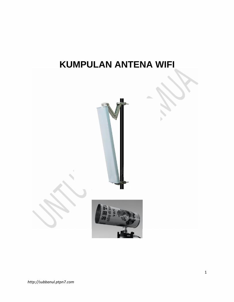
KUMPULAN ANTENA WIFI
2
http://subbanul.ptpn7.com
I. ANTENA KALENG
Alat yang diperlukan
1. Sebuah kaleng yang mempunyai panjang 13,3 cm dan diameter 10 cm (kaleng
pelumas, kaleng susu dll
2. PCMCIA Card (bila anda menggunakan laptop yang belum dilengkapi
perangkat Wi-Fi 802,11b atau 802,11g) yang mempunyai antena luar.
3. PCI W-Lan Card Wi-Fi 802,11b atau 802,11g (untuk anda yang menggunakan
PC, card tersebut ditancapkan ke Slot PCI).
4. Konektor SMA (untuk konektor yg menghubungkan kabel dengan Card
PCMCIA atau PCI W-lan card, biasanya beberapa jenis PCMCIA
masih menggunakan model pigtail dengan konektor SMA, SMB, SMC atau
5. Kabel coaxial RG-58 yang panjangnya sebaiknya tidak lebih dari 15 meter.
6. Konektor N Plug (TNC Plug Connector RG 58 CRMPG) yang digunakan un-
tuk menghubungkan ke kabel.
7. Konektor N (TNC Connector segel chasis).
8. Baut dan mur (untuk menempelkan konektor N ke Antena kaleng).
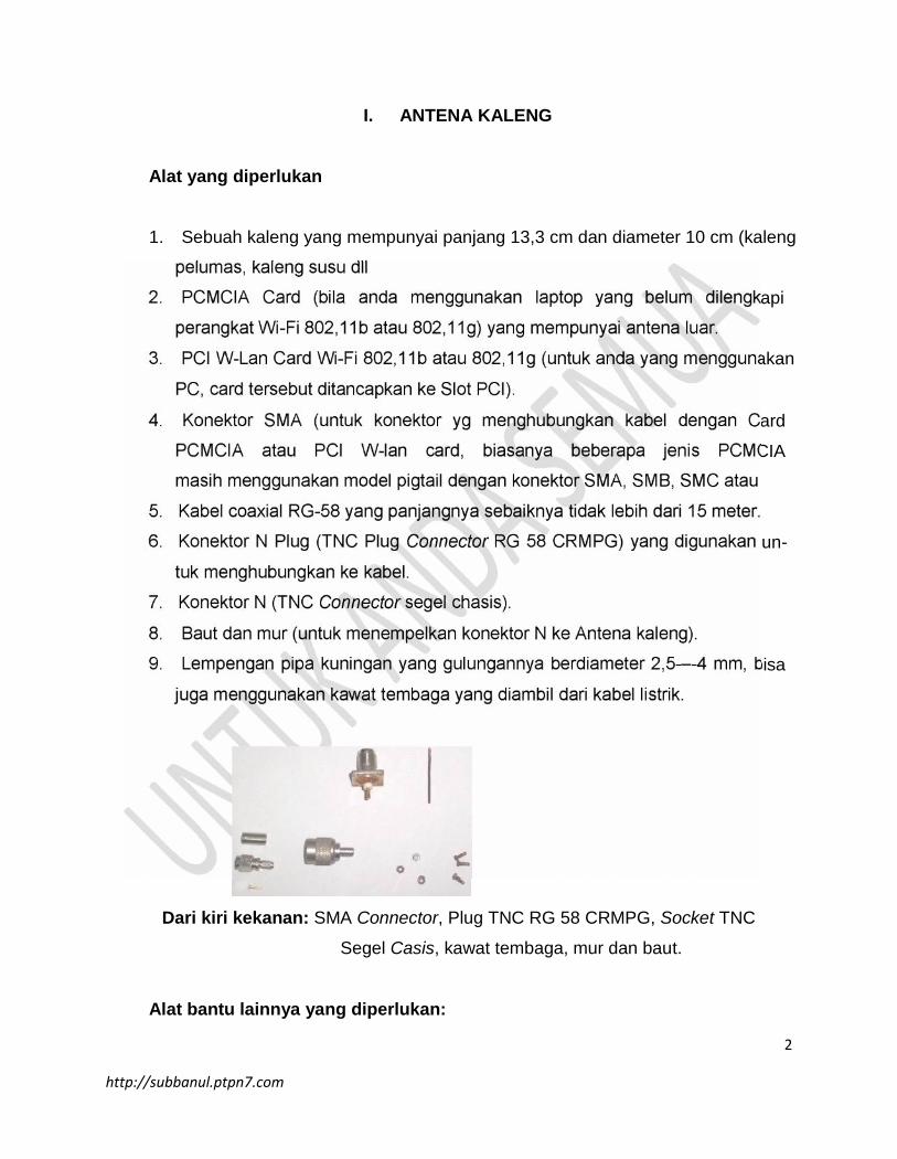
9. Lempengan pipa kuningan yang gulungannya berdiameter 2,5-–-4 mm, bisa
juga menggunakan kawat tembaga yang diambil dari kabel listrik.
Dari kiri kekanan: SMA Connector, Plug TNC RG 58 CRMPG, Socket TNC
Segel Casis, kawat tembaga, mur dan baut.
Alat bantu lainnya yang diperlukan:
3
http://subbanul.ptpn7.com
1. Gergaji besi atau pisau untuk memotong kaleng yang terlalu panjang.
2. Mistar (penggaris) untuk mengukur panjang dan lebar kaleng.
3. Lakban (perekat) untuk merekatkan konektor dengan kabel.
4. Tang (penjepit) untuk mengencangkan mur dengan baut.
5. Obeng (pengencang) untuk memasang kartu dengan motherboard.
Kenali lebih dekat
Untuk lebih memudahkan dalam membeli konektor dan supaya tidak salah
pilih (maklum harga agak mahal) maka gambar diatas di potong-potong.
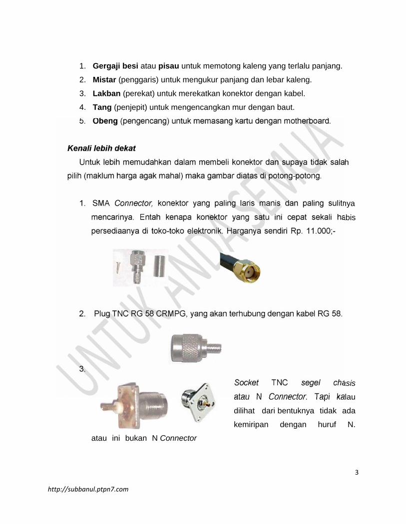
1. SMA Connector, konektor yang paling laris manis dan paling sulitnya
mencarinya. Entah kenapa konektor yang satu ini cepat sekali habis
persediaanya di toko-toko elektronik. Harganya sendiri Rp. 11.000;-
2. Plug TNC RG 58 CRMPG, yang akan terhubung dengan kabel RG 58.
3.
Socket TNC segel chasis
atau N Connector. Tapi kalau
dilihat dari bentuknya tidak ada
kemiripan dengan huruf N.
atau ini bukan N Connector
4
http://subbanul.ptpn7.com
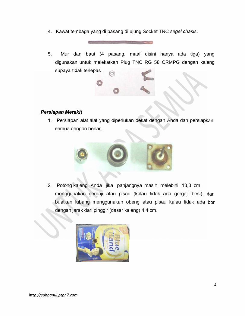
4. Kawat tembaga yang di pasang di ujung Socket TNC segel chasis.
5. Mur dan baut (4 pasang, maaf disini hanya ada tiga) yang
digunakan untuk melekatkan Plug TNC RG 58 CRMPG dengan kaleng
supaya tidak terlepas.
Persiapan Merakit
1. Persiapan alat-alat yang diperlukan dekat dengan Anda dan persiapkan
semua dengan benar.
2. Potong kaleng Anda jika panjangnya masih melebihi 13,3 cm
menggunakan gergaji atau pisau (kalau tidak ada gergaji besi), dan
buatkan lubang menggunakan obeng atau pisau kalau tidak ada bor
dengan jarak dari pinggir (dasar kaleng) 4,4 cm.
5
http://subbanul.ptpn7.com
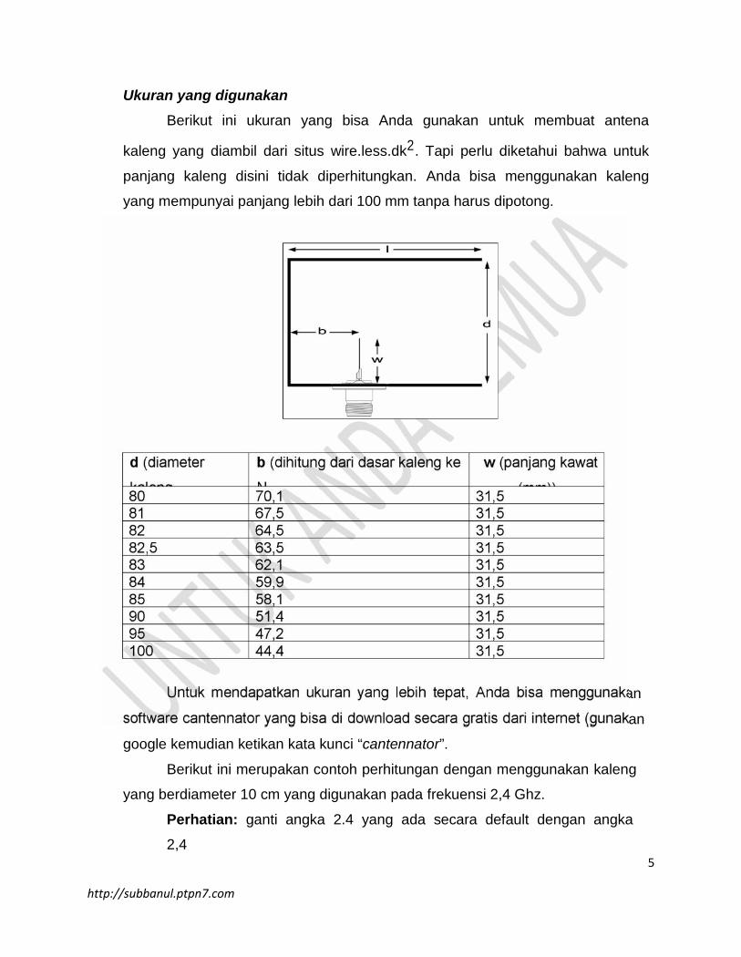
Ukuran yang digunakan
Berikut ini ukuran yang bisa Anda gunakan untuk membuat antena
kaleng yang diambil dari situs wire.less.dk2. Tapi perlu diketahui bahwa untuk
panjang kaleng disini tidak diperhitungkan. Anda bisa menggunakan kaleng
yang mempunyai panjang lebih dari 100 mm tanpa harus dipotong.
d (diameter
kaleng
(mm))
b (dihitung dari dasar kaleng ke
N
konektor (milimeter))
w (panjang kawat
(mm))80 70,1 31,581 67,5 31,582 64,5 31,582,5 63,5 31,583 62,1 31,584 59,9 31,585 58,1 31,590 51,4 31,595 47,2 31,5100 44,4 31,5
Untuk mendapatkan ukuran yang lebih tepat, Anda bisa menggunakan
software cantennator yang bisa di download secara gratis dari internet (gunakan
google kemudian ketikan kata kunci “cantennator”.
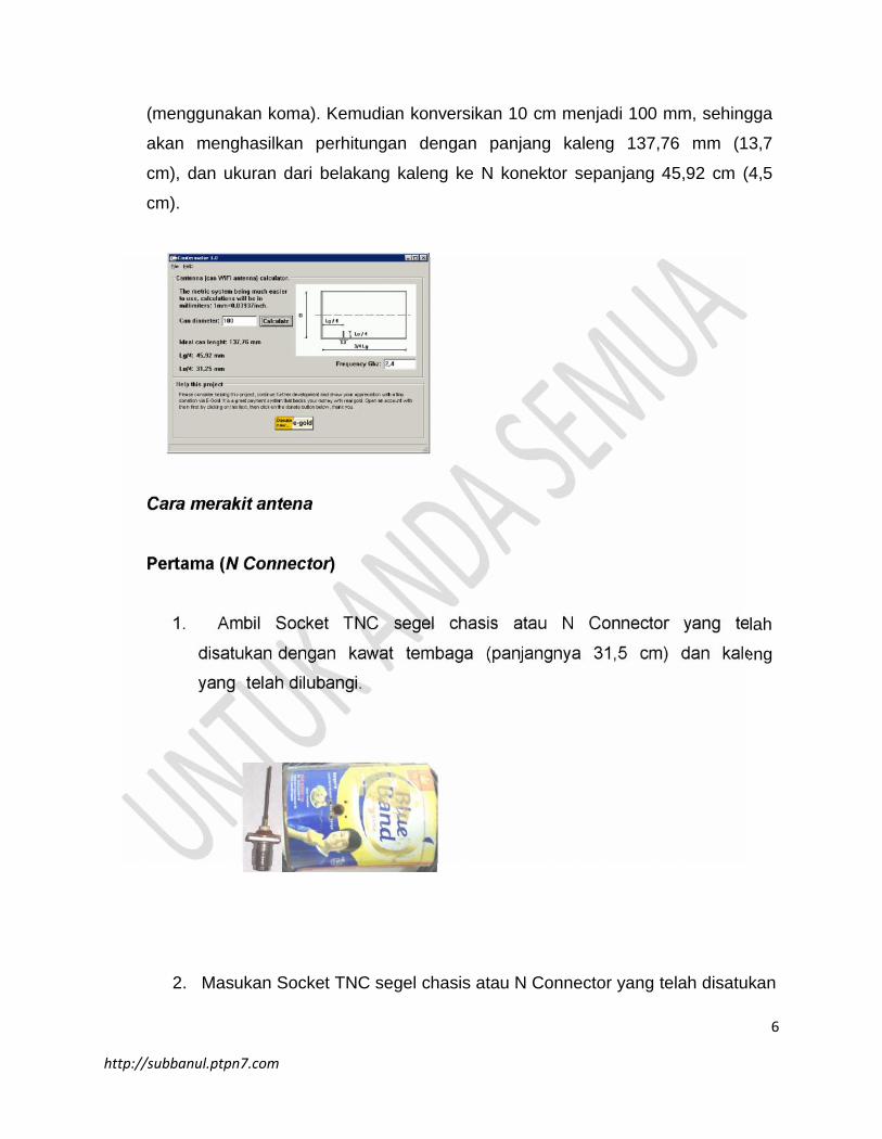
Berikut ini merupakan contoh perhitungan dengan menggunakan kaleng
yang berdiameter 10 cm yang digunakan pada frekuensi 2,4 Ghz.
Perhatian: ganti angka 2.4 yang ada secara default dengan angka
2,4
6
http://subbanul.ptpn7.com
(menggunakan koma). Kemudian konversikan 10 cm menjadi 100 mm, sehingga
akan menghasilkan perhitungan dengan panjang kaleng 137,76 mm (13,7
cm), dan ukuran dari belakang kaleng ke N konektor sepanjang 45,92 cm (4,5
cm).
Cara merakit antena
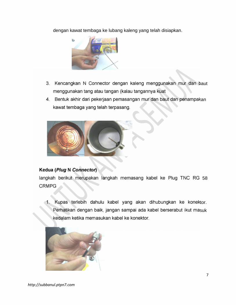
Pertama (N Connector)
1. Ambil Socket TNC segel chasis atau N Connector yang telah
disatukan dengan kawat tembaga (panjangnya 31,5 cm) dan kaleng
yang telah dilubangi.
2. Masukan Socket TNC segel chasis atau N Connector yang telah disatukan
7
http://subbanul.ptpn7.com
dengan kawat tembaga ke lubang kaleng yang telah disiapkan.
3. Kencangkan N Connector dengan kaleng menggunakan mur dan baut
menggunakan tang atau tangan (kalau tangannya kuat
4. Bentuk akhir dari pekerjaan pemasangan mur dan baut dan penampakan
kawat tembaga yang telah terpasang.
Kedua (Plug N Connector)langkah berikut merupakan langkah memasang kabel ke Plug TNC RG 58
CRMPG
1. Kupas terlebih dahulu kabel yang akan dihubungkan ke konektor.
Perhatikan dengan baik, jangan sampai ada kabel berserabut ikut masuk
kedalam ketika memasukan kabel ke konektor.
8
http://subbanul.ptpn7.com
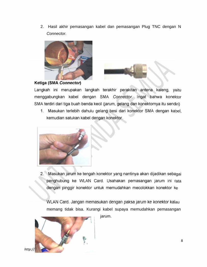
2. Hasil akhir pemasangan kabel dan pemasangan Plug TNC dengan N
Connector.
Ketiga (SMA Connector)Langkah ini merupakan langkah terakhir perakitan antena kaleng, yaitu
menggabungkan kabel dengan SMA Connector. Ingat bahwa konektor
SMA terdiri dari tiga buah benda kecil (jarum, gelang dan konektornya itu sendiri)
1. Masukan terlebih dahulu gelang besi dari konektor SMA dengan kabel,
kemudian satukan kabel dengan konektor.
2. Masukan jarum ke tengah konektor yang nantinya akan dijadikan sebagai
penghubung ke WLAN Card. Usahakan pemasangan jarum ini rata
dengan pinggir konektor untuk memudahkan mecolokkan konektor ke
WLAN Card. Jangan memasukan dengan paksa jarum ke konektor kalau
memang tidak bisa. Kurangi kabel supaya memudahkan pemasangan
jarum.
9
http://subbanul.ptpn7.com
Perhatian:Hati-hati ketika menekan jarum, karena dapat melukai jari-jemari Anda yang
halus atau jarumnya yang patah.
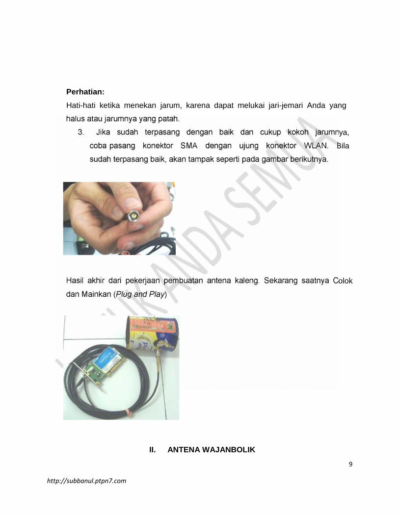
3. Jika sudah terpasang dengan baik dan cukup kokoh jarumnya,
coba pasang konektor SMA dengan ujung konektor WLAN. Bila
sudah terpasang baik, akan tampak seperti pada gambar berikutnya.
Hasil akhir dari pekerjaan pembuatan antena kaleng. Sekarang saatnya Colok
dan Mainkan (Plug and Play)
II. ANTENA WAJANBOLIK
10
http://subbanul.ptpn7.com
Persiapan
Peralatan dan bahan yang perlu di siapkan:
BAHAN
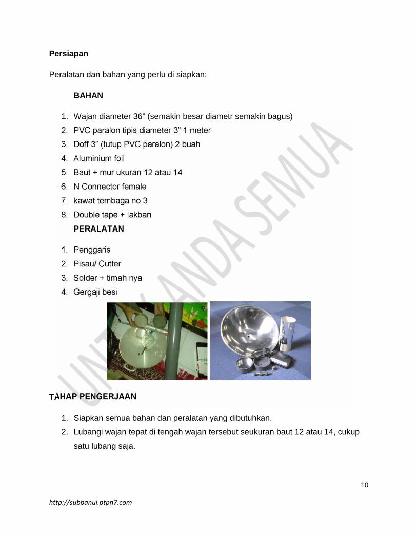
1. Wajan diameter 36” (semakin besar diametr semakin bagus)
2. PVC paralon tipis diameter 3” 1 meter
3. Doff 3” (tutup PVC paralon) 2 buah
4. Aluminium foil
5. Baut + mur ukuran 12 atau 14
6. N Connector female
7. kawat tembaga no.3
8. Double tape + lakban
PERALATAN
1. Penggaris
2. Pisau/ Cutter
3. Solder + timah nya
4. Gergaji besi
TAHAP PENGERJAAN
1. Siapkan semua bahan dan peralatan yang dibutuhkan.
2. Lubangi wajan tepat di tengah wajan tersebut seukuran baut 12 atau 14, cukup
satu lubang saja.
11
http://subbanul.ptpn7.com
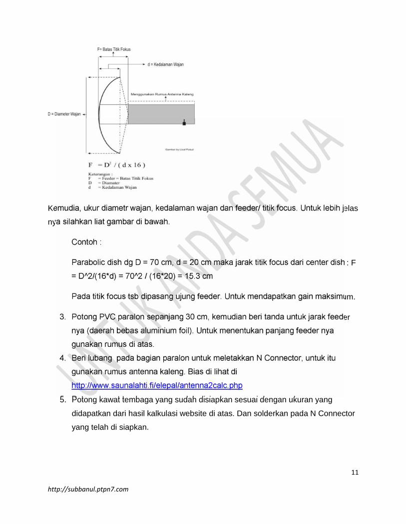
Kemudia, ukur diametr wajan, kedalaman wajan dan feeder/ titik focus. Untuk lebih jelas
nya silahkan liat gambar di bawah.
Contoh :
Parabolic dish dg D = 70 cm, d = 20 cm maka jarak titik focus dari center dish : F
= D^2/(16*d) = 70^2 / (16*20) = 15.3 cm
Pada titik focus tsb dipasang ujung feeder. Untuk mendapatkan gain maksimum.
3. Potong PVC paralon sepanjang 30 cm, kemudian beri tanda untuk jarak feeder
nya (daerah bebas aluminium foil). Untuk menentukan panjang feeder nya
gunakan rumus di atas.
4. Beri lubang pada bagian paralon untuk meletakkan N Connector, untuk itu
gunakan rumus antenna kaleng. Bias di lihat di
http://www.saunalahti.fi/elepal/antenna2calc.php
5. Potong kawat tembaga yang sudah disiapkan sesuai dengan ukuran yang
didapatkan dari hasil kalkulasi website di atas. Dan solderkan pada N Connector
yang telah di siapkan.
12
http://subbanul.ptpn7.com
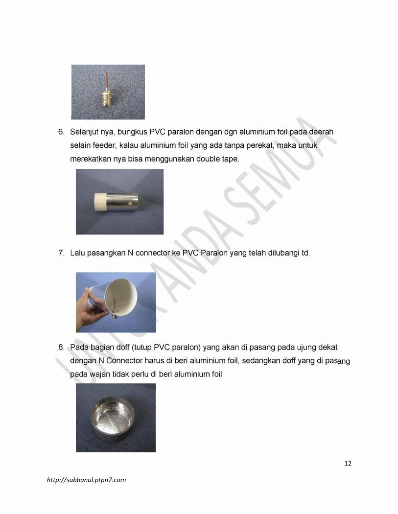
6. Selanjut nya, bungkus PVC paralon dengan dgn aluminium foil pada daerah
selain feeder, kalau aluminium foil yang ada tanpa perekat, maka untuk
merekatkan nya bisa menggunakan double tape.
7. Lalu pasangkan N connector ke PVC Paralon yang telah dilubangi td.
8. Pada bagian doff (tutup PVC paralon) yang akan di pasang pada ujung dekat
dengan N Connector harus di beri aluminium foil, sedangkan doff yang di pasang
pada wajan tidak perlu di beri aluminium foil
13
http://subbanul.ptpn7.com
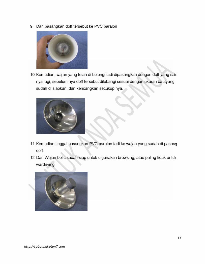
9. Dan pasangkan doff tersebut ke PVC paralon
10.Kemudian, wajan yang telah di bolongi tadi dipasangkan dengan doff yang satu
nya lagi, sebelum nya doff tersebut dilubangi sesuai dengan ukuran bautyang
sudah di siapkan, dan kencangkan secukup nya.
11.Kemudian tinggal pasangkan PVC paralon tadi ke wajan yang sudah di pasang
doff.
12.Dan Wajan bolic sudah siap untuk digunakan browsing, atau paling tidak untuk
wardriving.
14
http://subbanul.ptpn7.com
III. ANTENA HELIKAL.
Komponen yang perlu disiapkan antara lain adalah:
1 x 0.55 meter pipa pralon diameter 40 mm (40 mm inner, 42-43 mm outer).
1 x 40 mm (diameter) penutup pralon.
1 x 150 mm (diameter) penutup pralon atau potongan plastik / kayu yang tenbal
dengan diameter yang sama.
2 x 25 mm atau 35 mm baut U.
8 x mur untuk baut U.
8 x ring untuk baut U.
1 x 5/16” baut (yang pendek) dengar mur & ring yang cocok.
1 x lempengan kuningan dengan ketebalan 0.4-0.7 mm secukupnya untuk
dipotong dengan lingkaran berdiameter 130 mm.
Kabel tembaga diamter 1 mm berlapis email sepanjang beberapa meter.
1 x konektor N untuk di letakan di panel.
3 x mur & ring untuk konektor N tersebut.
Lem Araldite yang lambat mengeringnya.
Lem Loctite 424 atau yang mirip (seperti superglue atau hotglue gun).
Penutup silicon.
Selotape.
Peralatan yang dibutuhkan:
Gergaji.
Meja yang rata / datar.
Pemotong kabel.
Kunci untuk baut 5/16”.
Obeng untuk konektor N.
Bor dan Solder
Gunting (untuk menggunting lempeng kuningan).
Pisau.
15
http://subbanul.ptpn7.com
Langkah membuat antenna tersebut adalah:
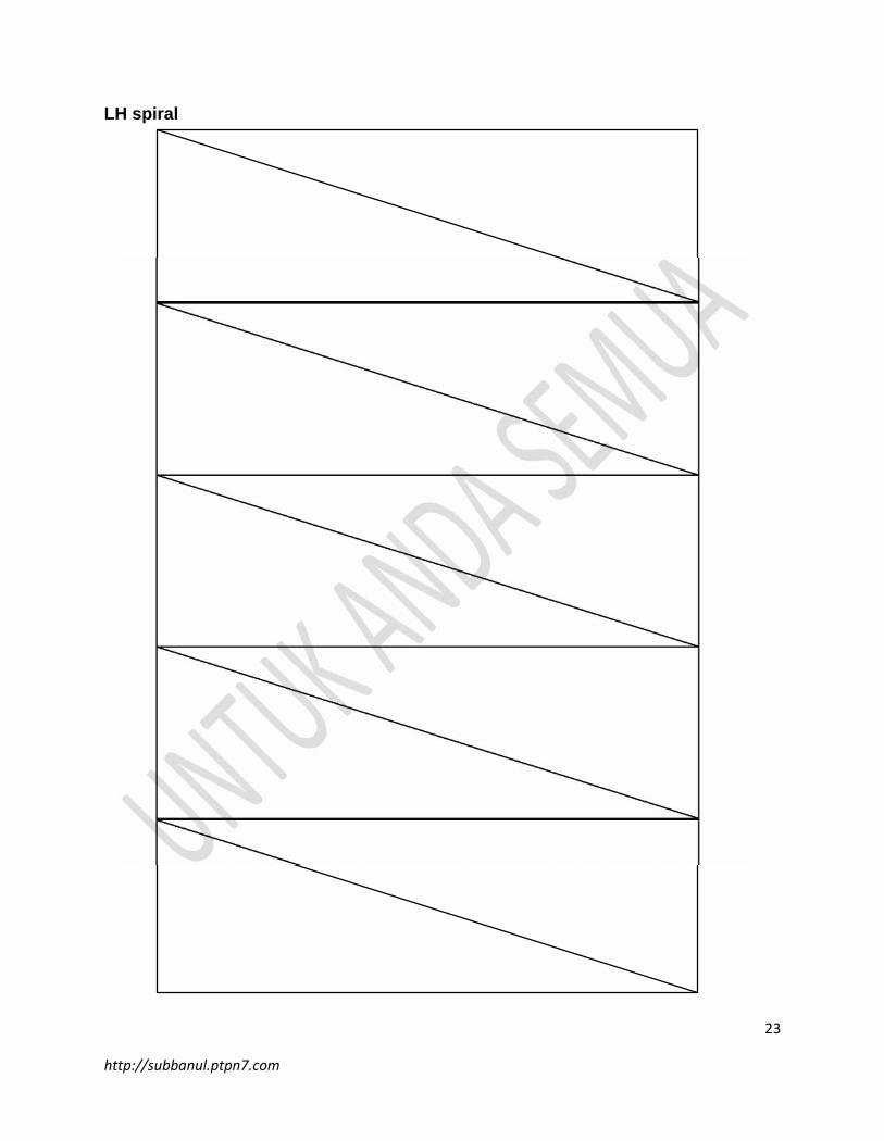
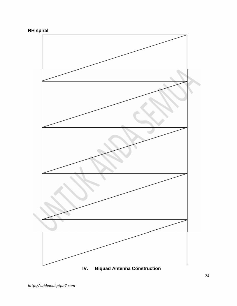
Print & potong template rhspiral. atau lhspiral.pada halaman 19/20. Gunakan
rhspiral untuk right handed spiral helicals dan lhspiral untuk left handed spirals.
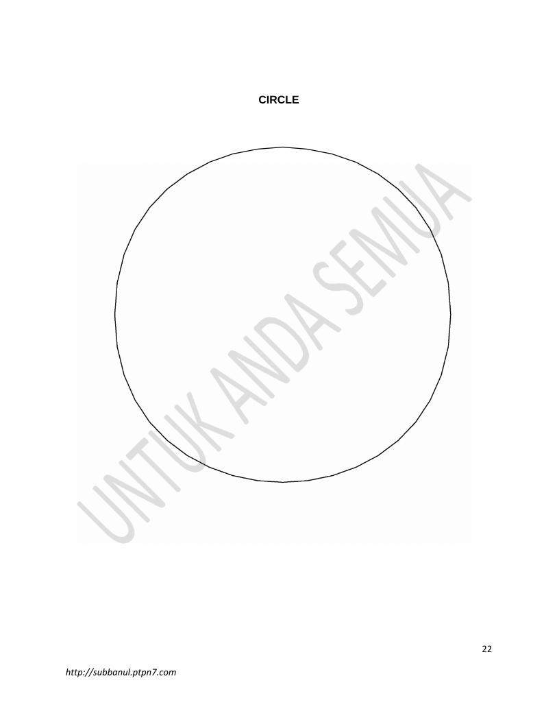
Anda membutuhkan circle untuk membuat ground plane (reflector) pada
halaman 18, kecuali jika anda dapat membuat lingkaran dengan diamter 130 mm
yang baik.
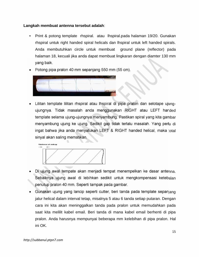
Potong pipa pralon 40 mm sepanjang 550 mm (55 cm).
Lilitan template lilitan rhspiral atau lhspiral di pipa pralon dan selotape ujung-
ujungnya. Tidak masalah anda menggunakan RIGHT atau LEFT handed
template selama ujung-ujungnya menyambung. Pastikan spiral yang kita gambar
menyambung ujung ke ujung. Sedikit gap tidak terlalu masalah. Yang perlu di
ingat bahwa jika anda menyatukan LEFT & RIGHT handed helical, maka total
sinyal akan saling mematikan.
Di ujung awal tempate akan menjadi tempat menempelkan ke dasar antenna.
Sebaiknya ujung awal di lebihkan sedikit untuk mengkompensasi ketebalan
penutup pralon 40 mm. Seperti tampak pada gambar.
Gunakan ujung yang lancip seperti cutter, beri tanda pada template sepanjang
jalur helical dalam interval tetap, misalnya 5 atau 6 tanda setiap putaran. Dengan
cara ini kita akan meninggalkan tanda pada pralon untuk memudahkan pada
saat kita melilit kabel email. Beri tanda di mana kabel email berhenti di pipa
pralon. Anda harusnya mempunyai beberapa mm kelebihan di pipa pralon. Hal
ini OK.
16
http://subbanul.ptpn7.com
Lilitan kabel tembaga berlapis email dan gunakan superglue atau Loctite 424
untuk menempelkan kabel ke tempat akhir kabel di pipa pralon. Perlahan lilitkan
kabel sepanjang pipa pralon ikuti tanda spiral yang telah kita toreh di pipa pralon.
Pada interval yang sama, misalnya setiap ½ atau 1/3 lilit, tambahkan lem untuk
menempelkan kabel di tempatnya.
Pada saat anda mendekati akhir lilitan, lilitan terakhir jangan di lem. Biarkan
cukup banyak kabel (10 cm atau lebih) di akhir lilitan. Biarkan dulu beberapa saat
sampai lem mengering.
Potong lempengan kuningan atau tembaha dengan diameter 130 mm diambil
dari circle.pdf.
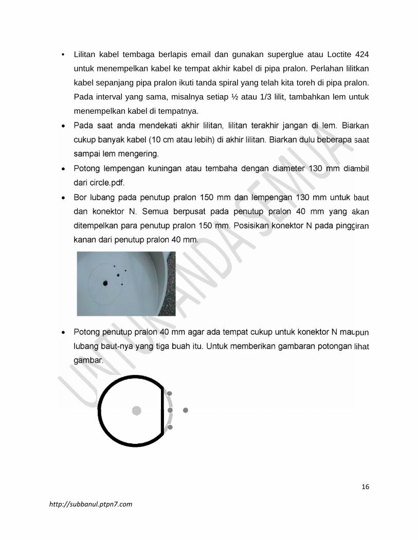
Bor lubang pada penutup pralon 150 mm dan lempengan 130 mm untuk baut
dan konektor N. Semua berpusat pada penutup pralon 40 mm yang akan
ditempelkan para penutup pralon 150 mm. Posisikan konektor N pada pinggiran
kanan dari penutup pralon 40 mm.
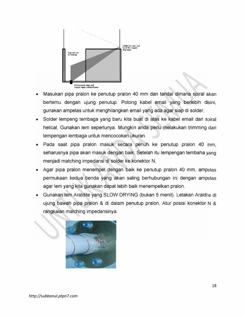
Potong penutup pralon 40 mm agar ada tempat cukup untuk konektor N maupun
lubang baut-nya yang tiga buah itu. Untuk memberikan gambaran potongan lihat
gambar.
17
http://subbanul.ptpn7.com
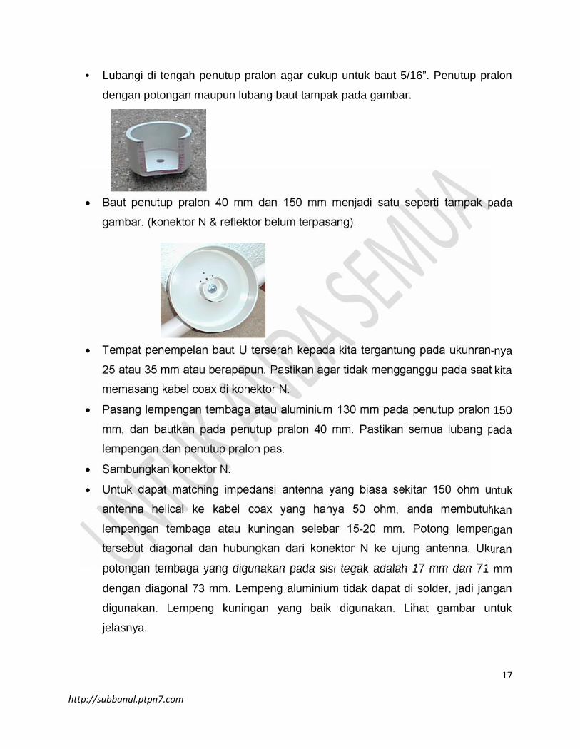
Lubangi di tengah penutup pralon agar cukup untuk baut 5/16”. Penutup pralon
dengan potongan maupun lubang baut tampak pada gambar.
Baut penutup pralon 40 mm dan 150 mm menjadi satu seperti tampak pada
gambar. (konektor N & reflektor belum terpasang).
Tempat penempelan baut U terserah kepada kita tergantung pada ukunran-nya
25 atau 35 mm atau berapapun. Pastikan agar tidak mengganggu pada saat kita
memasang kabel coax di konektor N.
Pasang lempengan tembaga atau aluminium 130 mm pada penutup pralon 150
mm, dan bautkan pada penutup pralon 40 mm. Pastikan semua lubang pada
lempengan dan penutup pralon pas.
Sambungkan konektor N.
Untuk dapat matching impedansi antenna yang biasa sekitar 150 ohm untuk
antenna helical ke kabel coax yang hanya 50 ohm, anda membutuhkan
lempengan tembaga atau kuningan selebar 15-20 mm. Potong lempengan
tersebut diagonal dan hubungkan dari konektor N ke ujung antenna. Ukuran
potongan tembaga yang digunakan pada sisi tegak adalah 17 mm dan 71 mm
dengan diagonal 73 mm. Lempeng aluminium tidak dapat di solder, jadi jangan
digunakan. Lempeng kuningan yang baik digunakan. Lihat gambar untuk
jelasnya.
18
http://subbanul.ptpn7.com
Masukan pipa pralon ke penutup pralon 40 mm dan tandai dimana spiral akan
bertemu dengan ujung penutup. Potong kabel email yang berlebih disini,
gunakan ampelas untuk menghilangkan email yang ada agar siap di solder.
Solder lempeng tembaga yang baru kita buat di atas ke kabel email dari spiral
helical. Gunakan lem seperlunya. Mungkin anda perlu melakukan trimming dari
lempengan lembaga untuk mencocokan ukuran.
Pada saat pipa pralon masuk secara penuh ke penutup pralon 40 mm,
seharusnya pipa akan masuk dengan baik. Setelah itu lempengan tembaha yang
menjadi matching impedansi di solder ke konektor N.
Agar pipa pralon menempel dengan baik ke penutup pralon 40 mm, ampelas
permukaan kedua benda yang akan saling berhubungan ini dengan ampelas
agar lem yang kita gunakan dapat lebih baik menempelkan pralon.
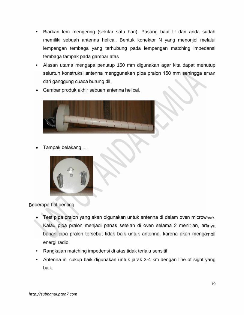
Gunakan lem Araldite yang SLOW DRYING (bukan 5 menit). Letakan Araldite di
ujung bawah pipa pralon & di dalam penutup pralon. Atur posisi konektor N &
rangkaian matching impedansinya.
19
http://subbanul.ptpn7.com
Biarkan lem mengering (sekitar satu hari). Pasang baut U dan anda sudah
memiliki sebuah antenna helical. Bentuk konektor N yang menonjol melalui
lempengan tembaga yang terhubung pada lempengan matching impedansi
tembaga tampak pada gambar.atas
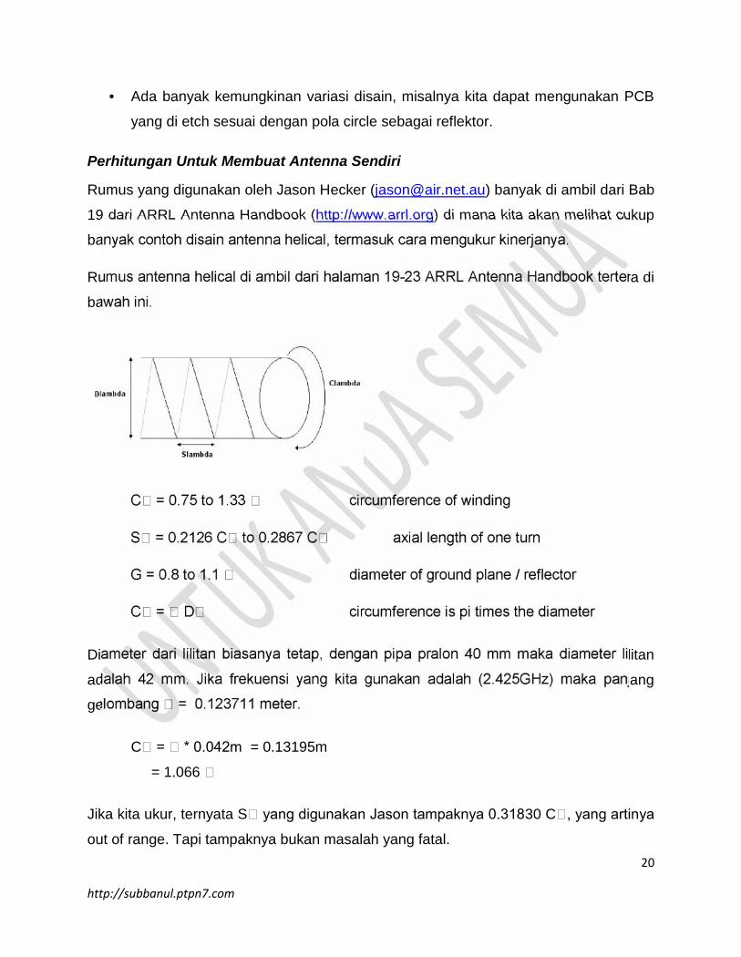
Alasan utama mengapa penutup 150 mm digunakan agar kita dapat menutup
selurtuh konstruksi antenna menggunakan pipa pralon 150 mm sehingga aman
dari ganggung cuaca burung dll.
Gambar produk akhir sebuah antenna helical.
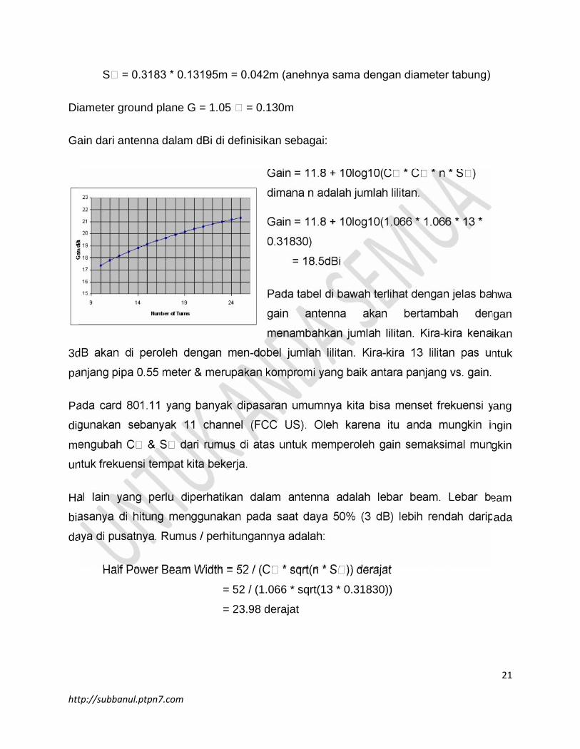
Tampak belakang ....
Beberapa hal penting
Test pipa pralon yang akan digunakan untuk antenna di dalam oven microwave.
Kalau pipa pralon menjadi panas setelah di oven selama 2 menit-an, artinya
bahan pipa pralon tersebut tidak baik untuk antenna, karena akan mengambil
energi radio.
Rangkaian matching impedensi di atas tidak terlalu sensitif.
Antenna ini cukup baik digunakan untuk jarak 3-4 km dengan line of sight yang
baik.
20
http://subbanul.ptpn7.com
Ada banyak kemungkinan variasi disain, misalnya kita dapat mengunakan PCB
yang di etch sesuai dengan pola circle sebagai reflektor.
Perhitungan Untuk Membuat Antenna Sendiri
Rumus yang digunakan oleh Jason Hecker ([email protected]) banyak di ambil dari Bab
19 dari ARRL Antenna Handbook (http://www.arrl.org) di mana kita akan melihat cukup
banyak contoh disain antenna helical, termasuk cara mengukur kinerjanya.
Rumus antenna helical di ambil dari halaman 19-23 ARRL Antenna Handbook tertera di
bawah ini.
C = 0.75 to 1.33 circumference of winding
S = 0.2126 C to 0.2867 C axial length of one turn
G = 0.8 to 1.1 diameter of ground plane / reflector
C = D circumference is pi times the diameter
Diameter dari lilitan biasanya tetap, dengan pipa pralon 40 mm maka diameter lilitan
adalah 42 mm. Jika frekuensi yang kita gunakan adalah (2.425GHz) maka panjang
gelombang = 0.123711 meter.
C = * 0.042m = 0.13195m
= 1.066
Jika kita ukur, ternyata S yang digunakan Jason tampaknya 0.31830 C , yang artinya
out of range. Tapi tampaknya bukan masalah yang fatal.
21
http://subbanul.ptpn7.com
S = 0.3183 * 0.13195m = 0.042m (anehnya sama dengan diameter tabung)
Diameter ground plane G = 1.05 = 0.130m
Gain dari antenna dalam dBi di definisikan sebagai:
Gain = 11.8 + 10log10(C * C * n * S )
dimana n adalah jumlah lilitan.
Gain = 11.8 + 10log10(1.066 * 1.066 * 13 *
0.31830)
= 18.5dBi
Pada tabel di bawah terlihat dengan jelas bahwa
gain antenna akan bertambah dengan
menambahkan jumlah lilitan. Kira-kira kenaikan
3dB akan di peroleh dengan men-dobel jumlah lilitan. Kira-kira 13 lilitan pas untuk
panjang pipa 0.55 meter & merupakan kompromi yang baik antara panjang vs. gain.
Pada card 801.11 yang banyak dipasaran umumnya kita bisa menset frekuensi yang
digunakan sebanyak 11 channel (FCC US). Oleh karena itu anda mungkin ingin
mengubah C & S dari rumus di atas untuk memperoleh gain semaksimal mungkin
untuk frekuensi tempat kita bekerja.
Hal lain yang perlu diperhatikan dalam antenna adalah lebar beam. Lebar beam
biasanya di hitung menggunakan pada saat daya 50% (3 dB) lebih rendah daripada
daya di pusatnya. Rumus / perhitungannya adalah:
Half Power Beam Width = 52 / (C * sqrt(n * S )) derajat
= 52 / (1.066 * sqrt(13 * 0.31830))
= 23.98 derajat
22
http://subbanul.ptpn7.com
CIRCLE
23
http://subbanul.ptpn7.com
LH spiral
24
http://subbanul.ptpn7.com
RH spiral
IV. Biquad Antenna Construction
25
http://subbanul.ptpn7.com
Parts RequiredI used the following bits and pieces:
123x123mm square section of blank PCB
50mm length of 1/2" copper pipe
short length of CNT-400 or LMR-400 low loss coax (~300mm long)
250mm of 2.5mm2 copper wire (approx 1.5mm diameter)
N connector
Note that you don't have to use blank PCB for the reflector. You can use any material
that's electrically conductive, can be electrically connected to the coax braid, and will
reflect microwaves (ie, any metal plate will do fine).
I've also heard of people using CDROM as the reflector, as the foil on it will certainly
reflect microwaves.
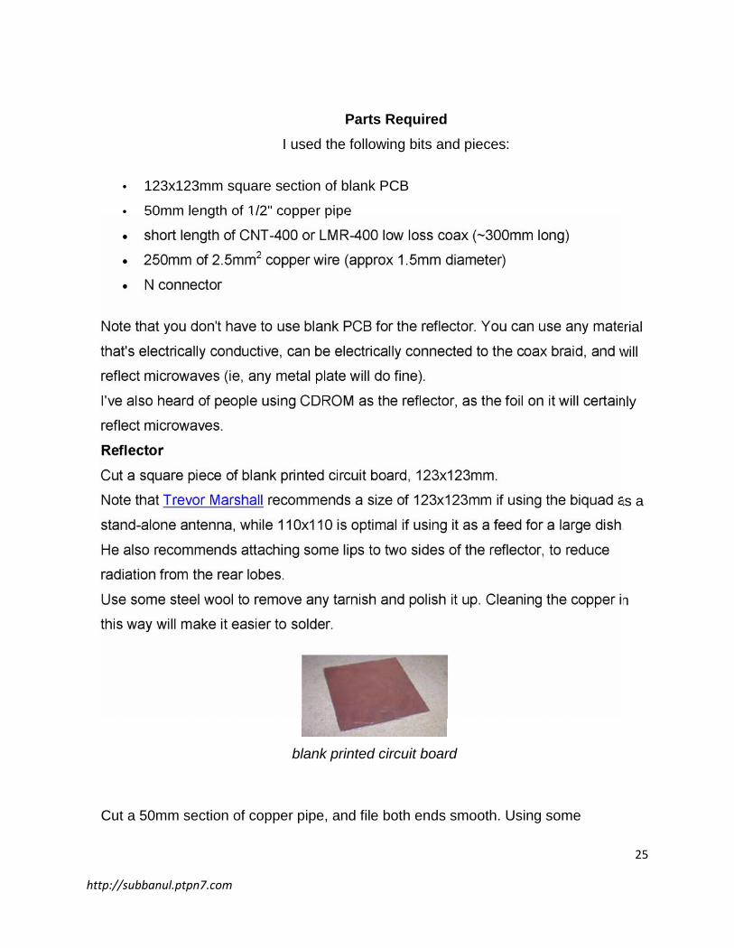
ReflectorCut a square piece of blank printed circuit board, 123x123mm.
Note that Trevor Marshall recommends a size of 123x123mm if using the biquad as a
stand-alone antenna, while 110x110 is optimal if using it as a feed for a large dish.
He also recommends attaching some lips to two sides of the reflector, to reduce
radiation from the rear lobes.
Use some steel wool to remove any tarnish and polish it up. Cleaning the copper in
this way will make it easier to solder.
blank printed circuit board
Cut a 50mm section of copper pipe, and file both ends smooth. Using some
26
http://subbanul.ptpn7.com
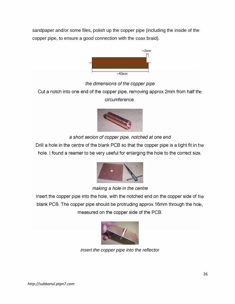
sandpaper and/or some files, polish up the copper pipe (including the inside of the
copper pipe, to ensure a good connection with the coax braid).
the dimensions of the copper pipe
Cut a notch into one end of the copper pipe, removing approx 2mm from half the
circumference.
a short secion of copper pipe, notched at one end
Drill a hole in the centre of the blank PCB so that the copper pipe is a tight fit in the
hole. I found a reamer to be very useful for enlarging the hole to the correct size.
making a hole in the centre
Insert the copper pipe into the hole, with the notched end on the copper side of the
blank PCB. The copper pipe should be protruding approx 16mm through the hole,
measured on the copper side of the PCB.
insert the copper pipe into the reflector
27
http://subbanul.ptpn7.com
Solder the copper pipe to the PCB, to ensure a good physical and electrical
connection.
solder the copper pipe to the PCB
Quite a bit of heat is needed, due to the thickness of the copper pipe, and an
electrical soldering iron probably won't be able to deliver sufficent heat. I found a
small gas torch works quite well.
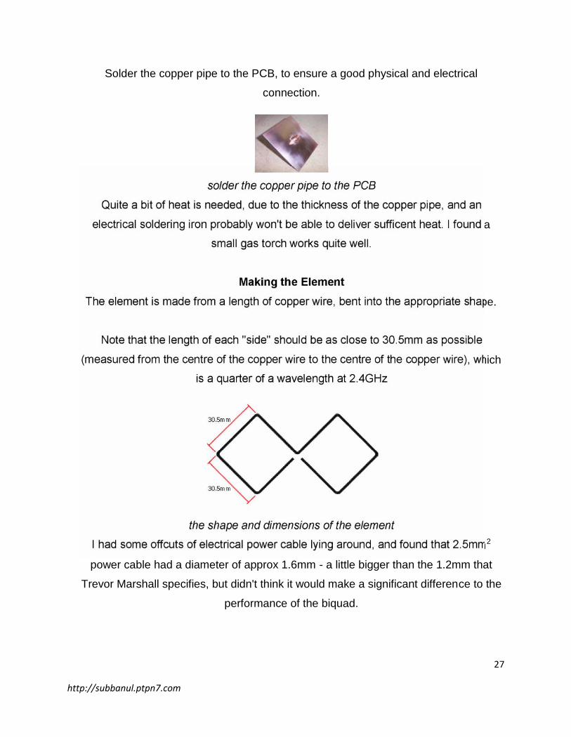
Making the ElementThe element is made from a length of copper wire, bent into the appropriate shape.
Note that the length of each "side" should be as close to 30.5mm as possible
(measured from the centre of the copper wire to the centre of the copper wire), which
is a quarter of a wavelength at 2.4GHz
the shape and dimensions of the element
I had some offcuts of electrical power cable lying around, and found that 2.5mm2
power cable had a diameter of approx 1.6mm - a little bigger than the 1.2mm that
Trevor Marshall specifies, but didn't think it would make a significant difference to the
performance of the biquad.
28
http://subbanul.ptpn7.com
recycling power cable offcuts
Remove the insulation, measure and cut a 244mm length the copper wire, and
straighten it as best as you can.
straighten the wire
Measure the mid-point of the wire, and make a 90 degree bend. The bend should be
quite sharp and pronounced.
90 degree bend
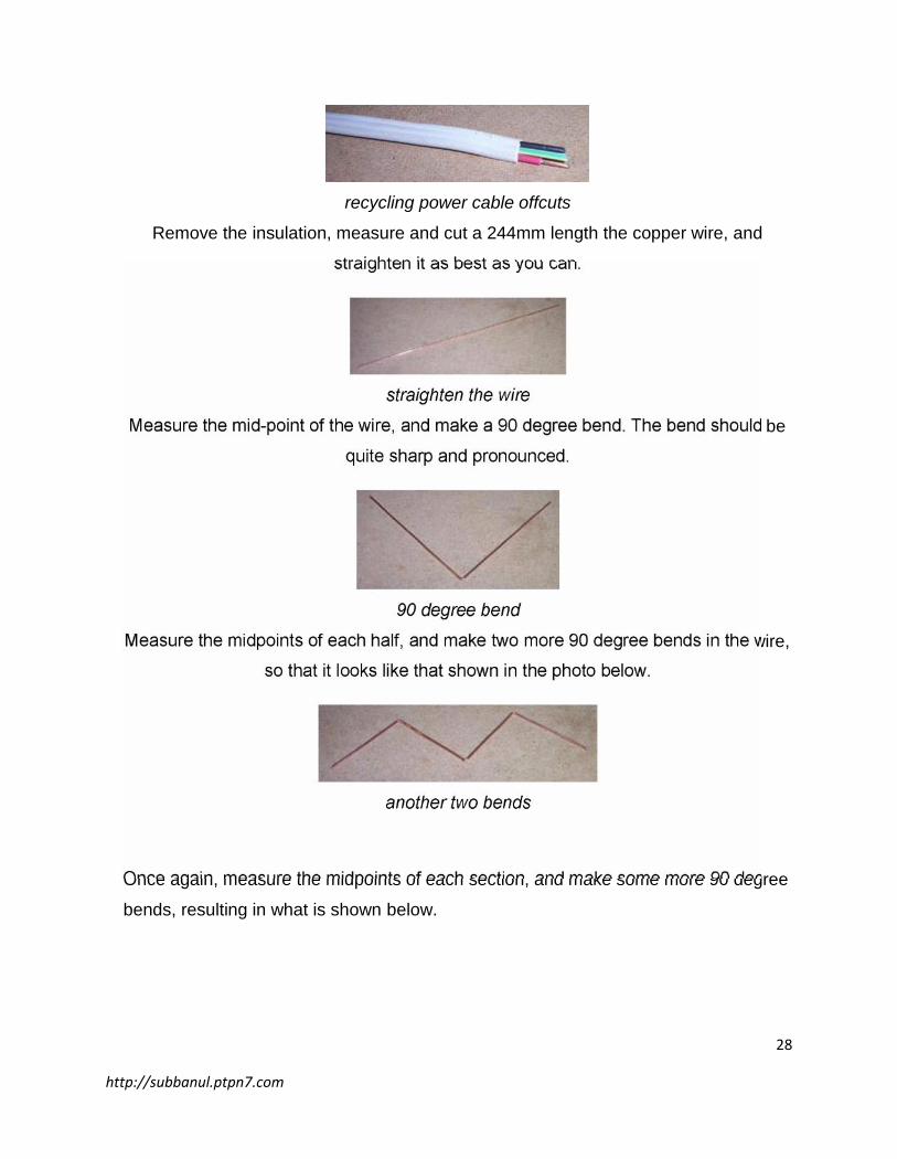
Measure the midpoints of each half, and make two more 90 degree bends in the wire,
so that it looks like that shown in the photo below.
another two bends
Once again, measure the midpoints of each section, and make some more 90 degree
bends, resulting in what is shown below.
29
http://subbanul.ptpn7.com
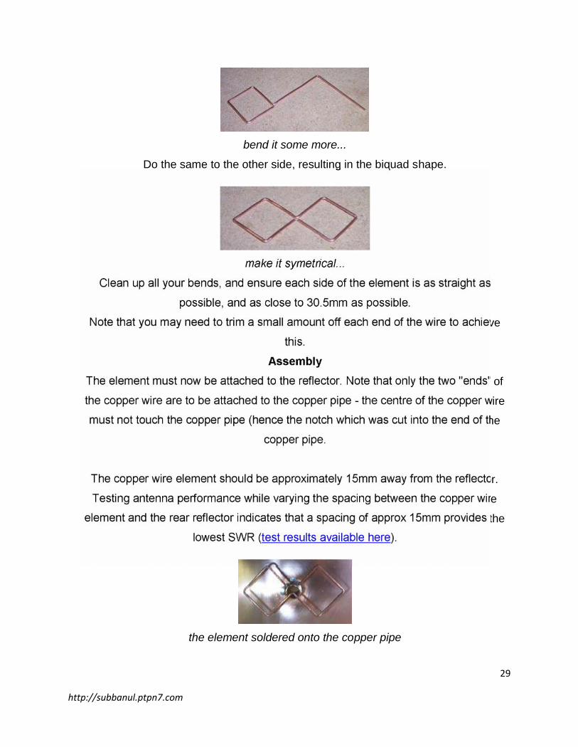
bend it some more...
Do the same to the other side, resulting in the biquad shape.
make it symetrical...
Clean up all your bends, and ensure each side of the element is as straight as
possible, and as close to 30.5mm as possible.
Note that you may need to trim a small amount off each end of the wire to achieve
this.
AssemblyThe element must now be attached to the reflector. Note that only the two "ends" of
the copper wire are to be attached to the copper pipe - the centre of the copper wire
must not touch the copper pipe (hence the notch which was cut into the end of the
copper pipe.
The copper wire element should be approximately 15mm away from the reflector.
Testing antenna performance while varying the spacing between the copper wire
element and the rear reflector indicates that a spacing of approx 15mm provides the
lowest SWR (test results available here).
the element soldered onto the copper pipe
30
http://subbanul.ptpn7.com
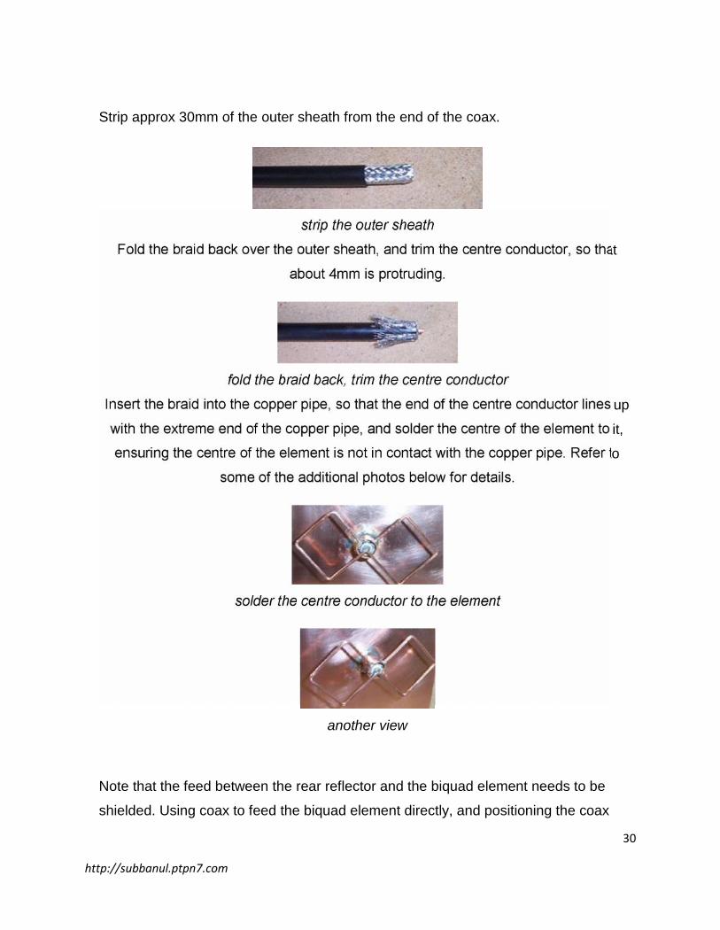
Strip approx 30mm of the outer sheath from the end of the coax.
strip the outer sheath
Fold the braid back over the outer sheath, and trim the centre conductor, so that
about 4mm is protruding.
fold the braid back, trim the centre conductor
Insert the braid into the copper pipe, so that the end of the centre conductor lines up
with the extreme end of the copper pipe, and solder the centre of the element to it,
ensuring the centre of the element is not in contact with the copper pipe. Refer to
some of the additional photos below for details.
solder the centre conductor to the element
another view
Note that the feed between the rear reflector and the biquad element needs to be
shielded. Using coax to feed the biquad element directly, and positioning the coax
31
http://subbanul.ptpn7.com
inside the copper tube achieves this.
Use of bare conductors as a feed between the reflector and biquad element results in
a radiating feed (such as this one), which will have a detrimental effect on the
biquad's performance.
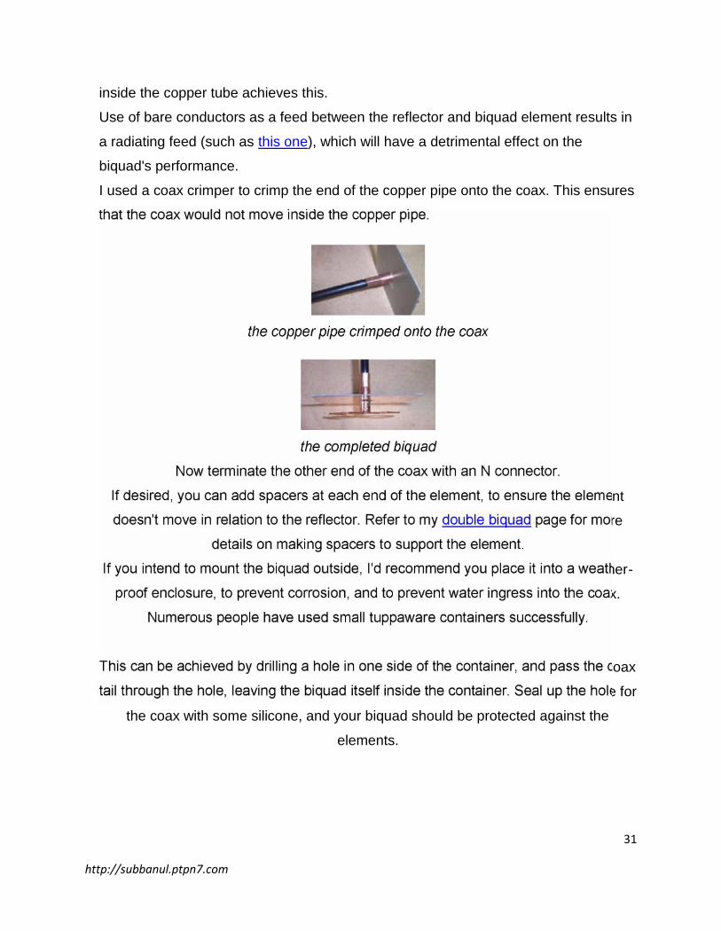
I used a coax crimper to crimp the end of the copper pipe onto the coax. This ensures
that the coax would not move inside the copper pipe.
the copper pipe crimped onto the coax
the completed biquad
Now terminate the other end of the coax with an N connector.
If desired, you can add spacers at each end of the element, to ensure the element
doesn't move in relation to the reflector. Refer to my double biquad page for more
details on making spacers to support the element.
If you intend to mount the biquad outside, I'd recommend you place it into a weather-
proof enclosure, to prevent corrosion, and to prevent water ingress into the coax.
Numerous people have used small tuppaware containers successfully.
This can be achieved by drilling a hole in one side of the container, and pass the coax
tail through the hole, leaving the biquad itself inside the container. Seal up the hole for
the coax with some silicone, and your biquad should be protected against the
elements.
32
http://subbanul.ptpn7.com
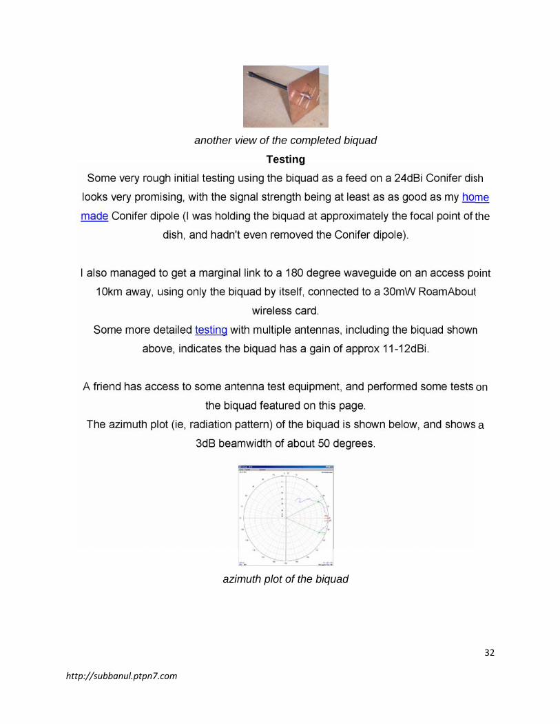
another view of the completed biquad
TestingSome very rough initial testing using the biquad as a feed on a 24dBi Conifer dish
looks very promising, with the signal strength being at least as as good as my home
made Conifer dipole (I was holding the biquad at approximately the focal point of the
dish, and hadn't even removed the Conifer dipole).
I also managed to get a marginal link to a 180 degree waveguide on an access point
10km away, using only the biquad by itself, connected to a 30mW RoamAbout
wireless card.
Some more detailed testing with multiple antennas, including the biquad shown
above, indicates the biquad has a gain of approx 11-12dBi.
A friend has access to some antenna test equipment, and performed some tests on
the biquad featured on this page.
The azimuth plot (ie, radiation pattern) of the biquad is shown below, and shows a
3dB beamwidth of about 50 degrees.
azimuth plot of the biquad
33
http://subbanul.ptpn7.com
VariationsA number of people have suggested the spacing between the element and the rear
reflector should be a 1/4 wavelength (ie, 30.5mm) instead of 15mm. However, test
results (such as these) indicate the SWR of the biquad is minimised when the spacing
is about 15-17mm. Increasing the spacing to 30.5mm increases the SWR
significantly, thus reducing the efficiency of the biquad.
For a higher-gain variation of the biquad that's virtually just as easy to build, have a
look at the double biquad.
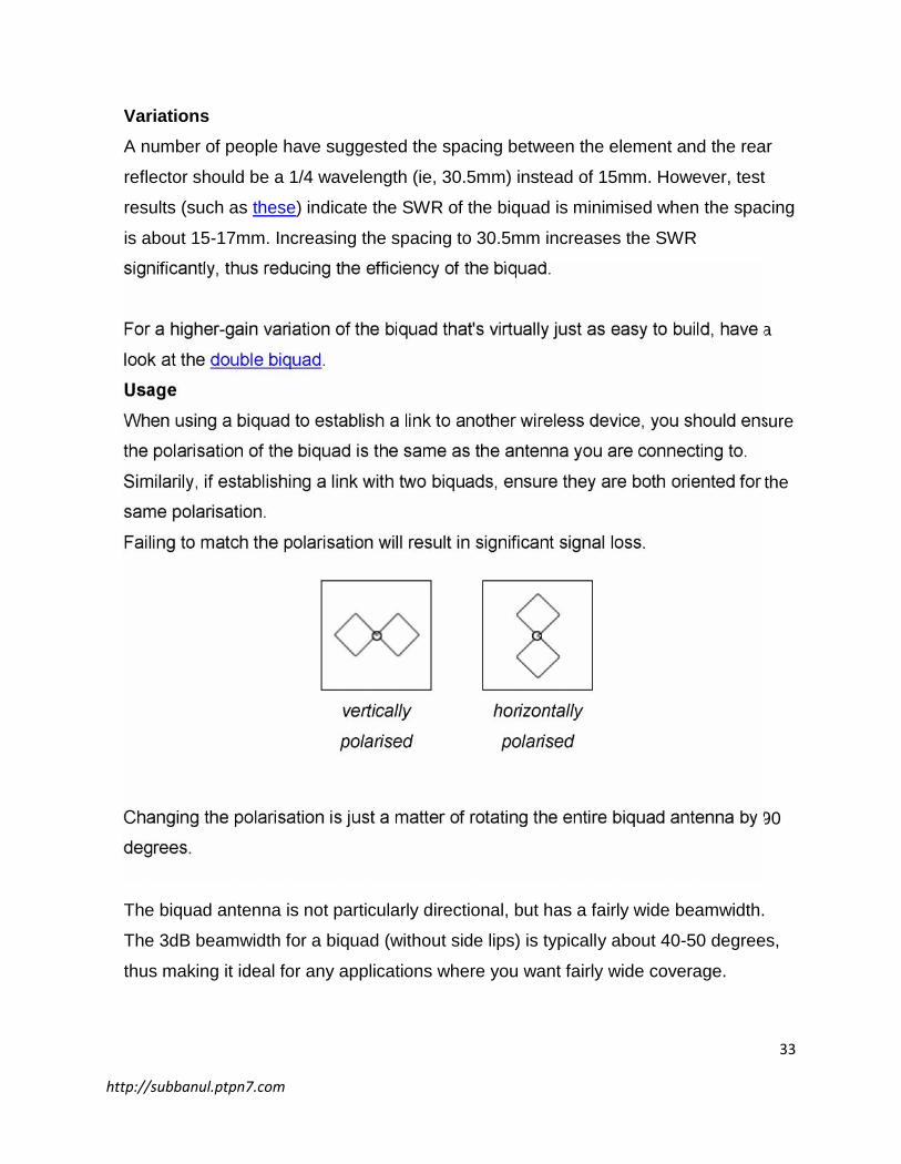
UsageWhen using a biquad to establish a link to another wireless device, you should ensure
the polarisation of the biquad is the same as the antenna you are connecting to.
Similarily, if establishing a link with two biquads, ensure they are both oriented for the
same polarisation.
Failing to match the polarisation will result in significant signal loss.
vertically
polarised
horizontally
polarised
Changing the polarisation is just a matter of rotating the entire biquad antenna by 90
degrees.
The biquad antenna is not particularly directional, but has a fairly wide beamwidth.
The 3dB beamwidth for a biquad (without side lips) is typically about 40-50 degrees,
thus making it ideal for any applications where you want fairly wide coverage.
34
http://subbanul.ptpn7.com
The relatively wide beamwidth also makes a biquad very suitable for war-driving and
stumbling, allowing you to pick up signals without having to align the antenna directly
with the signal source.
While a directional antenna, such as a Conifer dish (3dB beamwidth of a 24dBi
Conifer dish is approx 7 degrees), is better suited for point-to-point links, the narrow
beamwidth of a Conifer dish requires more precision when aligning the antennas (the
narrower the beamwidth, the less susceptible it will be to interferance from other
sources). An antenna with a wider beamwidth, such as a biquad, doesn't require the
same precision for alignment, thus making
Double Biquad Antenna
This page contains details on building a double biquad antenna with approx 13dBi gain.
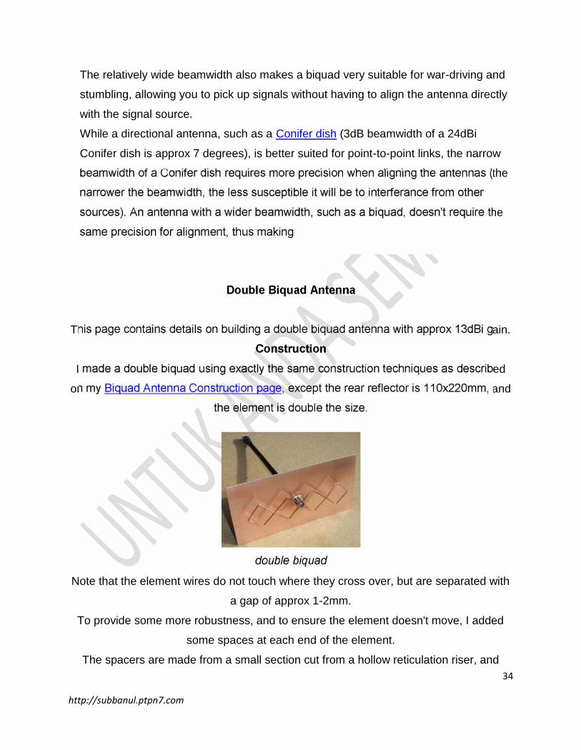
ConstructionI made a double biquad using exactly the same construction techniques as described
on my Biquad Antenna Construction page, except the rear reflector is 110x220mm, and
the element is double the size.
double biquad
Note that the element wires do not touch where they cross over, but are separated with
a gap of approx 1-2mm.
To provide some more robustness, and to ensure the element doesn't move, I added
some spaces at each end of the element.
The spacers are made from a small section cut from a hollow reticulation riser, and
35
http://subbanul.ptpn7.com
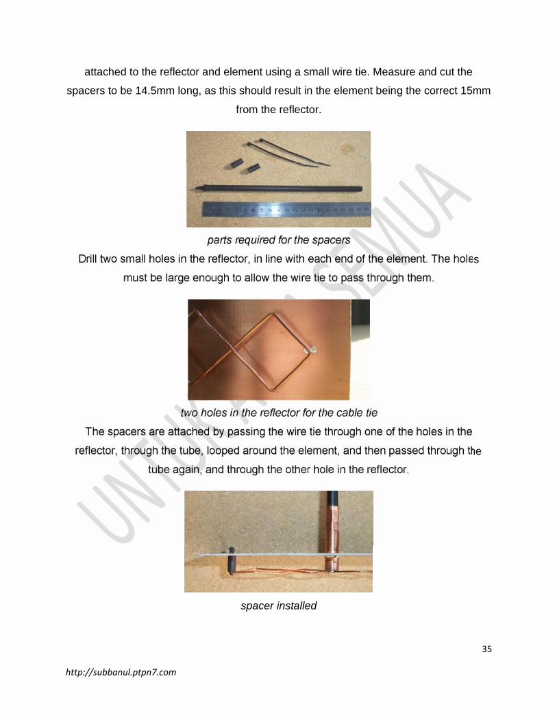
attached to the reflector and element using a small wire tie. Measure and cut the
spacers to be 14.5mm long, as this should result in the element being the correct 15mm
from the reflector.
parts required for the spacers
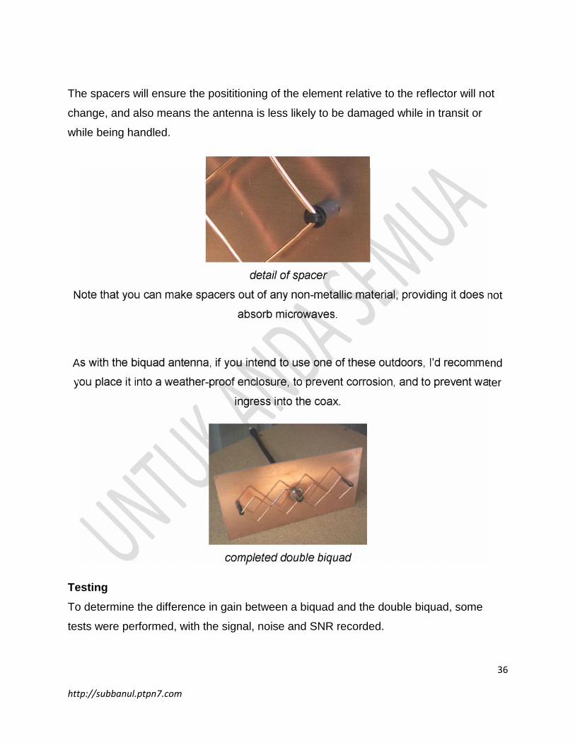
Drill two small holes in the reflector, in line with each end of the element. The holes
must be large enough to allow the wire tie to pass through them.
two holes in the reflector for the cable tie
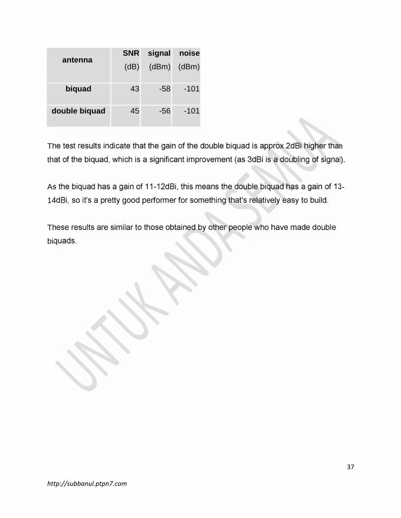
The spacers are attached by passing the wire tie through one of the holes in the
reflector, through the tube, looped around the element, and then passed through the
tube again, and through the other hole in the reflector.
spacer installed
36
http://subbanul.ptpn7.com
The spacers will ensure the posititioning of the element relative to the reflector will not
change, and also means the antenna is less likely to be damaged while in transit or
while being handled.
detail of spacer
Note that you can make spacers out of any non-metallic material, providing it does not
absorb microwaves.
As with the biquad antenna, if you intend to use one of these outdoors, I'd recommend
you place it into a weather-proof enclosure, to prevent corrosion, and to prevent water
ingress into the coax.
completed double biquad
TestingTo determine the difference in gain between a biquad and the double biquad, some
tests were performed, with the signal, noise and SNR recorded.
37
http://subbanul.ptpn7.com
antennaSNR(dB)
signal(dBm)
noise(dBm)
biquad 43 -58 -101
double biquad 45 -56 -101
The test results indicate that the gain of the double biquad is approx 2dBi higher than
that of the biquad, which is a significant improvement (as 3dBi is a doubling of signal).
As the biquad has a gain of 11-12dBi, this means the double biquad has a gain of 13-
14dBi, so it's a pretty good performer for something that's relatively easy to build.
These results are similar to those obtained by other people who have made double
biquads.
38
http://subbanul.ptpn7.com
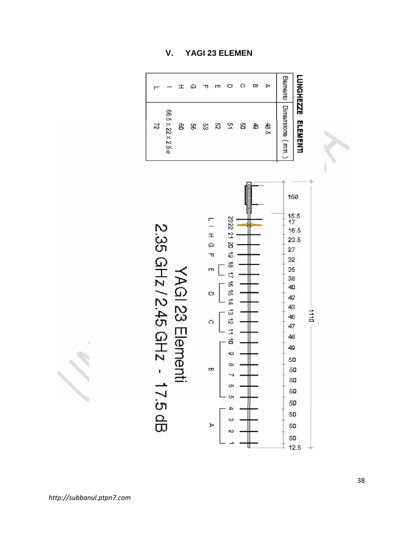
V. YAGI 23 ELEMEN
39
http://subbanul.ptpn7.com
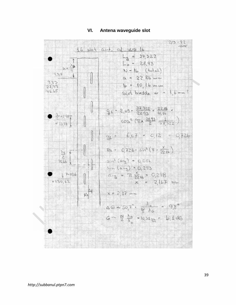
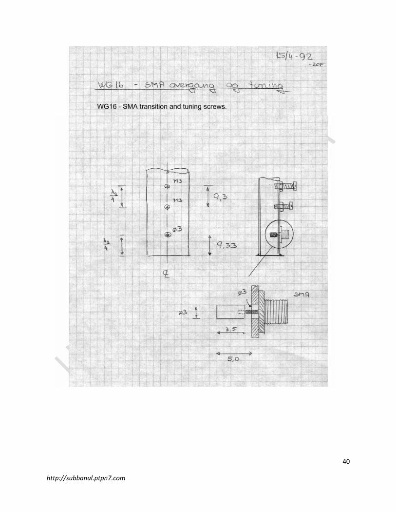
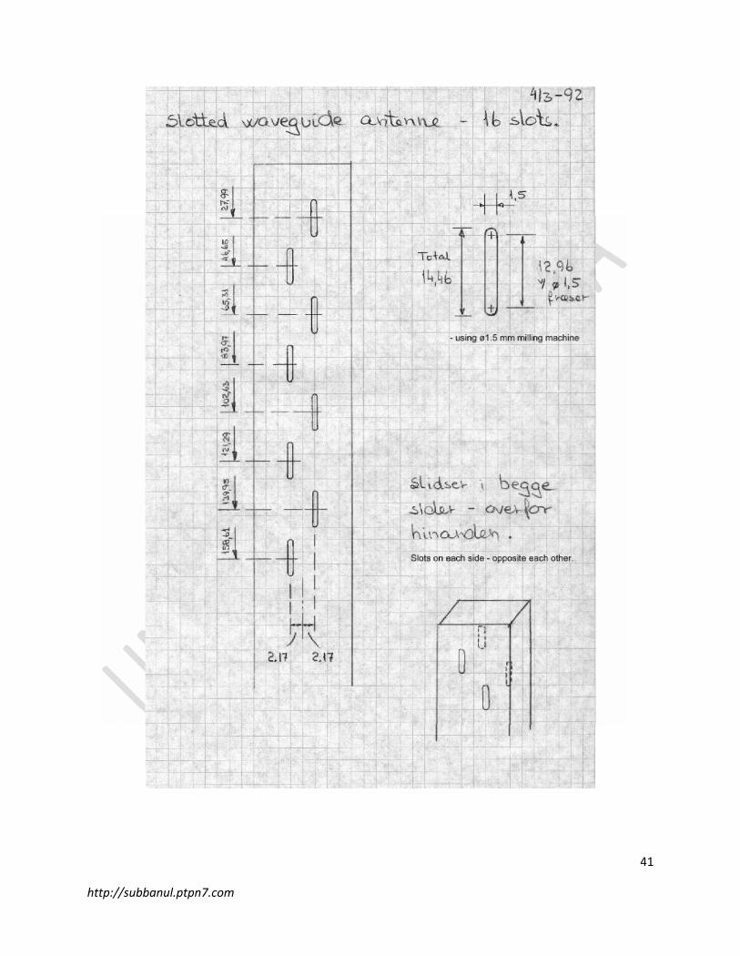
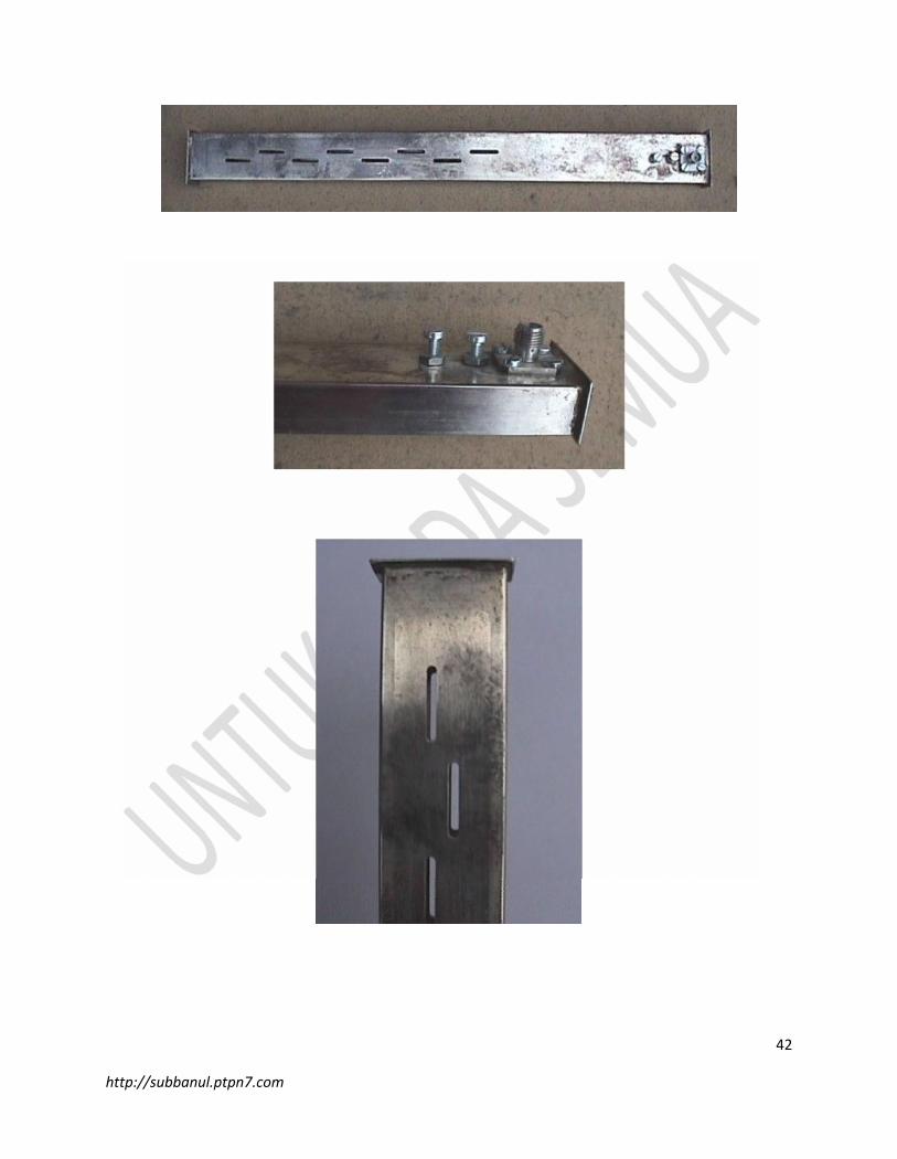
VI. Antena waveguide slot
40
http://subbanul.ptpn7.com
41
http://subbanul.ptpn7.com
42
http://subbanul.ptpn7.com
43
http://subbanul.ptpn7.com
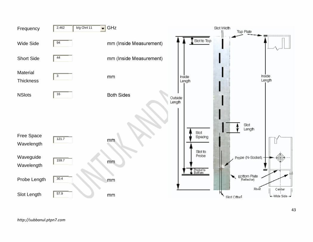
Frequency 2.462 b/g Chnl 11 GHz
Wide Side 94 mm (Inside Measurement)
Short Side 44 mm (Inside Measurement)
Material
Thickness3 mm
NSlots 16 Both Sides
Free Space
Wavelength121.7 mm
Waveguide
Wavelength159.7 mm
Probe Length 30.4 mm
Slot Length 57.9 mm
44
http://subbanul.ptpn7.com
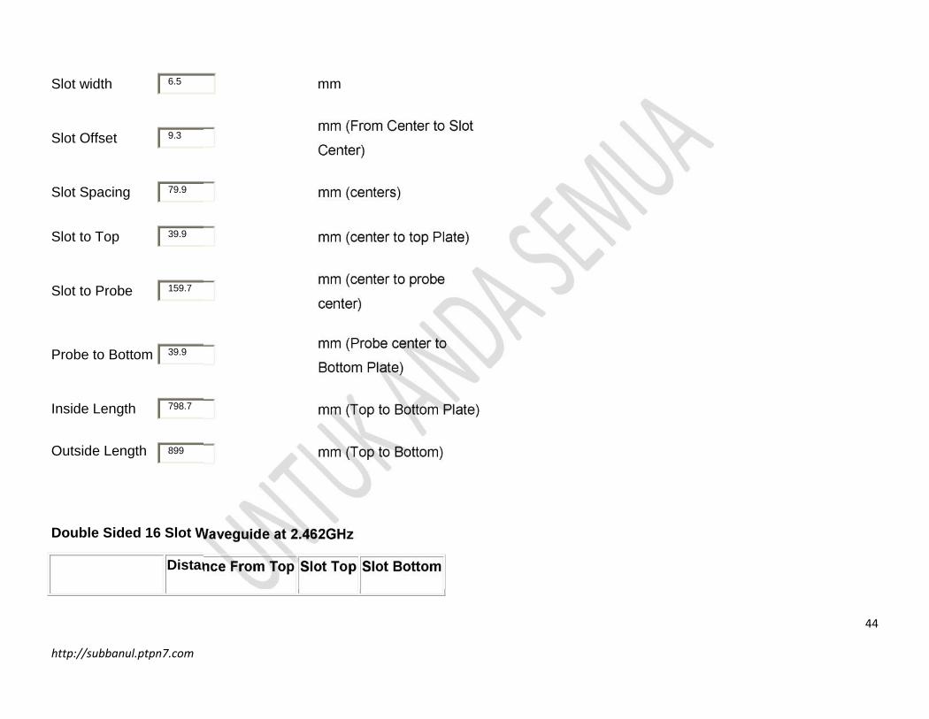
Slot width 6.5 mm
Slot Offset 9.3mm (From Center to Slot
Center)
Slot Spacing 79.9 mm (centers)
Slot to Top 39.9 mm (center to top Plate)
Slot to Probe 159.7mm (center to probe
center)
Probe to Bottom 39.9mm (Probe center to
Bottom Plate)
Inside Length 798.7 mm (Top to Bottom Plate)
Outside Length 899 mm (Top to Bottom)
Double Sided 16 Slot Waveguide at 2.462GHz
Distance From Top Slot Top Slot Bottom
45
http://subbanul.ptpn7.com
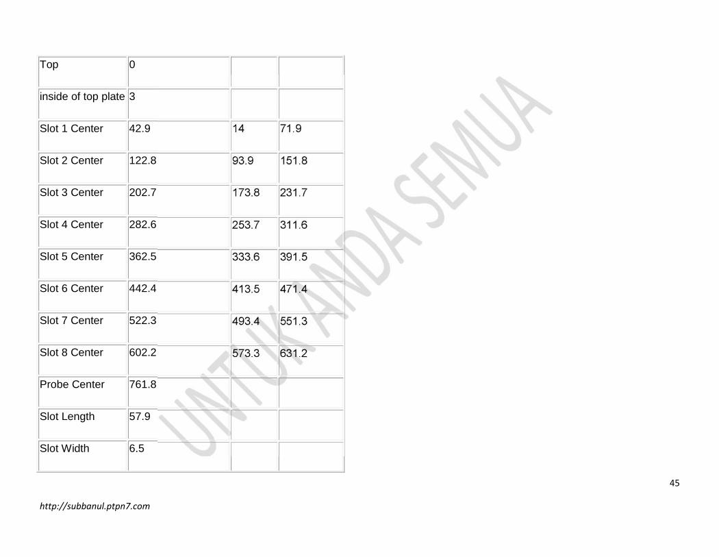
Top 0
inside of top plate 3
Slot 1 Center 42.9 14 71.9
Slot 2 Center 122.8 93.9 151.8
Slot 3 Center 202.7 173.8 231.7
Slot 4 Center 282.6 253.7 311.6
Slot 5 Center 362.5 333.6 391.5
Slot 6 Center 442.4 413.5 471.4
Slot 7 Center 522.3 493.4 551.3
Slot 8 Center 602.2 573.3 631.2
Probe Center 761.8
Slot Length 57.9
Slot Width 6.5
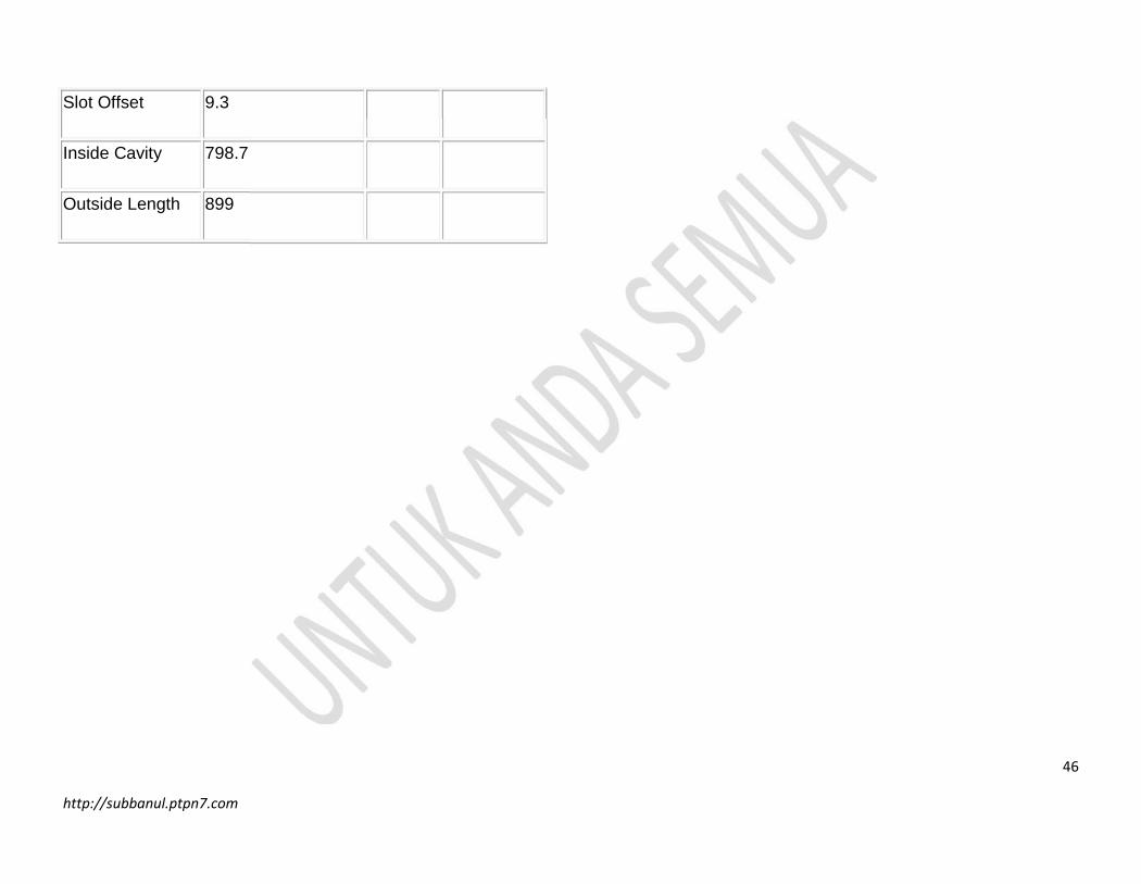
46
http://subbanul.ptpn7.com
Slot Offset 9.3
Inside Cavity 798.7
Outside Length 899
47
http://subbanul.ptpn7.com
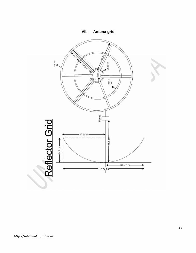
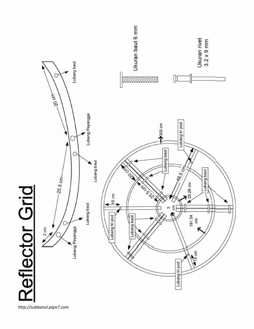
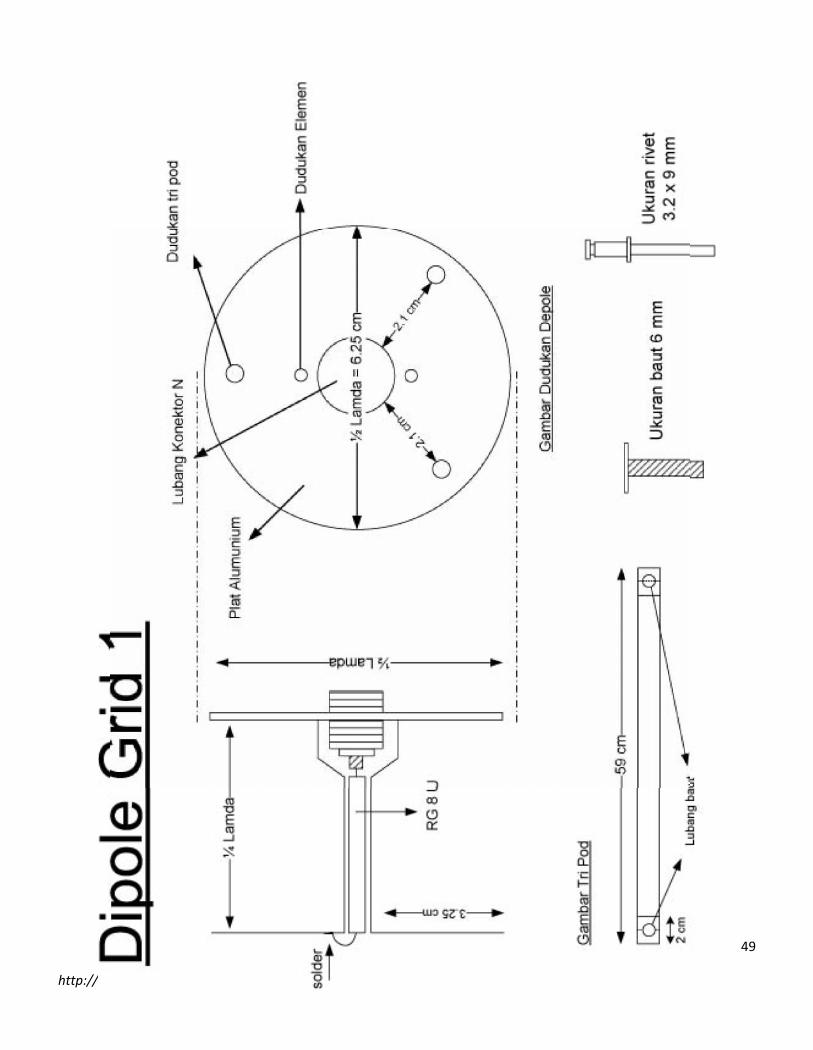
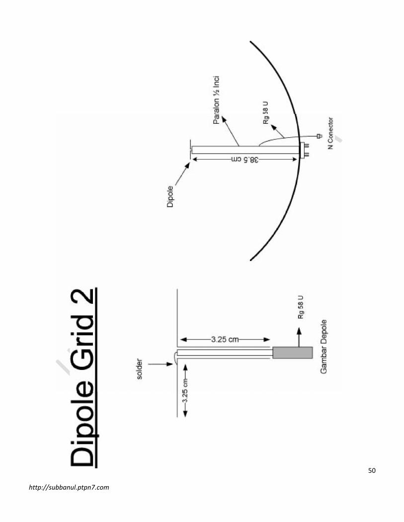
VII. Antena grid
48
http://subbanul.ptpn7.com
49
http://subbanul.ptpn7.com
50
http://subbanul.ptpn7.com
51
http://subbanul.ptpn7.com
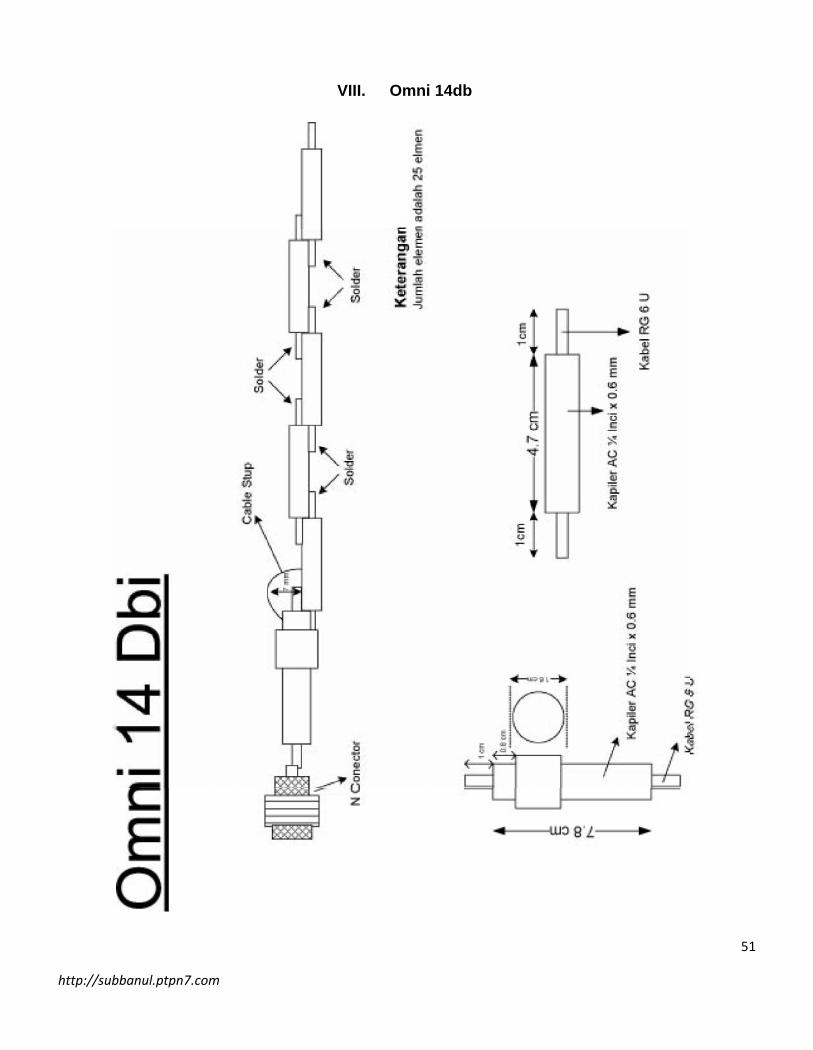
VIII. Omni 14db

52
http://subbanul.ptpn7.com
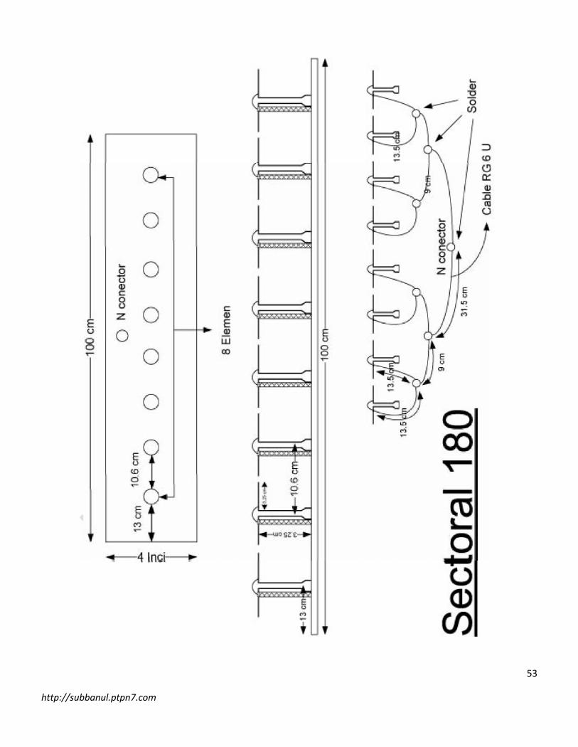
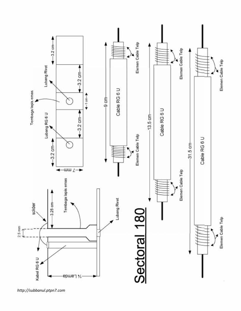
IX. Sectoral 180
53
http://subbanul.ptpn7.com
54
http://subbanul.ptpn7.com


![· Web view– ceturtdaļviļņa vertikālā antena [“ground plane” tipa antena], – antena ar parazītelementiem [jagi],](https://img.pdfslide.tips/doc/110x75/5aae6cbd7f8b9adb688c5507/view-ceturtdalvilna-vertikala-antena-ground-plane-tipa-antena-.jpg)