Embed Size (px)
Citation preview

L854323604/2018 rev. 1
BULL 17 OMIBULL 17 OMAI
UNIONE NAZIONALE COSTRUTTORIAUTOMATISMI PER CANCELLI, PORTE
SERRANDE ED AFFINI
2
A
B
1
204
245
316
398
307
213
398
34mmBULL.PI(Optional)
40
318
204
70180
2
3
B
F
T
4
3
V
R
5
MIN = 10 mmMAX = 20 mm
MIN =120 mmMAX = 140 mm
6
7
R
D
R
D
4
8
≈1 mm
9P
S
MC
10
A
OKF
1 ÷ 3 cm
S
11
B CA
K Max 35 mmX
K X
3 mm 74 mm
35 mm 63 mmBULL 17 OMI.S(optional MLS)
5
12 13
14
C
L
7
4
1
2
3POWER
2 x 1,5
RG
58
54 x 0,25
4
6
5
2 x 0,25
3 x 0,25
15
BAR
6
16
JP1
Safety BAR
J7
SW1
F4
M
8k2
II°Ch. Radio
L
N
GND
GND
NL
SCASERVICE LIGHT
-
+24 Vdc 0.5A
BRAKERESISTOR
PHOTO TEST(fig.15) OPEN/CLOSE
JP1 BAR Open
BAR N.C.
JP1 BARClose
BAR 8K2
U1
LD1
LD2
MOT
MOTCOM
15AT 250Vac
5A
P3
J6
J8
CON1
5A
/BAR OPEN
ANT
RG
58
7
OPEN
OPEN
OPEN
OPEN
18
COM NCNO
RX2TX2
24 V
dc
PH
OTC
CO
M
PH
OTO
TE
ST
COM NCNO
RX1TX124
Vd
c
PH
OTO
TST1:ON TST2:ON
CO
M
PH
OTO
TE
ST
PHOTOTEST OPEN PHOTOTEST CLOSE
+- +- +-+-
19
SCA 24Vac
AUX: 0
Aux: 1
L
NService Light230V
SCA
24V+
-
MAX 16A250Vac
MAX 16A250Vac
LOGIC MINV
SCA SERVICE LIGHT
OPEN
Open Safety Edge
COM PHOTO
Close Safety Edge
(8K2/N.O. Jumper)BAR BAR
MOTOR
J3 Open
BAR N.C.
J3Close
BAR 8K2
N.C.
21
bar:On
BAR LOGIC=ON
SCA 24Vac
AUX: 0
Aux: 1
L
NService Light230V
SCA
24V+
-
MAX 16A250Vac
MAX 16A250Vac
20
17
MINV:Off
MINV:On
8
log
nMan
v1.00
8888 PRG
PRG
PRG
PRG
PRG
PRG
PRG
PRG
PRG
PRG
PRG
PRG
PRG
PRG
tca
tped
tsmo
tsmc
fsto
sldo
sldc
pmo
pMc
seav
sear
40
20
20
20
45
fstc
25
25
85
85
60
60
blo 3
blc 3
45
PAR
Power ON
Display OFF
Firmware Ver. (3s)
Diagnostic on PRG
OFF PRG
OFF PRG
OFF PRG
OFF PRG
LOG tca
IBL
IBCA
SCL
PP
OFF PRGPRE
OFF PRG
off PRG
off PRG
OFF PRG
htr
ltca
pho1
pho2
PRGtls 60
PRGtacc 20
res PRG
OFF PRG
0012 3456Nman
MACI
RES
0000 conf OKCODE
par
9000 9C5a
AUTO OKPUSH
RE-ENTERCODE
Display OFF
2 CycleOPEN/CLOSE
PRG
PRG
PRG
PRG
mot 0 0
1
2
3
1
2
3
YAK 25BISON 35
BULL 15OMI230Vac
BULL 15OMAI115Vac
_ _ _ _ _ _
0
PRG
PRG
PRG
PRG
tdec
tbr
50
4
spin 2
aux 0
tca
off PRG
off PRG
off PRG
off PRG
TCA
tst1
tst2
bar
minv
off PRGHorm
9
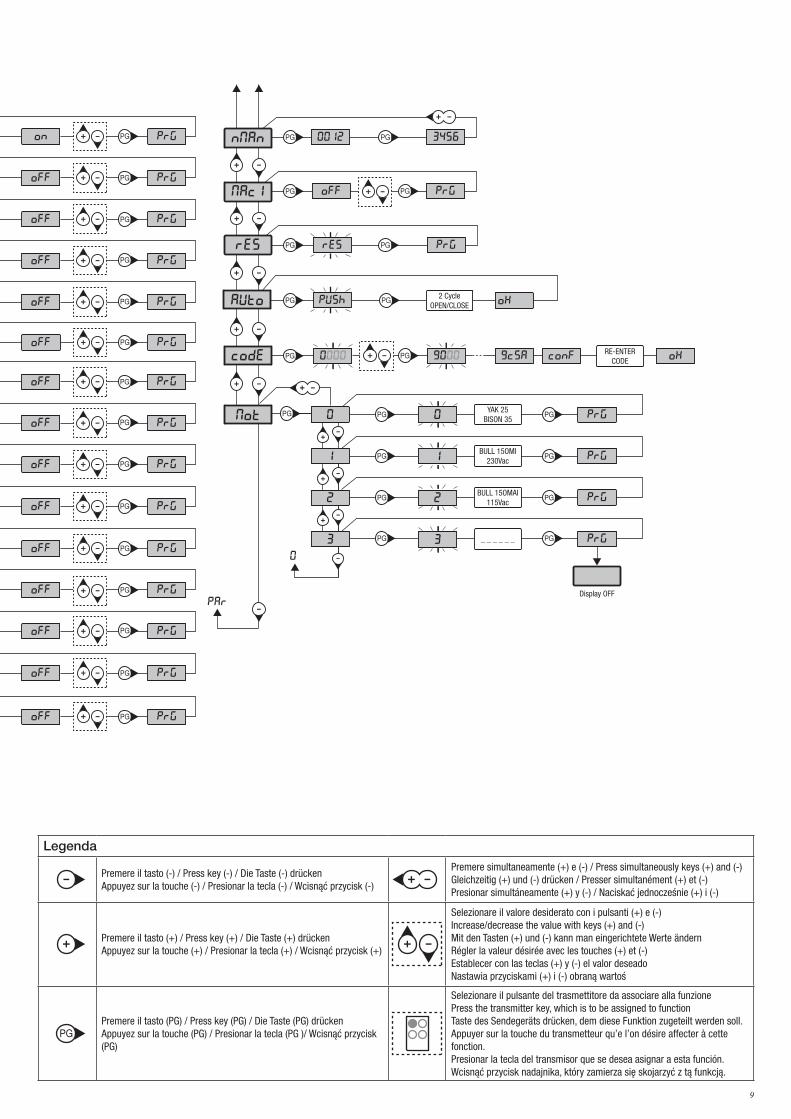
Legenda
Premere il tasto (-) / Press key (-) / Die Taste (-) drückenAppuyez sur la touche (-) / Presionar la tecla (-) / Wcisnąć przycisk (-)
Premere simultaneamente (+) e (-) / Press simultaneously keys (+) and (-)Gleichzeitig (+) und (-) drücken / Presser simultanément (+) et (-)Presionar simultáneamente (+) y (-) / Naciskać jednocześnie (+) i (-)
Premere il tasto (+) / Press key (+) / Die Taste (+) drückenAppuyez sur la touche (+) / Presionar la tecla (+) / Wcisnąć przycisk (+)
Selezionare il valore desiderato con i pulsanti (+) e (-)Increase/decrease the value with keys (+) and (-)Mit den Tasten (+) und (-) kann man eingerichtete Werte ändernRégler la valeur désirée avec les touches (+) et (-)Establecer con las teclas (+) y (-) el valor deseadoNastawia przyciskami (+) i (-) obraną wartoś
Premere il tasto (PG) / Press key (PG) / Die Taste (PG) drückenAppuyez sur la touche (PG) / Presionar la tecla (PG )/ Wcisnąć przycisk (PG)
Selezionare il pulsante del trasmettitore da associare alla funzione Press the transmitter key, which is to be assigned to functionTaste des Sendegeräts drücken, dem diese Funktion zugeteilt werden soll.Appuyer sur la touche du transmetteur qu’e l’on désire affecter à cette fonction.Presionar la tecla del transmisor que se desea asignar a esta función.Wcisnąć przycisk nadajnika, który zamierza się skojarzyć z tą funkcją.
log
nMan
v1.00
8888 PRG
PRG
PRG
PRG
PRG
PRG
PRG
PRG
PRG
PRG
PRG
PRG
PRG
PRG
tca
tped
tsmo
tsmc
fsto
sldo
sldc
pmo
pMc
seav
sear
40
20
20
20
45
fstc
25
25
85
85
60
60
blo 3
blc 3
45
PAR
Power ON
Display OFF
Firmware Ver. (3s)
Diagnostic on PRG
OFF PRG
OFF PRG
OFF PRG
OFF PRG
LOG tca
IBL
IBCA
SCL
PP
OFF PRGPRE
OFF PRG
off PRG
off PRG
OFF PRG
htr
ltca
pho1
pho2
PRGtls 60
PRGtacc 20
res PRG
OFF PRG
0012 3456Nman
MACI
RES
0000 conf OKCODE
par
9000 9C5a
AUTO OKPUSH
RE-ENTERCODE
Display OFF
2 CycleOPEN/CLOSE
PRG
PRG
PRG
PRG
mot 0 0
1
2
3
1
2
3
YAK 25BISON 35
BULL 15OMI230Vac
BULL 15OMAI115Vac
_ _ _ _ _ _
0
PRG
PRG
PRG
PRG
tdec
tbr
50
4
spin 2
aux 0
tca
off PRG
off PRG
off PRG
off PRG
TCA
tst1
tst2
bar
minv
off PRGHorm
10
ITA AVVERTENZEINFORMAZIONI GENERALIE’ vietato l’utilizzo del prodotto per scopi o con modalità non previste nel presente manuale. Usi non corretti possono essere causa di danni al prodotto e mettere in pericolo persone e cose. Si declina ogni responsabilità dall’inosservanza della buona tecnica nella costruzione dei cancelli, nonché dalle deformazioni che potrebbero verificarsi durante l’uso. Conservare questo manuale per futuri utilizzi.
INFORMAZIONI PER L'INSTALLATOREQuesto manuale è destinato esclusivamente a personale qualificato per l’installazione e la manutenzione di aperture automatiche.L’installazione deve essere effettuaua da personale qualificato (installatore professionale, secondo EN12635), nell’osservanza della Buona Tecnica e delle norme vigenti. Verificare che la struttura del cancello sia adatta ad essere automatizzata.L’installatore deve fornire tutte le informazioni relative al funzionamento automatico, manuale e di emergenza dell’automazione, e conseg-nare all’utilizzatore dell’impianto le istruzioni d’uso.
AVVERTENZE GENERALII materiali dell’imballaggio non devono essere lasciati alla portata dei bambini in quanto fonte di potenziale pericolo. Non disperdere nell’ambiente i materiali di imballo, ma separare le varie tipologie (es. cartone, polistirolo) e smaltirle secondo le normative locali.Non permettere ai bambini di giocare con i dispositivi di comando del prodotto. Tenere i telecomandi lontano dai bambini.Questo prodotto non è destinato a essere utilizzato da persone (bambini inclusi) con capacità fisiche, sensoriali o mentali ridotte, o con mancanza di conoscenze adeguate, a meno che non siano sotto supervisione o abbiano ricevuto istruzioni d’uso da persone responsabili della loro sicurezza. Applicare tutti i dispositivi di sicurezza (fotocellule, coste sensibili, ecc.) necessari a proteggere l’area da pericoli di impatto, schiacciamento, convogliamento, cesoiamento. Tenere in considerazione le normative e le direttive in vigore, i criteri della Buona Tecnica, l’utilizzo, l’ambiente di installazione, la logica di funzionamento del sistema e le forze sviluppate dall’automazione.L’installazione deve essere fatta utilizzando dispositivi di sicurezza e di comandi conformi alla EN12978 e EN12453.Raccomandiamo di utilizzare accessori e parti di ricambio originali, utilizzando ricambi non originali il prodotto non sarà più coperto da garanzia.Tutte le parti meccaniche ed elettroniche che compongono l'automazione soddisfano i requisiti e le norme in vigore e presentano marca-tura CE.
SICUREZZA ELETTRICAPrevedere sulla rete di alimentazione un interruttore/sezionatore onnipolare con distanza d’apertura dei contatti uguale o superiore a 3 mm.Verificare che a monte dell’impianto elettrico vi sia un interruttore differenziale e una protezione di sovracorrente adeguati.Alcune tipologie di installazione richiedono il collegamento dell’anta ad un impianto di messa a terra rispondente alle vigenti norme di sicurezza.Durante gli interventi di installazione, manutenzione e riparazione, togliere l’alimentazione prima di accedere alle parti elettriche.Scollegare anche eventuali batterie tampone se presenti. L’installazione elettrica e la logica di funzionamento devono essere in accordo con le normative vigenti. I conduttori alimentati con tensioni diverse, devono essere fisicamente separati, oppure devono essere adeguatamente isolati con isolamento supplementare di almeno 1 mm. I conduttori devono essere vincolati da un fissaggio supplementare in prossimità dei morsetti. Ricontrollare tutti i collegamenti fatti prima di dare tensione. Gli ingressi N.C. non utilizzati devono essere ponticellati.
SMALTIMENTOCome indicato dal simbolo a lato, è vietato gettare questo prodotto nei rifiuti domestici in quanto alcune parti che lo compongono potreb-bero risultare nocive per l’ambiente e la salute umana, se smaltite scorrettamente. L’apparecchiatura, pertanto, dovrà essere consegnata in adeguati centri di raccolta differenziata, oppure riconsegnata al rivenditore al momento dell’acquisto di una nuova apparecchiatura equivalente. Lo smaltimento abusivo del prodotto da parte dell’utente comporta l’applicazione delle sanzioni amministrative previste dalla normativa vigente.
Le descrizioni e le illustrazioni presenti in questo manuale non sono impegnative. Lasciando inalterate le caratteristiche essenziali del prodotto il fab-bricante si riserva il diritto di apportare qualsiasi modifica di carattere tecnico, costruttivo o commerciale senza impegnarsi ad aggiornare la presente pubblicazione.
ATTENZIONE!La centrale utilizza condensatori ad alta capacità che posso risultare pericolosi anche in assenza di alimen-tazione di rete. E' indispensabile attendere almeno 60 secondi dopo aver disconnesso l'alimentazione di rete prima di accedere alla centrale.
Read Instructions
DO NOT TOUCH!DISCONNECT M A I N S U P P LY WAIT!
60 sec.
WARNING!
F8369256
Etichetta WARNING: Formato 55x50mm
stampa su PVC adesivo4 colori
Read Instructions
DO NOT TOUCH!DISCONNECT M A I N S U P P LY WAIT!
60 sec.
WARNING!
F8369256
Etichetta WARNING: Formato 55x50mm
stampa su PVC adesivo4 colori
11
1) CARATTERISTICHE GENERALIAutomazione con alimentazione monofase per cancelli scorrevoli.
2) NOTIZIE GENERALIPer un buon funzionamento dell’automazione per scorrevoli, la porta da automatizzare, dovrà rispondere alle seguenti caratteristiche:- la rotaia di guida e relative ruote devono essere opportunamente dimensionate e manutenzionate (onde evitare eccessivi attriti durante lo scorrimento
del cancello.- durante il funzionamento la porta non deve presentare eccessivi ondeggiamenti.- la corsa di apertura e chiusura deve essere limitata da un arresto meccanico (secondo normativa di sicurezza vigente).
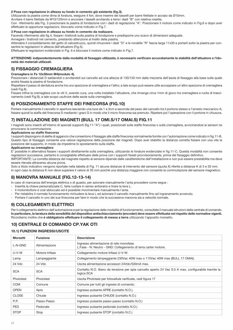
3) DATI TECNICI
BULL 17 OMI BULL 17 OMAI
Alimentazione 230Vac 50/60Hz 115Vac 60Hz
Assorbimento 7 A 8 A
Coppia 68 Nm 40 Nm
Inverter SI SI
Intermittenza di lavoro 40% 40%
Grado di protezione IP44 IP44
Temp. funzionamento -20°C / +50°C -20°C / +50°C
Peso max. cancello 1700 kg 1700 kg
Modulo cremagliera M4 Z 18* M4 Z 18*
Velocità apertura 24 m/min MAX 24 m/min MAX
Rumorosità <70 dB <70 dB
Lubrificazione Olio Olio
Peso 21,3 kg 21,3 kg
* M6 Z13 (art. RI.P6 - opzionale)
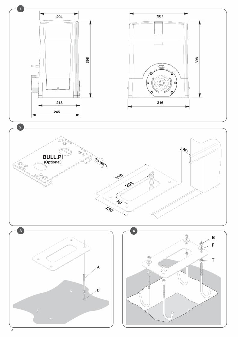
4) MESSA IN POSA DELLA PIASTRA DI FONDAZIONEIn fig. 2 sono rappresentate le dimensioni della piastra di fondazione.E' indispensabile rispettare la distanza dalla cremagliera per poter posizionare e rimuovere l'attuatore una volta fissata la cremagliera all'anta.Le tipologie di fissaggio della piastra di fondazione sono principalmente le seguenti:
1 Posa senza regolazione in altezza su fondo in cemento già esistente (fig.2). Utilizzando la piastra come dima di foratura, eseguire 4 fori Ø10mm, nei quali inserire dei tasselli filettati in acciaio Ø10x120mm simili a quelli rappresentati in Fig. 2. Bloccare direttamente a terra l'attuatore come indicato in Fig.7.
PROGRAMMAZIONE RAPIDA- Impostare la posizione del motore nel menu minv, di default è impostata come motore a sinistra.
- Entrare nel menu AUTO, confermare con PG per 2 volte ed eseguire l'acquisizione dei parametri ottimali di funzionamento
- Selezionare nei menu PAR e LOG i parametri e le logiche di funzionamento richieste in base alla tipologia di installazione.
IMPORTANTE: Dopo ogni variazione dei parametri FSTO, FSTC. SLDO, SLDC, TSMO, TSMC, l'automazione esegue una ma-novra di apertura e chiusura completa per acquisire i nuovi valori di corrente e coppia, sul display compare il messaggio "PRG".
- Per memorizzare il trasmettitore premere il pulsante sul ricevitore ad innesto.
1) CARATTERISTICHE GENERALI ....................................................................11
2) NOTIZIE GENERALI ....................................................................................11
3) DATI TECNICI.............................................................................................11
4) MESSA IN POSA DELLA PIASTRA DI FONDAZIONE .....................................11
5) FISSAGGIO CREMAGLIERA .........................................................................12
6) POSIZIONAMENTO STAFFE DEI FINECORSA (FIG.10) ..................................12
7) INSTALLAZIONE DEI MAGNETI (BULL 17 OMI.S/17 OMAI.S) FIG.11 ............12
8) MANOVRA MANUALE (FIG.12-13-14) ........................................................12
9) COLLEGAMENTI ELETTRICI ........................................................................12
10) CENTRALE DI COMANDO CP.YAK OTI .......................................................12
10.1) FUNZIONI INGRESSI/USCITE ........................................................... 12
10.2) VERIFICA COLLEGAMENTI .............................................................. 13
11) PROGRAMMAZIONE ................................................................................13
12) PER ACCEDERE ALLA PROGRAMMAZIONE ...............................................13
12.1) AUTOAPPREND. QUOTE E TARATURA DISP. ANTISCHIACCIAMENTO . 13
13) PARAMETRI, LOGICHE E FUNZIONI SPECIALI ............................................14
14) REGOLAZIONE VELOCITÀ E RALLENTAMENTI ...........................................16
15) AUTOSET ................................................................................................17
16) MESSAGGI DI ERRORE ............................................................................18
17) DISPLAY LCD ..........................................................................................18
18) DIAGNOSTICA .........................................................................................18
19) MANUTENZIONE......................................................................................19
SOMMARIO
12
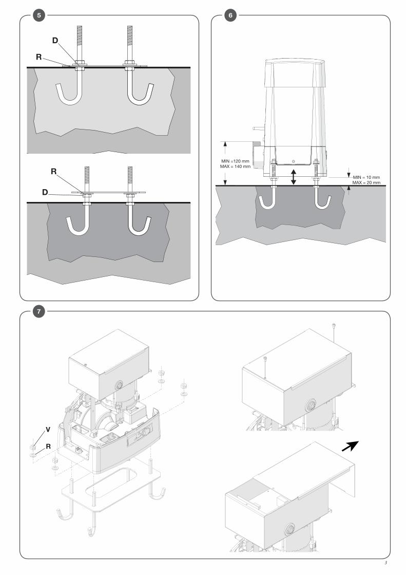
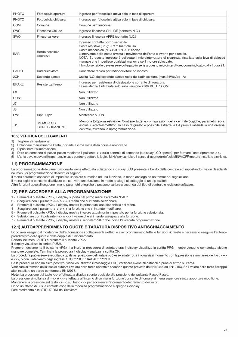
2 Posa con regolazione in altezza su fondo in cemento già esistente (fig.3). Utilizzando la piastra come dima di foratura, eseguire 4 fori, dove inserire dei tasselli per barre filettate in acciaio da Ø10mm.Avvitare 4 barre filettate da M10/120mm e ancorare i tasselli avvitando a terra i dadi "B" con relativa rosetta.Con riferimento alla Fig. 3 posizionare la piastra di fondazione con i dadi di regolazione "A". Posizionare il motore come indicato in Fig.6 e dopo aver effettuato le opportune regolazioni, bloccarlo come indicato in Fig.7.
3 Posa con regolazione in altezza su fondo in cemento da realizzare. Facendo riferimento alla fig.4, fissare i tirafondi sulla piastra di fondazione e predisporre uno scavo di dimensioni adeguate.Annegare i tirafondi nel cemento, prestando attenzione al livello della piastra. Attendere il consolidamento del getto di calcestruzzo, quindi rimuovere i dadi "D" e le rondelle "R" fascia larga 11x30 e portarli sotto la piastra per con-sentire le regolazioni in altezza dell'attuatore (Fig.5).Effettuare le regolazioni evidenziate in Fig. 6 e bloccare il motore come indicato in Fig.7.
ATTENZIONE: indipendentemente dalla modalità di fissaggio utilizzata, è necessario verificare accuratamente la stabilità dell'attuatore e l'ido-neità dei materiali utilizzati.
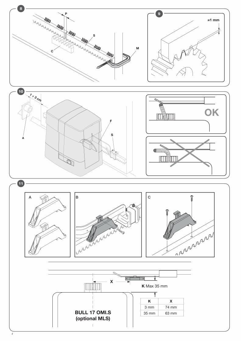
5) FISSAGGIO CREMAGLIERACremagliera in Fe 12x30mm M4(modulo 4).Posizionare i distanziali D saldandoli o avvitandoli sul cancello ad una altezza di 130/150 mm dalla mezzeria dell’asola di fissaggio alla base sulla quale andrà fissata la piastra di fondazione. Rispettare il passo di dentatura anche tra uno spezzone di cremagliera e l’altro; a tale scopo può essere utile accoppiare un’altro spezzone di cremagliera (vedi Fig.8).Fissare infine la cremagliera con le viti V, avendo cura, una volta installato l’attuatore, che rimanga circa 1mm di gioco tra cremagliera e ruota di trasci-namento (vedi Fig.9); a tale scopo usufruire delle asole sulla cremagliera.
6) POSIZIONAMENTO STAFFE DEI FINECORSA (FIG.10)Portare manualmente il cancello in apertura lasciando una luce da 1 a 3cm a seconda del peso del cancello tra il portone stesso e l’arresto meccanico A; fissare quindi la staffa del finecorsa S mediante i grani G in modo che il micro finecorsa sia premuto. Ripetere poi l’operazione con il portone in chiusura.
7) INSTALLAZIONE DEI MAGNETI (BULL 17 OMI.S/17 OMAI.S) FIG.11I magneti sono inseriti all’interno di speciali supporti (fig.11-”A”) i quali, posizionati sulle staffe finecorsa o sulla cremagliera, avvicinandosi ai sensori ne provocano la commutazione.Applicazione su staffe finecorsaI supporti dispongono di alette di aggancio che consentono il fissaggio alle staffe finecorsa normalmente fornite con l’automazione come indicato in fig.11-B.Questo tipo di fissaggio consente una veloce regolazione della posizione dei magneti. Dopo aver stabilito la distanza corretta fissare con una vite la posizione del supporto, in modo da impedirne lo spostamento sulla staffa.Applicazione su cremaglieraE’ possibile in alternativa fissare i supporti direttamente sulla cremagliera, utilizzando le forature evidenziate in fig.11-C. Questa modalità non consente regolazioni successive, pertanto è consigliabile effettuare delle prove con i supporti fissati provvisoriamente, prima del fissaggio definitivo.IMPORTANTE: La corretta distanza del magnete rispetto al sensore dipende dalle caratteristiche dell’installazione e non può essere prestabilita ma deve essere rilevata attraverso alcune prove.Solo a titolo indicativo vengono riportate nella tabella di Fig. 11 alcune distanze di intervento del sensore (quota X) riferite a distanze K di 3 e 35 mm.In ogni caso la distanza K non deve superare il valore di 35 mm poiché una distanza maggiore non consente la commutazione del sensore magnetico.
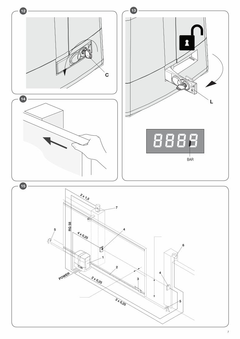
8) MANOVRA MANUALE (FIG.12-13-14)In caso di mancanza dell’energia elettrica o di guasto, per azionare manualmente l'anta procedere come segue : - Inserita la chiave personalizzata C, farla ruotare in senso antiorario e tirare la leva L.- Il motoriduttore è così sbloccato ed è possibile movimentare manualmente l'anta.- Per ristabilire il normale funzionamento richiudere la leva L ed azionare il cancello manualmente fino ad ingranamento avvenuto.- Portare il cancello in uno dei sue finecorsa per fare in modo che la successiva manovra sia a velocità normale.
9) COLLEGAMENTI ELETTRICIPer il collegamento elettrico dell'automazione e per la regolazione delle modalità di funzionamento, consultate il manuale istruzioni della centrale di comando.In particolare, la taratura della sensibilità del dispositivo antischiacciamento (encoder) deve essere effettuata nel rispetto delle normative vigenti.Ricordiamo inoltre che è obbligatorio effettuare il collegamento di messa a terra utilizzando l'apposito morsetto.
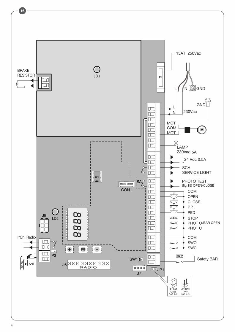
10) CENTRALE DI COMANDO CP.YAK OTI
10.1) FUNZIONI INGRESSI/USCITE
Morsetti Funzione Descrizione
L-N-GND AlimentazioneIngresso alimentazione di rete monofase.L:Fase - N: Neutro - GND: Collegamento di terra carter motore.
U-V-W Motore trifase Collegamento motore trifase U-V-W.
Lamp Lampeggiante Collegamento lampeggiante 230Vac 40W max o 115Vac 40W max (BULL 17 OMAI).
24 Vdc 24 Vdc Uscita alimentazione accessori 24Vdc/500mA max.
SCA SCAContatto N.O. libero da tensione per spia cancello aperto 24 Vac 0.5 A max, configurabile tramite la logica SCA
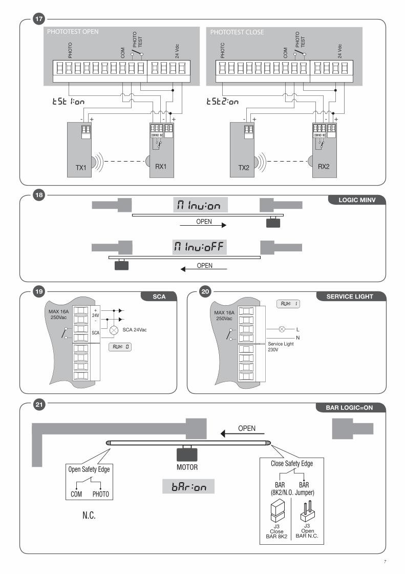
Phototest Phototest Uscita Phototest per fotocellule verificate, vedi figura 17
COM Comune Comune per tutti gli ingressi di comando.
OPEN Apre Ingresso pulsante APRE (contatto N.O.).
CLOSE Chiude Ingresso pulsante CHIUDE (contatto N.O.)
P.P. Passo-Passo Ingresso pulsante passo-passo (contatto N.O.)
PED Pedonale Ingresso pulsante pedonale (contatto N.O.)
STOP Stop Ingresso pulsante STOP (contatto N.C.)
13
PHOTO Fotocellula apertura Ingresso per fotocellula attiva solo in fase di apertura
PHOTC Fotocellula chiusura Ingresso per fotocellula attiva solo in fase di chiusura
COM Comune Comune per finecorsa.
SWC Finecorsa Chiude Ingresso finecorsa CHIUDE (contatto N.C.)
SWO Finecorsa Apre Ingresso finecorsa APRE (contatto N.C.)
BARBordo sensibile sicurezza
Ingresso contatto bordo sensibileCosta resistiva (8K2): JP1 “BAR” chiusoCosta meccanica (N.C.): JP1 “BAR” apertoL’intervento della costa arresta il movimento dell’anta e inverte per circa 3s.NOTA: Su questo ingresso è collegato il microinterruttore di sicurezza installato sulla leva di sblocco manuale che impedisce qualsiasi manovra se il motore sbloccato.Il bordo sensibile deve essere collegato in serie a questo microinteruttore, come indicato dalla figura 21.
RADIO Radioricevitore Connettore rapido per radioricevitore ad innesto.
2CH Secondo canale Uscita N.O. del secondo canale radio del radiricevitore. (max 24Vac/dc 1A)
BRAKE Resistenza FrenoIngresso per resistenza di dissipazione corrente di frenatura. La resistenza è utilizzata solo sulla versione 230V BULL 17 OMI
P3 Non utilizzato
CON1 Non utilizzato
J7 Non utilizzato
J8 Non utilizzato
SW1 Dip1, Dip2 Mantenere su ON
U1MEMORIA DI CONFIGURAZIONE
Memoria E-Eprom estraibile. Contiene tutte le configurazioni della centrale (logiche, parametri, ecc), esclusi i radiotrasmettitori. In caso di guasto è possibile estrarre la E-Eprom e inserirla in una diversa centrale, evitando la riprogrammazione.
10.2) VERIFICA COLLEGAMENTI1) Togliere alimentazione.2) Sbloccare manualmente l’anta, portarla a circa metà della corsa e ribloccarle.3) Ripristinare l’alimentazione.4) Dare un comando di passo-passo mediante il pulsante <-> sulla centrale di comando (a display LCD spento), per fermare l’anta ripremere <->.5) L’anta deve muoversi in apertura, in caso contrario settare la logica MINV per cambiare il senso di apertura (default MINV=OFF) motore installato a sinistra.
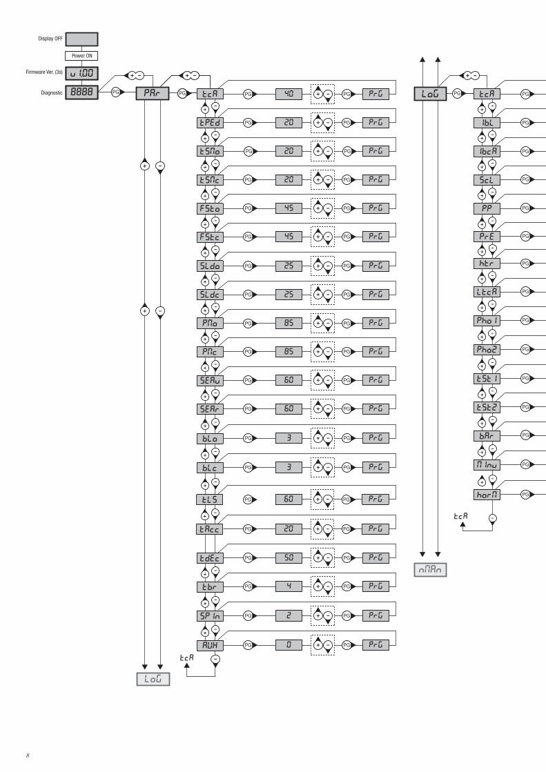
11) PROGRAMMAZIONELa programmazione delle varie funzionalità viene effettuata utilizzando il display LCD presente a bordo della centrale ed impostando i valori desiderati nei menu di programmazione descritti di seguito. Il menu parametri consente di impostare un valore numerico ad una funzione, in modo analogo ad un trimmer di regolazione.Il menu logiche consente di attivare o disattivare una funzione, in modo analogo al settaggio di un dip-switch.Altre funzioni speciali seguono i menu parametri e logiche e possono variare a seconda del tipo di centrale o revisione software.
12) PER ACCEDERE ALLA PROGRAMMAZIONE1 - Premere il pulsante <PG>, il display si porta nel primo menu Parametri “PAR”. 2 - Scegliere con il pulsante <+> o <-> il menu che si intende selezionare.3- Premere il pulsante <PG>, il display mostra la prima funzione disponibile nel menu.4 - Scegliere con il pulsante <+> o <-> la funzione che si intende modificare.5 - Premere il pulsante <PG>, il display mostra il valore attualmente impostato per la funzione selezionata.6 - Selezionare con il pulsante <+> o <-> il valore che si intende assegnare alla funzione.7 - Premere il pulsante <PG>, il display mostra il segnale “PRG” che indica l’avvenuta programmazione.
12.1) AUTOAPPRENDIMENTO QUOTE E TARATURA DISPOSITIVO ANTISCHIACCIAMENTODopo aver eseguito il montaggio dell’automazione i collegamenti elettrici e aver programmato tutte le funzioni richieste è necessario eseguire l’autoap-prendimento delle quote e delle coppie di funzionamento.Portarsi nel menu AUTO e premere il pulsante <PG>Il display visualizza la scritta PUSH.Premere nuovamente il pulsante <PG>, ha inizio la procedura di autotaratura: il display visualizza la scritta PRG, mentre vengono comandate alcune manovre complete. Terminata la procedura il display visualizza la scritta OK.La procedura può essere eseguita da qualsiasi posizione dell’anta e può essere interrotta in qualsiasi momento con la pressione simultanea dei tasti <+> e <->, o con l’intervento degli ingressi STOP/PHO/PHA/BAR/PP/PED.Se la procedura non ha esito positivo, viene visualizzato il messaggio ERR, verificare eventuali ostacoli o punti di attrito sull’anta.Verificare al termine della fase di autoset il valore delle forze operative secondo quanto previsto da EN12445 ed EN12453. Se il valore della forza è troppo alto installare un bordo conforme a EN12978.Note: La pressione del tasto <-> effettuata a display spento equivale alla pressione del pulsante Passo-Passo. La pressione simultanea di <+> e <-> effettuata all’interno di un menu funzione consente di tornare al menu superiore senza apportare modifiche.Mantenere la pressione sul tasto <+> o sul tasto <-> per accelerare l’incremento/decremento dei valori.Dopo un’attesa di 30s la centrale esce dalla modalità programmazione e spegne il display.Fare riferimento alle ISTRUZIONI del ricevitore.
14
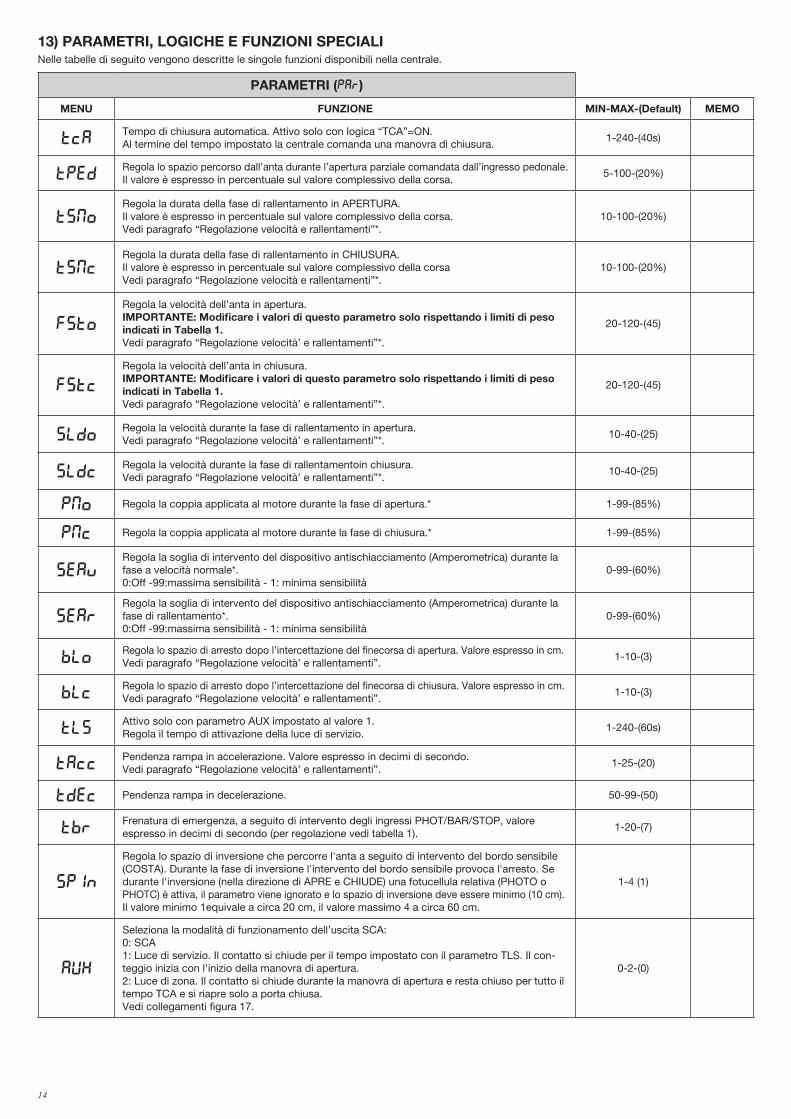
13) PARAMETRI, LOGICHE E FUNZIONI SPECIALINelle tabelle di seguito vengono descritte le singole funzioni disponibili nella centrale.
PARAMETRI (PAR)
MENU FUNZIONE MIN-MAX-(Default) MEMO
TCATempo di chiusura automatica. Attivo solo con logica “TCA”=ON.Al termine del tempo impostato la centrale comanda una manovra di chiusura.
1-240-(40s)
TpedRegola lo spazio percorso dall’anta durante l’apertura parziale comandata dall’ingresso pedonale. Il valore è espresso in percentuale sul valore complessivo della corsa.
5-100-(20%)
tsmoRegola la durata della fase di rallentamento in APERTURA. Il valore è espresso in percentuale sul valore complessivo della corsa.Vedi paragrafo “Regolazione velocità e rallentamenti”*.
10-100-(20%)
tsMcRegola la durata della fase di rallentamento in CHIUSURA.Il valore è espresso in percentuale sul valore complessivo della corsaVedi paragrafo “Regolazione velocità e rallentamenti”*.
10-100-(20%)
FSTo
Regola la velocità dell’anta in apertura.IMPORTANTE: Modificare i valori di questo parametro solo rispettando i limiti di peso indicati in Tabella 1.Vedi paragrafo “Regolazione velocità’ e rallentamenti”*.
20-120-(45)
FSTc
Regola la velocità dell’anta in chiusura.IMPORTANTE: Modificare i valori di questo parametro solo rispettando i limiti di peso indicati in Tabella 1.Vedi paragrafo “Regolazione velocità’ e rallentamenti”*.
20-120-(45)
sldoRegola la velocità durante la fase di rallentamento in apertura.Vedi paragrafo “Regolazione velocità’ e rallentamenti”*.
10-40-(25)
sldcRegola la velocità durante la fase di rallentamentoin chiusura.Vedi paragrafo “Regolazione velocità’ e rallentamenti”*.
10-40-(25)
PMO Regola la coppia applicata al motore durante la fase di apertura.* 1-99-(85%)
PMC Regola la coppia applicata al motore durante la fase di chiusura.* 1-99-(85%)
sEavRegola la soglia di intervento del dispositivo antischiacciamento (Amperometrica) durante la fase a velocità normale*. 0:Off -99:massima sensibilità - 1: minima sensibilità
0-99-(60%)
sEarRegola la soglia di intervento del dispositivo antischiacciamento (Amperometrica) durante la fase di rallentamento*.0:Off -99:massima sensibilità - 1: minima sensibilità
0-99-(60%)
bloRegola lo spazio di arresto dopo l’intercettazione del finecorsa di apertura. Valore espresso in cm. Vedi paragrafo “Regolazione velocità’ e rallentamenti”.
1-10-(3)
blcRegola lo spazio di arresto dopo l’intercettazione del finecorsa di chiusura. Valore espresso in cm. Vedi paragrafo “Regolazione velocità’ e rallentamenti”.
1-10-(3)
TLSAttivo solo con parametro AUX impostato al valore 1. Regola il tempo di attivazione della luce di servizio.
1-240-(60s)
TACCPendenza rampa in accelerazione. Valore espresso in decimi di secondo.Vedi paragrafo “Regolazione velocità’ e rallentamenti”.
1-25-(20)
TDEC Pendenza rampa in decelerazione. 50-99-(50)
TbrFrenatura di emergenza, a seguito di intervento degli ingressi PHOT/BAR/STOP, valore espresso in decimi di secondo (per regolazione vedi tabella 1).
1-20-(7)
SPIn
Regola lo spazio di inversione che percorre l'anta a seguito di intervento del bordo sensibile (COSTA). Durante la fase di inversione l'intervento del bordo sensibile provoca l'arresto. Se durante l'inversione (nella direzione di APRE e CHIUDE) una fotucellula relativa (PHOTO o PHOTC) è attiva, il parametro viene ignorato e lo spazio di inversione deve essere minimo (10 cm).Il valore minimo 1equivale a circa 20 cm, il valore massimo 4 a circa 60 cm.
1-4 (1)
Aux
Seleziona la modalità di funzionamento dell’uscita SCA:0: SCA1: Luce di servizio. Il contatto si chiude per il tempo impostato con il parametro TLS. Il con-teggio inizia con l’inizio della manovra di apertura.2: Luce di zona. Il contatto si chiude durante la manovra di apertura e resta chiuso per tutto il tempo TCA e si riapre solo a porta chiusa.Vedi collegamenti figura 17.
0-2-(0)
15
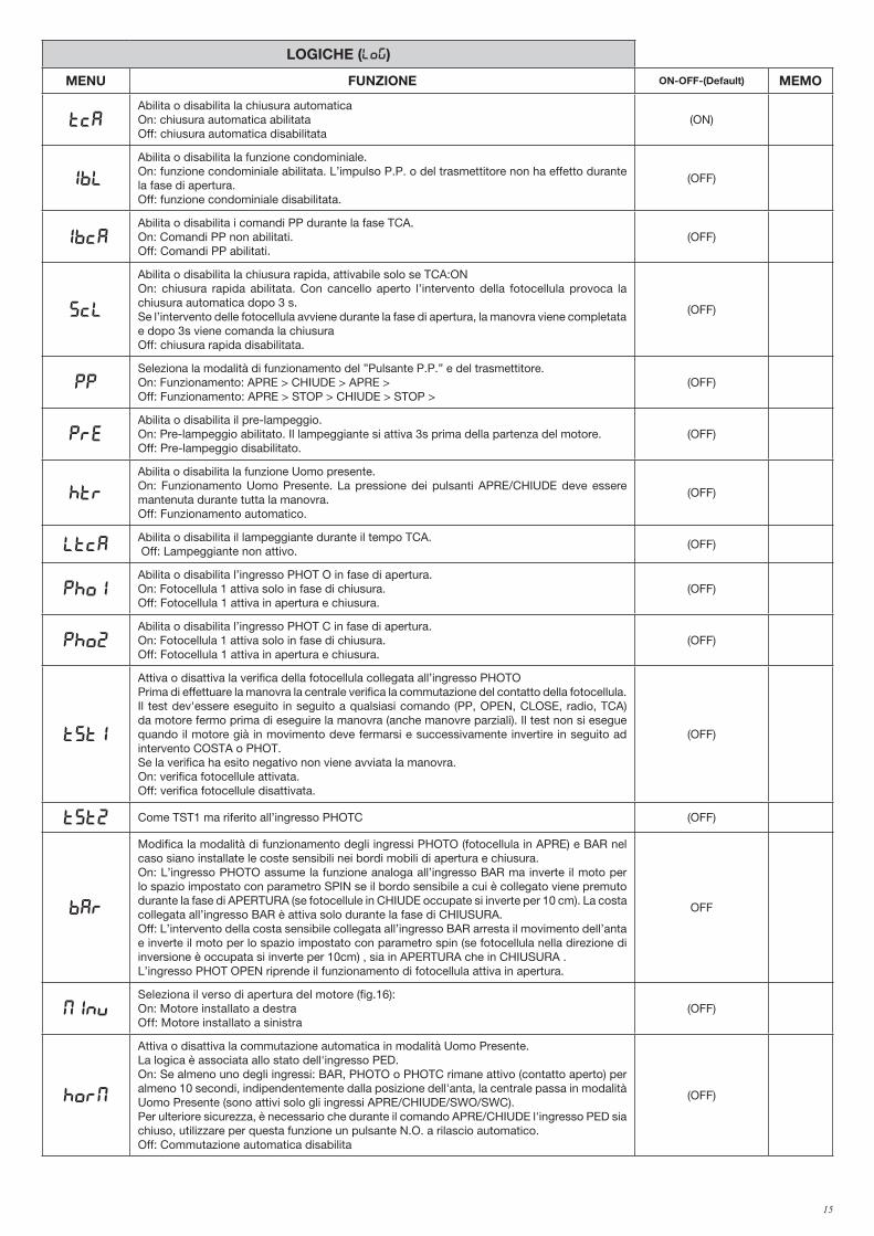
LOGICHE (LOG)
MENU FUNZIONE ON-OFF-(Default) MEMO
TCAAbilita o disabilita la chiusura automaticaOn: chiusura automatica abilitataOff: chiusura automatica disabilitata
(ON)
IBL
Abilita o disabilita la funzione condominiale.On: funzione condominiale abilitata. L’impulso P.P. o del trasmettitore non ha effetto durante la fase di apertura.Off: funzione condominiale disabilitata.
(OFF)
IBCAAbilita o disabilita i comandi PP durante la fase TCA.On: Comandi PP non abilitati.Off: Comandi PP abilitati.
(OFF)
SCL
Abilita o disabilita la chiusura rapida, attivabile solo se TCA:ONOn: chiusura rapida abilitata. Con cancello aperto l’intervento della fotocellula provoca la chiusura automatica dopo 3 s. Se l’intervento delle fotocellula avviene durante la fase di apertura, la manovra viene completata e dopo 3s viene comanda la chiusuraOff: chiusura rapida disabilitata.
(OFF)
PPSeleziona la modalità di funzionamento del ”Pulsante P.P.” e del trasmettitore.On: Funzionamento: APRE > CHIUDE > APRE >Off: Funzionamento: APRE > STOP > CHIUDE > STOP >
(OFF)
PREAbilita o disabilita il pre-lampeggio.On: Pre-lampeggio abilitato. Il lampeggiante si attiva 3s prima della partenza del motore.Off: Pre-lampeggio disabilitato.
(OFF)
HTR
Abilita o disabilita la funzione Uomo presente. On: Funzionamento Uomo Presente. La pressione dei pulsanti APRE/CHIUDE deve essere mantenuta durante tutta la manovra.Off: Funzionamento automatico.
(OFF)
LTCAAbilita o disabilita il lampeggiante durante il tempo TCA. Off: Lampeggiante non attivo.
(OFF)
Pho1Abilita o disabilita l’ingresso PHOT O in fase di apertura.On: Fotocellula 1 attiva solo in fase di chiusura.Off: Fotocellula 1 attiva in apertura e chiusura.
(OFF)
Pho2Abilita o disabilita l’ingresso PHOT C in fase di apertura.On: Fotocellula 1 attiva solo in fase di chiusura.Off: Fotocellula 1 attiva in apertura e chiusura.
(OFF)
tst1
Attiva o disattiva la verifica della fotocellula collegata all’ingresso PHOTOPrima di effettuare la manovra la centrale verifica la commutazione del contatto della fotocellula. Il test dev'essere eseguito in seguito a qualsiasi comando (PP, OPEN, CLOSE, radio, TCA) da motore fermo prima di eseguire la manovra (anche manovre parziali). Il test non si esegue quando il motore già in movimento deve fermarsi e successivamente invertire in seguito ad intervento COSTA o PHOT.Se la verifica ha esito negativo non viene avviata la manovra.On: verifica fotocellule attivata.Off: verifica fotocellule disattivata.
(OFF)
tst2 Come TST1 ma riferito all’ingresso PHOTC (OFF)
bar
Modifica la modalità di funzionamento degli ingressi PHOTO (fotocellula in APRE) e BAR nel caso siano installate le coste sensibili nei bordi mobili di apertura e chiusura.On: L’ingresso PHOTO assume la funzione analoga all’ingresso BAR ma inverte il moto per lo spazio impostato con parametro SPIN se il bordo sensibile a cui è collegato viene premuto durante la fase di APERTURA (se fotocellule in CHIUDE occupate si inverte per 10 cm). La costa collegata all’ingresso BAR è attiva solo durante la fase di CHIUSURA.Off: L’intervento della costa sensibile collegata all’ingresso BAR arresta il movimento dell’anta e inverte il moto per lo spazio impostato con parametro spin (se fotocellula nella direzione di inversione è occupata si inverte per 10cm) , sia in APERTURA che in CHIUSURA .L’ingresso PHOT OPEN riprende il funzionamento di fotocellula attiva in apertura.
OFF
MINVSeleziona il verso di apertura del motore (fig.16):On: Motore installato a destraOff: Motore installato a sinistra
(OFF)
Horm
Attiva o disattiva la commutazione automatica in modalità Uomo Presente.La logica è associata allo stato dell'ingresso PED.On: Se almeno uno degli ingressi: BAR, PHOTO o PHOTC rimane attivo (contatto aperto) per almeno 10 secondi, indipendentemente dalla posizione dell'anta, la centrale passa in modalità Uomo Presente (sono attivi solo gli ingressi APRE/CHIUDE/SWO/SWC). Per ulteriore sicurezza, è necessario che durante il comando APRE/CHIUDE l'ingresso PED sia chiuso, utilizzare per questa funzione un pulsante N.O. a rilascio automatico.Off: Commutazione automatica disabilita
(OFF)
16
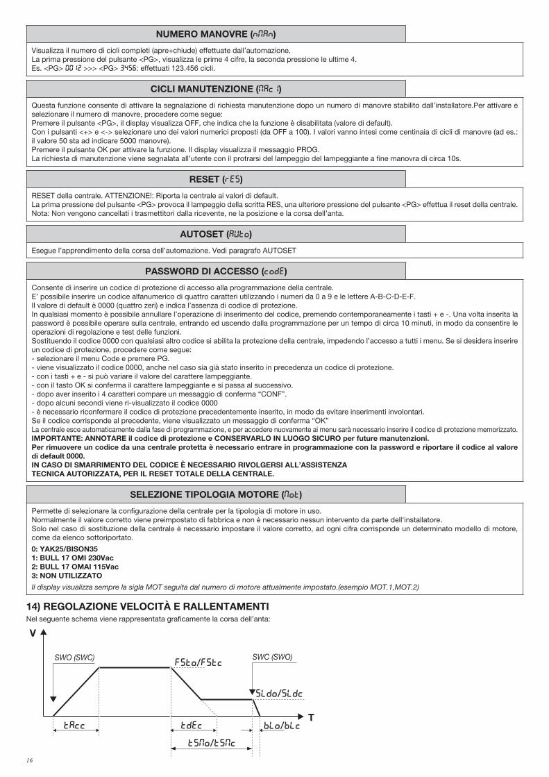
NUMERO MANOVRE (Nman)
Visualizza il numero di cicli completi (apre+chiude) effettuate dall’automazione. La prima pressione del pulsante <PG>, visualizza le prime 4 cifre, la seconda pressione le ultime 4.Es. <PG> 0012 >>> <PG> 3456: effettuati 123.456 cicli.
CICLI MANUTENZIONE (maci)
Questa funzione consente di attivare la segnalazione di richiesta manutenzione dopo un numero di manovre stabilito dall’installatore.Per attivare e selezionare il numero di manovre, procedere come segue:Premere il pulsante <PG>, il display visualizza OFF, che indica che la funzione è disabilitata (valore di default). Con i pulsanti <+> e <-> selezionare uno dei valori numerici proposti (da OFF a 100). I valori vanno intesi come centinaia di cicli di manovre (ad es.: il valore 50 sta ad indicare 5000 manovre).Premere il pulsante OK per attivare la funzione. Il display visualizza il messaggio PROG.La richiesta di manutenzione viene segnalata all’utente con il protrarsi del lampeggio del lampeggiante a fine manovra di circa 10s.
RESET (RES)
RESET della centrale. ATTENZIONE!: Riporta la centrale ai valori di default.La prima pressione del pulsante <PG> provoca il lampeggio della scritta RES, una ulteriore pressione del pulsante <PG> effettua il reset della centrale.Nota: Non vengono cancellati i trasmettitori dalla ricevente, ne la posizione e la corsa dell’anta.
AUTOSET (AUTO)
Esegue l’apprendimento della corsa dell’automazione. Vedi paragrafo AUTOSET
PASSWORD DI ACCESSO (CODE)
Consente di inserire un codice di protezione di accesso alla programmazione della centrale.E’ possibile inserire un codice alfanumerico di quattro caratteri utilizzando i numeri da 0 a 9 e le lettere A-B-C-D-E-F.Il valore di default è 0000 (quattro zeri) e indica l’assenza di codice di protezione.In qualsiasi momento è possibile annullare l’operazione di inserimento del codice, premendo contemporaneamente i tasti + e -. Una volta inserita la password è possibile operare sulla centrale, entrando ed uscendo dalla programmazione per un tempo di circa 10 minuti, in modo da consentire le operazioni di regolazione e test delle funzioni.Sostituendo il codice 0000 con qualsiasi altro codice si abilita la protezione della centrale, impedendo l’accesso a tutti i menu. Se si desidera inserire un codice di protezione, procedere come segue:- selezionare il menu Code e premere PG.- viene visualizzato il codice 0000, anche nel caso sia già stato inserito in precedenza un codice di protezione.- con i tasti + e - si può variare il valore del carattere lampeggiante.- con il tasto OK si conferma il carattere lampeggiante e si passa al successivo.- dopo aver inserito i 4 caratteri compare un messaggio di conferma “CONF”.- dopo alcuni secondi viene ri-visualizzato il codice 0000- è necessario riconfermare il codice di protezione precedentemente inserito, in modo da evitare inserimenti involontari.Se il codice corrisponde al precedente, viene visualizzato un messaggio di conferma “OK”La centrale esce automaticamente dalla fase di programmazione, e per accedere nuovamente ai menu sarà necessario inserire il codice di protezione memorizzato.IMPORTANTE: ANNOTARE il codice di protezione e CONSERVARLO IN LUOGO SICURO per future manutenzioni. Per rimuovere un codice da una centrale protetta è necessario entrare in programmazione con la password e riportare il codice al valore di default 0000.IN CASO DI SMARRIMENTO DEL CODICE È NECESSARIO RIVOLGERSI ALL’ASSISTENZA TECNICA AUTORIZZATA, PER IL RESET TOTALE DELLA CENTRALE.
SELEZIONE TIPOLOGIA MOTORE (MOT)
Permette di selezionare la configurazione della centrale per la tipologia di motore in uso.Normalmente il valore corretto viene preimpostato di fabbrica e non è necessario nessun intervento da parte dell'installatore.Solo nel caso di sostituzione della centrale è necessario impostare il valore corretto, ad ogni cifra corrisponde un determinato modello di motore, come da elenco sottoriportato.
0: YAK25/BISON351: BULL 17 OMI 230Vac2: BULL 17 OMAI 115Vac3: NON UTILIZZATO
Il display visualizza sempre la sigla MOT seguita dal numero di motore attualmente impostato.(esempio MOT.1,MOT.2)
14) REGOLAZIONE VELOCITÀ E RALLENTAMENTINel seguente schema viene rappresentata graficamente la corsa dell’anta:
V
T
FSTo/fstc
sldo/SldC
BLo/blcTAcc Tdec
TSMo/tsmc
SWO (SWC) SWC (SWO)
V
Ttbr
stopphotbar
17
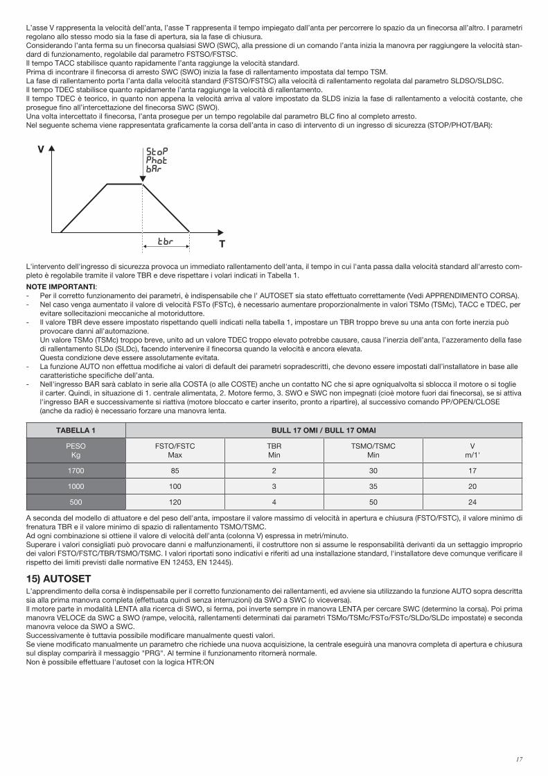
L’asse V rappresenta la velocità dell’anta, l’asse T rappresenta il tempo impiegato dall’anta per percorrere lo spazio da un finecorsa all’altro. I parametri regolano allo stesso modo sia la fase di apertura, sia la fase di chiusura.Considerando l’anta ferma su un finecorsa qualsiasi SWO (SWC), alla pressione di un comando l’anta inizia la manovra per raggiungere la velocità stan-dard di funzionamento, regolabile dal parametro FSTSO/FSTSC. Il tempo TACC stabilisce quanto rapidamente l’anta raggiunge la velocità standard.Prima di incontrare il finecorsa di arresto SWC (SWO) inizia la fase di rallentamento impostata dal tempo TSM.La fase di rallentamento porta l’anta dalla velocità standard (FSTSO/FSTSC) alla velocità di rallentamento regolata dal parametro SLDSO/SLDSC.Il tempo TDEC stabilisce quanto rapidamente l’anta raggiunge la velocità di rallentamento.Il tempo TDEC è teorico, in quanto non appena la velocità arriva al valore impostato da SLDS inizia la fase di rallentamento a velocità costante, che prosegue fino all’intercettazione del finecorsa SWC (SWO).Una volta intercettato il finecorsa, l’anta prosegue per un tempo regolabile dal parametro BLC fino al completo arresto.Nel seguente schema viene rappresentata graficamente la corsa dell’anta in caso di intervento di un ingresso di sicurezza (STOP/PHOT/BAR):
V
T
FSTo/fstc
sldo/SldC
BLo/blcTAcc Tdec
TSMo/tsmc
SWO (SWC) SWC (SWO)
V
Ttbr
stopphotbar
L'intervento dell'ingresso di sicurezza provoca un immediato rallentamento dell'anta, il tempo in cui l'anta passa dalla velocità standard all'arresto com-pleto è regolabile tramite il valore TBR e deve rispettare i volari indicati in Tabella 1.
NOTE IMPORTANTI:- Per il corretto funzionamento dei parametri, è indispensabile che l’ AUTOSET sia stato effettuato correttamente (Vedi APPRENDIMENTO CORSA).- Nel caso venga aumentato il valore di velocità FSTo (FSTc), è necessario aumentare proporzionalmente in valori TSMo (TSMc), TACC e TDEC, per evitare sollecitazioni meccaniche al motoriduttore.- Il valore TBR deve essere impostato rispettando quelli indicati nella tabella 1, impostare un TBR troppo breve su una anta con forte inerzia può provocare danni all'automazione. Un valore TSMo (TSMc) troppo breve, unito ad un valore TDEC troppo elevato potrebbe causare, causa l’inerzia dell’anta, l’azzeramento della fase di rallentamento SLDo (SLDc), facendo intervenire il finecorsa quando la velocità e ancora elevata. Questa condizione deve essere assolutamente evitata.- La funzione AUTO non effettua modifiche ai valori di default dei parametri sopradescritti, che devono essere impostati dall’installatore in base alle caratteristiche specifiche dell’anta.- Nell'ingresso BAR sarà cablato in serie alla COSTA (o alle COSTE) anche un contatto NC che si apre ogniqualvolta si sblocca il motore o si toglie il carter. Quindi, in situazione di 1. centrale alimentata, 2. Motore fermo, 3. SWO e SWC non impegnati (cioè motore fuori dai finecorsa), se si attiva l'ingresso BAR e successivamente si riattiva (motore bloccato e carter inserito, pronto a ripartire), al successivo comando PP/OPEN/CLOSE (anche da radio) è necessario forzare una manovra lenta.
TABELLA 1 BULL 17 OMI / BULL 17 OMAI
PESOKg
FSTO/FSTCMax
TBRMin
TSMO/TSMCMin
Vm/1'
1700 85 2 30 17
1000 100 3 35 20
500 120 4 50 24
A seconda del modello di attuatore e del peso dell'anta, impostare il valore massimo di velocità in apertura e chiusura (FSTO/FSTC), il valore minimo di frenatura TBR e il valore minimo di spazio di rallentamento TSMO/TSMC. Ad ogni combinazione si ottiene il valore di velocità dell'anta (colonna V) espressa in metri/minuto.Superare i valori consigliati può provocare danni e malfunzionamenti, il costruttore non si assume le responsabilità derivanti da un settaggio improprio dei valori FSTO/FSTC/TBR/TSMO/TSMC. I valori riportati sono indicativi e riferiti ad una installazione standard, l'installatore deve comunque verificare il rispetto dei limiti previsti dalle normative EN 12453, EN 12445).
15) AUTOSETL’apprendimento della corsa è indispensabile per il corretto funzionamento dei rallentamenti, ed avviene sia utilizzando la funzione AUTO sopra descritta sia alla prima manovra completa (effettuata quindi senza interruzioni) da SWO a SWC (o viceversa).Il motore parte in modalità LENTA alla ricerca di SWO, si ferma, poi inverte sempre in manovra LENTA per cercare SWC (determino la corsa). Poi prima manovra VELOCE da SWC a SWO (rampe, velocità, rallentamenti determinati dai parametri TSMo/TSMc/FSTo/FSTc/SLDo/SLDc impostate) e seconda manovra veloce da SWO a SWC.Successivamente è tuttavia possibile modificare manualmente questi valori.Se viene modificato manualmente un parametro che richiede una nuova acquisizione, la centrale eseguirà una manovra completa di apertura e chiusura sul display comparirà il messaggio "PRG". Al termine il funzionamento ritornerà normale.Non è possibile effettuare l'autoset con la logica HTR:ON
18
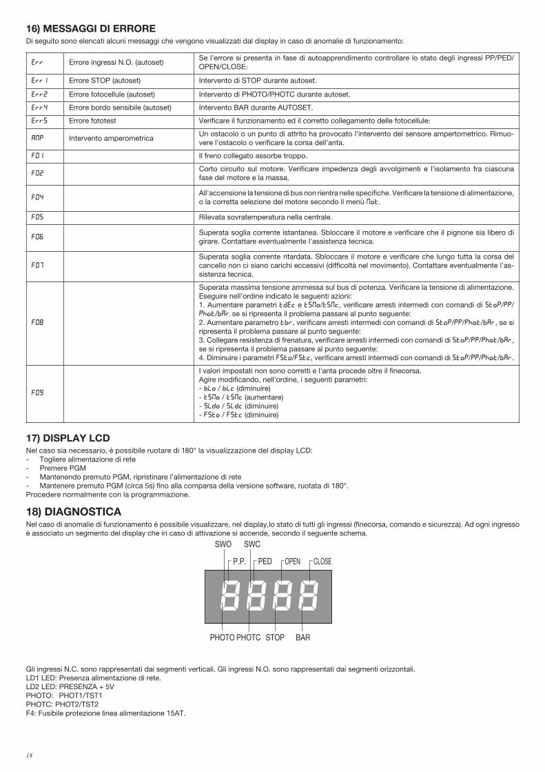
16) MESSAGGI DI ERROREDi seguito sono elencati alcuni messaggi che vengono visualizzati dal display in caso di anomalie di funzionamento:
err Errore ingressi N.O. (autoset)Se l’errore si presenta in fase di autoapprendimento controllare lo stato degli ingressi PP/PED/OPEN/CLOSE.
Err1 Errore STOP (autoset) Intervento di STOP durante autoset.
Err2 Errore fotocellule (autoset) Intervento di PHOTO/PHOTC durante autoset.
Err4 Errore bordo sensibile (autoset) Intervento BAR durante AUTOSET.
Err5 Errore fototest Verificare il funzionamento ed il corretto collegamento delle fotocellule.
amp Intervento amperometricaUn ostacolo o un punto di attrito ha provocato l’intervento del sensore ampertometrico. Rimuo-vere l’ostacolo o verificare la corsa dell’anta.
F01 Il freno collegato assorbe troppo.
F02Corto circuito sul motore. Verificare impedenza degli avvolgimenti e l'isolamento fra ciascuna fase del motore e la massa.
F04All'accensione la tensione di bus non rientra nelle specifiche. Verificare la tensione di alimentazione, o la corretta selezione del motore secondo il menù MOT.
F05 Rilevata sovratemperatura nella centrale.
F06Superata soglia corrente istantanea. Sbloccare il motore e verificare che il pignone sia libero di girare. Contattare eventualmente l'assistenza tecnica.
F07
Superata soglia corrente ritardata. Sbloccare il motore e verificare che lungo tutta la corsa del cancello non ci siano carichi eccessivi (difficoltà nel movimento). Contattare eventualmente l'as-sistenza tecnica.
F08
Superata massima tensione ammessa sul bus di potenza. Verificare la tensione di alimentazione. Eseguire nell'ordine indicato le seguenti azioni:1. Aumentare parametri TDEC e TSMO/TSMC, verificare arresti intermedi con comandi di STOP/PP/PHOT/BAR, se si ripresenta il problema passare al punto seguente:2. Aumentare parametro TBR, verificare arresti intermedi con comandi di STOP/PP/PHOT/BAR, se si ripresenta il problema passare al punto seguente:3. Collegare resistenza di frenatura, verificare arresti intermedi con comandi di STOP/PP/PHOT/BAR, se si ripresenta il problema passare al punto seguente:4. Diminuire i parametri FSTO/FSTC, verificare arresti intermedi con comandi di STOP/PP/PHOT/BAR.
F09
I valori impostati non sono corretti e l'anta procede oltre il finecorsa.Agire modificando, nell'ordine, i seguenti parametri:- blo / blc (diminuire)- tsmo / tsmc (aumentare)- sldo / sldc (diminuire)- fsto / fstc (diminuire)
17) DISPLAY LCDNel caso sia necessario, è possibile ruotare di 180° la visualizzazione del display LCD:- Togliere alimentazione di rete- Premere PGM- Mantenendo premuto PGM, ripristinare l’alimentazione di rete- Mantenere premuto PGM (circa 5s) fino alla comparsa della versione software, ruotata di 180°. Procedere normalmente con la programmazione.
18) DIAGNOSTICANel caso di anomalie di funzionamento è possibile visualizzare, nel display,lo stato di tutti gli ingressi (finecorsa, comando e sicurezza). Ad ogni ingresso è associato un segmento del display che in caso di attivazione si accende, secondo il seguente schema.
PHOTO
SWC
STOP
SWO
PHOTC BAR
P.P. PED OPEN CLOSE
Gli ingressi N.C. sono rappresentati dai segmenti verticali. Gli ingressi N.O. sono rappresentati dai segmenti orizzontali.LD1 LED: Presenza alimentazione di rete.LD2 LED: PRESENZA + 5VPHOTO: PHOT1/TST1PHOTC: PHOT2/TST2F4: Fusibile protezione linea alimentazione 15AT.
19
19) MANUTENZIONELa seguente tabella serve per registrare gli interventi di manutenzione, miglioramento o riparazione effettuati dal tecnico specializzato.
Data _ _ _ _ _ _ _ _ _ _ _ _ _ _ _ _ _ _ _ _ _ _ _ _ _ _ _ _ _ _ _ _ Firma Tecnico _ _ _ _ _ _ _ _ _ _ _ _ _ _ _ _ _ _ _ _ _ _ _ _ _ _ _ Timbro
Descrizione intervento
_ _ _ _ _ _ _ _ _ _ _ _ _ _ _ _ _ _ _ _ _ _ _ _ _ _ _ _ _ _ _ _ _ _ _ _ _ _ _ _ _ _ _ _ _ _ _ _ _ _ _ _ _ _ _ _ _ _ _ _ _ _ _ _ _ _ _ _ _ _ _ _ _
_ _ _ _ _ _ _ _ _ _ _ _ _ _ _ _ _ _ _ _ _ _ _ _ _ _ _ _ _ _ _ _ _ _ _ _ _ _ _ _ _ _ _ _ _ _ _ _ _ _ _ _ _ _ _ _ _ _ _ _ _ _ _ _ _ _ _ _ _ _ _ _ _
Data _ _ _ _ _ _ _ _ _ _ _ _ _ _ _ _ _ _ _ _ _ _ _ _ _ _ _ _ _ _ _ _ Firma Tecnico _ _ _ _ _ _ _ _ _ _ _ _ _ _ _ _ _ _ _ _ _ _ _ _ _ _ _ Timbro
Descrizione intervento_ _ _ _ _ _ _ _ _ _ _ _ _ _ _ _ _ _ _ _ _ _ _ _ _ _ _ _ _ _ _ _ _ _ _ _ _ _ _ _ _ _ _ _ _ _ _ _ _ _ _ _ _ _ _ _ _ _ _ _ _ _ _ _ _ _ _ _ _ _ _ _ _ _ _ _ _ _ _ _ _ _ _ _ _ _ _ _ _ _ _ _ _ _ _ _ _ _ _ _ _ _ _ _ _ _ _ _ _ _ _ _ _ _ _ _ _ _ _ _ _ _ _ _ _ _ _ _ _ _ _ _ _ _ _ _ _ _ _ _ _ _ _ _ _ _
Data _ _ _ _ _ _ _ _ _ _ _ _ _ _ _ _ _ _ _ _ _ _ _ _ _ _ _ _ _ _ _ _ Firma Tecnico _ _ _ _ _ _ _ _ _ _ _ _ _ _ _ _ _ _ _ _ _ _ _ _ _ _ _ Timbro
Descrizione intervento
_ _ _ _ _ _ _ _ _ _ _ _ _ _ _ _ _ _ _ _ _ _ _ _ _ _ _ _ _ _ _ _ _ _ _ _ _ _ _ _ _ _ _ _ _ _ _ _ _ _ _ _ _ _ _ _ _ _ _ _ _ _ _ _ _ _ _ _ _ _ _ _ _
_ _ _ _ _ _ _ _ _ _ _ _ _ _ _ _ _ _ _ _ _ _ _ _ _ _ _ _ _ _ _ _ _ _ _ _ _ _ _ _ _ _ _ _ _ _ _ _ _ _ _ _ _ _ _ _ _ _ _ _ _ _ _ _ _ _ _ _ _ _ _ _ _
Data _ _ _ _ _ _ _ _ _ _ _ _ _ _ _ _ _ _ _ _ _ _ _ _ _ _ _ _ _ _ _ _ Firma Tecnico _ _ _ _ _ _ _ _ _ _ _ _ _ _ _ _ _ _ _ _ _ _ _ _ _ _ _ Timbro
Descrizione intervento
_ _ _ _ _ _ _ _ _ _ _ _ _ _ _ _ _ _ _ _ _ _ _ _ _ _ _ _ _ _ _ _ _ _ _ _ _ _ _ _ _ _ _ _ _ _ _ _ _ _ _ _ _ _ _ _ _ _ _ _ _ _ _ _ _ _ _ _ _ _ _ _ _
_ _ _ _ _ _ _ _ _ _ _ _ _ _ _ _ _ _ _ _ _ _ _ _ _ _ _ _ _ _ _ _ _ _ _ _ _ _ _ _ _ _ _ _ _ _ _ _ _ _ _ _ _ _ _ _ _ _ _ _ _ _ _ _ _ _ _ _ _ _ _ _ _
20
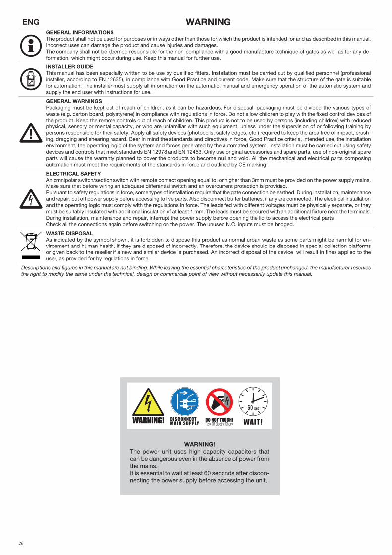
ENG WARNINGGENERAL INFORMATIONSThe product shall not be used for purposes or in ways other than those for which the product is intended for and as described in this manual. Incorrect uses can damage the product and cause injuries and damages.The company shall not be deemed responsible for the non-compliance with a good manufacture technique of gates as well as for any de-formation, which might occur during use. Keep this manual for further use.
INSTALLER GUIDEThis manual has been especially written to be use by qualified fitters. Installation must be carried out by qualified personnel (professional installer, according to EN 12635), in compliance with Good Practice and current code. Make sure that the structure of the gate is suitable for automation. The installer must supply all information on the automatic, manual and emergency operation of the automatic system and supply the end user with instructions for use.
GENERAL WARNINGSPackaging must be kept out of reach of children, as it can be hazardous. For disposal, packaging must be divided the various types of waste (e.g. carton board, polystyrene) in compliance with regulations in force. Do not allow children to play with the fixed control devices of the product. Keep the remote controls out of reach of children. This product is not to be used by persons (including children) with reduced physical, sensory or mental capacity, or who are unfamiliar with such equipment, unless under the supervision of or following training by persons responsible for their safety. Apply all safety devices (photocells, safety edges, etc.) required to keep the area free of impact, crush-ing, dragging and shearing hazard. Bear in mind the standards and directives in force, Good Practice criteria, intended use, the installation environment, the operating logic of the system and forces generated by the automated system. Installation must be carried out using safety devices and controls that meet standards EN 12978 and EN 12453. Only use original accessories and spare parts, use of non-original spare parts will cause the warranty planned to cover the products to become null and void. All the mechanical and electrical parts composing automation must meet the requirements of the standards in force and outlined by CE marking.
ELECTRICAL SAFETYAn omnipolar switch/section switch with remote contact opening equal to, or higher than 3mm must be provided on the power supply mains.Make sure that before wiring an adequate differential switch and an overcurrent protection is provided.Pursuant to safety regulations in force, some types of installation require that the gate connection be earthed. During installation, maintenance and repair, cut off power supply before accessing to live parts. Also disconnect buffer batteries, if any are connected. The electrical installation and the operating logic must comply with the regulations in force. The leads fed with different voltages must be physically separate, or they must be suitably insulated with additional insulation of at least 1 mm. The leads must be secured with an additional fixture near the terminals.During installation, maintenance and repair, interrupt the power supply before opening the lid to access the electrical partsCheck all the connections again before switching on the power. The unused N.C. inputs must be bridged.
WASTE DISPOSALAs indicated by the symbol shown, it is forbidden to dispose this product as normal urban waste as some parts might be harmful for en-vironment and human health, if they are disposed of incorrectly. Therefore, the device should be disposed in special collection platforms or given back to the reseller if a new and similar device is purchased. An incorrect disposal of the device will result in fines applied to the user, as provided for by regulations in force.
Descriptions and figures in this manual are not binding. While leaving the essential characteristics of the product unchanged, the manufacturer reserves the right to modify the same under the technical, design or commercial point of view without necessarily update this manual.
WARNING!The power unit uses high capacity capacitors that can be dangerous even in the absence of power from the mains.It is essential to wait at least 60 seconds after discon-necting the power supply before accessing the unit.
Read Instructions
DO NOT TOUCH!DISCONNECT M A I N S U P P LY WAIT!
60 sec.
WARNING!
F8369256
Etichetta WARNING: Formato 55x50mm
stampa su PVC adesivo4 colori
Read Instructions
DO NOT TOUCH!DISCONNECT M A I N S U P P LY WAIT!
60 sec.
WARNING!
F8369256
Etichetta WARNING: Formato 55x50mm
stampa su PVC adesivo4 colori
21
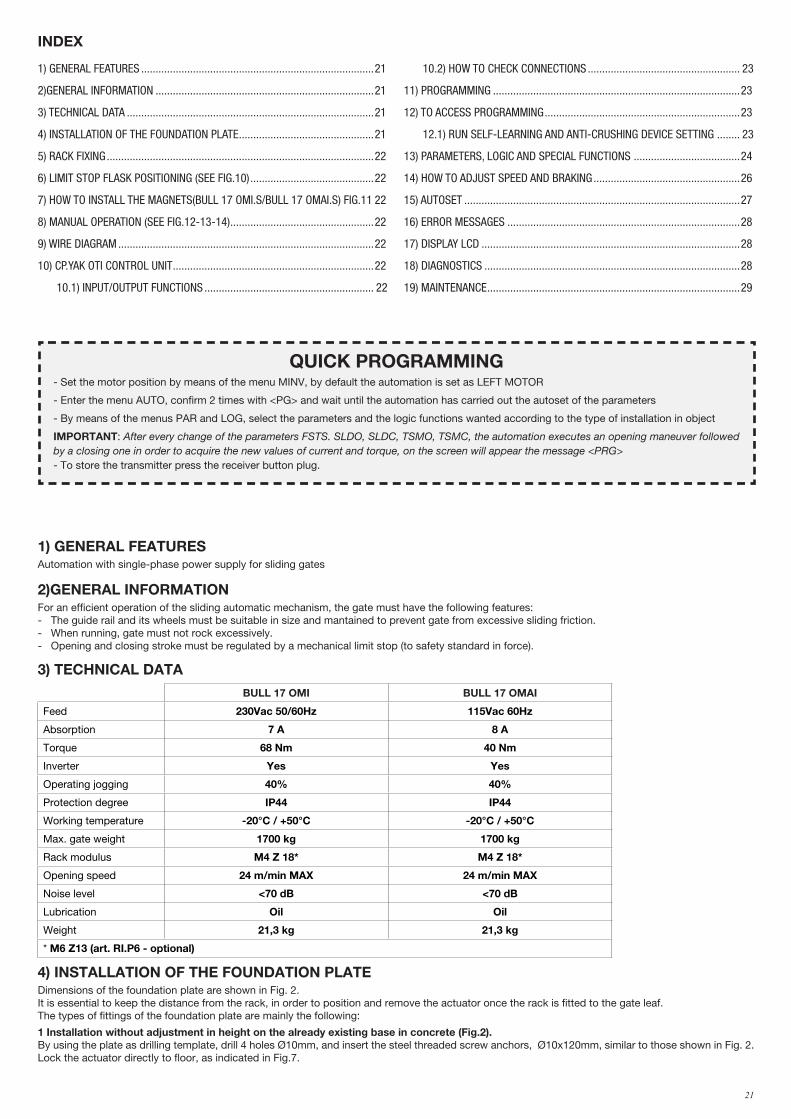
1) GENERAL FEATURESAutomation with single-phase power supply for sliding gates
2)GENERAL INFORMATIONFor an efficient operation of the sliding automatic mechanism, the gate must have the following features:- The guide rail and its wheels must be suitable in size and mantained to prevent gate from excessive sliding friction.- When running, gate must not rock excessively.- Opening and closing stroke must be regulated by a mechanical limit stop (to safety standard in force).
3) TECHNICAL DATA
BULL 17 OMI BULL 17 OMAI
Feed 230Vac 50/60Hz 115Vac 60Hz
Absorption 7 A 8 A
Torque 68 Nm 40 Nm
Inverter Yes Yes
Operating jogging 40% 40%
Protection degree IP44 IP44
Working temperature -20°C / +50°C -20°C / +50°C
Max. gate weight 1700 kg 1700 kg
Rack modulus M4 Z 18* M4 Z 18*
Opening speed 24 m/min MAX 24 m/min MAX
Noise level <70 dB <70 dB
Lubrication Oil Oil
Weight 21,3 kg 21,3 kg
* M6 Z13 (art. RI.P6 - optional)
4) INSTALLATION OF THE FOUNDATION PLATEDimensions of the foundation plate are shown in Fig. 2.It is essential to keep the distance from the rack, in order to position and remove the actuator once the rack is fitted to the gate leaf.The types of fittings of the foundation plate are mainly the following:
1 Installation without adjustment in height on the already existing base in concrete (Fig.2). By using the plate as drilling template, drill 4 holes Ø10mm, and insert the steel threaded screw anchors, Ø10x120mm, similar to those shown in Fig. 2.Lock the actuator directly to floor, as indicated in Fig.7.
1) GENERAL FEATURES .................................................................................21
2)GENERAL INFORMATION ............................................................................21
3) TECHNICAL DATA ......................................................................................21
4) INSTALLATION OF THE FOUNDATION PLATE ...............................................21
5) RACK FIXING .............................................................................................22
6) LIMIT STOP FLASK POSITIONING (SEE FIG.10) ...........................................22
7) HOW TO INSTALL THE MAGNETS(BULL 17 OMI.S/BULL 17 OMAI.S) FIG.11 22
8) MANUAL OPERATION (SEE FIG.12-13-14) ..................................................22
9) WIRE DIAGRAM .........................................................................................22
10) CP.YAK OTI CONTROL UNIT ......................................................................22
10.1) INPUT/OUTPUT FUNCTIONS ........................................................... 22
10.2) HOW TO CHECK CONNECTIONS ..................................................... 23
11) PROGRAMMING ......................................................................................23
12) TO ACCESS PROGRAMMING ....................................................................23
12.1) RUN SELF-LEARNING AND ANTI-CRUSHING DEVICE SETTING ........ 23
13) PARAMETERS, LOGIC AND SPECIAL FUNCTIONS .....................................24
14) HOW TO ADJUST SPEED AND BRAKING ...................................................26
15) AUTOSET ................................................................................................27
16) ERROR MESSAGES .................................................................................28
17) DISPLAY LCD ..........................................................................................28
18) DIAGNOSTICS .........................................................................................28
19) MAINTENANCE ........................................................................................29
INDEX
QUICK PROGRAMMING- Set the motor position by means of the menu MINV, by default the automation is set as LEFT MOTOR
- Enter the menu AUTO, confirm 2 times with <PG> and wait until the automation has carried out the autoset of the parameters
- By means of the menus PAR and LOG, select the parameters and the logic functions wanted according to the type of installation in object
IMPORTANT: After every change of the parameters FSTS. SLDO, SLDC, TSMO, TSMC, the automation executes an opening maneuver followed by a closing one in order to acquire the new values of current and torque, on the screen will appear the message <PRG> - To store the transmitter press the receiver button plug.
22
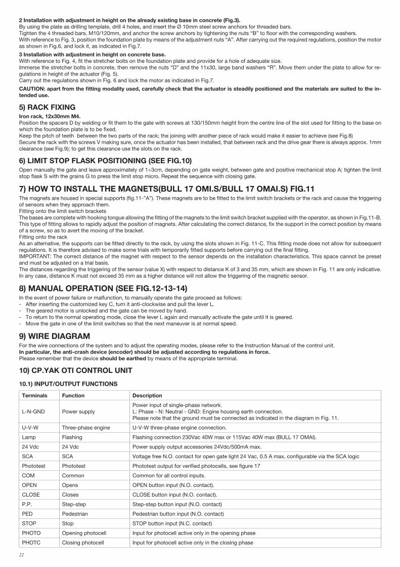
2 Installation with adjustment in height on the already existing base in concrete (Fig.3). By using the plate as drilling template, drill 4 holes, and insert the Ø 10mm steel screw anchors for threaded bars.Tighten the 4 threaded bars, M10/120mm, and anchor the screw anchors by tightening the nuts “B” to floor with the corresponding washers.With reference to Fig. 3, position the foundation plate by means of the adjustment nuts “A”. After carrying out the required regulations, position the motor as shown in Fig.6, and lock it, as indicated in Fig.7.
3 Installation with adjustment in height on concrete base. With reference to Fig. 4, fit the stretcher bolts on the foundation plate and provide for a hole of adequate size.Immerse the stretcher bolts in concrete, then remove the nuts “D” and the 11x30, large band washers “R”. Move them under the plate to allow for re-gulations in height of the actuator (Fig. 5).Carry out the regulations shown in Fig. 6 and lock the motor as indicated in Fig.7.
CAUTION: apart from the fitting modality used, carefully check that the actuator is steadily positioned and the materials are suited to the in-tended use.
5) RACK FIXINGIron rack, 12x30mm M4.Position the spacers D by welding or fit them to the gate with screws at 130/150mm height from the centre line of the slot used for fitting to the base on which the foundation plate is to be fixed.Keep the pitch of teeth between the two parts of the rack; the joining with another piece of rack would make it easier to achieve (see Fig.8)Secure the rack with the screws V making sure, once the actuator has been installed, that between rack and the drive gear there is always approx. 1mm clearance (see Fig.9); to get this clearance use the slots on the rack.
6) LIMIT STOP FLASK POSITIONING (SEE FIG.10)Open manually the gate and leave approximately of 1÷3cm, depending on gate weight, between gate and positive mechanical stop A; tighten the limit stop flask S with the grains G to press the limit stop micro. Repeat the sequence with closing gate.
7) HOW TO INSTALL THE MAGNETS(BULL 17 OMI.S/BULL 17 OMAI.S) FIG.11The magnets are housed in special supports (fig.11-”A”). These magnets are to be fitted to the limit switch brackets or the rack and cause the triggering of sensors when they approach them.Fitting onto the limit switch bracketsThe bases are complete with hooking tongue allowing the fitting of the magnets to the limit switch bracket supplied with the operator, as shown in Fig.11-B.This type of fitting allows to rapidly adjust the position of magnets. After calculating the correct distance, fix the support in the correct position by means of a screw, so as to avert the moving of the bracket.Fitting onto the rack As an alternative, the supports can be fitted directly to the rack, by using the slots shown in Fig. 11-C. This fitting mode does not allow for subsequent regulations. It is therefore advised to make some trials with temporarily fitted supports before carrying out the final fitting.IMPORTANT: The correct distance of the magnet with respect to the sensor depends on the installation characteristics. This space cannot be preset and must be adjusted on a trial basis. The distances regarding the triggering of the sensor (value X) with respect to distance K of 3 and 35 mm, which are shown in Fig. 11 are only indicative.In any case, distance K must not exceed 35 mm as a higher distance will not allow the triggering of the magnetic sensor.
8) MANUAL OPERATION (SEE FIG.12-13-14)In the event of power failure or malfunction, to manually operate the gate proceed as follows:- After inserting the customized key C, turn it anti-clockwise and pull the lever L.- The geared motor is unlocked and the gate can be moved by hand.- To return to the normal operating mode, close the lever L again and manually activate the gate until it is geared.- Move the gate in one of the limit switches so that the next maneuver is at normal speed.
9) WIRE DIAGRAMFor the wire connections of the system and to adjust the operating modes, please refer to the Instruction Manual of the control unit.In particular, the anti-crash device (encoder) should be adjusted according to regulations in force.Please remember that the device should be earthed by means of the appropriate terminal.
10) CP.YAK OTI CONTROL UNIT
10.1) INPUT/OUTPUT FUNCTIONS
Terminals Function Description
L-N-GND Power supplyPower input of single-phase network.L: Phase - N: Neutral - GND: Engine housing earth connection.Please note that the ground must be connected as indicated in the diagram in Fig. 11.
U-V-W Three-phase engine U-V-W three-phase engine connection.
Lamp Flashing Flashing connection 230Vac 40W max or 115Vac 40W max (BULL 17 OMAI).
24 Vdc 24 Vdc Power supply output accessories 24Vdc/500mA max.
SCA SCA Voltage free N.O. contact for open gate light 24 Vac, 0.5 A max, configurable via the SCA logic
Phototest Phototest Phototest output for verified photocells, see figure 17
COM Common Common for all control inputs.
OPEN Opens OPEN button input (N.O. contact).
CLOSE Closes CLOSE button input (N.O. contact).
P.P. Step-step Step-step button input (N.O. contact)
PED Pedestrian Pedestrian button input (N.O. contact)
STOP Stop STOP button input (N.C. contact)
PHOTO Opening photocell Input for photocell active only in the opening phase
PHOTC Closing photocell Input for photocell active only in the closing phase

23
COM Common Common for limit switch.
SWC Closing Limit Switch CLOSING limit switch input (N.C. contact)
SWO Opening Limit Switch OPENING limit switch input (N.C. contact)
BAR Sensing safety edge
Sensing edge contact inputResistive safety edge (8K2): JP1 "BAR" closedMechanical safety edge (N.C.): JP1 "BAR" openThe intervention of the safety edge stops the movement of the gate and reverses for approximately 3s.Note: this entry is connected the safety transformer mounted on the hand release lever that prevents any maneuver if the motor released.The sensitive edge must be connected in series to this Microswitch, as shown in Figure 21
RADIO Radio receiver Quick connector for plug radio receiver.
2CH Second channel N.O. output of the second radio channel of the radio receiver. (max 24Vac/dc 1A)
BRAKE Brake ResistanceInput for braking current dissipation resistanceThe resistance is only used on 230V BULL 17 OMI
P3 Not used
CON1 Not used
J7 Not used
J8 Not used
SW1 Dip1, Dip2 Keep it ON
U1CONFIGURATION MEMORY
E-Eprom extractable memory. it contains all the configurations of the unit (logical, parameters, etc.), excluding radio transmitters. In case of failure it is possible to extract the E-Eprom and insert it in a different unit, thus avoiding reprogramming.
10.2) HOW TO CHECK CONNECTIONS1) Cut off power supply.2) Manually release the door/gate and push it for about half stoke. Lock the door again.3) Restore power supply.4) Send a step-by-step command through push-button <-> on the control unit (LCD display off). To stop the door/gate press <-> once more. 5) The door/gate should open. If not, set the MINV logics to change the opening direction (default MINV=OFF) Engine installed to the left.
11) PROGRAMMINGThe programming of the various functions of the control unit is carried out using the LCD display on the control unit and setting the desired values in the programming menus described below.The parameters menu allows you to assign a numerical value to a function, in the same way as a regulating trimmer.The logic menu allows you to activate or deactivate a function, in the same way as setting a dip-switch.Other special functions follow the parameters and logic menus and may vary depending on the type of control unit or the software release.
12) TO ACCESS PROGRAMMING1 - Press the button <PG>, the display goes to the first menu, Parameters “PAR”. 2 - With the <+> or <-> button, select the menu you want.3 - Press the button <PG>, the display shows the first function available on the menu.4 - With the <+> or <-> button, select the function you want.5 - Press the button <PG>, the display shows the value currently set for the function selected.6 - With the <+> or <-> button, select the value you intend to assign to the function.7 - Press the button <PG>, the display shows the signal “PRG” which indicates that programming has been completed.
12.1) RUN SELF-LEARNING AND ANTI-CRUSHING DEVICE SETTING When operator assembly and wiring is completed, parameters and logic are programmed, self learning allows the operator to learn the stroke and torque.Enter menu Auto and press the button < PG >, PUSH will be displayed. Press again the button < PG >: self-learning is beginning: PRG will be displayed, and the control panel completes some opening/closing cycles. When the procedure is completed OK will be displayed. This procedure can be followed from any position of the gate/door leaf and can be stopped at any moment by pressing keys <+> and <-> at the same time, or through the activation of STOP/PHO/PHA/BAR/PP/PED inputs.If the procedure is not successful, the wording ERR appears. Check that no obstacles or frictions are present.After the AUTOSET procedure it is necessary to check the value of the operating forces according to the European Standards EN12445 and EN12453. If the value of the force is too high it is mandatory to install a safety edge which complies to the standard EN12978.Check the value of the operative forces in accordance with EN12445 and EN12453 at the end of the autoset phase. If the value of the force is too high install an edge compliant with EN12978.
Notes: Pressing <-> with the display turned off means an impulse of P.P. Simultaneously pressing <+> and <-> from inside a function menu allows you to return to the previous menu without making any changes. Hold down the <+> key or the <-> key to accelerate the increase/decrease of the values.After waiting 30s the control unit quits programming mode and switches off the display.
24
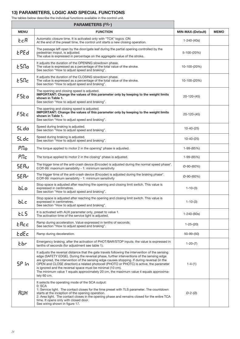
13) PARAMETERS, LOGIC AND SPECIAL FUNCTIONS The tables below describe the individual functions available in the control unit.
PARAMETERS (PAR)
MENU FUNCTION MIN-MAX-(Default) MEMO
TCAAutomatic closure time. It is activated only with “TCA” logics :ONAt the end of the preset time, the control unit starts a new closing operation. 1-240-(40s)
TpedThe passage left open by the door/gate leaf during the partial opening controlled by the pedestrian inoput, is adjusted. The value is expressed in percentage on the aggregate value of the stroke.
5-100-(20%)
tsmoIt adjusts the duration of the OPENING slowdown phase. The value is expressed as a percentage of the total value of the stroke.See section “How to adjust speed and braking”.
10-100-(20%)
TsmcIt adjusts the duration of the CLOSING slowdown phase.The value is expressed as a percentage of the total value of the stroke.See section “How to adjust speed and braking”.
10-100-(20%)
FSTo
The opening and closing speed is adjusted.IMPORTANT: Change the values of this parameter only by keeping to the weight limits shown in Table 1.See section “How to adjust speed and braking”.
20-120-(45)
fstc
The opening and closing speed is adjusted.IMPORTANT: Change the values of this parameter only by keeping to the weight limits shown in Table 1.See section “How to adjust speed and braking”.
20-120-(45)
sldoSpeed during braking is adjusted.See section “How to adjust speed and braking”. 10-40-(25)
sldcSpeed during braking is adjusted.See section “How to adjust speed and braking”. 10-40-(25)
PMO The torque applied to motor 2 in the opening* phase is adjusted. 1-99-(85%)
PMC The torque applied to motor 2 in the closing* phase is adjusted. 1-99-(85%)
sEavThe trigger time of the anti-crash device (Encoder) is adjusted during the normal speed phase*. 0:Off-99: maximum sensibility - 1: minimum sensitivity
Ø-90-(60%)
sEarThe trigger time of the anti-crash device (Encoder) is adjusted during the braking phase*.0:Off-99: maximum sensibility - 1: minimum sensitivity
Ø-90-(60%)
bloStop space is adjusted after reaching the opening and closing limit switch. This value is expressed in centimetres. See section “How to adjust speed and braking”.
1-10-(3)
blcStop space is adjusted after reaching the opening and closing limit switch. This value is expressed in centimetres. See section “How to adjust speed and braking”.
1-10-(3)
TLSIt is activated with AUX parameter only, preset to value 1. The activation time of the service light is adjusted. 1-240-(60s)
TACCRamp during acceleration. Value expressed in tenths of seconds.See section “How to adjust speed and braking”. 1-25-(20)
TDEC Ramp during deceleration. 50-99-(50)
TbrEmergency braking, after the activation of PHOT/BAR/STOP inputs, the value is expressed in tenths of seconds (for adjustment see table 1).
1-20-(7)
spin
It adjusts the reversal distance that the gate travels following the intervention of the sensing edge (SAFETY EDGE). During the reversal phase, further interventions of the sensing edge are ignored, the intervention of the sensing edge causes stopping. If during reversal (in the OPEN and CLOSE direction) a related photocell (PHOTO or PHOTC) is active, the parameter is ignored and the reversal space must be minimal (10 cm).The minimum value 1 equals approximately 20 cm, the maximum value 4 equals approxima-tely 60 cm.
1-4-(1)
AUX
It selects the operating mode of the SCA output:0: SCA1: Service light. The contact closes for the time preset with TLS parameter. The countdown starts at the inception of the opening operation.2: Area light. The contact closes in the opening phase and remains closed for the entire TCA time. It opens only with closed door. See wiring shown in figure 17.
Ø-2-(Ø)
25
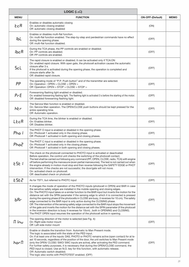
LOGIC (LOG)
MENU FUNCTION ON-OFF-(Default) MEMO
TCAEnables or disables automatic closingOn: automatic closing enabledOff: automatic closing disabled
(ON)
IBL
Enables or disables multi-flat function.On: multi-flat function enabled. The step-by-step and perdestrian commands have no effect during the opening phase.Off: multi-flat function disabled.
(OFF)
IBCADuring the TCA phase, the PP controls are enabled or disabled.On: PP controls are disabled.Off: PP controls are enabled.
(OFF)
SCL
The rapid closure is enabled or disabled. It can be activated only if TCA:ONOn: enabled rapid closure. With open gate, the photocell activation causes the automatic closure after 3 s. If the photocell is activated during the opening phase, the operation is completed and closure starts after 3s Off: disabled rapid closure.
(OFF)
PPThe operating mode of “P.P. Push button” and of the transmitter are selected.On: Operation : OPEN > CLOSE > OPEN >Off: Operation: OPEN > STOP > CLOSE > STOP >
(OFF)
PREForewarning flashing light enabled or disabled.On: enabled forewarning flashing light. The flashing light is activated 3 s before the starting of the motor.Off: disabled forewarning flashing light.
(OFF)
HTR
The Service Man function is enabled or disabled.On: Service Man operation. The OPEN/CLOSE push buttons should be kept pressed for the entire operating time.Off: Automatic operation.
(OFF)
LTCADuring the TCA time, the blinker is enabled or disabled.On: Enables blinker.Off: Disables blinker.
(OFF)
Pho1The PHOT O input is enabled or disabled in the opening phase.On: Photocell 1 activated only in the closing phase.Off: Photocell 1 activated in both opening and closing phases.
(OFF)
Pho2The PHOT C input is enabled or disabled in the opening phase.On: Photocell 1 activated only in the closing phase.Off: Photocell 1 activated in both opening and closing phases.
(OFF)
tst1
The check on the photocell connected to PHOTO input is activated or deactivatedBefore operation, the control unit checks the switching of the photocell contact. The test shall be carried out following any command (PP, OPEN, CLOSE, radio, TCA) with engine off before performing the manoeuvre (even partial manoeuvres). The test is not carried out when the engine already in motion must stop and then reverse following the SAFETY EDGE or PHOT intervention. If the checks are not successful, the door/gate will not move.On: activated check on photocell.Off: deactivated check on photocell.
(OFF)
tst2 As for TST1, but referred to PHOTC input (OFF)
bar
It changes the mode of operation of the PHOTO inputs (photocell in OPEN) and BAR in case the sensitive safety edges are installed in the mobile opening and closing edges.On: The PHOTO input takes on a similar function to the BAR input but inverts the motion for the distance set with the SPIN parameter if the sensing edge to which it is connected is pressed during the opening phase (if the photocells in CLOSE are busy, it reverses for 10 cm). The safety edge connected to the BAR input is only active during the CLOSING phase.Off: The intervention of the sensing safety edge connected to the BAR input stops the movement of the gate and inverts the motion for the distance set with the SPIN parameter (if the photocell in the inversion direction is busy it reverses for 10cm) , both in OPENING and CLOSING.The PHOT OPEN input resumes the operation of the photocell active in opening.
(OFF)
MINVThe opening direction of the motor is selected (see Fig. 4):On: Right side motor mount Off: Left side motor mount
(OFF)
horm
Enable or disable the transition from Automatic to Man Present mode.The logic is associated with the state of the PED input.On: If at least one of the inputs: DAS, PHOTO or PHOTC remains active (open contact) for at le-ast 10 seconds, regardless of the position of the door, the unit switches to Man Present mode (only the OPEN/ CLOSE/ SWO/ SWC inputs are active), after activating the PED command.For further safety purposes, it is necessary that during the OPEN/CLOSE command, the PED input is closed. Use an N.O. key for this function, with automatic release.Off: Automatic switch disabled.The logic also works with PHOTOTEST enabled. (OFF)
(OFF)
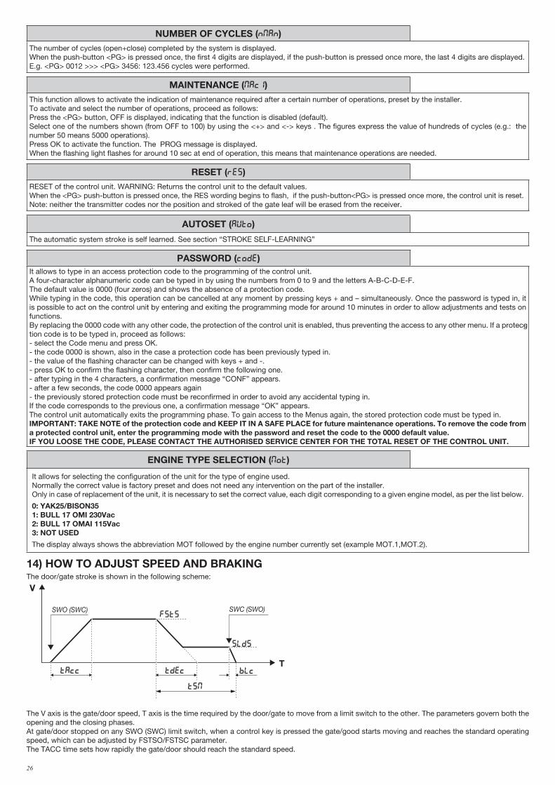
26
NUMBER OF CYCLES (Nman)The number of cycles (open+close) completed by the system is displayed.When the push-button <PG> is pressed once, the first 4 digits are displayed, if the push-button is pressed once more, the last 4 digits are displayed.E.g. <PG> 0012 >>> <PG> 3456: 123.456 cycles were performed.
MAINTENANCE (maci)This function allows to activate the indication of maintenance required after a certain number of operations, preset by the installer.To activate and select the number of operations, proceed as follows:Press the <PG> button, OFF is displayed, indicating that the function is disabled (default).Select one of the numbers shown (from OFF to 100) by using the <+> and <-> keys . The figures express the value of hundreds of cycles (e.g.: the number 50 means 5000 operations).Press OK to activate the function. The PROG message is displayed.When the flashing light flashes for around 10 sec at end of operation, this means that maintenance operations are needed.
RESET (RES)RESET of the control unit. WARNING: Returns the control unit to the default values.When the <PG> push-button is pressed once, the RES wording begins to flash, if the push-button<PG> is pressed once more, the control unit is reset.Note: neither the transmitter codes nor the position and stroked of the gate leaf will be erased from the receiver.
AUTOSET (AUTO)
The automatic system stroke is self learned. See section “STROKE SELF-LEARNING”
PASSWORD (CODE)It allows to type in an access protection code to the programming of the control unit.A four-character alphanumeric code can be typed in by using the numbers from 0 to 9 and the letters A-B-C-D-E-F.The default value is 0000 (four zeros) and shows the absence of a protection code.While typing in the code, this operation can be cancelled at any moment by pressing keys + and – simultaneously. Once the password is typed in, it is possible to act on the control unit by entering and exiting the programming mode for around 10 minutes in order to allow adjustments and tests on functions.By replacing the 0000 code with any other code, the protection of the control unit is enabled, thus preventing the access to any other menu. If a protecg-tion code is to be typed in, proceed as follows:- select the Code menu and press OK.- the code 0000 is shown, also in the case a protection code has been previously typed in.- the value of the flashing character can be changed with keys + and -.- press OK to confirm the flashing character, then confirm the following one. - after typing in the 4 characters, a confirmation message “CONF” appears.- after a few seconds, the code 0000 appears again- the previously stored protection code must be reconfirmed in order to avoid any accidental typing in.If the code corresponds to the previous one, a confirmation message “OK” appears.The control unit automatically exits the programming phase. To gain access to the Menus again, the stored protection code must be typed in.IMPORTANT: TAKE NOTE of the protection code and KEEP IT IN A SAFE PLACE for future maintenance operations. To remove the code from a protected control unit, enter the programming mode with the password and reset the code to the 0000 default value.IF YOU LOOSE THE CODE, PLEASE CONTACT THE AUTHORISED SERVICE CENTER FOR THE TOTAL RESET OF THE CONTROL UNIT.
ENGINE TYPE SELECTION (mot)
It allows for selecting the configuration of the unit for the type of engine used.Normally the correct value is factory preset and does not need any intervention on the part of the installer.Only in case of replacement of the unit, it is necessary to set the correct value, each digit corresponding to a given engine model, as per the list below.
0: YAK25/BISON351: BULL 17 OMI 230Vac2: BULL 17 OMAI 115Vac3: NOT USED
The display always shows the abbreviation MOT followed by the engine number currently set (example MOT.1,MOT.2).
14) HOW TO ADJUST SPEED AND BRAKINGThe door/gate stroke is shown in the following scheme:
V
T
FSTS
slds
BLcTAcc Tdec
TSM
SWO (SWC) SWC (SWO)
The V axis is the gate/door speed, T axis is the time required by the door/gate to move from a limit switch to the other. The parameters govern both the opening and the closing phases.At gate/door stopped on any SWO (SWC) limit switch, when a control key is pressed the gate/good starts moving and reaches the standard operating speed, which can be adjusted by FSTSO/FSTSC parameter. The TACC time sets how rapidly the gate/door should reach the standard speed.
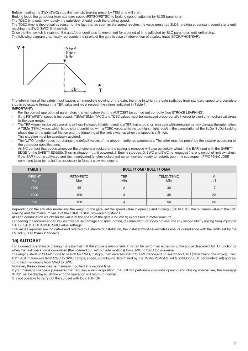
27
Before meeting the SWX (SWO) stop limit switch, braking preset by TSM time will start.Braking leads the gate/door from standard speed (FSTSO/FSTSC) to braking speed, adjusted by SLDS parameter.The TDEC time sets how rapidly the gate/door should reach the braking speed.The TDEC time is theoretical by reason of the fact that as soon as the speed reaches the value preset by SLDS, braking at constant speed starts until reaching the SWC (SWO) limit switch.Once the limit switch is reached, the gate/door continues its movement for a period of time adjusted by BLC parameter, until entire stop.The following diagram graphically represents the stroke of the gate in case of intervention of a safety input (STOP/PHOT/BAR):
V
T
FSTo/fstc
sldo/SldC
BLo/blcTAcc Tdec
TSMo/tsmc
SWO (SWC) SWC (SWO)
V
Ttbr
stopphotbar
The intervention of the safety input causes an immediate slowing of the gate, the time in which the gate switches from standard speed to a complete stop is adjustable through the TBR value and must respect the values indicated in Table 1.IMPORTANT:- For the correct operation of parameters it is mandatory that the AUTOSET be carried out correctly (see STROKE LEARNING).- If the FSTo(FSTc) speed is increased, TSMo(TSMc), TACC and TDEC values must be increased proportionally in order to avert any mechanical stress to the gear motor.- The TBR value must be set according to those indicated in table 1, setting a TBR that is too short on a gate with strong inertia may damage the automation. A TSMo (TSMc) value, which is too short, combined with a TDEC value, which is too high, might result in the cancellation of the SLDo (SLDc) braking phase due to the gate leaf friction and the triggering of the limit switches when the speed is still high. This situation must be absolutely avoided.- The AUTO function does not change the default values of the above-mentioned parameters. The latter must be preset by the installer according to the gate/door specifications.- An NC contact that opens whenever the engine is unlocked or the casing is removed will also be serially wired in the BAR input with the SAFETY EDGE (or the SAFETY EDGES). Thus, in situation 1. unit powered, 2. Engine stopped, 3. SWO and SWC not engaged (i.e. engine out of limit switches), if the BAR input is activated and then reactivated (engine locked and carter inserted, ready to restart), upon the subsequent PP/OPEN/CLOSE command (also by radio) it is necessary to force a slow manoeuvre.
TABLE 1 BULL 17 OMI / BULL 17 OMAI
WEIGHTKg
FSTO/FSTCMax
TBRMin
TSMO/TSMCMin
Vm/1'
1700 85 2 30 17
1000 100 3 35 20
500 120 4 50 24
Depending on the actuator model and the weight of the gate, set the speed value in opening and closing (FSTO/FSTC), the minimum value of the TBR braking and the minimum value of the TSMO/TSMC slowdown distance.At each combination we obtain the value of the speed of the gate (Column V) expressed in meters/minute.Exceeding the recommended values may cause damage and malfunction, the manufacturer does not assume any responsibility arising from improper FSTO/FSTC/TBR/TSMO/TSMC value settings.The values reported are indicative and referred to a standard installation, the installer must nevertheless ensure compliance with the limits set by the EN 12453, EN 12445 standards.
15) AUTOSETFor a correct operation of braking it is essential that the stroke is memorised. This can be performed either using the above described AUTO function or when the first operation is completed (then carried out without interruptions) from SWO to SWC (or viceversa).The engine starts in SLOW mode to search for SWO, it stops, then reverses still in SLOW manoeuvre to search for SWC (determining the stroke). Then first FAST manoeuvre from SWC to SWO (ramps, speed, slowdowns determined by the TSMo/TSMc/FSTo/FSTc/SLDo/SLDc parameters set) and se-cond fast manoeuvre from SWO to SWC.However, these values can be manually modified at a second time.If you manually change a parameter that requires a new acquisition, the unit will perform a complete opening and closing manoeuvre, the message "PRG” will be displayed. At the end the operation will return to normal.It is not possible to carry out the autoset with logic HTR:ON
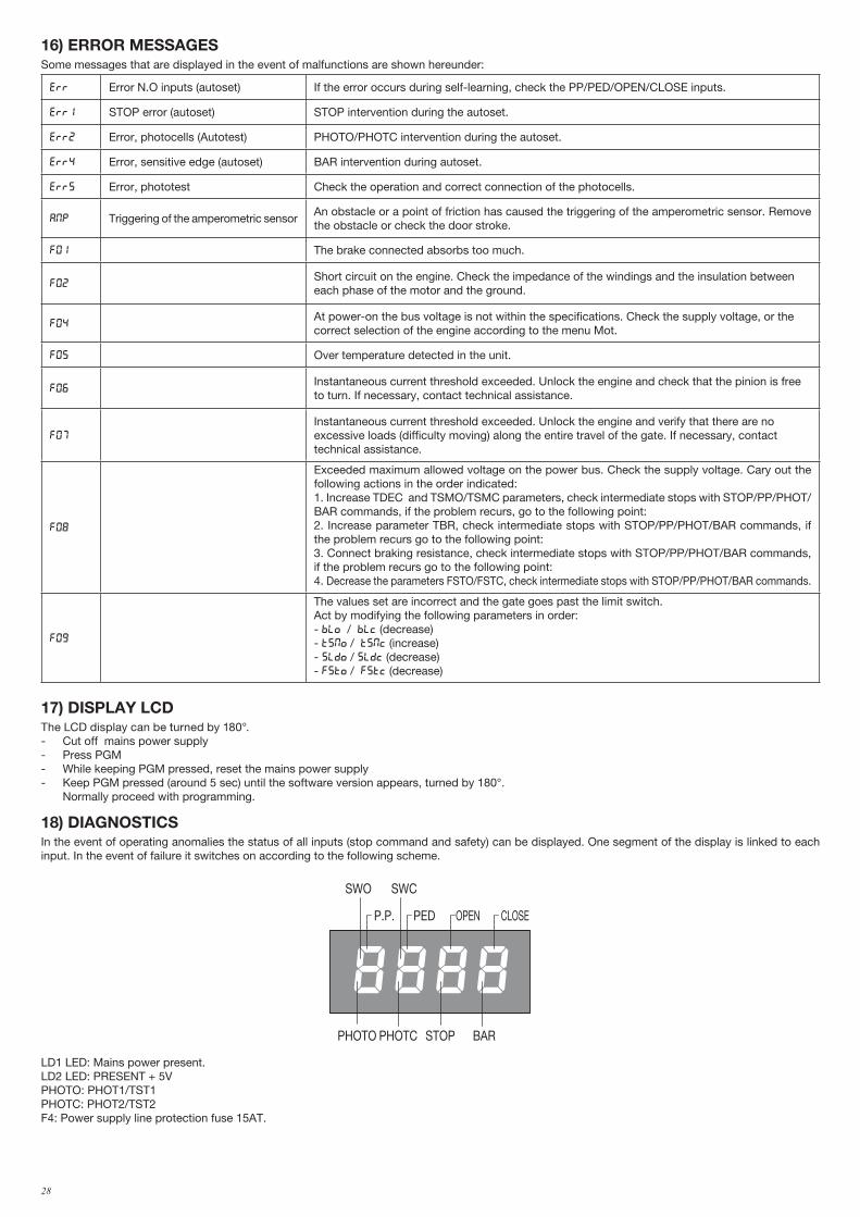
28
16) ERROR MESSAGESSome messages that are displayed in the event of malfunctions are shown hereunder:
err Error N.O inputs (autoset) If the error occurs during self-learning, check the PP/PED/OPEN/CLOSE inputs.
Err1 STOP error (autoset) STOP intervention during the autoset.
Err2 Error, photocells (Autotest) PHOTO/PHOTC intervention during the autoset.
Err4 Error, sensitive edge (autoset) BAR intervention during autoset.
Err5 Error, phototest Check the operation and correct connection of the photocells.
amp Triggering of the amperometric sensorAn obstacle or a point of friction has caused the triggering of the amperometric sensor. Remove the obstacle or check the door stroke.
F01 The brake connected absorbs too much.
F02Short circuit on the engine. Check the impedance of the windings and the insulation between each phase of the motor and the ground.
F04At power-on the bus voltage is not within the specifications. Check the supply voltage, or the correct selection of the engine according to the menu Mot.
F05 Over temperature detected in the unit.
F06Instantaneous current threshold exceeded. Unlock the engine and check that the pinion is free to turn. If necessary, contact technical assistance.
F07
Instantaneous current threshold exceeded. Unlock the engine and verify that there are no excessive loads (difficulty moving) along the entire travel of the gate. If necessary, contact technical assistance.
F08
Exceeded maximum allowed voltage on the power bus. Check the supply voltage. Cary out the following actions in the order indicated:1. Increase TDEC and TSMO/TSMC parameters, check intermediate stops with STOP/PP/PHOT/BAR commands, if the problem recurs, go to the following point:2. Increase parameter TBR, check intermediate stops with STOP/PP/PHOT/BAR commands, if the problem recurs go to the following point:3. Connect braking resistance, check intermediate stops with STOP/PP/PHOT/BAR commands, if the problem recurs go to the following point:4. Decrease the parameters FSTO/FSTC, check intermediate stops with STOP/PP/PHOT/BAR commands.
F09
The values set are incorrect and the gate goes past the limit switch.Act by modifying the following parameters in order:- blo / blc (decrease)- tsmo / tsmc (increase)- sldo / sldc (decrease)- fsto / fstc (decrease)
17) DISPLAY LCDThe LCD display can be turned by 180°.- Cut off mains power supply- Press PGM- While keeping PGM pressed, reset the mains power supply- Keep PGM pressed (around 5 sec) until the software version appears, turned by 180°. Normally proceed with programming.
18) DIAGNOSTICSIn the event of operating anomalies the status of all inputs (stop command and safety) can be displayed. One segment of the display is linked to each input. In the event of failure it switches on according to the following scheme.
PHOTO
SWC
STOP
SWO
PHOTC BAR
P.P. PED OPEN CLOSE
LD1 LED: Mains power present.LD2 LED: PRESENT + 5VPHOTO: PHOT1/TST1PHOTC: PHOT2/TST2F4: Power supply line protection fuse 15AT.
29
19) MAINTENANCEThe following table is used to record maintenance operations, improvement or repair works carried out by the expert engineer.
Date _ _ _ _ _ _ _ _ _ _ _ _ _ _ _ _ _ _ _ _ _ _ _ _ _ _ _ _ _ _ _ _ Engineer's Signature _ _ _ _ _ _ _ _ _ _ _ _ _ _ _ _ _ _ _ _ _ _ _ Stamp
Description of operation
_ _ _ _ _ _ _ _ _ _ _ _ _ _ _ _ _ _ _ _ _ _ _ _ _ _ _ _ _ _ _ _ _ _ _ _ _ _ _ _ _ _ _ _ _ _ _ _ _ _ _ _ _ _ _ _ _ _ _ _ _ _ _ _ _ _ _ _ _ _ _ _ _
_ _ _ _ _ _ _ _ _ _ _ _ _ _ _ _ _ _ _ _ _ _ _ _ _ _ _ _ _ _ _ _ _ _ _ _ _ _ _ _ _ _ _ _ _ _ _ _ _ _ _ _ _ _ _ _ _ _ _ _ _ _ _ _ _ _ _ _ _ _ _ _ _
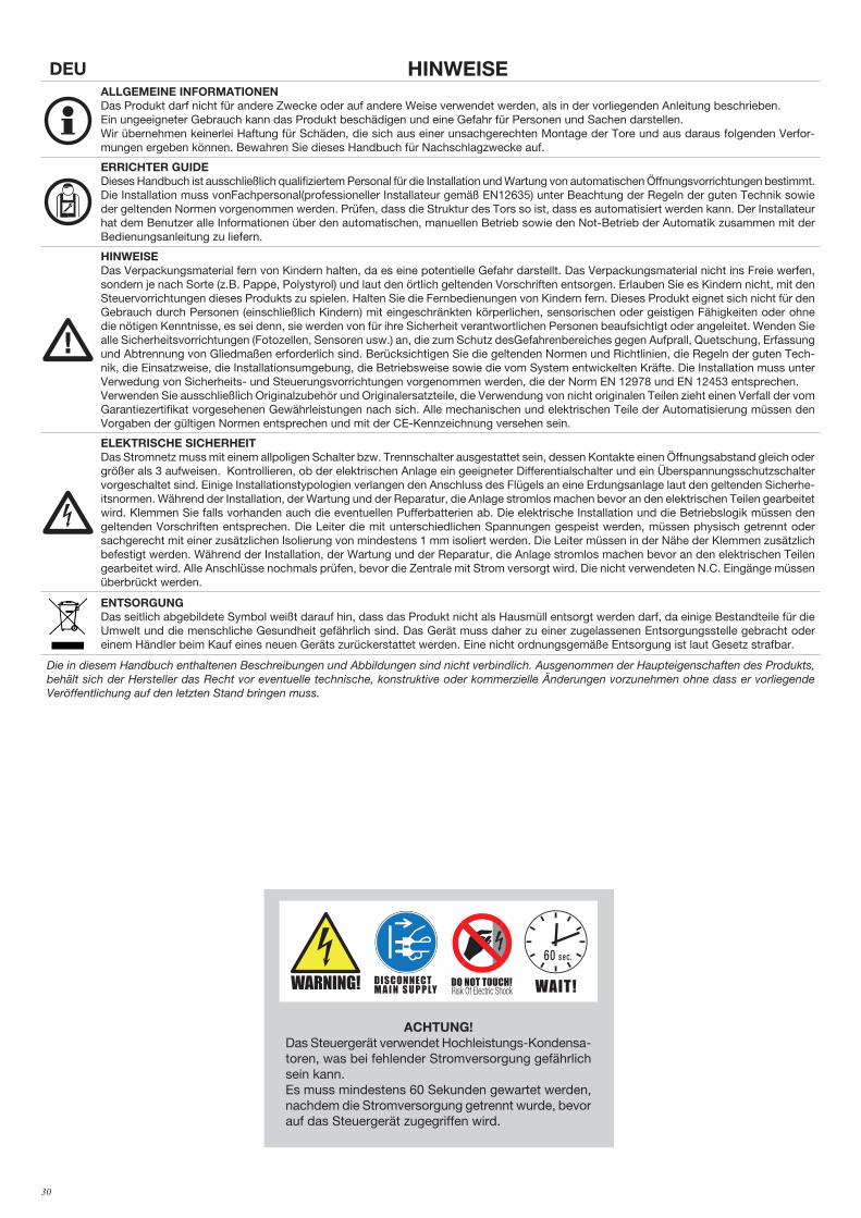
30
DEU HINWEISEALLGEMEINE INFORMATIONENDas Produkt darf nicht für andere Zwecke oder auf andere Weise verwendet werden, als in der vorliegenden Anleitung beschrieben. Ein ungeeigneter Gebrauch kann das Produkt beschädigen und eine Gefahr für Personen und Sachen darstellen.Wir übernehmen keinerlei Haftung für Schäden, die sich aus einer unsachgerechten Montage der Tore und aus daraus folgenden Verfor-mungen ergeben können. Bewahren Sie dieses Handbuch für Nachschlagzwecke auf.
ERRICHTER GUIDEDieses Handbuch ist ausschließlich qualifiziertem Personal für die Installation und Wartung von automatischen Öffnungsvorrichtungen bestimmt.Die Installation muss vonFachpersonal(professioneller Installateur gemäß EN12635) unter Beachtung der Regeln der guten Technik sowie der geltenden Normen vorgenommen werden. Prüfen, dass die Struktur des Tors so ist, dass es automatisiert werden kann. Der Installateur hat dem Benutzer alle Informationen über den automatischen, manuellen Betrieb sowie den Not-Betrieb der Automatik zusammen mit der Bedienungsanleitung zu liefern.
HINWEISEDas Verpackungsmaterial fern von Kindern halten, da es eine potentielle Gefahr darstellt. Das Verpackungsmaterial nicht ins Freie werfen, sondern je nach Sorte (z.B. Pappe, Polystyrol) und laut den örtlich geltenden Vorschriften entsorgen. Erlauben Sie es Kindern nicht, mit den Steuervorrichtungen dieses Produkts zu spielen. Halten Sie die Fernbedienungen von Kindern fern. Dieses Produkt eignet sich nicht für den Gebrauch durch Personen (einschließlich Kindern) mit eingeschränkten körperlichen, sensorischen oder geistigen Fähigkeiten oder ohne die nötigen Kenntnisse, es sei denn, sie werden von für ihre Sicherheit verantwortlichen Personen beaufsichtigt oder angeleitet. Wenden Sie alle Sicherheitsvorrichtungen (Fotozellen, Sensoren usw.) an, die zum Schutz desGefahrenbereiches gegen Aufprall, Quetschung, Erfassung und Abtrennung von Gliedmaßen erforderlich sind. Berücksichtigen Sie die geltenden Normen und Richtlinien, die Regeln der guten Tech-nik, die Einsatzweise, die Installationsumgebung, die Betriebsweise sowie die vom System entwickelten Kräfte. Die Installation muss unter Verwedung von Sicherheits- und Steuerungsvorrichtungen vorgenommen werden, die der Norm EN 12978 und EN 12453 entsprechen.Verwenden Sie ausschließlich Originalzubehör und Originalersatzteile, die Verwendung von nicht originalen Teilen zieht einen Verfall der vom Garantiezertifikat vorgesehenen Gewährleistungen nach sich. Alle mechanischen und elektrischen Teile der Automatisierung müssen den Vorgaben der gültigen Normen entsprechen und mit der CE-Kennzeichnung versehen sein.
ELEKTRISCHE SICHERHEITDas Stromnetz muss mit einem allpoligen Schalter bzw. Trennschalter ausgestattet sein, dessen Kontakte einen Öffnungsabstand gleich oder größer als 3 aufweisen. Kontrollieren, ob der elektrischen Anlage ein geeigneter Differentialschalter und ein Überspannungsschutzschalter vorgeschaltet sind. Einige Installationstypologien verlangen den Anschluss des Flügels an eine Erdungsanlage laut den geltenden Sicherhe-itsnormen. Während der Installation, der Wartung und der Reparatur, die Anlage stromlos machen bevor an den elektrischen Teilen gearbeitet wird. Klemmen Sie falls vorhanden auch die eventuellen Pufferbatterien ab. Die elektrische Installation und die Betriebslogik müssen den geltenden Vorschriften entsprechen. Die Leiter die mit unterschiedlichen Spannungen gespeist werden, müssen physisch getrennt oder sachgerecht mit einer zusätzlichen Isolierung von mindestens 1 mm isoliert werden. Die Leiter müssen in der Nähe der Klemmen zusätzlich befestigt werden. Während der Installation, der Wartung und der Reparatur, die Anlage stromlos machen bevor an den elektrischen Teilen gearbeitet wird. Alle Anschlüsse nochmals prüfen, bevor die Zentrale mit Strom versorgt wird. Die nicht verwendeten N.C. Eingänge müssen überbrückt werden.
ENTSORGUNGDas seitlich abgebildete Symbol weißt darauf hin, dass das Produkt nicht als Hausmüll entsorgt werden darf, da einige Bestandteile für die Umwelt und die menschliche Gesundheit gefährlich sind. Das Gerät muss daher zu einer zugelassenen Entsorgungsstelle gebracht oder einem Händler beim Kauf eines neuen Geräts zurückerstattet werden. Eine nicht ordnungsgemäße Entsorgung ist laut Gesetz strafbar.
Die in diesem Handbuch enthaltenen Beschreibungen und Abbildungen sind nicht verbindlich. Ausgenommen der Haupteigenschaften des Produkts, behält sich der Hersteller das Recht vor eventuelle technische, konstruktive oder kommerzielle Änderungen vorzunehmen ohne dass er vorliegende Veröffentlichung auf den letzten Stand bringen muss.
ACHTUNG!Das Steuergerät verwendet Hochleistungs-Kondensa-toren, was bei fehlender Stromversorgung gefährlich sein kann. Es muss mindestens 60 Sekunden gewartet werden, nachdem die Stromversorgung getrennt wurde, bevor auf das Steuergerät zugegriffen wird.
Read Instructions
DO NOT TOUCH!DISCONNECT M A I N S U P P LY WAIT!
60 sec.
WARNING!
F8369256
Etichetta WARNING: Formato 55x50mm
stampa su PVC adesivo4 colori
Read Instructions
DO NOT TOUCH!DISCONNECT M A I N S U P P LY WAIT!
60 sec.
WARNING!
F8369256
Etichetta WARNING: Formato 55x50mm
stampa su PVC adesivo4 colori
31
1) ALLGEMEINE EIGENSHAFTENAutomatik mit einphasiger Speisung für Schiebetore.
2) ALLGEMEINE INFORMATIONFür eine einwandfreie Funktion der Automation für Schiebegitter, muß das zu automatisierende Gitter folgende Eigenschaften haben:- Die Führungsschiene und die Räder müssen entsprechend dimensioniert und periodisch gewartet werden, um übermäßige Reibungen während dem
Gleiten des Gitters zu vermeiden.- Während des Betriebes darf das Gitter keine übermaßige Schwankungen aufweisen.- Der Offnungs- und Verschlußhub muß durch einen mechanischen Endanschlag begrenzt werden (nach geltender Sichereitsnormen).
3) TECHNISCHE DATEN
BULL 17 OMI BULL 17 OMAI
Speisung 230Vac 50/60Hz 115Vac 60Hz
Verbrauch 7 A 8 A
Kräftepaar 68 Nm 40 Nm
Inverter Ja Ja
Betriebsintermittenz 40% 40%
Schutzklasse IP44 IP44
Betriebstemperatur -20°C / +50°C -20°C / +50°C
Gittersgewicht max. 1700 kg 1700 kg
Modul der Zahnstange M4 Z 18* M4 Z 18*
Öffnungsgeschwindigkeit 24 m/min MAX 24 m/min MAX
Geräuschentwicklung <70 dB <70 dB
Schmierung Öl Öl
Gewicht 21,3 kg 21,3 kg
* M6 Z13 (art. RI.P6 - optional)
4) VERLEGUNG DER FUNDAMENTPLATTEIn der Abbildung 2 sind die Maße der Fundamentplatte angegeben.Wichtig ist dabei den Abstand von der Zahnstange einzuhalten, um den Aktuator positionieren und abnehmen zu können nachdem die Zahnstange des Flügels befestigt worden ist.Grundsätzlich kann die Fundamentplatte folgendermaßen befestigt werden:
1 Verlegung ohne Höheneinstellung auf vorhandenem Betonuntergrund (Abb. 2) Indem die Platte als Schablone verwendet wird, werden 4 Löcher mit einem Durchmesser von 10 mm geboren, in die Stahldübel mit Gewinde Ø10x120mm ähnlich wie in Abb. 2 eingesetzt werden.Den Aktuator direkt am Boden gemäß Abb. 7 blockieren.
1) ALLGEMEINE EIGENSHAFTEN ....................................................................31
2) ALLGEMEINE INFORMATION ......................................................................31
3) TECHNISCHE DATEN..................................................................................31
4) VERLEGUNG DER FUNDAMENTPLATTE ......................................................31
5) BEFESTIGUNG DER ZAHNSTANGE..............................................................32
6) POSITIONIERUNG DER ENDANSCHLAGBÜGELN (BILD 10) ..........................32
7) INSTALLATION DER MAGNETEN(BULL 17 OMI.S/BULL 17 OMAI.S) ABB.11 32
8) MANUELLE BETÄTIGUNG (BILD 12-13-14) .................................................32
9) ELEKTRISCHE ANSCHLÜSSE ......................................................................32
10) STEUEREINHEIT CP.YAK OTI .....................................................................32
10.1) FUNKTIONEN DER EIN-/AUSGÄNGE ................................................ 32
10.2) ANSCHLÜSSE ÜBERPRÜFEN .......................................................... 33
11) PROGRAMMIERUNG ................................................................................33
12) FÜR DEN ZUGRIFF AUF DIE PROGRAMMIERUNG: .....................................33
12.1) SELBSTLERNFUNKTION FÜR MASSE UND EICHUNG DER QUETSC .. 33
13) PARAMETER, LOGIKEN UND SONDERFUNKTIONEN ..................................33
14) EINSTELLUNG DER GESCHWINDIGKEIT UND DER GESCHWINDIGKEITSAB 36
15) AUTOSET ................................................................................................37
16) FEHLERMELDUNGEN ...............................................................................37
17) LCD DISPLAY ..........................................................................................38
18) DIAGNOSE ..............................................................................................38
19) WARTUNG ...............................................................................................39
INHALT
SCHNELLPROGRAMMIERUNG- Legen Sie die Motorposition über das Menü MINV, standardmäßig wird die Automatisierung als Links MOTOR festgelegt ist.
- Rufen Sie das Menü AUTO, bestätigen Sie 2 Mal mit <PG>und warten Sie, bis die Automatisierung der Autoset Parameter durchgeführt hat.
- In den Menüs PAR und LOG die Betriebsparameter und -logiken auswählen, die im Hinblick auf die Art der Installierung nötig sind.
WICHTIG: Die Schranke führt nach jeder Parameteränderung FSTS. SLDO, SLDC, TSMO, TSMC eine komplette Öffnung und Schließung durch, um die neuen Strom- und Drehmomentwerte zu erfassen. Auf dem Display erscheint die Meldung „PRG“.- Schließen Sie zum Speichern der Sender drücken Sie die Taste des Empfängers.
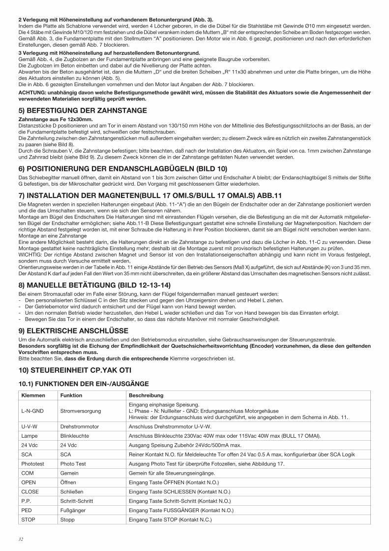
32
2 Verlegung mit Höheneinstellung auf vorhandenem Betonuntergrund (Abb. 3). Indem die Platte als Schablone verwendet wird, werden 4 Löcher geboren, in die die Dübel für die Stahlstäbe mit Gewinde Ø10 mm eingesetzt werden.Die 4 Stäbe mit Gewinde M10/120 mm festziehen und die Dübel verankern indem die Muttern „B“ mit der entsprechenden Scheibe am Boden festgezogen werden.Gemäß Abb. 3, die Fundamentplatte mit den Stellmuttern “A” positionieren. Den Motor wie in Abb. 6 gezeigt, positionieren und nach den erforderlichen Einstellungen, diesen gemäß Abb. 7 blockieren.
3 Verlegung mit Höheneinstellung auf herzustellendem Betonuntergrund. Gemäß Abb. 4, die Zugbolzen an der Fundamentplatte anbringen und eine geeignete Baugrube vorbereiten.Die Zugbolzen im Beton einbetten und dabei auf die Nivellierung der Platte achten. Abwarten bis der Beton ausgehärtet ist, dann die Muttern „D“ und die breiten Scheiben „R“ 11x30 abnehmen und unter die Platte bringen, um die Höhe des Aktuators einstellen zu können (Abb. 5).Die in Abb. 6 gezeigten Einstellungen vornehmen und den Motor laut Angaben der Abb. 7 blockieren.
ACHTUNG: unabhängig davon welche Befestigungsmethode gewählt wird, müssen die Stabilität des Aktuators sowie die Angemessenheit der verwendeten Materialien sorgfältig geprüft werden.
5) BEFESTIGUNG DER ZAHNSTANGEZahnstange aus Fe 12x30mm.Distanzstücke D positionieren und am Tor in einem Abstand von 130/150 mm Höhe von der Mittellinie des Befestigungsschlitzlochs an der Basis, an der die Fundamentplatte befestigt wird, schweißen oder festschrauben.Die Zahnteilung zwischen den Zahnstangenstücken muß außerdem eingehalten werden; zu diesem Zweck wäre es nützlich ein zweites Zahnstangenstück zu paaren (siehe Bild 8).Durch die Schrauben V, die Zahnstange befestigen; bitte beachten, daß nach der Installation des Aktuators, ein Spiel von ca. 1mm zwischen Zahnstange und Zahnrad bleibt (siehe Bild 9). Zu diesem Zweck können die in der Zahnstange gefrästen Nuten verwendet werden.
6) POSITIONIERUNG DER ENDANSCHLAGBÜGELN (BILD 10)Das Schiebegitter manuell öffnen, damit ein Abstand von 1 bis 3cm zwischen Gitter und Endschalter A bleibt; der Endanschlagtbügel S mittels der Stifte G befestigen, bis der Mikroschalter gedrückt wird. Den Vorgang mit geschlossenem Gitter wiederholen.
7) INSTALLATION DER MAGNETEN(BULL 17 OMI.S/BULL 17 OMAI.S) ABB.11Die Magneten werden in speziellen Halterungen eingebaut (Abb. 11-“A”) die an den Bügeln der Endschalter oder an der Zahnstange positioniert werden und die das Umschalten steuern, wenn sie sich den Sensoren nähern.Montage am Bügel des Endschalters Die Halterungen sind mit einrastenden Flügeln versehen, die die Befestigung an die mit der Automatik mitgeliefer-ten Bügel der Endschalter ermöglichen; siehe Abb.11-B Diese Befestigungsart gestattet eine schnelle Einstellung der Magnetenposition. Nachdem der richtige Abstand festgelegt worden ist, mit einer Schraube die Halterung in ihrer Position blockieren, damit sie am Bügel nicht verschoben werden kann.Montage an eine Zahnstange Eine andere Möglichkeit besteht darin, die Halterungen direkt an die Zahnstange zu befestigen und dazu die Löcher in Abb. 11-C zu verwenden. Diese Montage gestattet keine nachträgliche Einstellung mehr; deshalb ist die Montage zuerst mit provisorisch befestigten Halterungen zu prüfen.WICHTIG: Der richtige Abstand zwischen Magnet und Sensor ist von den Installationseigenschaften abhängig und kann nicht im Voraus festgelegt, sondern muss durch Versuche ermittelt werden,Orientierungsweise werden in der Tabelle in Abb. 11 einige Abstände für den Betrieb des Sensors (Maß X) aufgeführt, die sich auf Abstände (K) von 3 und 35 mm.Der Abstand K darf auf jeden Fall den Wert von 35 mm nicht überschreiten, da ein größerer Abstand das Umschalten des magnetischen Sensors nicht zulässt.
8) MANUELLE BETÄTIGUNG (BILD 12-13-14)Bei einem Stromausfall oder im Falle einer Störung, kann der Flügel folgendermaßen manuell gesteuert werden:- Den personalisierten Schlüssel C in den Sitz stecken und gegen den Uhrzeigersinn drehen und Hebel L ziehen.- Der Getriebemotor wird dadurch entsichert und der Flügel kann von Hand bewegt werden.- Um den normalen Betrieb wieder herzustellen, den Hebel L wieder schließen und das Tor von Hand bewegen bis das Einrasten erfolgt.- Bewegen Sie das Tor in einem der Endschalter, so dass das nächste Manöver mit normaler Geschwindigkeit.
9) ELEKTRISCHE ANSCHLÜSSEUm die Automatik elektrisch anzuschließen und den Betriebsmodus einzustellen, siehe Gebrauchsanweisungen der Steuerungszentrale.Besonders sorgfältig ist die Eichung der Empfindlichkeit der Quetschsicherheitsvorrichtung (Encoder) vorzunehmen, da diese den geltenden Vorschriften entsprechen muss.Bitte beachten Sie, dass die Erdung durch die entsprechende Klemme vorgeschrieben ist.
10) STEUEREINHEIT CP.YAK OTI
10.1) FUNKTIONEN DER EIN-/AUSGÄNGE
Klemmen Funktion Beschreibung
L-N-GND StromversorgungEingang einphasige Speisung.L: Phase - N: Nullleiter - GND: Erdungsanschluss MotorgehäuseHinweis: der Erdungsanschluss wird durchgeführt, wie angegeben in dem Schema in Abb. 11.
U-V-W Drehstrommotor Anschluss Drehstrommotor U-V-W.
Lampe Blinkleuchte Anschluss Blinkleuchte 230Vac 40W max oder 115Vac 40W max (BULL 17 OMAI).
24 Vdc 24 Vdc Ausgang Speisung Zubehör 24Vdc/500mA max.
SCA SCA Reiner Kontakt N.O. für Meldeleuchte Tor offen 24 Vac 0.5 A max, konfigurierbar über SCA Logik
Phototest Photo Test Ausgang Photo Test für überprüfte Fotozellen, siehe Abbildung 17.
COM Gemein Gemein für alle Steuerungseingänge.
OPEN Öffnen Eingang Taste ÖFFNEN (Kontakt N.O.)
CLOSE Schließen Eingang Taste SCHLIESSEN (Kontakt N.O.)
P.P. Schritt-Schritt Eingang Taste Schritt-Schritt (Kontakt N.O.)
PED Fußgänger Eingang Taste FUSSGÄNGER (Kontakt N.O.)
STOP Stopp Eingang Taste STOP (Kontakt N.C.)
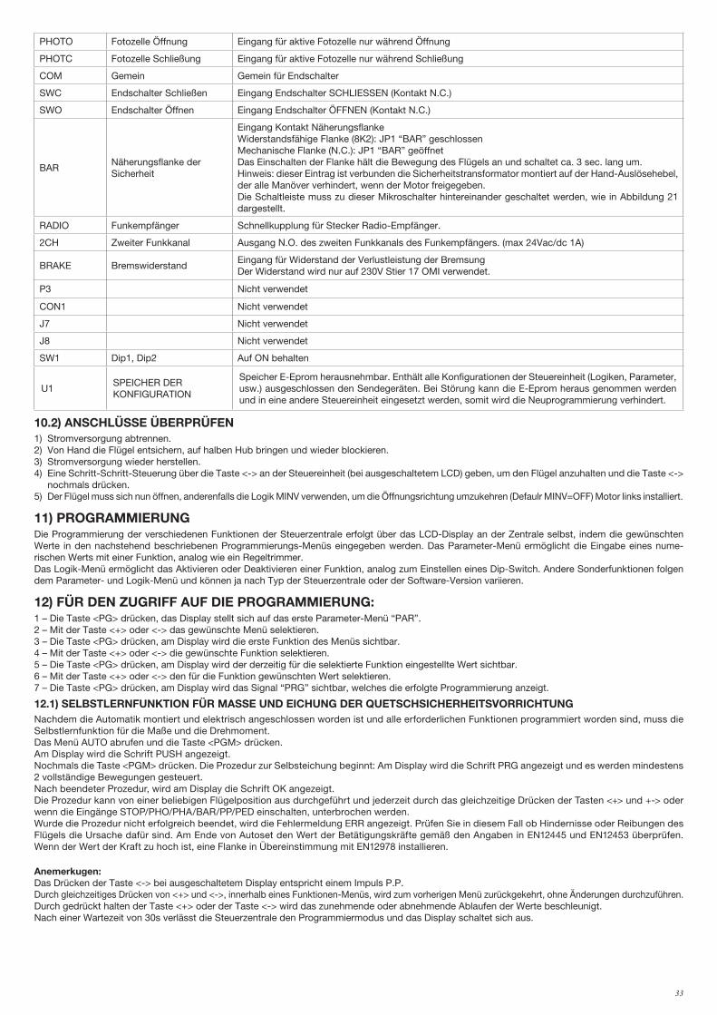
33
PHOTO Fotozelle Öffnung Eingang für aktive Fotozelle nur während Öffnung
PHOTC Fotozelle Schließung Eingang für aktive Fotozelle nur während Schließung
COM Gemein Gemein für Endschalter
SWC Endschalter Schließen Eingang Endschalter SCHLIESSEN (Kontakt N.C.)
SWO Endschalter Öffnen Eingang Endschalter ÖFFNEN (Kontakt N.C.)
BARNäherungsflanke derSicherheit
Eingang Kontakt NäherungsflankeWiderstandsfähige Flanke (8K2): JP1 “BAR” geschlossenMechanische Flanke (N.C.): JP1 “BAR” geöffnetDas Einschalten der Flanke hält die Bewegung des Flügels an und schaltet ca. 3 sec. lang um.Hinweis: dieser Eintrag ist verbunden die Sicherheitstransformator montiert auf der Hand-Auslösehebel, der alle Manöver verhindert, wenn der Motor freigegeben.Die Schaltleiste muss zu dieser Mikroschalter hintereinander geschaltet werden, wie in Abbildung 21 dargestellt.
RADIO Funkempfänger Schnellkupplung für Stecker Radio-Empfänger.
2CH Zweiter Funkkanal Ausgang N.O. des zweiten Funkkanals des Funkempfängers. (max 24Vac/dc 1A)
BRAKE BremswiderstandEingang für Widerstand der Verlustleistung der BremsungDer Widerstand wird nur auf 230V Stier 17 OMI verwendet.
P3 Nicht verwendet
CON1 Nicht verwendet
J7 Nicht verwendet
J8 Nicht verwendet
SW1 Dip1, Dip2 Auf ON behalten
U1SPEICHER DER KONFIGURATION
Speicher E-Eprom herausnehmbar. Enthält alle Konfigurationen der Steuereinheit (Logiken, Parameter, usw.) ausgeschlossen den Sendegeräten. Bei Störung kann die E-Eprom heraus genommen werden und in eine andere Steuereinheit eingesetzt werden, somit wird die Neuprogrammierung verhindert.
10.2) ANSCHLÜSSE ÜBERPRÜFEN1) Stromversorgung abtrennen.2) Von Hand die Flügel entsichern, auf halben Hub bringen und wieder blockieren.3) Stromversorgung wieder herstellen.4) Eine Schritt-Schritt-Steuerung über die Taste <-> an der Steuereinheit (bei ausgeschaltetem LCD) geben, um den Flügel anzuhalten und die Taste <->
nochmals drücken.5) Der Flügel muss sich nun öffnen, anderenfalls die Logik MINV verwenden, um die Öffnungsrichtung umzukehren (Defaulr MINV=OFF) Motor links installiert.
11) PROGRAMMIERUNGDie Programmierung der verschiedenen Funktionen der Steuerzentrale erfolgt über das LCD-Display an der Zentrale selbst, indem die gewünschten Werte in den nachstehend beschriebenen Programmierungs-Menüs eingegeben werden. Das Parameter-Menü ermöglicht die Eingabe eines nume-rischen Werts mit einer Funktion, analog wie ein Regeltrimmer.Das Logik-Menü ermöglicht das Aktivieren oder Deaktivieren einer Funktion, analog zum Einstellen eines Dip-Switch. Andere Sonderfunktionen folgen dem Parameter- und Logik-Menü und können ja nach Typ der Steuerzentrale oder der Software-Version variieren.
12) FÜR DEN ZUGRIFF AUF DIE PROGRAMMIERUNG:1 – Die Taste <PG> drücken, das Display stellt sich auf das erste Parameter-Menü “PAR”. 2 – Mit der Taste <+> oder <-> das gewünschte Menü selektieren.3 – Die Taste <PG> drücken, am Display wird die erste Funktion des Menüs sichtbar.4 – Mit der Taste <+> oder <-> die gewünschte Funktion selektieren.5 – Die Taste <PG> drücken, am Display wird der derzeitig für die selektierte Funktion eingestellte Wert sichtbar.6 – Mit der Taste <+> oder <-> den für die Funktion gewünschten Wert selektieren.7 – Die Taste <PG> drücken, am Display wird das Signal “PRG” sichtbar, welches die erfolgte Programmierung anzeigt.
12.1) SELBSTLERNFUNKTION FÜR MASSE UND EICHUNG DER QUETSCHSICHERHEITSVORRICHTUNGNachdem die Automatik montiert und elektrisch angeschlossen worden ist und alle erforderlichen Funktionen programmiert worden sind, muss die Selbstlernfunktion für die Maße und die Drehmoment.Das Menü AUTO abrufen und die Taste <PGM> drücken.Am Display wird die Schrift PUSH angezeigt.Nochmals die Taste <PGM> drücken. Die Prozedur zur Selbsteichung beginnt: Am Display wird die Schrift PRG angezeigt und es werden mindestens 2 vollständige Bewegungen gesteuert. Nach beendeter Prozedur, wird am Display die Schrift OK angezeigt.Die Prozedur kann von einer beliebigen Flügelposition aus durchgeführt und jederzeit durch das gleichzeitige Drücken der Tasten <+> und +-> oder wenn die Eingänge STOP/PHO/PHA/BAR/PP/PED einschalten, unterbrochen werden.Wurde die Prozedur nicht erfolgreich beendet, wird die Fehlermeldung ERR angezeigt. Prüfen Sie in diesem Fall ob Hindernisse oder Reibungen des Flügels die Ursache dafür sind. Am Ende von Autoset den Wert der Betätigungskräfte gemäß den Angaben in EN12445 und EN12453 überprüfen. Wenn der Wert der Kraft zu hoch ist, eine Flanke in Übereinstimmung mit EN12978 installieren.
Anemerkugen:Das Drücken der Taste <-> bei ausgeschaltetem Display entspricht einem Impuls P.P.Durch gleichzeitiges Drücken von <+> und <->, innerhalb eines Funktionen-Menüs, wird zum vorherigen Menü zurückgekehrt, ohne Änderungen durchzuführen.Durch gedrückt halten der Taste <+> oder der Taste <-> wird das zunehmende oder abnehmende Ablaufen der Werte beschleunigt.Nach einer Wartezeit von 30s verlässt die Steuerzentrale den Programmiermodus und das Display schaltet sich aus.
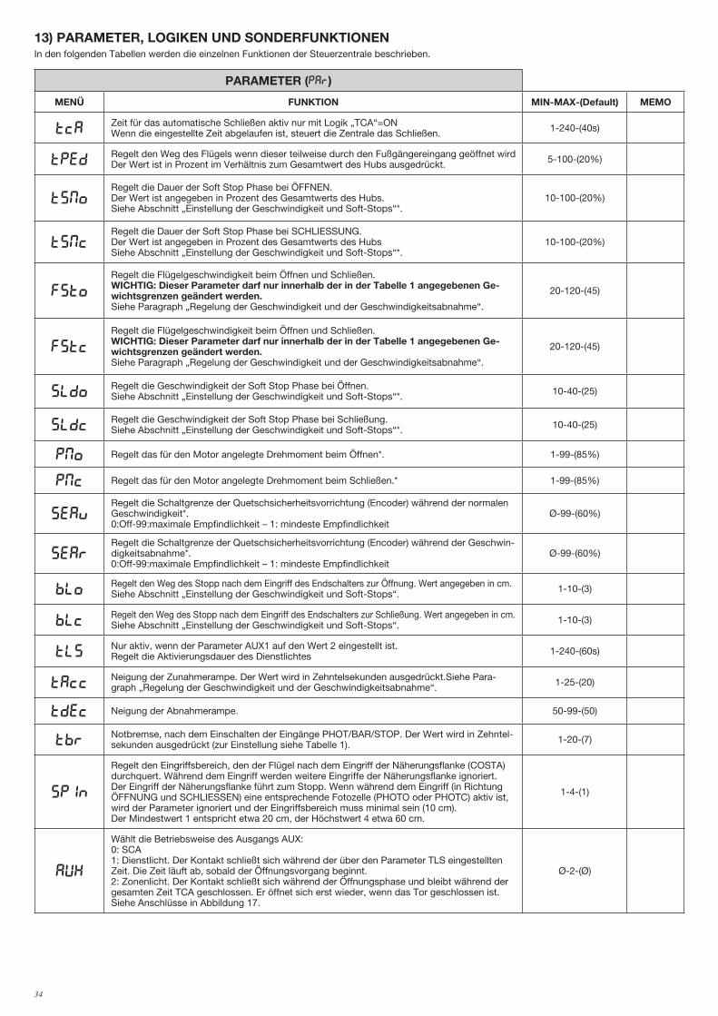
34
13) PARAMETER, LOGIKEN UND SONDERFUNKTIONENIn den folgenden Tabellen werden die einzelnen Funktionen der Steuerzentrale beschrieben.
PARAMETER (PAR)
MENÜ FUNKTION MIN-MAX-(Default) MEMO
TCAZeit für das automatische Schließen aktiv nur mit Logik „TCA“=ONWenn die eingestellte Zeit abgelaufen ist, steuert die Zentrale das Schließen. 1-240-(40s)
TpedRegelt den Weg des Flügels wenn dieser teilweise durch den Fußgängereingang geöffnet wird Der Wert ist in Prozent im Verhältnis zum Gesamtwert des Hubs ausgedrückt. 5-100-(20%)
tsmoRegelt die Dauer der Soft Stop Phase bei ÖFFNEN. Der Wert ist angegeben in Prozent des Gesamtwerts des Hubs.Siehe Abschnitt „Einstellung der Geschwindigkeit und Soft-Stops“*.
10-100-(20%)
TsMcRegelt die Dauer der Soft Stop Phase bei SCHLIESSUNG.Der Wert ist angegeben in Prozent des Gesamtwerts des HubsSiehe Abschnitt „Einstellung der Geschwindigkeit und Soft-Stops“*.
10-100-(20%)
FSToRegelt die Flügelgeschwindigkeit beim Öffnen und Schließen.WICHTIG: Dieser Parameter darf nur innerhalb der in der Tabelle 1 angegebenen Ge-wichtsgrenzen geändert werden.Siehe Paragraph „Regelung der Geschwindigkeit und der Geschwindigkeitsabnahme“.
20-120-(45)
fstcRegelt die Flügelgeschwindigkeit beim Öffnen und Schließen.WICHTIG: Dieser Parameter darf nur innerhalb der in der Tabelle 1 angegebenen Ge-wichtsgrenzen geändert werden.Siehe Paragraph „Regelung der Geschwindigkeit und der Geschwindigkeitsabnahme“.
20-120-(45)
sldoRegelt die Geschwindigkeit der Soft Stop Phase bei Öffnen.Siehe Abschnitt „Einstellung der Geschwindigkeit und Soft-Stops“*. 10-40-(25)
sldcRegelt die Geschwindigkeit der Soft Stop Phase bei Schließung.Siehe Abschnitt „Einstellung der Geschwindigkeit und Soft-Stops“*. 10-40-(25)
PMO Regelt das für den Motor angelegte Drehmoment beim Öffnen*. 1-99-(85%)
PMC Regelt das für den Motor angelegte Drehmoment beim Schließen.* 1-99-(85%)
sEavRegelt die Schaltgrenze der Quetschsicherheitsvorrichtung (Encoder) während der normalen Geschwindigkeit*.0:Off-99:maximale Empfindlichkeit – 1: mindeste Empfindlichkeit
Ø-99-(60%)
sEarRegelt die Schaltgrenze der Quetschsicherheitsvorrichtung (Encoder) während der Geschwin-digkeitsabnahme*.0:Off-99:maximale Empfindlichkeit – 1: mindeste Empfindlichkeit
Ø-99-(60%)
bloRegelt den Weg des Stopp nach dem Eingriff des Endschalters zur Öffnung. Wert angegeben in cm. Siehe Abschnitt „Einstellung der Geschwindigkeit und Soft-Stops“. 1-10-(3)
blcRegelt den Weg des Stopp nach dem Eingriff des Endschalters zur Schließung. Wert angegeben in cm. Siehe Abschnitt „Einstellung der Geschwindigkeit und Soft-Stops“. 1-10-(3)
TLSNur aktiv, wenn der Parameter AUX1 auf den Wert 2 eingestellt ist. Regelt die Aktivierungsdauer des Dienstlichtes 1-240-(60s)
TACCNeigung der Zunahmerampe. Der Wert wird in Zehntelsekunden ausgedrückt.Siehe Para-graph „Regelung der Geschwindigkeit und der Geschwindigkeitsabnahme“. 1-25-(20)
TDEC Neigung der Abnahmerampe. 50-99-(50)
TbrNotbremse, nach dem Einschalten der Eingänge PHOT/BAR/STOP. Der Wert wird in Zehntel-sekunden ausgedrückt (zur Einstellung siehe Tabelle 1). 1-20-(7)
spin
Regelt den Eingriffsbereich, den der Flügel nach dem Eingriff der Näherungsflanke (COSTA) durchquert. Während dem Eingriff werden weitere Eingriffe der Näherungsflanke ignoriert. Der Eingriff der Näherungsflanke führt zum Stopp. Wenn während dem Eingriff (in Richtung ÖFFNUNG und SCHLIESSEN) eine entsprechende Fotozelle (PHOTO oder PHOTC) aktiv ist, wird der Parameter ignoriert und der Eingriffsbereich muss minimal sein (10 cm).Der Mindestwert 1 entspricht etwa 20 cm, der Höchstwert 4 etwa 60 cm.
1-4-(1)
AUX
Wählt die Betriebsweise des Ausgangs AUX:0: SCA1: Dienstlicht. Der Kontakt schließt sich während der über den Parameter TLS eingestellten Zeit. Die Zeit läuft ab, sobald der Öffnungsvorgang beginnt.2: Zonenlicht. Der Kontakt schließt sich während der Öffnungsphase und bleibt während der gesamten Zeit TCA geschlossen. Er öffnet sich erst wieder, wenn das Tor geschlossen ist.Siehe Anschlüsse in Abbildung 17.
Ø-2-(Ø)
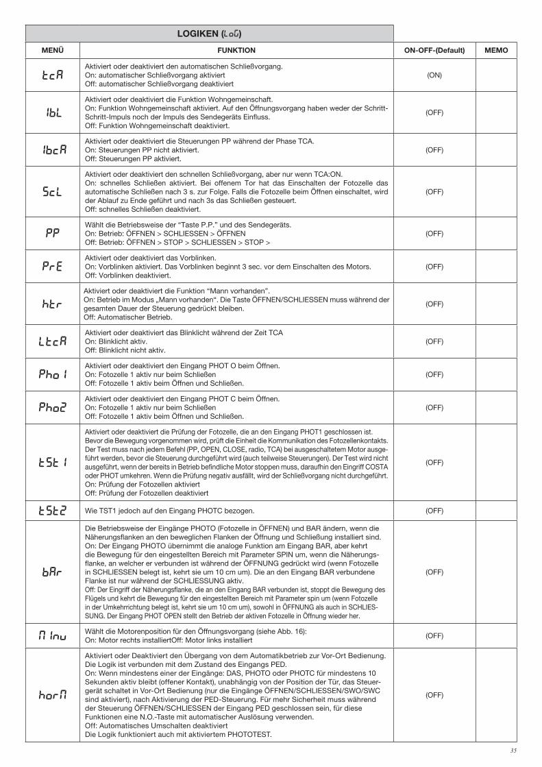
35
LOGIKEN (LOG)
MENÜ FUNKTION ON-OFF-(Default) MEMO
TCAAktiviert oder deaktiviert den automatischen Schließvorgang.On: automatischer Schließvorgang aktiviertOff: automatischer Schließvorgang deaktiviert
(ON)
IBL
Aktiviert oder deaktiviert die Funktion Wohngemeinschaft.On: Funktion Wohngemeinschaft aktiviert. Auf den Öffnungsvorgang haben weder der Schritt-Schritt-Impuls noch der Impuls des Sendegeräts Einfluss.Off: Funktion Wohngemeinschaft deaktiviert.
(OFF)
IBCAAktiviert oder deaktiviert die Steuerungen PP während der Phase TCA.On: Steuerungen PP nicht aktiviert.Off: Steuerungen PP aktiviert.
(OFF)
SCL
Aktiviert oder deaktiviert den schnellen Schließvorgang, aber nur wenn TCA:ON.On: schnelles Schließen aktiviert. Bei offenem Tor hat das Einschalten der Fotozelle das automatische Schließen nach 3 s. zur Folge. Falls die Fotozelle beim Öffnen einschaltet, wird der Ablauf zu Ende geführt und nach 3s das Schließen gesteuert.Off: schnelles Schließen deaktiviert.
(OFF)
PPWählt die Betriebsweise der “Taste P.P.” und des Sendegeräts.On: Betrieb: ÖFFNEN > SCHLIESSEN > ÖFFNENOff: Betrieb: ÖFFNEN > STOP > SCHLIESSEN > STOP >
(OFF)
PREAktiviert oder deaktiviert das Vorblinken.On: Vorblinken aktiviert. Das Vorblinken beginnt 3 sec. vor dem Einschalten des Motors.Off: Vorblinken deaktiviert.
(OFF)
HTR
Aktiviert oder deaktiviert die Funktion “Mann vorhanden”. On: Betrieb im Modus „Mann vorhanden“. Die Taste ÖFFNEN/SCHLIESSEN muss während der gesamten Dauer der Steuerung gedrückt bleiben.Off: Automatischer Betrieb.
(OFF)
LTCAAktiviert oder deaktiviert das Blinklicht während der Zeit TCAOn: Blinklicht aktiv.Off: Blinklicht nicht aktiv.
(OFF)
Pho1Aktiviert oder deaktiviert den Eingang PHOT O beim Öffnen.On: Fotozelle 1 aktiv nur beim SchließenOff: Fotozelle 1 aktiv beim Öffnen und Schließen.
(OFF)
Pho2Aktiviert oder deaktiviert den Eingang PHOT C beim Öffnen.On: Fotozelle 1 aktiv nur beim SchließenOff: Fotozelle 1 aktiv beim Öffnen und Schließen.
(OFF)
tst1
Aktiviert oder deaktiviert die Prüfung der Fotozelle, die an den Eingang PHOT1 geschlossen ist.Bevor die Bewegung vorgenommen wird, prüft die Einheit die Kommunikation des Fotozellenkontakts. Der Test muss nach jedem Befehl (PP, OPEN, CLOSE, radio, TCA) bei ausgeschaltetem Motor ausge-führt werden, bevor die Steuerung durchgeführt wird (auch teilweise Steuerungen). Der Test wird nicht ausgeführt, wenn der bereits in Betrieb befindliche Motor stoppen muss, daraufhin den Eingriff COSTA oder PHOT umkehren. Wenn die Prüfung negativ ausfällt, wird der Schließvorgang nicht durchgeführt.On: Prüfung der Fotozellen aktiviertOff: Prüfung der Fotozellen deaktiviert
(OFF)
tst2 Wie TST1 jedoch auf den Eingang PHOTC bezogen. (OFF)
bar
Die Betriebsweise der Eingänge PHOTO (Fotozelle in ÖFFNEN) und BAR ändern, wenn die Näherungsflanken an den beweglichen Flanken der Öffnung und Schließung installiert sind.On: Der Eingang PHOTO übernimmt die analoge Funktion am Eingang BAR, aber kehrt die Bewegung für den eingestellten Bereich mit Parameter SPIN um, wenn die Näherungs-flanke, an welcher er verbunden ist während der ÖFFNUNG gedrückt wird (wenn Fotozelle in SCHLIESSEN belegt ist, kehrt sie um 10 cm um). Die an den Eingang BAR verbundene Flanke ist nur während der SCHLIESSUNG aktiv.Off: Der Eingriff der Näherungsflanke, die an den Eingang BAR verbunden ist, stoppt die Bewegung des Flügels und kehrt die Bewegung für den eingestellten Bereich mit Parameter spin um (wenn Fotozelle in der Umkehrrichtung belegt ist, kehrt sie um 10 cm um), sowohl in ÖFFNUNG als auch in SCHLIES-SUNG. Der Eingang PHOT OPEN stellt den Betrieb der aktiven Fotozelle in Öffnung wieder her.
(OFF)
MINVWählt die Motorenposition für den Öffnungsvorgang (siehe Abb. 16):On: Motor rechts installiertOff: Motor links installiert
(OFF)
horm
Aktiviert oder Deaktiviert den Übergang von dem Automatikbetrieb zur Vor-Ort Bedienung.Die Logik ist verbunden mit dem Zustand des Eingangs PED.On: Wenn mindestens einer der Eingänge: DAS, PHOTO oder PHOTC für mindestens 10 Sekunden aktiv bleibt (offener Kontakt), unabhängig von der Position der Tür, das Steuer-gerät schaltet in Vor-Ort Bedienung (nur die Eingänge ÖFFNEN/SCHLIESSEN/SWO/SWC sind aktiviert), nach Aktivierung der PED-Steuerung. Für mehr Sicherheit muss während der Steuerung ÖFFNEN/SCHLIESSEN der Eingang PED geschlossen sein, für diese Funktionen eine N.O.-Taste mit automatischer Auslösung verwenden.Off: Automatisches Umschalten deaktiviertDie Logik funktioniert auch mit aktiviertem PHOTOTEST.
(OFF)
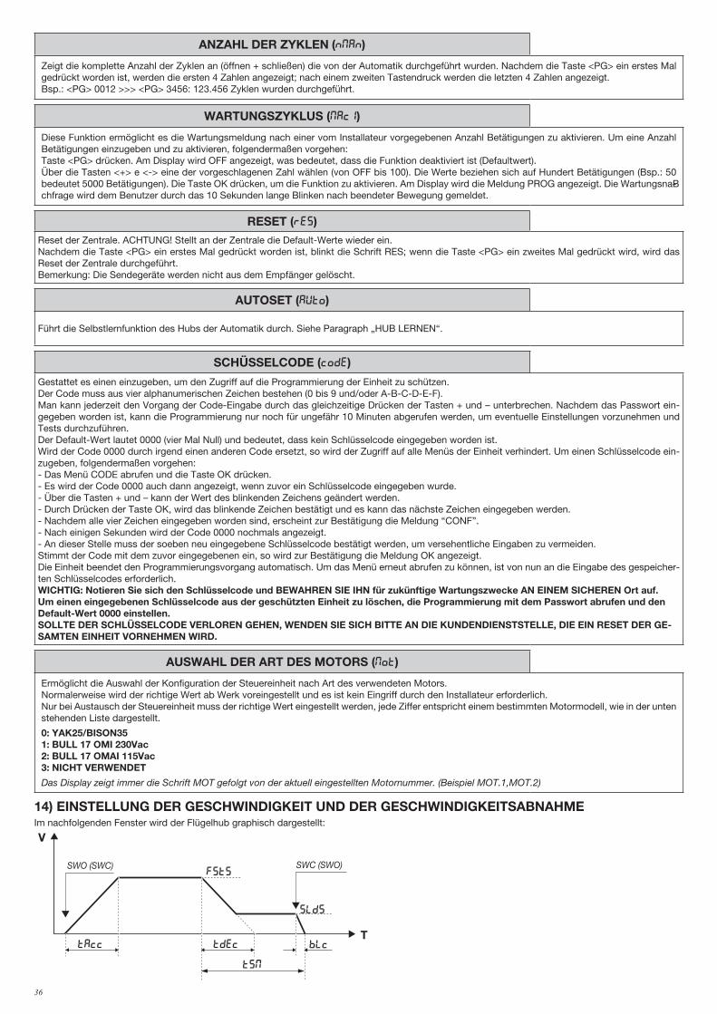
36
ANZAHL DER ZYKLEN (Nman)
Zeigt die komplette Anzahl der Zyklen an (öffnen + schließen) die von der Automatik durchgeführt wurden. Nachdem die Taste <PG> ein erstes Mal gedrückt worden ist, werden die ersten 4 Zahlen angezeigt; nach einem zweiten Tastendruck werden die letzten 4 Zahlen angezeigt.Bsp.: <PG> 0012 >>> <PG> 3456: 123.456 Zyklen wurden durchgeführt.
WARTUNGSZYKLUS (maci)
Diese Funktion ermöglicht es die Wartungsmeldung nach einer vom Installateur vorgegebenen Anzahl Betätigungen zu aktivieren. Um eine Anzahl Betätigungen einzugeben und zu aktivieren, folgendermaßen vorgehen:Taste <PG> drücken. Am Display wird OFF angezeigt, was bedeutet, dass die Funktion deaktiviert ist (Defaultwert). Über die Tasten <+> e <-> eine der vorgeschlagenen Zahl wählen (von OFF bis 100). Die Werte beziehen sich auf Hundert Betätigungen (Bsp.: 50 bedeutet 5000 Betätigungen). Die Taste OK drücken, um die Funktion zu aktivieren. Am Display wird die Meldung PROG angezeigt. Die WartungsnaB-chfrage wird dem Benutzer durch das 10 Sekunden lange Blinken nach beendeter Bewegung gemeldet.
RESET (RES)Reset der Zentrale. ACHTUNG! Stellt an der Zentrale die Default-Werte wieder ein.Nachdem die Taste <PG> ein erstes Mal gedrückt worden ist, blinkt die Schrift RES; wenn die Taste <PG> ein zweites Mal gedrückt wird, wird das Reset der Zentrale durchgeführt.Bemerkung: Die Sendegeräte werden nicht aus dem Empfänger gelöscht.
AUTOSET (AUTO)
Führt die Selbstlernfunktion des Hubs der Automatik durch. Siehe Paragraph „HUB LERNEN“.
SCHÜSSELCODE (codE)
Gestattet es einen einzugeben, um den Zugriff auf die Programmierung der Einheit zu schützen.Der Code muss aus vier alphanumerischen Zeichen bestehen (0 bis 9 und/oder A-B-C-D-E-F).Man kann jederzeit den Vorgang der Code-Eingabe durch das gleichzeitige Drücken der Tasten + und – unterbrechen. Nachdem das Passwort ein-gegeben worden ist, kann die Programmierung nur noch für ungefähr 10 Minuten abgerufen werden, um eventuelle Einstellungen vorzunehmen und Tests durchzuführen.Der Default-Wert lautet 0000 (vier Mal Null) und bedeutet, dass kein Schlüsselcode eingegeben worden ist.Wird der Code 0000 durch irgend einen anderen Code ersetzt, so wird der Zugriff auf alle Menüs der Einheit verhindert. Um einen Schlüsselcode ein-zugeben, folgendermaßen vorgehen:- Das Menü CODE abrufen und die Taste OK drücken.- Es wird der Code 0000 auch dann angezeigt, wenn zuvor ein Schlüsselcode eingegeben wurde.- Über die Tasten + und – kann der Wert des blinkenden Zeichens geändert werden.- Durch Drücken der Taste OK, wird das blinkende Zeichen bestätigt und es kann das nächste Zeichen eingegeben werden.- Nachdem alle vier Zeichen eingegeben worden sind, erscheint zur Bestätigung die Meldung “CONF”.- Nach einigen Sekunden wird der Code 0000 nochmals angezeigt.- An dieser Stelle muss der soeben neu eingegebene Schlüsselcode bestätigt werden, um versehentliche Eingaben zu vermeiden.Stimmt der Code mit dem zuvor eingegebenen ein, so wird zur Bestätigung die Meldung OK angezeigt.Die Einheit beendet den Programmierungsvorgang automatisch. Um das Menü erneut abrufen zu können, ist von nun an die Eingabe des gespeicher-ten Schlüsselcodes erforderlich.WICHTIG: Notieren Sie sich den Schlüsselcode und BEWAHREN SIE IHN für zukünftige Wartungszwecke AN EINEM SICHEREN Ort auf. Um einen eingegebenen Schlüsselcode aus der geschützten Einheit zu löschen, die Programmierung mit dem Passwort abrufen und den Default-Wert 0000 einstellen.SOLLTE DER SCHLÜSSELCODE VERLOREN GEHEN, WENDEN SIE SICH BITTE AN DIE KUNDENDIENSTSTELLE, DIE EIN RESET DER GE-SAMTEN EINHEIT VORNEHMEN WIRD.
AUSWAHL DER ART DES MOTORS (mot)
Ermöglicht die Auswahl der Konfiguration der Steuereinheit nach Art des verwendeten Motors.Normalerweise wird der richtige Wert ab Werk voreingestellt und es ist kein Eingriff durch den Installateur erforderlich.Nur bei Austausch der Steuereinheit muss der richtige Wert eingestellt werden, jede Ziffer entspricht einem bestimmten Motormodell, wie in der unten stehenden Liste dargestellt.
0: YAK25/BISON351: BULL 17 OMI 230Vac2: BULL 17 OMAI 115Vac3: NICHT VERWENDET
Das Display zeigt immer die Schrift MOT gefolgt von der aktuell eingestellten Motornummer. (Beispiel MOT.1,MOT.2)
14) EINSTELLUNG DER GESCHWINDIGKEIT UND DER GESCHWINDIGKEITSABNAHMEIm nachfolgenden Fenster wird der Flügelhub graphisch dargestellt:
V
T
FSTS
slds
BLcTAcc Tdec
TSM
SWO (SWC) SWC (SWO)
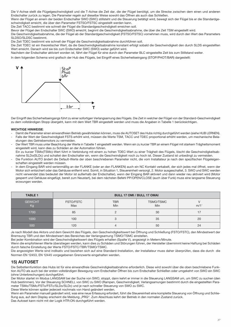
37
Die V-Achse stellt die Flügelgeschwindigkeit und die T-Achse die Zeit dar, die der Flügel benötigt, um die Strecke zwischen dem einen und anderen Endschalter zurück zu legen. Die Parameter regeln auf dieselbe Weise sowohl das Öffnen als auch das Schließen. Wenn der Flügel an einem der beiden Endschalter SWO (SWC) stillsteht und die Steuerung betätigt wird, bewegt sich der Flügel bis er die Standardge-schwindigkeit erreicht, die über den Parameter FSTSO/FSTSC eingestellt werden kann. Die Zeit TACC bestimmt wie schnell der Flügel die Standardgeschwindigkeit erreichen soll.Bevor der Flügel den Endschalter SWC (SWO) erreicht, beginnt die Geschwindigkeitsabnahme, die über die Zeit TSM eingestellt wird.Die Geschwindigkeitsabnahme, die der Flügel ab der Standardgeschwindigkeit (FSTSO/FSTSC) vornehmen muss, wird durch den Wert des Parameters SLDSO/SLDSC bestimmt.Die Zeit TDEC bestimmt wie schnell der Flügel die Geschwindigkeitsabnahme durchführen soll.Die Zeit TDEC ist ein theoretischer Wert, da die Geschwindigkeitsabnahme konstant erfolgt sobald die Geschwindigkeit den durch SLDS eingestellten Wert erreicht. Danach wird sie bis zum Endschalter SWC (SWO) weiter geführt wird.Nachdem der Endschalter aktiviert worden ist, fährt der Flügel für eine durch den Parameter BLC eingestellte Zeit bis zum Stillstand weiter.
In dem folgenden Schema wird grafisch der Hub des Flügels, bei Eingriff eines Sicherheitseingang (STOP/PHOT/BAR) dargestellt:
V
T
FSTo/fstc
sldo/SldC
BLo/blcTAcc Tdec
TSMo/tsmc
SWO (SWC) SWC (SWO)
V
Ttbr
stopphotbar
Der Eingriff des Sicherheitseingangs führt zu einer sofortigen Verlangsamung des Flügels. Die Zeit in welcher der Flügel von der Standard-Geschwindigkeit zu dem vollständigen Stopp übergeht, kann mit dem Wert TBR eingestellt werden und muss die Angaben in Tabelle 1 berücksichtigen.
WICHTIGE HINWEISE:- Damit die Parameter einen einwandfreien Betrieb gewährleisten können, muss die AUTOSET des Hubs richtig durchgeführt werden (siehe HUB LERNEN).- Falls der Wert der Geschwindigkeit FSTS erhöht wird, müssen die Werte TSM, TACC und TDEC proportional erhöht werden, um mechanische Bela-
stungen des Getriebemotors zu vermeiden.- Der Wert TBR muss unter Beachtung der Werte in Tabelle 1 eingestellt werden. Wenn ein zu kurzer TBR an einem Flügel mit starkem Trägheitsmoment
eingestellt wird, kann dies zu Schäden an der Automation führen. Ein zu kurzer TSMo(TSMc)-Wert führt in Verbindung mit einem zu hohen TDEC-Wert zu einer Trägheit des Flügels, löscht die Geschwindigkeitsab-
nahme SLDo(SLDc) und schaltet den Endschalter ein, wenn die Geschwindigkeit noch zu hoch ist. Dieser Zustand ist unbedingt zu vermeiden.- Die Funktion AUTO ändert die Default-Werte der oben beschriebenen Parameter nicht, die vom Installateur je nach den spezifischen Flügeleigen-
schaften eingestellt werden müssen.- In dem Eingang BAR wird serienmäßig an der FLANKE (oder an den FLANKEN) auch ein NC Kontakt verkabelt, der sich jedes mal öffnet, wenn der
Motor sich entsichert oder das Gehäuse entfernt wird. Somit, in Situation 1, Steuereinheit versorgt, 2. Motor ausgeschaltet, 3. SWO und SWC werden nicht verwendet (das bedeutet der Motor ist außerhalb der Endschalter), wenn der Eingang BAR aktiviert und dann wieder neu aktiviert wird (Motor gesperrt und Gehäuse eingefügt, bereit zum Neustart), bei dem nächsten Befehl PP/OPEN/CLOSE (auch über Funk) muss eine langsame Steuerung erzwungen werden.
TABLE 1 BULL 17 OMI / BULL 17 OMAI
GEWICHTKg
FSTO/FSTCMax
TBRMin
TSMO/TSMCMin
Vm/1'
1700 85 2 30 17
1000 100 3 35 20
500 120 4 50 24
Je nach Modell des Aktors und dem Gewicht des Flügels, den Geschwindigkeitswert bei Öffnung und Schließung (FSTO/FSTC), den Mindestwert der Bremsung TBR und den Mindestwert des Bereiches der Verlangsamung TSMO/TSMC einstellen.Bei jeder Kombination wird der Geschwindigkeitswert des Flügels erhalten (Spalte V), angezeigt in Metern/Minute.Wenn die empfohlenen Werte überstiegen werden, kann dies zu Schäden und Störungen führen, der Hersteller übernimmt keine Haftung bei Schäden durch falsche Einstellung der Werte FSTO/FSTC/TBR/TSMO/TSMC.Die angezeigten Werte sind indikativ und beziehen sich auf eine Standard-Installation, der Installateur muss daher überprüfen, dass die durch die Normen EN 12453, EN 12445 vorgegebenen Grenzwerte eingehalten werden.
15) AUTOSETDie Selbstlernfunktion des Hubs ist für eine einwandfreie Geschwindigkeitsabnahme erforderlich. Diese wird sowohl über die oben beschriebene Funk-tion AUTO als auch bei der ersten vollständigen Bewegung vom Endschalter Öffnen bis zum Endschalter Schließen oder umgekehrt von SWO ein SWC (ohne Unterbrechungen) durchgeführt.Der Motor startet im Modus LANGSAM bei der Suche von SWO, stoppt, dann kehrt er immer in die Steuerung LANGSAM um, um SWC zu suchen (den Hub bestimmen). Vor der Steuerung SCHNELL von SWC zu SWO (Rampen, Geschwindigkeit, Verlangsamungen bestimmt durch die eingestellten Para-meter TSMo/TSMc/FSTo/FSTc/SLDo/SLDc) und je nach schneller Steuerung von SWO zu SWC.Diese Werte können später jederzeit nochmals von Hand geändert werden.Wenn ein Parameter manuell geändert wird, was eine neue Erfassung erfordert, führt die Steuereinheit eine komplette Steuerung von Öffnung und Schlie-ßung aus, auf dem Display erscheint die Meldung „PRG“. Zum Abschluss kehrt der Betrieb in den normalen Zustand zurück.Das Autoset kann nicht mit der Logik HTR:ON durchgeführt werden.

38
16) FEHLERMELDUNGENIn der Folge werden einige Meldungen aufgeführt, die am Display im Falle von Betriebsstörungen angezeigt werden:
ERR Fehler Eingänge N.O (Autoset)Wenn der Fehler während der Selbstlernfunktion stattfindet, den Zustand der Eingänge PP/PED/OPED/BAR kontrollieren.
Err1 Fehler STOP (Autoset) Eingriff von STOP während Autoset.
Err2 Fehler Fotozellen (Autoset) Eingriff von PHOTO/PHOTC während Autoset.
Err4 Fehler Näherungsflanke (Autoset) Eingriff BAR während Autoset.
Err5 Fehler Fototest Den Betrieb und den richtigen Anschluss der Fotozellen prüfen.
AMP Stromsensor eingeschaltetDer Stromsensor wurde durch ein Hindernis oder einen Widerstand eingeschaltet. Das Hinder-nis entfernen oder den Flügelhub prüfen.
F01 Die angeschlossene Bremse verbraucht zu viel.
F02Kurzschluss an Motor. Impedanz der Wicklungen und Isolierung zwischen jeder Phase des Motors und der Masse prüfen.
F04Bei Einschalten kehrt die Bus-Spannung nicht zu den Vorgaben zurück. Die Versorgungsspan-nung prüfen, oder die richtige Auswahl des Motors gemäß dem Menü Mot.
F05 Erfasste Übertemperatur in der Steuereinheit.
F06Überschrittener des momentanen Schwellenstrom. Den Motor entriegeln und prüfen, dass der Kolben sich frei dreht. Bei Bedarf den technischen Kundendienst kontaktieren.
F07
Überschrittener des momentanen Schwellenstrom. Den Motor entriegeln und prüfen, dass ent-lang dem gesamten Hub des Tors keine übermäßigen Lasten vorliegen (schwierig zu bewegen). Bei Bedarf den technischen Kundendienst kontaktieren.
F08
Maximal zulässige Spannung an Leistungsbus überschritten. Die Versorgungsspannung über-prüfen. In der angegebenen Reihenfolge die folgenden Arbeiten durchführen:1. Die Parameter TDEC und TSMO/TSMC erhöhen, Zwischenstopps mit Steuerungen STOP/PP/PHOT/BAR prüfen, wenn das Problem weiter besteht, zu dem folgenden Punkt übergehen:2. Den Parameter TBRerhöhen, Zwischenstopps mit Steuerungen STOP/PP/PHOT/BAR prüfen, wenn das Problem weiter besteht, zu dem folgenden Punkt übergehen:3. Den Bremswiderstand anschließen, die Zwischenstopps mit Steuerungen STOP/PP/PHOT/BAR prüfen, wenn das Problem weiter besteht, zu dem folgenden Punkt übergehen:4. Die Parameter FSTO/FSTC verringern, Zwischenstopps mit Steuerungen STOP/PP/PHOT/BAR prüfen.
F09
Die eingestellten Werte sind nicht korrekt und der Flügel geht über den Endschalter.In der Reihenfolge die folgenden Parameter ändern:- blo / blc (verringern)- tsmo / tsmc (erhöhen)- sldo / sldc (verringern)- fsto / fstc (verringern)
17) LCD DISPLAYFalls erforderlich, kann die LCD um 180 ° drehbar.- Stromversorgung des Netzes abtrennen.- Taste PGM drücken.- Die taste PGM gedrückt halten und wieder Strom geben- Die Taste PGM gedrückt halten (ca. 5s) bis die Softwareversion um 180° gedreht erscheint. Mit der Programmierung wie üblich fortfahren.
18) DIAGNOSEBei Betriebsstörungen kann auf dem Display der Status aller Eingänge angezeigt werden (Endschalter, Steuerung und Sicherheit).Jedem Eingang ist ein Displaysegment zugeteilt, das bei der Aktivierung laut nachstehendem Schema aufleuchtet.
PHOTO
SWC
STOP
SWO
PHOTC BAR
P.P. PED OPEN CLOSE
LD1 LED: Vorhandensein Netzversorgung.LD2 LED: VORHANDENSEIN + 5VPHOTO: PHOT1/TST1PHOTC: PHOT2/TST2F4: Sicherung Versorgungsleitung 15AT.
39
19) WARTUNGIn der folgenden Tabelle werden die Wartungseingriffe, Ausbesserungen oder Reparaturen durch Fachpersonal verzeichnet.
Datum _ _ _ _ _ _ _ _ _ _ _ _ _ _ _ _ _ _ _ _ _ _ _ _ _ _ _ _ _ _ _ _ Unterschrift des technikers _ _ _ _ _ _ _ _ _ _ _ _ _ _ _ _ _ _ _ _ Stempel
Beschreibung des eingriffs
_ _ _ _ _ _ _ _ _ _ _ _ _ _ _ _ _ _ _ _ _ _ _ _ _ _ _ _ _ _ _ _ _ _ _ _ _ _ _ _ _ _ _ _ _ _ _ _ _ _ _ _ _ _ _ _ _ _ _ _ _ _ _ _ _ _ _ _ _ _ _ _ _
_ _ _ _ _ _ _ _ _ _ _ _ _ _ _ _ _ _ _ _ _ _ _ _ _ _ _ _ _ _ _ _ _ _ _ _ _ _ _ _ _ _ _ _ _ _ _ _ _ _ _ _ _ _ _ _ _ _ _ _ _ _ _ _ _ _ _ _ _ _ _ _ _
40
FRA AVERTISSEMENTSINFORMATIONS GÉNÉRALES Il est interdit d’utiliser ce produit pour l’utilisation du produit ou avec des finalités ou modalités non prévues par le présent manuel. Toute autre utilisation pourrait compromettre l’intégrité du produit et présenter un danger pour les personnes ou pour les biens.Le fabricant décline toute responsabilité en cas d’utilisation impropre ou d’inobservation de la bonne technique dans la construction des portails, ainsi que de toute déformation qui pourrait avoir lieu lors de son utilisation. Toujours conserver la notice pour toute autre consultation future.
GUIDE INSTALLATEURCe manuel est destiné exclusivement au personnel qualifié pour l’installation et la maintenance des ouvertures automatiques.Le montage doit être accompli par du personnel qualifié (monteur professionnel, conformément à EN12635), dans le respect del la bonne technique et des normes en vigueur. Vérifier que la structure du portail est adaptée pour être équipée d’un automatisme. L’installateur doit fournir toutes les informations relatives au fonctionnement automatique, au déverrouillage d’urgence de l’automatisme, et livrer à l’utilisateur les modes d’emploi.
AVERTISSEMENTS GÉNÉRAUX Tenir à l’écart des enfants tous les matériaux d’emballage car ils représentent une source potentielle de danger. Ne pas disperser les matériaux d’emballage dans l’environnement, mais trier selon les différentes typologies (i.e. carton, polystyrène) et les traiter selon les normes locales.Ne pas laisser les enfants jouer avec les dispositifs de commande du produit. Conserver les télécommandes hors de la portée des enfants. Ce produit n’est pas prévu pour être utilisé par des personnes (dont les enfants) dont les capacités physiques, sensorielles ou mentales sont limitées, ou ne disposant pas des connaissances adéquates, sauf sous surveillance ou après avoir reçu les consignes des personnes responsables de leur sécurité. Appliquer tous les dispositifs de sécurité (photocellules, linteaux sensibles, etc..) nécessaires pour protéger la zone contre les risques de choc, d’écrasement, d’entraînement ou de cisaillement. Tenir compte des réglements et des directives en vigueur, des critéres de bonne technique, de l’utilisation, de l’environnement de l’installation, de la logique de functionnement du système et des forces développées par l’automatisation.L’installation doit être équipée de dispositifs de sécurité et de commandes conformes aux normes EN 12978 et EN 12453.Utiliser exclusivement des accessoires et des pièces de rechange originales, l’utilisation de composants non originaux comporte l’exclusion du produit des couvertures prévues par le certificat de Garantie.Toutes la parties, mécaniques et électriques, qui composent l'automation doivent correspondre aux conditions requises des réglementations en vigueur et reporter le marquage CE.
SÉCURITÉ ÉLECTRIQUE Prévoir sur le réseau de l’alimentation un interrupteur / sectionneur omnipolaire avec distance d’ouverture des contacts égale ou supérieure à 3 mm. Vérifier la présence en amont de l’installation électrique d’un interrupteur différentiel et d’une protection de surcourant adéquats.Certains types d’installation requièrent le branchement du vantail à une installation de mise à terre satisfaisant les normes de sécurité e vigueur.Avant toute intervention, d’installation, réparation et maintien, couper l’alimentation avant d’accéder aux parties électriques. Déconnecter également les batteries tempon éventuellement présentes. L’installation électrique et la logique de fonctionnement doivent être conformes aux normes en vigueur. Les conducteurs alimentés à des tensions différentes doivent être séparés physiquement ou bien, ils doivent être isolés en manière appropriée avec une gaine supplémentaire d’au moins 1 mm. Les conducteurs doivent être assurés par une fixation supplémen-taire à proximité des bornes. Pendant toute intervention d’installation, maintenance et réparation, couper l’alimentation avant de procéder à toucher les parties électriques. Recontrôler toutes les connexions faites avant d’alimenter la logique de commande. Les entrées N.F. non utilisées doivent être shuntées
DÉMOLITIONComme indiqué par le symbole à coté, il est interdit de jeter ce produit dans les ordures ménagères car les parties qui le composent pourraient nuire à l’environnent et à la santé des hommes, si traitées et évacuées de manière incorrecte. L’appareillage devra, par conséquent, être livré dans les spéciaux point de collecte et de triage, ou bien remis au revendeur lorsqu’on décide d’acheter un appareillage équivalent. L’évacu-ation abusive du produit de la part de l’usager comporte l’application de sanctions administratives comme prévu par les normes en vigueur.
Les descriptions et les illustrations présentées dans ce manuel ne sont pas contraignantes. En laissant inaltérées les caractéristiques essentielles du produit, le fabricant se réserve le droit d’apporter toute modification à caractère technique, de construction ou commerciale sans s’engager à revoir la cette publication.
ATTENTION!L'unité de commande utilise des condensateurs à haute capacité qui peut être dangereux même en l'absence d'alimentation secteur. Il est indispensable d'attendre au moins 60 secondes après la déconnexion de l'alimentation secteur avant d'accéder à l'unité de commande.
Read Instructions
DO NOT TOUCH!DISCONNECT M A I N S U P P LY WAIT!
60 sec.
WARNING!
F8369256
Etichetta WARNING: Formato 55x50mm
stampa su PVC adesivo4 colori
Read Instructions
DO NOT TOUCH!DISCONNECT M A I N S U P P LY WAIT!
60 sec.
WARNING!
F8369256
Etichetta WARNING: Formato 55x50mm
stampa su PVC adesivo4 colori
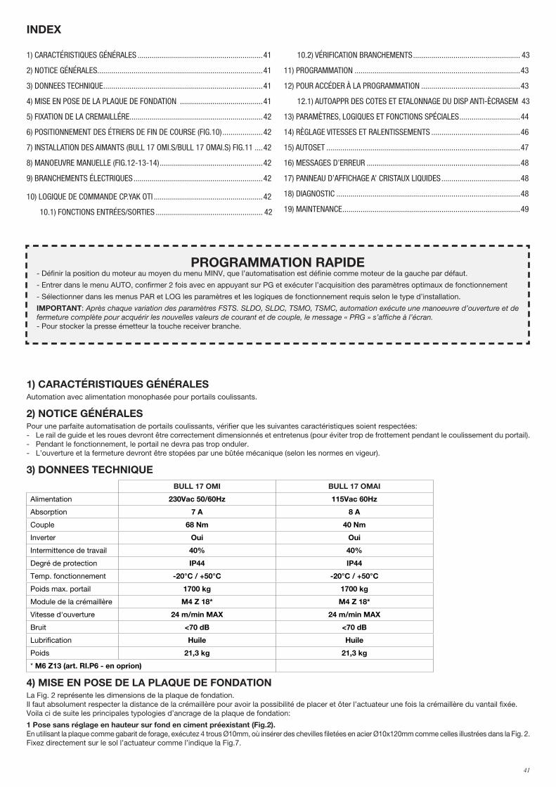
41
1) CARACTÉRISTIQUES GÉNÉRALESAutomation avec alimentation monophasée pour portails coulissants.
2) NOTICE GÉNÉRALESPour une parfaite automatisation de portails coulissants, vérifier que les suivantes caractéristiques soient respectées:- Le rail de guide et les roues devront être correctement dimensionnés et entretenus (pour éviter trop de frottement pendant le coulissement du portail).- Pendant le fonctionnement, le portail ne devra pas trop onduler.- L’ouverture et la fermeture devront être stopées par une bûtée mécanique (selon les normes en vigeur).
3) DONNEES TECHNIQUE
BULL 17 OMI BULL 17 OMAI
Alimentation 230Vac 50/60Hz 115Vac 60Hz
Absorption 7 A 8 A
Couple 68 Nm 40 Nm
Inverter Oui Oui
Intermittence de travail 40% 40%
Degré de protection IP44 IP44
Temp. fonctionnement -20°C / +50°C -20°C / +50°C
Poids max. portail 1700 kg 1700 kg
Module de la crémaillère M4 Z 18* M4 Z 18*
Vitesse d'ouverture 24 m/min MAX 24 m/min MAX
Bruit <70 dB <70 dB
Lubrification Huile Huile
Poids 21,3 kg 21,3 kg
* M6 Z13 (art. RI.P6 - en oprion)
4) MISE EN POSE DE LA PLAQUE DE FONDATION La Fig. 2 représente les dimensions de la plaque de fondation.Il faut absolument respecter la distance de la crémaillère pour avoir la possibilité de placer et ôter l’actuateur une fois la crémaillère du vantail fixée.Voila ci de suite les principales typologies d’ancrage de la plaque de fondation:
1 Pose sans réglage en hauteur sur fond en ciment préexistant (Fig.2). En utilisant la plaque comme gabarit de forage, exécutez 4 trous Ø10mm, où insérer des chevilles filetées en acier Ø10x120mm comme celles illustrées dans la Fig. 2. Fixez directement sur le sol l’actuateur comme l’indique la Fig.7.
1) CARACTÉRISTIQUES GÉNÉRALES ..............................................................41
2) NOTICE GÉNÉRALES..................................................................................41
3) DONNEES TECHNIQUE ...............................................................................41
4) MISE EN POSE DE LA PLAQUE DE FONDATION .........................................41
5) FIXATION DE LA CREMAILLÉRE ..................................................................42
6) POSITIONNEMENT DES ÉTRIERS DE FIN DE COURSE (FIG.10) ....................42
7) INSTALLATION DES AIMANTS (BULL 17 OMI.S/BULL 17 OMAI.S) FIG.11 ....42
8) MANOEUVRE MANUELLE (FIG.12-13-14) ...................................................42
9) BRANCHEMENTS ÉLECTRIQUES ................................................................42
10) LOGIQUE DE COMMANDE CP.YAK OTI ......................................................42
10.1) FONCTIONS ENTRÉES/SORTIES ..................................................... 42
10.2) VÉRIFICATION BRANCHEMENTS ..................................................... 43
11) PROGRAMMATION ..................................................................................43
12) POUR ACCÉDER À LA PROGRAMMATION .................................................43
12.1) AUTOAPPR DES COTES ET ETALONNAGE DU DISP ANTI-ÈCRASEM 43
13) PARAMÈTRES, LOGIQUES ET FONCTIONS SPÉCIALES ..............................44
14) RÈGLAGE VITESSES ET RALENTISSEMENTS ............................................46
15) AUTOSET ................................................................................................47
16) MESSAGES D’ERREUR ............................................................................48
17) PANNEAU D’AFFICHAGE A’ CRISTAUX LIQUIDES .......................................48
18) DIAGNOSTIC ...........................................................................................48
19) MAINTENANCE ........................................................................................49
INDEX
PROGRAMMATION RAPIDE- Définir la position du moteur au moyen du menu MINV, que l’automatisation est définie comme moteur de la gauche par défaut.
- Entrer dans le menu AUTO, confirmer 2 fois avec en appuyant sur PG et exécuter l’acquisition des paramètres optimaux de fonctionnement
- Sélectionner dans les menus PAR et LOG les paramètres et les logiques de fonctionnement requis selon le type d’installation.
IMPORTANT: Après chaque variation des paramètres FSTS. SLDO, SLDC, TSMO, TSMC, automation exécute une manoeuvre d’ouverture et de fermeture complète pour acquérir les nouvelles valeurs de courant et de couple, le message « PRG » s’affiche à l’écran.- Pour stocker la presse émetteur la touche receiver branche.
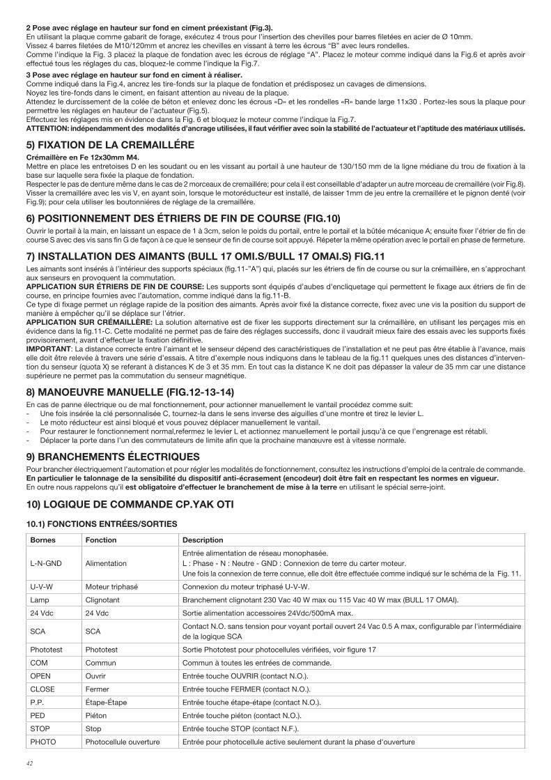
42
2 Pose avec réglage en hauteur sur fond en ciment préexistant (Fig.3). En utilisant la plaque comme gabarit de forage, exécutez 4 trous pour l’insertion des chevilles pour barres filetées en acier de Ø 10mm.Vissez 4 barres filetées de M10/120mm et ancrez les chevilles en vissant à terre les écrous “B” avec leurs rondelles.Comme l’indique la Fig. 3 placez la plaque de fondation avec les écrous de réglage “A”. Placez le moteur comme indiqué dans la Fig.6 et après avoir effectué tous les réglages du cas, bloquez-le comme l’indique la Fig.7.
3 Pose avec réglage en hauteur sur fond en ciment à réaliser. Comme indiqué dans la Fig.4, ancrez les tire-fonds sur la plaque de fondation et prédisposez un cavages de dimensions.Noyez les tire-fonds dans le ciment, en faisant attention au niveau de la plaque. Attendez le durcissement de la colée de béton et enlevez donc les écrous «D» et les rondelles «R» bande large 11x30 . Portez-les sous la plaque pour permettre les réglages en hauteur de l’actuateur (Fig.5).Effectuez les réglages mis en évidence dans la Fig. 6 et bloquez le moteur comme l’indique la Fig.7.ATTENTION: indépendamment des modalités d’ancrage utilisées, il faut vérifier avec soin la stabilité de l’actuateur et l’aptitude des matériaux utilisés.
5) FIXATION DE LA CREMAILLÉRECrémaillère en Fe 12x30mm M4.Mettre en place les entretoises D en les soudant ou en les vissant au portail à une hauteur de 130/150 mm de la ligne médiane du trou de fixation à la base sur laquelle sera fixée la plaque de fondation. Respecter le pas de denture même dans le cas de 2 morceaux de cremaillére; pour cela il est conseillable d’adapter un autre morceau de cremaillére (voir Fig.8).Visser la cremaillére avec les vis V, en ayant soin, lorsque le motoréducteur est installé, de laisser 1mm de jeu entre la cremaillére et le pignon denté (voir Fig.9); pour cela utiliser les boutonniéres de réglage de la cremaillére.
6) POSITIONNEMENT DES ÉTRIERS DE FIN DE COURSE (FIG.10)Ouvrir le portail à la main, en laissant un espace de 1 à 3cm, selon le poids du portail, entre le portail et la bûtée mécanique A; ensuite fixer l’étrier de fin de course S avec des vis sans fin G de façon à ce que le senseur de fin de course soit appuyé. Répeter la même opération avec le portail en phase de fermeture.
7) INSTALLATION DES AIMANTS (BULL 17 OMI.S/BULL 17 OMAI.S) FIG.11Les aimants sont insérés à l’intérieur des supports spéciaux (fig.11-”A”) qui, placés sur les étriers de fin de course ou sur la crémaillère, en s’approchant aux senseurs en provoquent la commutation.APPLICATION SUR ÉTRIERS DE FIN DE COURSE: Les supports sont équipés d’aubes d’encliquetage qui permettent Ie fixage aux étriers de fin de course, en principe fournies avec l’automation, comme indiqué dans la fig.11-B.Ce type di fixage permet un réglage rapide de la position des aimants. Après avoir fixé la distance correcte, fixez avec une vis la position du support de manière à empêcher qu’il se déplace sur l’étrier.APPLICATION SUR CRÉMAILLÈRE: La solution alternative est de fixer les supports directement sur la crémaillère, en utilisant les perçages mis en évidence dans la fig.11-C. Cette modalité ne permet pas de faire des réglages successifs, donc il vaudrait mieux faire des essais avec les supports fixés provisoirement, avant d’effectuer la fixation définitive.IMPORTANT: La distance correcte entre l’aimant et le senseur dépend des caractéristiques de l’installation et ne peut pas être établie à l’avance, mais elle doit être relevée à travers une série d’essais. A titre d’exemple nous indiquons dans le tableau de la fig.11 quelques unes des distances d’interven-tion du senseur (quota X) se referant à distances K de 3 et 35 mm. En tout cas la distance K ne doit pas dépasser la valeur de 35 mm car une distance supérieure ne permet pas la commutation du senseur magnétique.
8) MANOEUVRE MANUELLE (FIG.12-13-14)En cas de panne électrique ou de mal fonctionnement, pour actionner manuellement le vantail procédez comme suit: - Une fois insérée la clé personnalisée C, tournez-la dans le sens inverse des aiguilles d’une montre et tirez le levier L.- Le moto réducteur est ainsi bloqué et vous pouvez déplacer manuellement le vantail.- Pour restaurer le fonctionnement normal,refermez le levier L et actionnez manuellement le portail jusqu’à ce que l’engrenage est rétabli.- Déplacer la porte dans l’un des commutateurs de limite afin que la prochaine manœuvre est à vitesse normale.
9) BRANCHEMENTS ÉLECTRIQUESPour brancher électriquement l’automation et pour régler les modalités de fonctionnement, consultez les instructions d’emploi de la centrale de commande.En particulier le talonnage de la sensibilité du dispositif anti-écrasement (encodeur) doit être fait en respectant les normes en vigueur.En outre nous rappelons qu’il est obligatoire d’effectuer le branchement de mise à la terre en utilisant le spécial serre-joint.
10) LOGIQUE DE COMMANDE CP.YAK OTI
10.1) FONCTIONS ENTRÉES/SORTIES
Bornes Fonction Description
L-N-GND AlimentationEntrée alimentation de réseau monophasée.L : Phase - N : Neutre - GND : Connexion de terre du carter moteur.Une fois la connexion de terre connue, elle doit être effectuée comme indiqué sur le schéma de la Fig. 11.
U-V-W Moteur triphasé Connexion du moteur triphasé U-V-W.
Lamp Clignotant Branchement clignotant 230 Vac 40 W max ou 115 Vac 40 W max (BULL 17 OMAI).
24 Vdc 24 Vdc Sortie alimentation accessoires 24Vdc/500mA max.
SCA SCAContact N.O. sans tension pour voyant portail ouvert 24 Vac 0.5 A max, configurable par l'intermédiaire de la logique SCA
Phototest Phototest Sortie Phototest pour photocellules vérifiées, voir figure 17
COM Commun Commun à toutes les entrées de commande.
OPEN Ouvrir Entrée touche OUVRIR (contact N.O.).
CLOSE Fermer Entrée touche FERMER (contact N.O.).
P.P. Étape-Étape Entrée touche étape-étape (contact N.O.).
PED Piéton Entrée touche piéton (contact N.O.).
STOP Stop Entrée touche STOP (contact N.F.).
PHOTO Photocellule ouverture Entrée pour photocellule active seulement durant la phase d'ouverture

43
PHOTC Photocellule fermeture Entrée pour photocellule active seulement durant la phase de fermeture
COM Commun Commun pour butée.
SWC Butée Fermer Entrée butée FERMER (contact N.F.).
SWO Butée Ouvrir Entrée butée OUVRIR (contact N.F.).
BARBord sensible desécurité
Entrée contact bord sensibleCôté résistif (8K2) : JP1 « BAR » ferméCôté mécanique (N.F.) : JP1 « BAR » ouvertL’intervention du côté arrête le mouvement de la porte et inverse pendant environ 3 secondes.Remarque : cette entrée est connectée le transformateur de sécurité monté sur le levier de dégagement de main qui empêche toute manœuvre si le moteur libéré.Le bord sensible doit être raccordé en série avec ce micro-interrupteur, comme illustré à la Figure 21
RADIO Récepteur radio Raccord rapide pour récepteur radio prise.
2CH Second canal Sortie N.O. du second canal radio du récepteur radio. (max 24 Vac/dc 1A)
BRAKE Résistance FreinEntrée pour résistance de dissipation du courant de freinageLa résistance n’est utilisée que sur 230V BULL 17 OMI
P3 Non utilisé
CON1 Non utilisé
J7 Non utilisé
J8 Non utilisé
SW1 Dip1, Dip2 Maintenir sur ON
U1MÉMOIRE DE CONFIGURATION
Mémoire E-Eprom extractible. Elle contient toutes les configurations de la centrale (logiques, paramètres, etc.), radioémetteurs exclus. En cas de panne, il est possible d'extraire l'E-Eprom et de l'insérer dans une centrale différente, en évitant la reprogrammation.
10.2) VÉRIFICATION BRANCHEMENTS1) Couper l’alimentation.2) Débloquer manuellement le vantail, le porter à environ mi-course et le bloquer à nouveau.3) Rétablir l’alimentation.4) Donner une commande de pas-à-pas avec le bouton de commande <-> sur la centrale de commande (lorsque le panneau d’affichage LCD est éteint),
pour arrêter le vantail appuyer à nouveau sur <->.5) Le vantail doit bouger en ouverture, au cas contraire ensemble la logique MINV pour changer le sens d’ouverture (Defaulr MINV=OFF) moteur installé à gauche.
11) PROGRAMMATIONLa programmation des différentes fonctions de la logique de commande est effectuée en utilisant l’afficheur à cristaux liquides présent sur le tableau de la logique et en programmant les valeurs désirées dans les menus de programmation décrits ci-après. Le menu paramètres permet d’associer une valeur numérique à une fonction, comme pour un trimmer de réglage.Le menu des logiques permet d’activer ou de désactiver une fonction, comme pour le réglage d’un dip-switch.D’autres fonctions spéciales suivent les menus paramètres et logiques et peuvent varier suivant le type de logique de commande ou de version de logiciel.
12) POUR ACCÉDER À LA PROGRAMMATION1 - Presser la touche <PG>, l’afficheur présente le premier menu Paramètres “PAR”. 2 - Choisir avec la touche <+> ou <-> le menu que l’on souhaite sélectionner.3 - Presser la touche <PG>, l’afficheur présente la première fonction disponible dans le menu.4 - Choisir avec la touche <+> ou <-> la fonction que l’on souhaite sélectionner.5 - Presser la touche <PG>, l’afficheur montre la valeur actuellement programmée pour la fonction sélectionnée.6 - Choisir avec la touche <+> ou <-> la valeur que l’on souhaite attribuer à la fonction.7 - Presser la touche <PG>, l’afficheur montre le signal “PRG” qui indique que la programmation a eu lieu.
12.1) AUTOAPPRENTISSAGE DES COTES ET ETALONNAGE DU DISPOSITIF ANTI-ÈCRASEMENTSuite à l’installation de l’automatisme les conducteurs électriques et avoir programmé toutes les fonctions requises, il est nécessaire exécuter l’auto apprentissage des cotes et des couples. Allez dans le menu AUTO et appuyer sur la touche <PGM> L’afficheur présente PUSH. Appuyez encore sur la touche <PGM>: La procédure d’auto étalonnage commence: l’afficheur présente la sigle PRG et la procédure d’auto apprentis-sage commence, il faut attendre au moins 2 cycles complets pour que la course soit mémorisée. Terminée la procédure l’afficheur présente le mot OK. La procédure peut être exécutée indépendamment de la position du vantail et elle peut être interrompue à tout moment en appuyant simultanément sur les touches <+> et <->, ou à l’aide de l’intervention des entrées STOP/PHO/PHA/BAR/PP/PED. Une fois la Si la procédure n’aboutit pas à un résultat positif, le système affiche le message ERR, vérifier donc la présence d’éventuels obstacles ou points de friction sur le vantail.Vérifier à la fin de la phase d'auto-réglage la valeur des forces opérationnelles selon ce qui est prévu par EN12445 et EN12453. Si la valeur de la force est trop élevée, installer un bord conforme a EN12978.NOTES: La pression sur la touche <-> avec afficheur éteint signifie un impulsion P.P.La pression simultanée de <+> et <-> effectuée à l’intérieur d’un menu fonction permet de revenir au menu supérieur sans apporter de modification. Maintenir la pression sur la touche <+> ou sur la touche <-> pour accélérer l’incrémentation/décrémentation des valeurs.Après une attente de 30 s, la logique de commande sort du mode programmation et éteint l’afficheur.
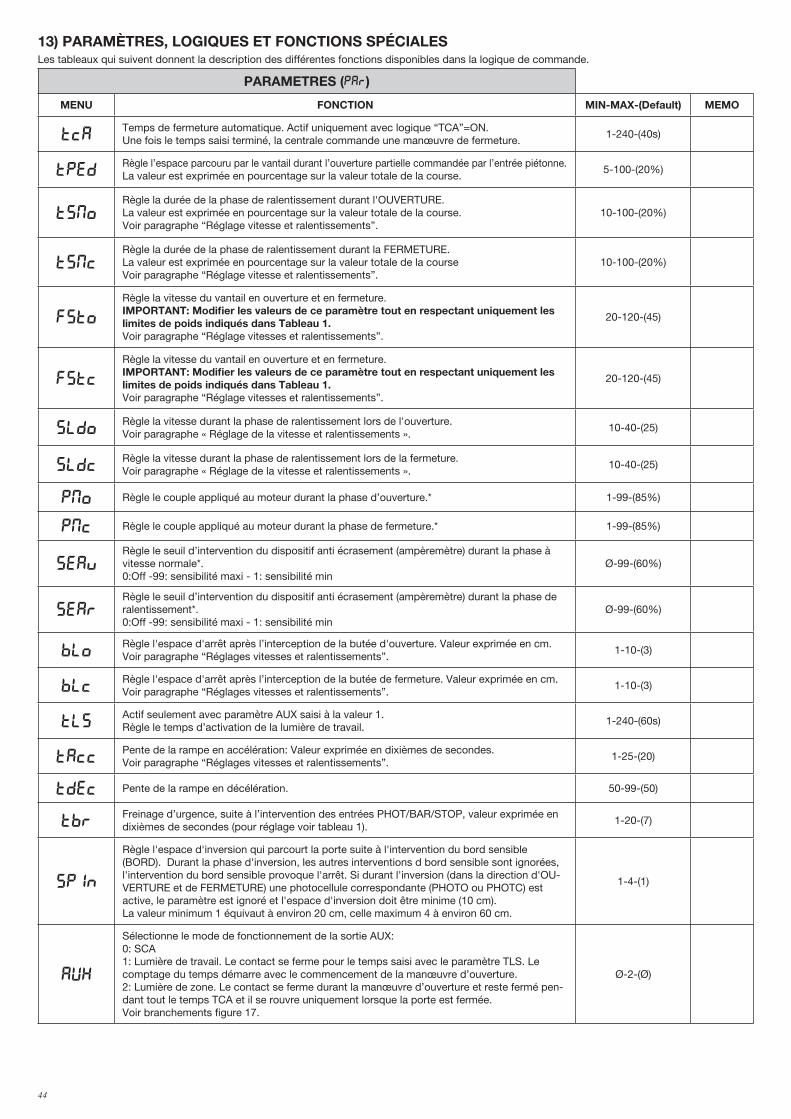
44
13) PARAMÈTRES, LOGIQUES ET FONCTIONS SPÉCIALESLes tableaux qui suivent donnent la description des différentes fonctions disponibles dans la logique de commande.
PARAMETRES (PAR)
MENU FONCTION MIN-MAX-(Default) MEMO
TCATemps de fermeture automatique. Actif uniquement avec logique “TCA”=ON.Une fois le temps saisi terminé, la centrale commande une manœuvre de fermeture.
1-240-(40s)
TpedRègle l’espace parcouru par le vantail durant l’ouverture partielle commandée par l’entrée piétonne. La valeur est exprimée en pourcentage sur la valeur totale de la course.
5-100-(20%)
tsmoRègle la durée de la phase de ralentissement durant l'OUVERTURE. La valeur est exprimée en pourcentage sur la valeur totale de la course.Voir paragraphe “Réglage vitesse et ralentissements”.
10-100-(20%)
TSMcRègle la durée de la phase de ralentissement durant la FERMETURE.La valeur est exprimée en pourcentage sur la valeur totale de la courseVoir paragraphe “Réglage vitesse et ralentissements”.
10-100-(20%)
FSTo
Règle la vitesse du vantail en ouverture et en fermeture.IMPORTANT: Modifier les valeurs de ce paramètre tout en respectant uniquement les limites de poids indiqués dans Tableau 1.Voir paragraphe “Réglage vitesses et ralentissements”.
20-120-(45)
fstc
Règle la vitesse du vantail en ouverture et en fermeture.IMPORTANT: Modifier les valeurs de ce paramètre tout en respectant uniquement les limites de poids indiqués dans Tableau 1.Voir paragraphe “Réglage vitesses et ralentissements”.
20-120-(45)
sldoRègle la vitesse durant la phase de ralentissement lors de l'ouverture.Voir paragraphe « Réglage de la vitesse et ralentissements ».
10-40-(25)
sldcRègle la vitesse durant la phase de ralentissement lors de la fermeture.Voir paragraphe « Réglage de la vitesse et ralentissements ».
10-40-(25)
PMO Règle le couple appliqué au moteur durant la phase d’ouverture.* 1-99-(85%)
PMC Règle le couple appliqué au moteur durant la phase de fermeture.* 1-99-(85%)
sEavRègle le seuil d’intervention du dispositif anti écrasement (ampèremètre) durant la phase à vitesse normale*. 0:Off -99: sensibilité maxi - 1: sensibilité min
Ø-99-(60%)
sEarRègle le seuil d’intervention du dispositif anti écrasement (ampèremètre) durant la phase de ralentissement*.0:Off -99: sensibilité maxi - 1: sensibilité min
Ø-99-(60%)
bloRègle l'espace d'arrêt après l’interception de la butée d'ouverture. Valeur exprimée en cm. Voir paragraphe “Réglages vitesses et ralentissements”.
1-10-(3)
blcRègle l'espace d'arrêt après l’interception de la butée de fermeture. Valeur exprimée en cm. Voir paragraphe “Réglages vitesses et ralentissements”.
1-10-(3)
TLSActif seulement avec paramètre AUX saisi à la valeur 1. Règle le temps d’activation de la lumière de travail.
1-240-(60s)
TACCPente de la rampe en accélération: Valeur exprimée en dixièmes de secondes.Voir paragraphe “Réglages vitesses et ralentissements”.
1-25-(20)
TDEC Pente de la rampe en décélération. 50-99-(50)
TbrFreinage d’urgence, suite à l’intervention des entrées PHOT/BAR/STOP, valeur exprimée en dixièmes de secondes (pour réglage voir tableau 1).
1-20-(7)
spin
Règle l'espace d'inversion qui parcourt la porte suite à l'intervention du bord sensible (BORD). Durant la phase d'inversion, les autres interventions d bord sensible sont ignorées, l'intervention du bord sensible provoque l'arrêt. Si durant l'inversion (dans la direction d'OU-VERTURE et de FERMETURE) une photocellule correspondante (PHOTO ou PHOTC) est active, le paramètre est ignoré et l'espace d'inversion doit être minime (10 cm).La valeur minimum 1 équivaut à environ 20 cm, celle maximum 4 à environ 60 cm.
1-4-(1)
AUX
Sélectionne le mode de fonctionnement de la sortie AUX:0: SCA1: Lumière de travail. Le contact se ferme pour le temps saisi avec le paramètre TLS. Le comptage du temps démarre avec le commencement de la manœuvre d’ouverture.2: Lumière de zone. Le contact se ferme durant la manœuvre d’ouverture et reste fermé pen-dant tout le temps TCA et il se rouvre uniquement lorsque la porte est fermée.Voir branchements figure 17.
Ø-2-(Ø)
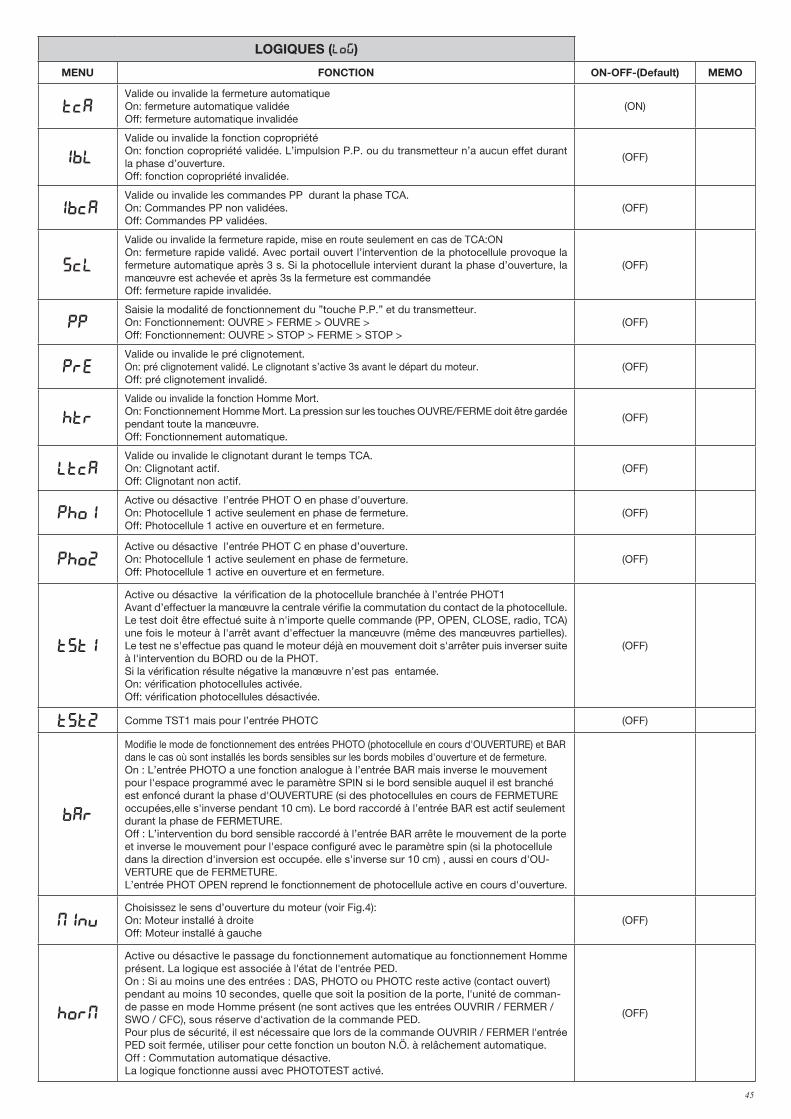
45
LOGIQUES (LOG)
MENU FONCTION ON-OFF-(Default) MEMO
TCAValide ou invalide la fermeture automatiqueOn: fermeture automatique validéeOff: fermeture automatique invalidée
(ON)
IBL
Valide ou invalide la fonction copropriétéOn: fonction copropriété validée. L’impulsion P.P. ou du transmetteur n’a aucun effet durant la phase d’ouverture.Off: fonction copropriété invalidée.
(OFF)
IBCAValide ou invalide les commandes PP durant la phase TCA.On: Commandes PP non validées.Off: Commandes PP validées.
(OFF)
SCL
Valide ou invalide la fermeture rapide, mise en route seulement en cas de TCA:ONOn: fermeture rapide validé. Avec portail ouvert l’intervention de la photocellule provoque la fermeture automatique après 3 s. Si la photocellule intervient durant la phase d’ouverture, la manœuvre est achevée et après 3s la fermeture est commandée Off: fermeture rapide invalidée.
(OFF)
PPSaisie la modalité de fonctionnement du ”touche P.P.” et du transmetteur.On: Fonctionnement: OUVRE > FERME > OUVRE >Off: Fonctionnement: OUVRE > STOP > FERME > STOP >
(OFF)
PREValide ou invalide le pré clignotement.On: pré clignotement validé. Le clignotant s’active 3s avant le départ du moteur.Off: pré clignotement invalidé.
(OFF)
HTR
Valide ou invalide la fonction Homme Mort.On: Fonctionnement Homme Mort. La pression sur les touches OUVRE/FERME doit être gardée pendant toute la manœuvre.Off: Fonctionnement automatique.
(OFF)
LTCAValide ou invalide le clignotant durant le temps TCA.On: Clignotant actif.Off: Clignotant non actif.
(OFF)
Pho1Active ou désactive l’entrée PHOT O en phase d’ouverture.On: Photocellule 1 active seulement en phase de fermeture.Off: Photocellule 1 active en ouverture et en fermeture.
(OFF)
Pho2Active ou désactive l’entrée PHOT C en phase d’ouverture.On: Photocellule 1 active seulement en phase de fermeture.Off: Photocellule 1 active en ouverture et en fermeture.
(OFF)
tst1
Active ou désactive la vérification de la photocellule branchée à l’entrée PHOT1Avant d’effectuer la manœuvre la centrale vérifie la commutation du contact de la photocellule. Le test doit être effectué suite à n'importe quelle commande (PP, OPEN, CLOSE, radio, TCA) une fois le moteur à l'arrêt avant d'effectuer la manœuvre (même des manœuvres partielles). Le test ne s'effectue pas quand le moteur déjà en mouvement doit s'arrêter puis inverser suite à l'intervention du BORD ou de la PHOT.Si la vérification résulte négative la manœuvre n’est pas entamée.On: vérification photocellules activée.Off: vérification photocellules désactivée.
(OFF)
tst2 Comme TST1 mais pour l’entrée PHOTC (OFF)
bar
Modifie le mode de fonctionnement des entrées PHOTO (photocellule en cours d'OUVERTURE) et BAR dans le cas où sont installés les bords sensibles sur les bords mobiles d'ouverture et de fermeture.On : L’entrée PHOTO a une fonction analogue à l’entrée BAR mais inverse le mouvement pour l'espace programmé avec le paramètre SPIN si le bord sensible auquel il est branché est enfoncé durant la phase d'OUVERTURE (si des photocellules en cours de FERMETURE occupées,elle s'inverse pendant 10 cm). Le bord raccordé à l’entrée BAR est actif seulement durant la phase de FERMETURE.Off : L’intervention du bord sensible raccordé à l’entrée BAR arrête le mouvement de la porte et inverse le mouvement pour l'espace configuré avec le paramètre spin (si la photocellule dans la direction d'inversion est occupée. elle s'inverse sur 10 cm) , aussi en cours d'OU-VERTURE que de FERMETURE.L’entrée PHOT OPEN reprend le fonctionnement de photocellule active en cours d'ouverture.
MINVChoisissez le sens d’ouverture du moteur (voir Fig.4):On: Moteur installé à droiteOff: Moteur installé à gauche
(OFF)
horm
Active ou désactive le passage du fonctionnement automatique au fonctionnement Homme présent. La logique est associée à l'état de l'entrée PED.On : Si au moins une des entrées : DAS, PHOTO ou PHOTC reste active (contact ouvert) pendant au moins 10 secondes, quelle que soit la position de la porte, l'unité de comman-de passe en mode Homme présent (ne sont actives que les entrées OUVRIR / FERMER / SWO / CFC), sous réserve d'activation de la commande PED. Pour plus de sécurité, il est nécessaire que lors de la commande OUVRIR / FERMER l'entrée PED soit fermée, utiliser pour cette fonction un bouton N.Ö. à relâchement automatique.Off : Commutation automatique désactive.La logique fonctionne aussi avec PHOTOTEST activé.
(OFF)
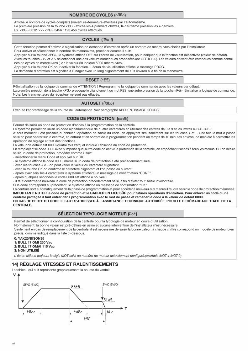
46
NOMBRE DE CYCLES (Nman)
Affiche le nombre de cycles complets (ouverture+fermeture effectués par l’automatisme.La première pression de la touche <PG> affiche les 4 premiers chiffres, la deuxième pression les 4 derniers.Ex. <PG> 0012 >>> <PG> 3456 : 123.456 cycles effectués.
CYCLES (maci)
Cette fonction permet d’activer la signalisation de demande d’entretien après un nombre de manœuvres choisit par l’installateur.Pour activer et sélectionner le nombre de manœuvres, procéder comme il suit:Appuyer sur la touche <PG>, le système affiche OFF sur l’écran de visualisation, pour indiquer que la fonction est désactivée (valeur de défaut). Avec les touches <+> et <-> sélectionner une des valeurs numériques proposées (de OFF à 100). Les valeurs doivent être entendues comme centai-nes de cycles de manœuvres (i.e.: la valeur 50 indique 5000 manœuvres).Appuyer sur la touche OK pour activer la fonction. L’écran de visualisation affiche le message PROG.La demande d’entretien est signalée à l’usager avec un long clignotement de 10s environ à la fin de la manœuvre.
RESET (RES)Réinitialisation de la logique de commande ATTENTION ! Reprogramme la logique de commande avec les valeurs par défaut.La première pression de la touche <PG> provoque le clignotement du mot RES, une autre pression de la touche <PG> réinitialise la logique de commande.Note: Les transmetteurs du récepteur ne sont pas effacés.
AUTOSET (AUTO)
Exécute l’apprentissage de la course de l’automation. Voir paragraphe APPRENTISSAGE COURSE
CODE DE PROTECTION (CODE)Permet de saisir un code de protection d’accès à la programmation de la centrale.Le système permet de saisir un code alphanumérique de quatre caractères en utilisant des chiffres de 0 a 9 et les lettres A-B-C-D-E-F.A’ tout moment il est possible d’ annuler l’opération de saisie du code, en appuyant simultanément sur les touches + et -. Une fois le mot d passe saisi on peut opérer sur la centrale, en entrant et en sortant de la programmation pendant un temps de 10 minutes environ, de manière à permettre les opération de réglage et test des fonctions.La valeur de défaut est 0000 (quatre fois zéro) et indique l’absence du code de protection.En remplaçant le code 0000 avec n’importe quel autre code on active la protection de la centrale, en empêchant l’accès à tous les menus. Si l’on désire saisir un code de protection, procéder comme il suit:- sélectionner le menu Code et appuyer sur OK.- le système affiche le code 0000, même si un code de protection à été précédemment saisi.- avec les touches + e – on peut varier la valeur du caractère clignotant.- avec la touche OK on confirme le caractère clignotant et l’on passe au suivant.- après avoir saisi les 4 caractères le système affichera un message de confirmation “CONF”.- après quelques secondes le code 0000 est affiché à nouveau - il faut confirmer à nouveau le code de protection précédemment saisi, à fin d’éviter tout saisie involontaire.Si le code correspond au précédent, le système affiche un message de confirmation “OK”La centrale sort automatiquement de la phase de programmation et pour accéder à nouveau aux menus il faudra saisir le code de protection mémorisé.IMPORTANT: NOTER le code de protection et le GARDER EN LIEU SÛR pour futures opérations d’entretien. Pour enlever un code d’une centrale protégée il faut entrer dans programmation avec le mot de passe et ramener le code à la valeur de défaut 0000.EN CAS DE PERTE DU CODE IL FAUT S’ADRESSER À L’ASSISTANCE TECHNIQUE AUTORISÉE, POUR LE REDÉMARRAGE TOATL DE LA CENTRALE.
SÉLECTION TYPOLOGIE MOTEUR (mot)
Permet de sélectionner la configuration de la centrale pour la typologie de moteur en cours d'utilisation.Normalement, la bonne valeur est pré-définie en usine et aucune intervention de l'installateur n'est nécessaire.Seulement en cas de remplacement de la centrale, il est nécessaire de saisir la bonne valeur, à chaque chiffre correspond un modèle de moteur bien précis, comme indiqué dans la liste ci-dessous.
0: YAK25/BISON351: BULL 17 OMI 230 Vac2: BULL 17 OMAI 115 Vac3: NON UTILISÉ
L'écran affiche toujours le sigle MOT suivi du numéro de moteur actuellement configuré.(exemple MOT.1,MOT.2)
14) RÈGLAGE VITESSES ET RALENTISSEMENTSLe tableau qui suit représente graphiquement la course du vantail:
V
T
FSTS
slds
BLcTAcc Tdec
TSM
SWO (SWC) SWC (SWO)
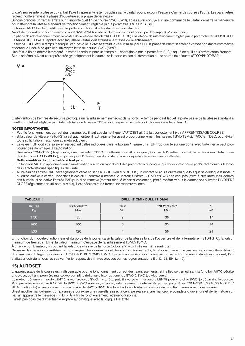
47
L’axe V représente la vitesse du vantail, l’axe T représente le temps utilisé par le vantail pour parcourir l’espace d’un fin de course à l’autre. Les paramètres règlent indifféremment la phase d’ouverture et la phase de fermeture.Si nous prenons un vantail arrêté sur n’importe quel fin de course SWO (SWC), après avoir appuyé sur une commande le vantail démarre la manœuvre pour atteindre la vitesse standard de fonctionnement, réglable par le paramètre FSTSO/FSTSC. Le temps TACC fixe la rapidité avec laquelle le vantail doit atteindre sa vitesse standard.Avant de rencontrer le fin de course d’arrêt SWC (SWO) la phase de ralentissement saisie par le temps TSM commence.La phase de ralentissement mène le vantail de la vitesse standard (FSTSO/FSTSC) à la vitesse de ralentissement réglée par le paramètre SLDSO/SLDSC.Le temps TDEC fixe la rapidité avec laquelle le vantail doit atteindre la vitesse de ralentissement.Le temps TDEC est un temps théorique, car, dès que la vitesse atteint la valeur saisie par SLDS la phase de ralentissement à vitesse constante commence et continue jusqu’à ce qu’elle n’intercepte le fin de course SWC (SWO).Une fois le fin de course intercepté, le vantail continue pour un temps qui est réglable par le paramètre BLC jusqu’à ce qu’il ne s’arrête complètement.Sur le schéma suivant est représentée graphiquement la course de la porte en cas d'intervention d'une entrée de sécurité (STOP/PHOT/BAR) :
V
T
FSTo/fstc
sldo/SldC
BLo/blcTAcc Tdec
TSMo/tsmc
SWO (SWC) SWC (SWO)
V
Ttbr
stopphotbar
L'intervention de l'entrée de sécurité provoque un ralentissement immédiat de la porte, le temps pendant lequel la porte passe de la vitesse standard à l'arrêt complet est réglable par l'intermédiaire de la valeur TBR et doit respecter les valeurs indiquées dans le tableau 1.
NOTES IMPORTANTES:- Pour le fonctionnement correct des paramètres, il faut absolument que l’AUTOSET ait été fait correctement (voir APPRENTISSAGE COURSE).- Si la valeur de vitesse FSTo(FSTc) est augmentée, il faut augmenter aussi proportionnellement les valeurs TSMo(TSMc), TACC et TDEC, pour éviter
toute sollicitation mécanique au motoréducteur.- La valeur TBR doit être saisie en respectant celles indiquées dans le tableau 1, saisie une TBR trop courte sur une porte avec forte inertie peut pro-
voquer des dommages à l'automation. Une valeur TSMo(TSMc) trop courte, avec une valeur TDEC trop élevée pourrait provoquer, à cause de l’inertie du vantail, la remise à zéro de la phase
de ralentissent SLDo(SLDc), en provoquant l’intervention du fin de course lorsque la vitesse est encore élevée. Cette condition doit être évitée à tout prix.- La fonction AUTO n’applique aucune modification aux valeurs de défaut des paramètres ci-dessus, qui doivent être saisis par l’installateur sur la base
des caractéristiques spécifiques du vantail.- Au niveau de l'entrée BAR, sera également câblé en série au BORD (ou aux BORDS) un contact NC qui s'ouvre chaque fois que se débloque le moteur
ou qu'on enlève le carter. Donc dans le cas où 1. centrale alimentée, 2. Moteur à l'arrêt, 3. SWO et SWC non occupés (c'est-à-dire moteur en-dehors des butées), si on active l'entrée BAR puis si on réactive (moteur bloqué et carter enclenché, prêt à redémarrer), à la commande suivante PP/OPEN/CLOSE (également en utilisant la radio), il est nécessaire de forcer une manœuvre lente.
TABLEAU 1 BULL 17 OMI / BULL 17 OMAI
POIDSKg
FSTO/FSTCMax
TBRMin
TSMO/TSMCMin
Vm/1'
1700 85 2 30 17
1000 100 3 35 20
500 120 4 50 24
En fonction du modèle d'actionneur et du poids de la porte, saisir la valeur de la vitesse lors de l'ouverture et de la fermeture (FSTO/FSTC), la valeur minimum de freinage TBR et la valeur minimum d'espace de ralentissement TSMO/TSMC.À chaque combinaison, on obtient la valeur de vitesse de la porte (colonne V) exprimée en mètres/minute.Dépasser les valeurs conseillées peut provoquer des dommages et des dysfonctionnements, le fabricant n'assume pas les responsabilités dérivant d'un mauvais réglage des valeurs FSTO/FSTC/TBR/TSMO/TSMC. Les valeurs saisies sont indicatives et se réfèrent à une installation standard, l'in-stallateur doit dans tous les cas vérifier le respect des limites prévues par les réglementations EN 12453, EN 12445).
15) AUTOSETL’apprentissage de la course est indispensable pour le fonctionnement correct des ralentissements, et il a lieu soit en utilisant la fonction AUTO décrite ci-dessus, soit à la première manœuvre complète (faite sans interruptions) de SWO à SWC (ou vice-versa).Le moteur démarre en mode LENT à la recherche de SWO, il s'arrête, puis il inverse en manœuvre LENTE pour chercher SWC (je détermine la course). Puis première manœuvre RAPIDE de SWC à SWO (rampes, vitesses, ralentissements déterminés par les paramètres TSMo/TSMc/FSTo/FSTc/SLDo/SLDc configurés) et seconde manœuvre rapide de SWO à SWC. Par la suite il sera toutefois possible de modifier manuellement ces valeurs.Si est modifié manuellement un paramètre qui exige une nouvelle saisie, la centrale réalisera une manœuvre complète d'ouverture et de fermeture sur l'écran apparaitra le message « PRG ». À la fin, le fonctionnement redeviendra normal.Il n'est pas possible d'effectuer le réglage automatique avec la logique HTR:ON
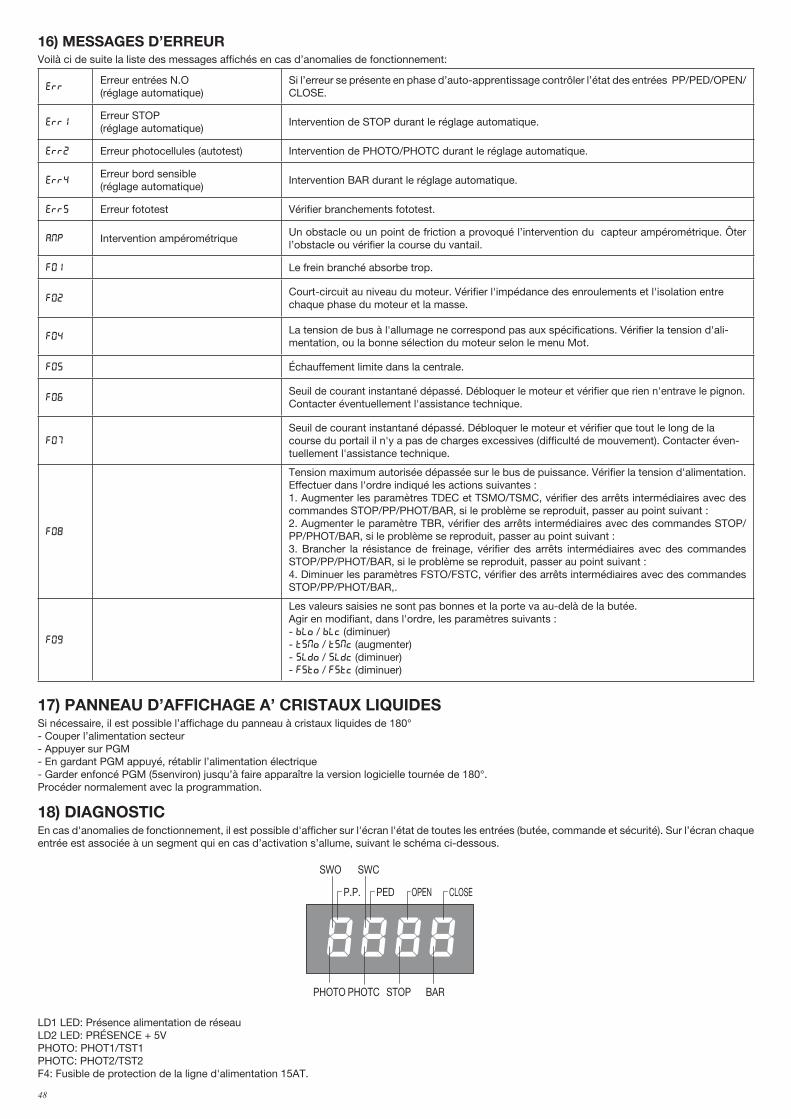
48
16) MESSAGES D’ERREURVoilà ci de suite la liste des messages affichés en cas d’anomalies de fonctionnement:
errErreur entrées N.O (réglage automatique)
Si l’erreur se présente en phase d’auto-apprentissage contrôler l’état des entrées PP/PED/OPEN/CLOSE.
Err1Erreur STOP (réglage automatique)
Intervention de STOP durant le réglage automatique.
Err2 Erreur photocellules (autotest) Intervention de PHOTO/PHOTC durant le réglage automatique.
Err4Erreur bord sensible (réglage automatique)
Intervention BAR durant le réglage automatique.
Err5 Erreur fototest Vérifier branchements fototest.
amp Intervention ampérométrique Un obstacle ou un point de friction a provoqué l’intervention du capteur ampérométrique. Ôter l’obstacle ou vérifier la course du vantail.
f01 Le frein branché absorbe trop.
F02Court-circuit au niveau du moteur. Vérifier l'impédance des enroulements et l'isolation entre chaque phase du moteur et la masse.
F04La tension de bus à l'allumage ne correspond pas aux spécifications. Vérifier la tension d'ali-mentation, ou la bonne sélection du moteur selon le menu Mot.
F05 Échauffement limite dans la centrale.
F06Seuil de courant instantané dépassé. Débloquer le moteur et vérifier que rien n'entrave le pignon. Contacter éventuellement l'assistance technique.
F07
Seuil de courant instantané dépassé. Débloquer le moteur et vérifier que tout le long de la course du portail il n'y a pas de charges excessives (difficulté de mouvement). Contacter éven-tuellement l'assistance technique.
F08
Tension maximum autorisée dépassée sur le bus de puissance. Vérifier la tension d'alimentation. Effectuer dans l'ordre indiqué les actions suivantes :1. Augmenter les paramètres TDEC et TSMO/TSMC, vérifier des arrêts intermédiaires avec des commandes STOP/PP/PHOT/BAR, si le problème se reproduit, passer au point suivant :2. Augmenter le paramètre TBR, vérifier des arrêts intermédiaires avec des commandes STOP/PP/PHOT/BAR, si le problème se reproduit, passer au point suivant :3. Brancher la résistance de freinage, vérifier des arrêts intermédiaires avec des commandes STOP/PP/PHOT/BAR, si le problème se reproduit, passer au point suivant :4. Diminuer les paramètres FSTO/FSTC, vérifier des arrêts intermédiaires avec des commandes STOP/PP/PHOT/BAR,.
F09
Les valeurs saisies ne sont pas bonnes et la porte va au-delà de la butée.Agir en modifiant, dans l'ordre, les paramètres suivants :- blo / blc (diminuer)- tsmo / tsmc (augmenter)- sldo / sldc (diminuer)- fsto / fstc (diminuer)
17) PANNEAU D’AFFICHAGE A’ CRISTAUX LIQUIDESSi nécessaire, il est possible l’affichage du panneau à cristaux liquides de 180° - Couper l’alimentation secteur- Appuyer sur PGM- En gardant PGM appuyé, rétablir l’alimentation électrique- Garder enfoncé PGM (5senviron) jusqu’à faire apparaître la version logicielle tournée de 180°. Procéder normalement avec la programmation.
18) DIAGNOSTICEn cas d'anomalies de fonctionnement, il est possible d'afficher sur l'écran l'état de toutes les entrées (butée, commande et sécurité). Sur l’écran chaque entrée est associée à un segment qui en cas d’activation s’allume, suivant le schéma ci-dessous.
PHOTO
SWC
STOP
SWO
PHOTC BAR
P.P. PED OPEN CLOSE
LD1 LED: Présence alimentation de réseauLD2 LED: PRÉSENCE + 5VPHOTO: PHOT1/TST1PHOTC: PHOT2/TST2F4: Fusible de protection de la ligne d'alimentation 15AT.

49
19) MAINTENANCELe tableau suivant sert à enregistrer les interventions de maintenance, d'amélioration ou de réparation effectuées par le technicien spécialisé.
Date _ _ _ _ _ _ _ _ _ _ _ _ _ _ _ _ _ _ _ _ _ _ _ _ _ _ _ _ _ _ _ _ _ Signature du technicien _ _ _ _ _ _ _ _ _ _ _ _ _ _ _ _ _ _ _ _ _ _ Tampon
Description de l'intervention
_ _ _ _ _ _ _ _ _ _ _ _ _ _ _ _ _ _ _ _ _ _ _ _ _ _ _ _ _ _ _ _ _ _ _ _ _ _ _ _ _ _ _ _ _ _ _ _ _ _ _ _ _ _ _ _ _ _ _ _ _ _ _ _ _ _ _ _ _ _ _ _ _
_ _ _ _ _ _ _ _ _ _ _ _ _ _ _ _ _ _ _ _ _ _ _ _ _ _ _ _ _ _ _ _ _ _ _ _ _ _ _ _ _ _ _ _ _ _ _ _ _ _ _ _ _ _ _ _ _ _ _ _ _ _ _ _ _ _ _ _ _ _ _ _ _
50
ESP ADVERTENCIASINFORMACIÓN GENERAL Está prohibido utilizar el producto para finalidades o con modalidades no previstas en el presente manual. Usos incorrectos pueden causar daños al producto y poner en peligro personas y cosas.Se rehúsa cualquier responsabilidad en caso de incumplimiento de la buena técnica en la construcción de las cancelas, así como en cuanto a las deformaciones que pudieran producirse durante el uso. Guardar este manual para futuras consultas.
GUÍA DEL INSTALADOR Este manual está destinado exclusivamente a personal cualificado para la instalación y el mantenimiento de aperturas automáticas.La instalación debe ser realizada por personal cualificado (instalador profesional, conforme a EN12635), en cumplimiento del la Buena Técnica y de las normas vigentes. Controle que la estructura de la puerta sea adecuada para su automatización. El instalador debe propor-cionar todas las informaciones relativas al funcionamiento automático, manual y de emergencia de la automatización y entregar al usuario del equipo las instrucciones de uso.
ADVERTENCIAS GENERALES Los elementos del embalaje no se deben dejar al alcance de los niños ya que son potenciales fuentes de peligro. No tirar al medio ambiente los elementos del embalaje, sino que se deben separar según los varios tipos (por ej. cartón, poliestireno) y evacuarlos de conformidad con las normas locales. No permitir que los niños jueguen con los dispositivos de mando del producto. Mantener los mandos a distancia fueradel alcance de los niños. Este producto no está destinado al uso por parte de niños ni de personas con capacidades físicas, sensoriales o mentales reducidas, o carentes de los conocimientos necesarios, salvo bajo las instrucciones y la vigilancia de una persona que se haga responsable de su seguridad. Aplicar todos los dispositivos de seguridad (fotocélulas, cantos sensibles, etc.) necesarios para proteger el área de peligros de impacto, aplastamiento, arrastre, corte. Tener en cuenta las normativas y nlas directivas vigentes, los criterios de la Buena Técnica, el uso, el entorno de instalación, la lógica de funcionamiento del sistema y las fuerzas desarrolladas por la automatización. La instalación se debe realizar utilizando dispositivos de seguridad y de mandos conformes a la EN 12978 y EN12453. Usar exclusivamente accesorios y repuestos originales, el uso de componentes no originales implica la exclusión del producto de las coberturas previstas por el certificado de Garantía. Todas las partes, mecánicas y eléctricas, que componen la automatización deben cumplir con los requisitos de las normativas vigentes y que se muestran en la marca CE.
SEGURIDAD ELECTRICAPrever en la red de alimentación un interruptor/cortacircuitos omnipolar con distancia de apertura de los contactos igual o mayor que 3 mm.Comprobar que entre el aparato y la red eléctrica general haya un interruptor diferencial y una protección contra sobrecorriente adecuados. Algunos tipos de instalación requieren que se conecte la hoja con una instalación de puesta a tierra conforme a las vigentes normas de se-guridad. Durante las operaciones de instalación, mantenimiento y reparación, cortar la alimentación antes de acceder a las partes eléctricas.Desconectar tambiEn eventuales baterías compensadoras si estuvieran presentes. La instalación eléctrica y la lógica de funcionamiento deben cumplir las normas vigentes. Los conductores alimentados con tensiones distintas deben estar físicamente separados, o bien deben estar adecuadamente aislados con aislamiento suplementario de por lo menos 1 mm. Los conductores deben estar vinculados por una fijación suplementaria cerca de los bornes. Durante las operaciones de instalación, mantenimiento y reparación, cortar la alimentación antes de acceder a las partes eléctricas. Comprobar todas las conexiones efectuadas antes de dar la tensión. Las entradas N.C. no utilizadas deben estar puenteadas.
ELIMINACIÓNComo indicado por el símbolo de al lado, está prohibido tirar este producto a la basura doméstica ya que algunas partes que lo componen podrías ser nocivas para el medio ambiente y la salud human si se eliminan de manera errada. Por lo tanto el aparato se deberá entregar a idóneos centro de recogida selectiva o bien se deberá devolver al revendedor en el momento de comprar un nuevo aparato equivalente. La eliminación ilegal del producto por parte del usuario conlleva la aplicación de las sanciones administrativas previstas por las normas vigentes.
Las descripciones y las ilustraciones presentadas en este manual no son vinculantes. Sin cambiar las características esenciales del producto, el fabricante se reserva el derecho de aportar cualquier modificación de carácter técnico, constructivo o comercial sin obligación de actualizar la presente publicación.
¡ATENCIÓN!La central utiliza condensadores de alta capacidad que pueden ser peligrosos, incluso si falta alimenta-ción de red. Antes de acceder a la central, es indispensable aguar-dar 60 segundos, como mínimo, después de haber desconectado la alimentación de red.
Read Instructions
DO NOT TOUCH!DISCONNECT M A I N S U P P LY WAIT!
60 sec.
WARNING!
F8369256
Etichetta WARNING: Formato 55x50mm
stampa su PVC adesivo4 colori
Read Instructions
DO NOT TOUCH!DISCONNECT M A I N S U P P LY WAIT!
60 sec.
WARNING!
F8369256
Etichetta WARNING: Formato 55x50mm
stampa su PVC adesivo4 colori
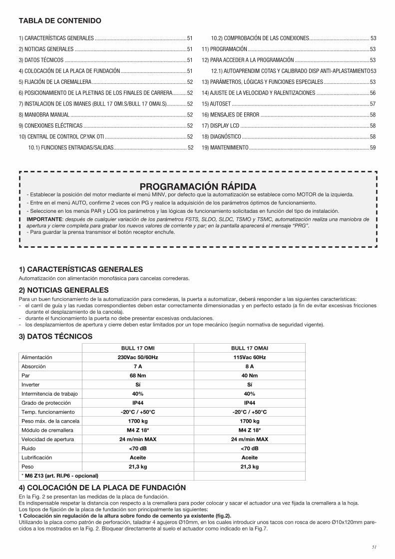
51
1) CARACTERÍSTICAS GENERALESAutomatización con alimentación monofásica para cancelas correderas.
2) NOTICIAS GENERALESPara un buen funcionamiento de la automatización para correderas, la puerta a automatizar, deberá responder a las siguientes características:- el carril de guía y las ruedas correspondientes deben estar correctamente dimensionadas y en perfecto estado (a fin de evitar excesivas fricciones
durante el desplazamiento de la cancela).- durante el funcionamiento la puerta no debe presentar excesivas ondulaciones.- los desplazamientos de apertura y cierre deben estar limitados por un tope mecánico (según normativa de seguridad vigente).
3) DATOS TÉCNICOS
BULL 17 OMI BULL 17 OMAI
Alimentación 230Vac 50/60Hz 115Vac 60Hz
Absorción 7 A 8 A
Par 68 Nm 40 Nm
Inverter Sí Sí
Intermitencia de trabajo 40% 40%
Grado de protección IP44 IP44
Temp. funcionamiento -20°C / +50°C -20°C / +50°C
Peso máx. de la cancela 1700 kg 1700 kg
Módulo de cremallera M4 Z 18* M4 Z 18*
Velocidad de apertura 24 m/min MAX 24 m/min MAX
Ruido <70 dB <70 dB
Lubrificación Aceite Aceite
Peso 21,3 kg 21,3 kg
* M6 Z13 (art. RI.P6 - opcional)
4) COLOCACIÓN DE LA PLACA DE FUNDACIÓNEn la Fig. 2 se presentan las medidas de la placa de fundación.Es indispensable respetar la distancia con respecto a la cremallera para poder colocar y sacar el actuador una vez fijada la cremallera a la hoja.Los tipos de fijación de la placa de fundación son principalmente las siguientes:1 Colocación sin regulación de la altura sobre fondo de cemento ya existente (fig.2). Utilizando la placa como patrón de perforación, taladrar 4 agujeros Ø10mm, en los cuales introducir unos tacos con rosca de acero Ø10x120mm pare-cidos a los mostrados en la Fig. 2. Bloquear directamente al suelo el actuador como indicado en la Fig.7.
1) CARACTERÍSTICAS GENERALES ................................................................51
2) NOTICIAS GENERALES ..............................................................................51
3) DATOS TÉCNICOS .....................................................................................51
4) COLOCACIÓN DE LA PLACA DE FUNDACIÓN ..............................................51
5) FIJACIÓN DE LA CREMALLERA ..................................................................52
6) POSICIONAMIENTO DE LA PLETINAS DE LOS FINALES DE CARRERA ..........52
7) INSTALACION DE LOS IMANES (BULL 17 OMI.S/BULL 17 OMAI.S) ..............52
8) MANIOBRA MANUAL .................................................................................52
9) CONEXIONES ELÉCTRICAS ........................................................................52
10) CENTRAL DE CONTROL CP.YAK OTI .........................................................52
10.1) FUNCIONES ENTRADAS/SALIDAS ................................................... 52
10.2) COMPROBACIÓN DE LAS CONEXIONES .......................................... 53
11) PROGRAMACIÓN .....................................................................................53
12) PARA ACCEDER A LA PROGRAMACIÓN ....................................................53
12.1) AUTOAPRENDIM COTAS Y CALIBRADO DISP ANTI-APLASTAMIENTO 53
13) PARÁMETROS, LÓGICAS Y FUNCIONES ESPECIALES ................................53
14) AJUSTE DE LA VELOCIDAD Y RALENTIZACIONES .....................................56
15) AUTOSET ................................................................................................57
16) MENSAJES DE ERROR ............................................................................58
17) DISPLAY LCD ..........................................................................................58
18) DIAGNÓSTICO .........................................................................................58
19) MANTENIMIENTO ....................................................................................59
TABLA DE CONTENIDO
PROGRAMACIÓN RÁPIDA- Establecer la posición del motor mediante el menú MINV, por defecto que la automatización se establece como MOTOR de la izquierda.
- Entre en el menú AUTO, confirme 2 veces con PG y realice la adquisición de los parámetros óptimos de funcionamiento.
- Seleccione en los menús PAR y LOG los parámetros y las lógicas de funcionamiento solicitadas en función del tipo de instalación.
IMPORTANTE: después de cualquier variación de los parámetros FSTS, SLDO, SLDC, TSMO y TSMC, automatización realiza una maniobra de apertura y cierre completa para grabar los nuevos valores de corriente y par; en la pantalla aparecerá el mensaje “PRG”.- Para guardar la prensa transmisor el botón receptor enchufe.
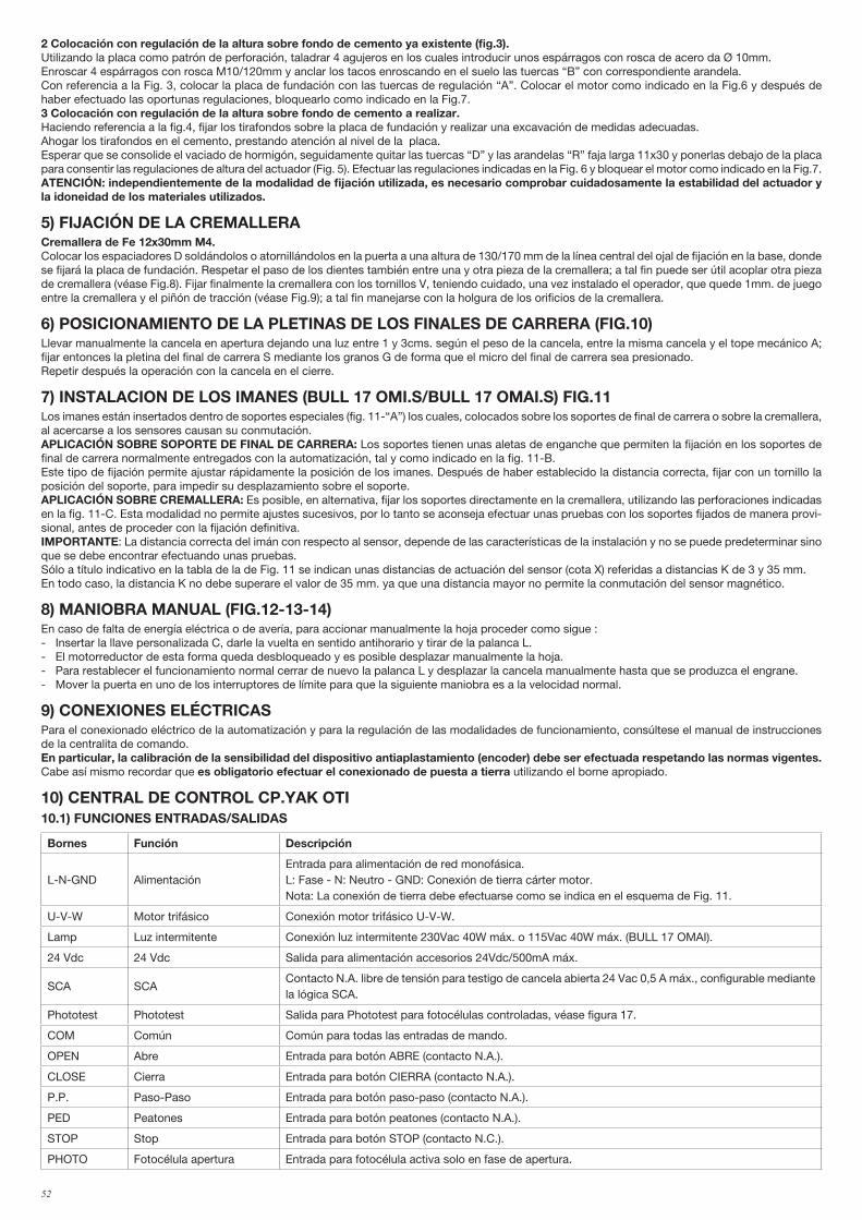
52
2 Colocación con regulación de la altura sobre fondo de cemento ya existente (fig.3). Utilizando la placa como patrón de perforación, taladrar 4 agujeros en los cuales introducir unos espárragos con rosca de acero da Ø 10mm.Enroscar 4 espárragos con rosca M10/120mm y anclar los tacos enroscando en el suelo las tuercas “B” con correspondiente arandela.Con referencia a la Fig. 3, colocar la placa de fundación con las tuercas de regulación “A”. Colocar el motor como indicado en la Fig.6 y después de haber efectuado las oportunas regulaciones, bloquearlo como indicado en la Fig.7.3 Colocación con regulación de la altura sobre fondo de cemento a realizar. Haciendo referencia a la fig.4, fijar los tirafondos sobre la placa de fundación y realizar una excavación de medidas adecuadas.Ahogar los tirafondos en el cemento, prestando atención al nivel de la placa. Esperar que se consolide el vaciado de hormigón, seguidamente quitar las tuercas “D” y las arandelas “R” faja larga 11x30 y ponerlas debajo de la placa para consentir las regulaciones de altura del actuador (Fig. 5). Efectuar las regulaciones indicadas en la Fig. 6 y bloquear el motor como indicado en la Fig.7.ATENCIÓN: independientemente de la modalidad de fijación utilizada, es necesario comprobar cuidadosamente la estabilidad del actuador y la idoneidad de los materiales utilizados.
5) FIJACIÓN DE LA CREMALLERACremallera de Fe 12x30mm M4.Colocar los espaciadores D soldándolos o atornillándolos en la puerta a una altura de 130/170 mm de la línea central del ojal de fijación en la base, donde se fijará la placa de fundación. Respetar el paso de los dientes también entre una y otra pieza de la cremallera; a tal fin puede ser útil acoplar otra pieza de cremallera (véase Fig.8). Fijar finalmente la cremallera con los tornillos V, teniendo cuidado, una vez instalado el operador, que quede 1mm. de juego entre la cremallera y el piñón de tracción (véase Fig.9); a tal fin manejarse con la holgura de los orificios de la cremallera.
6) POSICIONAMIENTO DE LA PLETINAS DE LOS FINALES DE CARRERA (FIG.10)Llevar manualmente la cancela en apertura dejando una luz entre 1 y 3cms. según el peso de la cancela, entre la misma cancela y el tope mecánico A; fijar entonces la pletina del final de carrera S mediante los granos G de forma que el micro del final de carrera sea presionado. Repetir después la operación con la cancela en el cierre.
7) INSTALACION DE LOS IMANES (BULL 17 OMI.S/BULL 17 OMAI.S) FIG.11Los imanes están insertados dentro de soportes especiales (fig. 11-“A”) los cuales, colocados sobre los soportes de final de carrera o sobre la cremallera, al acercarse a los sensores causan su conmutación.APLICACIÓN SOBRE SOPORTE DE FINAL DE CARRERA: Los soportes tienen unas aletas de enganche que permiten la fijación en los soportes de final de carrera normalmente entregados con la automatización, tal y como indicado en la fig. 11-B.Este tipo de fijación permite ajustar rápidamente la posición de los imanes. Después de haber establecido la distancia correcta, fijar con un tornillo la posición del soporte, para impedir su desplazamiento sobre el soporte.APLICACIÓN SOBRE CREMALLERA: Es posible, en alternativa, fijar los soportes directamente en la cremallera, utilizando las perforaciones indicadas en la fig. 11-C. Esta modalidad no permite ajustes sucesivos, por lo tanto se aconseja efectuar unas pruebas con los soportes fijados de manera provi-sional, antes de proceder con la fijación definitiva.IMPORTANTE: La distancia correcta del imán con respecto al sensor, depende de las características de la instalación y no se puede predeterminar sino que se debe encontrar efectuando unas pruebas.Sólo a título indicativo en la tabla de la de Fig. 11 se indican unas distancias de actuación del sensor (cota X) referidas a distancias K de 3 y 35 mm.En todo caso, la distancia K no debe superare el valor de 35 mm. ya que una distancia mayor no permite la conmutación del sensor magnético.
8) MANIOBRA MANUAL (FIG.12-13-14)En caso de falta de energía eléctrica o de avería, para accionar manualmente la hoja proceder como sigue : - Insertar la llave personalizada C, darle la vuelta en sentido antihorario y tirar de la palanca L.- El motorreductor de esta forma queda desbloqueado y es posible desplazar manualmente la hoja.- Para restablecer el funcionamiento normal cerrar de nuevo la palanca L y desplazar la cancela manualmente hasta que se produzca el engrane.- Mover la puerta en uno de los interruptores de límite para que la siguiente maniobra es a la velocidad normal.
9) CONEXIONES ELÉCTRICASPara el conexionado eléctrico de la automatización y para la regulación de las modalidades de funcionamiento, consúltese el manual de instrucciones de la centralita de comando.En particular, la calibración de la sensibilidad del dispositivo antiaplastamiento (encoder) debe ser efectuada respetando las normas vigentes.Cabe así mismo recordar que es obligatorio efectuar el conexionado de puesta a tierra utilizando el borne apropiado.
10) CENTRAL DE CONTROL CP.YAK OTI10.1) FUNCIONES ENTRADAS/SALIDAS
Bornes Función Descripción
L-N-GND AlimentaciónEntrada para alimentación de red monofásica.L: Fase - N: Neutro - GND: Conexión de tierra cárter motor.Nota: La conexión de tierra debe efectuarse como se indica en el esquema de Fig. 11.
U-V-W Motor trifásico Conexión motor trifásico U-V-W.
Lamp Luz intermitente Conexión luz intermitente 230Vac 40W máx. o 115Vac 40W máx. (BULL 17 OMAI).
24 Vdc 24 Vdc Salida para alimentación accesorios 24Vdc/500mA máx.
SCA SCAContacto N.A. libre de tensión para testigo de cancela abierta 24 Vac 0,5 A máx., configurable mediante la lógica SCA.
Phototest Phototest Salida para Phototest para fotocélulas controladas, véase figura 17.
COM Común Común para todas las entradas de mando.
OPEN Abre Entrada para botón ABRE (contacto N.A.).
CLOSE Cierra Entrada para botón CIERRA (contacto N.A.).
P.P. Paso-Paso Entrada para botón paso-paso (contacto N.A.).
PED Peatones Entrada para botón peatones (contacto N.A.).
STOP Stop Entrada para botón STOP (contacto N.C.).
PHOTO Fotocélula apertura Entrada para fotocélula activa solo en fase de apertura.
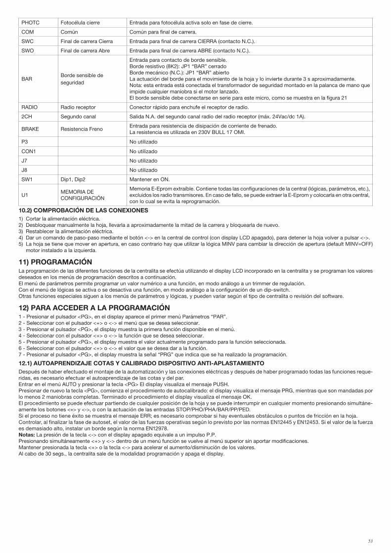
53
PHOTC Fotocélula cierre Entrada para fotocélula activa solo en fase de cierre.
COM Común Común para final de carrera.
SWC Final de carrera Cierra Entrada para final de carrera CIERRA (contacto N.C.).
SWO Final de carrera Abre Entrada para final de carrera ABRE (contacto N.C.).
BARBorde sensible deseguridad
Entrada para contacto de borde sensible.Borde resistivo (8K2): JP1 “BAR” cerradoBorde mecánico (N.C.): JP1 “BAR” abiertoLa actuación del borde para el movimiento de la hoja y lo invierte durante 3 s aproximadamente.Nota: esta entrada está conectada el transformador de seguridad montado en la palanca de mano que impide cualquier maniobra si el motor lanzado.El borde sensible debe conectarse en serie para este micro, como se muestra en la figura 21
RADIO Radio receptor Conector rápido para enchufe el receptor de radio.
2CH Segundo canal Salida N.A. del segundo canal radio del radio receptor (máx. 24Vac/dc 1A).
BRAKE Resistencia FrenoEntrada para resistencia de disipación de corriente de frenado.La resistencia es utilizada en 230V BULL 17 OMI.
P3 No utilizado
CON1 No utilizado
J7 No utilizado
J8 No utilizado
SW1 Dip1, Dip2 Mantener en ON.
U1MEMORIA DE CONFIGURACIÓN
Memoria E-Eprom extraíble. Contiene todas las configuraciones de la central (lógicas, parámetros, etc.), excluidos los radio transmisores. En caso de fallo, se puede extraer la E-Eprom y colocarla en otra central, con lo cual se evita la reprogramación.
10.2) COMPROBACIÓN DE LAS CONEXIONES1) Cortar la alimentación eléctrica.2) Desbloquear manualmente la hoja, llevarla a aproximadamente la mitad de la carrera y bloquearla de nuevo.3) Restablecer la alimentación eléctrica.4) Dar un comando de paso-paso mediante el botón <-> en la central de control (con display LCD apagado), para detener la hoja volver a pulsar <->.5) La hoja se tiene que mover en apertura, en caso contrario hay que utilizar la lógica MINV para cambiar la dirección de apertura (default MINV=OFF)
motor instalado a la izquierda.
11) PROGRAMACIÓNLa programación de las diferentes funciones de la centralita se efectúa utilizando el display LCD incorporado en la centralita y se programan los valores deseados en los menús de programación descritos a continuación. El menú de parámetros permite programar un valor numérico a una función, en modo análogo a un trimmer de regulación.Con el menú de lógicas se activa o se desactiva una función, en modo análogo a la configuración de un dip-switch.Otras funciones especiales siguen a los menús de parámetros y lógicas, y pueden variar según el tipo de centralita o revisión del software.
12) PARA ACCEDER A LA PROGRAMACIÓN1 - Presionar el pulsador <PG>, en el display aparece el primer menú Parámetros “PAR”. 2 - Seleccionar con el pulsador <+> o <-> el menú que se desea seleccionar.3 - Presionar el pulsador <PG>, el display muestra la primera función disponible en el menú.4 - Seleccionar con el pulsador <+> o <-> la función que se desea seleccionar.5 - Presionar el pulsador <PG>, el display muestra el valor actualmente programado para la función seleccionada.6 - Seleccionar con el pulsador <+> o <-> el valor que se desea dar a la función.7 - Presionar el pulsador <PG>, el display muestra la señal “PRG” que indica que se ha realizado la programación.
12.1) AUTOAPRENDIZAJE COTAS Y CALIBRADO DISPOSITIVO ANTI-APLASTAMIENTODespués de haber efectuado el montaje de la automatización y las conexiones eléctricas y después de haber programado todas las funciones reque-ridas, es necesario efectuar el autoaprendizaje de las cotas y del par.Entrar en el menú AUTO y presionar la tecla <PG> El display visualiza el mensaje PUSH.Presionar de nuevo la tecla <PG>, comienza el procedimiento de autocalibrado: el display visualiza el mensaje PRG, mientras que son mandadas por lo menos 2 maniobras completas. Terminado el procedimiento el display visualiza el mensaje OK.El procedimiento se puede efectuar partiendo de cualquier posición de la hoja y se puede interrumpir en cualquier momento presionando simultáne-amente los botones <+> y <->, o con la actuación de las entradas STOP/PHO/PHA/BAR/PP/PED.Si el proceso no tiene éxito se muestra el mensaje ERR; es necesario comprobar si hay eventuales obstáculos o puntos de fricción en la hoja.Controlar, al finalizar la fase de autoset, el valor de las fuerzas operativas según lo previsto por las normas EN12445 y EN12453. Si el valor de la fuerza es demasiado alto, instalar un borde según la norma EN12978.Notas: La presión de la tecla <-> con el display apagado equivale a un impulso P.P.Presionando simultáneamente <+> y <-> dentro de un menú función se vuelve al menú superior sin aportar modificaciones. Mantener presionada la tecla <+> o la tecla <-> para acelerar el aumento/disminución de los valores.Al cabo de 30 segs., la centralita sale de la modalidad programación y apaga el display.
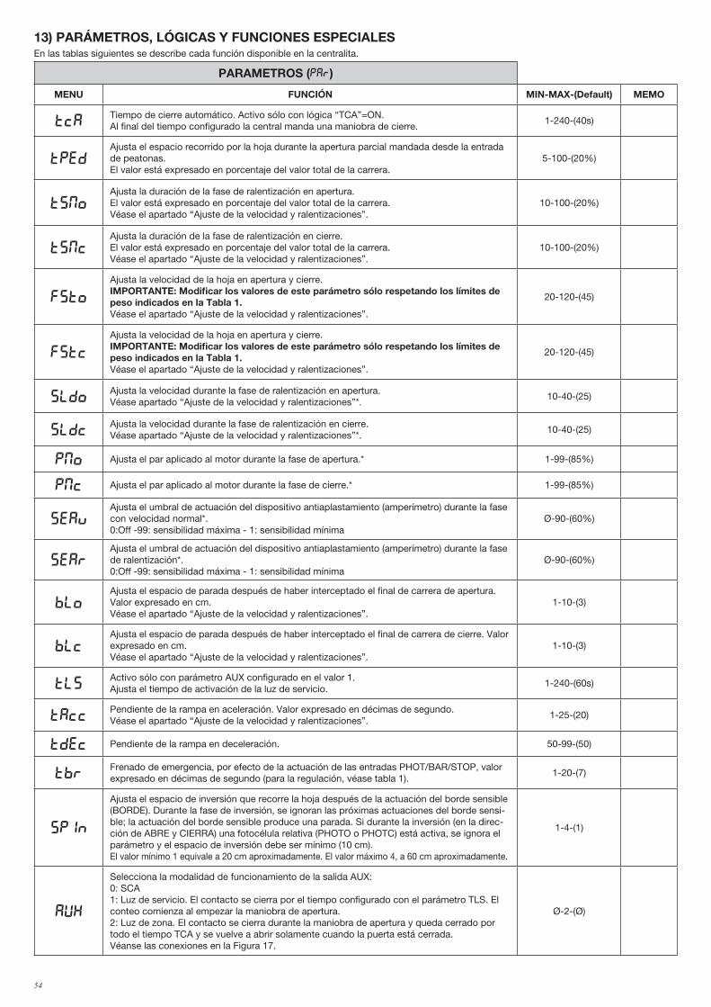
54
13) PARÁMETROS, LÓGICAS Y FUNCIONES ESPECIALESEn las tablas siguientes se describe cada función disponible en la centralita.
PARAMETROS (PAR)
MENU FUNCIÓN MIN-MAX-(Default) MEMO
TCATiempo de cierre automático. Activo sólo con lógica “TCA”=ON.Al final del tiempo configurado la central manda una maniobra de cierre.
1-240-(40s)
TpedAjusta el espacio recorrido por la hoja durante la apertura parcial mandada desde la entrada de peatonas. El valor está expresado en porcentaje del valor total de la carrera.
5-100-(20%)
tsmoAjusta la duración de la fase de ralentización en apertura. El valor está expresado en porcentaje del valor total de la carrera.Véase el apartado “Ajuste de la velocidad y ralentizaciones”.
10-100-(20%)
TsMcAjusta la duración de la fase de ralentización en cierre.El valor está expresado en porcentaje del valor total de la carrera.Véase el apartado “Ajuste de la velocidad y ralentizaciones”.
10-100-(20%)
FSTo
Ajusta la velocidad de la hoja en apertura y cierre.IMPORTANTE: Modificar los valores de este parámetro sólo respetando los límites de peso indicados en la Tabla 1.Véase el apartado “Ajuste de la velocidad y ralentizaciones”.
20-120-(45)
fstc
Ajusta la velocidad de la hoja en apertura y cierre.IMPORTANTE: Modificar los valores de este parámetro sólo respetando los límites de peso indicados en la Tabla 1.Véase el apartado “Ajuste de la velocidad y ralentizaciones”.
20-120-(45)
sldoAjusta la velocidad durante la fase de ralentización en apertura.Véase apartado “Ajuste de la velocidad y ralentizaciones”*.
10-40-(25)
sldcAjusta la velocidad durante la fase de ralentización en cierre.Véase apartado “Ajuste de la velocidad y ralentizaciones”*.
10-40-(25)
PMO Ajusta el par aplicado al motor durante la fase de apertura.* 1-99-(85%)
PMC Ajusta el par aplicado al motor durante la fase de cierre.* 1-99-(85%)
sEavAjusta el umbral de actuación del dispositivo antiaplastamiento (amperímetro) durante la fase con velocidad normal*. 0:Off -99: sensibilidad máxima - 1: sensibilidad mínima
Ø-90-(60%)
sEarAjusta el umbral de actuación del dispositivo antiaplastamiento (amperímetro) durante la fase de ralentización*.0:Off -99: sensibilidad máxima - 1: sensibilidad mínima
Ø-90-(60%)
bloAjusta el espacio de parada después de haber interceptado el final de carrera de apertura. Valor expresado en cm. Véase el apartado “Ajuste de la velocidad y ralentizaciones”.
1-10-(3)
blcAjusta el espacio de parada después de haber interceptado el final de carrera de cierre. Valor expresado en cm. Véase el apartado “Ajuste de la velocidad y ralentizaciones”.
1-10-(3)
TLSActivo sólo con parámetro AUX configurado en el valor 1. Ajusta el tiempo de activación de la luz de servicio.
1-240-(60s)
TACCPendiente de la rampa en aceleración. Valor expresado en décimas de segundo.Véase el apartado “Ajuste de la velocidad y ralentizaciones”.
1-25-(20)
TDEC Pendiente de la rampa en deceleración. 50-99-(50)
TbrFrenado de emergencia, por efecto de la actuación de las entradas PHOT/BAR/STOP, valor expresado en décimas de segundo (para la regulación, véase tabla 1).
1-20-(7)
spin
Ajusta el espacio de inversión que recorre la hoja después de la actuación del borde sensible (BORDE). Durante la fase de inversión, se ignoran las próximas actuaciones del borde sensi-ble; la actuación del borde sensible produce una parada. Si durante la inversión (en la direc-ción de ABRE y CIERRA) una fotocélula relativa (PHOTO o PHOTC) está activa, se ignora el parámetro y el espacio de inversión debe ser mínimo (10 cm).El valor mínimo 1 equivale a 20 cm aproximadamente. El valor máximo 4, a 60 cm aproximadamente.
1-4-(1)
AUX
Selecciona la modalidad de funcionamiento de la salida AUX:0: SCA1: Luz de servicio. El contacto se cierra por el tiempo configurado con el parámetro TLS. El conteo comienza al empezar la maniobra de apertura.2: Luz de zona. El contacto se cierra durante la maniobra de apertura y queda cerrado por todo el tiempo TCA y se vuelve a abrir solamente cuando la puerta está cerrada.Véanse las conexiones en la Figura 17.
Ø-2-(Ø)
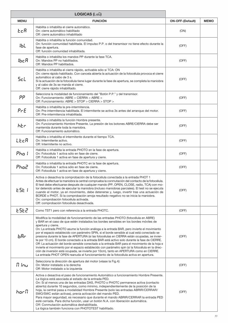
55
LOGICAS (LOG)
MENU FUNCIÓN ON-OFF-(Default) MEMO
TCAHabilita o inhabilita el cierre automático.On: cierre automático habilitadoOff: cierre automático inhabilitado
(ON)
IBL
Habilita o inhabilita la función comunidad.On: función comunidad habilitada. El impulso P.P. o del transmisor no tiene efecto durante la fase de apertura.Off: función comunidad inhabilitada.
(OFF)
IBCAHabilita o inhabilita los mandos PP durante la fase TCA.On: Mandos PP no habilitados.Off: Mandos PP habilitados.
(OFF)
SCL
Habilita o inhabilita el cierre rápido, activable sólo si TCA: ONOn: cierre rápido habilitado. Con cancela abierta la actuación de la fotocélula provoca el cierre automático al cabo de 3 s. Si la actuación de la fotocélula tiene lugar durante la fase de apertura, se completa la maniobra y al cabo de 3s se manda el cierre.Off: cierre rápido inhabilitado.
(OFF)
PPSelecciona la modalidad de funcionamiento del ”Botón P.P.” y del transmisor.On: Funcionamiento: ABRE > CIERRA > ABRE >Off: Funcionamiento: ABRE > STOP > CIERRA > STOP >
(OFF)
PREHabilita o inhabilita la pre-intermitencia.On: Pre-intermitencia habilitada. El intermitente se activa 3s antes del arranque del motor.Off: Pre-intermitencia inhabilitada.
(OFF)
HTR
Habilita o inhabilita la función Hombre presente.On: Funcionamiento Hombre Presente. La presión de los botones ABRE/CIERRA debe ser mantenida durante toda la maniobra.Off: Funcionamiento automático.
(OFF)
LTCAHabilita o inhabilita el intermitente durante el tiempo TCA.On: Intermitente activo.Off: Intermitente no activo.
(OFF)
Pho1Habilita o inhabilita la entrada PHOTO en la fase de apertura.On: Fotocélula 1 activa sólo en fase de cierre.Off: Fotocélula 1 activa en fase de apertura y cierre.
(OFF)
Pho2Habilita o inhabilita la entrada PHOTC en la fase de apertura.On: Fotocélula 1 activa sólo en fase de cierre.Off: Fotocélula 1 activa en fase de apertura y cierre.
(OFF)
tst1
Activa o desactiva la comprobación de la fotocélula conectada a la entrada PHOT 1Antes de efectuar la maniobra la central comprueba la conmutación del contacto de la fotocélula. El test debe efectuarse después de cualquier mando (PP, OPEN, CLOSE, radio, TCA) con mo-tor detenido antes de ejecutar la maniobra (incluso maniobras parciales). El test no se ejecuta cuando el motor, ya en movimiento, debe detenerse y, luego, invertir tras una actuación de BORDE o PHOT. Si la comprobación arroja resultado negativo no se inicia la maniobra.On: comprobación fotocélula activada.Off: comprobación fotocélula desactivada.
(OFF)
tst2 Como TST1 pero con referencia a la entrada PHOTC. (OFF)
bar
Modifica la modalidad de funcionamiento de las entradas PHOTO (fotocélula en ABRE) y BAR en el caso de que estén instalados los bordes sensibles en los bordes móviles de apertura y cierre.On: La entrada PHOTO asume la función análoga a la entrada BAR, pero invierte el movimiento por el espacio establecido con parámetro SPIN, si el borde sensible al cual está conectado se presiona durante la fase de APERTURA (si las fotocélulas en CIERRA están ocupadas, se invier-te por 10 cm). El borde conectado a la entrada BAR está activo solo durante la fase de CIERRE.Off: La actuación del borde sensible conectado a la entrada BAR para el movimiento de la hoja e invierte el movimiento por el espacio establecido con parámetro spin (si la fotocélula en la direc-ción de inversión está ocupada, se invierte por 10cm), tanto en APERTURA como en CIERRE.La entrada PHOT OPEN reanuda el funcionamiento de la fotocélula activa en apertura.
(OFF)
MINVSelecciona la dirección de apertura del motor (véase la Fig.4):On: Motor instalado a la derechaOff: Motor instalado a la izquierda
(OFF)
horm
Activa o desactiva el paso de funcionamiento Automático a funcionamiento Hombre Presente.La lógica está asociada al estado de la entrada PED.On: Si al menos una de las entradas DAS, PHOTO o PHOTC permanece activa (contacto abierto) durante 10 segundos, como mínimo, independientemente de la posición de la hoja, la central pasa a modalidad Hombre Presente (solo las entradas ABRIR/CERRAR/SWO/SWC están activas), previa activación del mando PED. Para mayor seguridad, es necesario que durante el mando ABRIR/CERRAR la entrada PED esté cerrada. Para dicha función, usar un botón N.A. con liberación automática.Off: Conmutación automática deshabilitada.La lógica también funciona con PHOTOTEST habilitado.
(OFF)
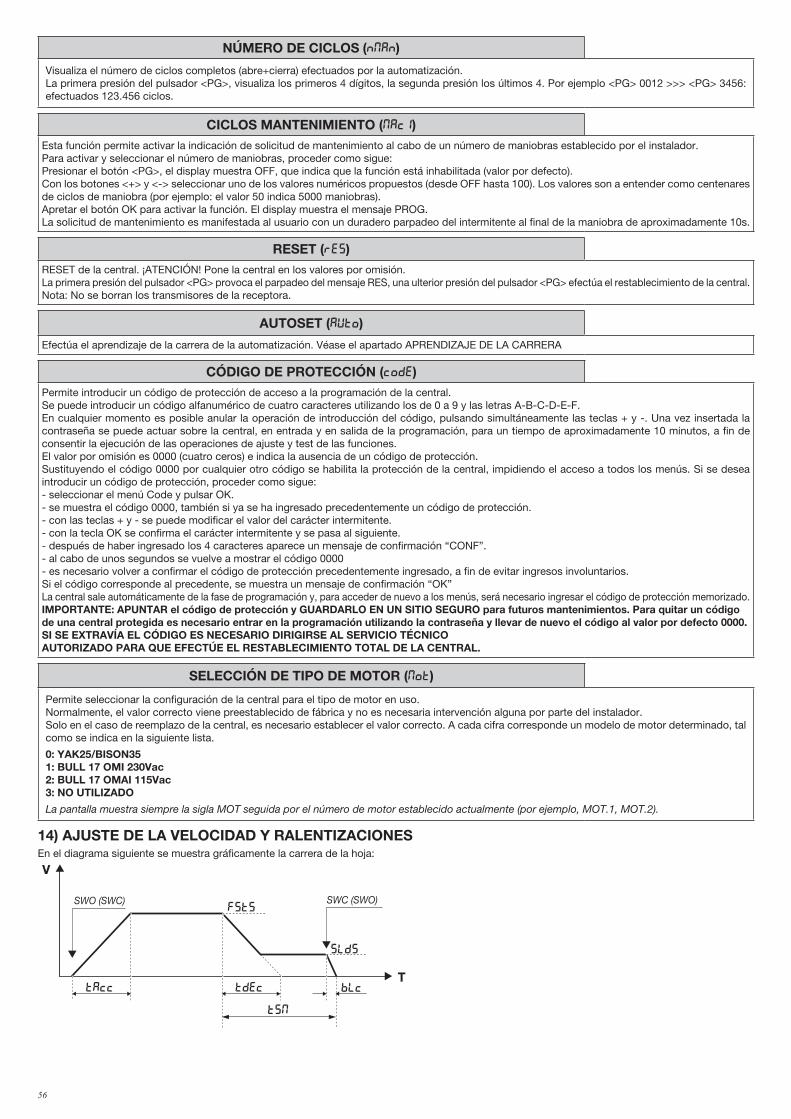
56
NÚMERO DE CICLOS (Nman)
Visualiza el número de ciclos completos (abre+cierra) efectuados por la automatización. La primera presión del pulsador <PG>, visualiza los primeros 4 dígitos, la segunda presión los últimos 4. Por ejemplo <PG> 0012 >>> <PG> 3456: efectuados 123.456 ciclos.
CICLOS MANTENIMIENTO (maci)Esta función permite activar la indicación de solicitud de mantenimiento al cabo de un número de maniobras establecido por el instalador.Para activar y seleccionar el número de maniobras, proceder como sigue:Presionar el botón <PG>, el display muestra OFF, que indica que la función está inhabilitada (valor por defecto). Con los botones <+> y <-> seleccionar uno de los valores numéricos propuestos (desde OFF hasta 100). Los valores son a entender como centenares de ciclos de maniobra (por ejemplo: el valor 50 indica 5000 maniobras).Apretar el botón OK para activar la función. El display muestra el mensaje PROG.La solicitud de mantenimiento es manifestada al usuario con un duradero parpadeo del intermitente al final de la maniobra de aproximadamente 10s.
RESET (RES)RESET de la central. ¡ATENCIÓN! Pone la central en los valores por omisión.La primera presión del pulsador <PG> provoca el parpadeo del mensaje RES, una ulterior presión del pulsador <PG> efectúa el restablecimiento de la central.Nota: No se borran los transmisores de la receptora.
AUTOSET (AUTO)
Efectúa el aprendizaje de la carrera de la automatización. Véase el apartado APRENDIZAJE DE LA CARRERA
CÓDIGO DE PROTECCIÓN (CODE)Permite introducir un código de protección de acceso a la programación de la central.Se puede introducir un código alfanumérico de cuatro caracteres utilizando los de 0 a 9 y las letras A-B-C-D-E-F.En cualquier momento es posible anular la operación de introducción del código, pulsando simultáneamente las teclas + y -. Una vez insertada la contraseña se puede actuar sobre la central, en entrada y en salida de la programación, para un tiempo de aproximadamente 10 minutos, a fin de consentir la ejecución de las operaciones de ajuste y test de las funciones.El valor por omisión es 0000 (cuatro ceros) e indica la ausencia de un código de protección.Sustituyendo el código 0000 por cualquier otro código se habilita la protección de la central, impidiendo el acceso a todos los menús. Si se desea introducir un código de protección, proceder como sigue:- seleccionar el menú Code y pulsar OK.- se muestra el código 0000, también si ya se ha ingresado precedentemente un código de protección.- con las teclas + y - se puede modificar el valor del carácter intermitente.- con la tecla OK se confirma el carácter intermitente y se pasa al siguiente.- después de haber ingresado los 4 caracteres aparece un mensaje de confirmación “CONF”.- al cabo de unos segundos se vuelve a mostrar el código 0000- es necesario volver a confirmar el código de protección precedentemente ingresado, a fin de evitar ingresos involuntarios.Si el código corresponde al precedente, se muestra un mensaje de confirmación “OK”La central sale automáticamente de la fase de programación y, para acceder de nuevo a los menús, será necesario ingresar el código de protección memorizado.IMPORTANTE: APUNTAR el código de protección y GUARDARLO EN UN SITIO SEGURO para futuros mantenimientos. Para quitar un código de una central protegida es necesario entrar en la programación utilizando la contraseña y llevar de nuevo el código al valor por defecto 0000.SI SE EXTRAVÍA EL CÓDIGO ES NECESARIO DIRIGIRSE AL SERVICIO TÉCNICO AUTORIZADO PARA QUE EFECTÚE EL RESTABLECIMIENTO TOTAL DE LA CENTRAL.
SELECCIÓN DE TIPO DE MOTOR (mot)
Permite seleccionar la configuración de la central para el tipo de motor en uso.Normalmente, el valor correcto viene preestablecido de fábrica y no es necesaria intervención alguna por parte del instalador.Solo en el caso de reemplazo de la central, es necesario establecer el valor correcto. A cada cifra corresponde un modelo de motor determinado, tal como se indica en la siguiente lista.
0: YAK25/BISON351: BULL 17 OMI 230Vac2: BULL 17 OMAI 115Vac3: NO UTILIZADO
La pantalla muestra siempre la sigla MOT seguida por el número de motor establecido actualmente (por ejemplo, MOT.1, MOT.2).
14) AJUSTE DE LA VELOCIDAD Y RALENTIZACIONESEn el diagrama siguiente se muestra gráficamente la carrera de la hoja:
V
T
FSTS
slds
BLcTAcc Tdec
TSM
SWO (SWC) SWC (SWO)
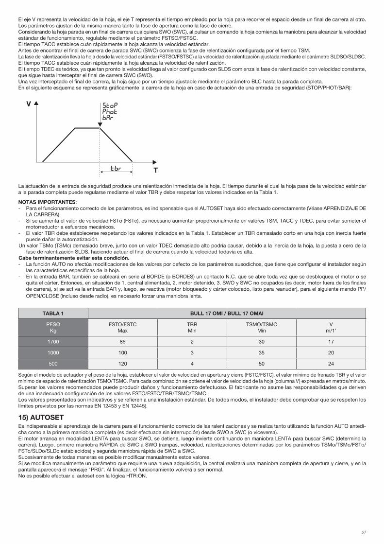
57
El eje V representa la velocidad de la hoja, el eje T representa el tiempo empleado por la hoja para recorrer el espacio desde un final de carrera al otro. Los parámetros ajustan de la misma manera tanto la fase de apertura como la fase de cierre.Considerando la hoja parada en un final de carrera cualquiera SWO (SWC), al pulsar un comando la hoja comienza la maniobra para alcanzar la velocidad estándar de funcionamiento, regulable mediante el parámetro FSTSO/FSTSC. El tiempo TACC establece cuán rápidamente la hoja alcanza la velocidad estándar.Antes de encontrar el final de carrera de parada SWC (SWO) comienza la fase de relentización configurada por el tiempo TSM.La fase de ralentización lleva la hoja desde la velocidad estándar (FSTSO/FSTSC) a la velocidad de ralentización ajustada mediante el parámetro SLDSO/SLDSC.El tiempo TACC establece cuán rápidamente la hoja alcanza la velocidad de ralentización.El tiempo TDEC es teórico, ya que tan pronto la velocidad llega al valor configurado con SLDS comienza la fase de ralentización con velocidad constante, que sigue hasta interceptar el final de carrera SWC (SWO).Una vez interceptado el final de carrera, la hoja sigue por un tiempo ajustable mediante el parámetro BLC hasta la parada completa.En el siguiente esquema se representa gráficamente la carrera de la hoja en caso de actuación de una entrada de seguridad (STOP/PHOT/BAR):
V
T
FSTo/fstc
sldo/SldC
BLo/blcTAcc Tdec
TSMo/tsmc
SWO (SWC) SWC (SWO)
V
Ttbr
stopphotbar
La actuación de la entrada de seguridad produce una ralentización inmediata de la hoja. El tiempo durante el cual la hoja pasa de la velocidad estándar a la parada completa puede regularse mediante el valor TBR y debe respetar los valores indicados en la Tabla 1.
NOTAS IMPORTANTES:- Para el funcionamiento correcto de los parámetros, es indispensable que el AUTOSET haya sido efectuado correctamente (Véase APRENDIZAJE DE
LA CARRERA).- Si se aumenta el valor de velocidad FSTo (FSTc), es necesario aumentar proporcionalmente en valores TSM, TACC y TDEC, para evitar someter el
motorreductor a esfuerzos mecánicos.- El valor TBR debe establecerse respetando los valores indicados en la Tabla 1. Establecer un TBR demasiado corto en una hoja con inercia fuerte
puede dañar la automatización. Un valor TSMo (TSMc) demasiado breve, junto con un valor TDEC demasiado alto podría causar, debido a la inercia de la hoja, la puesta a cero de la
fase de ralentización SLDS, haciendo actuar el final de carrera cuando la velocidad todavía es alta. Cabe terminantemente evitar esta condición.- La función AUTO no efectúa modificaciones de los valores por defecto de los parámetros susodichos, que tiene que configurar el instalador según
las características específicas de la hoja.- En la entrada BAR, también se cableará en serie al BORDE (o BORDES) un contacto N.C. que se abre toda vez que se desbloquea el motor o se
quita el cárter. Entonces, en situación de 1. central alimentada, 2. motor detenido, 3. SWO y SWC no ocupados (es decir, motor fuera de los finales de carrera), si se activa la entrada BAR y, luego, se reactiva (motor bloqueado y cárter colocado, listo para reanudar), para el siguiente mando PP/OPEN/CLOSE (incluso desde radio), es necesario forzar una maniobra lenta.
TABLA 1 BULL 17 OMI / BULL 17 OMAI
PESOKg
FSTO/FSTCMax
TBRMin
TSMO/TSMCMin
Vm/1'
1700 85 2 30 17
1000 100 3 35 20
500 120 4 50 24
Según el modelo de actuador y el peso de la hoja, establecer el valor de velocidad en apertura y cierre (FSTO/FSTC), el valor mínimo de frenado TBR y el valor mínimo de espacio de ralentización TSMO/TSMC. Para cada combinación se obtiene el valor de velocidad de la hoja (columna V) expresada en metros/minuto.Superar los valores recomendados puede producir daños y funcionamiento defectuoso. El fabricante no asume las responsabilidades que deriven de una inadecuada configuración de los valores FSTO/FSTC/TBR/TSMO/TSMC.Los valores presentados son indicativos y se refieren a una instalación estándar. De todos modos, el instalador debe comprobar que se respeten los límites previstos por las normas EN 12453 y EN 12445).
15) AUTOSETEs indispensable el aprendizaje de la carrera para el funcionamiento correcto de las ralentizaciones y se realiza tanto utilizando la función AUTO antedi-cha como a la primera maniobra completa (es decir efectuada sin interrupción) desde SWO a SWC (o viceversa).El motor arranca en modalidad LENTA para buscar SWO, se detiene, luego invierte continuando en maniobra LENTA para buscar SWC (determino la carrera). Luego, primero maniobra RÁPIDA de SWC a SWO (rampas, velocidad, ralentizaciones determinadas por los parámetros TSMo/TSMc/FSTo/FSTc/SLDo/SLDc establecidos) y segunda maniobra rápida de SWO a SWC.Sucesivamente de todas maneras es posible modificar manualmente estos valores.Si se modifica manualmente un parámetro que requiere una nueva adquisición, la central realizará una maniobra completa de apertura y cierre, y en la pantalla aparecerá el mensaje "PRG". Al finalizar, el funcionamiento volverá a ser normal.No es posible efectuar el autoset con la lógica HTR:ON.
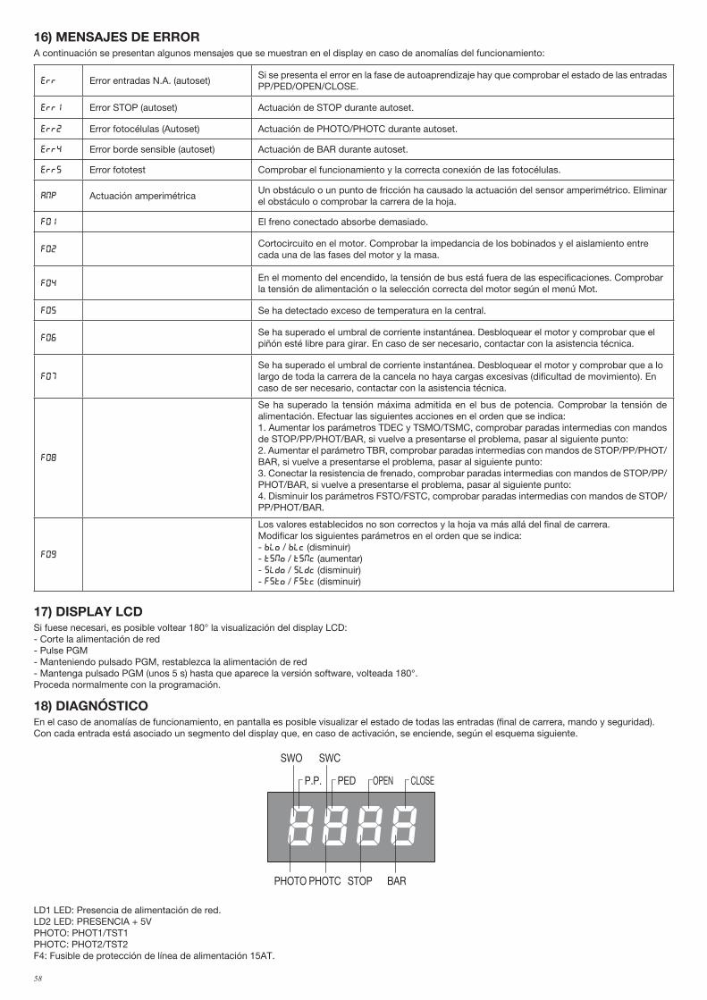
58
16) MENSAJES DE ERRORA continuación se presentan algunos mensajes que se muestran en el display en caso de anomalías del funcionamiento:
err Error entradas N.A. (autoset)Si se presenta el error en la fase de autoaprendizaje hay que comprobar el estado de las entradas PP/PED/OPEN/CLOSE.
Err1 Error STOP (autoset) Actuación de STOP durante autoset.
Err2 Error fotocélulas (Autoset) Actuación de PHOTO/PHOTC durante autoset.
Err4 Error borde sensible (autoset) Actuación de BAR durante autoset.
Err5 Error fototest Comprobar el funcionamiento y la correcta conexión de las fotocélulas.
amp Actuación amperimétricaUn obstáculo o un punto de fricción ha causado la actuación del sensor amperimétrico. Eliminar el obstáculo o comprobar la carrera de la hoja.
f01 El freno conectado absorbe demasiado.
F02Cortocircuito en el motor. Comprobar la impedancia de los bobinados y el aislamiento entre cada una de las fases del motor y la masa.
F04En el momento del encendido, la tensión de bus está fuera de las especificaciones. Comprobar la tensión de alimentación o la selección correcta del motor según el menú Mot.
F05 Se ha detectado exceso de temperatura en la central.
F06Se ha superado el umbral de corriente instantánea. Desbloquear el motor y comprobar que el piñón esté libre para girar. En caso de ser necesario, contactar con la asistencia técnica.
F07
Se ha superado el umbral de corriente instantánea. Desbloquear el motor y comprobar que a lo largo de toda la carrera de la cancela no haya cargas excesivas (dificultad de movimiento). En caso de ser necesario, contactar con la asistencia técnica.
F08
Se ha superado la tensión máxima admitida en el bus de potencia. Comprobar la tensión de alimentación. Efectuar las siguientes acciones en el orden que se indica:1. Aumentar los parámetros TDEC y TSMO/TSMC, comprobar paradas intermedias con mandos de STOP/PP/PHOT/BAR, si vuelve a presentarse el problema, pasar al siguiente punto:2. Aumentar el parámetro TBR, comprobar paradas intermedias con mandos de STOP/PP/PHOT/BAR, si vuelve a presentarse el problema, pasar al siguiente punto:3. Conectar la resistencia de frenado, comprobar paradas intermedias con mandos de STOP/PP/PHOT/BAR, si vuelve a presentarse el problema, pasar al siguiente punto:4. Disminuir los parámetros FSTO/FSTC, comprobar paradas intermedias con mandos de STOP/PP/PHOT/BAR.
F09
Los valores establecidos no son correctos y la hoja va más allá del final de carrera.Modificar los siguientes parámetros en el orden que se indica:- blo / blc (disminuir)- tsmo / tsmc (aumentar)- sldo / sldc (disminuir)- fsto / fstc (disminuir)
17) DISPLAY LCDSi fuese necesari, es posible voltear 180° la visualización del display LCD:- Corte la alimentación de red- Pulse PGM- Manteniendo pulsado PGM, restablezca la alimentación de red- Mantenga pulsado PGM (unos 5 s) hasta que aparece la versión software, volteada 180°. Proceda normalmente con la programación.
18) DIAGNÓSTICOEn el caso de anomalías de funcionamiento, en pantalla es posible visualizar el estado de todas las entradas (final de carrera, mando y seguridad). Con cada entrada está asociado un segmento del display que, en caso de activación, se enciende, según el esquema siguiente.
PHOTO
SWC
STOP
SWO
PHOTC BAR
P.P. PED OPEN CLOSE
LD1 LED: Presencia de alimentación de red.LD2 LED: PRESENCIA + 5VPHOTO: PHOT1/TST1PHOTC: PHOT2/TST2F4: Fusible de protección de línea de alimentación 15AT.
59
19) MANTENIMIENTOLa siguiente tabla sirve para registrar las intervenciones de mantenimiento, mejora o reparación por parte del técnico especializado.
Fecha _ _ _ _ _ _ _ _ _ _ _ _ _ _ _ _ _ _ _ _ _ _ _ _ _ _ _ _ _ _ _ _ Firma del técnico _ _ _ _ _ _ _ _ _ _ _ _ _ _ _ _ _ _ _ _ _ _ _ _ _ _ Sello
Descripción de la intervención
_ _ _ _ _ _ _ _ _ _ _ _ _ _ _ _ _ _ _ _ _ _ _ _ _ _ _ _ _ _ _ _ _ _ _ _ _ _ _ _ _ _ _ _ _ _ _ _ _ _ _ _ _ _ _ _ _ _ _ _ _ _ _ _ _ _ _ _ _ _ _ _ _
_ _ _ _ _ _ _ _ _ _ _ _ _ _ _ _ _ _ _ _ _ _ _ _ _ _ _ _ _ _ _ _ _ _ _ _ _ _ _ _ _ _ _ _ _ _ _ _ _ _ _ _ _ _ _ _ _ _ _ _ _ _ _ _ _ _ _ _ _ _ _ _ _
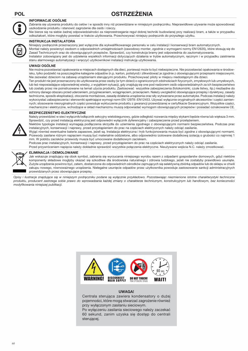
60
POL OSTRZEŻENIAINFORMACJE OGÓLNE Zabrania się używania produktu do celów i w sposób inny niż przewidziane w niniejszym podręczniku. Nieprawidłowe używanie może spowodować uszkodzenie produktu i stanowić zagrożenie dla osób i rzeczy. Nie bierze się na siebie żadnej odpowiedzialności za nieprzestrzeganie reguł dobrej techniki budowlanej przy realizacji bram, a także w przypadku odkształceń, które mogłyby powstać w trakcie użytkowania. Przechowywać niniejszy podręcznik do przyszłego użytku.
INSTRUKCJA INSTALATORA Niniejszy podręcznik przeznaczony jest wyłącznie dla wykwalifikowanego personelu w celu instalacji I konserwacji bram automatycznych. Montaż należy powierzyć osobom o odpowiednich umiejętnościach (zawodowy monter, zgodnie z wymogami normy EN12635), które stosują się do Zasad Technicznych oraz do obowiązujących przepisów. Sprawdzić, czy konstrukcja bramy jest odpowiednia do zautomatyzowania.Instalator zobowiązany jest do udzielenia wszelkich informacji dotyczących działania w trybie automatycznym, ręcznym i w przypadku zaistnienia stanu alarmowego automatyzacji i wręczyć użytkownikowi instalacji instrukcję użytkowania.
UWAGI OGÓLNE Nie można pozostawiać opakowania w miejscach dostępnych dla dieci, ponieważ może to być niebezpieczne. Nie pozostawiać opakowania w środow-isku, tylko podzielić na poszczególne kategorie odpadów (n.p. karton, polistyrol) i zlikwidować je zgodnie z obowiązującymi przepisami miejscowymi. Nie zezwalać dzieciom na zabawę urządzeniami sterującymi produktu. Przechowywać piloty w miejscu niedostępnym dla dzieci.Ten produkt nie jest przeznaczony do użytkowania przez osoby (w tym dzieci) o ograniczonych zdolnościach fizycznych, zmysłowych lub umysłowych, lub też nieposiadające odpowiedniej wiedzy, z wyjątkiem sytuacji, gdy znajdują się one pod nadzorem osób odpowiedzialnych za ich bezpieczeństwo lub zostały przez nie poinstruowane na temat użycia produktu. Zastosować wszystkie zabezpieczenia (fotokomórki, czułe listwy, itp.) niezbędne do ochrony danego obszaru przed uderzeniem, przygnieceniem, wciągnięciem, przecięciem. Należy uwzglednić obowiązujące przepisy i dyrektywy, zasady techniczne, sposób eksploatacji, otoczenie montażowe, zasadę działania urządzenia oraz siły wytwarzane przez automatyke. Podczas instalacji należy wykorzystać zabezpieczenia i sterowniki spełniające wymogi norm EN 12978 i EN12453. Używać wyłącznie oryginalnych akcesoriów i części zamien-nych; stosowanie nieoryginalnych części powoduje wykluczenie produktu z gwarancji przewidzianej w certyfikacie Gwarancyjnym. Wszystkie części, mechaniczne i elektryczne, wchodzące w skład mechanizmu muszą odpowiadać wymogom obowiązujących przepisów i posiadać oznakowanie CE.
BEZPIECZEŃSTWO ELEKTRYCZNENależy przewidzieć w sieci wyłącznik/odłącznik sekcyjny wielobiegunowy, gdzie odległość rozwarcia między stykami będzie równa lub większa 3 mm. Sprawdzić, czy przed instalacją elektryczną jest odpowiedni wyłącznik dyferencjalny i zabezpieczenie przed przetężeniem.Niektóre typologie instalacji wymagają podłączenia skrzydła do uziemienia zgodnego z obowiązującymi normami bezpieczeństwa. Podczas prac instalacyjnych, konserwacji i naprawy, przed przystąpieniem do prac na częściach elektrycznych należy odciąć zasilanie.Wyjąć również ewentualne baterie zapasowe, jeżeli są. Instalacja elektryczna i tryb funkcjonowania musza być zgodne z obowiązującymi normami. Przewody zasilane różnym napięciem muszą być materialnie oddzielone, albo odpowiednio izolowane dodatkową izolacją o grubości co najmniej 1 mm. W pobliżu zacisków przewody musza być umocowane dodatkowym zaciskiem.Podczas prac instalacyjnych, konserwacji i naprawy, przed przystąpieniem do prac na częściach elektrycznych należy odciąć zasilanie.Przed przywróceniem napięcia należy dokładnie sprawdzić wszystkie połączenia elektryczne. Nieużywane wejścia N.C. należy zmostkować.
ELIMINACJA I DEMOLOWANIEJak wskazuje znajdujący się obok symbol, zabrania się wyrzucania niniejszego wyrobu razem z odpadami gospodarstw domowych, gdyż niektóre komponenty składowe mogłyby okazać się szkodliwe dla środowiska naturalnego i zdrowia ludzkiego, jeżeli nie zostałyby prawidłowo usunięte. Zużyte urządzenie powinno być, zatem, dostarczone do odpowiednich ośrodków zajmujących się selektywną zbiórką odpadów lub do sklepu w chwili zakupu nowego, równoważnego urządzenia. Nielegalne usunięcie odpadów przez użytkownika powoduje zastosowanie sankcji administracyjnych przewidzianych przez obowiązujące przepisy.
Opisy i ilustracje znajdujące się w niniejszym podręczniku podane są wyłącznie przykładowo. Pozostawiając niezmienione istotne charakterystyki techniczne produktu, producent zastrzega sobie prawo do wprowadzania każdej zmiany o charakterze technicznym, konstrukcyjnym lub handlowym, bez konieczności modyfikowania niniejszej publikacji.
UWAGA!Centrala sterująca zawiera kondensatory o dużej pojemności, które mogą stwarzać zagrożenie również przy wyłączonym zasilaniu sieciowym. Po wyłączeniu zasilania sieciowego należy zaczekać 60 sekund, zanim uzyska się dostęp do centrali sterującej.
Read Instructions
DO NOT TOUCH!DISCONNECT M A I N S U P P LY WAIT!
60 sec.
WARNING!
F8369256
Etichetta WARNING: Formato 55x50mm
stampa su PVC adesivo4 colori
Read Instructions
DO NOT TOUCH!DISCONNECT M A I N S U P P LY WAIT!
60 sec.
WARNING!
F8369256
Etichetta WARNING: Formato 55x50mm
stampa su PVC adesivo4 colori
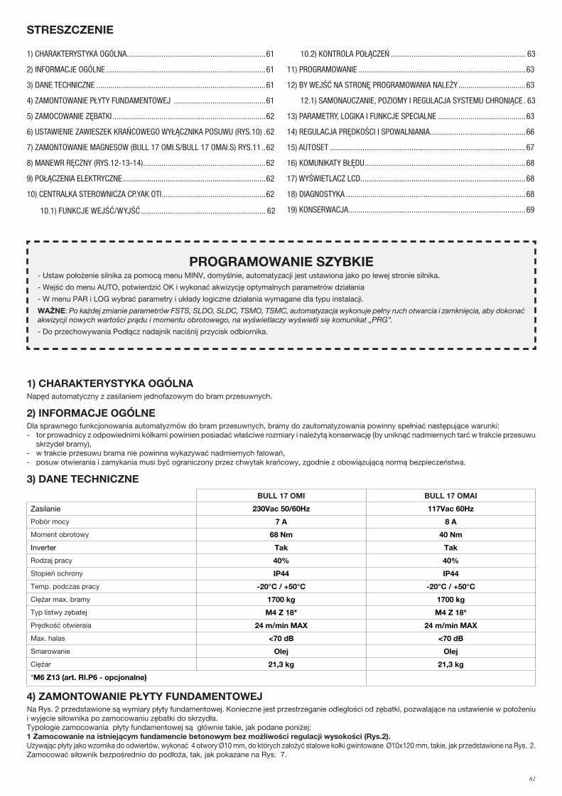
61
1) CHARAKTERYSTYKA OGÓLNANapęd automatyczny z zasilaniem jednofazowym do bram przesuwnych.
2) INFORMACJE OGÓLNEDla sprawnego funkcjonowania automatyzmów do bram przesuwnych, bramy do zautomatyzowania powinny spełniać następujące warunki:- tor prowadnicy z odpowiednimi kółkami powinien posiadać właściwe rozmiary i należytą konserwację (by uniknąć nadmiernych tarć w trakcie przesuwu
skrzydeł bramy),- w trakcie przesuwu brama nie powinna wykazywać nadmiernych falowań,- posuw otwierania i zamykania musi być ograniczony przez chwytak krańcowy, zgodnie z obowiązującą normą bezpieczeństwa.
3) DANE TECHNICZNE
BULL 17 OMI BULL 17 OMAI
Zasilanie 230Vac 50/60Hz 117Vac 60Hz
Pobór mocy 7 A 8 A
Moment obrotowy 68 Nm 40 Nm
Inverter Tak Tak
Rodzaj pracy 40% 40%
Stopień ochrony IP44 IP44
Temp. podczas pracy -20°C / +50°C -20°C / +50°C
Ciężar max. bramy 1700 kg 1700 kg
Typ listwy zębatej M4 Z 18* M4 Z 18*
Prędkość otwieraia 24 m/min MAX 24 m/min MAX
Max. halas <70 dB <70 dB
Smarowanie Olej Olej
Ciężar 21,3 kg 21,3 kg
*M6 Z13 (art. RI.P6 - opcjonalne)
4) ZAMONTOWANIE PŁYTY FUNDAMENTOWEJ Na Rys. 2 przedstawione są wymiary płyty fundamentowej. Konieczne jest przestrzeganie odległości od zębatki, pozwalające na ustawienie w położeniu i wyjęcie siłownika po zamocowaniu zębatki do skrzydła. Typologie zamocowania płyty fundamentowej są głównie takie, jak podane poniżej:1 Zamocowanie na istniejącym fundamencie betonowym bez możliwości regulacji wysokości (Rys.2). Używając płyty jako wzornika do odwiertów, wykonać 4 otwory Ø10 mm, do których założyć stalowe kołki gwintowane Ø10x120 mm, takie, jak przedstawione na Rys. 2. Zamocować siłownik bezpośrednio do podłoża, tak, jak pokazane na Rys. 7.
STRESZCZENIE
1) CHARAKTERYSTYKA OGÓLNA ....................................................................61
2) INFORMACJE OGÓLNE ..............................................................................61
3) DANE TECHNICZNE ...................................................................................61
4) ZAMONTOWANIE PŁYTY FUNDAMENTOWEJ .............................................61
5) ZAMOCOWANIE ZĘBATKI ...........................................................................62
6) USTAWIENIE ZAWIESZEK KRAŃCOWEGO WYŁĄCZNIKA POSUWU (RYS.10) .62
7) ZAMONTOWANIE MAGNESOW (BULL 17 OMI.S/BULL 17 OMAI.S) RYS.11 ..62
8) MANEWR RĘCZNY (RYS.12-13-14) ............................................................62
9) POŁĄCZENIA ELEKTRYCZNE ......................................................................62
10) CENTRALKA STEROWNICZA CP.YAK OTI ...................................................62
10.1) FUNKCJE WEJŚĆ/WYJŚĆ ............................................................. 62
10.2) KONTROLA POŁĄCZEŃ .................................................................. 63
11) PROGRAMOWANIE ..................................................................................63
12) BY WEJŚĆ NA STRONĘ PROGRAMOWANIA NALEŻY .................................63
12.1) SAMONAUCZANIE, POZIOMY I REGULACJA SYSTEMU CHRONIĄCE . 63
13) PARAMETRY, LOGIKA I FUNKCJE SPECIALNE ...........................................63
14) REGULACJA PRĘDKOŚCI I SPOWALNIANIA ...............................................66
15) AUTOSET ................................................................................................67
16) KOMUNIKATY BŁĘDU ...............................................................................68
17) WYŚWIETLACZ LCD .................................................................................68
18) DIAGNOSTYKA ........................................................................................68
19) KONSERWACJA.......................................................................................69
PROGRAMOWANIE SZYBKIE- Ustaw położenie silnika za pomocą menu MINV, domyślnie, automatyzacji jest ustawiona jako po lewej stronie silnika.
- Wejść do menu AUTO, potwierdzić OK i wykonać akwizycję optymalnych parametrów działania
- W menu PAR i LOG wybrać parametry i układy logiczne działania wymagane dla typu instalacji.
WAŻNE: Po każdej zmianie parametrów FSTS, SLDO, SLDC, TSMO, TSMC, automatyzacja wykonuje pełny ruch otwarcia i zamknięcia, aby dokonać akwizycji nowych wartości prądu i momentu obrotowego, na wyświetlaczy wyświetli się komunikat „PRG”.
- Do przechowywania Podłącz nadajnik naciśnij przycisk odbiornika.
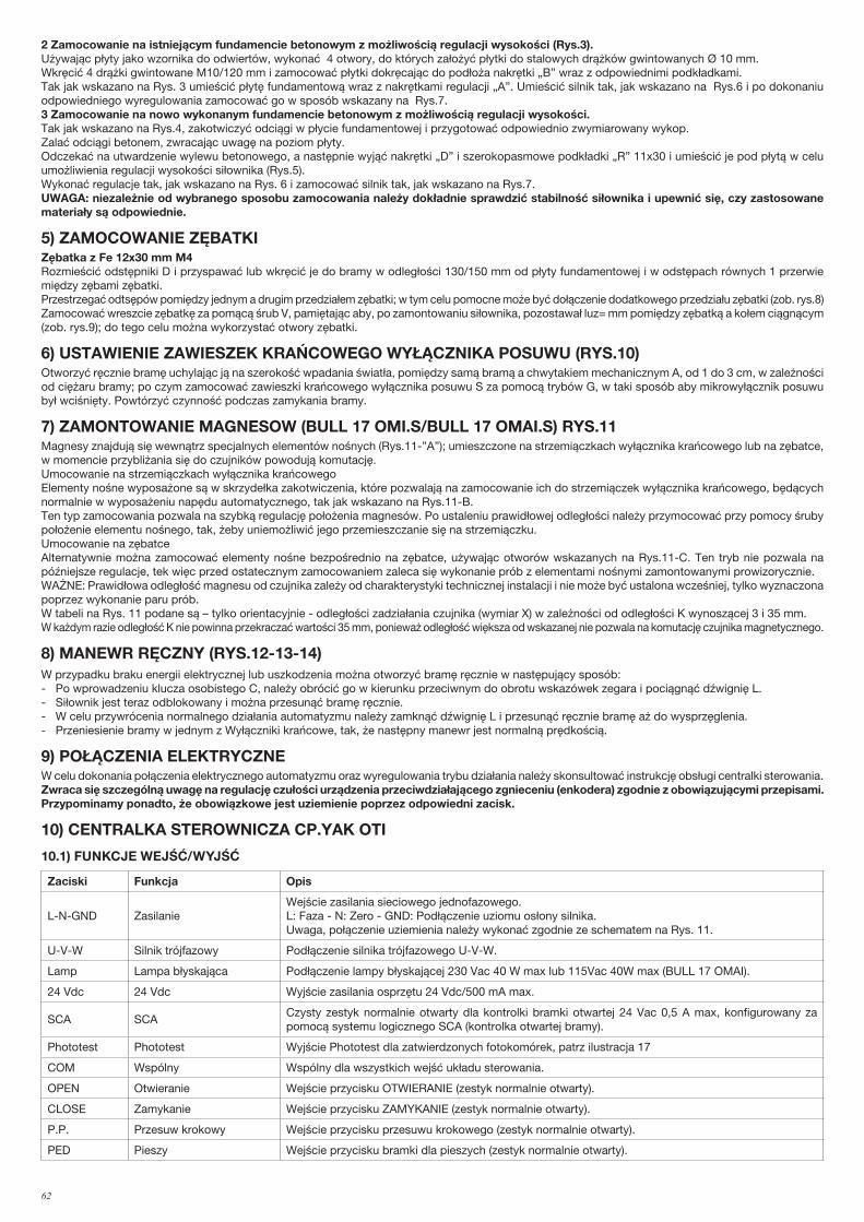
62
2 Zamocowanie na istniejącym fundamencie betonowym z możliwością regulacji wysokości (Rys.3). Używając płyty jako wzornika do odwiertów, wykonać 4 otwory, do których założyć płytki do stalowych drążków gwintowanych Ø 10 mm.Wkręcić 4 drążki gwintowane M10/120 mm i zamocować płytki dokręcając do podłoża nakrętki „B” wraz z odpowiednimi podkładkami.Tak jak wskazano na Rys. 3 umieścić płytę fundamentową wraz z nakrętkami regulacji „A”. Umieścić silnik tak, jak wskazano na Rys.6 i po dokonaniu odpowiedniego wyregulowania zamocować go w sposób wskazany na Rys.7.3 Zamocowanie na nowo wykonanym fundamencie betonowym z możliwością regulacji wysokości. Tak jak wskazano na Rys.4, zakotwiczyć odciągi w płycie fundamentowej i przygotować odpowiednio zwymiarowany wykop.Zalać odciągi betonem, zwracając uwagę na poziom płyty. Odczekać na utwardzenie wylewu betonowego, a następnie wyjąć nakrętki „D” i szerokopasmowe podkładki „R” 11x30 i umieścić je pod płytą w celu umożliwienia regulacji wysokości siłownika (Rys.5).Wykonać regulacje tak, jak wskazano na Rys. 6 i zamocować silnik tak, jak wskazano na Rys.7.UWAGA: niezależnie od wybranego sposobu zamocowania należy dokładnie sprawdzić stabilność siłownika i upewnić się, czy zastosowane materiały są odpowiednie.
5) ZAMOCOWANIE ZĘBATKIZębatka z Fe 12x30 mm M4Rozmieścić odstępniki D i przyspawać lub wkręcić je do bramy w odległości 130/150 mm od płyty fundamentowej i w odstępach równych 1 przerwie między zębami zębatki. Przestrzegać odtsępów pomiędzy jednym a drugim przedziałem zębatki; w tym celu pomocne może być dołączenie dodatkowego przedziału zębatki (zob. rys.8)Zamocować wreszcie zębatkę za pomącą śrub V, pamiętając aby, po zamontowaniu siłownika, pozostawał luz= mm pomiędzy zębatką a kołem ciągnącym (zob. rys.9); do tego celu można wykorzystać otwory zębatki.
6) USTAWIENIE ZAWIESZEK KRAŃCOWEGO WYŁĄCZNIKA POSUWU (RYS.10)Otworzyć ręcznie bramę uchylając ją na szerokość wpadania światła, pomiędzy samą bramą a chwytakiem mechanicznym A, od 1 do 3 cm, w zależności od ciężaru bramy; po czym zamocować zawieszki krańcowego wyłącznika posuwu S za pomocą trybów G, w taki sposób aby mikrowyłącznik posuwu był wciśnięty. Powtórzyć czynność podczas zamykania bramy.
7) ZAMONTOWANIE MAGNESOW (BULL 17 OMI.S/BULL 17 OMAI.S) RYS.11Magnesy znajdują się wewnątrz specjalnych elementów nośnych (Rys.11-”A”); umieszczone na strzemiączkach wyłącznika krańcowego lub na zębatce, w momencie przybliżania się do czujników powodują komutację. Umocowanie na strzemiączkach wyłącznika krańcowegoElementy nośne wyposażone są w skrzydełka zakotwiczenia, które pozwalają na zamocowanie ich do strzemiączek wyłącznika krańcowego, będących normalnie w wyposażeniu napędu automatycznego, tak jak wskazano na Rys.11-B.Ten typ zamocowania pozwala na szybką regulację położenia magnesów. Po ustaleniu prawidłowej odległości należy przymocować przy pomocy śruby położenie elementu nośnego, tak, żeby uniemożliwić jego przemieszczanie się na strzemiączku.Umocowanie na zębatceAlternatywnie można zamocować elementy nośne bezpośrednio na zębatce, używając otworów wskazanych na Rys.11-C. Ten tryb nie pozwala na późniejsze regulacje, tek więc przed ostatecznym zamocowaniem zaleca się wykonanie prób z elementami nośnymi zamontowanymi prowizorycznie.WAŻNE: Prawidłowa odległość magnesu od czujnika zależy od charakterystyki technicznej instalacji i nie może być ustalona wcześniej, tylko wyznaczona poprzez wykonanie paru prób. W tabeli na Rys. 11 podane są – tylko orientacyjnie - odległości zadziałania czujnika (wymiar X) w zależności od odległości K wynoszącej 3 i 35 mm.W każdym razie odległość K nie powinna przekraczać wartości 35 mm, ponieważ odległość większa od wskazanej nie pozwala na komutację czujnika magnetycznego.
8) MANEWR RĘCZNY (RYS.12-13-14)W przypadku braku energii elektrycznej lub uszkodzenia można otworzyć bramę ręcznie w następujący sposób:- Po wprowadzeniu klucza osobistego C, należy obrócić go w kierunku przeciwnym do obrotu wskazówek zegara i pociągnąć dźwignię L.- Siłownik jest teraz odblokowany i można przesunąć bramę ręcznie.- W celu przywrócenia normalnego działania automatyzmu należy zamknąć dźwignię L i przesunąć ręcznie bramę aż do wysprzęglenia.- Przeniesienie bramy w jednym z Wyłączniki krańcowe, tak, że następny manewr jest normalną prędkością.
9) POŁĄCZENIA ELEKTRYCZNEW celu dokonania połączenia elektrycznego automatyzmu oraz wyregulowania trybu działania należy skonsultować instrukcję obsługi centralki sterowania.Zwraca się szczególną uwagę na regulację czułości urządzenia przeciwdziałającego zgnieceniu (enkodera) zgodnie z obowiązującymi przepisami.Przypominamy ponadto, że obowiązkowe jest uziemienie poprzez odpowiedni zacisk.
10) CENTRALKA STEROWNICZA CP.YAK OTI
10.1) FUNKCJE WEJŚĆ/WYJŚĆ
Zaciski Funkcja Opis
L-N-GND ZasilanieWejście zasilania sieciowego jednofazowego.L: Faza - N: Zero - GND: Podłączenie uziomu osłony silnika.Uwaga, połączenie uziemienia należy wykonać zgodnie ze schematem na Rys. 11.
U-V-W Silnik trójfazowy Podłączenie silnika trójfazowego U-V-W.
Lamp Lampa błyskająca Podłączenie lampy błyskającej 230 Vac 40 W max lub 115Vac 40W max (BULL 17 OMAI).
24 Vdc 24 Vdc Wyjście zasilania osprzętu 24 Vdc/500 mA max.
SCA SCACzysty zestyk normalnie otwarty dla kontrolki bramki otwartej 24 Vac 0,5 A max, konfigurowany za pomocą systemu logicznego SCA (kontrolka otwartej bramy).
Phototest Phototest Wyjście Phototest dla zatwierdzonych fotokomórek, patrz ilustracja 17
COM Wspólny Wspólny dla wszystkich wejść układu sterowania.
OPEN Otwieranie Wejście przycisku OTWIERANIE (zestyk normalnie otwarty).
CLOSE Zamykanie Wejście przycisku ZAMYKANIE (zestyk normalnie otwarty).
P.P. Przesuw krokowy Wejście przycisku przesuwu krokowego (zestyk normalnie otwarty).
PED Pieszy Wejście przycisku bramki dla pieszych (zestyk normalnie otwarty).

63
STOP Stop Wejście przycisku STOP (zestyk normalnie zamknięty).
PHOTO Fotokomórka otwierania Wejście dla fotokomórki aktywnej tylko na etapie otwierania
PHOTC Fotokomórka zamykania Wejście dla fotokomórki aktywnej tylko na etapie zamykania
COM Wspólny Wspólne dla wyłącznika krańcowego
SWCWyłącznik krańcowy zamykania
Wejście wyłącznika krańcowego ZAMYKANIE (zestyk normalnie zamknięty).
SWOWyłącznik krańcowy otwierania
Wejście wyłącznika krańcowego OTWIERANIE (zestyk normalnie zamknięty).
BARKrawędziowa listwazabezpieczająca
Wejście stykowe listwy krawędziowejKrawędź elektroniczna (8K2): Jumper JP1 “BAR” zwartyKrawędź mechaniczna (normalnie zamknięty): Jumper JP1 “BAR” otwartyZadziałanie krawędzi powoduje zatrzymanie ruchu skrzydła i odwraca kierunek biegu na około 3 s.Uwaga: Ten wpis jest podłączony transformator bezpieczeństwa zamontowane na dłoni dźwignię zwalniającą, która zapobiega każdy manewr, jeśli silnik jest zwolniony.Wrażliwe krawędzi musi być podłączony w serii do tej mikroprzełącznik, jak pokazano w rysunek 21
RADIO Radioodbiornik Szybkie złącze wtyczkę odbiornika radiowego.
2CH Drugi kanał Wyjście normalnie otwarte drugiego kanału radiowego radioodbiornika. (max 24 Vac/dc 1 A)
HAMULEC Rezystor hamulcaWejście rezystora rozpraszającego prąd hamowania.Opór jest używana tylko na 230V BULL 17 OMI
P3 Nie używane
CON1 Nie używane
J7 Nie używane
J8 Nie używane
SW1 Dip1, Dip2 Ustawić na WŁ.
U1PAMIĘĆ KONFIGURACJI
Wyjmowana karta pamięci E-Eprom. Zawiera zapis wszystkich konfiguracji centralki (logika, parametry itp.), z wyjątkiem nadajników radiowych. W przypadku usterki istnieje możliwość wyjęcia karty E-Eprom i włożenia jej do innej centralki bez konieczności ponownego programowania.
10.2) KONTROLA POŁĄCZEŃ1) Odłączyć zasilanie.2) Ręcznie odblokować drzwi, przesunąć je mniej więcej do połowy toru i ponownie zablokować.3) Wznowić dopływ zasilania.4) Wydać polecenie trybu krokowego za pomocą przycisku <-> na centralce sterowniczej (przy wyłączonym wyświetlaczu LCD), aby zatrzymać skrzydło
ponownie nacisnąć <->.5) Skrzydło powinna przesuwać się w kierunku otwarcia, w innym razie posłużyć się logiką MINV aby zmienić kierunek otwierania (Default MINV=OFF)
silnik zainstalowany z lewej strony.
11) PROGRAMOWANIEProgramowanie różnych funkcji centralki dokonywane jest za pomocą wyświetlacza LCD, znajdującego się na pulpicie centralki, wprowadzając, opi-sane poniżej, obrane wartości do menu programowania. Menu z parametrami pozwala nastawić jedną wartość numeryczną dla jednej funkcji, w sposób analogiczny do trimera regulacyjnego.Menu logiki umożliwia włączanie lub wyłączanie jednej z funkcji, w sposób analogiczny do nastawiania jednego z dip-switch.Inne funkcje specialn występują po menu parametrów i menu logiki i mogą zmieniać się one w zależności od rodzaju centralki lub rodzaju kontroli wykonywanej przez software.
12) BY WEJŚĆ NA STRONĘ PROGRAMOWANIA NALEŻY1 – Nacisnąć przycisk <PG>, display wyświetla pierwsze menu z Parametrami “PAR”. 2 – Wybrać za pomocą przycisku <+> lub <-> menu do zaprogramowania.3- Nacisnąć przycisk <PG>, display wyświetla pierwszą dostępną w menu funkcję.4 – Wybrać za pomocą przycisku <+> lub <-> funkcję do zaprogramowania.5 – Nacisnąć przycisk <PG>, display wyświetla aktualną nastawioną wartość dla wyselekcjonowanej funkcji.6 – Wyselekcjonować za pomocą przycisku <+> lub <-> wartość którą zamierza się przydzielić funkcji.7 - Nacisnąć <PG>, display wyświetla skrót “PRG” sygnalizujący wykonanie zaprogramowania.
12.1) SAMONAUCZANIE, POZIOMY I REGULACJA SYSTEMU chroniącego przed przytrzaśnięciemPo zamontowaniu automatyzmu i wykonaniu połączeń elektrycznych oraz zaprogramowaniu wszystkich żądanych funkcji należy wykonać proces samonauczania i pracy pary.Wejść do menu AUTO i wcisnąć przycisk <PG>Na wyświetlaczu cyfrowym pojawi się napis PUSH.Wcisnąć ponownie przycisk <PG>, rozpocznie się procedura samoregulacji i na wyświetlaczu cyfrowym pojawi się napis PRG, podczas gdy wydawne zostają co najmniej 2 polecenia pełnego manewru. Po zakończeniu procedury na wyświetlaczu cyfrowym pojawi się napis OK.Procedura może być wykonana w każdym położeniu bramy i może być przerwana w każdej chwili przez jednoczesne wciśnięcie przycisków <+> i <->, albo po zadziałaniu wejść STOP/PHO/PHA/BAR/PP/PED.Jeżeli procedura nie zakończyła się pomyślnie, jest wyświetlany komunikat błędu ERR, należy sprawdzić obecność ewentualnych przeszkód lub punktów tarcia skrzydła.Na końcu etapu automatycznej konfiguracji sprawdzić wartość sił roboczych zgodnie z wymogami EN12445 i EN12453. Jeśli wartość siły jest zbyt wysoka, zainstalować listwę zgodną z EN12978.Uwagi: Wcisnięcie przycisku <-> na wyświetlaczu cyfrowym zgaszonym odpowiada impulsowi P.P.Jednoczesne naciskanie przycisków <+> i <-> pełni wewnątrz menu funkcję umożliwiającą powrót do menu nadrzędnego bez wprowadzania zmian. Przytrzymując naciśnięty przycisk <+> lub przycisk <-> przyspiesza się wzrastanie/zmniejszanie się wartości.Po upływie 60s centralka wyłącza się z układu programowania i wyłącza wyświetlacz.

64
13) PARAMETRY, LOGIKA I FUNKCJE SPECIALNEW poniższych tabelach opisane są poszczególne funkcje wykonywane przez centralkę.
PARAMETRY (PAR)
MENU FUNKCJA MIN-MAX-(Default) MEMO
TCACzas automatycznego zamykania. Jest aktywne tylko przy logice „TCA”=ONPo upływie ustawionego czasu centralka wydaje polecenie wykonania manewru zamykania. 1-240-(40s)
TpedReguluje tor przebiegu skrzydła podczas częściowego otwierania sterowanego przez wejście dla pieszych. Wartość jest wyrażona procentowo w odniesieniu do całkowitej wartości toru.
5-100-(20%)
tsmoReguluje czas trwania fazy spowalniania podczas otwierania.Wartość jest wyrażona procentowo w odniesieniu do całkowitej wartości toru.Zobacz paragraf “Regulacja prędkości i spowalniania”.
10-100-(20%)
tsmcReguluje czas trwania fazy spowalniania podczas i zamykania. Wartość jest wyrażona procentowo w odniesieniu do całkowitej wartości toru.Zobacz paragraf “Regulacja prędkości i spowalniania”.
10-100-(20%)
FSToReguluje prędkość skrzydła podczas otwierania i zamykania.WAŻNE: Wartość tego parametru powinna być zmieniana wyłącznie pod warunkiem przestrzegania ograniczeń ciężaru podanych w Tabeli 1.Zobacz paragraf “Regulacja prędkości i spowalniania”.
20-120-(45)
fstcReguluje prędkość skrzydła podczas otwierania i zamykania.WAŻNE: Wartość tego parametru powinna być zmieniana wyłącznie pod warunkiem przestrzegania ograniczeń ciężaru podanych w Tabeli 1.Zobacz paragraf “Regulacja prędkości i spowalniania”.
20-120-(45)
sldoReguluje prędkość podczas fazy spowalniania podczas otwierania.Zobacz paragraf „Regulacja prędkości i spowalniania”*. 10-40-(25)
sldcReguluje prędkość podczas fazy spowalniania podczas zamykania.Zobacz paragraf „Regulacja prędkości i spowalniania”*. 10-40-(25)
PMO Reguluje moment silnika podczas fazy otwierania*. 1-99-(85%)
PMC Reguluje moment silnika podczas fazy zamykania*. 1-99-(85%)
sEavReguluje próg interwencji mechanizmu zapobiegającego przygnieceniu (Amperomierz) pod-czas fazy normalnej prędkości.* 0:Off -99:maksymalna czułość - 1: minimalna czułość
Ø-99-(60%)
sEarReguluje próg interwencji mechanizmu zapobiegającego przygnieceniu (Amperomierz) pod-czas fazy spowalniania.*0:Off -99:maksymalna czułość - 1: minimalna czułość
Ø-99-(60%)
bloReguluje odległość zatrzymania po dotarciu do wyłącznika krańcowego otwierania.Wartość wyrażona w cm. Zobacz paragraf “Regulacja prędkości i spowalniania”.
1-10-(3)
blcReguluje odległość zatrzymania po dotarciu do wyłącznika krańcowego zamykania. Wartość wyrażona w cm. Zobacz paragraf “Regulacja prędkości i spowalniania”.
1-10-(3)
TLSAktywne tylko jeżeli parametr AUX jest ustawiony na wartość 1. Reguluje czas aktywacji światła roboczego. 1-240-(60s)
TACCNachylenie rampy podczas przyspieszania. Wartość wyrażona w dziesiętnych sekundy.Zobacz paragraf “Regulacja prędkości i spowalniania”. 1-25-(20)
TDEC Nachylenie rampy podczas spowalniania. 50-99-(50)
TbrHamowanie awaryjne na skutek interwencji wejść PHOT/BAR/STOP, wartość wyrażona w dziesiętnych sekundy.(W celu dokonania regulacji patrz tabela 1.)
1-20-(7)
spin
Reguluje odległość odwrócenia biegu, którą pokonuje skrzydło po zadziałaniu listwy krawędziowej (COSTA). Podczas fazy odwrócenia biegu dalsze interwencje listwy krawędziowej są ignorowane. Zadziałanie listwy krawędziowej powoduje zatrzymanie. Jeśli podczas odwrócenia kierunku biegu (w kierunku OTWIERANIE i ZAMYKANIE) odpowiednia fotokomórka (PHOTO lub PHOTC) jest aktywna, parametr ten jest ignorowany, natomiast odległość odwrócenia kierunku biegu musi być minimalna (10 cm).Wartość minimalna 1 jest równa około 20 cm, wartość maksymalna 4 jest równa około 60 cm.
1-4-(1)
AUX
Zaznacza tryb funkcjonowania wyjścia AUX:0: SCA1: Oświetlenie robocze. Styk zamyka się na okres czasu ustawiony w parametrze TLS. Zliczai-nie zaczyna się wraz z rozpoczęciem manewru otwierania.2: Oświetlenie strefowe. Styk zamyka się podczas manewru otwierania i pozostaje zamknięty przez cały czas TCA i otwiera się ponownie tylko po zamknięciu bramy.Zobacz podłączenia na Rysunku 17.
Ø-2-(Ø)
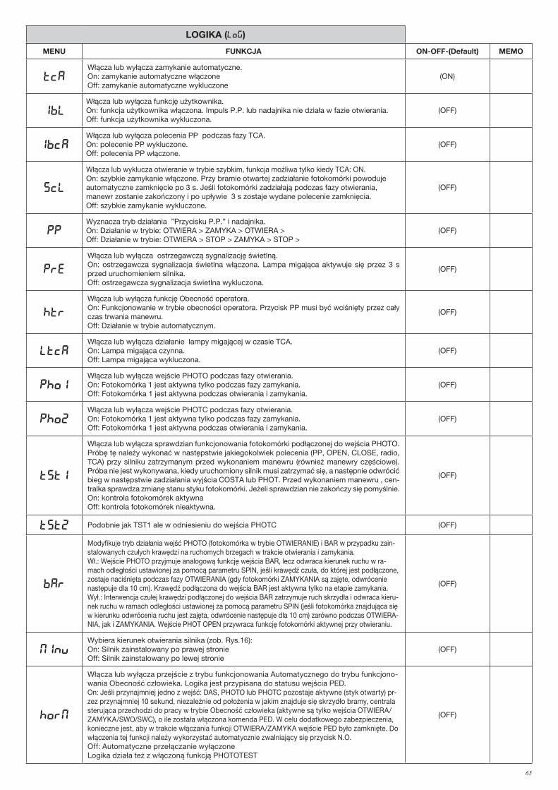
65
LOGIKA (LOG)
MENU FUNKCJA ON-OFF-(Default) MEMO
TCAWłącza lub wyłącza zamykanie automatyczne.On: zamykanie automatyczne włączoneOff: zamykanie automatyczne wykluczone
(ON)
IBLWłącza lub wyłącza funkcję użytkownika.On: funkcja użytkownika włączona. Impuls P.P. lub nadajnika nie działa w fazie otwierania.Off: funkcja użytkownika wykluczona.
(OFF)
IBCAWłącza lub wyłącza polecenia PP podczas fazy TCA.On: polecenie PP wykluczone.Off: polecenia PP włączone.
(OFF)
SCL
Włącza lub wyklucza otwieranie w trybie szybkim, funkcja możliwa tylko kiedy TCA: ON.On: szybkie zamykanie włączone. Przy bramie otwartej zadziałanie fotokomórki powoduje automatyczne zamknięcie po 3 s. Jeśli fotokomórki zadziałają podczas fazy otwierania, manewr zostanie zakończony i po upływie 3 s zostaje wydane polecenie zamknięcia.Off: szybkie zamykanie wykluczone.
(OFF)
PPWyznacza tryb działania ”Przycisku P.P.” i nadajnika.On: Działanie w trybie: OTWIERA > ZAMYKA > OTWIERA >Off: Działanie w trybie: OTWIERA > STOP > ZAMYKA > STOP >
(OFF)
PRE
Włącza lub wyłącza ostrzegawczą sygnalizację świetlną.On: ostrzegawcza sygnalizacja świetlna włączona. Lampa migająca aktywuje się przez 3 s przed uruchomieniem silnika.Off: ostrzegawcza sygnalizacja świetlna wykluczona.
(OFF)
HTR
Włącza lub wyłącza funkcję Obecność operatora. On: Funkcjonowanie w trybie obecności operatora. Przycisk PP musi być wciśnięty przez cały czas trwania manewru.Off: Działanie w trybie automatycznym.
(OFF)
LTCAWłącza lub wyłącza działanie lampy migającej w czasie TCA.On: Lampa migająca czynna.Off: Lampa migająca wykluczona.
(OFF)
Pho1Włącza lub wyłącza wejście PHOTO podczas fazy otwierania.On: Fotokomórka 1 jest aktywna tylko podczas fazy zamykania.Off: Fotokomórka 1 jest aktywna podczas otwierania i zamykania.
(OFF)
Pho2Włącza lub wyłącza wejście PHOTC podczas fazy otwierania.On: Fotokomórka 1 jest aktywna tylko podczas fazy zamykania.Off: Fotokomórka 1 jest aktywna podczas otwierania i zamykania.
(OFF)
tst1
Włącza lub wyłącza sprawdzian funkcjonowania fotokomórki podłączonej do wejścia PHOTO.Próbę tę należy wykonać w następstwie jakiegokolwiek polecenia (PP, OPEN, CLOSE, radio, TCA) przy silniku zatrzymanym przed wykonaniem manewru (również manewry częściowe). Próba nie jest wykonywana, kiedy uruchomiony silnik musi zatrzymać się, a następnie odwrócić bieg w następstwie zadziałania wyjścia COSTA lub PHOT. Przed wykonaniem manewru , cen-tralka sprawdza zmianę stanu styku fotokomórki. Jeżeli sprawdzian nie zakończy się pomyślnie.On: kontrola fotokomórek aktywnaOff: kontrola fotokomórek nieaktywna.
(OFF)
tst2 Podobnie jak TST1 ale w odniesieniu do wejścia PHOTC (OFF)
bar
Modyfikuje tryb działania wejść PHOTO (fotokomórka w trybie OTWIERANIE) i BAR w przypadku zain-stalowanych czułych krawędzi na ruchomych brzegach w trakcie otwierania i zamykania.Wł.: Wejście PHOTO przyjmuje analogową funkcję wejścia BAR, lecz odwraca kierunek ruchu w ra-mach odległości ustawionej za pomocą parametru SPIN, jeśli krawędź czuła, do której jest podłączone, zostaje naciśnięta podczas fazy OTWIERANIA (gdy fotokomórki ZAMYKANIA są zajęte, odwrócenie następuje dla 10 cm). Krawędź podłączona do wejścia BAR jest aktywna tylko na etapie zamykania.Wył.: Interwencja czułej krawędzi podłączonej do wejścia BAR zatrzymuje ruch skrzydła i odwraca kieru-nek ruchu w ramach odległości ustawionej za pomocą parametru SPIN (jeśli fotokomórka znajdująca się w kierunku odwrócenia ruchu jest zajęta, odwrócenie następuje dla 10 cm) zarówno podczas OTWIERA-NIA, jak i ZAMYKANIA. Wejście PHOT OPEN przywraca funkcję fotokomórki aktywnej przy otwieraniu.
(OFF)
MINVWybiera kierunek otwierania silnika (zob. Rys.16):On: Silnik zainstalowany po prawej stronieOff: Silnik zainstalowany po lewej stronie
(OFF)
horm
Włącza lub wyłącza przejście z trybu funkcjonowania Automatycznego do trybu funkcjono-wania Obecność człowieka. Logika jest przypisana do statusu wejścia PED.On: Jeśli przynajmniej jedno z wejść: DAS, PHOTO lub PHOTC pozostaje aktywne (styk otwarty) pr-zez przynajmniej 10 sekund, niezależnie od położenia w jakim znajduje się skrzydło bramy, centrala sterująca przechodzi do pracy w trybie Obecność człowieka (aktywne są tylko wejścia OTWIERA/ZAMYKA/SWO/SWC), o ile została włączona komenda PED. W celu dodatkowego zabezpieczenia, konieczne jest, aby w trakcie włączania funkcji OTWIERA/ZAMYKA wejście PED było zamknięte. Do włączenia tej funkcji należy wykorzystać automatycznie zwalniający się przycisk N.O.Off: Automatyczne przełączanie wyłączoneLogika działa też z włączoną funkcją PHOTOTEST
(OFF)
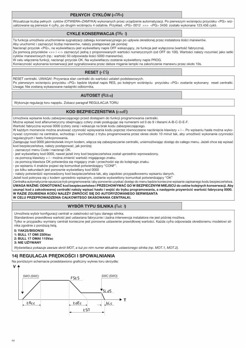
66
PEŁNYCH CYKLÓW (Nman)Wizualizuje liczbę pełnych cyklów (OTWIERA+ZAMYKA) wykonanych przez urządzenie automatyzacji. Po pierwszym wcisnięciu przycisku <PG> wiz-ualizowane są pierwsze 4 cyfry, po drugim wciśnięciu 4 ostatnie. Przykład. <PG> 0012 >>> <PG> 3456: zostało wykonane 123.456 cykli.
CYKLE KONSERWACJA (maci)Ta funkcja umożliwia uruchomienie sygnalizacji zabiegu konserwacyjnego po upływie określonej przez instalatora ilości manewrów.Aby uruchomić i zaznaczyć liczbę manewrów, należy postępować jak poniżej:Nacisnąć przycisk <PG>, na wyświetlaczu jest wyświetlany napis OFF wskazujący, że funkcja jest wyłączona (wartość fabryczna). Za pomocą przycisków <+> i <-> zaznaczyć jedną z proponowanych wartości numerycznych (od OFF do 100). Wartości należy rozumieć jako setki cyklów manewrowych (np.: wartość 50 odpowiada ilości 5000 manewrów).W celu włączenia funkcji, nacisnąć przycisk OK. Na wyświetlaczu zostanie wyświetlony napis PROG.Konieczność wykonania konserwacji jest sygnalizowana przez dalsze miganie lampki na zakończenie manewru przez około 10s.
RESET (RES)RESET centralki. UWAGA!: Przywraca stan centralki do wartości ustaleń podstawowych.Po pierwszym wcisnięciu przycisku <PG> będzie błyskał napis RES, po kolejnym wciśnięciu przycisku <PG> zostanie wykonany reset centralki. Uwaga: Nie zostaną wykasowane nadajniki odbiornika.
AUTOSET (AUTO)
Wykonuje regulację toru napędu. Zobacz paragraf REGULACJA TORU
KOD BEZPIECZEŃSTWA (code)Umożliwia wpisanie kodu zabezpieczającego przed dostępem do funkcji programowania centralki.Można wpisać kod alfanumeryczny obejmujący cztery znaki posługując się numerami od 0 do 9 i literami A-B-C-D-E-F.Wartość fabryczna wynosi 0000 (cztery zera) i wskazuje na brak kodu zabezpieczającego.W każdym momencie można anulować czynność wpisywania kodu poprzez równoczesne naciśnięcie klawiszy + i -. Po wpisaniu hasła można wyko-nywać czynności na centralce, wchodząc i wychodząc z trybu programowania przez okres około 10 minut tak, aby umożliwić wykonanie czynności regulacyjnych i testu funkcjonowania.Zastępując kod 0000 jakimkolwiek innym kodem, włącza się zabezpieczenie centralki, uniemożliwiając dostęp do całego menu. Jeżeli chce się wpisać kod bezpieczeństwa, należy postępować, jak poniżej:- zaznaczyć menu Code i nacisnąć OK.- jest wyświetlany kod 0000, nawet jeżeli inny kod bezpieczeństwa został uprzednio wprowadzony.- za pomocą klawiszy + i - można zmienić wartość migającego znaku.- za pomocą klawisza OK potwierdza się migający znak i przechodzi się do kolejnego znaku.- po wpisaniu 4 znaków pojawi się komunikat potwierdzający “CONF”.- po kilku sekundach jest ponownie wyświetlany kod 0000- należy potwierdzić wprowadzony kod bezpieczeństwa tak, aby zapobiec przypadkowemu wpisaniu danych.Jeżeli kod pokrywa się z kodem uprzednio wpisanym, zostanie wyświetlony komunikat potwierdzający “OK”Centralka automatycznie opuszcza tryb programowania i aby ponownie uzyskać dostęp do menu będzie konieczne wpisanie zapisanego kodu bezpieczeństwa.UWAGA WAŻNE: ODNOTOWAĆ kod bezpieczeństwa i PRZECHOWYWAĆ GO W BEZPIECZNYM MIEJSCU do celów kolejnych konserwacji. Aby usunąć kod z zakodowanej centralki należy wpisać hasło i wejść do trybu programowania, a następnie przywrócić wartość fabryczną 0000.W RAZIE ZGUBIENIA KODU NALEŻY ZWRÓCIĆ SIĘ DO AUTORYZOWANEGO SERWISANTA W CELU PRZEPROWADZENIA CAŁKOWITEGO SKASOWANIA CENTRALKI.
WYBÓR TYPU SILNIKA (MOT1)
Umożliwia wybór konfiguracji centrali w zależności od typu danego silnika.Standardowo prawidłowa wartość jest ustawiana fabrycznie i żadna interwencja instalatora nie jest później możliwa.Tylko w przypadku wymiany centrali konieczne jest ponowne ustawienie prawidłowej wartości. Każda cyfra odpowiada określonemu modelowi sil-nika zgodnie z poniższą listą.
0: YAK25/BISON351: BULL 17 OMI 230Vac2: BULL 17 OMAI 115Vac3: NIE UŻYWANY
Wyświetlacz pokazuje zawsze skrót MOT, a tuż po nim numer aktualnie ustawionego silnika (np. MOT.1, MOT.2).
14) REGULACJA PRĘDKOŚCI I SPOWALNIANIANa poniższym schemacie przedstawiono graficzny wykres toru skrzydła:
V
T
FSTS
slds
BLcTAcc Tdec
TSM
SWO (SWC) SWC (SWO)
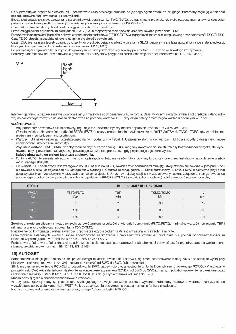
67
Oś V przedstawia prędkość skrzydła, oś T przedstawia czas przebiegu skrzydła od jednego ogranicznika do drugiego. Parametry regulują w ten sam sposób zarówno fazę otwierania jak i zamykania.Biorąc pod uwagę skrzydło zatrzymane na jakimkolwiek ograniczniku SWO (SWC), po naciśnięciu przycisku skrzydło rozpoczyna manewr w celu osią-gnięcia standardowej prędkości funkcjonowania, regulowanej przez parametr FSTSO/FSTSC. Czas TACC określa jak szybko skrzydło osiągnie standardową prędkość.Przed osiągnięciem ogranicznika zatrzymania SWC (SWO) rozpoczyna fazę spowalniania regulowaną przez czas TSM.Faza spowalniania powoduje przejście skrzydła z prędkości standardowej (FSTSO/FSTSC) na prędkość spowalniania regulowaną przez parametr SLDSO/SLDSC.Czas TDEC określa jak szybko skrzydło osiągnie prędkość spowalniania.Czas TDEC jest czasem teoretycznym, gdyż jak tylko prędkość osiąga wartość wpisaną na SLDS rozpoczyna się faza spowalniania wg stałej prędkości, która jest kontynuowana do przesłonięcia ogranicznika SWC (SWO).Po przesłonięciu ogranicznika, skrzydło dalej kontynuuje ruch przez czas regulowany parametrem BLC aż do całkowitego zatrzymania.Poniższy schemat zawiera przedstawienie graficzne toru skrzydła w przypadku zadziałania wejścia bezpieczeństwa (STOP/PHOT/BAR):
V
T
FSTo/fstc
sldo/SldC
BLo/blcTAcc Tdec
TSMo/tsmc
SWO (SWC) SWC (SWO)
V
Ttbr
stopphotbar
Interwencja wejścia bezpieczeństwa powoduje natychmiastowe spowolnienie ruchu skrzydła. Czas, w którym skrzydło zwalnia od prędkości standardo-wej do całkowitego zatrzymania można dostosować za pomocą wartości TBR, przy czym należy przestrzegać wartości podanych w Tabeli 1.
WAŻNE UWAGI:- Aby parametry prawidłowo funkcjonowały, regulacja toru powinna być wykonana poprawnie (zobacz REGULACJA TORU).- W razie zwiększenia wartości prędkości FSTSo (FSTSc), należy proporcjonalnie zwiększyć wartości TSMo(TSMc), TACC i TDEC, aby zapobiec na-
prężeniom mechanicznym motoreduktora.- Wartość TBR należy ustawiać, przestrzegając danych podanych w Tabeli 1. Ustawienie zbyt niskiej wartości TBR dla skrzydła o dużej inercji może
spowodować uszkodzenie automatyki. Zbyt mała wartość TSM0(TSMc), w połączeniu ze zbyt dużą wartością TDEC mogłaby doprowadzić, na skutek siły bezwładności skrzydła, do wyze-
rowania fazy spowalniania SLDo(SLDc), powodując włączenie ogranicznika, gdy prędkość jest jeszcze wysoka. Należy obowiązkowo unikać tego typu zachowania.- Funkcja AUTO nie zmienia fabrycznych wartości opisanych wyżej parametrów, które powinny być ustawione przez instalatora na podstawie właści-
wości danego skrzydła.- Do wejścia BAR podłączony jest szeregowo do COSTA (lub do COST) również styk normalnie zamknięty, który otwiera się zawsze w przypadku od-
blokowania silnika lub zdjęcia osłony. Dlatego też w sytuacji 1. Centrala pod napięciem, 2. Silnik zatrzymany, 3. SWO i SWC nieaktywne (czyli silnik poza wyłącznikiem krańcowym), w przypadku aktywacji wejścia BAR i ponownej aktywacji (silnik zablokowany i osłona załączona, stan gotowości do ponownego uruchomienia), po wydaniu kolejnego polecenia PP/OPEN/CLOSE (również drogą radiową) należy wymusić manewr powolny.
STÓŁ 1 BULL 17 OMI / BULL 17 OMAI
WAGAKg
FSTO/FSTCMax
TBRMin
TSMO/TSMCMin
Vm/1'
1700 85 2 30 17
1000 100 3 35 20
500 120 4 50 24
Zgodnie z modelem siłownika i wagą skrzydła ustawić wartość prędkości otwierania i zamykania (FSTO/FSTC), minimalną wartość hamowania TBR i minimalną wartość odległości spowalniania TSMO/TMC.Niezależnie od kombinacji uzyskana wartość prędkości skrzydła (kolumna V) jest wyrażona w metrach na minutę.Przekroczenie zalecanych wartości może spowodować uszkodzenia i nieprawidłowe działanie. Producent nie ponosi odpowiedzialności za niewłaściwą konfiguracje wartości FSTO/FSTC/TBR/TSMO/TSMC.Podane wartości to wartości orientacyjne, odnoszące się do instalacji standardowej. Instalator musi upewnić się, że przestrzegane są wartości gra-niczne przewidziane w normach EN 12453, EN 12445).
15) AUTOSETSamonauczanie biegu jest konieczne dla prawidłowego działania zwalniania i odbywa się przez zastosowanie funkcji AUTO opisanej powyżej przy pierwszym pełnym manewrze (czyli wykonanym bez przerw) od SWO do SWC (lub odwrotnie).Silnik uruchamia się w trybie POWOLI w poszukiwaniu SWO, zatrzymuje się, a następnie zmienia kierunek ruchu wykonując POWOLNY manewr w poszukiwaniu SWC (określanie toru). Następnie wykonuje pierwszy manewr SZYBKI od SWC do SWO (zmiany, prędkości, spowolnienia określone przez ustawione parametry TSMo/TSMc/FSTo/FSTc/SLDo/SLDc) i drugi szybki manewr od SWO do SWC.Można później ręcznie zmienić wzmiankowane wartości.W przypadku ręcznej modyfikacji parametru wymagającego nowego ustawienia centrala wykonuje kompletny manewr otwierania i zamykania. Na wyświetlaczu pojawia się komunikat „PRG”. Po jego zakończeniu przywrócone zostają normalne funkcje urządzenia.Nie jest możliwe wykonanie ustawienia automatycznego Autoset z logiką HTR:ON
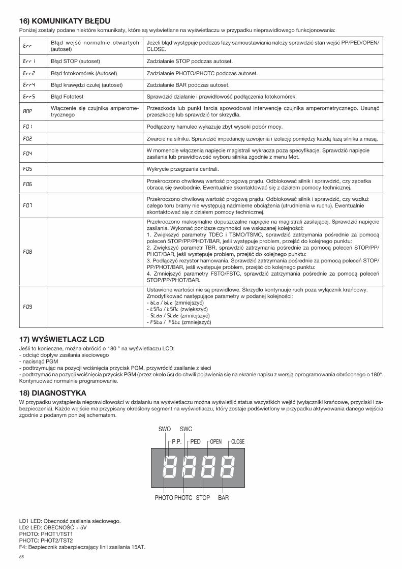
68
16) KOMUNIKATY BŁĘDUPoniżej zostały podane niektóre komunikaty, które są wyświetlane na wyświetlaczu w przypadku nieprawidłowego funkcjonowania:
errBłąd wejść normalnie otwartych (autoset)
Jeżeli błąd występuje podczas fazy samoustawiania należy sprawdzić stan wejść PP/PED/OPEN/CLOSE.
Err1 Błąd STOP (autoset) Zadziałanie STOP podczas autoset.
Err2 Błąd fotokomórek (Autoset) Zadziałanie PHOTO/PHOTC podczas autoset.
Err4 Błąd krawędzi czułej (autoset) Zadziałanie BAR podczas autoset.
Err5 Błąd Fototest Sprawdzić działanie i prawidłowość podłączenia fotokomórek.
ampWłączenie się czujnika amperome-trycznego
Przeszkoda lub punkt tarcia spowodował interwencję czujnika amperometrycznego. Usunąć przeszkodę lub sprawdzić tor skrzydła.
F01 Podłączony hamulec wykazuje zbyt wysoki pobór mocy.
F02 Zwarcie na silniku. Sprawdzić impedancję uzwojenia i izolację pomiędzy każdą fazą silnika a masą.
F04W momencie włączenia napięcie magistrali wykracza poza specyfikacje. Sprawdzić napięcie zasilania lub prawidłowość wyboru silnika zgodnie z menu Mot.
F05 Wykrycie przegrzania centrali.
F06Przekroczono chwilową wartość progową prądu. Odblokować silnik i sprawdzić, czy zębatka obraca się swobodnie. Ewentualnie skontaktować się z działem pomocy technicznej.
F07
Przekroczono chwilową wartość progową prądu. Odblokować silnik i sprawdzić, czy wzdłuż całego toru bramy nie występują nadmierne obciążenia (utrudnienia w ruchu). Ewentualnie skontaktować się z działem pomocy technicznej.
F08
Przekroczono maksymalne dopuszczalne napięcie na magistrali zasilającej. Sprawdzić napięcie zasilania. Wykonać poniższe czynności we wskazanej kolejności:1. Zwiększyć parametry TDEC i TSMO/TSMC, sprawdzić zatrzymania pośrednie za pomocą poleceń STOP/PP/PHOT/BAR, jeśli występuje problem, przejść do kolejnego punktu:2. Zwiększyć parametr TBR, sprawdzić zatrzymania pośrednie za pomocą poleceń STOP/PP/PHOT/BAR, jeśli występuje problem, przejść do kolejnego punktu:3. Podłączyć rezystor hamowania. Sprawdzić zatrzymania pośrednie za pomocą poleceń STOP/PP/PHOT/BAR, jeśli występuje problem, przejść do kolejnego punktu:4. Zmniejszyć parametry FSTO/FSTC, sprawdzić zatrzymania pośrednie za pomocą poleceń STOP/PP/PHOT/BAR.
F09
Ustawione wartości nie są prawidłowe. Skrzydło kontynuuje ruch poza wyłącznik krańcowy.Zmodyfikować następujące parametry w podanej kolejności:- blo / blc (zmniejszyć)- tsmo / tsmc (zwiększyć)- sldo / sldc (zmniejszyć)- fsto / fstc (zmniejszyć)
17) WYŚWIETLACZ LCDJeśli to konieczne, można obrócić o 180 ° na wyświetlaczu LCD:- odciąć dopływ zasilania sieciowego- nacisnąć PGM- podtrzymując na pozycji wciśnięcia przycisk PGM, przywrócić zasilanie z sieci- podtrzymać na pozycji wciśnięcia przycisk PGM (przez około 5s) do chwili pojawienia się na ekranie napisu z wersją oprogramowania obróconego o 180°. Kontynuować normalnie programowanie.
18) DIAGNOSTYKAW przypadku wystąpienia nieprawidłowości w działaniu na wyświetlaczu można wyświetlić status wszystkich wejść (wyłączniki krańcowe, przyciski i za-bezpieczenia). Każde wejście ma przypisany określony segment na wyświetlaczu, który zostaje podświetlony w przypadku aktywowania danego wejścia zgodnie z podanym poniżej schematem.
PHOTO
SWC
STOP
SWO
PHOTC BAR
P.P. PED OPEN CLOSE
LD1 LED: Obecność zasilania sieciowego.LD2 LED: OBECNOŚĆ + 5VPHOTO: PHOT1/TST1PHOTC: PHOT2/TST2F4: Bezpiecznik zabezpieczający linii zasilania 15AT.
69
19) KONSERWACJANiżej zamieszczona tabela służy do odnotowywania prac konserwacyjnych, ulepszeń lub napraw wykonanych przez wyspecjalizowanego technika.
Data _ _ _ _ _ _ _ _ _ _ _ _ _ _ _ _ _ _ _ _ _ _ _ _ _ _ _ _ _ _ _ _ Podpis technika _ _ _ _ _ _ _ _ _ _ _ _ _ _ _ _ _ _ _ _ _ _ _ _ _ _ Pieczątka
Opis czynności
_ _ _ _ _ _ _ _ _ _ _ _ _ _ _ _ _ _ _ _ _ _ _ _ _ _ _ _ _ _ _ _ _ _ _ _ _ _ _ _ _ _ _ _ _ _ _ _ _ _ _ _ _ _ _ _ _ _ _ _ _ _ _ _ _ _ _ _ _ _ _ _ _
_ _ _ _ _ _ _ _ _ _ _ _ _ _ _ _ _ _ _ _ _ _ _ _ _ _ _ _ _ _ _ _ _ _ _ _ _ _ _ _ _ _ _ _ _ _ _ _ _ _ _ _ _ _ _ _ _ _ _ _ _ _ _ _ _ _ _ _ _ _ _ _ _
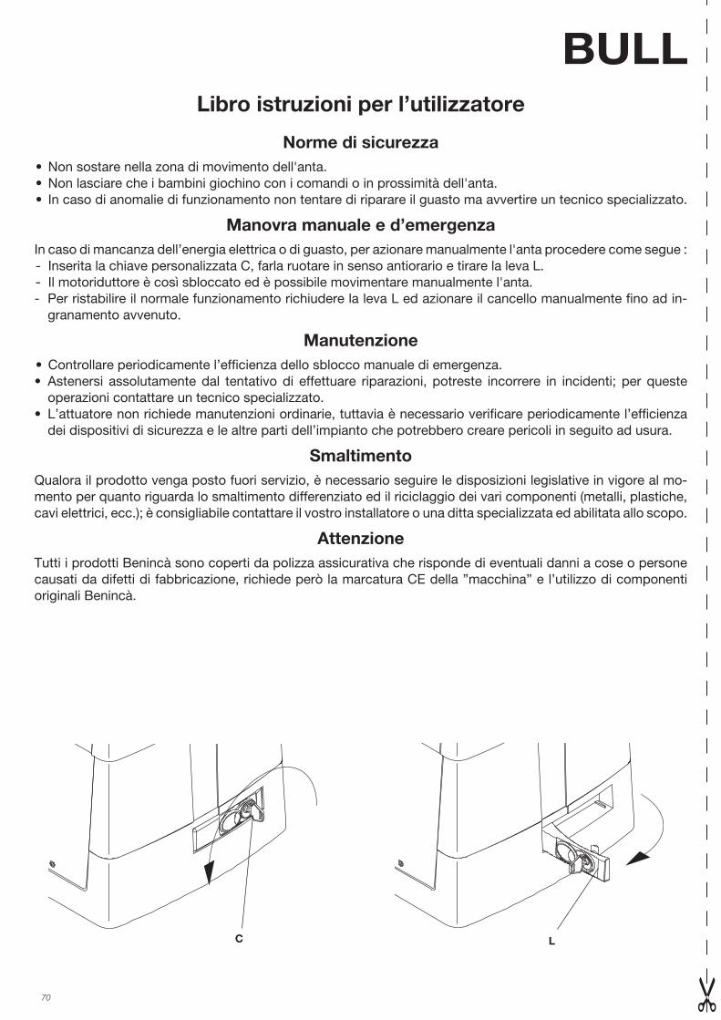
70
Norme di sicurezza• Non sostare nella zona di movimento dell'anta.• Non lasciare che i bambini giochino con i comandi o in prossimità dell'anta.• In caso di anomalie di funzionamento non tentare di riparare il guasto ma avvertire un tecnico specializzato.
Manovra manuale e d’emergenzaIn caso di mancanza dell’energia elettrica o di guasto, per azionare manualmente l'anta procedere come segue : - Inserita la chiave personalizzata C, farla ruotare in senso antiorario e tirare la leva L.- Il motoriduttore è così sbloccato ed è possibile movimentare manualmente l'anta.- Per ristabilire il normale funzionamento richiudere la leva L ed azionare il cancello manualmente fino ad in-
granamento avvenuto.
Manutenzione• Controllare periodicamente l’efficienza dello sblocco manuale di emergenza.• Astenersi assolutamente dal tentativo di effettuare riparazioni, potreste incorrere in incidenti; per queste
operazioni contattare un tecnico specializzato.• L’attuatore non richiede manutenzioni ordinarie, tuttavia è necessario verificare periodicamente l’efficienza
dei dispositivi di sicurezza e le altre parti dell’impianto che potrebbero creare pericoli in seguito ad usura.
SmaltimentoQualora il prodotto venga posto fuori servizio, è necessario seguire le disposizioni legislative in vigore al mo-mento per quanto riguarda lo smaltimento differenziato ed il riciclaggio dei vari componenti (metalli, plastiche, cavi elettrici, ecc.); è consigliabile contattare il vostro installatore o una ditta specializzata ed abilitata allo scopo.
AttenzioneTutti i prodotti Benincà sono coperti da polizza assicurativa che risponde di eventuali danni a cose o persone causati da difetti di fabbricazione, richiede però la marcatura CE della ”macchina” e l’utilizzo di componenti originali Benincà.
BULLLibro istruzioni per l’utilizzatore
C L
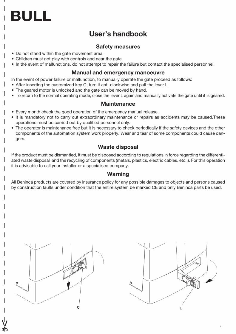
71
BULLUser’s handbook
Safety measures• Do not stand within the gate movement area.• Children must not play with controls and near the gate.• In the event of malfunctions, do not attempt to repair the failure but contact the specialised personnel.
Manual and emergency manoeuvre In the event of power failure or malfunction, to manually operate the gate proceed as follows:• After inserting the customized key C, turn it anti-clockwise and pull the lever L.• The geared motor is unlocked and the gate can be moved by hand.• To return to the normal operating mode, close the lever L again and manually activate the gate until it is geared.
Maintenance• Every month check the good operation of the emergency manual release.• It is mandatory not to carry out extraordinary maintenance or repairs as accidents may be caused.These
operations must be carried out by qualified personnel only.• The operator is maintenance free but it is necessary to check periodically if the safety devices and the other
components of the automation system work properly. Wear and tear of some components could cause dan-gers.
Waste disposalIf the product must be dismantled, it must be disposed according to regulations in force regarding the differenti-ated waste disposal and the recycling of components (metals, plastics, electric cables, etc..). For this operation it is advisable to call your installer or a specialised company.
WarningAll Benincá products are covered by insurance policy for any possible damages to objects and persons caused by construction faults under condition that the entire system be marked CE and only Benincá parts be used.
C L
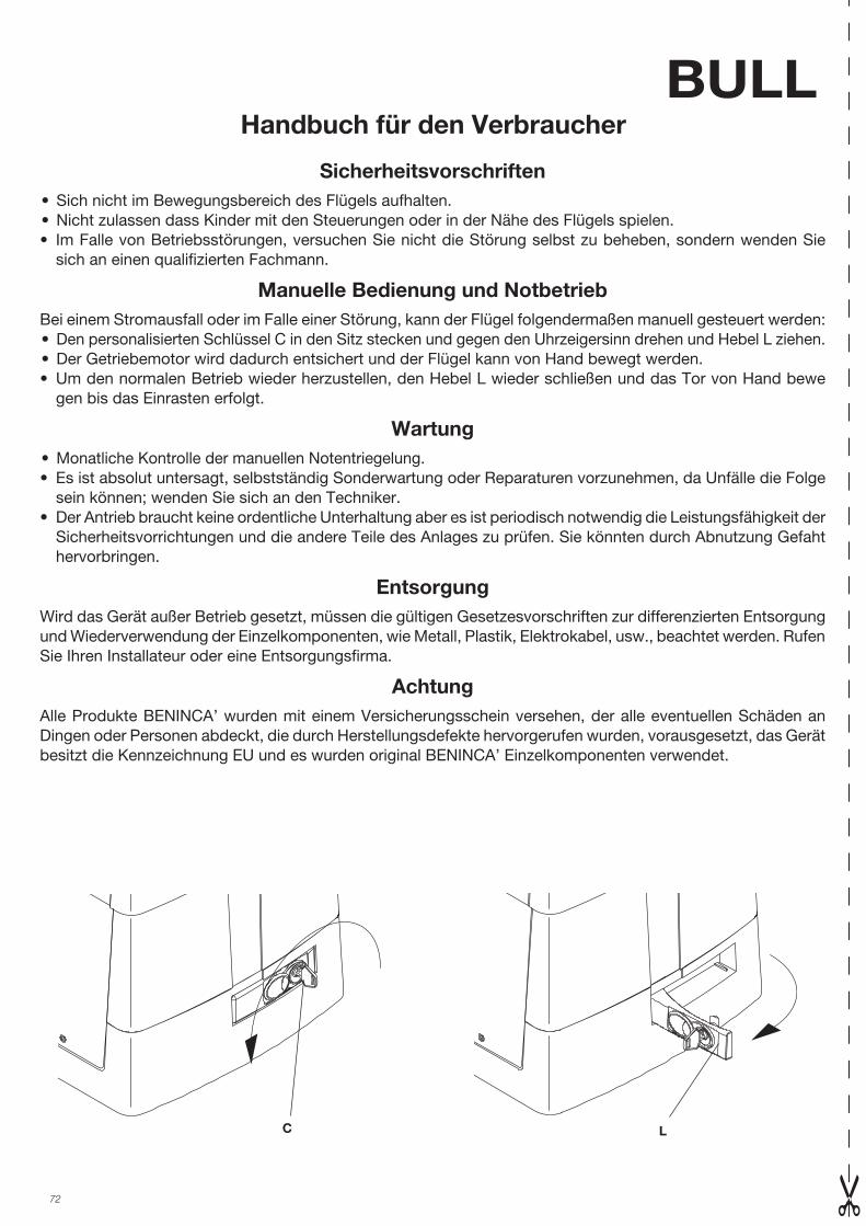
72
BULLHandbuch für den Verbraucher
Sicherheitsvorschriften • Sich nicht im Bewegungsbereich des Flügels aufhalten.• Nicht zulassen dass Kinder mit den Steuerungen oder in der Nähe des Flügels spielen.• Im Falle von Betriebsstörungen, versuchen Sie nicht die Störung selbst zu beheben, sondern wenden Sie
sich an einen qualifizierten Fachmann.
Manuelle Bedienung und NotbetriebBei einem Stromausfall oder im Falle einer Störung, kann der Flügel folgendermaßen manuell gesteuert werden: • Den personalisierten Schlüssel C in den Sitz stecken und gegen den Uhrzeigersinn drehen und Hebel L ziehen.• Der Getriebemotor wird dadurch entsichert und der Flügel kann von Hand bewegt werden.• Um den normalen Betrieb wieder herzustellen, den Hebel L wieder schließen und das Tor von Hand bewe
gen bis das Einrasten erfolgt.
Wartung• Monatliche Kontrolle der manuellen Notentriegelung.• Es ist absolut untersagt, selbstständig Sonderwartung oder Reparaturen vorzunehmen, da Unfälle die Folge
sein können; wenden Sie sich an den Techniker.• Der Antrieb braucht keine ordentliche Unterhaltung aber es ist periodisch notwendig die Leistungsfähigkeit der
Sicherheitsvorrichtungen und die andere Teile des Anlages zu prüfen. Sie könnten durch Abnutzung Gefaht hervorbringen.
EntsorgungWird das Gerät außer Betrieb gesetzt, müssen die gültigen Gesetzesvorschriften zur differenzierten Entsorgung und Wiederverwendung der Einzelkomponenten, wie Metall, Plastik, Elektrokabel, usw., beachtet werden. Rufen Sie Ihren Installateur oder eine Entsorgungsfirma.
AchtungAlle Produkte BENINCA’ wurden mit einem Versicherungsschein versehen, der alle eventuellen Schäden an Dingen oder Personen abdeckt, die durch Herstellungsdefekte hervorgerufen wurden, vorausgesetzt, das Gerät besitzt die Kennzeichnung EU und es wurden original BENINCA’ Einzelkomponenten verwendet.
C L
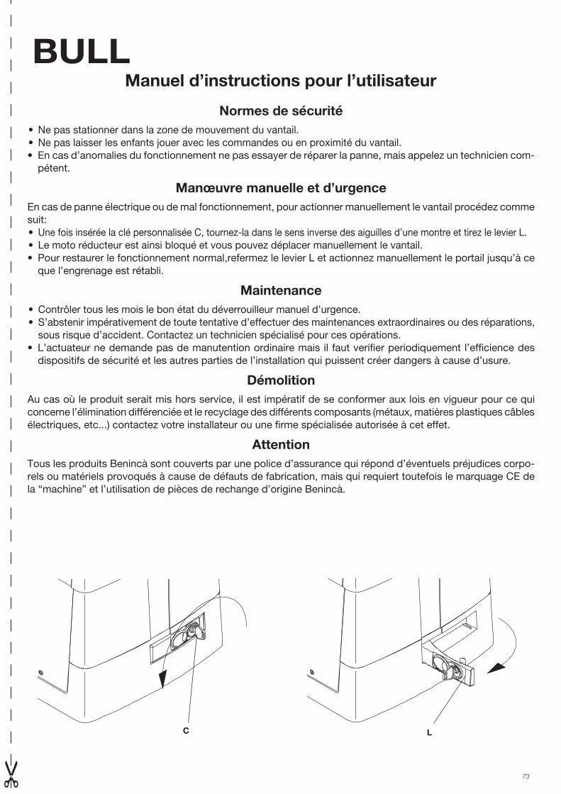
73
BULLManuel d’instructions pour l’utilisateur
Normes de sécurité• Ne pas stationner dans la zone de mouvement du vantail.• Ne pas laisser les enfants jouer avec les commandes ou en proximité du vantail.• En cas d’anomalies du fonctionnement ne pas essayer de réparer la panne, mais appelez un technicien com-
pétent.
Manœuvre manuelle et d’urgenceEn cas de panne électrique ou de mal fonctionnement, pour actionner manuellement le vantail procédez comme suit: • Une fois insérée la clé personnalisée C, tournez-la dans le sens inverse des aiguilles d’une montre et tirez le levier L.• Le moto réducteur est ainsi bloqué et vous pouvez déplacer manuellement le vantail.• Pour restaurer le fonctionnement normal,refermez le levier L et actionnez manuellement le portail jusqu’à ce
que l’engrenage est rétabli.
Maintenance• Contrôler tous les mois le bon état du déverrouilleur manuel d’urgence.• S’abstenir impérativement de toute tentative d’effectuer des maintenances extraordinaires ou des réparations, sous risque d’accident. Contactez un technicien spécialisé pour ces opérations.• L’actuateur ne demande pas de manutention ordinaire mais il faut verifier periodiquement l’efficience des
dispositifs de sécurité et les autres parties de l’installation qui puissent créer dangers à cause d’usure.
DémolitionAu cas où le produit serait mis hors service, il est impératif de se conformer aux lois en vigueur pour ce qui concerne l’élimination différenciée et le recyclage des différents composants (métaux, matières plastiques câbles électriques, etc...) contactez votre installateur ou une firme spécialisée autorisée à cet effet.
AttentionTous les produits Benincà sont couverts par une police d’assurance qui répond d’éventuels préjudices corpo-rels ou matériels provoqués à cause de défauts de fabrication, mais qui requiert toutefois le marquage CE de la “machine” et l’utilisation de pièces de rechange d’origine Benincà.
C L
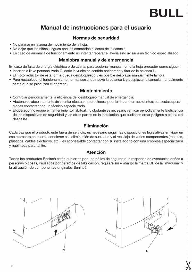
74
BULLManual de instrucciones para el usuario
Normas de seguridad• No pararse en la zona de movimiento de la hoja.• No dejar que los niños jueguen con los comandos ni cerca de la cancela.• En caso de anomalía de funcionamiento no intentar reparar el avería sino avisar a un técnico especializado.
Maniobra manual y de emergenciaEn caso de falta de energía eléctrica o de avería, para accionar manualmente la hoja proceder como sigue : • Insertar la llave personalizada C, darle la vuelta en sentido antihorario y tirar de la palanca L.• El motorreductor de esta forma queda desbloqueado y es posible desplazar manualmente la hoja.• Para restablecer el funcionamiento normal cerrar de nuevo la palanca L y desplazar la cancela manualmente
hasta que se produzca el engrane.
Mantenimiento• Controlar periódicamente la eficiencia del desbloqueo manual de emergencia.• Abstenerse absolutamente de intentar efectuar reparaciones, podrían incurrir en accidentes; para estas opera ciones contactar con un técnico especializado.• El operador no requiere mantenimiento habitual, no obstante es necesario verificar periódicamente la eficiencia
de los dispositivos de seguridad y las otras partes de la instalación que pudiesen crear peligros a causa del desgaste.
EliminaciónCada vez que el producto esté fuera de servicio, es necesario seguir las disposiciones legislativas en vigor en ese momento en cuanto concierne a la eliminación de suciedad y al reciclaje de varios componentes (metales, plásticos, cables eléctricos, etc.), es aconsejable contactar con su instalador o con una empresa especializada y habilitada para tal fin.
AtenciónTodos los productos Benincà están cubiertos por una póliza de seguros que responde de eventuales daños a personas o cosas, causados por defectos de fabricación, requiere sin embargo la marca CE de la ”máquina” y la utilización de componentes originales Benincà.
C L
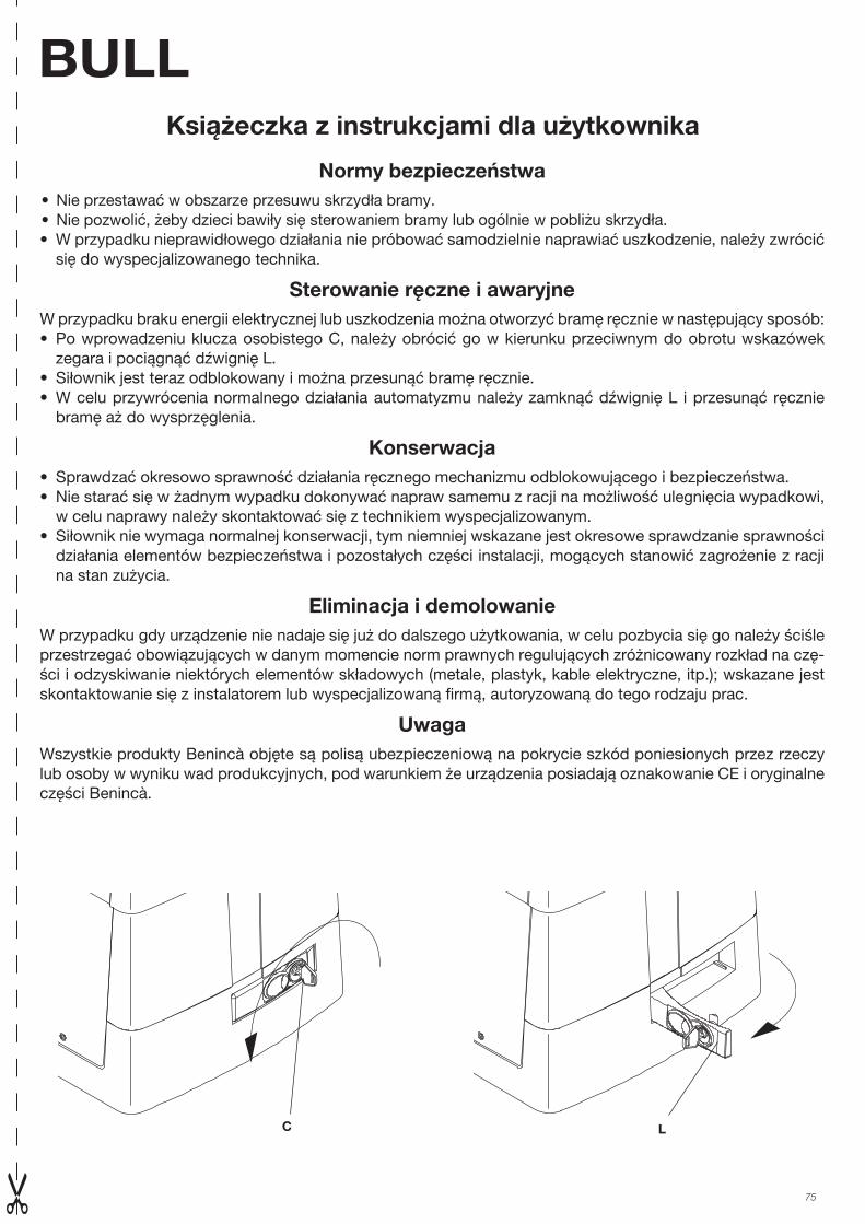
75
BULLKsiążeczka z instrukcjami dla użytkownika
Normy bezpieczeństwa• Nie przestawać w obszarze przesuwu skrzydła bramy.• Nie pozwolić, żeby dzieci bawiły się sterowaniem bramy lub ogólnie w pobliżu skrzydła.• W przypadku nieprawidłowego działania nie próbować samodzielnie naprawiać uszkodzenie, należy zwrócić
się do wyspecjalizowanego technika.
Sterowanie ręczne i awaryjneW przypadku braku energii elektrycznej lub uszkodzenia można otworzyć bramę ręcznie w następujący sposób:• Po wprowadzeniu klucza osobistego C, należy obrócić go w kierunku przeciwnym do obrotu wskazówek
zegara i pociągnąć dźwignię L.• Siłownik jest teraz odblokowany i można przesunąć bramę ręcznie.• W celu przywrócenia normalnego działania automatyzmu należy zamknąć dźwignię L i przesunąć ręcznie
bramę aż do wysprzęglenia.
Konserwacja• Sprawdzać okresowo sprawność działania ręcznego mechanizmu odblokowującego i bezpieczeństwa.• Nie starać się w żadnym wypadku dokonywać napraw samemu z racji na możliwość ulegnięcia wypadkowi,
w celu naprawy należy skontaktować się z technikiem wyspecjalizowanym.• Siłownik nie wymaga normalnej konserwacji, tym niemniej wskazane jest okresowe sprawdzanie sprawności
działania elementów bezpieczeństwa i pozostałych części instalacji, mogących stanowić zagrożenie z racji na stan zużycia.
Eliminacja i demolowanieW przypadku gdy urządzenie nie nadaje się już do dalszego użytkowania, w celu pozbycia się go należy ściśle przestrzegać obowiązujących w danym momencie norm prawnych regulujących zróżnicowany rozkład na czę-ści i odzyskiwanie niektórych elementów składowych (metale, plastyk, kable elektryczne, itp.); wskazane jest skontaktowanie się z instalatorem lub wyspecjalizowaną firmą, autoryzowaną do tego rodzaju prac.
UwagaWszystkie produkty Benincà objęte są polisą ubezpieczeniową na pokrycie szkód poniesionych przez rzeczy lub osoby w wyniku wad produkcyjnych, pod warunkiem że urządzenia posiadają oznakowanie CE i oryginalne części Benincà.
C L
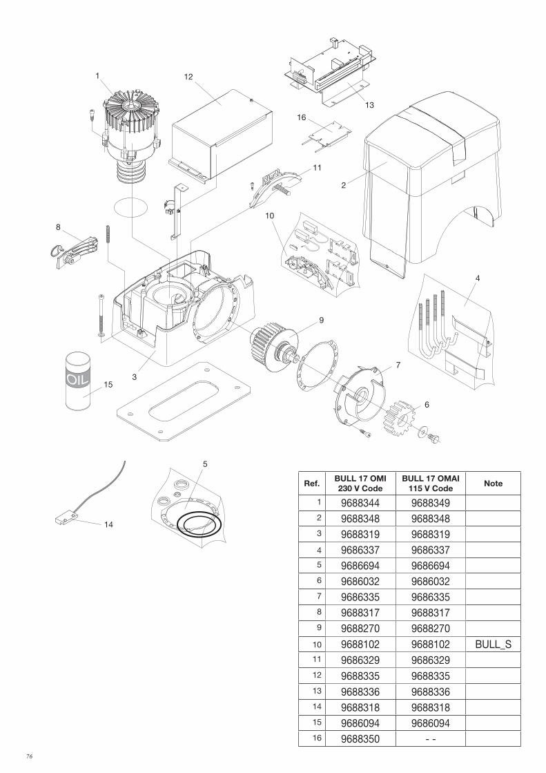
76
11
121
8
9
3
2
7
6
4
10
13
15
5
14
16
Ref.BULL 17 OMI230 V Code
BULL 17 OMAI115 V Code
Note
1 9688344 96883492 9688348 96883483 9688319 96883194 9686337 96863375 9686694 96866946 9686032 96860327 9686335 96863358 9688317 96883179 9688270 9688270
10 9688102 9688102 BULL_S11 9686329 968632912 9688335 968833513 9688336 968833614 9688318 968831815 9686094 968609416 9688350 - -
77
Dichiarazione di Conformità UE (DoC)
Nome del produttore: Automatismi Benincà SpA Indirizzo: Via Capitello, 45 - 36066 Sandrigo (VI) - ItaliaTelefono: +39 0444 751030 Indirizzo e-mail: [email protected] autorizzata a costruire la documentazione tecnica: Automatismi Benincà SpA
Dichiara che il documento è rilasciato sotto la propria responsabilità e appartiene al seguente prodotto:Tipo di prodotto: Attuatore elettromeccanico per cancelli scorrevoliModello/Tipo: BULL 17 OMI Accessori: N/A
Il prodotto sopraindicato risulta conforme alle disposizioni imposte dale seguenti direttive:Direttiva 2014/53/EUDirettiva 2011/65/EUDirettiva 2006/42/CE
Sono state applicate le norme armonizzate e le specifiche tecniche descritte di seguito:ETSI EN 300 220-1 V3.1.1ETSI EN 300 220-2 V3.1.1ETSI EN 301 489-1 V2.1.1ETSI EN 301 489-3 V2.1.1EN 50950-1:2006 + A11:2009 + A1:2010 + A12:2011 + AC:2011 + A2:2013EN 61000-6-2:2005, EN 61000-6-3:2007 + A1:2011EN 60335-1:2012 + A11:2014; EN 60335-2-103:201550581-2012EN 13241-1:2003EN 12445:2002, EN 12453:2002, EN 12978:2003 (se applicabile).
Il Certificato di Conformità di questo documento corrisponde all'ultima revisione disponibile al momento della stampa e può risultare differente per esigenze editoriali dall'originale disponibile presso il produttore.
Benincà Luigi, Responsabile legale.Sandrigo, 18/04/2018.
UE Declaration of Conformity (DoC)Manufacturer's name: Automatismi Benincà SpA Address: Via Capitello, 45 - 36066 Sandrigo (VI) - ItaliaTelephone: +39 0444 751030 Email address: [email protected] authorised to draft the technical documentation: Automatismi Benincà SpA
Declare that the DOC is issued under our sole responsibility and belongs to the following product:
Product type: Electromechanical motor for sliding gatesModel/type: BULL 17 OMI Accessories: N/A
The object of the declaration described above is in conformity with the relevant Union harmonization legislation:Directive 2014/53/EUDirective 2011/65/EUDirective 2006/42/CE
The following harmonized standards and technical specifications have been applied:ETSI EN 300 220-1 V3.1.1ETSI EN 300 220-2 V3.1.1ETSI EN 301 489-1 V2.1.1ETSI EN 301 489-3 V2.1.1EN 50950-1:2006 + A11:2009 + A1:2010 + A12:2011 + AC:2011 + A2:2013EN 61000-6-2:2005, EN 61000-6-3:2007 + A1:2011EN 60335-1:2012 + A11:2014; EN 60335-2-103:201550581-2012EN 13241-1:2003EN 12445:2002, EN 12453:2002, EN 12978:2003 (if applicable).
The certificate of conformity in this document corresponds to the last review available at the time of printing and could differ for editorial requirements from the original available from the manufacturer.
Benincà Luigi, Legal Officer.Sandrigo, 18/04/2018.
EG-Konformitätserklärung (DoC)
Name des Herstellers: Automatismi Benincà SpAAdresse: Via Capitello, 45 - 36066 Sandrigo (VI) - Italia Telefon: +39 0444 751030 E-Mail-Adresse: [email protected] Erstellung der technischen Dokumentation berechtigte Person: Automatismi Benincà SpA
Erklärt, dass das Dokument unter alleiniger Verantwortung herausgegeben wurde und zu dem folgenden Produkt ge-hört:Produkttypus: Automation für SchiebetoreModell/Typus: BULL 17 OMI Zubehör: N/ADas oben genannte Produkt stimmt mit den Vorschriften der folgenden Richtlinien überein:Direttiva 2014/53/EUDirettiva 2011/65/EUDirettiva 2006/42/CE
Die harmonisierten Normen und technischen Spezifikationen, die unten beschrieben werden, wurden angewandt:ETSI EN 300 220-1 V3.1.1ETSI EN 300 220-2 V3.1.1ETSI EN 301 489-1 V2.1.1ETSI EN 301 489-3 V2.1.1EN 50950-1:2006 + A11:2009 + A1:2010 + A12:2011 + AC:2011 + A2:2013EN 61000-6-2:2005, EN 61000-6-3:2007 + A1:2011EN 60335-1:2012 + A11:2014; EN 60335-2-103:201550581-2012EN 13241-1:2003EN 12445:2002, EN 12453:2002, EN 12978:2003 (Falls zutreffend).
Die in diesem Dokument vorliegende Konformitätserklärung entspricht der neuesten zum Druckzeitpunkt erhältlichen Revision und könnte aufgrund von verlegerischen Gründen vom beim Hersteller erhältlichen Original abweichen.
Benincà Luigi, Rechtsvertreter.Sandrigo, 18/04/2018.
Déclaration CE de conformité (DoC)Nom du producteur : Automatismi Benincà SpAAdresse : Via Capitello, 45 - 36066 Sandrigo (VI) - Italia Téléphone : +39 0444 751030 Adresse e-mail: [email protected] Personne autorisée à construire la documentation technique : Automatismi Benincà SpA
Nous déclarons que le document est délivré sous notre propre responsabilité et qu'il appartient au produit suivant :
Type de produit : moteur électromécanique pour portails coulissantsModèle/Type: BULL 17 OMI Accessoires : N/A
Le produit mentionné ci-dessus est conforme aux dispositions établies par les direc-tives suivantes :Direttiva 2014/53/EUDirettiva 2011/65/EUDirettiva 2006/42/CE
Les normes harmonisées et les spécifications techniques décrites ci-dessous ont été appliquées :ETSI EN 300 220-1 V3.1.1ETSI EN 300 220-2 V3.1.1ETSI EN 301 489-1 V2.1.1ETSI EN 301 489-3 V2.1.1EN 50950-1:2006 + A11:2009 + A1:2010 + A12:2011 + AC:2011 + A2:2013EN 61000-6-2:2005, EN 61000-6-3:2007 + A1:2011EN 60335-1:2012 + A11:2014; EN 60335-2-103:201550581-2012EN 13241-1:2003EN 12445:2002, EN 12453:2002, EN 12978:2003 (le cas échéant).
Le certificat de conformité présent dans ce document correspond à la dernière révi-sion disponible au moment de l’impression et pourrait différer pour des exigences éditoriales de l’original disponible chez le constructeur.
Benincà Luigi, Représentant LégalSandrigo, 18/04/2018.
78
Declaración CE de conformidad (DoC)Nombre del productor: Automatismi Benincà SpADirección: Via Capitello, 45 - 36066 Sandrigo (VI) - Italia Teléfono: +39 0444 751030 Dirección de correo electrónico: [email protected] autorizada a producir la documentación técnica: Automatismi Benincà SpA
Declara que el documento ha sido emitido bajo la propia responsabilidad y pertenece al siguiente producto:Tipo de producto: motor electromecánico para cancelas correderasModelo/Tipo: BULL 17 OMI Accesorios: N/A
El producto indicado arriba cumple con las disposiciones establecidas por las siguientes directivas:Direttiva 2014/53/EUDirettiva 2011/65/EUDirettiva 2006/42/CE
Han sido aplicadas las normas armonizadas y las especificaciones técnicas que se describen a continuación:ETSI EN 300 220-1 V3.1.1ETSI EN 300 220-2 V3.1.1ETSI EN 301 489-1 V2.1.1ETSI EN 301 489-3 V2.1.1EN 50950-1:2006 + A11:2009 + A1:2010 + A12:2011 + AC:2011 + A2:2013EN 61000-6-2:2005, EN 61000-6-3:2007 + A1:2011EN 60335-1:2012 + A11:2014; EN 60335-2-103:201550581-2012EN 13241-1:2003EN 12445:2002, EN 12453:2002, EN 12978:2003 (Si es aplicable).
El certificado de conformidad presente en este documento corresponde a la última revisión disponible en el momento de la impresión y podría diferir por exigencias editoriales del original disponible en la sede del fabricante.
Benincà Luigi, Representante Legal.Sandrigo, 18/04/2018.
Deklaracja zgodności CE (DoC)Nazwa producenta: Automatismi Benincà SpAAdres: Via Capitello, 45 - 36066 Sandrigo (VI) - Italia Telefon: +39 0444 751030 Adres e-mail: [email protected] upoważniona do stworzenia dokumentacji technicznej: Automatismi Benincà SpA
Oświadcza, że dokument został wydany na własną odpowiedzialność i dotyczy produktu:Rodzaj produktu: Silnik elektromechaniczny do bram przesuwnychModel/Typ: BULL 17 OMI Akcesoria: N/A
Wyżej wskazany produkt spełnia wymagania dyrektyw:Direttiva 2014/53/EUDirettiva 2011/65/EUDirettiva 2006/42/CE
Uwzględniono normy zharmonizowane i zastosowano niżej wskazane specyfikacje techniczne:ETSI EN 300 220-1 V3.1.1ETSI EN 300 220-2 V3.1.1ETSI EN 301 489-1 V2.1.1ETSI EN 301 489-3 V2.1.1EN 50950-1:2006 + A11:2009 + A1:2010 + A12:2011 + AC:2011 + A2:2013EN 61000-6-2:2005, EN 61000-6-3:2007 + A1:2011EN 60335-1:2012 + A11:2014; EN 60335-2-103:201550581-2012EN 13241-1:2003EN 12445:2002, EN 12453:2002, EN 12978:2003 (Jeśli dotyczy).
Certyfikat zgodności znajdujący się w niniejszym dokumencie odpowiada ostatniej aktualizacji dostępnej w momencie wydruku i może się różnić ze względów wydawnic-zych od oryginału dostępnego u producenta.
Benincà Luigi, Przedstawiciel prawny.Sandrigo, 18/04/2018.

79

AUTOMATISMI BENINCÀ SpA - Via Capitello, 45 - 36066 Sandrigo (VI) - Tel. 0444 751030 r.a. - Fax 0444 759728