Embed Size (px)
Citation preview
476 - 577 CCNA 3: Switching Basics and Intermediate Routing v 3.1 - Lab 8.2.6 Copyright 2003, Cisco Systems, Inc.
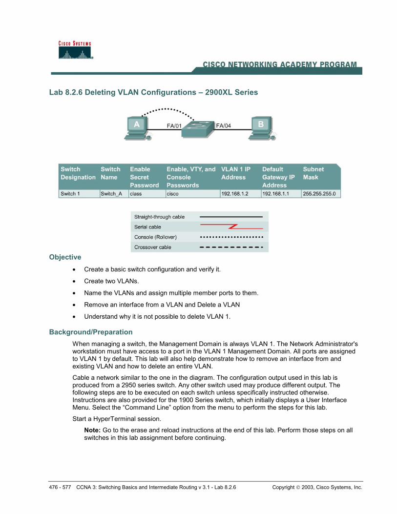
Lab 8.2.6 Deleting VLAN Configurations – 2900XL Series
Objective • Create a basic switch configuration and verify it.
• Create two VLANs.
• Name the VLANs and assign multiple member ports to them.
• Remove an interface from a VLAN and Delete a VLAN
• Understand why it is not possible to delete VLAN 1.
Background/Preparation When managing a switch, the Management Domain is always VLAN 1. The Network Administrator's workstation must have access to a port in the VLAN 1 Management Domain. All ports are assigned to VLAN 1 by default. This lab will also help demonstrate how to remove an interface from and existing VLAN and how to delete an entire VLAN.
Cable a network similar to the one in the diagram. The configuration output used in this lab is produced from a 2950 series switch. Any other switch used may produce different output. The following steps are to be executed on each switch unless specifically instructed otherwise. Instructions are also provided for the 1900 Series switch, which initially displays a User Interface Menu. Select the “Command Line” option from the menu to perform the steps for this lab.
Start a HyperTerminal session.
Note: Go to the erase and reload instructions at the end of this lab. Perform those steps on all switches in this lab assignment before continuing.
477 - 577 CCNA 3: Switching Basics and Intermediate Routing v 3.1 - Lab 8.2.6 Copyright 2003, Cisco Systems, Inc.
Step 1 Configure the switch Configure the hostname, access and command mode passwords, as well as the management LAN settings. These values are shown in the chart. If problems occur while performing this configuration, refer to the Basic Switch Configuration lab.
Step 2 Configure the hosts attached to the switch Configure the hosts to use the same subnet for the address, mask, and default gateway as on the switch.
Step 3 Verify connectivity a. To verify that the hosts and switch are correctly configured, ping the switch from the hosts.
b. Were the pings successful? Yes
c. If the answer is no, troubleshoot the host and switch configurations.
Step 4 Display the VLAN interface information a. On Switch_A, type the command show vlan at the Privileged EXEC prompt as follows:
Switch_A#show vlan
1900:
Switch_A#show vlan-membership
b. Which ports belong to the default VLAN? All
Step 5 Create and name two VLANs Enter the following commands to create and name two VLANs:
Switch_A#vlan database Switch_A(vlan)#vlan 2 name VLAN2 Switch_A(vlan)#vlan 3 name VLAN3 Switch_A(vlan)#exit
1900:
Switch_A#configure terminal Switch_A(config)#vlan 2 name VLAN2 Switch_A(config)#vlan 3 name VLAN3
Step 6 Assign ports to VLAN 2 Assigning ports to VLANs must be done from the interface mode. Enter the following commands to add ports 4, 5 and 6 to VLAN 2.
Switch_A#configure terminal Switch_A(config)#interface fastethernet 0/4 Switch_A(config-if)#switchport mode access Switch_A(config-if)#switchport access vlan 2 Switch_A(config-if)#interface fastethernet 0/5 Switch_A(config-if)#switchport mode access Switch_A(config-if)#switchport access vlan 2 Switch_A(config-if)#interface fastethernet 0/6
478 - 577 CCNA 3: Switching Basics and Intermediate Routing v 3.1 - Lab 8.2.6 Copyright 2003, Cisco Systems, Inc.
Switch_A(config-if)#switchport mode access Switch_A(config-if)#switchport access vlan 2 Switch_A(config-if)#end
1900:
Switch_A#configure terminal Switch_A(config)#interface Ethernet 0/4 Switch_A(config-if)#vlan static 2 Switch_A(config-if)#interface Ethernet 0/5 Switch_A(config-if)#vlan static 2 Switch_A(config-if)#interface Ethernet 0/6 Switch_A(config-if)#vlan static 2 Switch_A(config)#end
Step 7 Display the VLAN interface information a. On Switch_A, type the command show vlan at the Privileged EXEC prompt as follows:
Switch_A#show vlan
1900:
Switch_A#show vlan-membership
b. Are ports 4 through 6 assigned to VLAN 2? Yes
Step 8 Assign Ports to VLAN 3 Switch_A#configure terminal Switch_A(config-if)#interface fastethernet 0/7 Switch_A(config-if)#switchport mode access Switch_A(config-if)#switchport access vlan 3 Switch_A(config-if)#interface fastethernet 0/8 Switch_A(config-if)#switchport mode access Switch_A(config-if)#switchport access vlan 3 Switch_A(config-if)#interface fastethernet 0/9 Switch_A(config-if)#switchport mode access Switch_A(config-if)#switchport access vlan 3 Switch_A(config-if)#end
Step 9 Display the VLAN Interface Information a. On Switch_A, type the command show vlan at the Privileged EXEC prompt.
Switch_A#show vlan
b. Are ports 7-9 assigned to VLAN 3? Yes
Step 10 Test the VLANs Ping from the host in port 0/4 to the host in port 0/1.
a. Was the ping successful? No
Why? Ports have different vlan membership.
479 - 577 CCNA 3: Switching Basics and Intermediate Routing v 3.1 - Lab 8.2.6 Copyright 2003, Cisco Systems, Inc.
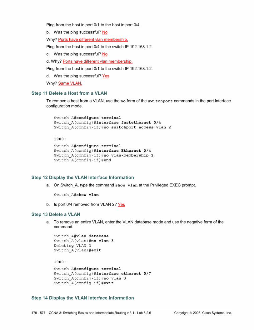
Ping from the host in port 0/1 to the host in port 0/4.
b. Was the ping successful? No
Why? Ports have different vlan membership.
Ping from the host in port 0/4 to the switch IP 192.168.1.2.
c. Was the ping successful? No
d. Why? Ports have different vlan membership.
Ping from the host in port 0/1 to the switch IP 192.168.1.2.
d. Was the ping successful? Yes
Why? Same VLAN.
Step 11 Delete a Host from a VLAN To remove a host from a VLAN, use the no form of the switchport commands in the port interface configuration mode.
Switch_A#configure terminal Switch_A(config)#interface fastethernet 0/4 Switch_A(config-if)#no switchport access vlan 2 1900:
Switch_A#configure terminal Switch_A(config)#interface Ethernet 0/4 Switch_A(config-if)#no vlan-membership 2 Switch_A(config-if)#end
Step 12 Display the VLAN Interface Information a. On Switch_A, type the command show vlan at the Privileged EXEC prompt.
Switch_A#show vlan
b. Is port 0/4 removed from VLAN 2? Yes
Step 13 Delete a VLAN a. To remove an entire VLAN, enter the VLAN database mode and use the negative form of the
command. Switch_A#vlan database Switch_A(vlan)#no vlan 3 Deleting VLAN 3 Switch_A(vlan)#exit
1900:
Switch_A#configure terminal Switch_A(config)#interface ethernet 0/7 Switch_A(config-if)#no vlan 3 Switch_A(config-if)#exit
Step 14 Display the VLAN Interface Information
480 - 577 CCNA 3: Switching Basics and Intermediate Routing v 3.1 - Lab 8.2.6 Copyright 2003, Cisco Systems, Inc.
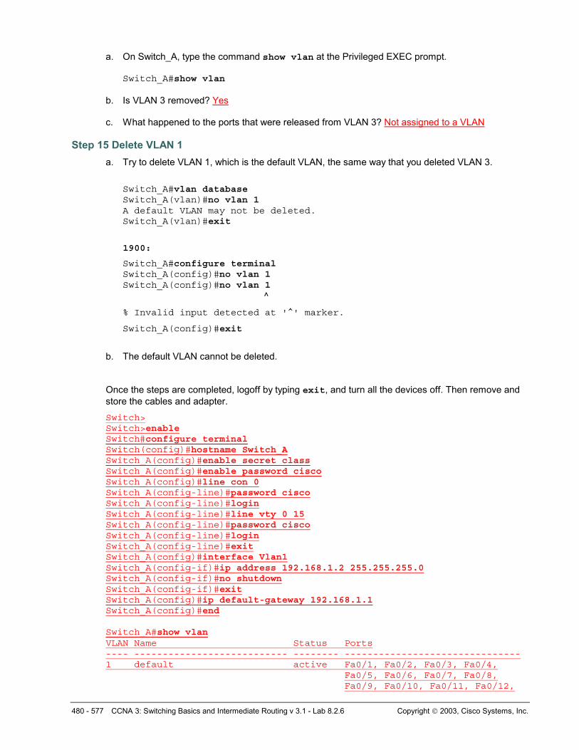
a. On Switch_A, type the command show vlan at the Privileged EXEC prompt. Switch_A#show vlan
b. Is VLAN 3 removed? Yes c. What happened to the ports that were released from VLAN 3? Not assigned to a VLAN
Step 15 Delete VLAN 1 a. Try to delete VLAN 1, which is the default VLAN, the same way that you deleted VLAN 3.
Switch_A#vlan database Switch_A(vlan)#no vlan 1 A default VLAN may not be deleted. Switch_A(vlan)#exit
1900:
Switch_A#configure terminal Switch_A(config)#no vlan 1 Switch_A(config)#no vlan 1 ^
% Invalid input detected at '^' marker.
Switch_A(config)#exit
b. The default VLAN cannot be deleted.
Once the steps are completed, logoff by typing exit, and turn all the devices off. Then remove and store the cables and adapter.
Switch> Switch>enable Switch#configure terminal Switch(config)#hostname Switch_A Switch_A(config)#enable secret class Switch_A(config)#enable password cisco Switch_A(config)#line con 0 Switch_A(config-line)#password cisco Switch_A(config-line)#login Switch_A(config-line)#line vty 0 15 Switch_A(config-line)#password cisco Switch_A(config-line)#login Switch_A(config-line)#exit Switch_A(config)#interface Vlan1 Switch_A(config-if)#ip address 192.168.1.2 255.255.255.0 Switch_A(config-if)#no shutdown Switch_A(config-if)#exit Switch_A(config)#ip default-gateway 192.168.1.1 Switch_A(config)#end Switch_A#show vlan VLAN Name Status Ports ---- --------------------------- -------- ------------------------------- 1 default active Fa0/1, Fa0/2, Fa0/3, Fa0/4,
Fa0/5, Fa0/6, Fa0/7, Fa0/8, Fa0/9, Fa0/10, Fa0/11, Fa0/12,
481 - 577 CCNA 3: Switching Basics and Intermediate Routing v 3.1 - Lab 8.2.6 Copyright 2003, Cisco Systems, Inc.
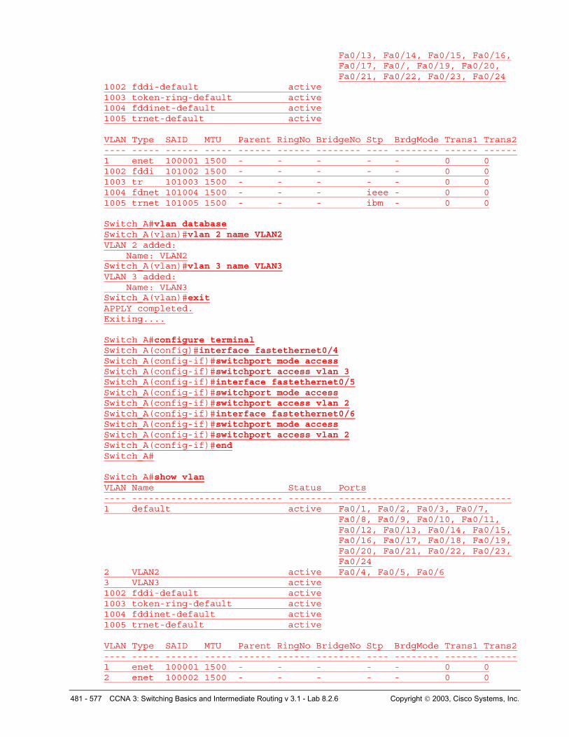
Fa0/13, Fa0/14, Fa0/15, Fa0/16, Fa0/17, Fa0/, Fa0/19, Fa0/20, Fa0/21, Fa0/22, Fa0/23, Fa0/24
1002 fddi-default active 1003 token-ring-default active 1004 fddinet-default active 1005 trnet-default active VLAN Type SAID MTU Parent RingNo BridgeNo Stp BrdgMode Trans1 Trans2 ---- ----- ------ ----- ------ ------ -------- ---- -------- ------ ------ 1 enet 100001 1500 - - - - - 0 0 1002 fddi 101002 1500 - - - - - 0 0 1003 tr 101003 1500 - - - - - 0 0 1004 fdnet 101004 1500 - - - ieee - 0 0 1005 trnet 101005 1500 - - - ibm - 0 0 Switch_A#vlan database Switch_A(vlan)#vlan 2 name VLAN2 VLAN 2 added: Name: VLAN2 Switch_A(vlan)#vlan 3 name VLAN3 VLAN 3 added: Name: VLAN3 Switch_A(vlan)#exit APPLY completed. Exiting.... Switch_A#configure terminal Switch_A(config)#interface fastethernet0/4 Switch_A(config-if)#switchport mode access Switch_A(config-if)#switchport access vlan 3 Switch_A(config-if)#interface fastethernet0/5 Switch_A(config-if)#switchport mode access Switch_A(config-if)#switchport access vlan 2 Switch_A(config-if)#interface fastethernet0/6 Switch_A(config-if)#switchport mode access Switch_A(config-if)#switchport access vlan 2 Switch_A(config-if)#end Switch_A# Switch_A#show vlan VLAN Name Status Ports ---- --------------------------- -------- ------------------------------- 1 default active Fa0/1, Fa0/2, Fa0/3, Fa0/7,
Fa0/8, Fa0/9, Fa0/10, Fa0/11, Fa0/12, Fa0/13, Fa0/14, Fa0/15, Fa0/16, Fa0/17, Fa0/18, Fa0/19, Fa0/20, Fa0/21, Fa0/22, Fa0/23, Fa0/24
2 VLAN2 active Fa0/4, Fa0/5, Fa0/6 3 VLAN3 active 1002 fddi-default active 1003 token-ring-default active 1004 fddinet-default active 1005 trnet-default active VLAN Type SAID MTU Parent RingNo BridgeNo Stp BrdgMode Trans1 Trans2 ---- ----- ------ ----- ------ ------ -------- ---- -------- ------ ------ 1 enet 100001 1500 - - - - - 0 0 2 enet 100002 1500 - - - - - 0 0
482 - 577 CCNA 3: Switching Basics and Intermediate Routing v 3.1 - Lab 8.2.6 Copyright 2003, Cisco Systems, Inc.
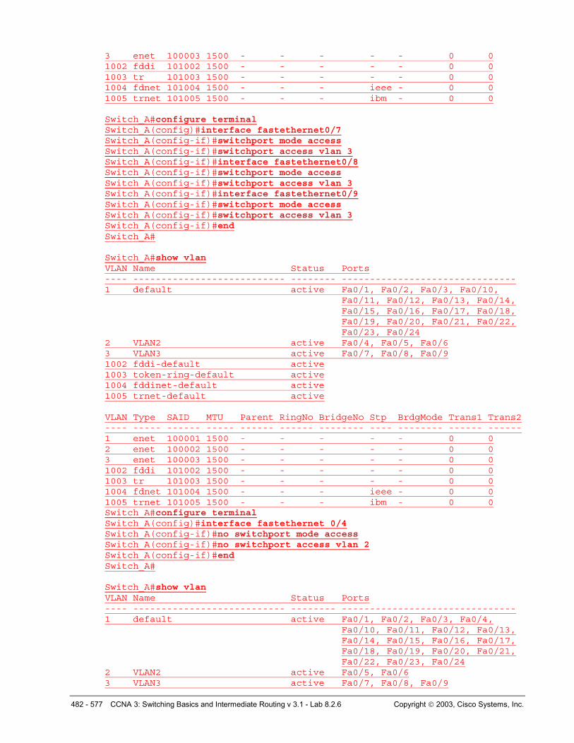
3 enet 100003 1500 - - - - - 0 0 1002 fddi 101002 1500 - - - - - 0 0 1003 tr 101003 1500 - - - - - 0 0 1004 fdnet 101004 1500 - - - ieee - 0 0 1005 trnet 101005 1500 - - - ibm - 0 0 Switch_A#configure terminal Switch_A(config)#interface fastethernet0/7 Switch_A(config-if)#switchport mode access Switch_A(config-if)#switchport access vlan 3 Switch_A(config-if)#interface fastethernet0/8 Switch_A(config-if)#switchport mode access Switch_A(config-if)#switchport access vlan 3 Switch_A(config-if)#interface fastethernet0/9 Switch_A(config-if)#switchport mode access Switch_A(config-if)#switchport access vlan 3 Switch_A(config-if)#end Switch_A# Switch_A#show vlan VLAN Name Status Ports ---- --------------------------- -------- ------------------------------- 1 default active Fa0/1, Fa0/2, Fa0/3, Fa0/10,
Fa0/11, Fa0/12, Fa0/13, Fa0/14, Fa0/15, Fa0/16, Fa0/17, Fa0/18, Fa0/19, Fa0/20, Fa0/21, Fa0/22, Fa0/23, Fa0/24
2 VLAN2 active Fa0/4, Fa0/5, Fa0/6 3 VLAN3 active Fa0/7, Fa0/8, Fa0/9 1002 fddi-default active 1003 token-ring-default active 1004 fddinet-default active 1005 trnet-default active VLAN Type SAID MTU Parent RingNo BridgeNo Stp BrdgMode Trans1 Trans2 ---- ----- ------ ----- ------ ------ -------- ---- -------- ------ ------ 1 enet 100001 1500 - - - - - 0 0 2 enet 100002 1500 - - - - - 0 0 3 enet 100003 1500 - - - - - 0 0 1002 fddi 101002 1500 - - - - - 0 0 1003 tr 101003 1500 - - - - - 0 0 1004 fdnet 101004 1500 - - - ieee - 0 0 1005 trnet 101005 1500 - - - ibm - 0 0 Switch_A#configure terminal Switch_A(config)#interface fastethernet 0/4 Switch_A(config-if)#no switchport mode access Switch_A(config-if)#no switchport access vlan 2 Switch_A(config-if)#end Switch_A# Switch_A#show vlan VLAN Name Status Ports ---- --------------------------- -------- ------------------------------- 1 default active Fa0/1, Fa0/2, Fa0/3, Fa0/4,
Fa0/10, Fa0/11, Fa0/12, Fa0/13, Fa0/14, Fa0/15, Fa0/16, Fa0/17, Fa0/18, Fa0/19, Fa0/20, Fa0/21, Fa0/22, Fa0/23, Fa0/24
2 VLAN2 active Fa0/5, Fa0/6 3 VLAN3 active Fa0/7, Fa0/8, Fa0/9
483 - 577 CCNA 3: Switching Basics and Intermediate Routing v 3.1 - Lab 8.2.6 Copyright 2003, Cisco Systems, Inc.
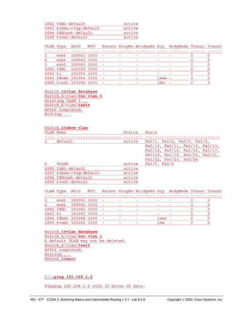
1002 fddi-default active 1003 token-ring-default active 1004 fddinet-default active 1005 trnet-default active VLAN Type SAID MTU Parent RingNo BridgeNo Stp BrdgMode Trans1 Trans2 ---- ----- ------ ----- ------ ------ -------- ---- -------- ------ ------ 1 enet 100001 1500 - - - - - 0 0 2 enet 100002 1500 - - - - - 0 0 3 enet 100003 1500 - - - - - 0 0 1002 fddi 101002 1500 - - - - - 0 0 1003 tr 101003 1500 - - - - - 0 0 1004 fdnet 101004 1500 - - - ieee - 0 0 1005 trnet 101005 1500 - - - ibm - 0 0 Switch_A#vlan database Switch_A(vlan)#no vlan 3 Deleting VLAN 3... Switch_A(vlan)#exit APPLY completed. Exiting.... Switch_A#show vlan VLAN Name Status Ports ---- --------------------------- -------- ------------------------------- 1 default active Fa0/1, Fa0/2, Fa0/3, Fa0/4,
Fa0/10, Fa0/11, Fa0/12, Fa0/13, Fa0/14, Fa0/15, Fa0/16, Fa0/17, Fa0/18, Fa0/19, Fa0/20, Fa0/21, Fa0/22, Fa0/23, Fa0/24
2 VLAN2 active Fa0/5, Fa0/6 1002 fddi-default active 1003 token-ring-default active 1004 fddinet-default active 1005 trnet-default active VLAN Type SAID MTU Parent RingNo BridgeNo Stp BrdgMode Trans1 Trans2 ---- ----- ------ ----- ------ ------ -------- ---- -------- ------ ------ 1 enet 100001 1500 - - - - - 0 0 2 enet 100002 1500 - - - - - 0 0 1002 fddi 101002 1500 - - - - - 0 0 1003 tr 101003 1500 - - - - - 0 0 1004 fdnet 101004 1500 - - - ieee - 0 0 1005 trnet 101005 1500 - - - ibm - 0 0 Switch_A#vlan database Switch_A(vlan)#no vlan 1 A default VLAN may not be deleted. Switch_A(vlan)#exit APPLY completed. Exiting.... Switch_A#exit
C:\>ping 192.168.1.2 Pinging 192.168.1.2 with 32 bytes of data:
484 - 577 CCNA 3: Switching Basics and Intermediate Routing v 3.1 - Lab 8.2.6 Copyright 2003, Cisco Systems, Inc.
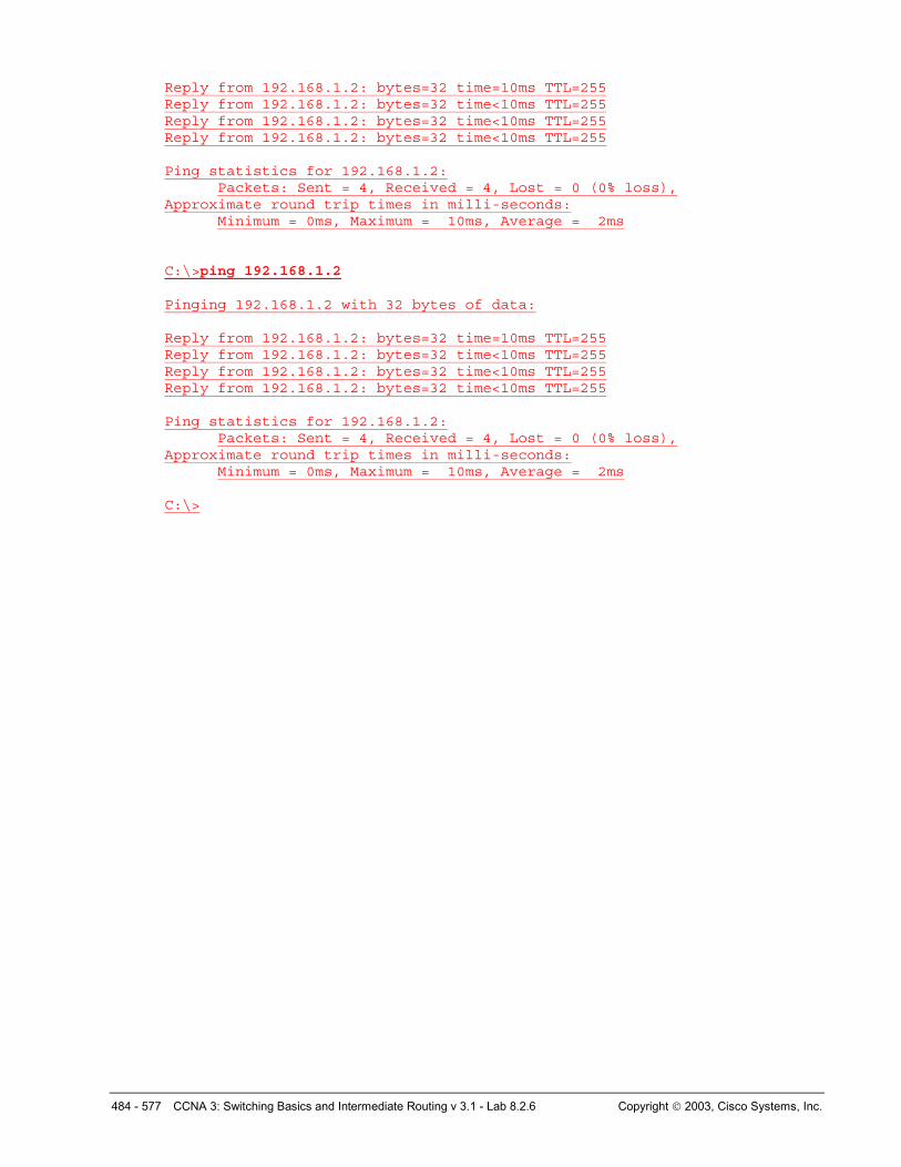
Reply from 192.168.1.2: bytes=32 time=10ms TTL=255 Reply from 192.168.1.2: bytes=32 time<10ms TTL=255 Reply from 192.168.1.2: bytes=32 time<10ms TTL=255 Reply from 192.168.1.2: bytes=32 time<10ms TTL=255 Ping statistics for 192.168.1.2:
Packets: Sent = 4, Received = 4, Lost = 0 (0% loss), Approximate round trip times in milli-seconds:
Minimum = 0ms, Maximum = 10ms, Average = 2ms C:\>ping 192.168.1.2 Pinging 192.168.1.2 with 32 bytes of data: Reply from 192.168.1.2: bytes=32 time=10ms TTL=255 Reply from 192.168.1.2: bytes=32 time<10ms TTL=255 Reply from 192.168.1.2: bytes=32 time<10ms TTL=255 Reply from 192.168.1.2: bytes=32 time<10ms TTL=255 Ping statistics for 192.168.1.2:
Packets: Sent = 4, Received = 4, Lost = 0 (0% loss), Approximate round trip times in milli-seconds:
Minimum = 0ms, Maximum = 10ms, Average = 2ms C:\>
485 - 577 CCNA 3: Switching Basics and Intermediate Routing v 3.1 - Lab 8.2.6 Copyright 2003, Cisco Systems, Inc.
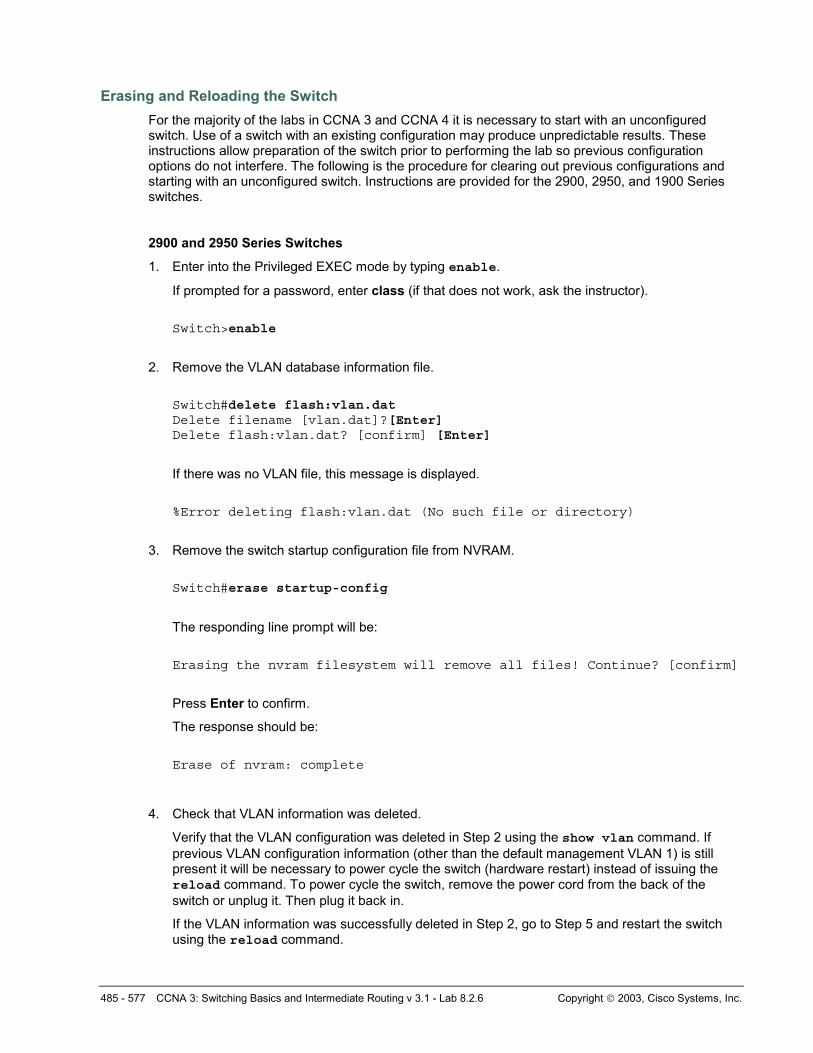
Erasing and Reloading the Switch For the majority of the labs in CCNA 3 and CCNA 4 it is necessary to start with an unconfigured switch. Use of a switch with an existing configuration may produce unpredictable results. These instructions allow preparation of the switch prior to performing the lab so previous configuration options do not interfere. The following is the procedure for clearing out previous configurations and starting with an unconfigured switch. Instructions are provided for the 2900, 2950, and 1900 Series switches.
2900 and 2950 Series Switches
1. Enter into the Privileged EXEC mode by typing enable.
If prompted for a password, enter class (if that does not work, ask the instructor).
Switch>enable
2. Remove the VLAN database information file.
Switch#delete flash:vlan.dat Delete filename [vlan.dat]?[Enter] Delete flash:vlan.dat? [confirm] [Enter]
If there was no VLAN file, this message is displayed.
%Error deleting flash:vlan.dat (No such file or directory)
3. Remove the switch startup configuration file from NVRAM.
Switch#erase startup-config
The responding line prompt will be:
Erasing the nvram filesystem will remove all files! Continue? [confirm]
Press Enter to confirm.
The response should be:
Erase of nvram: complete
4. Check that VLAN information was deleted.
Verify that the VLAN configuration was deleted in Step 2 using the show vlan command. If previous VLAN configuration information (other than the default management VLAN 1) is still present it will be necessary to power cycle the switch (hardware restart) instead of issuing the reload command. To power cycle the switch, remove the power cord from the back of the switch or unplug it. Then plug it back in.
If the VLAN information was successfully deleted in Step 2, go to Step 5 and restart the switch using the reload command.
486 - 577 CCNA 3: Switching Basics and Intermediate Routing v 3.1 - Lab 8.2.6 Copyright 2003, Cisco Systems, Inc.
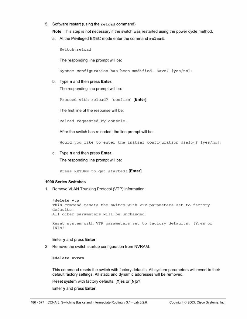
5. Software restart (using the reload command)
Note: This step is not necessary if the switch was restarted using the power cycle method.
a. At the Privileged EXEC mode enter the command reload.
Switch#reload
The responding line prompt will be:
System configuration has been modified. Save? [yes/no]:
b. Type n and then press Enter.
The responding line prompt will be:
Proceed with reload? [confirm] [Enter]
The first line of the response will be:
Reload requested by console.
After the switch has reloaded, the line prompt will be:
Would you like to enter the initial configuration dialog? [yes/no]:
c. Type n and then press Enter.
The responding line prompt will be:
Press RETURN to get started! [Enter]
1900 Series Switches
1. Remove VLAN Trunking Protocol (VTP) information.
#delete vtp This command resets the switch with VTP parameters set to factory defaults. All other parameters will be unchanged. Reset system with VTP parameters set to factory defaults, [Y]es or [N]o?
Enter y and press Enter.
2. Remove the switch startup configuration from NVRAM.
#delete nvram
This command resets the switch with factory defaults. All system parameters will revert to their default factory settings. All static and dynamic addresses will be removed.
Reset system with factory defaults, [Y]es or [N]o?
Enter y and press Enter.
487 - 577 CCNA 3: Switching Basics and Intermediate Routing v 3.1 - Lab 8.2.6 Copyright 2003, Cisco Systems, Inc.
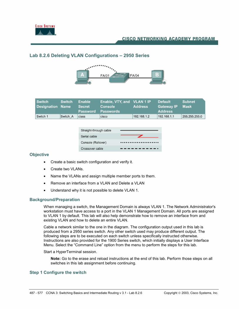
Lab 8.2.6 Deleting VLAN Configurations – 2950 Series
Objective • Create a basic switch configuration and verify it.
• Create two VLANs.
• Name the VLANs and assign multiple member ports to them.
• Remove an interface from a VLAN and Delete a VLAN
• Understand why it is not possible to delete VLAN 1.
Background/Preparation When managing a switch, the Management Domain is always VLAN 1. The Network Administrator's workstation must have access to a port in the VLAN 1 Management Domain. All ports are assigned to VLAN 1 by default. This lab will also help demonstrate how to remove an interface from and existing VLAN and how to delete an entire VLAN.
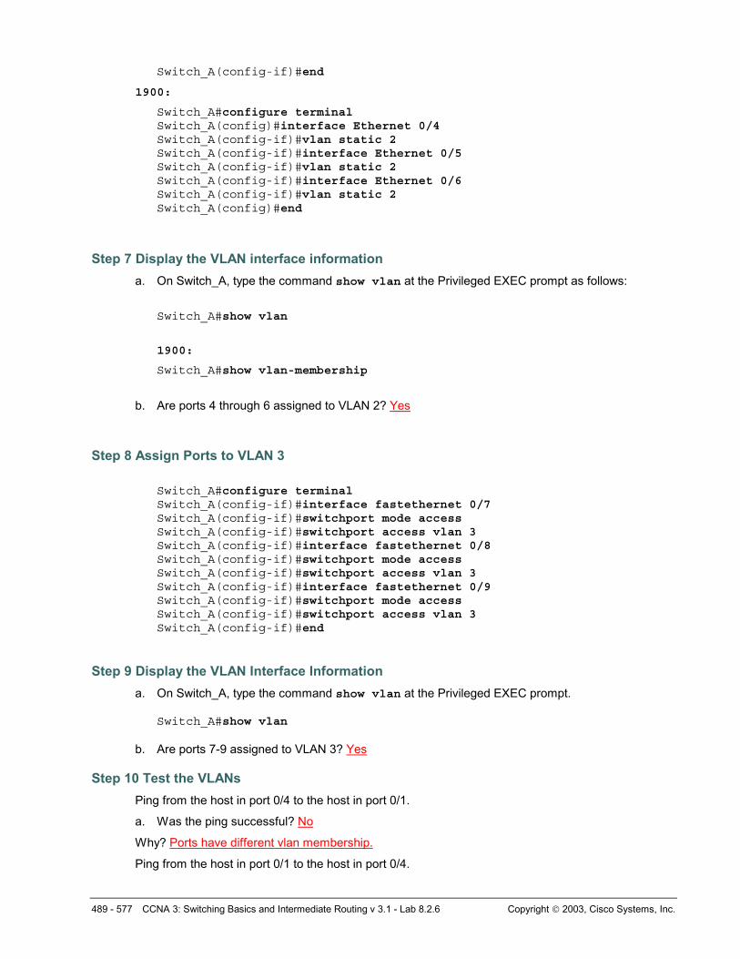
Cable a network similar to the one in the diagram. The configuration output used in this lab is produced from a 2950 series switch. Any other switch used may produce different output. The following steps are to be executed on each switch unless specifically instructed otherwise. Instructions are also provided for the 1900 Series switch, which initially displays a User Interface Menu. Select the “Command Line” option from the menu to perform the steps for this lab.
Start a HyperTerminal session.
Note: Go to the erase and reload instructions at the end of this lab. Perform those steps on all switches in this lab assignment before continuing.
Step 1 Configure the switch
488 - 577 CCNA 3: Switching Basics and Intermediate Routing v 3.1 - Lab 8.2.6 Copyright 2003, Cisco Systems, Inc.
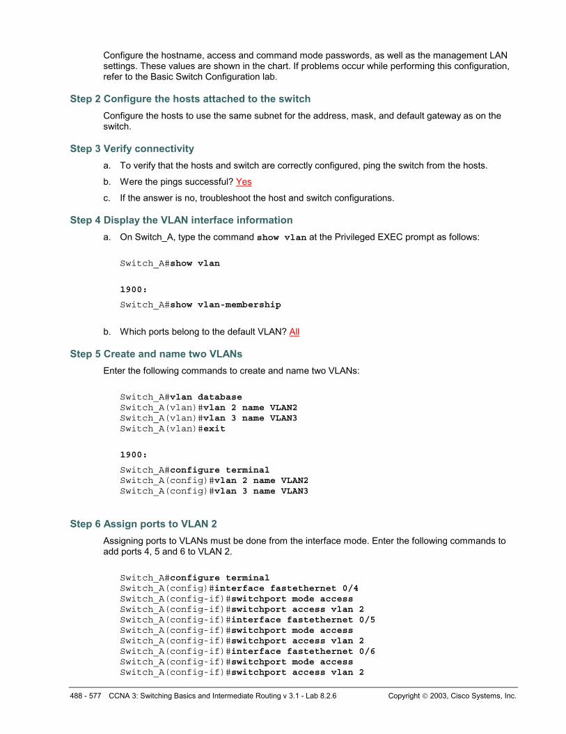
Configure the hostname, access and command mode passwords, as well as the management LAN settings. These values are shown in the chart. If problems occur while performing this configuration, refer to the Basic Switch Configuration lab.
Step 2 Configure the hosts attached to the switch Configure the hosts to use the same subnet for the address, mask, and default gateway as on the switch.
Step 3 Verify connectivity a. To verify that the hosts and switch are correctly configured, ping the switch from the hosts.
b. Were the pings successful? Yes
c. If the answer is no, troubleshoot the host and switch configurations.
Step 4 Display the VLAN interface information a. On Switch_A, type the command show vlan at the Privileged EXEC prompt as follows:
Switch_A#show vlan
1900:
Switch_A#show vlan-membership
b. Which ports belong to the default VLAN? All
Step 5 Create and name two VLANs Enter the following commands to create and name two VLANs:
Switch_A#vlan database Switch_A(vlan)#vlan 2 name VLAN2 Switch_A(vlan)#vlan 3 name VLAN3 Switch_A(vlan)#exit
1900:
Switch_A#configure terminal Switch_A(config)#vlan 2 name VLAN2 Switch_A(config)#vlan 3 name VLAN3
Step 6 Assign ports to VLAN 2 Assigning ports to VLANs must be done from the interface mode. Enter the following commands to add ports 4, 5 and 6 to VLAN 2.
Switch_A#configure terminal Switch_A(config)#interface fastethernet 0/4 Switch_A(config-if)#switchport mode access Switch_A(config-if)#switchport access vlan 2 Switch_A(config-if)#interface fastethernet 0/5 Switch_A(config-if)#switchport mode access Switch_A(config-if)#switchport access vlan 2 Switch_A(config-if)#interface fastethernet 0/6 Switch_A(config-if)#switchport mode access Switch_A(config-if)#switchport access vlan 2
489 - 577 CCNA 3: Switching Basics and Intermediate Routing v 3.1 - Lab 8.2.6 Copyright 2003, Cisco Systems, Inc.
Switch_A(config-if)#end
1900:
Switch_A#configure terminal Switch_A(config)#interface Ethernet 0/4 Switch_A(config-if)#vlan static 2 Switch_A(config-if)#interface Ethernet 0/5 Switch_A(config-if)#vlan static 2 Switch_A(config-if)#interface Ethernet 0/6 Switch_A(config-if)#vlan static 2 Switch_A(config)#end
Step 7 Display the VLAN interface information a. On Switch_A, type the command show vlan at the Privileged EXEC prompt as follows:
Switch_A#show vlan
1900:
Switch_A#show vlan-membership
b. Are ports 4 through 6 assigned to VLAN 2? Yes
Step 8 Assign Ports to VLAN 3 Switch_A#configure terminal Switch_A(config-if)#interface fastethernet 0/7 Switch_A(config-if)#switchport mode access Switch_A(config-if)#switchport access vlan 3 Switch_A(config-if)#interface fastethernet 0/8 Switch_A(config-if)#switchport mode access Switch_A(config-if)#switchport access vlan 3 Switch_A(config-if)#interface fastethernet 0/9 Switch_A(config-if)#switchport mode access Switch_A(config-if)#switchport access vlan 3 Switch_A(config-if)#end
Step 9 Display the VLAN Interface Information a. On Switch_A, type the command show vlan at the Privileged EXEC prompt.
Switch_A#show vlan
b. Are ports 7-9 assigned to VLAN 3? Yes
Step 10 Test the VLANs Ping from the host in port 0/4 to the host in port 0/1.
a. Was the ping successful? No
Why? Ports have different vlan membership.
Ping from the host in port 0/1 to the host in port 0/4.
490 - 577 CCNA 3: Switching Basics and Intermediate Routing v 3.1 - Lab 8.2.6 Copyright 2003, Cisco Systems, Inc.
b. Was the ping successful? No
Why? Ports have different vlan membership.
Ping from the host in port 0/4 to the switch IP 192.168.1.2.
c. Was the ping successful? No
d. Why? Ports have different vlan membership.
Ping from the host in port 0/1 to the switch IP 192.168.1.2.
d. Was the ping successful? Yes
Why? Same VLAN
Step 11 Delete a Host from a VLAN To remove a host from a VLAN, use the no form of the switchport commands in the port interface configuration mode.
Switch_A#configure terminal Switch_A(config)#interface fastethernet 0/4 Switch_A(config-if)#no switchport access vlan 2 1900:
Switch_A#configure terminal Switch_A(config)#interface Ethernet 0/4 Switch_A(config-if)#no vlan-membership 2 Switch_A(config-if)#end
Step 12 Display the VLAN Interface Information a. On Switch_A, type the command show vlan at the Privileged EXEC prompt.
Switch_A#show vlan
b. Is port 0/4 removed from VLAN 2? Yes
Step 13 Delete a VLAN a. To remove an entire VLAN, enter the VLAN database mode and use the negative form of the
command. Switch_A#vlan database Switch_A(vlan)#no vlan 3 Deleting VLAN 3 Switch_A(vlan)#exit
1900:
Switch_A#config terminal Switch_A(config)#interface ethernet 0/7 Switch_A(config-if)#no vlan 3 Switch_A(config-if)#exit
Step 14 Display the VLAN Interface Information a. On Switch_A, type the command show vlan at the Privileged EXEC prompt.
491 - 577 CCNA 3: Switching Basics and Intermediate Routing v 3.1 - Lab 8.2.6 Copyright 2003, Cisco Systems, Inc.
Switch_A#show vlan
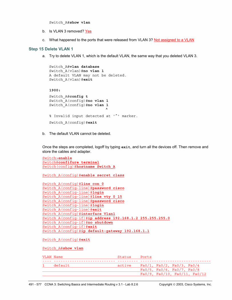
b. Is VLAN 3 removed? Yes c. What happened to the ports that were released from VLAN 3? Not assigned to a VLAN
Step 15 Delete VLAN 1 a. Try to delete VLAN 1, which is the default VLAN, the same way that you deleted VLAN 3.
Switch_A#vlan database Switch_A(vlan)#no vlan 1 A default VLAN may not be deleted. Switch_A(vlan)#exit
1900:
Switch_A#config t Switch_A(config)#no vlan 1 Switch_A(config)#no vlan 1 ^
% Invalid input detected at '^' marker.
Switch_A(config)#exit
b. The default VLAN cannot be deleted.
Once the steps are completed, logoff by typing exit, and turn all the devices off. Then remove and store the cables and adapter. Switch>enable Switch#confifure terminal Switch(config)#hostname Switch_A Switch_A(config)#enable secret class Switch_A(config)#line con 0 Switch_A(config-line)#password cisco Switch_A(config-line)#login Switch_A(config-line)#line vty 0 15 Switch_A(config-line)#password cisco Switch_A(config-line)#login Switch_A(config-line)#exit Switch_A(config)#interface Vlan1 Switch_A(config-if)#ip address 192.168.1.2 255.255.255.0 Switch_A(config-if)#no shutdown Switch_A(config-if)#exit Switch_A(config)#ip default-gateway 192.168.1.1 Switch_A(config)#exit Switch_A#show vlan VLAN Name Status Ports ---- --------------------------- --------- ------------------------------- 1 default active Fa0/1, Fa0/2, Fa0/3, Fa0/4 Fa0/5, Fa0/6, Fa0/7, Fa0/8 Fa0/9, Fa0/10, Fa0/11, Fa0/12
492 - 577 CCNA 3: Switching Basics and Intermediate Routing v 3.1 - Lab 8.2.6 Copyright 2003, Cisco Systems, Inc.
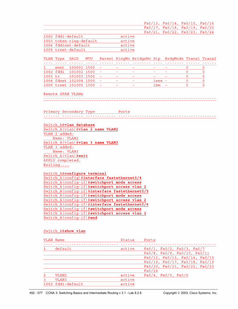
Fa0/13, Fa0/14, Fa0/15, Fa0/16 Fa0/17, Fa0/18, Fa0/19, Fa0/20 Fa0/21, Fa0/22, Fa0/23, Fa0/24 1002 fddi-default active 1003 token-ring-default active 1004 fddinet-default active 1005 trnet-default active VLAN Type SAID MTU Parent RingNo BridgeNo Stp BrdgMode Trans1 Trans2 ---- ----- ------ ----- ------ ------ -------- ---- -------- ------ ------ 1 enet 100001 1500 - - - - - 0 0 1002 fddi 101002 1500 - - - - - 0 0 1003 tr 101003 1500 - - - - - 0 0 1004 fdnet 101004 1500 - - - ieee - 0 0 1005 trnet 101005 1500 - - - ibm - 0 0 Remote SPAN VLANs -------------------------------------------------------------------------- Primary Secondary Type Ports ------- --------- ------------- ------------------------------------------ Switch_A#vlan database Switch_A(vlan)#vlan 2 name VLAN2 VLAN 2 added: Name: VLAN2 Switch_A(vlan)#vlan 3 name VLAN3 VLAN 3 added: Name: VLAN3 Switch_A(vlan)#exit APPLY completed. Exiting.... Switch_A#configure terminal Switch_A(config)#interface fastethernet0/4 Switch_A(config-if)#switchport mode access Switch_A(config-if)#switchport access vlan 2 Switch_A(config-if)#interface fastethernet0/5 Switch_A(config-if)#switchport mode access Switch_A(config-if)#switchport access vlan 2 Switch_A(config-if)#interface fastethernet0/6 Switch_A(config-if)#switchport mode access Switch_A(config-if)#switchport access vlan 2 Switch_A(config-if)#end Switch_A#show vlan VLAN Name Status Ports ---- --------------------------- --------- ------------------------------- 1 default active Fa0/1, Fa0/2, Fa0/3, Fa0/7 Fa0/8, Fa0/9, Fa0/10, Fa0/11 Fa0/12, Fa0/13, Fa0/14, Fa0/15 Fa0/16, Fa0/17, Fa0/18, Fa0/19 Fa0/20, Fa0/21, Fa0/22, Fa0/23 Fa0/24 2 VLAN2 active Fa0/4, Fa0/5, Fa0/6 3 VLAN3 active 1002 fddi-default active
493 - 577 CCNA 3: Switching Basics and Intermediate Routing v 3.1 - Lab 8.2.6 Copyright 2003, Cisco Systems, Inc.
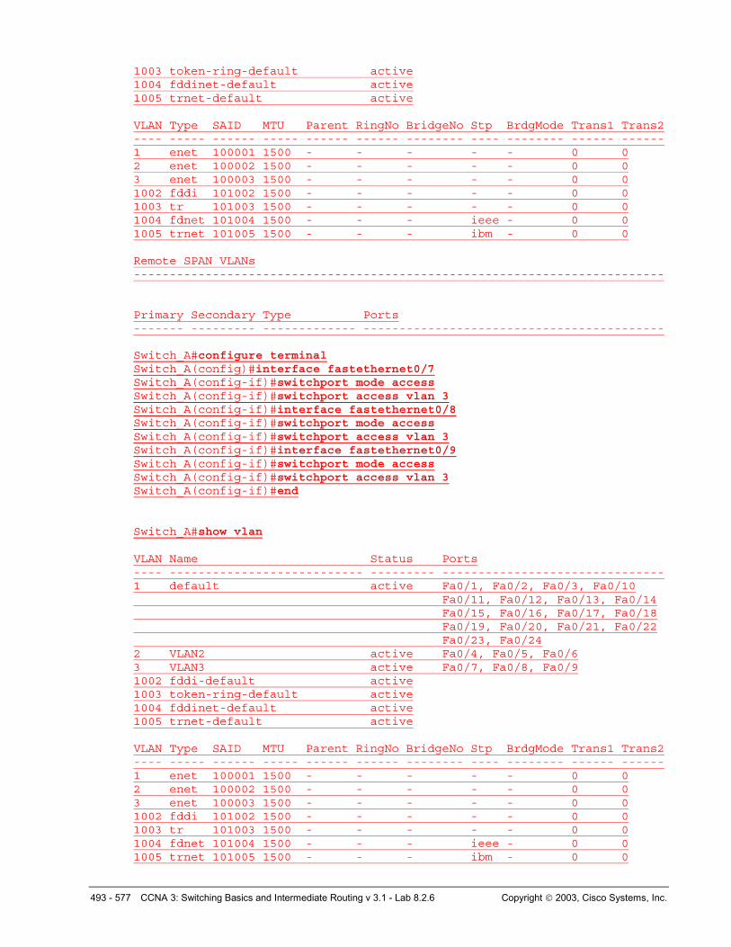
1003 token-ring-default active 1004 fddinet-default active 1005 trnet-default active VLAN Type SAID MTU Parent RingNo BridgeNo Stp BrdgMode Trans1 Trans2 ---- ----- ------ ----- ------ ------ -------- ---- -------- ------ ------ 1 enet 100001 1500 - - - - - 0 0 2 enet 100002 1500 - - - - - 0 0 3 enet 100003 1500 - - - - - 0 0 1002 fddi 101002 1500 - - - - - 0 0 1003 tr 101003 1500 - - - - - 0 0 1004 fdnet 101004 1500 - - - ieee - 0 0 1005 trnet 101005 1500 - - - ibm - 0 0 Remote SPAN VLANs -------------------------------------------------------------------------- Primary Secondary Type Ports ------- --------- ------------- ------------------------------------------ Switch_A#configure terminal Switch_A(config)#interface fastethernet0/7 Switch_A(config-if)#switchport mode access Switch_A(config-if)#switchport access vlan 3 Switch_A(config-if)#interface fastethernet0/8 Switch_A(config-if)#switchport mode access Switch_A(config-if)#switchport access vlan 3 Switch_A(config-if)#interface fastethernet0/9 Switch_A(config-if)#switchport mode access Switch_A(config-if)#switchport access vlan 3 Switch_A(config-if)#end Switch_A#show vlan VLAN Name Status Ports ---- --------------------------- --------- ------------------------------- 1 default active Fa0/1, Fa0/2, Fa0/3, Fa0/10 Fa0/11, Fa0/12, Fa0/13, Fa0/14 Fa0/15, Fa0/16, Fa0/17, Fa0/18 Fa0/19, Fa0/20, Fa0/21, Fa0/22 Fa0/23, Fa0/24 2 VLAN2 active Fa0/4, Fa0/5, Fa0/6 3 VLAN3 active Fa0/7, Fa0/8, Fa0/9 1002 fddi-default active 1003 token-ring-default active 1004 fddinet-default active 1005 trnet-default active VLAN Type SAID MTU Parent RingNo BridgeNo Stp BrdgMode Trans1 Trans2 ---- ----- ------ ----- ------ ------ -------- ---- -------- ------ ------ 1 enet 100001 1500 - - - - - 0 0 2 enet 100002 1500 - - - - - 0 0 3 enet 100003 1500 - - - - - 0 0 1002 fddi 101002 1500 - - - - - 0 0 1003 tr 101003 1500 - - - - - 0 0 1004 fdnet 101004 1500 - - - ieee - 0 0 1005 trnet 101005 1500 - - - ibm - 0 0
494 - 577 CCNA 3: Switching Basics and Intermediate Routing v 3.1 - Lab 8.2.6 Copyright 2003, Cisco Systems, Inc.
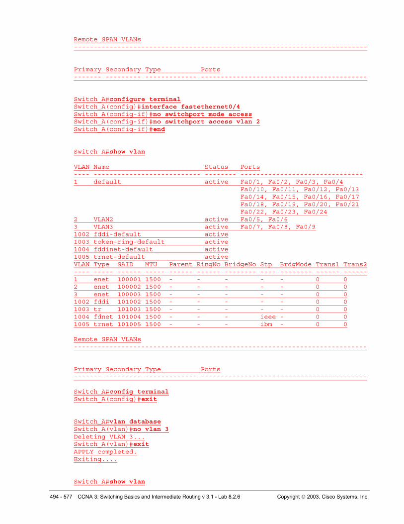
Remote SPAN VLANs -------------------------------------------------------------------------- Primary Secondary Type Ports ------- --------- ------------- ------------------------------------------ Switch_A#configure terminal Switch_A(config)#interface fastethernet0/4 Switch_A(config-if)#no switchport mode access Switch_A(config-if)#no switchport access vlan 2 Switch_A(config-if)#end Switch_A#show vlan VLAN Name Status Ports ---- --------------------------- -------- ------------------------------- 1 default active Fa0/1, Fa0/2, Fa0/3, Fa0/4
Fa0/10, Fa0/11, Fa0/12, Fa0/13 Fa0/14, Fa0/15, Fa0/16, Fa0/17 Fa0/18, Fa0/19, Fa0/20, Fa0/21 Fa0/22, Fa0/23, Fa0/24
2 VLAN2 active Fa0/5, Fa0/6 3 VLAN3 active Fa0/7, Fa0/8, Fa0/9 1002 fddi-default active 1003 token-ring-default active 1004 fddinet-default active 1005 trnet-default active VLAN Type SAID MTU Parent RingNo BridgeNo Stp BrdgMode Trans1 Trans2 ---- ----- ------ ----- ------ ------ -------- ---- -------- ------ ------ 1 enet 100001 1500 - - - - - 0 0 2 enet 100002 1500 - - - - - 0 0 3 enet 100003 1500 - - - - - 0 0 1002 fddi 101002 1500 - - - - - 0 0 1003 tr 101003 1500 - - - - - 0 0 1004 fdnet 101004 1500 - - - ieee - 0 0 1005 trnet 101005 1500 - - - ibm - 0 0 Remote SPAN VLANs -------------------------------------------------------------------------- Primary Secondary Type Ports ------- --------- ------------- ------------------------------------------ Switch_A#config terminal Switch_A(config)#exit Switch_A#vlan database Switch_A(vlan)#no vlan 3 Deleting VLAN 3... Switch_A(vlan)#exit APPLY completed. Exiting.... Switch_A#show vlan
495 - 577 CCNA 3: Switching Basics and Intermediate Routing v 3.1 - Lab 8.2.6 Copyright 2003, Cisco Systems, Inc.
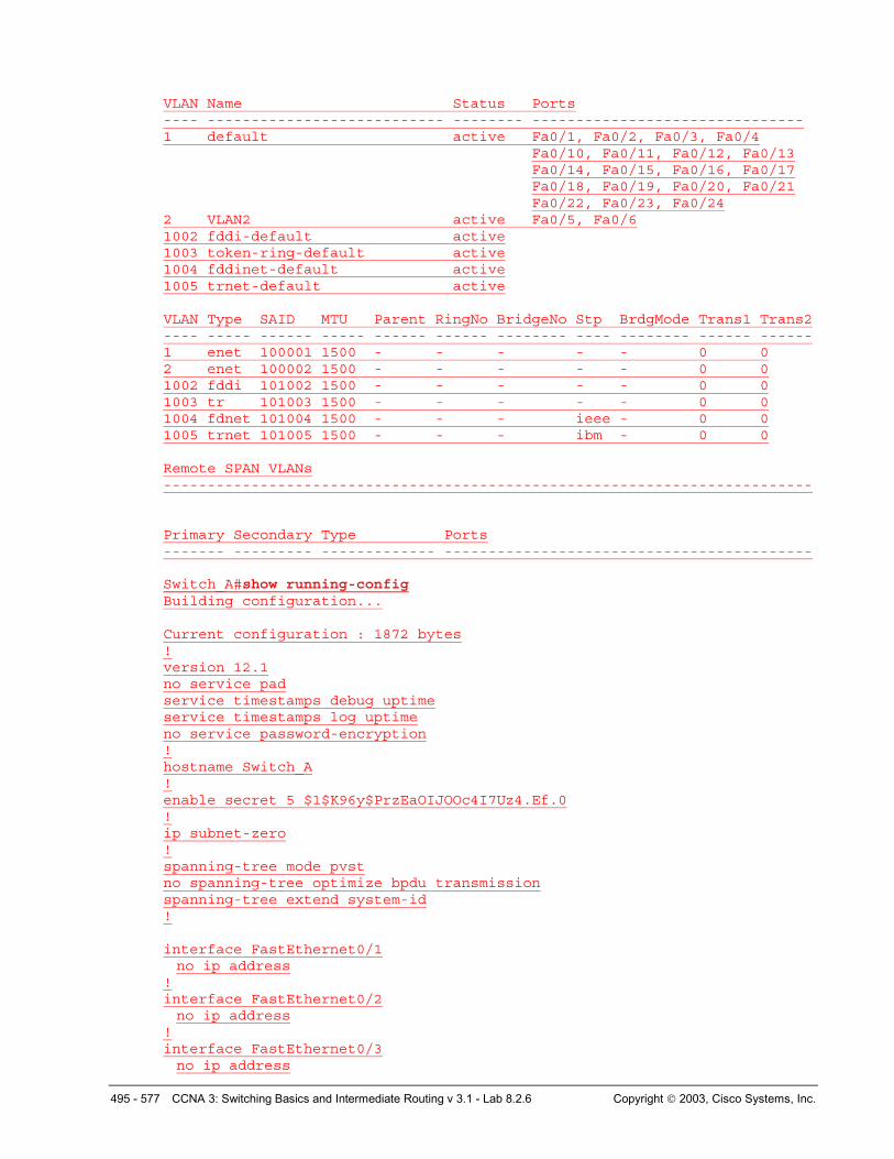
VLAN Name Status Ports ---- --------------------------- -------- ------------------------------- 1 default active Fa0/1, Fa0/2, Fa0/3, Fa0/4
Fa0/10, Fa0/11, Fa0/12, Fa0/13 Fa0/14, Fa0/15, Fa0/16, Fa0/17 Fa0/18, Fa0/19, Fa0/20, Fa0/21 Fa0/22, Fa0/23, Fa0/24
2 VLAN2 active Fa0/5, Fa0/6 1002 fddi-default active 1003 token-ring-default active 1004 fddinet-default active 1005 trnet-default active VLAN Type SAID MTU Parent RingNo BridgeNo Stp BrdgMode Trans1 Trans2 ---- ----- ------ ----- ------ ------ -------- ---- -------- ------ ------ 1 enet 100001 1500 - - - - - 0 0 2 enet 100002 1500 - - - - - 0 0 1002 fddi 101002 1500 - - - - - 0 0 1003 tr 101003 1500 - - - - - 0 0 1004 fdnet 101004 1500 - - - ieee - 0 0 1005 trnet 101005 1500 - - - ibm - 0 0 Remote SPAN VLANs -------------------------------------------------------------------------- Primary Secondary Type Ports ------- --------- ------------- ------------------------------------------ Switch_A#show running-config Building configuration... Current configuration : 1872 bytes ! version 12.1 no service pad service timestamps debug uptime service timestamps log uptime no service password-encryption ! hostname Switch_A ! enable secret 5 $1$K96y$PrzEaOIJOOc4I7Uz4.Ef.0 ! ip subnet-zero ! spanning-tree mode pvst no spanning-tree optimize bpdu transmission spanning-tree extend system-id ! interface FastEthernet0/1 no ip address
! interface FastEthernet0/2 no ip address
! interface FastEthernet0/3 no ip address
496 - 577 CCNA 3: Switching Basics and Intermediate Routing v 3.1 - Lab 8.2.6 Copyright 2003, Cisco Systems, Inc.
! interface FastEthernet0/4 no ip address
! interface FastEthernet0/5 switchport access vlan 2 switchport mode access no ip address
! interface FastEthernet0/6 switchport access vlan 2 switchport mode access no ip address
! interface FastEthernet0/7 switchport access vlan 3
switchport mode access no ip address
! interface FastEthernet0/8 switchport access vlan 3
switchport mode access no ip address
! interface FastEthernet0/9 switchport access vlan 3 switchport mode access no ip address
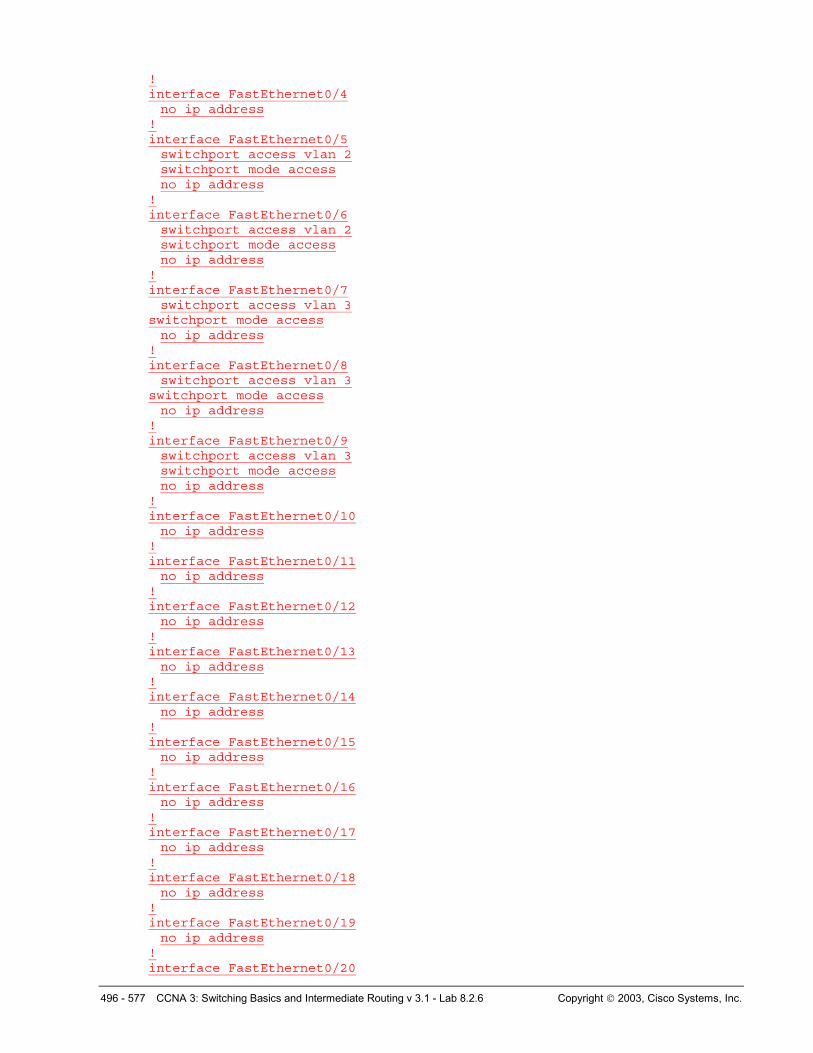
! interface FastEthernet0/10 no ip address
! interface FastEthernet0/11 no ip address
! interface FastEthernet0/12 no ip address
! interface FastEthernet0/13 no ip address
! interface FastEthernet0/14 no ip address
! interface FastEthernet0/15 no ip address
! interface FastEthernet0/16 no ip address
! interface FastEthernet0/17 no ip address
! interface FastEthernet0/18 no ip address
! interface FastEthernet0/19 no ip address
! interface FastEthernet0/20
497 - 577 CCNA 3: Switching Basics and Intermediate Routing v 3.1 - Lab 8.2.6 Copyright 2003, Cisco Systems, Inc.
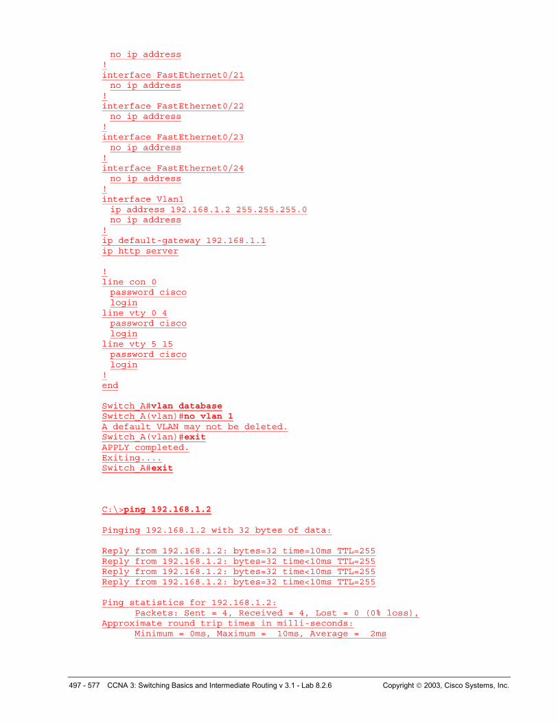
no ip address ! interface FastEthernet0/21 no ip address
! interface FastEthernet0/22 no ip address
! interface FastEthernet0/23 no ip address
! interface FastEthernet0/24 no ip address
! interface Vlan1 ip address 192.168.1.2 255.255.255.0 no ip address
! ip default-gateway 192.168.1.1 ip http server ! line con 0 password cisco login
line vty 0 4 password cisco login
line vty 5 15 password cisco login
! end Switch_A#vlan database Switch_A(vlan)#no vlan 1 A default VLAN may not be deleted. Switch_A(vlan)#exit APPLY completed. Exiting.... Switch_A#exit C:\>ping 192.168.1.2 Pinging 192.168.1.2 with 32 bytes of data: Reply from 192.168.1.2: bytes=32 time=10ms TTL=255 Reply from 192.168.1.2: bytes=32 time<10ms TTL=255 Reply from 192.168.1.2: bytes=32 time<10ms TTL=255 Reply from 192.168.1.2: bytes=32 time<10ms TTL=255 Ping statistics for 192.168.1.2:
Packets: Sent = 4, Received = 4, Lost = 0 (0% loss), Approximate round trip times in milli-seconds:
Minimum = 0ms, Maximum = 10ms, Average = 2ms
498 - 577 CCNA 3: Switching Basics and Intermediate Routing v 3.1 - Lab 8.2.6 Copyright 2003, Cisco Systems, Inc.
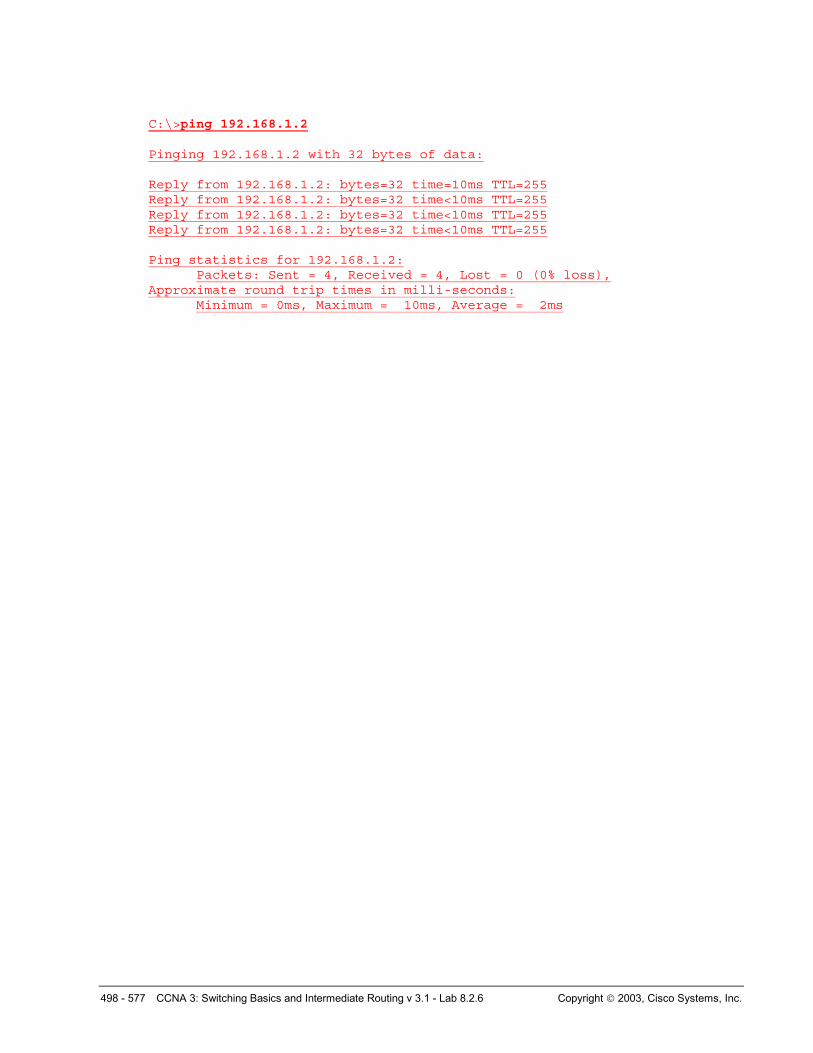
C:\>ping 192.168.1.2 Pinging 192.168.1.2 with 32 bytes of data: Reply from 192.168.1.2: bytes=32 time=10ms TTL=255 Reply from 192.168.1.2: bytes=32 time<10ms TTL=255 Reply from 192.168.1.2: bytes=32 time<10ms TTL=255 Reply from 192.168.1.2: bytes=32 time<10ms TTL=255 Ping statistics for 192.168.1.2:
Packets: Sent = 4, Received = 4, Lost = 0 (0% loss), Approximate round trip times in milli-seconds:
Minimum = 0ms, Maximum = 10ms, Average = 2ms
499 - 577 CCNA 3: Switching Basics and Intermediate Routing v 3.1 - Lab 8.2.6 Copyright 2003, Cisco Systems, Inc.
Erasing and Reloading the Switch For the majority of the labs in CCNA 3 and CCNA 4 it is necessary to start with an unconfigured switch. Use of a switch with an existing configuration may produce unpredictable results. These instructions allow preparation of the switch prior to performing the lab so previous configuration options do not interfere. The following is the procedure for clearing out previous configurations and starting with an unconfigured switch. Instructions are provided for the 2900, 2950, and 1900 Series switches.
2900 and 2950 Series Switches
1. Enter into the Privileged EXEC mode by typing enable.
If prompted for a password, enter class (if that does not work, ask the instructor).
Switch>enable
2. Remove the VLAN database information file.
Switch#delete flash:vlan.dat Delete filename [vlan.dat]?[Enter] Delete flash:vlan.dat? [confirm] [Enter]
If there was no VLAN file, this message is displayed.
%Error deleting flash:vlan.dat (No such file or directory)
3. Remove the switch startup configuration file from NVRAM.
Switch#erase startup-config
The responding line prompt will be:
Erasing the nvram filesystem will remove all files! Continue? [confirm]
Press Enter to confirm.
The response should be:
Erase of nvram: complete
4. Check that VLAN information was deleted.
Verify that the VLAN configuration was deleted in Step 2 using the show vlan command. If previous VLAN configuration information (other than the default management VLAN 1) is still present it will be necessary to power cycle the switch (hardware restart) instead of issuing the reload command. To power cycle the switch, remove the power cord from the back of the switch or unplug it. Then plug it back in.
If the VLAN information was successfully deleted in Step 2, go to Step 5 and restart the switch using the reload command.
5. Software restart (using the reload command)
500 - 577 CCNA 3: Switching Basics and Intermediate Routing v 3.1 - Lab 8.2.6 Copyright 2003, Cisco Systems, Inc.
Note: This step is not necessary if the switch was restarted using the power cycle method.
a. At the Privileged EXEC mode enter the command reload.
Switch#reload
The responding line prompt will be:
System configuration has been modified. Save? [yes/no]:
b. Type n and then press Enter.
The responding line prompt will be:
Proceed with reload? [confirm] [Enter]
The first line of the response will be:
Reload requested by console.
After the switch has reloaded, the line prompt will be:
Would you like to enter the initial configuration dialog? [yes/no]:
c. Type n and then press Enter.
The responding line prompt will be:
Press RETURN to get started! [Enter]
1900 Series Switches
1. Remove VLAN Trunking Protocol (VTP) information.
#delete vtp This command resets the switch with VTP parameters set to factory defaults. All other parameters will be unchanged. Reset system with VTP parameters set to factory defaults, [Y]es or [N]o?
Enter y and press Enter.
2. Remove the switch startup configuration from NVRAM.
#delete nvram
This command resets the switch with factory defaults. All system parameters will revert to their default factory settings. All static and dynamic addresses will be removed.
Reset system with factory defaults, [Y]es or [N]o?
Enter y and press Enter.