Embed Size (px)
Citation preview
Lamellar Structure Stability of a Two-Phase ¡-Mg/C14Mg2Ca Alloy+1
Shuntaro Abe+2, Koji Oishi+3 and Yoshihiro Terada+4
Department of Materials Science and Engineering, School of Materials and Chemical Technology, Tokyo Institute of Technology,Yokohama 226-8502, Japan
To evaluate the stability of ¡-Mg/C14Mg2Ca lamellar microstructure, aging treatment was carried out for a Mg14.8mass% Ca near-eutectic alloy at 573723K for 1150 hours. The spacing of the lamellar microstructure obtained by the eutectic transformation L ¼¡-Mg + C14Mg2Ca during solidification was approximately 250 nm. High-resolution transmission electron microscopy observations show thatthe ¡/C14 interface is composed of terraces and steps, with terraces parallel to the ð�1101Þ¡ pyramidal plane of the ¡-Mg lamellae. The ¡/C14lamellar microstructure is stable in morphology at temperatures below 573K. In contrast, the lamellar spacing () continuously increases withincreasing aging time (t) above 573K, and the increase in can be described as 2 ¹ 0
2 = kTt, where 0 is the ¡/C14 lamellar spacing for theas-cast specimen, and kT is a constant depending on aging temperature. The activation energy for the coarsening of ¡/C14 lamellarmicrostructure was evaluated as 112 kJ/mol, which is close to the activation energy for the inter-diffusion of Ca in Mg. The hardness of the¡/C14 lamellar region decreases with increasing , indicating that the ¡/C14 interface acts as an obstacle to the basal slip of dislocations in¡-Mg lamellae. [doi:10.2320/matertrans.MT-M2020376]
(Received December 16, 2020; Accepted January 20, 2021; Published February 26, 2021)
Keywords: magnesiumcalcium alloy, eutectic, C14Mg2Ca, interface, hardness
1. Introduction
Magnesium alloys are gaining interest as lightweightstructural metallic materials in the automotive and aerospaceindustries, where they are instrumental in increasing fuelefficiency and thus minimizing carbon dioxide emissions. Todate, however, their use has been chiefly limited to room-temperature components, except for pioneering applicationsfor automobile engine blocks.1) The development of heat-resistant magnesium alloys for automotive and aerospacecomponents is a key requirement for the widespread use ofthese alloys in promoting weight reduction and achievinghigh fuel efficiency for transportation equipment.24) Gen-erally, intermetallic phases are resistant to deformationbecause of their stronger covalent bonds compared to thoseof matrix magnesium.5) Maximum utilization of thermallystable intermetallic phases is therefore the critical requisitefor the enhancement of high-temperature strength in heat-resistant magnesium alloys.6,7)
The MgAlCa ternary system is a promising alloy systemfor developing lightweight, high-strength, heat-resistantmagnesium alloys with excellent cost performance.8,9) Toachieve widespread use of the MgAlCa alloys in high-temperature components, basic knowledge concerning high-temperature strength, for example precipitation behaviorduring aging,1013) high-temperature creep properties,1417)
and dislocation substructure during high-temperature defor-mation18,19) has been extensively investigated for thesealloys. When the MgAlCa ternary alloys are melted and
cast in the ¡-Mg solidification region, three kinds ofintermetallic compounds can be generated in the eutecticstructures formed during solidification: A12Mg17Al12, C14Mg2Ca, and C36(Mg,Al)2Ca.20) Of these three intermetallicphases, C14Mg2Ca offers the following advantages overA12Mg17Al12 and C36(Mg,Al)2Ca for improving creepstrength:21) (i) C14Mg2Ca is a thermally stable Daltonidecompound with a higher melting point; (ii) the fine lamellarmorphology of the C14Mg2Ca phase obtained by theeutectic transformation L¼ ¡-Mg + C14Mg2Ca precipi-tates at grain boundaries and covers primary ¡-Mg grains.
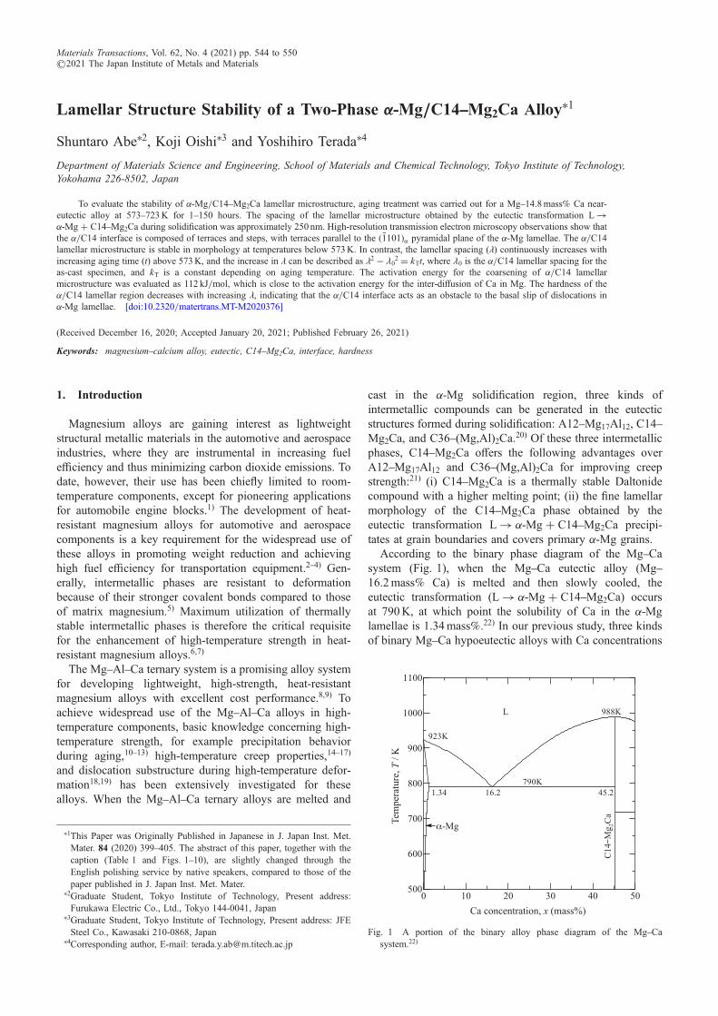
According to the binary phase diagram of the MgCasystem (Fig. 1), when the MgCa eutectic alloy (Mg16.2mass% Ca) is melted and then slowly cooled, theeutectic transformation (L ¼ ¡-Mg + C14Mg2Ca) occursat 790K, at which point the solubility of Ca in the ¡-Mglamellae is 1.34mass%.22) In our previous study, three kindsof binary MgCa hypoeutectic alloys with Ca concentrations
0 10 20 30 40 50500
600
700
800
900
1000
1100
923K
1.34
988K
790K16.2 45.2
-Mg
Ca concentration, x (mass%)
Tem
pera
ture
, T /
K
L
C14
Mg 2
Ca
Fig. 1 A portion of the binary alloy phase diagram of the MgCasystem.22)
+1This Paper was Originally Published in Japanese in J. Japan Inst. Met.Mater. 84 (2020) 399405. The abstract of this paper, together with thecaption (Table 1 and Figs. 110), are slightly changed through theEnglish polishing service by native speakers, compared to those of thepaper published in J. Japan Inst. Met. Mater.
+2Graduate Student, Tokyo Institute of Technology, Present address:Furukawa Electric Co., Ltd., Tokyo 144-0041, Japan
+3Graduate Student, Tokyo Institute of Technology, Present address: JFESteel Co., Kawasaki 210-0868, Japan
+4Corresponding author, E-mail: [email protected]
Materials Transactions, Vol. 62, No. 4 (2021) pp. 544 to 550©2021 The Japan Institute of Metals and Materials
of 2.814.8mass% were prepared, and the effect of ¡-Mg/C14Mg2Ca lamellar fraction on high-temperature creepstrength was quantitatively evaluated at creep conditionsof 473K and 40MPa.23) Thus, the following two pointswere clarified: (i) the creep curves of the binary MgCahypoeutectic alloys showed minimum creep rates after thenormal transition creep region, resulting in rupture via theaccelerating creep region; (ii) the minimum creep rate wassmaller and the rupture life was prolonged with increasing¡/C14 lamellar fraction at higher Ca concentration.Increasing the ¡/C14 interface area by increasing thelamellar fraction in the microstructure can be an effectiveway to enhance the high-temperature creep strength of binaryMgCa cast alloys. The aims of the present work are to (i)clarify the crystallographic orientation relationship between¡-Mg lamellae and the ¡/C14 interface and (ii) specify thetemperature region in which the ¡/C14 lamellar micro-structure is stable in morphology. The present study thusprovides basic knowledge required for discussing high-temperature creep strength for the two-phase ¡-Mg/C14Mg2Ca eutectic alloy with lamellar microstructure. It is notedthat a binary MgCa hypoeutectic alloy with a compositionclose to the eutectic composition was used as a test materialin this study to preclude the appearance of the brittle primaryC14Mg2Ca phase.
2. Experimental
Two kinds of binary MgCa hypoeutectic alloys with alloycompositions close to the eutectic composition (Mg16.2mass% Ca) were used in this study: Mg14.8mass% Ca(Alloy A) and Mg13.8mass% Ca (Alloy B). Blocks ofthese alloys with dimensions of 100 © 160 © 20mm3 weregravity-cast by the permanent mold-casting method witha mild steel mold under argon atmosphere using easilyavailable starting materials of the highest purity, with thecasting temperature set at 1053K. Cubic specimens withdimensions of 8 © 8 © 8mm3 were cut out from the blocksand were then subjected to aging treatment in air in thetemperature range of 573723K for 3.6 © 103 to 5.4 © 105
seconds (i.e., 1150 hours).The microstructures of the as-cast and aged samples were
studied using optical microscopy (OM), field-emissionscanning electron microscopy (FE-SEM), and high-resolutiontransmission electron microscopy (HRTEM). Specimensmounted in resin for OM and FE-SEM observations werepolished mechanically with emery paper and alumina slurryand were then etched in a solution of 2 vol% HNO3 and98 vol% ethyl alcohol for 2 seconds. For HRTEM micro-structure observations, thin films cut out from the cubic testpiece were shaped into disc-shaped samples with a diameterof 3mm and a thickness of 120 µm. The discs were furtherthinned by mechanical polishing, followed by dimplegrinding and ion-milling, to perforate the center portion ofthe discs. The perforated discs were examined using a Cs-corrected scanning transmission electron microscope (FEITitan3 G2 60-300) operating at 300 kV.
Hardness measurements were conducted using a microVickers hardness tester; the load was set at 4.9N, and theholding time was constant at 10 seconds. For both the as-cast
and aged specimens, seven measurements were conducted,and the hardness was determined from the average of thefive measurements remaining once the maximum andminimum values were excluded. It is noted that Alloys Aand B were regarded as essentially interchangeable in thisstudy; Alloy B was used only for HRTEM observation, whileAlloy A was used for all the other experiments.
3. Results and Discussion
3.1 Observation of ¡-Mg/C14Mg2Ca lamellar micro-structure
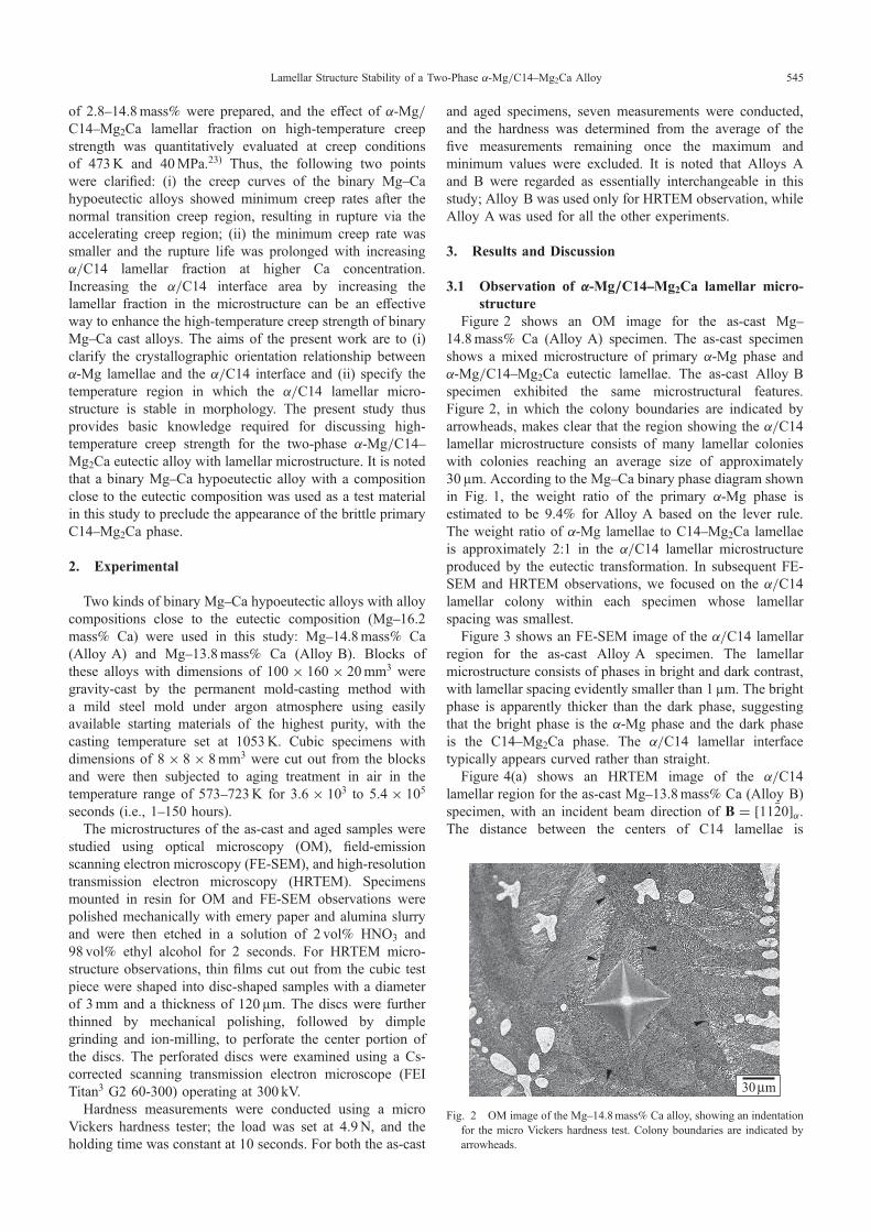
Figure 2 shows an OM image for the as-cast Mg14.8mass% Ca (Alloy A) specimen. The as-cast specimenshows a mixed microstructure of primary ¡-Mg phase and¡-Mg/C14Mg2Ca eutectic lamellae. The as-cast Alloy Bspecimen exhibited the same microstructural features.Figure 2, in which the colony boundaries are indicated byarrowheads, makes clear that the region showing the ¡/C14lamellar microstructure consists of many lamellar colonieswith colonies reaching an average size of approximately30 µm. According to the MgCa binary phase diagram shownin Fig. 1, the weight ratio of the primary ¡-Mg phase isestimated to be 9.4% for Alloy A based on the lever rule.The weight ratio of ¡-Mg lamellae to C14Mg2Ca lamellaeis approximately 2:1 in the ¡/C14 lamellar microstructureproduced by the eutectic transformation. In subsequent FE-SEM and HRTEM observations, we focused on the ¡/C14lamellar colony within each specimen whose lamellarspacing was smallest.
Figure 3 shows an FE-SEM image of the ¡/C14 lamellarregion for the as-cast Alloy A specimen. The lamellarmicrostructure consists of phases in bright and dark contrast,with lamellar spacing evidently smaller than 1 µm. The brightphase is apparently thicker than the dark phase, suggestingthat the bright phase is the ¡-Mg phase and the dark phaseis the C14Mg2Ca phase. The ¡/C14 lamellar interfacetypically appears curved rather than straight.
Figure 4(a) shows an HRTEM image of the ¡/C14lamellar region for the as-cast Mg13.8mass% Ca (Alloy B)specimen, with an incident beam direction of B ¼ ½11�20�¡.The distance between the centers of C14 lamellae is
30 μm
Fig. 2 OM image of the Mg14.8mass% Ca alloy, showing an indentationfor the micro Vickers hardness test. Colony boundaries are indicated byarrowheads.
Lamellar Structure Stability of a Two-Phase ¡-Mg/C14Mg2Ca Alloy 545

approximately 250 nm, and terraces and steps alternate alongthe curved ¡/C14 interface as indicated by white arrowheads.In addition, terraces and steps are densely concentrated at theend of the C14 lamella as indicated by black arrowheads.Figure 4(b) shows an magnified HRTEM image of the region
surrounded by the square in Fig. 4(a), in which the ¡/C14interface is viewed edge-on. It is evident at highmagnification that the terraces approximately 30 nm in lengthand the steps approximately 3 nm in height alternate alongthe interface, even if the interface looks smooth at lowmagnification. Figure 5 shows the STEM bright-field imageof a terrace along the ¡/C14 lamellar interface, together withthe selected-area diffraction pattern (SADP) of the ¡-Mglamellae. The terrace along the ¡/C14 interface is parallel tothe ð�1101Þ¡ pyramidal plane of the ¡-Mg lamellae, and the(0001)¡ basal plane, which is the primary slip plane of thehcp crystal, is oriented toward the ¡/C14 interface.
3.2 Thermal stability of ¡-Mg/C14Mg2Ca lamellarmicrostructure
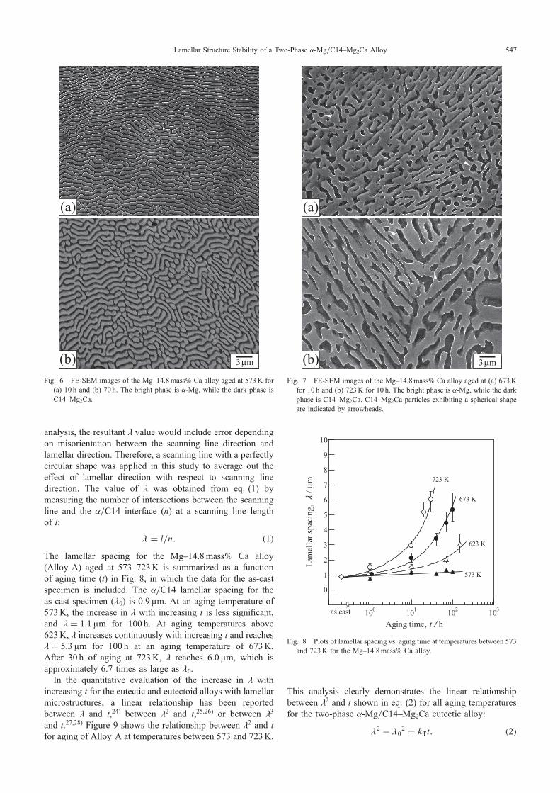
In order to specify the temperature region in which the¡/C14 lamellar microstructure is stable in morphology, agingtreatment was carried out for the Mg14.8mass% Ca alloy(Alloy A) at temperatures between 573 and 723K, followedby FE-SEM microstructure observation. Figure 6 showsFE-SEM images of the ¡/C14 lamellar region for Alloy Aaged at 573K, which is approximately 0.73 times the eutectictemperature Teut of 790K. The lamellar spacing for thespecimen aged for 10 h (Fig. 6(a)) is apparently submicron,as is the case for the as-cast specimen (Fig. 3). The finelamellar microstructure remains unchanged even in thespecimen aged for 70 h (Fig. 6(b)). These results suggestthat the ¡/C14 lamellar microstructure is stable inmorphology in the temperature range below 573K.
Figure 7 shows FE-SEM images for the alloys aged attemperatures above 673K. In the specimen aged at 673K(³0.85Teut) for 10 h, the ¡/C14 lamellar spacing is apparentlylarger than in the as-cast specimen (Fig. 3), and a portionof the C14 lamellae evolve to a spherical morphology asindicated by arrowheads as shown in Fig. 7(a). In thespecimen aged at 723K (³0.92Teut) for 10 h, the lamellarspacing is further increased compared to the specimen agedat 673K for 10 h while still retaining the lamellar micro-structure as shown in Fig. 7(b).
The ¡/C14 lamellar spacing () for the aged specimenswas quantified from the FE-SEM images using linearanalysis. If a straight scanning line was applied in such an
3 μm
Fig. 3 FE-SEM image of ¡-Mg/C14Mg2Ca lamellar microstructureobserved in the Mg14.8mass% Ca alloy. The bright phase is ¡-Mg,while the dark phase is C14Mg2Ca.
(b) 20 nm
C14
(a) 100 nm
Fig. 4 HRTEM image, taken with B ¼ ½11�20�¡, of ¡-Mg/C14Mg2Calamellar microstructure observed in the Mg13.8mass% Ca alloy (a). In(a), steps at the ¡/C14 interface are indicated by arrowheads. The areasurrounded by the square in (a) is magnified in (b).
2 nm
C14
(0001)
1101
00000001
Fig. 5 STEM BFI of an ¡-Mg/C14Mg2Ca terrace in the Mg13.8mass%Ca alloy, together with SADP taken with B ¼ ½11�20�¡.
S. Abe, K. Oishi and Y. Terada546
analysis, the resultant value would include error dependingon misorientation between the scanning line direction andlamellar direction. Therefore, a scanning line with a perfectlycircular shape was applied in this study to average out theeffect of lamellar direction with respect to scanning linedirection. The value of was obtained from eq. (1) bymeasuring the number of intersections between the scanningline and the ¡/C14 interface (n) at a scanning line lengthof l:
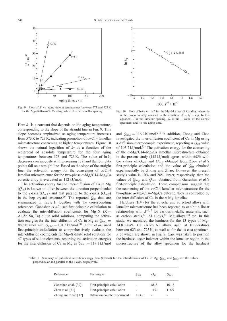
¼ l=n: ð1ÞThe lamellar spacing for the Mg14.8mass% Ca alloy(Alloy A) aged at 573723K is summarized as a functionof aging time (t) in Fig. 8, in which the data for the as-castspecimen is included. The ¡/C14 lamellar spacing for theas-cast specimen (0) is 0.9 µm. At an aging temperature of573K, the increase in with increasing t is less significant,and = 1.1 µm for 100 h. At aging temperatures above623K, increases continuously with increasing t and reaches = 5.3 µm for 100 h at an aging temperature of 673K.After 30 h of aging at 723K, reaches 6.0 µm, which isapproximately 6.7 times as large as 0.
In the quantitative evaluation of the increase in withincreasing t for the eutectic and eutectoid alloys with lamellarmicrostructures, a linear relationship has been reportedbetween and t,24) between 2 and t,25,26) or between 3
and t.27,28) Figure 9 shows the relationship between 2 and tfor aging of Alloy A at temperatures between 573 and 723K.
This analysis clearly demonstrates the linear relationshipbetween 2 and t shown in eq. (2) for all aging temperaturesfor the two-phase ¡-Mg/C14Mg2Ca eutectic alloy:
2 � 02 ¼ kTt: ð2Þ
(b) 3 μm
(a)
Fig. 6 FE-SEM images of the Mg14.8mass% Ca alloy aged at 573K for(a) 10 h and (b) 70 h. The bright phase is ¡-Mg, while the dark phase isC14Mg2Ca.
(b) 3 μm
(a)
Fig. 7 FE-SEM images of the Mg14.8mass% Ca alloy aged at (a) 673Kfor 10 h and (b) 723K for 10 h. The bright phase is ¡-Mg, while the darkphase is C14Mg2Ca. C14Mg2Ca particles exhibiting a spherical shapeare indicated by arrowheads.
100 101 102 103
0
1
2
3
4
5
6
7
8
9
10
Aging time, t / h
Lam
ella
r spa
cing
, λ
/ μm
as cast
723 K
623 K
573 K
673 K
Fig. 8 Plots of lamellar spacing vs. aging time at temperatures between 573and 723K for the Mg14.8mass% Ca alloy.
Lamellar Structure Stability of a Two-Phase ¡-Mg/C14Mg2Ca Alloy 547
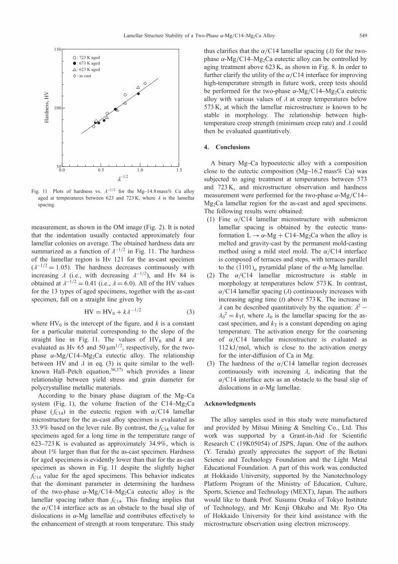
Here kT is a constant that depends on the aging temperature,corresponding to the slope of the straight line in Fig. 9. Thisslope becomes emphasized as aging temperature increasesfrom 573K to 723K, indicating promotion of ¡/C14 lamellarmicrostructure coarsening at higher temperatures. Figure 10shows the natural logarithm of kT as a function of thereciprocal of absolute temperature for the four agingtemperatures between 573 and 723K. The value of ln kTdecreases continuously with increasing 1/T, and the four datapoints fall on a straight line. Based on the slope of the straightline, the activation energy for the coarsening of ¡/C14lamellar microstructure for the two-phase ¡-Mg/C14Mg2Caeutectic alloy is evaluated as 112 kJ/mol.
The activation energy for the inter-diffusion of Ca in Mg(Qint) is known to differ between the direction perpendicularto the c-axis (Qint¦) and that parallel to the c-axis (Qint//)in the hcp crystal structure.29) The reported Qint data aresummarized in Table 1, together with the correspondingreferences. Ganeshan et al. used first-principle calculation toevaluate the inter-diffusion coefficients for MgX (X =Al, Zn, Sn, Ca) dilute solid solutions, computing the activa-tion energies for the inter-diffusion of Ca in Mg as Qint¦ =88.8 kJ/mol and Qint// = 101.3 kJ/mol.30) Zhou et al. usedfirst-principle calculation to comprehensively evaluate theinter-diffusion coefficients for MgX dilute solid solutions for47 types of solute elements, reporting the activation energiesfor the inter-diffusion of Ca in Mg as Qint¦ = 119.1 kJ/mol
and Qint// = 116.9 kJ/mol.31) In addition, Zhong and Zhaoinvestigated the inter-diffusion coefficient of Ca in Mg usinga diffusionthermocouple experiment, reporting a Qint valueof 103.7 kJ/mol.32) The activation energy for the coarseningof the ¡-Mg/C14Mg2Ca lamellar microstructure obtainedin the present study (112 kJ/mol) agrees within «8% withthe values of Qint¦ and Qint// obtained from Zhou et al.’sfirst-principle calculation and the value of Qint obtainedexperimentally by Zhong and Zhao. However, the presentstudy’s value is 10% and 26% larger, respectively, than thevalues of Qint// and Qint¦ obtained from Ganeshan et al.’sfirst-principle calculation. These comparisons suggest thatthe coarsening of the ¡/C14 lamellar microstructure for thetwo-phase ¡-Mg/C14Mg2Ca eutectic alloy is controlled bythe inter-diffusion of Ca in the ¡-Mg lamellae.
Hardness (HV) for the eutectic and eutectoid alloys withlamellar microstructure has been reported to exhibit a linearrelationship with ¹1/2 for various metallic materials, suchas carbon steels,33) Al alloys,34) Mg alloys,35) etc. In thisstudy, we measured the hardness for the 13 types of Mg14.8mass% Ca (Alloy A) alloys aged at temperaturesbetween 623 and 723K, as well as for the as-cast specimen, of which are shown in Fig. 8. Care was taken to positionthe hardness tester indenter within the lamellar region in themicrostructure of the alloy specimen for the hardness
0 50 100 150 2000
10
20
30
40
50
Aging time, t / h
2 / m−1
2
723 K
673 K
623 K
573 K
Fig. 9 Plots of 2 vs. aging time at temperatures between 573 and 723Kfor the Mg14.8mass% Ca alloy, where is the lamellar spacing.
Table 1 Summary of published activation energy data (kJ/mol) for the inter-diffusion of Ca in Mg. Qint¦ and Qint// are the valuesperpendicular and parallel to the c-axis, respectively.
112 kJ/mol
1.2 1.3 1.4 1.5 1.6 1.7 1.8 1.910
5
0
5
1000 T 1 / K 1
ln k
T
Fig. 10 Plots of ln kT vs. 1/T for the Mg14.8mass% Ca alloy, where kTis the proportionality constant in the equation: 2 ¹ 0
2 = kTt. In thisequation, is the lamellar spacing, 0 is the value of the as-castspecimen, and t is the aging time.
S. Abe, K. Oishi and Y. Terada548
measurement, as shown in the OM image (Fig. 2). It is notedthat the indentation usually contacted approximately fourlamellar colonies on average. The obtained hardness data aresummarized as a function of ¹1/2 in Fig. 11. The hardnessof the lamellar region is Hv 121 for the as-cast specimen(¹1/2 = 1.05). The hardness decreases continuously withincreasing (i.e., with decreasing ¹1/2), and Hv 84 isobtained at ¹1/2 = 0.41 (i.e., = 6.0). All of the HV valuesfor the 13 types of aged specimens, together with the as-castspecimen, fall on a straight line given by
HV ¼ HV0 þ k�1=2 ð3Þwhere HV0 is the intercept of the figure, and k is a constantfor a particular material corresponding to the slope of thestraight line in Fig. 11. The values of HV0 and k areevaluated as Hv 65 and 50 µm1/2, respectively, for the two-phase ¡-Mg/C14Mg2Ca eutectic alloy. The relationshipbetween HV and in eq. (3) is quite similar to the well-known HallPetch equation,36,37) which provides a linearrelationship between yield stress and grain diameter forpolycrystalline metallic materials.
According to the binary phase diagram of the MgCasystem (Fig. 1), the volume fraction of the C14Mg2Caphase ( fC14) in the eutectic region with ¡/C14 lamellarmicrostructure for the as-cast alloy specimen is evaluated as33.9% based on the lever rule. By contrast, the fC14 value forspecimens aged for a long time in the temperature range of623723K is evaluated as approximately 34.9%, which isabout 1% larger than that for the as-cast specimen. Hardnessfor aged specimens is evidently lower than that for the as-castspecimen as shown in Fig. 11 despite the slightly higherfC14 value for the aged specimens. This behavior indicatesthat the dominant parameter in determining the hardnessof the two-phase ¡-Mg/C14Mg2Ca eutectic alloy is thelamellar spacing rather than fC14. This finding implies thatthe ¡/C14 interface acts as an obstacle to the basal slip ofdislocations in ¡-Mg lamellae and contributes effectively tothe enhancement of strength at room temperature. This study
thus clarifies that the ¡/C14 lamellar spacing () for the two-phase ¡-Mg/C14Mg2Ca eutectic alloy can be controlled byaging treatment above 623K, as shown in Fig. 8. In order tofurther clarify the utility of the ¡/C14 interface for improvinghigh-temperature strength in future work, creep tests shouldbe performed for the two-phase ¡-Mg/C14Mg2Ca eutecticalloy with various values of at creep temperatures below573K, at which the lamellar microstructure is known to bestable in morphology. The relationship between high-temperature creep strength (minimum creep rate) and couldthen be evaluated quantitatively.
4. Conclusions
A binary MgCa hypoeutectic alloy with a compositionclose to the eutectic composition (Mg16.2mass% Ca) wassubjected to aging treatment at temperatures between 573and 723K, and microstructure observation and hardnessmeasurement were performed for the two-phase ¡-Mg/C14Mg2Ca lamellar region for the as-cast and aged specimens.The following results were obtained:(1) Fine ¡/C14 lamellar microstructure with submicron
lamellar spacing is obtained by the eutectic trans-formation L¼ ¡-Mg + C14Mg2Ca when the alloy ismelted and gravity-cast by the permanent mold-castingmethod using a mild steel mold. The ¡/C14 interfaceis composed of terraces and steps, with terraces parallelto the ð�1101Þ¡ pyramidal plane of the ¡-Mg lamellae.
(2) The ¡/C14 lamellar microstructure is stable inmorphology at temperatures below 573K. In contrast,¡/C14 lamellar spacing () continuously increases withincreasing aging time (t) above 573K. The increase in can be described quantitatively by the equation: 2 ¹0
2 = kTt, where 0 is the lamellar spacing for the as-cast specimen, and kT is a constant depending on agingtemperature. The activation energy for the coarseningof ¡/C14 lamellar microstructure is evaluated as112 kJ/mol, which is close to the activation energyfor the inter-diffusion of Ca in Mg.
(3) The hardness of the ¡/C14 lamellar region decreasescontinuously with increasing , indicating that the¡/C14 interface acts as an obstacle to the basal slip ofdislocations in ¡-Mg lamellae.
Acknowledgments
The alloy samples used in this study were manufacturedand provided by Mitsui Mining & Smelting Co., Ltd. Thiswork was supported by a Grant-in-Aid for ScientificResearch C (19K05054) of JSPS, Japan. One of the authors(Y. Terada) greatly appreciates the support of the IketaniScience and Technology Foundation and the Light MetalEducational Foundation. A part of this work was conductedat Hokkaido University, supported by the NanotechnologyPlatform Program of the Ministry of Education, Culture,Sports, Science and Technology (MEXT), Japan. The authorswould like to thank Prof. Susumu Onaka of Tokyo Instituteof Technology, and Mr. Kenji Ohkubo and Mr. Ryo Otaof Hokkaido University for their kind assistance with themicrostructure observation using electron microscopy.
0.0 0.5 1.0 1.550
100
150H
ardn
ess,
HV
λ−1/2
: as cast: 623 K aged: 673 K aged: 723 K aged
Fig. 11 Plots of hardness vs. ¹1/2 for the Mg14.8mass% Ca alloyaged at temperatures between 623 and 723K, where is the lamellarspacing.
Lamellar Structure Stability of a Two-Phase ¡-Mg/C14Mg2Ca Alloy 549
REFERENCES
1) B.L. Mordike and T. Ebert: Mater. Sci. Eng. A 302 (2001) 3745.2) A.A. Luo, M.P. Balogh and B.R. Powell: Metall. Mater. Trans. A 33
(2002) 567574.3) V. Sklenička, M. Pahutová, K. Kuchařová, M. Svoboda and T.G.
Langdon: Metall. Mater. Trans. A 33 (2002) 883889.4) S.M. Zhu, M.A. Gibson, M.A. Easton and J.F. Nie: Scr. Mater. 63
(2010) 698703.5) S.S. Vagarali and T.G. Langdon: Acta Metall. 29 (1981) 19691982.6) N. Hort, Y. Huang and U. Kainer: Adv. Eng. Mater. 8 (2006) 235240.7) M. Zubair, S. Sandlobes, M.A. Wollenweber, C.F. Kusche, W.
Hildebrandt, C. Broeckmann and S. Korte-Kerzel: Mater. Sci. Eng. A756 (2019) 272283.
8) A. Suzuki, N.D. Saddock, J.W. Jones and T.M. Pollock: Metall. Mater.Trans. A 37 (2006) 975983.
9) A.A. Luo, B.R. Powell and A.K. Sachdev: Intermetallics 24 (2012) 2229.
10) A. Suzuki, N.D. Saddock, J.R. TerBush, B.R. Powell, J.W. Jones andT.M. Pollock: Metall. Mater. Trans. A 39 (2008) 696702.
11) J.-F. Nie: Metall. Mater. Trans. A 43 (2012) 38913939.12) A. Nomoto, S. Kashiwase, K. Nakagawa, H. Hisazawa and Y. Terada:
J. Japan Inst. Met. Mater. 82 (2018) 94101.13) S. Kashiwase, M. Unekawa, H. Hisazawa and Y. Terada: Mater. Trans.
61 (2020) 375380.14) Y. Terada, N. Ishimatsu and T. Sato: Mater. Trans. 48 (2007) 2329
2335.15) S.M. Zhu, B.L. Mordike and J.F. Nie: Mater. Sci. Eng. A 483484
(2008) 583586.16) T. Homma, S. Nakawaki, K. Oh-ishi, K. Hono and S. Kamado: Acta
Mater. 59 (2011) 76627672.17) Y. Terada, Y. Murata and T. Sato: Mater. Sci. Eng. A 613 (2014) 136
140.
18) J.R. TerBush, A. Suzuki, N.D. Saddock, J.W. Jones and T.M. Pollock:Scr. Mater. 58 (2008) 914917.
19) Y. Terada, Y. Murata and T. Sato: J. Japan Inst. Met. Mater. 77 (2013)391397.
20) A. Suzuki, N.D. Saddock, J.W. Jones and T.M. Pollock: Acta Mater. 53(2005) 28232834.
21) Y. Terada, M. Tsukahara, A. Shibayama, Y. Murata and M. Morinaga:Scr. Mater. 64 (2011) 10391042.
22) T.B. Massalski (ed.): Binary Alloy Phase Diagrams, 2nd ed., (ASMInternational, Materials Park, OH, 1990).
23) A. Shibayama, Y. Terada, Y. Murata and M. Morinaga: Mater. Trans. 51(2010) 22842288.
24) L.D. Graham and R.W. Kraft: Trans. Metall. AIME 236 (1966) 94102.25) H.E. Cline: Acta Metall. 19 (1971) 481490.26) I. Baker and F. Meng: Acta Mater. 95 (2015) 124131.27) K. Ishida, M. Ohkubo, M.Y. Wey and T. Nishizawa: J. Japan Inst.
Metals 52 (1988) 388394.28) X. Li, F. Bottler, R. Spatschek, A. Schmitt, M. Heilmaier and F. Stein:
Acta Mater. 127 (2017) 230243.29) J. Combronde and G. Brebec: Acta Metall. 19 (1971) 13931399.30) S. Ganeshan, L.G. Hector, Jr. and Z.-K. Liu: Acta Mater. 59 (2011)
32143228.31) B.-C. Zhou, S.-L. Shang, Y. Wang and Z.-K. Liu: Acta Mater. 103
(2016) 573586.32) W. Zhong and J.-C. Zhao: Scr. Mater. 127 (2017) 9296.33) K.K. Ray and D. Mondal: Acta Metall. Mater. 39 (1991) 22012208.34) Q. Lei, B.P. Ramakrishnan, S. Wang, Y. Wang, J. Mazumder and A.
Misra: Mater. Sci. Eng. A 706 (2017) 115125.35) J.-H. Jun: J. Alloy. Compd. 725 (2017) 237241.36) W.F. Hosford: Mechanical Behavior of Materials, 2nd ed., (Cambridge
University Press, Cambridge, 2010).37) W.D. Callister, Jr. and D.G. Rethwisch: Materials Science and
Engineering, 9th ed., (John Wiley & Sons, Hoboken, NJ, 2015).
S. Abe, K. Oishi and Y. Terada550