Embed Size (px)
Citation preview

Laser Diode Setup and Operation
Eric Lochbrunner
Diodes are a very important electrical component which can easily be found in most common circuits. The purpose of a diode is to control the flow of current. Laser diodes are complex semiconductors similar to regular diodes that convert an electrical current to light. They are essentially light emitting diodes (LED’s) with two mirrors on the surface of the diode to create laser activity. Light emitters are a key element in any fiber optic system.
As mentioned earlier, a regular diode is a simple electrical component that allow current to flow in only one direction. When you put N‐type and P‐type silicon together you get a very interesting phenomenon that gives the diode its unique properties.
The negative electrons on the N‐type side are attracted to the holes located on the P‐type side. When the proper bias is applied to the P‐N junction, these electrons and holes are able to move across the junction. This movement of electrons is electrical current.
A laser diode is a laser whose active medium is a semiconductor similar to that found in a LED. Similar to a regular diode, a laser diode also uses a P‐N junction and is powered by

injected electrical current. As in other lasers, the gain region of a laser diode is surrounded with an optical cavity to form a laser.
For this project, my task was to assemble and understand the laser diode system manufactured by ThorLabs. This involved understanding the laser diode controller (also manufactured by ThorLabs) and assembling a photodiode circuit to capture the emitted laser light. The measurements would be done using a digital voltage meter (DVM). There were some other peripheral circuits used that will be explained later.
Let’s begin by first explaining the Laser Diode Controller (LDC). The LDC‐500 laser diode controller is an extremely precise controller for laser diodes and LED’s. When used, the laser current or the optical output power and the temperature of the connected laser diode controller can be precisely regulated which allows the laser diode to operate as a stable optical system. For exact operation of the laser diode controller I will refer the reader to the operations manual. I will restrict explanation of the laser diode controller operation to only what was necessary to successfully connect and operate the laser diode.
Below you will see a picture of the front side of the LDC.
1 LED "LDA" Selected polarity of the laser: anode grounded 2 LED "LDC" Selected polarity of the laser: cathode grounded 3 4½-digit LCD display 4 LED "mA" Display is laser current (mA) 5 LED "mW" Display is laser power (mW) 6 LED "OPEN CKT" Indicates no laser diode connected 7 LED "LIMIT" Adjusted current limit reached 8 LED "ENABLE" Laser current is switched on

9 "ENABLE" Button Enables the laser current on or off 10 Knob for adjusting the set value 11 Line switch 12 LIM I Potentiometer for setting the current limit 13 CAL Potentiometer for calibrating the power display 14 LED "PLD" Displaying the optical output power 15 LED "IPD" Displaying the photodiode current 16 LED "ILD" Displaying the laser current 17 LED "ILIM" Displaying current limit 18 DOWN Button Used for selecting the display parameter 19 UP Button Used for selecting the display parameter 20 LED "P" Constant power mode 21 LED "I" Constant current mode 22 "P" Button Selecting constant power mode 23 "I" Button Selecting constant current mode 24 PD RANGE Potentiometer for setting the photodiode current range
Many of these functions will be explained throughout this paper since understanding them was necessary for successful connection of the laser diode.
The back of the LDC is shown below and will require some explanation also.
1 Modulation input/ analog control input "MOD IN" 2 Control Out (Laser Current Monitor) 3 Ventilation Fan 4 Connector for chassis ground 5 Connector "LD OUT" for laser diode, photodiode, interlock, status-LED (DB9F)

6 Switch "LD POL" for selecting the laser diode polarity 7 Serial number of the unit 8 Letter-plate displaying the allowed line voltage 9 IEC 320 AC power receptacle and fuse holder
Before operating a laser diode, it is imperative that we set the current limit to the desired maximum operating current of out laser. This was done as below:
Procedure to set ILIM
1. Switch the unit on with the “ON” button. 2. Select the parameter ILIM with buttons (18) or (19). 3. Use a small flat blade screwdriver to set the desired current by adjusting
LIM I (button 12).
At this point it is necessary to understand the polarity of the laser diode. This may require some configuration on the part of the user. Since there is both a laser diode and a photodiode present, we’ll have four different configuration options. Depending on which configuration you choose, you will need to connect the appropriate pins to ensure successful operation. Operation of the laser diode with the wrong polarity configuration can possibly destroy the laser diode, the photodiode or both!
If you need to have the diode configured to a specific polarity, you should familiarize yourself with the diagram below:

This diagram shows what type of connector will be used to connect the laser diode to the LDC. After you have an understanding of what pins will need to be utilized for your specific diode configuration needs, you can choose from one of the wiring configurations below.
These schematics show exactly the wiring necessary to achieve any desired configuration of laser diode and photodiode (there are only 4 possible configurations). For my part in this project, the configuration in the top left corner was selected. By using the schematic and the pin‐out diagram on the previous page, I was able to verify that that my system was wired the way I expected it to be.
Above is a picture of the connector after it was re‐soldered to match the configuration I needed. Hopefully, it is clear from the picture that the connections described in the schematic match the necessary connections listed in the connector pin‐out picture. You can see that pins 1 and 5 are connected together as well as pins 2 and 3. The wires from pin 4 and pin 7 run inside the housing to connect to the laser diode and photodiode.
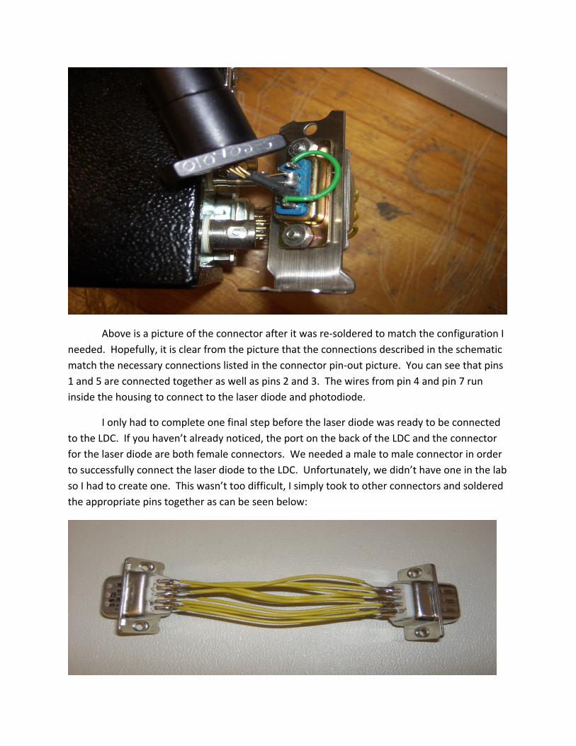
I only had to complete one final step before the laser diode was ready to be connected to the LDC. If you haven’t already noticed, the port on the back of the LDC and the connector for the laser diode are both female connectors. We needed a male to male connector in order to successfully connect the laser diode to the LDC. Unfortunately, we didn’t have one in the lab so I had to create one. This wasn’t too difficult, I simply took to other connectors and soldered the appropriate pins together as can be seen below:

After this was completed we were finally ready to connect the laser diode to the LDC. The only step that remained was to verify that the LDC had the correct settings.
From our preparations, and verifying with the schematic provided, we know that the anode of the laser diode and the cathode of the photodiode are grounded. We must, therefore ensure that the “LDA” LED is illuminated (this can be seen as (1) on the front‐side picture of the LDC shown earlier). This setting is actually controlled from the back of the LDC. There is a small switch which allows the user to select either “AG” (anode ground) or “CG” (cathode ground) for the laser diode polarity. This polarity switch can also be seen on the picture of the back of the LDC provided earlier in this paper. Once these settings were verified we used the connector, pictured above, to connect the laser diode to the laser diode controller.
Before we turn on the LDC, we should first setup the receiver side of our system. For this we’ll need a photodiode to detect the outputted laser, an amplifier to amplify that output, and finally a DVM to measure the signal from the amplifier.
We’ll first discuss the photodiode. The photodiode that we’ll be using is an ETX series InGaAs photodiode from JDSU Inc.
To eliminate confusion it should be noted that a normal diode only has two pins, but the photodiode above has three. This third pin is a ground pin for electrostatic discharge which protects the photodiode. There some prep work we’ll need to do before we are ready to use this component.
We will solder the photodiode shown above to a BNC connector. To do this we will be sure to solder pin one to ground and pins two and three together with a current path to the amplifier. After this soldering is complete, it will look like this.

We can now connect the photodiode to the current amplifier by using a BNC cable. The amplifier we will use is the SR570 Current Preamplifier. This preamp will allow for a BNC input connection and also gives us the option for a BNC output.
A picture of the current preamplifier we will use can be seen below.
In the above picture you can see the BNC input and output connections. The BNC output will make for an easy connection to the DVM we will use to verify that out total system works correctly.
Now that we are familiar with all of the components of our system we can activate the system and take some measurements!
As mentioned earlier, when we turn on the LDC we will need to set the limit current and also decide which mode of operation we wish to use (Constant Current or Constant Power).

Either mode of operation will be successful in giving us a laser output. For simplicity, we will describe the operation of the LDC in constant current mode.
First, switch on the LDC. Then select the appropriate laser diode polarity (for this case, it is Anode
Ground). We will then connect the laser diode and select the display “ILD” on the
front of the LDC. Set the adjust knob by turning it completely counter‐clockwise. Press the “I” button to select constant current mode. Switch on the output by pressing the “ENABLE” button. With the adjust knob, the laser current can be set continuously between
0mA and the current limit “ILIM”.
Following the steps above will give a laser output generated by the laser diode.
We will now setup the preamplifier so that out laser output can be read.
First, before we turn on the current preamplifier, press the “Filter Reset” button on the front of the preamp and hold it down while simultaneously turning on the preamp with the ON/OFF button.
Connect the photodiode to the preamp input using a BNC cable Connect another BNC cable from the preamp output to the DVM that will
be used to verify system operation.
If you have hooked the system up correctly, you should see a voltage on the readout of the DVM as shown below.

It should be noted that the reason there is a negative voltage shown above is because we connected the BNC to the DVM backwards. If we switch the connections, which will change the polarity, the number will appear positive.
The final system will look like
this:

In conclusion, this project was helpful in understanding all of the intricacies involved in successfully setting up a laser diode and, also, a photodiode to receive the output. There were many details that needed attention that were not initially obvious for this system. The operation manual for the LDC was invaluable in helping me to complete this project and will be crucial for anyone wishing to use this system in the future. It was proven that, if setup correctly, this system will indeed give a voltage output which can be read with a digital volt meter. I hope that anyone who uses this system in the future has as much fun with it as I did.