Embed Size (px)
Citation preview
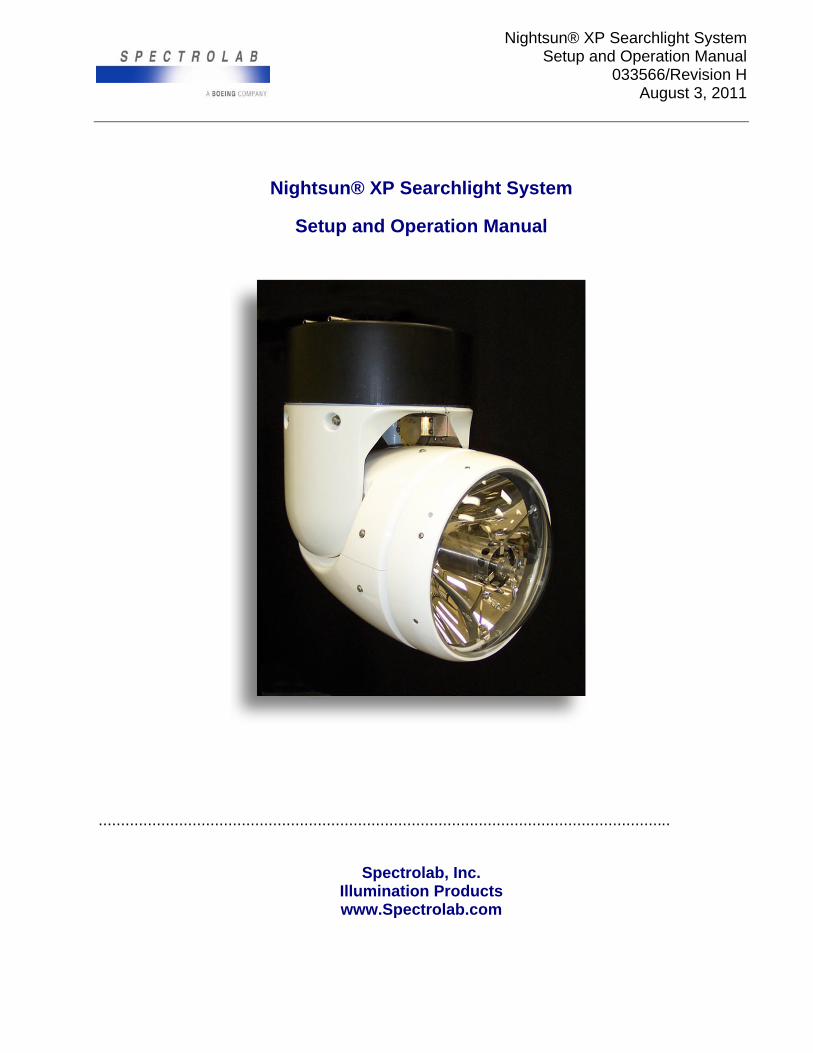
Nightsun® XP Searchlight System Setup and Operation Manual
033566/Revision H August 3, 2011
Nightsun® XP Searchlight System
Setup and Operation Manual
................................................................................................................................
Spectrolab, Inc. Illumination Products www.Spectrolab.com
Nightsun® XP Searchlight System Setup and Operation Manual
033566/Revision H August 3, 2011
CHANGE RECORD
REV AUTHORIZATION CHANGE DESCRIPTION APPROVAL
NC S. Vargas Initial Release F. Sanchez 1/27/06 A S. Vargas Per ECO F. Sanchez 9/13/06 B G.P. Estrada Per ECO F. Sanchez 11/10/06 C G.P. Estrada Per ECO F. Sanchez 12/5/07 D G.P. Estrada Per ECO F. Sanchez 9/24/09 E G.P. Estrada Per ECO F. Sanchez 10/02/2009 F G.P. Estrada Per ECO F. Sanchez 6/14/10 G G.P. Estrada Per ECO F. Sánchez 5/19/11 H G.P. Estrada Per ECO F. Sanchez 8/24/11

Nightsun® XP Searchlight System Setup and Operation Manual
033566/Revision H August 3, 2011
i
© 2011 Spectrolab, Inc. All rights reserved.
This document contains material (including proprietary information) protected by copyright. No part of this document may be reproduced or transmitted in any form, by any means, or for any purpose without the express written consent of Spectrolab. Users of this document agree not to manufacture, produce, sell, or lease any product copied from or based on the information contained in this document without prior written consent from Spectrolab. Unauthorized reproduction or distribution of copyrighted material in the United States is subject to civil and criminal remedies pursuant to Title 17 of the United States Code.
Nightsun® is a registered trademark of Spectrolab, Inc.
Spectrolab, Inc. 12500 Gladstone Avenue Sylmar, CA 91342 USA 818-365-4611 www.Spectrolab.com
Document #033566. Printed in the United States of America
Nightsun® XP Searchlight System Setup and Operation Manual
033566/Revision H August 3, 2011
ii
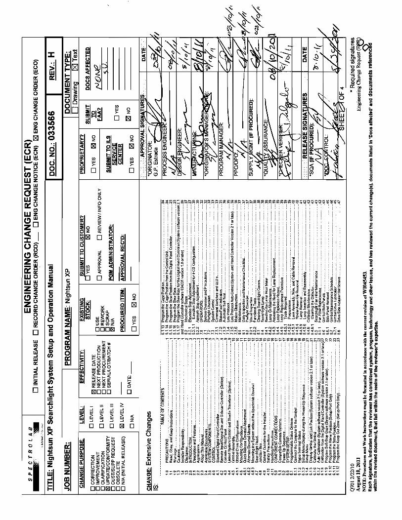
TABLE OF CONTENTS 1.0 PRECAUTIONS ........................................................................................................ 1 1.1 Read, Obey, and Keep Instructions .......................................................................... 1 1.2 Warnings ................................................................................................................... 1 1.3 Cautions .................................................................................................................... 1 1.4 Installer Responsibility .............................................................................................. 1 1.5 Disclaimer ................................................................................................................. 2 2.0 INTRODUCTION ....................................................................................................... 3 2.1 Description and Features .......................................................................................... 3 2.2 Applications ............................................................................................................... 3 2.3 About This Manual .................................................................................................... 3 2.4 Applicable Documents .............................................................................................. 4 3.0 SYSTEM COMPONENTS ......................................................................................... 5 4.0 CONTROL ................................................................................................................. 7 4.1 Standard Digital Hand Controller ............................................................................... 7 4.2 Remote Input/Output Box and Sidecar Controller (Option) ....................................... 8 4.3 Console Control Panel .............................................................................................. 9 4.4 Linked System Control and Shadin Translator (Option) ............................................ 9 4.5 Gimbal Assembly .................................................................................................... 10 4.5.1 Gimbal Drive Configurations ................................................................................... 10 4.6 Mounting Configurations ......................................................................................... 11 4.6.1 Quick-Release Dovetail Attachment ........................................................................ 11 4.6.2 Alternate Dovetail Mounts ....................................................................................... 12 4.6.3 Mounting the System without the Spectrolab Dovetail ............................................ 12 4.7 Searchlight Head ..................................................................................................... 13 4.8 Junction Box ............................................................................................................ 14 4.9 General Guideline for the Installer ........................................................................... 15 4.10 Safety Precautions .................................................................................................. 15 4.11 Handling Precautions .............................................................................................. 16 5.0 COMPONENT CONNECTIONS ............................................................................. 17 5.1 Compatible Camera Systems .................................................................................. 17 5.2 Power Up Sequence ............................................................................................... 17 6.0 SYSTEM SETUP .................................................................................................... 18 6.1 Programmable Setup Options ................................................................................. 18 6.1.1 Connect the Computer to the Gimbal ...................................................................... 18 6.1.2 HyperTerminal Setup .............................................................................................. 18 6.1.3 Setup Menu Display during the Power-Up Sequence ............................................. 19 6.1.4 Setup Menu ............................................................................................................. 21 6.1.5 Display Gimbal and Link Position (System software version 2.1 or later) ............... 21 6.1.6 Calibrate the Gimbal ............................................................................................... 21 6.1.7 Auto Calibration (System software version 2.1 or later) .......................................... 22 6.1.8 Calibration from the Digital Hand Controller (System software version 2.1 or later) 22 6.1.9 Program Soft-Stop Gaps (System software version 2.1 or later) ............................. 22 6.1.10 Program the Home Position (Setup Port Only) ........................................................ 22 6.1.11 Program the Stow Position ...................................................................................... 23 6.1.12 Program the Keep Out Zone (Setup Port Only) ....................................................... 23
Nightsun® XP Searchlight System Setup and Operation Manual
033566/Revision H August 3, 2011
iii
6.1.13 Program the Cage Position ..................................................................................... 24 6.1.14 Program the Cage Position from the Control Unit ................................................... 24 6.1.15 Program the Stow Position from the Digital Hand Controller ................................... 25 6.1.16 Program the Slew Rate ........................................................................................... 25 6.1.17 Program the Slew Rate for the Digital Hand Controller (System software version 2.1 and Hand Controller software 034231 version 1.0 or later) .................................................. 26 6.2 Mechanical Stops .................................................................................................... 27 6.2.1 Elevation Stop Adjustment ...................................................................................... 27 6.2.1.1 Elevation Stop Adjustment for IFCO Configuration .............................................. 30 6.2.2 Azimuth Stop Adjustment ........................................................................................ 30 7.0 OPERATIONS ......................................................................................................... 32 7.1 System Overview and Precautions ......................................................................... 32 7.2 Preflight Checklist ................................................................................................... 32 7.3 System Control ........................................................................................................ 33 7.3.1 Command Switches and LED’s ............................................................................... 33 7.3.2 Status/Fault indicators ............................................................................................. 35 7.3.3 Automatic Self-Test ................................................................................................. 36 7.3.4 Link Protocol ........................................................................................................... 36 7.3.5 Link Protocol Auto-Detect (System and Hand Controller Version 2.1 or later) ........ 36 7.3.6 Motion Obstruction .................................................................................................. 36 8.0 Maintenance ............................................................................................................ 37 8.1 Daily Inspection and Maintenance Checklist ........................................................... 37 8.2 Preflight Checklist ................................................................................................... 37 8.2.1 Visual Inspection ..................................................................................................... 37 8.2.2 Functional Tests ...................................................................................................... 38 8.3 Cleaning Searchlight Covers ................................................................................... 38 8.4 Searchlight Lamp .................................................................................................... 38 8.4.1 Reading the Lamp Hour Meter ................................................................................ 38 8.4.2 Lamp On Maintenance ............................................................................................ 39 8.4.3 Assessing the Need for Lamp Replacement ........................................................... 39 8.4.4 Lamp Explosion Hazard .......................................................................................... 39 8.4.5 Lamp Replacement Procedure ................................................................................ 39 8.4.5.1 Tools Required .................................................................................................... 39 8.4.5.2 Preparations ........................................................................................................ 39 8.4.5.3 Lens Assembly, Wire, and Cable Removal .......................................................... 40 8.4.5.4 Spider Assembly Removal ................................................................................... 40 8.4.5.5 Lamp Removal ..................................................................................................... 41 8.4.5.6 Lamp Insertion and Reassembly ......................................................................... 42 8.4.6 Collector Maintenance ............................................................................................ 43 8.4.6.1 Cleaning the Collector .......................................................................................... 43 8.5 Searchlight Fan Filter Maintenance ......................................................................... 43 8.5.1 Fan Filter Replacement ........................................................................................... 43 8.6 Gimbal Side Panels ................................................................................................. 45 8.6.1 Side Panel Removal ................................................................................................ 46 8.7 Gimbal Maintenance Schedule ............................................................................... 46 8.7.1 Gimbal Drive Lubrication ......................................................................................... 46 8.8 Drive Side Adapter Set Screws ............................................................................... 47
Nightsun® XP Searchlight System Setup and Operation Manual
033566/Revision H August 3, 2011
iv
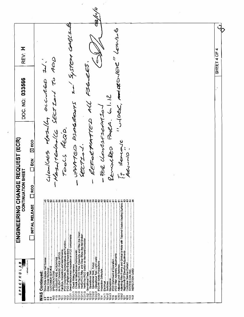
8.9 Inner Cover Removal .............................................................................................. 48 9.0 CUSTOMER SERVICE ........................................................................................... 49 10.0 SPECIFICATIONS .................................................................................................. 50 11.0 GLOSSARY AND ACRONYMS .............................................................................. 53 12.0 IN FLIGHT CHANGE OVER (IFCO) ....................................................................... 55 12.1 Function, Inspection and Maintenance .................................................................... 55 12.2 IFCO Description, Nomenclature and Function ....................................................... 55 12.3 IFCO Preflight and/or Daily Inspections .................................................................. 56 12.3.1 Overall Mechanical Inspection of IFCO components: ............................................. 57 12.3.1.1 Check Wiring Harness ......................................................................................... 57 12.3.1.2 Check All Mechanical Components: .................................................................... 57 12.3.1.3 Verify the IFCO Filter Assembly and Filter Are Clean .......................................... 57 12.3.1.4 Verify IFCO Filter and Clear Glass Are Not Broken ............................................. 57 12.3.1.5 Verify the IFCO Switch on the Hand Controller .................................................... 57 12.3.2 Operational Tests .................................................................................................... 57 12.3.2.1 Operational Test .................................................................................................. 57 12.3.2.2 Operational Test, Focus ....................................................................................... 58 12.3.2.3 Operational Test, Light Leaks .............................................................................. 59 12.3.3 IFCO/IR Safety Precautions .................................................................................... 59 12.4 Inspection Schedule ................................................................................................ 59 12.4.1 Electrical.................................................................................................................. 59 12.4.2 Switches .................................................................................................................. 59 12.4.3 Mechanical .............................................................................................................. 60 12.5 IFCO Statement of Operation .................................................................................. 60 12.6 IFCO Filter Assembly Adjustments ......................................................................... 60 12.6.1 Adjusting Limit Switches ......................................................................................... 60 12.6.2 Adjusting Filter Frame and Gimbal to Mate with Tapered Gasket Sealing Surface . 60 12.7 Nightsun® XP Elevation Adjustments ..................................................................... 62 12.8 Customer Service Contact ...................................................................................... 62 13.0 SYSTEM CABLING ................................................................................................. 63 13.1 Standard System ..................................................................................................... 63 13.2 IFCO System ........................................................................................................... 64 14.0 INSPECTION CARD ............................................................................................... 65
Nightsun® XP Searchlight System Setup and Operation Manual
033566/Revision H August 3, 2011
v
LIST OF FIGURES Figure 1 Standard Hand Controller ........................................................................................ 7 Figure 2 Hand Controller Faceplate ...................................................................................... 8 Figure 3 Remote I/O Box ........................................................................................................ 8 Figure 4 Sidecar Controller ................................................................................................... 8 Figure 5 Console Mount Control Panel ................................................................................. 9 Figure 7 Direct Drive Configuration ...................................................................................... 10 Figure 9 Top View of Gimbal Assembly with Spectrolab Dovetail Attachment .................... 11 Figure 10 Paravion Dovetail Mount ..................................................................................... 12 Figure 12 Top and Side View of Gimbal Shroud ................................................................. 13 Figure 13 Searchlight Head ................................................................................................. 13 Figure 14 Junction Box ........................................................................................................ 14 Figure 15 Lift Handle Locations ........................................................................................... 16 Figure 16 System Connections ........................................................................................... 17 Figure 17 Terminal Connection ........................................................................................... 18 Figure 18 COM Port Selection ............................................................................................. 19 Figure 19 COM Settings ...................................................................................................... 19 Figure 20 HyperTerminal Settings ....................................................................................... 19 Figure 21 Setup Menu ......................................................................................................... 20 Figure 22 Menu Options ...................................................................................................... 20 Figure 23 Calibration Activation .......................................................................................... 22 Figure 24 Program Cage ..................................................................................................... 24 Figure 25 Program Stow ..................................................................................................... 25 Figure 26 Program Slew Rate ............................................................................................. 26 Figure 27 Gimbal Elevation Mechanical Stops .................................................................... 27 Figure 28 Maximum Lookdown Angle ................................................................................. 28 Figure 29 Maximum Lookup Angle ...................................................................................... 28 Figure 30 Detailed View of Adjustable Stop Blocks ............................................................. 29 Figure 31 Elevation Stop Adjustment for IFCO Configuration .............................................. 30 Figure 32 Inner Cover Access Door .................................................................................... 30 Figure 33 Bottom View of Gimbal showing Stop Block Pin and One Adjustable Stop Pin Installed ................................................................................................................................ 31 Figure 34 Location of Lamp Hour Meter .............................................................................. 38 Figure 35 Lens Assembly, Searchlight Housing, and Spider Assembly ............................... 40 Figure 36 Spider Assembly Removal ................................................................................... 41 Figure 37 Removing the Lamp ............................................................................................ 42 Figure 38 Fan Filter Replacement ........................................................................................ 44 Figure 39 Gimbal Assembly Left Side Panel ....................................................................... 45 Figure 40 Rear View of Gimbal Showing Side Panels......................................................... 46 Figure 41 Gimbal Showing Chain Drive Mechanism ............................................................ 47 Figure 42 Gimbal Set Screws .............................................................................................. 47 Figure 43 Gimbal Assembly Showing Inner Cover .............................................................. 48 Figure 44 Gimbal Inner Cover ............................................................................................. 48 Figure 45 IFCO Filter in the Closed Position ....................................................................... 55 Figure 46 IFCO Activation ................................................................................................... 56 Figure 47 IFCO Contact Plate ............................................................................................. 61
Nightsun® XP Searchlight System Setup and Operation Manual
033566/Revision H August 3, 2011
1
1.0 PRECAUTIONS
1.1 Read, Obey, and Keep Instructions
To ensure the safety of personnel and equipment when operating the Nightsun® XP Searchlight System, it is important to read and obey all warnings, cautions, and instructions in this document and on the equipment. Keep this document for reference.
1.2 Warnings
Use and Placement The Nightsun® XP is designed and manufactured to provide years of safe operation. Improper use or placement of the system, however, can result in electrical shock or fire hazards. The safeguards incorporated into the system will help protect you if you observe all warnings, cautions, and procedures for installation, operation, maintenance, and service.
Shock To avoid electrocution or shock to personnel do not operate the Nightsun® XP without the covers for the Gimbal or Searchlight installed. Removal of these covers can expose personnel to dangerous voltage levels.
Gimbal Motion When the Gimbal rotates, the Gimbal motors develop forces that can injure personnel. Keep a safe distance from the Gimbal to avoid possible injury.
Loose Clothing The Gimbal has moving parts that can trap loose clothing and cause personal injury. To avoid injuries, keep loose-fitting clothing and personnel away from the equipment during operation.
System Startup Motion When the Nightsun® XP is powered up, it automatically follows a series of initialization motions. To avoid injury, make sure that all personnel are beyond the system’s range of motion before beginning the power-up cycle.
1.3 Cautions
Unauthorized Repair or Maintenance The Nightsun® XP contains parts that a user can maintain and repair. Authorized repair or maintenance stations may be required at a customer facility, and failure to comply may cause the warranty (or any remaining portion of it) to be void. Maintenance may be performed by an authorized facility by following instructions in the Maintenance and Troubleshooting Guide (033566-1). If there are any questions about what is and what is not repairable, please contact Spectrolab Customer Service at 800-936-4888.
Locking Features Required Because the Nightsun® XP is subject to vibration in its normal operating environment, the hardware used for system attachment requires positive locking features such as locknuts, lock wire, etc.
Electrostatic Sensitive Devices The Nightsun® XP has electrostatic sensitive devices (ESD). Observe precautions for handling ESDs.
1.4 Installer Responsibility
It is the responsibility of Nightsun® XP installers to ensure the integrity and safety of the installation, configuration, and integration with the aircraft or other operational platform.
Nightsun® XP Searchlight System Setup and Operation Manual
033566/Revision H August 3, 2011
2
1.5 Disclaimer
The information in this document is current as of the publication date. The manufacturer reserves the right to make changes to this document and products associated at any time without notice.
Nightsun® XP Searchlight System Setup and Operation Manual
033566/Revision H August 3, 2011
3
2.0 INTRODUCTION
2.1 Description and Features
The Nightsun® XP is a versatile, mobile, high-intensity light source that makes it possible to illuminate an area from a safe distance or altitude. It is a complete system and is equipped with all of the electrical components, software, and hardware connections necessary to operate and control its range of motion.
The Searchlight uses an air-cooled, high-intensity xenon arc lamp that emits light that is the same color as daylight. It starts rapidly, and it can be operated continuously or started and stopped to meet operational requirements.
The Gimbal assembly that supports the Searchlight enables users to aim the Searchlight beam at various positions with respect to azimuth (horizontal directions) and elevation (vertical directions).
The Nightsun® XP is easy to operate and responds to rate (directional) commands from a Hand Controller. The Hand Controller uses a high-speed digital communication link to transmit commands to a central processing unit (CPU) located in the Gimbal. It also receives system status information from the CPU.
The Nightsun® XP can be linked to the directional controllers of other devices. This enables synchronized positioning between these devices and the Nightsun® XP. It also supports additional options and connections.
2.2 Applications
While the Nightsun® XP can be installed on a variety of mobile platforms, it is particularly useful for nighttime aerial reconnaissance when installed on helicopters and fixed-wing aircraft. Applications include military, law enforcement, search and rescue; assessment of emergency-landing areas; surveillance of power lines, critical installations, borders, and coastlines; and nighttime photography using color film designed for daytime use. The Nightsun® XP also is useful for applications that are not described in this manual. Please contact Spectrolab Customer Service to ask about your specific requirements.
2.3 About This Manual
This manual provides the following information:
Information to help you to set up and connect the Nightsun® XP components
Information to help you operate the Nightsun® XP
Information to help you maintain certain aspects of the Nightsun® XP and obtain service
Nightsun® XP Searchlight System Setup and Operation Manual
033566/Revision H August 3, 2011
4
2.4 Applicable Documents
033728, INSTALLATION CONSIDERATIONS - SOURCE DATA, STANDARD SYSTEM 033838, INSTALLATION CONSIDERATIONS - SOURCE DATA, IFCO SYSTEM 032507, LINK INTERFACE CONTROL DOCUMENT 032738, HAND CONTROLLER OUTLINE AND MOUNTING 032787-OEM, REMOTE I/O OUTLINE AND MOUNTING 033002-OEM, SIDECAR OUTLINE AND MOUNTING 033401-OEM, XP INTERCONNECT DIAGRAM 033405-OEM, SEARCHLIGHT AND GIMBAL OUTLINE AND MOUNTING (ENVELOPE) 033507-OEM, SYSTEM INTERFACE DIAGRAM 033287, NIGHTSUN XP SYSTEM SOFTWARE 034261, REMOTE I/O BOX SOFTWARE 034231, HAND CONTROLLER GEN. 2 SOFTWARE PL034350, NIGHTSUN® XP SETUP KIT 034363, NIGHTSUN® XP CONSOLE CONTROL PANEL 034438, NIGHTSUN® XP CONSOLE CONTROL PANEL SOFTWARE
Nightsun® XP Searchlight System Setup and Operation Manual
033566/Revision H August 3, 2011
5
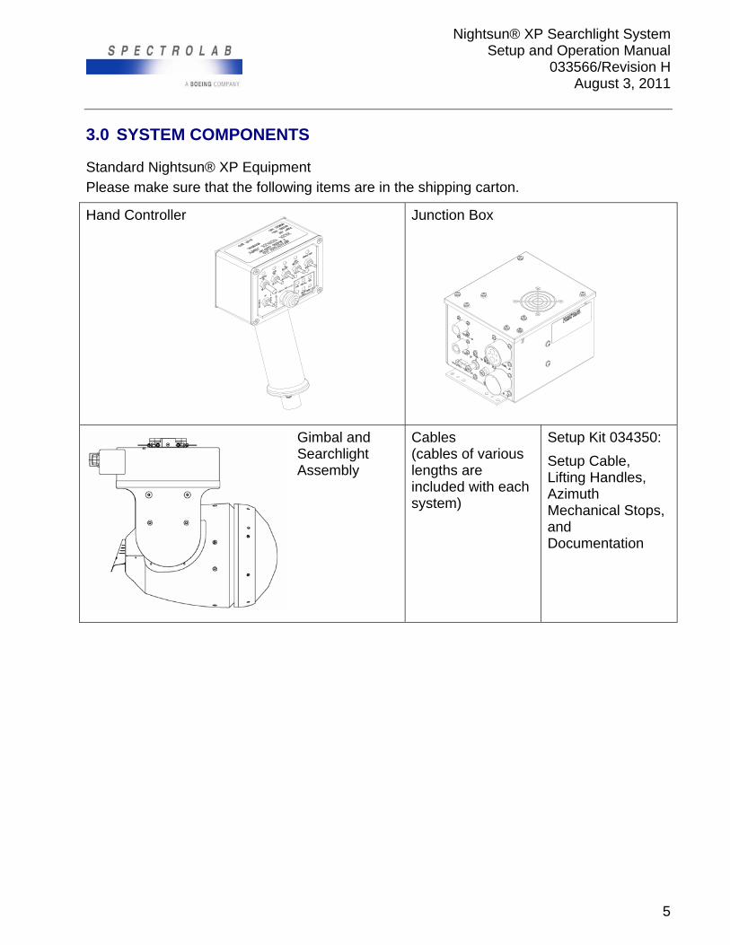
3.0 SYSTEM COMPONENTS
Standard Nightsun® XP Equipment
Please make sure that the following items are in the shipping carton.
Hand Controller
Junction Box
Gimbal and Searchlight Assembly
Cables (cables of various lengths are included with each system)
Setup Kit 034350:
Setup Cable, Lifting Handles, Azimuth Mechanical Stops, and Documentation
Nightsun® XP Searchlight System Setup and Operation Manual
033566/Revision H August 3, 2011
6
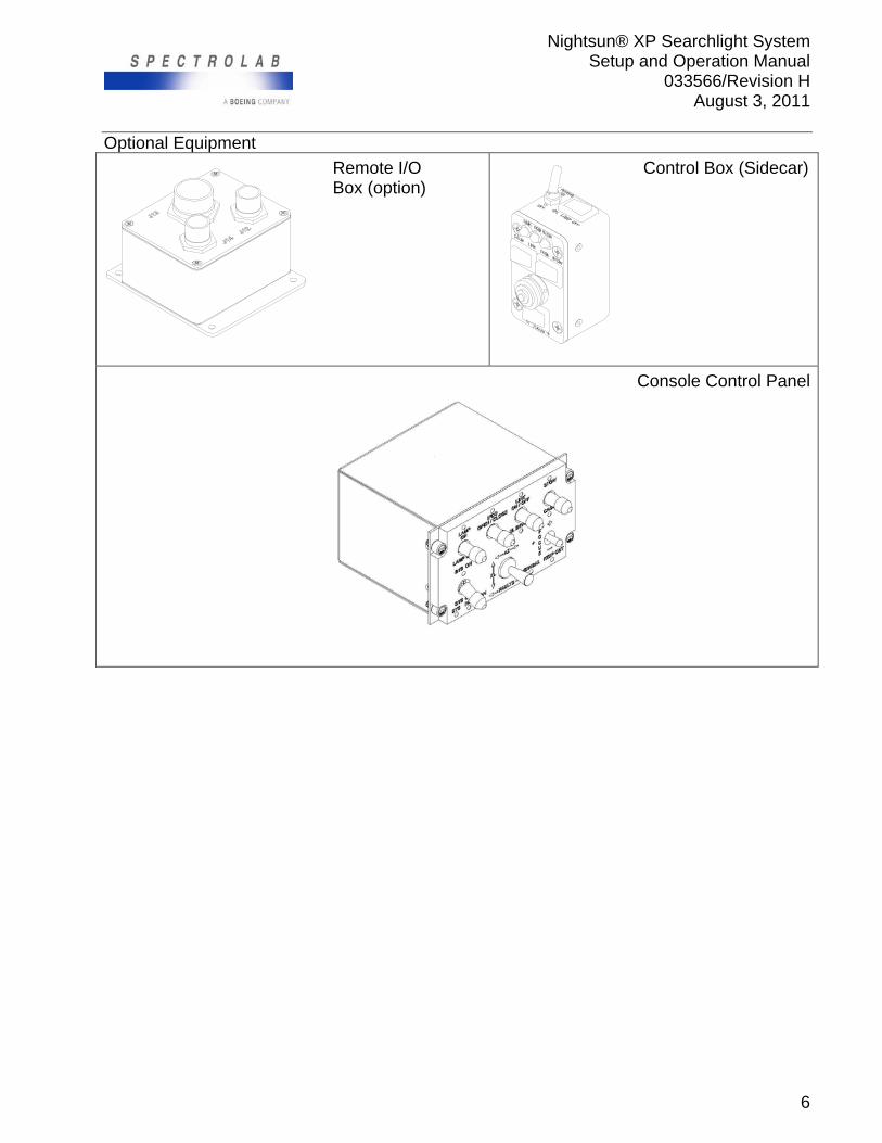
Optional Equipment
Remote I/O Box (option)
Control Box (Sidecar)
Console Control Panel
Nightsun® XP Searchlight System Setup and Operation Manual
033566/Revision H August 3, 2011
7
4.0 CONTROL
4.1 Standard Digital Hand Controller
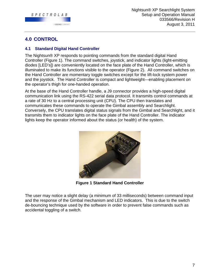
The Nightsun® XP responds to pointing commands from the standard digital Hand Controller (Figure 1). The command switches, joystick, and indicator lights (light-emitting diodes [LED’s]) are conveniently located on the face plate of the Hand Controller, which is illuminated to make its functions visible to the operator (Figure 2). All command switches on the Hand Controller are momentary toggle switches except for the lift-lock system power and the joystick. The Hand Controller is compact and lightweight—enabling placement on the operator’s thigh for one-handed operation.
At the base of the Hand Controller handle, a J9 connector provides a high-speed digital communication link using the RS-422 serial data protocol. It transmits control commands at a rate of 30 Hz to a central processing unit (CPU). The CPU then translates and communicates these commands to operate the Gimbal assembly and Searchlight. Conversely, the CPU translates digital status signals from the Gimbal and Searchlight, and it transmits them to indicator lights on the face plate of the Hand Controller. The indicator lights keep the operator informed about the status (or health) of the system.
Figure 1 Standard Hand Controller
The user may notice a slight delay (a minimum of 33 milliseconds) between command input and the response of the Gimbal mechanism and LED indicators. This is due to the switch de-bouncing technique used by the software in order to prevent false commands such as accidental toggling of a switch.
Nightsun® XP Searchlight System Setup and Operation Manual
033566/Revision H August 3, 2011
8
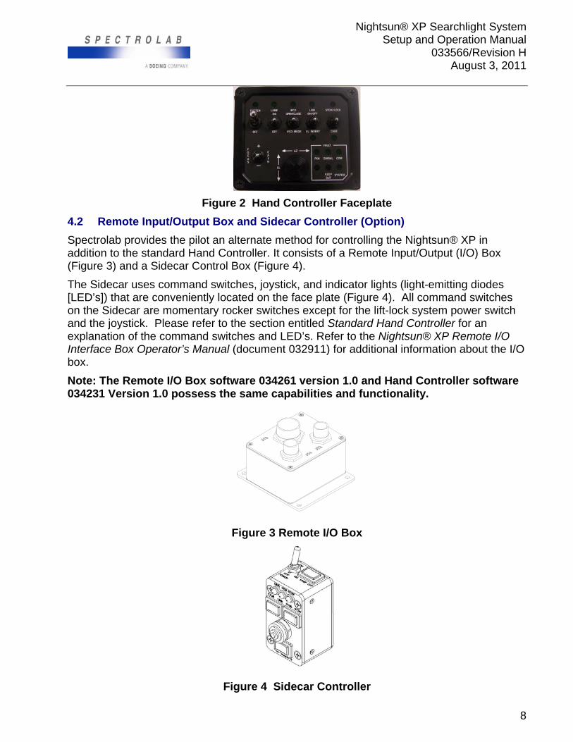
Figure 2 Hand Controller Faceplate
4.2 Remote Input/Output Box and Sidecar Controller (Option)
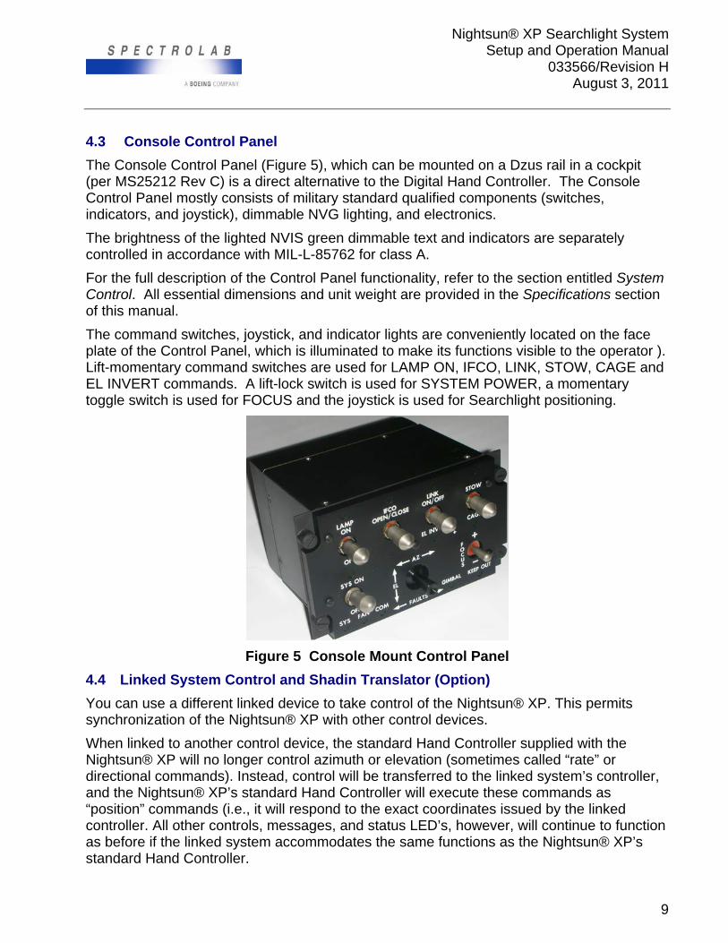
Spectrolab provides the pilot an alternate method for controlling the Nightsun® XP in addition to the standard Hand Controller. It consists of a Remote Input/Output (I/O) Box (Figure 3) and a Sidecar Control Box (Figure 4).
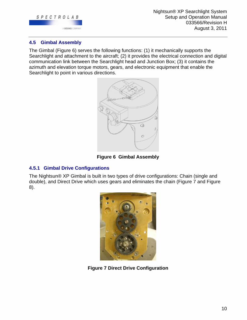
The Sidecar uses command switches, joystick, and indicator lights (light-emitting diodes [LED’s]) that are conveniently located on the face plate (Figure 4). All command switches on the Sidecar are momentary rocker switches except for the lift-lock system power switch and the joystick. Please refer to the section entitled Standard Hand Controller for an explanation of the command switches and LED’s. Refer to the Nightsun® XP Remote I/O Interface Box Operator’s Manual (document 032911) for additional information about the I/O box.
Note: The Remote I/O Box software 034261 version 1.0 and Hand Controller software 034231 Version 1.0 possess the same capabilities and functionality.
Figure 3 Remote I/O Box
Figure 4 Sidecar Controller
Nightsun® XP Searchlight System Setup and Operation Manual
033566/Revision H August 3, 2011
9
4.3 Console Control Panel
The Console Control Panel (Figure 5), which can be mounted on a Dzus rail in a cockpit (per MS25212 Rev C) is a direct alternative to the Digital Hand Controller. The Console Control Panel mostly consists of military standard qualified components (switches, indicators, and joystick), dimmable NVG lighting, and electronics.
The brightness of the lighted NVIS green dimmable text and indicators are separately controlled in accordance with MIL-L-85762 for class A.
For the full description of the Control Panel functionality, refer to the section entitled System Control. All essential dimensions and unit weight are provided in the Specifications section of this manual.
The command switches, joystick, and indicator lights are conveniently located on the face plate of the Control Panel, which is illuminated to make its functions visible to the operator ). Lift-momentary command switches are used for LAMP ON, IFCO, LINK, STOW, CAGE and EL INVERT commands. A lift-lock switch is used for SYSTEM POWER, a momentary toggle switch is used for FOCUS and the joystick is used for Searchlight positioning.
Figure 5 Console Mount Control Panel
4.4 Linked System Control and Shadin Translator (Option)
You can use a different linked device to take control of the Nightsun® XP. This permits synchronization of the Nightsun® XP with other control devices.
When linked to another control device, the standard Hand Controller supplied with the Nightsun® XP will no longer control azimuth or elevation (sometimes called “rate” or directional commands). Instead, control will be transferred to the linked system’s controller, and the Nightsun® XP’s standard Hand Controller will execute these commands as “position” commands (i.e., it will respond to the exact coordinates issued by the linked controller. All other controls, messages, and status LED’s, however, will continue to function as before if the linked system accommodates the same functions as the Nightsun® XP’s standard Hand Controller.
Nightsun® XP Searchlight System Setup and Operation Manual
033566/Revision H August 3, 2011
10
4.5 Gimbal Assembly
The Gimbal (Figure 6) serves the following functions: (1) it mechanically supports the Searchlight and attachment to the aircraft; (2) it provides the electrical connection and digital communication link between the Searchlight head and Junction Box; (3) it contains the azimuth and elevation torque motors, gears, and electronic equipment that enable the Searchlight to point in various directions.
Figure 6 Gimbal Assembly
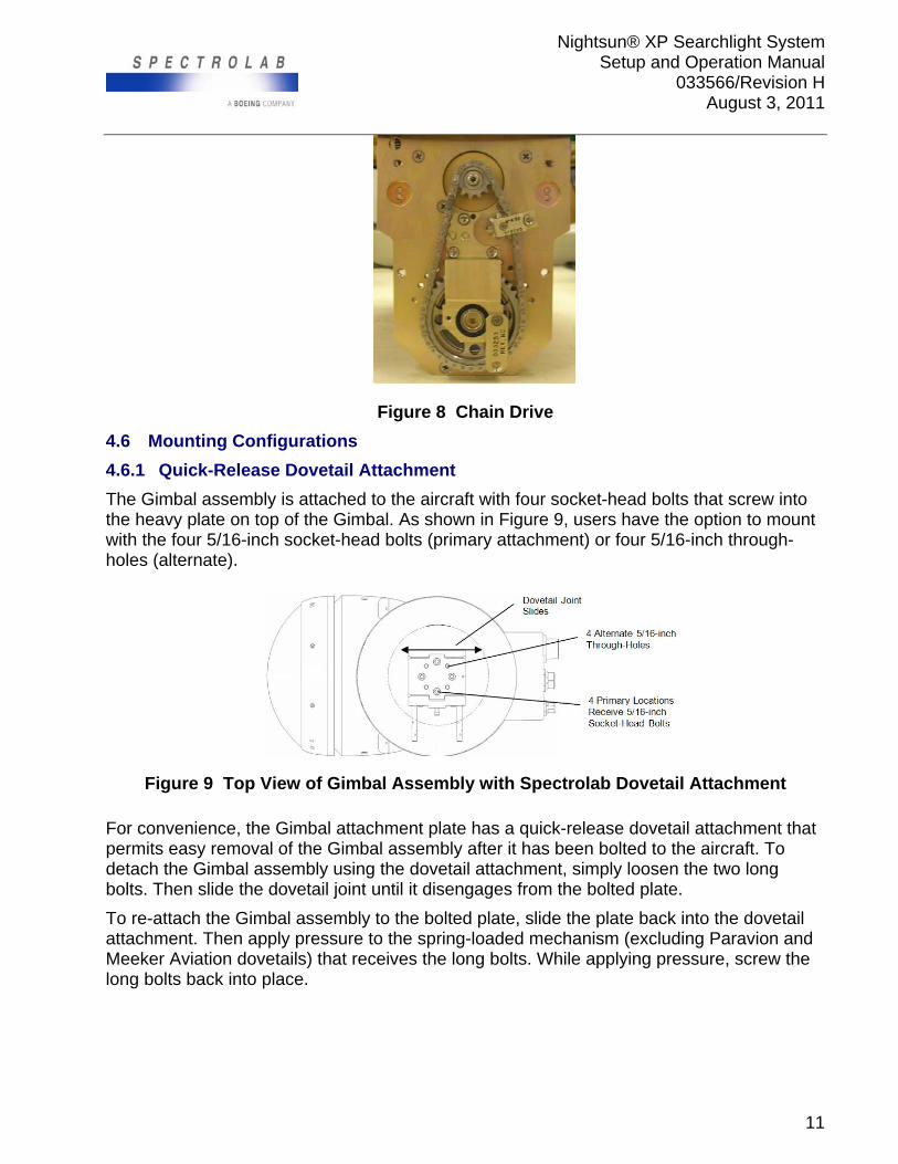
4.5.1 Gimbal Drive Configurations
The Nightsun® XP Gimbal is built in two types of drive configurations: Chain (single and double), and Direct Drive which uses gears and eliminates the chain (Figure 7 and Figure 8).
Figure 7 Direct Drive Configuration
Nightsun® XP Searchlight System Setup and Operation Manual
033566/Revision H August 3, 2011
11
Figure 8 Chain Drive
4.6 Mounting Configurations
4.6.1 Quick-Release Dovetail Attachment
The Gimbal assembly is attached to the aircraft with four socket-head bolts that screw into the heavy plate on top of the Gimbal. As shown in Figure 9, users have the option to mount with the four 5/16-inch socket-head bolts (primary attachment) or four 5/16-inch through-holes (alternate).
Figure 9 Top View of Gimbal Assembly with Spectrolab Dovetail Attachment
For convenience, the Gimbal attachment plate has a quick-release dovetail attachment that permits easy removal of the Gimbal assembly after it has been bolted to the aircraft. To detach the Gimbal assembly using the dovetail attachment, simply loosen the two long bolts. Then slide the dovetail joint until it disengages from the bolted plate.
To re-attach the Gimbal assembly to the bolted plate, slide the plate back into the dovetail attachment. Then apply pressure to the spring-loaded mechanism (excluding Paravion and Meeker Aviation dovetails) that receives the long bolts. While applying pressure, screw the long bolts back into place.
Nightsun® XP Searchlight System Setup and Operation Manual
033566/Revision H August 3, 2011
12
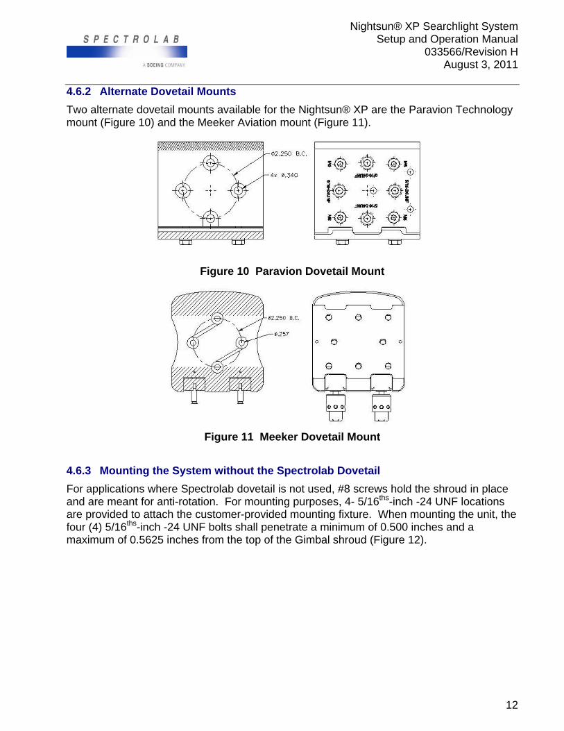
4.6.2 Alternate Dovetail Mounts
Two alternate dovetail mounts available for the Nightsun® XP are the Paravion Technology mount (Figure 10) and the Meeker Aviation mount (Figure 11).
Figure 10 Paravion Dovetail Mount
Figure 11 Meeker Dovetail Mount
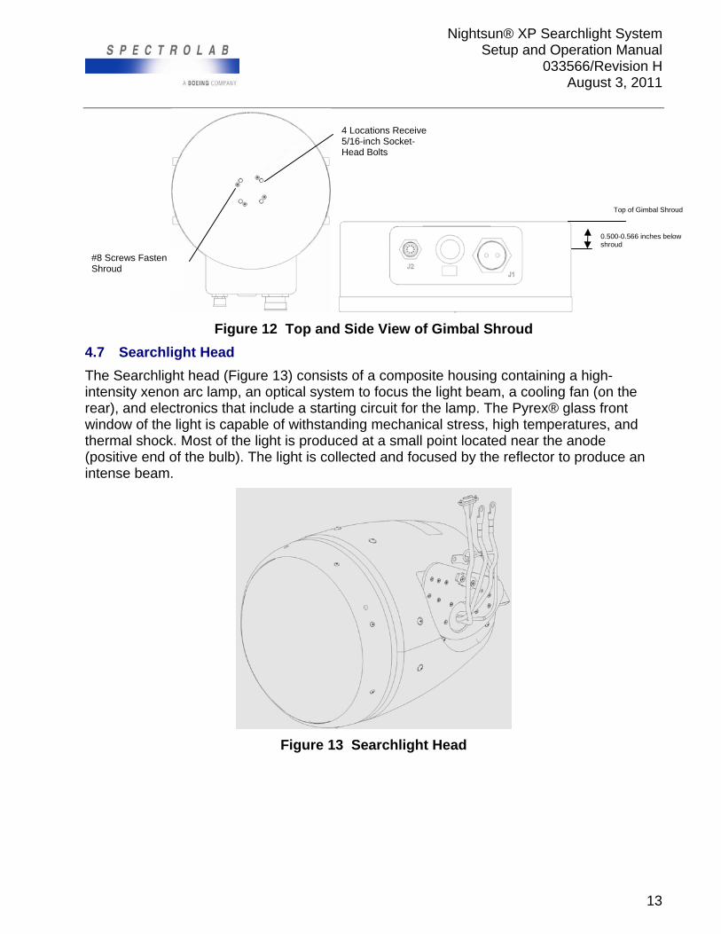
4.6.3 Mounting the System without the Spectrolab Dovetail
For applications where Spectrolab dovetail is not used, #8 screws hold the shroud in place and are meant for anti-rotation. For mounting purposes, 4- 5/16ths-inch -24 UNF locations are provided to attach the customer-provided mounting fixture. When mounting the unit, the four (4) 5/16ths-inch -24 UNF bolts shall penetrate a minimum of 0.500 inches and a maximum of 0.5625 inches from the top of the Gimbal shroud (Figure 12).
Nightsun® XP Searchlight System Setup and Operation Manual
033566/Revision H August 3, 2011
13
Figure 12 Top and Side View of Gimbal Shroud
4.7 Searchlight Head
The Searchlight head (Figure 13) consists of a composite housing containing a high-intensity xenon arc lamp, an optical system to focus the light beam, a cooling fan (on the rear), and electronics that include a starting circuit for the lamp. The Pyrex® glass front window of the light is capable of withstanding mechanical stress, high temperatures, and thermal shock. Most of the light is produced at a small point located near the anode (positive end of the bulb). The light is collected and focused by the reflector to produce an intense beam.
Figure 13 Searchlight Head
0.500-0.566 inches below shroud
4 Locations Receive 5/16-inch Socket-Head Bolts
#8 Screws Fasten Shroud
Top of Gimbal Shroud
Nightsun® XP Searchlight System Setup and Operation Manual
033566/Revision H August 3, 2011
14
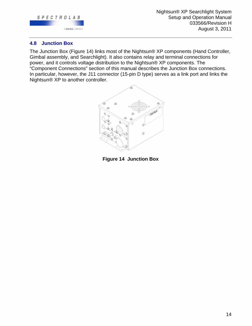
4.8 Junction Box
The Junction Box (Figure 14) links most of the Nightsun® XP components (Hand Controller, Gimbal assembly, and Searchlight). It also contains relay and terminal connections for power, and it controls voltage distribution to the Nightsun® XP components. The “Component Connections” section of this manual describes the Junction Box connections. In particular, however, the J11 connector (15-pin D type) serves as a link port and links the Nightsun® XP to another controller.
Figure 14 Junction Box
Nightsun® XP Searchlight System Setup and Operation Manual
033566/Revision H August 3, 2011
15
4.9 General Guideline for the Installer
Spectrolab does not install the Nightsun® XP. It is the responsibility of system installers to ensure the integrity and safety of the installation, configuration, and integration with the aircraft or other vehicle. When selecting a mounting location, observe the following general guidelines:
This manual should not be your sole guide for specific installations. Assess the safety of your installations on a case-by-case basis.
The Nightsun® XP does not require major airframe modifications because it relies on bulkhead through-connectors for system cabling. Consequently, the Nightsun® XP can be installed on a variety of airborne and non-airborne vehicles. Consult with Spectrolab for assistance in determining your precise installation requirements.
The following technical and safety considerations are important:
- Consider aircraft stress, fatigue, and handling characteristics before you approve an installation design.
- Consider balance and weight distribution with reference to the aircraft’s center of gravity.
- Locate the equipment for favorable aircraft and equipment operation.
- Locate the equipment to facilitate adjustments, maintenance, and repairs.
- Provide optimum mobility for aiming and focusing the light in all flight patterns.
- Route the system cables in ways that minimize their length.
- Consider mounting the Nightsun® XP in a parallel plane with equipment (i.e. camera) to be linked.
- Consider the location of materials that may be affected by heat generated by Searchlight beam.
4.10 Safety Precautions
During operation, the Searchlight’s high-intensity light beam may cause heat damage to exposed surfaces. When installing the Searchlight:
Provide for heat dissipation from the Searchlight beam during operation.
Do not install the Gimbal assembly and Searchlight in locations that allow the light beam to be aimed at nearby temperature-sensitive surfaces without taking proper measures.
Do not expose fuel or other volatile substances to the Searchlight beam.
Prevent the Searchlight from being aimed in ways that adversely affect the in-flight crew.
Install a circuit breaker dedicated to the Nightsun® XP that is accessible to the in-flight crew.
Nightsun® XP Searchlight System Setup and Operation Manual
033566/Revision H August 3, 2011
16
4.11 Handling Precautions
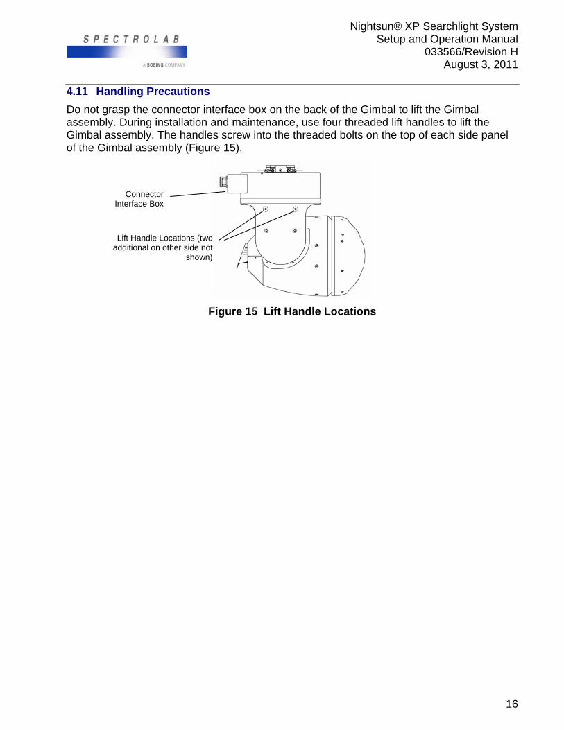
Do not grasp the connector interface box on the back of the Gimbal to lift the Gimbal assembly. During installation and maintenance, use four threaded lift handles to lift the Gimbal assembly. The handles screw into the threaded bolts on the top of each side panel of the Gimbal assembly (Figure 15).
Figure 15 Lift Handle Locations
Lift Handle Locations (two additional on other side not
shown)
Connector Interface Box
Nightsun® XP Searchlight System Setup and Operation Manual
033566/Revision H August 3, 2011
17
5.0 COMPONENT CONNECTIONS
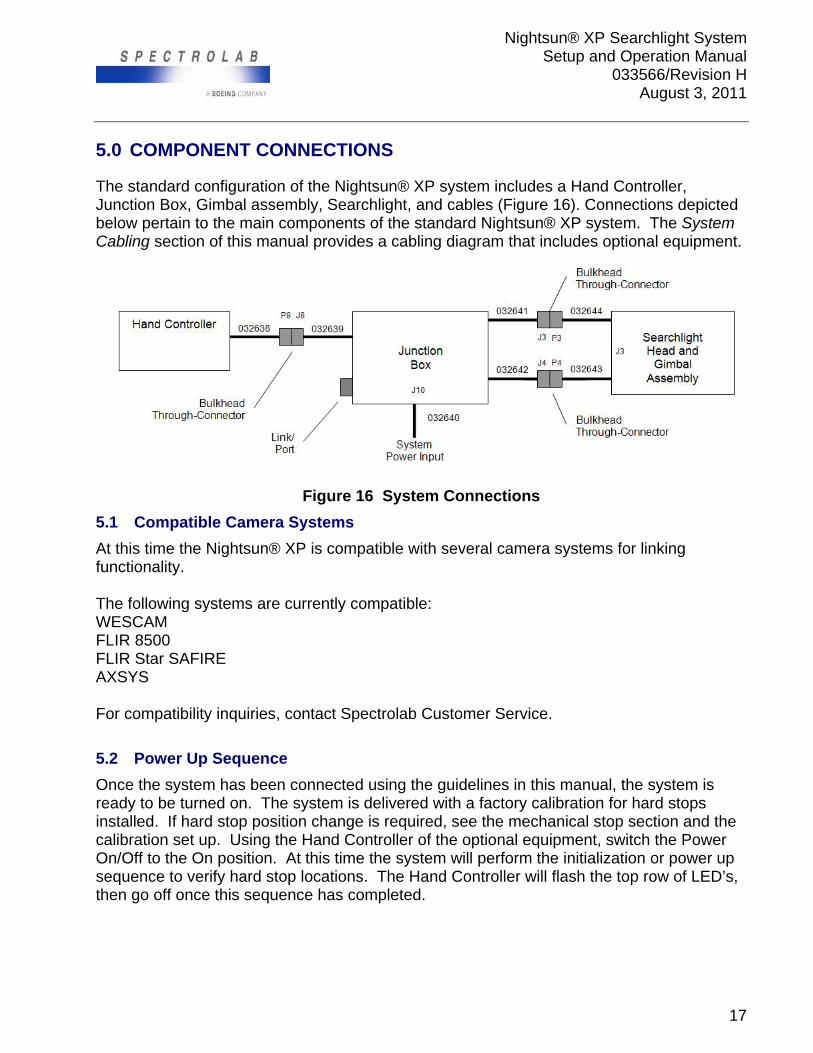
The standard configuration of the Nightsun® XP system includes a Hand Controller, Junction Box, Gimbal assembly, Searchlight, and cables (Figure 16). Connections depicted below pertain to the main components of the standard Nightsun® XP system. The System Cabling section of this manual provides a cabling diagram that includes optional equipment.
Figure 16 System Connections
5.1 Compatible Camera Systems
At this time the Nightsun® XP is compatible with several camera systems for linking functionality. The following systems are currently compatible: WESCAM FLIR 8500 FLIR Star SAFIRE AXSYS For compatibility inquiries, contact Spectrolab Customer Service.
5.2 Power Up Sequence
Once the system has been connected using the guidelines in this manual, the system is ready to be turned on. The system is delivered with a factory calibration for hard stops installed. If hard stop position change is required, see the mechanical stop section and the calibration set up. Using the Hand Controller of the optional equipment, switch the Power On/Off to the On position. At this time the system will perform the initialization or power up sequence to verify hard stop locations. The Hand Controller will flash the top row of LED’s, then go off once this sequence has completed.
Nightsun® XP Searchlight System Setup and Operation Manual
033566/Revision H August 3, 2011
18
6.0 SYSTEM SETUP
6.1 Programmable Setup Options
The Nightsun® XP has great flexibility. For example, users can customize the following programmable settings to meet their particular needs: Keep Out zone, Cage position, stow position, slew rate, and view current settings. To take advantage of these programmable settings, however, it is necessary to (1) establish a computer connection and (2) gain access to a menu of setup options. This section explains these tasks.
6.1.1 Connect the Computer to the Gimbal
Remove the Gimbal right side panel (right side when you directly face the front of a mounted Searchlight) so that you can gain access to the 9-pin setup port. Refer to the sub-section entitled “Side Panel Removal” (in the “Maintenance” section); there are important safety precautions.
Verify system power is off. Once you have removed the right side panel, and the power is off, connect a straight cable to the 9-pin setup port on the Gimbal. Then, turn the system power on and connect the other end of the cable to the standard 9-pin serial port on your computer once the system has completed the power on sequence. If your computer does not have a serial port, you may require a serial-to-USB converter.
Note: To prevent damage to PC and Gimbal hardware, do not ignite lamp with cable connected to setup port or PC. 6.1.2 HyperTerminal Setup
HyperTerminal is a terminal emulator that is part of most PC Windows operating systems, as well as Macintosh computers. If HyperTerminal is not available in your computer, you may download any other available freeware from the internet, such as TeraTerm, Bray’s Terminal, or any other available emulator.
The following instructions are provided to create a HyperTerminal session. Please note that these instructions may not necessarily reflect the steps that you need to take, depending on the operating system on your computer.
1. On your computer, click on Start, All Programs, Accessories, Communications, HyperTerminal.
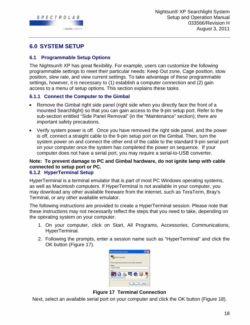
2. Following the prompts, enter a session name such as “HyperTerminal” and click the OK button (Figure 17).
Figure 17 Terminal Connection Next, select an available serial port on your computer and click the OK button (Figure 18).
Nightsun® XP Searchlight System Setup and Operation Manual
033566/Revision H August 3, 2011
19
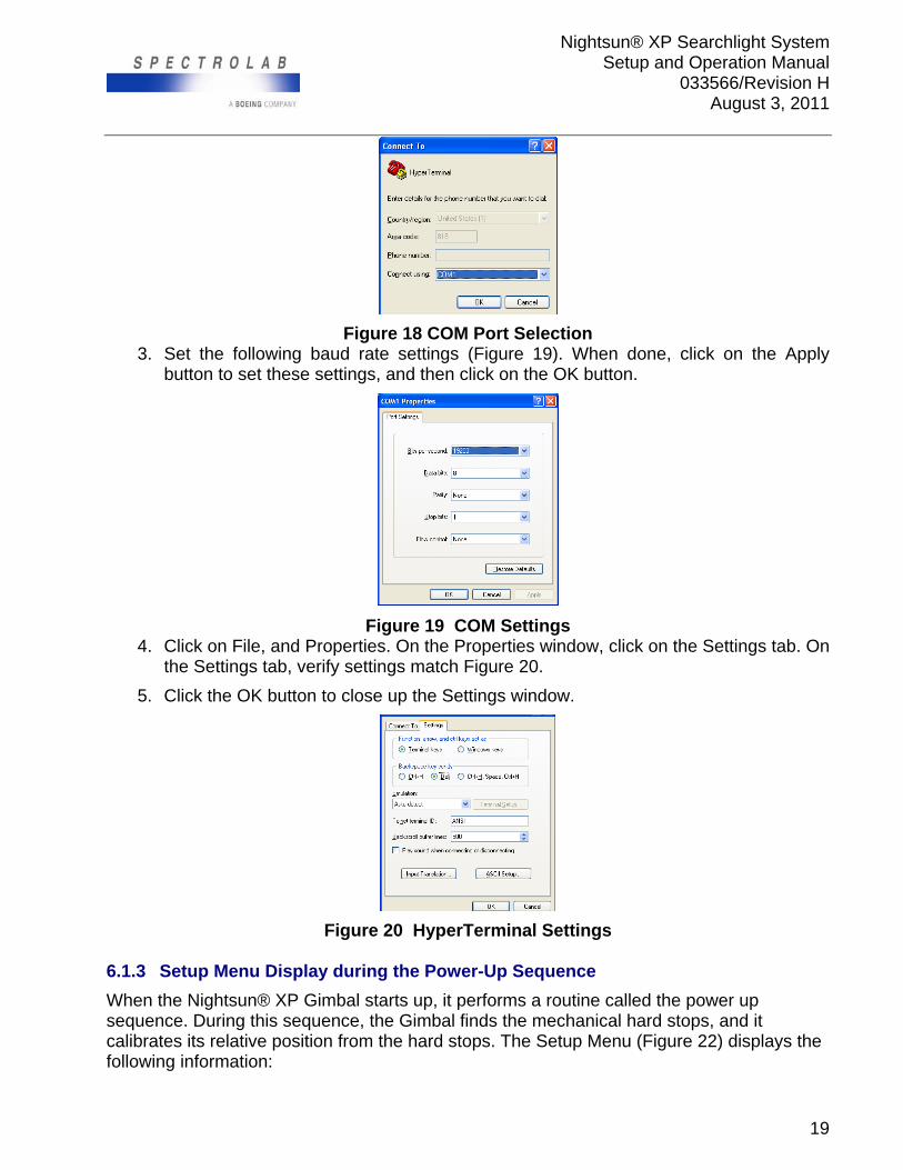
Figure 18 COM Port Selection 3. Set the following baud rate settings (Figure 19). When done, click on the Apply
button to set these settings, and then click on the OK button.
Figure 19 COM Settings 4. Click on File, and Properties. On the Properties window, click on the Settings tab. On
the Settings tab, verify settings match Figure 20.
5. Click the OK button to close up the Settings window.
Figure 20 HyperTerminal Settings
6.1.3 Setup Menu Display during the Power-Up Sequence
When the Nightsun® XP Gimbal starts up, it performs a routine called the power up sequence. During this sequence, the Gimbal finds the mechanical hard stops, and it calibrates its relative position from the hard stops. The Setup Menu (Figure 22) displays the following information:
Nightsun® XP Searchlight System Setup and Operation Manual
033566/Revision H August 3, 2011
20
! Caution
Do not place fingers inside the Gimbal’s area of motion when the power is on.
On the Hand Controller, put the System On switch in the on position to begin the Gimbal initialization process. During this process, the Gimbal automatically goes into the power up sequence by moving to locate hard stops on the elevation and the azimuth.
When the power up sequence is completed, the Nightsun® XP will display the setup menu on the computer screen and prompt instructions. You will now be able to program the system parameters.
Note: The software version may have changed since release of this manual.
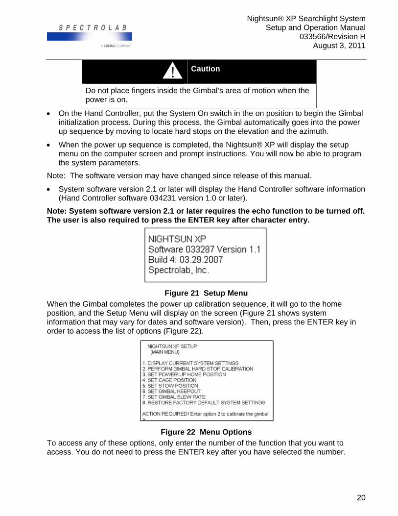
System software version 2.1 or later will display the Hand Controller software information (Hand Controller software 034231 version 1.0 or later).
Note: System software version 2.1 or later requires the echo function to be turned off. The user is also required to press the ENTER key after character entry.
Figure 21 Setup Menu When the Gimbal completes the power up calibration sequence, it will go to the home position, and the Setup Menu will display on the screen (Figure 21 shows system information that may vary for dates and software version). Then, press the ENTER key in order to access the list of options (Figure 22).
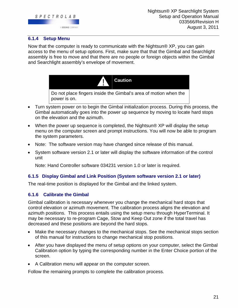
Figure 22 Menu Options To access any of these options, only enter the number of the function that you want to access. You do not need to press the ENTER key after you have selected the number.
Nightsun® XP Searchlight System Setup and Operation Manual
033566/Revision H August 3, 2011
21
6.1.4 Setup Menu
Now that the computer is ready to communicate with the Nightsun® XP, you can gain access to the menu of setup options. First, make sure that that the Gimbal and Searchlight assembly is free to move and that there are no people or foreign objects within the Gimbal and Searchlight assembly’s envelope of movement.
! Caution
Do not place fingers inside the Gimbal’s area of motion when the power is on.
Turn system power on to begin the Gimbal initialization process. During this process, the Gimbal automatically goes into the power up sequence by moving to locate hard stops on the elevation and the azimuth.
When the power up sequence is completed, the Nightsun® XP will display the setup menu on the computer screen and prompt instructions. You will now be able to program the system parameters.
Note: The software version may have changed since release of this manual.
System software version 2.1 or later will display the software information of the control unit
Note: Hand Controller software 034231 version 1.0 or later is required.
6.1.5 Display Gimbal and Link Position (System software version 2.1 or later)
The real-time position is displayed for the Gimbal and the linked system. 6.1.6 Calibrate the Gimbal
Gimbal calibration is necessary whenever you change the mechanical hard stops that control elevation or azimuth movement. The calibration process aligns the elevation and azimuth positions. This process entails using the setup menu through HyperTerminal. It may be necessary to re-program Cage, Stow and Keep Out zone if the total travel has decreased and these positions are beyond the hard stops.
Make the necessary changes to the mechanical stops. See the mechanical stops section of this manual for instructions to change mechanical stop positions.
After you have displayed the menu of setup options on your computer, select the Gimbal Calibration option by typing the corresponding number in the Enter Choice portion of the screen.
A Calibration menu will appear on the computer screen.
Follow the remaining prompts to complete the calibration process.
Nightsun® XP Searchlight System Setup and Operation Manual
033566/Revision H August 3, 2011
22
6.1.7 Auto Calibration (System software version 2.1 or later)
The system will automatically perform a calibration on the first power-up following software installation or when calibration information is detected to be invalid. The auto-calibration eliminates the use of the calibration kit used on previous versions of software. When calibrated, Stow, Home, and Cage positions will be set to 0 (AZ), 0 (EL). 6.1.8 Calibration from the Digital Hand Controller (System software version 2.1 or
later)
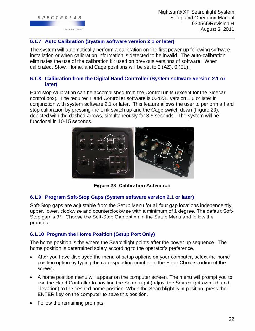
Hard stop calibration can be accomplished from the Control units (except for the Sidecar control box). The required Hand Controller software is 034231 version 1.0 or later in conjunction with system software 2.1 or later. This feature allows the user to perform a hard stop calibration by pressing the Link switch up and the Cage switch down (Figure 23), depicted with the dashed arrows, simultaneously for 3-5 seconds. The system will be functional in 10-15 seconds.
Figure 23 Calibration Activation 6.1.9 Program Soft-Stop Gaps (System software version 2.1 or later)
Soft-Stop gaps are adjustable from the Setup Menu for all four gap locations independently: upper, lower, clockwise and counterclockwise with a minimum of 1 degree. The default Soft-Stop gap is 3°. Choose the Soft-Stop Gap option in the Setup Menu and follow the prompts. 6.1.10 Program the Home Position (Setup Port Only)
The home position is the where the Searchlight points after the power up sequence. The home position is determined solely according to the operator’s preference.
After you have displayed the menu of setup options on your computer, select the home position option by typing the corresponding number in the Enter Choice portion of the screen.
A home position menu will appear on the computer screen. The menu will prompt you to use the Hand Controller to position the Searchlight (adjust the Searchlight azimuth and elevation) to the desired home position. When the Searchlight is in position, press the ENTER key on the computer to save this position.
Follow the remaining prompts.
Nightsun® XP Searchlight System Setup and Operation Manual
033566/Revision H August 3, 2011
23
6.1.11 Program the Stow Position
The Stow/lock position is useful as a way to “park” the Searchlight in a pre-set position when it is no longer needed. The Stow/lock function leaves the Searchlight in standby mode. This inhibits the functionality of all command switches from the control unit however, the Gimbal assembly and Searchlight remain in communication contact. To determine an effective Stow position, consider such factors as minimizing wind drag at high speeds and obtaining sufficient Searchlight ground clearance for landing the aircraft.
After you have displayed the menu of setup options on your computer, select the Stow position option by typing the corresponding number in the Enter Choice portion of the screen.
A Stow Position menu will appear on the computer screen. The menu will prompt you to use the Hand Controller to position the Searchlight (adjust the Searchlight azimuth and elevation) to the desired Stow position. When the Searchlight is in position, press the Enter key on the computer to save this position.
Follow the remaining prompts.
6.1.12 Program the Keep Out Zone (Setup Port Only)
To broaden the number of available mounting locations, the Nightsun® XP can be programmed to designate a Searchlight beam Keep Out zone. This feature prevents an operator from inadvertently aiming the beam in undesirable directions by automatically maneuvering the Searchlight around the Keep Out zone. Once the Searchlight has passed the Keep Out zone, the operator’s directional controls resume normal function. In addition to the programmable Keep Out zone, the Nightsun® XP has a secondary system of mechanical stops that physically prevent the Searchlight beam from aiming in detrimental directions.
Prior to Keep Out Zone Programming
It is recommended to program the Stow position prior to Keep Out zone programming. Please proceed to the section entitled Program the Stow Position,
then return to this section to continue Keep Out zone programming.
After you have displayed the menu of setup options on your computer, select the Keep out Position/Zone option by typing the corresponding number in the Enter Choice portion of the screen.
A Keep Out zone menu will appear on the computer screen. The menu will prompt you to use the Hand Controller to position the Searchlight (adjust the azimuth and elevation) where the Keep Out zone should begin. When the Searchlight is in position, press the Enter key on the computer to save this location. By following this prompt, you will be able to set a starting position for the upper (or lower) elevation limit of the Searchlight.
The menu will prompt you to use the control unit to position the Searchlight (adjust the azimuth and elevation) where the Keep Out zone should end. When the Searchlight is in position, press the Enter key on the computer to save this location. By following this prompt, you will set the ending position for the upper (or lower) elevation limit of the Searchlight.
Nightsun® XP Searchlight System Setup and Operation Manual
033566/Revision H August 3, 2011
24
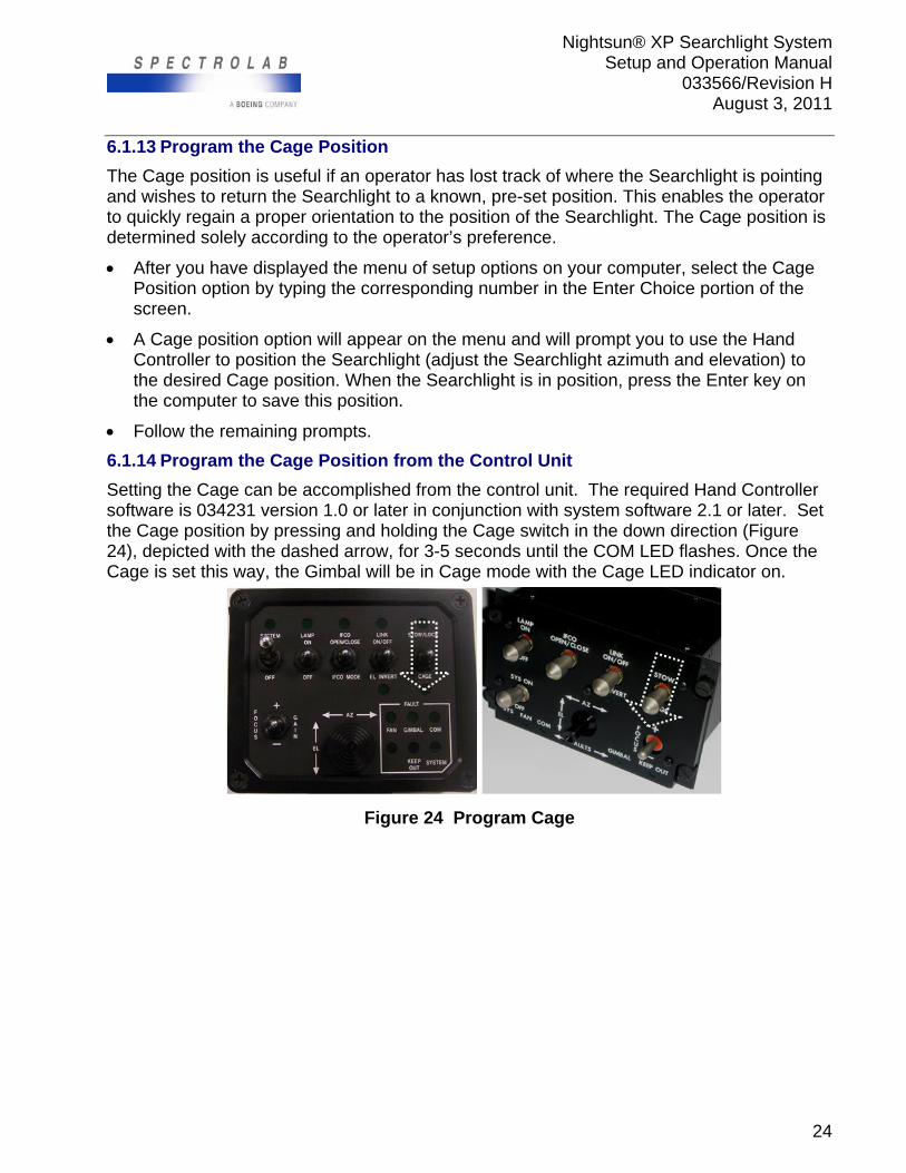
6.1.13 Program the Cage Position
The Cage position is useful if an operator has lost track of where the Searchlight is pointing and wishes to return the Searchlight to a known, pre-set position. This enables the operator to quickly regain a proper orientation to the position of the Searchlight. The Cage position is determined solely according to the operator’s preference.
After you have displayed the menu of setup options on your computer, select the Cage Position option by typing the corresponding number in the Enter Choice portion of the screen.
A Cage position option will appear on the menu and will prompt you to use the Hand Controller to position the Searchlight (adjust the Searchlight azimuth and elevation) to the desired Cage position. When the Searchlight is in position, press the Enter key on the computer to save this position.
Follow the remaining prompts.
6.1.14 Program the Cage Position from the Control Unit
Setting the Cage can be accomplished from the control unit. The required Hand Controller software is 034231 version 1.0 or later in conjunction with system software 2.1 or later. Set the Cage position by pressing and holding the Cage switch in the down direction (Figure 24), depicted with the dashed arrow, for 3-5 seconds until the COM LED flashes. Once the Cage is set this way, the Gimbal will be in Cage mode with the Cage LED indicator on.
Figure 24 Program Cage
Nightsun® XP Searchlight System Setup and Operation Manual
033566/Revision H August 3, 2011
25
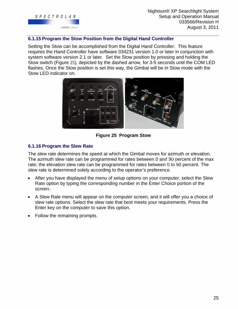
6.1.15 Program the Stow Position from the Digital Hand Controller
Setting the Stow can be accomplished from the Digital Hand Controller. This feature requires the Hand Controller have software 034231 version 1.0 or later in conjunction with system software version 2.1 or later. Set the Stow position by pressing and holding the Stow switch (Figure 25), depicted by the dashed arrow, for 3-5 seconds until the COM LED flashes. Once the Stow position is set this way, the Gimbal will be in Stow mode with the Stow LED indicator on.
Figure 25 Program Stow 6.1.16 Program the Slew Rate
The slew rate determines the speed at which the Gimbal moves for azimuth or elevation. The azimuth slew rate can be programmed for rates between 0 and 90 percent of the max rate; the elevation slew rate can be programmed for rates between 0 to 90 percent. The slew rate is determined solely according to the operator’s preference.
After you have displayed the menu of setup options on your computer, select the Slew Rate option by typing the corresponding number in the Enter Choice portion of the screen.
A Slew Rate menu will appear on the computer screen, and it will offer you a choice of slew rate options. Select the slew rate that best meets your requirements. Press the Enter key on the computer to save this option.
Follow the remaining prompts.
Nightsun® XP Searchlight System Setup and Operation Manual
033566/Revision H August 3, 2011
26
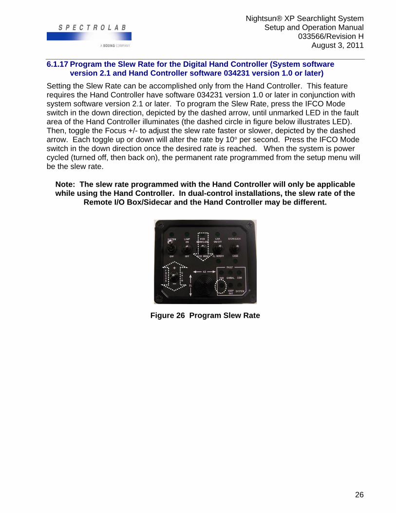
6.1.17 Program the Slew Rate for the Digital Hand Controller (System software version 2.1 and Hand Controller software 034231 version 1.0 or later)
Setting the Slew Rate can be accomplished only from the Hand Controller. This feature requires the Hand Controller have software 034231 version 1.0 or later in conjunction with system software version 2.1 or later. To program the Slew Rate, press the IFCO Mode switch in the down direction, depicted by the dashed arrow, until unmarked LED in the fault area of the Hand Controller illuminates (the dashed circle in figure below illustrates LED). Then, toggle the Focus +/- to adjust the slew rate faster or slower, depicted by the dashed arrow. Each toggle up or down will alter the rate by 10° per second. Press the IFCO Mode switch in the down direction once the desired rate is reached. When the system is power cycled (turned off, then back on), the permanent rate programmed from the setup menu will be the slew rate.
Note: The slew rate programmed with the Hand Controller will only be applicable while using the Hand Controller. In dual-control installations, the slew rate of the
Remote I/O Box/Sidecar and the Hand Controller may be different.
Figure 26 Program Slew Rate
Nightsun® XP Searchlight System Setup and Operation Manual
033566/Revision H August 3, 2011
27
6.2 Mechanical Stops
The mounting location of the Nightsun® XP should be selected to minimize the ability of the Searchlight beam to be aimed in detrimental directions (at personnel, aircraft, or heat-sensitive materials). To prevent the beam from being aimed in detrimental directions (in azimuth and elevation), there are mechanical stops mounted inside the Gimbal mechanism. These can be positioned to limit the elevation range and the azimuth range to accommodate your particular installation. In addition to the mechanical stops, the Nightsun® XP has a secondary system of a programmable Keep Out zone. If the mechanical stop position is altered from the delivered configuration, make sure to re-calibrate the Gimbal. Calibration is performed using the menu of setup options or automatically for Gimbal software version 2.1 or later. The System Setup section instructs how to calibrate when mechanical stop adjustments are made. To verify the software version, follow instructions in the Setup Menu section of this manual. To calibrate with an older version of software, refer to the section entitled “Programmable Setup Options.”
!
Caution
Do not place fingers inside the Gimbal’s area of motion when the power is on.
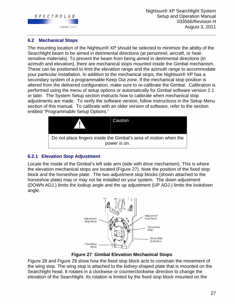
6.2.1 Elevation Stop Adjustment
Locate the inside of the Gimbal’s left side arm (side with drive mechanism). This is where the elevation mechanical stops are located (Figure 27). Note the position of the fixed stop block and the horseshoe plate. The two adjustment stop blocks (shown attached to the horseshoe plate) may or may not be installed on your system. The down adjustment (DOWN ADJ.) limits the lookup angle and the up adjustment (UP ADJ.) limits the lookdown angle.
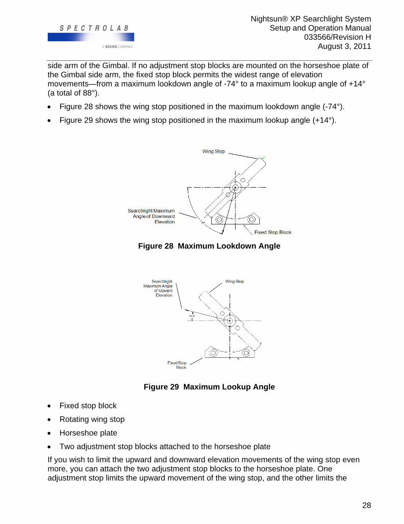
Figure 27 Gimbal Elevation Mechanical Stops Figure 28 and Figure 29 show how the fixed stop block acts to constrain the movement of the wing stop. The wing stop is attached to the kidney-shaped plate that is mounted on the Searchlight head. It rotates in a clockwise or counterclockwise direction to change the elevation of the Searchlight. Its rotation is limited by the fixed stop block mounted on the
Nightsun® XP Searchlight System Setup and Operation Manual
033566/Revision H August 3, 2011
28
side arm of the Gimbal. If no adjustment stop blocks are mounted on the horseshoe plate of the Gimbal side arm, the fixed stop block permits the widest range of elevation movements—from a maximum lookdown angle of -74° to a maximum lookup angle of +14° (a total of 88°).
Figure 28 shows the wing stop positioned in the maximum lookdown angle (-74°).
Figure 29 shows the wing stop positioned in the maximum lookup angle (+14°).
Figure 28 Maximum Lookdown Angle
Figure 29 Maximum Lookup Angle Fixed stop block
Rotating wing stop
Horseshoe plate
Two adjustment stop blocks attached to the horseshoe plate
If you wish to limit the upward and downward elevation movements of the wing stop even more, you can attach the two adjustment stop blocks to the horseshoe plate. One adjustment stop limits the upward movement of the wing stop, and the other limits the
Nightsun® XP Searchlight System Setup and Operation Manual
033566/Revision H August 3, 2011
29
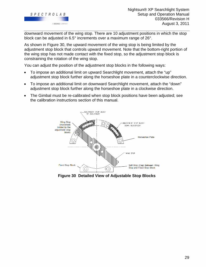
downward movement of the wing stop. There are 10 adjustment positions in which the stop block can be adjusted in 6.5° increments over a maximum range of 26°.
As shown in Figure 30, the upward movement of the wing stop is being limited by the adjustment stop block that controls upward movement. Note that the bottom-right portion of the wing stop has not made contact with the fixed stop, so the adjustment stop block is constraining the rotation of the wing stop.
You can adjust the position of the adjustment stop blocks in the following ways:
To impose an additional limit on upward Searchlight movement, attach the “up” adjustment stop block further along the horseshoe plate in a counterclockwise direction.
To impose an additional limit on downward Searchlight movement, attach the “down” adjustment stop block further along the horseshoe plate in a clockwise direction.
The Gimbal must be re-calibrated when stop block positions have been adjusted; see the calibration instructions section of this manual.
Figure 30 Detailed View of Adjustable Stop Blocks
Nightsun® XP Searchlight System Setup and Operation Manual
033566/Revision H August 3, 2011
30
6.2.1.1 Elevation Stop Adjustment for IFCO Configuration
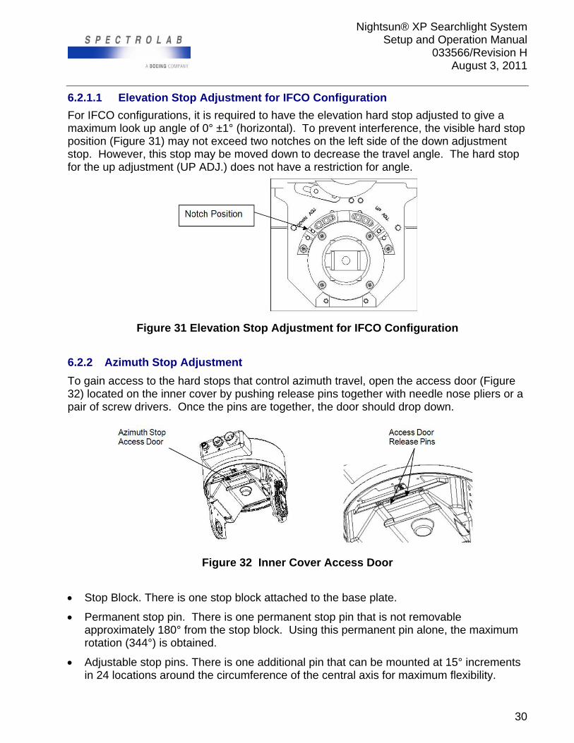
For IFCO configurations, it is required to have the elevation hard stop adjusted to give a maximum look up angle of 0° ±1° (horizontal). To prevent interference, the visible hard stop position (Figure 31) may not exceed two notches on the left side of the down adjustment stop. However, this stop may be moved down to decrease the travel angle. The hard stop for the up adjustment (UP ADJ.) does not have a restriction for angle.
Figure 31 Elevation Stop Adjustment for IFCO Configuration
6.2.2 Azimuth Stop Adjustment
To gain access to the hard stops that control azimuth travel, open the access door (Figure 32) located on the inner cover by pushing release pins together with needle nose pliers or a pair of screw drivers. Once the pins are together, the door should drop down.
Figure 32 Inner Cover Access Door
Stop Block. There is one stop block attached to the base plate.
Permanent stop pin. There is one permanent stop pin that is not removable approximately 180° from the stop block. Using this permanent pin alone, the maximum rotation (344°) is obtained.
Adjustable stop pins. There is one additional pin that can be mounted at 15° increments in 24 locations around the circumference of the central axis for maximum flexibility.
Nightsun® XP Searchlight System Setup and Operation Manual
033566/Revision H August 3, 2011
31
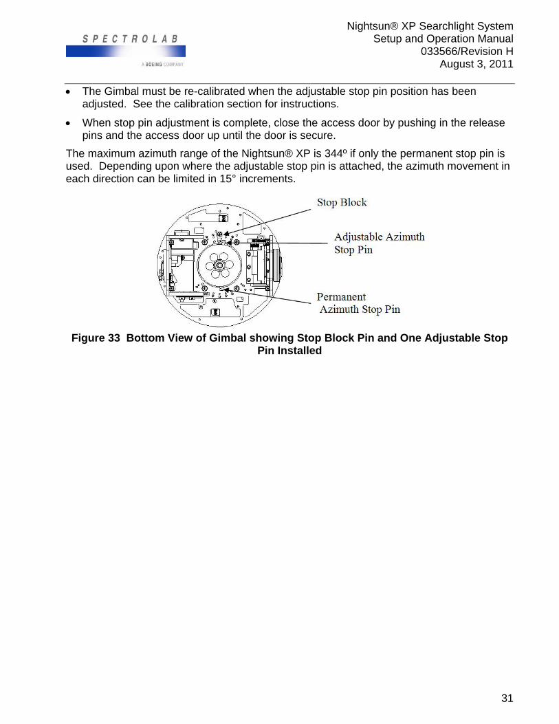
The Gimbal must be re-calibrated when the adjustable stop pin position has been adjusted. See the calibration section for instructions.
When stop pin adjustment is complete, close the access door by pushing in the release pins and the access door up until the door is secure.
The maximum azimuth range of the Nightsun® XP is 344º if only the permanent stop pin is used. Depending upon where the adjustable stop pin is attached, the azimuth movement in each direction can be limited in 15° increments.
Figure 33 Bottom View of Gimbal showing Stop Block Pin and One Adjustable Stop
Pin Installed
Nightsun® XP Searchlight System Setup and Operation Manual
033566/Revision H August 3, 2011
32
7.0 OPERATIONS
7.1 System Overview and Precautions
The Nightsun® XP includes a standard Hand Controller, Junction Box, Gimbal assembly, Searchlight, and cables. Optional equipment for system control is. System control can also be achieved with the components shown in section 3.0 and/or a linked system such as camera.
The altitude and orientation of the aircraft partly determine where the Searchlight is pointing, but a Nightsun® XP operator who is not piloting the craft can control the Searchlight and coordinate its movements skillfully to illuminate any point on the ground. A pilot who also operates the Searchlight, however, may risk devoting too much attention to events on the ground instead of avoiding navigational hazards such as power lines and antennas.
7.2 Preflight Checklist
The following procedures should be part of a routine preflight check for the Nightsun® XP:
By hand and visual inspection, make sure that the Searchlight head, Gimbal assembly, and mounting brackets are mechanically sound with safety locking wire installed on fasteners. Apply hand pressure to the Searchlight head in up, down, left, and right directions. The Gimbal assembly should maintain its position and should not rotate or move under hand pressure.
Make sure that the front window exterior is clean and not obstructed by dirt or moisture. Inspect the window under moderate to strong light such as daylight. The window
should be free of dirt, oil, moisture, water stains, insects, chips and pits, scratches and cracks. If you see significant amounts of dirt on the inside or outside surface of the glass, it must be cleaned.
Make sure that the Searchlight head and Gimbal cables are tightly connected and do not show evidence of cracking, fraying, etc.
Make sure that the cooling fan functions properly. Using the aircraft’s battery power if possible, put the Hand Controller’s System switch (not the Lamp switch) in the On position. Listen to the sound of the Searchlight cooling fan during operation; it should sound smooth and even.
Make sure that the azimuth and elevation control motors operate correctly. Using the aircraft’s battery power if possible, put the Hand Controller’s System switch in the On position, and use the joystick to check the azimuth (AZ) and elevation (EL) movement.
If the system has not been used recently, make sure that the lamp starts with full operating voltage applied to the Searchlight. Put the Lamp switch in the On position. This test may require running the aircraft engine at full rpm. Verify the system responds to command from the joystick (up, down, left, right).
Press and hold down the focus switch in one direction and verify the lamp is moving. Press the focus switch for the opposite direction and verify the lamp moves in the reverse direction.
Nightsun® XP Searchlight System Setup and Operation Manual
033566/Revision H August 3, 2011
33
It is recommended to power up system prior to flight if system use will be required.
7.3 System Control
The Nightsun® XP control can be accomplished with the following methods of user control: (1) standard digital Hand Controller, or Console Mount Control Panel (2) a Sidecar Control Box, which requires a Remote I/O box, and (3) position control by a device that links the system to enable synchronization of the Nightsun® XP with other control devices.
7.3.1 Command Switches and LED’s
System On/Off The System On/Off switch initializes power and communication between the control unit and Gimbal. When system is switched on, the system will begin the initialization routine as witnessed by the blinking indicators on the Hand Controller, and stop blinking once the system is ready for operation (approximately 15 seconds).
The Console Control Panel will have all LED’s steady for approximately the first 3 seconds of the initialization routine and blink until the system is ready for operation.
In the Off position, power is turned off; there is no auxiliary power, and no communication with the Gimbal and Searchlight is possible. It is recommended to stow the Searchlight before switching the system power off.
Lamp On/Off The Lamp On/Off switch is a switch that turns the Searchlight bulb on and off. In the Lamp On position, it turns the bulb on and the Lamp On indicator will illuminate. In the Off position it turns the lamp bulb off. The lamp may take up to 8 seconds to illuminate.
Link On/Off and EL Invert The Link On/Off and EL Invert switch has two functions: link and invert. The link command enables another device to take control of the Nightsun® XP. Consequently, the control unit will no longer control azimuth or elevation; instead, control will be transferred to the linked system’s controller.
The elevation invert command reverses the normal elevation response of the Gimbal mechanism. Consequently, an upward motion to the joystick will result in downward movement of the Searchlight, and a downward motion to the joystick will result in upward movement of the Searchlight. This feature is solely an operator preference.
Press the switch up once (the Link On position) to hand over control of the Nightsun® XP to a linked device and the Link indicator will illuminate. Press the switch up again to turn off the link to the other.
Press the switch down once (the EL Invert position) to reverse the normal elevation response of the Searchlight. The EL Invert indicator will illuminate. Press the switch down again to return the elevation response to the original setting.
Offset Calibration or In-Flight Calibration This feature is used during link mode to align the Searchlight’s beam to a target on the camera while in flight. It is strongly recommended that in order to achieve the best position matching during link mode, both the Searchlight and the linked system be mounted on the same planar axis, both horizontal to the ground. However, if this is not possible, the “In-Flight-Calibration” feature may be used to add a position offset to the Searchlight in order to match the Searchlight beam to the visible target on the camera. To access this function, do the following:
Turn link mode on by pressing the LINK switch on the control unit.
Nightsun® XP Searchlight System Setup and Operation Manual
033566/Revision H August 3, 2011
34
Press the LINK switch for approximately 3 seconds to enter In-Flight Calibration mode.
The digital Hand Controller will display a flashing LINK status during In-Flight Calibration mode. At this point, the user has control of the Searchlight position.
Calibrate the Searchlight position by pointing the Searchlight to the position that matches that of the target on the camera’s monitor. In other words, point the Searchlight’s beam to shine the target as displayed by the camera’s screen monitor.
To complete the In-Flight Calibration, press the LINK switch again for approximately 3 seconds. At this point, the Searchlight will maintain the calibrated position offset until a power reset is performed.
Offset Calibration (System software version 2.1 and Hand Controller software 034231 version 1.0 or later)
This procedure replaces the “3 second in, 3 second out” routine. While in Link mode, the user can offset the XP system position with the control unit at any time. This offset will match the position of the linked system at varying altitudes. To save this offset, unlink the system; otherwise, the offset will be reset when power cycled (system power off, then back on).
Stow/Lock and Cage The Stow/Lock and Cage switch has two functions. When the Searchlight is no longer needed, the Stow/Lock function enables an operator to place the Searchlight in a pre-set position that leaves it in standby mode. This inhibits the functionality of all command switches on the Hand Controller, but the Gimbal assembly and Searchlight remain in communication contact with the Hand Controller, which continues to receive status information. Place the Searchlight in Stow position before turning the System switch off. The Stow position is pre-programmable through the 9-pin setup port using a computer to display the menu of setup options. To program the Stow position, refer to the section entitled Programmable Setup Options and follow the instructions in the appropriate sub-sections.
To enter Stow/Lock mode, press the Stow/lock switch up. The Searchlight will move to the Stow position and the Stow/lock status indicator will illuminate when the system is in the programmed Stow position. At this time, the joystick is disabled from moving the Searchlight.
To exit Stow/Lock mode, press the Stow/Lock switch up again or press Cage and the system is ready to receive commands from the control unit.
The Cage command is useful when an operator loses track of where the Searchlight is pointing and wishes to return the Searchlight to a known, pre-set “home” position. When the Searchlight is in the Cage mode, all control unit commands remain active and responsive to operator input. The Cage position is determined solely by operator preference and is pre-programmable through the 9-pin setup port using a computer to display the menu of setup options. To program the Cage position, refer to the section entitled Programmable Setup Options and follow the instructions in the appropriate sub-sections.
To put the Searchlight in the Cage position, press the Cage switch.
Nightsun® XP Searchlight System Setup and Operation Manual
033566/Revision H August 3, 2011
35
The Searchlight will move to the pre-programmed and the Cage status indicator will illuminate.
Focus/Gain The Focus switch narrows or broadens the Searchlight beam. To focus (narrow) the light beam, press the Focus switch up (+) until the beam reaches the desired focus. To widen the beam press the switch down (-). The Gain function is not available at this time.
Joystick (AZ and EL) The joystick controls the azimuth and elevation of the Searchlight using natural hand movements. The rate of Searchlight movement is proportional to the amount of force applied to the joystick.
Azimuth. To adjust the Searchlight angle along the azimuth axis (AZ), apply force to the left or right on the joystick.
Elevation. To adjust the elevation angle of the Searchlight (EL), apply upward or downward force to the joystick.
7.3.2 Status/Fault indicators
The status indicators provide information about the operational status of the system.
Fan If the Fan indicator is lit, there is a malfunction in the Searchlight fan.
Gimbal If the Gimbal indicator is lit, there is a malfunction in the Gimbal or motion obstruction. To attempt to clear error, turn system off, and then back on.
Note: The Gimbal indicator may flash momentarily when press Lamp On until the lamp is On.
Communication When you first place the System switch in the On position, some of the indicators will blink until the initialization sequence is complete. However, be aware of the following conditions during normal operation:
COM blinking indicates a communication failure between the control unit and the Gimbal.
COM steady LED indicates a communication failure between the control unit and the Gimbal or an automatic system reset has occurred due to atypical to normal operations.
To attempt to regain communication, turn system off then back on.
Keep Out Keep Out zone is designed to avoid potentially dangerous exposure of the crew and aircraft to energy from the Searchlight beam. The Keep Out zone is pre-programmed through the setup port on the Gimbal before operation of the system. The Keep Out indicator is lit when the Searchlight has been positioned near a Keep Out zone.
System If the System indicator is lit, a general error has occurred in the system. As a result, the Searchlight lamp will automatically turn off. The operator should consider adjusting the position of the Searchlight for safety.
Nightsun® XP Searchlight System Setup and Operation Manual
033566/Revision H August 3, 2011
36
7.3.3 Automatic Self-Test
Every 30Hz (33 milliseconds), the Searchlight performs an automatic self-test. If a system error is revealed during the self-test, the System LED will light, but the lamp will not shut down. The operator must assess the urgency of the fault and decide when to turn the system off.
7.3.4 Link Protocol
Currently, the Nightsun® XP supports multiple protocols for external serial control interfaces linked to other systems: Specify the linking system at the time of purchase.
7.3.5 Link Protocol Auto-Detect (System and Hand Controller Version 2.1 or later)
Link Protocol Auto-Detect automatically determines the Linked system’s protocol. If a system is not detected, the Gimbal will move to position 0, 0 when in Link Mode. Link position offsets will be active and will work normally.
Refer to the Interface Control Document for the linked System to Nightsun® XP (document 032743) for additional information. It addresses the SLASS protocol.
7.3.6 Motion Obstruction
In the event of an obstruction in the normal motion of the Gimbal, a protection method is incorporated to prevent further damage. When the system has detected an obstruction to motion, a fault will occur resulting in the motors coming to a halt. At this time, the COM status indicator will illuminate steady to notify the operator of this condition. To proceed with operation, the operator must turn system power off and turn power on after 10-15 seconds. When the system power has been restored, a hard stop calibration will occur automatically.
Nightsun® XP Searchlight System Setup and Operation Manual
033566/Revision H August 3, 2011
37
8.0 Maintenance
This section provides maintenance information for the Nightsun® XP. Schedules provided in this manual are to be used as a baseline and minimal. It is at the user’s discretion to deviate depending on environment and application.
8.1 Daily Inspection and Maintenance Checklist
Every day (or before use), conduct a mechanical inspection of the Searchlight system to determine if it is flight worthy regardless of whether the Searchlight will be operated or not. Front Window:
Clean the outside of the window if there is any dirt, oil, moisture, water stains, or insects.
Inspect the inside of the window under moderate to strong light such as daylight. The window should be free of dirt, oil, moisture, water stains, insects, chips and pits, scratches and cracks. If there are significant amounts of dirt on the inside or outside surface of the glass, it must be cleaned.
Reflector/Collector Inspect the reflector for dust or discoloration. Look for easily visible dirt, or any
other object that may affect the light output performance or permanently damage the reflector.
Front Spider Assembly: Inspect the front spider assembly for any damage or other anomalies. Inspect the jack screws for any damage.
Inspect the Fan: Make sure that the air filter is not obstructed by dirt or other objects. Check the condition of the air filter. Make sure the fan cover is properly fastened to the Searchlight. Make sure the cooling fan functions properly. Listen to the sound of the fan
during operation: it should sound smooth and even. Inspect the arc lamp (bulb) for dirt and leaves, insects and spider webs, cracks in the
quartz envelope, and loosening of either of the electrodes. Cables and Connectors
Inspect the cables and connectors are tight not showing any signs of cracking, fraying or any other signs of damage.
8.2 Preflight Checklist
This section provides the preflight checklist for the Nightsun® XP as the minimal measures. It is at the user’s discretion to deviate depending on environment and application.
8.2.1 Visual Inspection
Before each flight verify the following: Front Window, is clean and not obstructed by dirt or any other objects. Searchlight mounting tight and secured. Safety Lanyards, Cables, Locking Wire are secured.
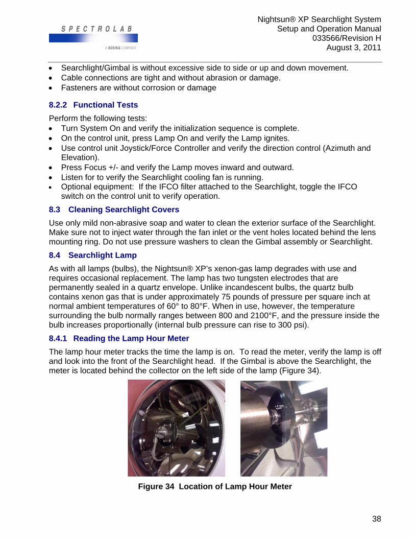
Nightsun® XP Searchlight System Setup and Operation Manual
033566/Revision H August 3, 2011
38
Searchlight/Gimbal is without excessive side to side or up and down movement. Cable connections are tight and without abrasion or damage. Fasteners are without corrosion or damage 8.2.2 Functional Tests
Perform the following tests: Turn System On and verify the initialization sequence is complete. On the control unit, press Lamp On and verify the Lamp ignites. Use control unit Joystick/Force Controller and verify the direction control (Azimuth and
Elevation). Press Focus +/- and verify the Lamp moves inward and outward. Listen for to verify the Searchlight cooling fan is running. Optional equipment: If the IFCO filter attached to the Searchlight, toggle the IFCO
switch on the control unit to verify operation.
8.3 Cleaning Searchlight Covers
Use only mild non-abrasive soap and water to clean the exterior surface of the Searchlight. Make sure not to inject water through the fan inlet or the vent holes located behind the lens mounting ring. Do not use pressure washers to clean the Gimbal assembly or Searchlight.
8.4 Searchlight Lamp
As with all lamps (bulbs), the Nightsun® XP’s xenon-gas lamp degrades with use and requires occasional replacement. The lamp has two tungsten electrodes that are permanently sealed in a quartz envelope. Unlike incandescent bulbs, the quartz bulb contains xenon gas that is under approximately 75 pounds of pressure per square inch at normal ambient temperatures of 60° to 80°F. When in use, however, the temperature surrounding the bulb normally ranges between 800 and 2100°F, and the pressure inside the bulb increases proportionally (internal bulb pressure can rise to 300 psi).
8.4.1 Reading the Lamp Hour Meter
The lamp hour meter tracks the time the lamp is on. To read the meter, verify the lamp is off and look into the front of the Searchlight head. If the Gimbal is above the Searchlight, the meter is located behind the collector on the left side of the lamp (Figure 34).
Figure 34 Location of Lamp Hour Meter
Nightsun® XP Searchlight System Setup and Operation Manual
033566/Revision H August 3, 2011
39
8.4.2 Lamp On Maintenance
The lamp on maintenance schedule should be every 3 months. Maintenance consists of turning on the lamp for a minimum of 20 minutes. The schedule of the maintenance can be adjusted according to use, installation and environment.
8.4.3 Assessing the Need for Lamp Replacement
A decision to replace a lamp should consider all factors—including overall system performance. The following characteristics can help to determine the need to replace a xenon lamp:
“Hard” lamp starts (the lamp requires more than 3 or 4 seconds to turn on)
Multiple flashes and “hard” lamp starts before actual startup (the lamp is near the end of its service life)
Development of a brownish tint on the inside surface of the bulb
A cracked or otherwise compromised bulb (leads to escape of the xenon gas)
Spectrolab Customer Service (800-936-4888) has replacement lamps available for purchase.
8.4.4 Lamp Explosion Hazard
The xenon-gas arc lamp must be handled with caution. Accidental breakage will result in an explosion of quartz particles because the gas inside the lamp is pressurized.
8.4.5 Lamp Replacement Procedure
8.4.5.1 Tools Required
#2 Phillips Screwdriver
8.4.5.2 Preparations
The lamp can be replaced without removing the Searchlight from the mount if there is a stable work platform.
Make sure that the lamp is at ambient temperature before beginning the replacement procedure.
Personnel who handle the xenon arc lamp or work on the Searchlight head with the front lens removed should wear protective clothing that includes a face shield, heavy leather jacket, and gloves.
Position the Searchlight so that the lens assembly is readily accessible (aim the Searchlight away from the aircraft or other obstructions). Then turn off all power to the Nightsun® XP (put the System switch in the Off position).
! Caution
Personnel who handle the arc lamp or work on the Searchlight head with the front lens removed should wear protective clothing that includes a face shield, heavy leather jacket, and gloves.
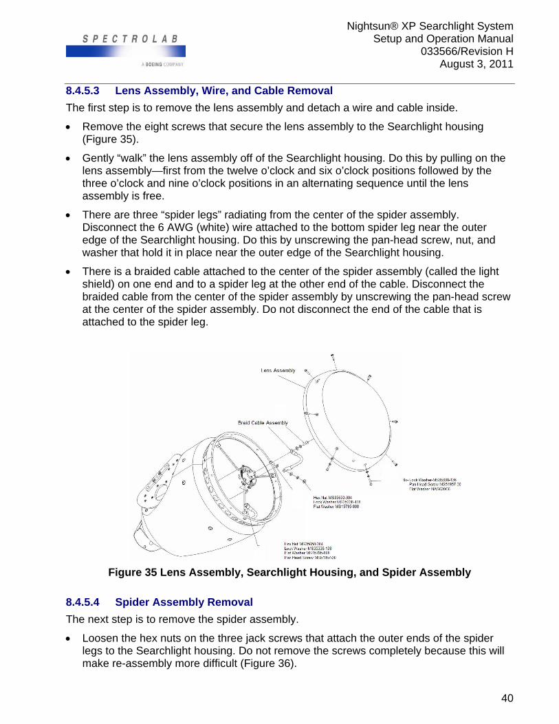
Nightsun® XP Searchlight System Setup and Operation Manual
033566/Revision H August 3, 2011
40
8.4.5.3 Lens Assembly, Wire, and Cable Removal
The first step is to remove the lens assembly and detach a wire and cable inside.
Remove the eight screws that secure the lens assembly to the Searchlight housing (Figure 35).
Gently “walk” the lens assembly off of the Searchlight housing. Do this by pulling on the lens assembly—first from the twelve o’clock and six o’clock positions followed by the three o’clock and nine o’clock positions in an alternating sequence until the lens assembly is free.
There are three “spider legs” radiating from the center of the spider assembly. Disconnect the 6 AWG (white) wire attached to the bottom spider leg near the outer edge of the Searchlight housing. Do this by unscrewing the pan-head screw, nut, and washer that hold it in place near the outer edge of the Searchlight housing.
There is a braided cable attached to the center of the spider assembly (called the light shield) on one end and to a spider leg at the other end of the cable. Disconnect the braided cable from the center of the spider assembly by unscrewing the pan-head screw at the center of the spider assembly. Do not disconnect the end of the cable that is attached to the spider leg.
Figure 35 Lens Assembly, Searchlight Housing, and Spider Assembly
8.4.5.4 Spider Assembly Removal
The next step is to remove the spider assembly.
Loosen the hex nuts on the three jack screws that attach the outer ends of the spider legs to the Searchlight housing. Do not remove the screws completely because this will make re-assembly more difficult (Figure 36).
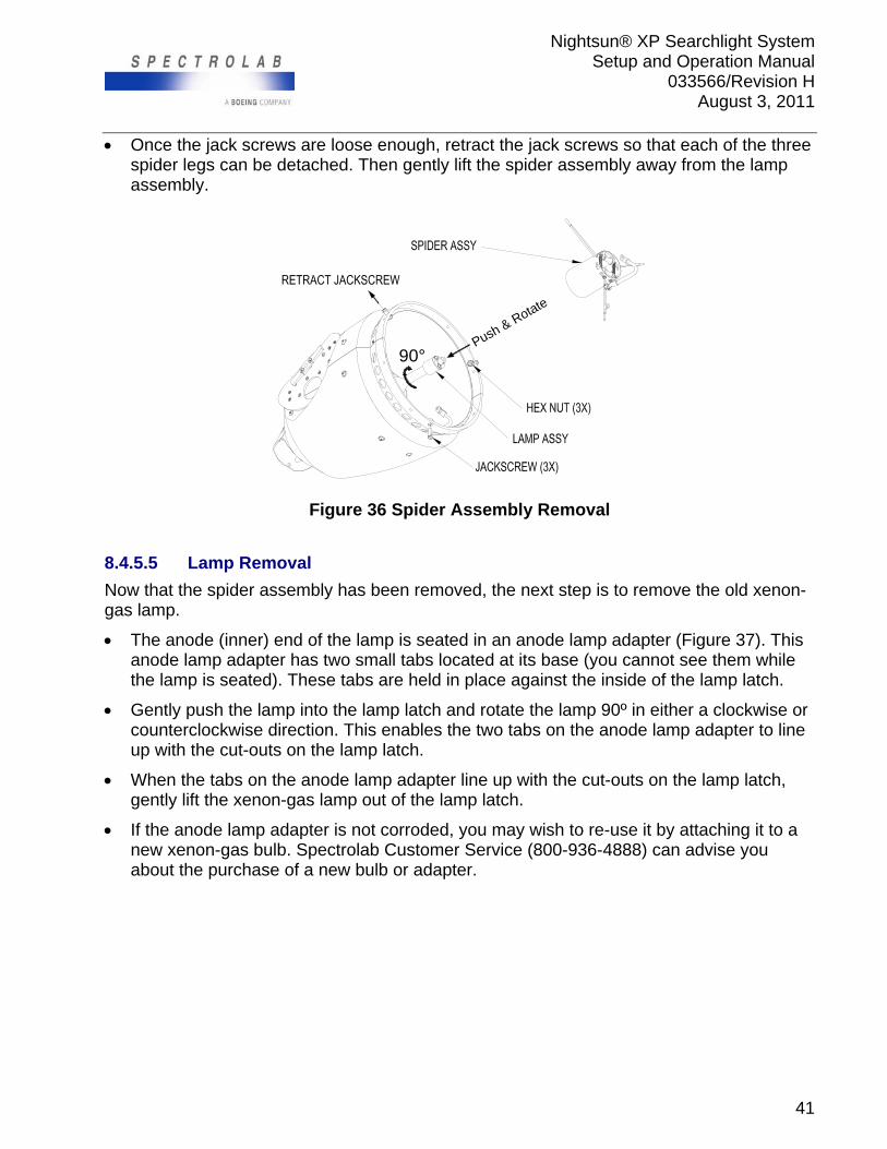
Nightsun® XP Searchlight System Setup and Operation Manual
033566/Revision H August 3, 2011
41
Once the jack screws are loose enough, retract the jack screws so that each of the three spider legs can be detached. Then gently lift the spider assembly away from the lamp assembly.
90°Push & Rotate
Figure 36 Spider Assembly Removal
8.4.5.5 Lamp Removal
Now that the spider assembly has been removed, the next step is to remove the old xenon-gas lamp.
The anode (inner) end of the lamp is seated in an anode lamp adapter (Figure 37). This anode lamp adapter has two small tabs located at its base (you cannot see them while the lamp is seated). These tabs are held in place against the inside of the lamp latch.
Gently push the lamp into the lamp latch and rotate the lamp 90º in either a clockwise or counterclockwise direction. This enables the two tabs on the anode lamp adapter to line up with the cut-outs on the lamp latch.
When the tabs on the anode lamp adapter line up with the cut-outs on the lamp latch, gently lift the xenon-gas lamp out of the lamp latch.
If the anode lamp adapter is not corroded, you may wish to re-use it by attaching it to a new xenon-gas bulb. Spectrolab Customer Service (800-936-4888) can advise you about the purchase of a new bulb or adapter.
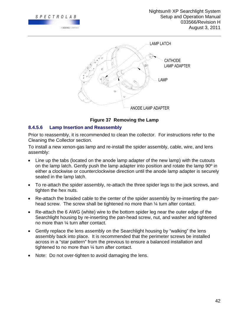
Nightsun® XP Searchlight System Setup and Operation Manual
033566/Revision H August 3, 2011
42
Figure 37 Removing the Lamp
8.4.5.6 Lamp Insertion and Reassembly
Prior to reassembly, it is recommended to clean the collector. For instructions refer to the Cleaning the Collector section.
To install a new xenon-gas lamp and re-install the spider assembly, cable, wire, and lens assembly:
Line up the tabs (located on the anode lamp adapter of the new lamp) with the cutouts on the lamp latch. Gently push the lamp adapter into position and rotate the lamp 90º in either a clockwise or counterclockwise direction until the anode lamp adapter is securely seated in the lamp latch.
To re-attach the spider assembly, re-attach the three spider legs to the jack screws, and tighten the hex nuts.
Re-attach the braided cable to the center of the spider assembly by re-inserting the pan-head screw. The screw shall be tightened no more than ¼ turn after contact.
Re-attach the 6 AWG (white) wire to the bottom spider leg near the outer edge of the Searchlight housing by re-inserting the pan-head screw, nut, and washer and tightened no more than ¼ turn after contact.
Gently replace the lens assembly on the Searchlight housing by “walking” the lens assembly back into place. It is recommended that the perimeter screws be installed across in a “star pattern” from the previous to ensure a balanced installation and tightened to no more than ¼ turn after contact.
Note: Do not over-tighten to avoid damaging the lens.
Nightsun® XP Searchlight System Setup and Operation Manual
033566/Revision H August 3, 2011
43
8.4.6 Collector Maintenance
Collector maintenance consists of inspection, cleaning and replacement. Daily inspection of the collector is recommended. Cleaning the collector should be scheduled every 3 months or 100 operation hours. The collector replacement should occur if the finish is affecting the light output. In environments with moisture such as rain or marine environments, cleaning may be required more often. The collector finish can be damaged if water stains and grime accumulate in conjunction with the heat of the lamp. The maintenance schedule can be adjusted according to use, installation and environment.
8.4.6.1 Cleaning the Collector
Remove the lens assembly and the lamp as described in Lamp Replacement section. Allow collector to cool before cleaning. Block opening in the back of collector with a towel to minimize the amount of water
that gets behind the collector into the interior of the light. Begin cleaning the collector by flushing it with clean, mineral-free water, preferably
distilled or de-ionized. A squirt bottle works very well for this task. Remove as much loose dust and dirt as possible with the flushing so abrasive particles will be removed which can damage the collector’s coating.
Rinse off solution with mineral-free water, preferably distilled or de-ionized, then rinse with Isopropyl Alcohol (IPA).
Dry with compressed gas stream or soft lint-free cloth.
8.5 Searchlight Fan Filter Maintenance
Fan filter maintenance consists of inspection and replacement. Inspect daily for objects that may limit air flow. The air filter should be replaced every 3 months or 100 operating hours. Dusty conditions require more frequent changes as opposed to humid, dust-free environments. Regular inspections will dictate the need to replace the filter. The fan filter is located on the rear of the Searchlight.
8.5.1 Fan Filter Replacement
Tools Required: #2 Phillips Screwdriver
To replace the filter:
Unscrew the three panel fasteners on the filter screen (Figure 38).
Lift out the filter screen; this releases the filter cover.
Remove the old filter and install a new one.
Place the filter cover over the filter, and re-install the filter screen. Tighten the panel fasteners.
To obtain filters, call Spectrolab Customer Service at 800-936-4888.
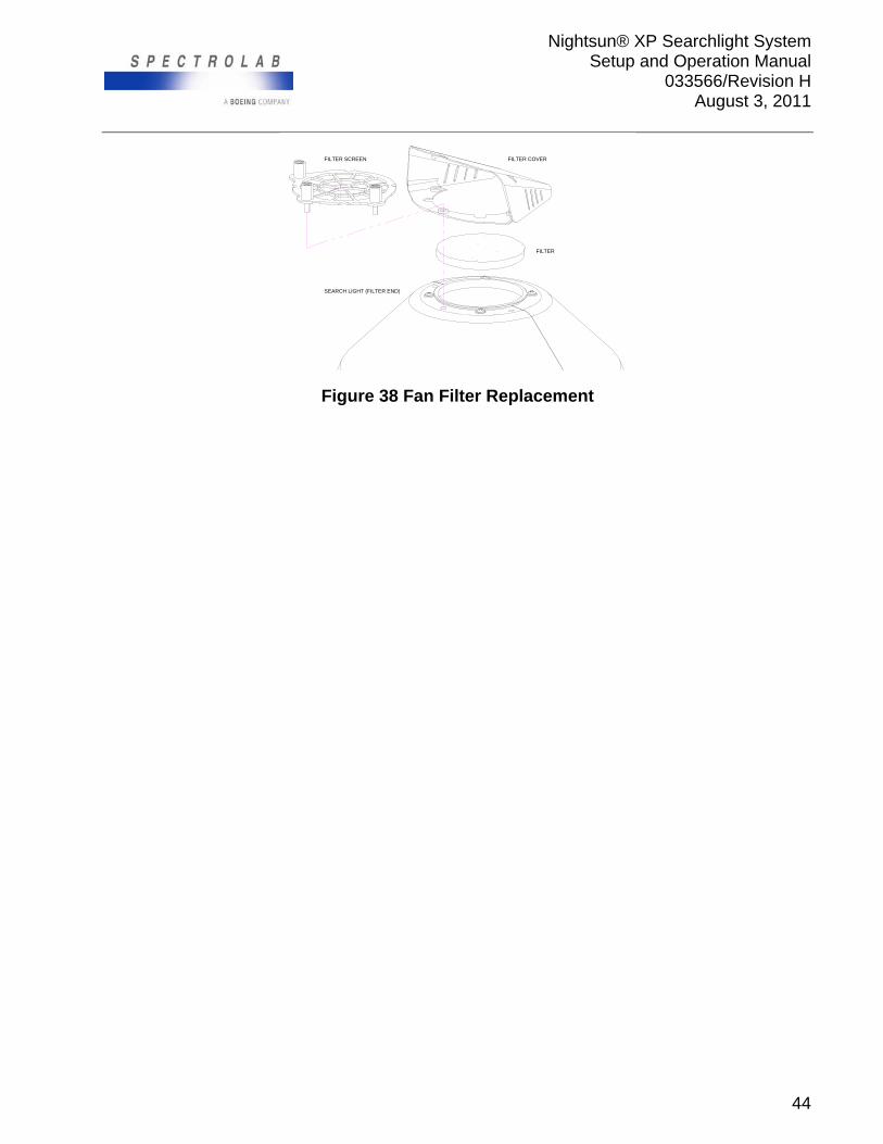
Nightsun® XP Searchlight System Setup and Operation Manual
033566/Revision H August 3, 2011
44
FILTER COVERFILTER SCREEN
FILTER
SEARCH LIGHT (FILTER END)
Figure 38 Fan Filter Replacement
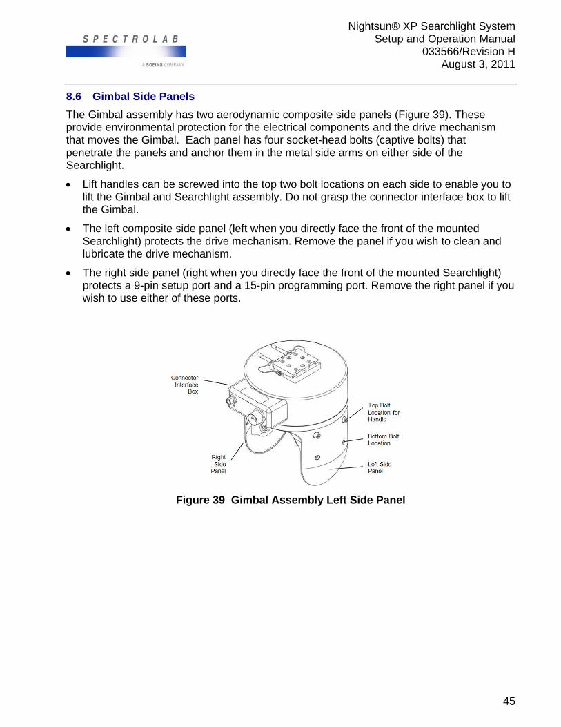
Nightsun® XP Searchlight System Setup and Operation Manual
033566/Revision H August 3, 2011
45
8.6 Gimbal Side Panels
The Gimbal assembly has two aerodynamic composite side panels (Figure 39). These provide environmental protection for the electrical components and the drive mechanism that moves the Gimbal. Each panel has four socket-head bolts (captive bolts) that penetrate the panels and anchor them in the metal side arms on either side of the Searchlight.
Lift handles can be screwed into the top two bolt locations on each side to enable you to lift the Gimbal and Searchlight assembly. Do not grasp the connector interface box to lift the Gimbal.
The left composite side panel (left when you directly face the front of the mounted Searchlight) protects the drive mechanism. Remove the panel if you wish to clean and lubricate the drive mechanism.
The right side panel (right when you directly face the front of the mounted Searchlight) protects a 9-pin setup port and a 15-pin programming port. Remove the right panel if you wish to use either of these ports.
Figure 39 Gimbal Assembly Left Side Panel
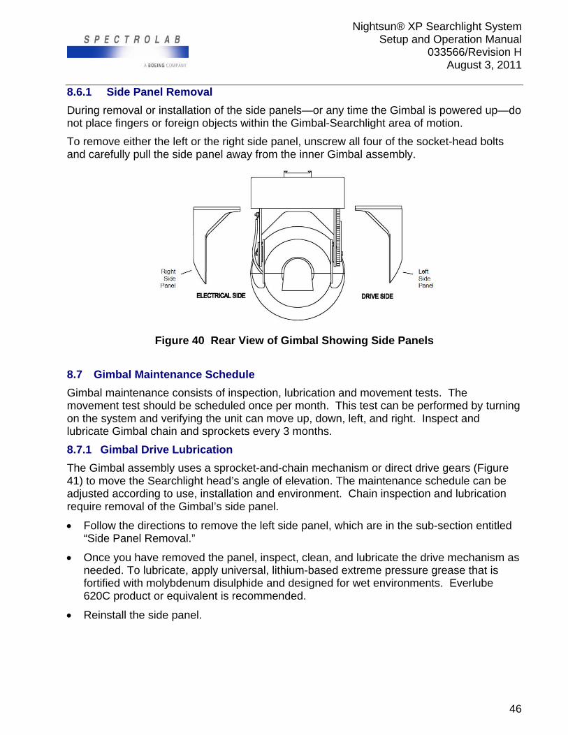
Nightsun® XP Searchlight System Setup and Operation Manual
033566/Revision H August 3, 2011
46
8.6.1 Side Panel Removal
During removal or installation of the side panels—or any time the Gimbal is powered up—do not place fingers or foreign objects within the Gimbal-Searchlight area of motion.
To remove either the left or the right side panel, unscrew all four of the socket-head bolts and carefully pull the side panel away from the inner Gimbal assembly.
Figure 40 Rear View of Gimbal Showing Side Panels
8.7 Gimbal Maintenance Schedule
Gimbal maintenance consists of inspection, lubrication and movement tests. The movement test should be scheduled once per month. This test can be performed by turning on the system and verifying the unit can move up, down, left, and right. Inspect and lubricate Gimbal chain and sprockets every 3 months.
8.7.1 Gimbal Drive Lubrication
The Gimbal assembly uses a sprocket-and-chain mechanism or direct drive gears (Figure 41) to move the Searchlight head’s angle of elevation. The maintenance schedule can be adjusted according to use, installation and environment. Chain inspection and lubrication require removal of the Gimbal’s side panel.
Follow the directions to remove the left side panel, which are in the sub-section entitled “Side Panel Removal.”
Once you have removed the panel, inspect, clean, and lubricate the drive mechanism as needed. To lubricate, apply universal, lithium-based extreme pressure grease that is fortified with molybdenum disulphide and designed for wet environments. Everlube 620C product or equivalent is recommended.
Reinstall the side panel.
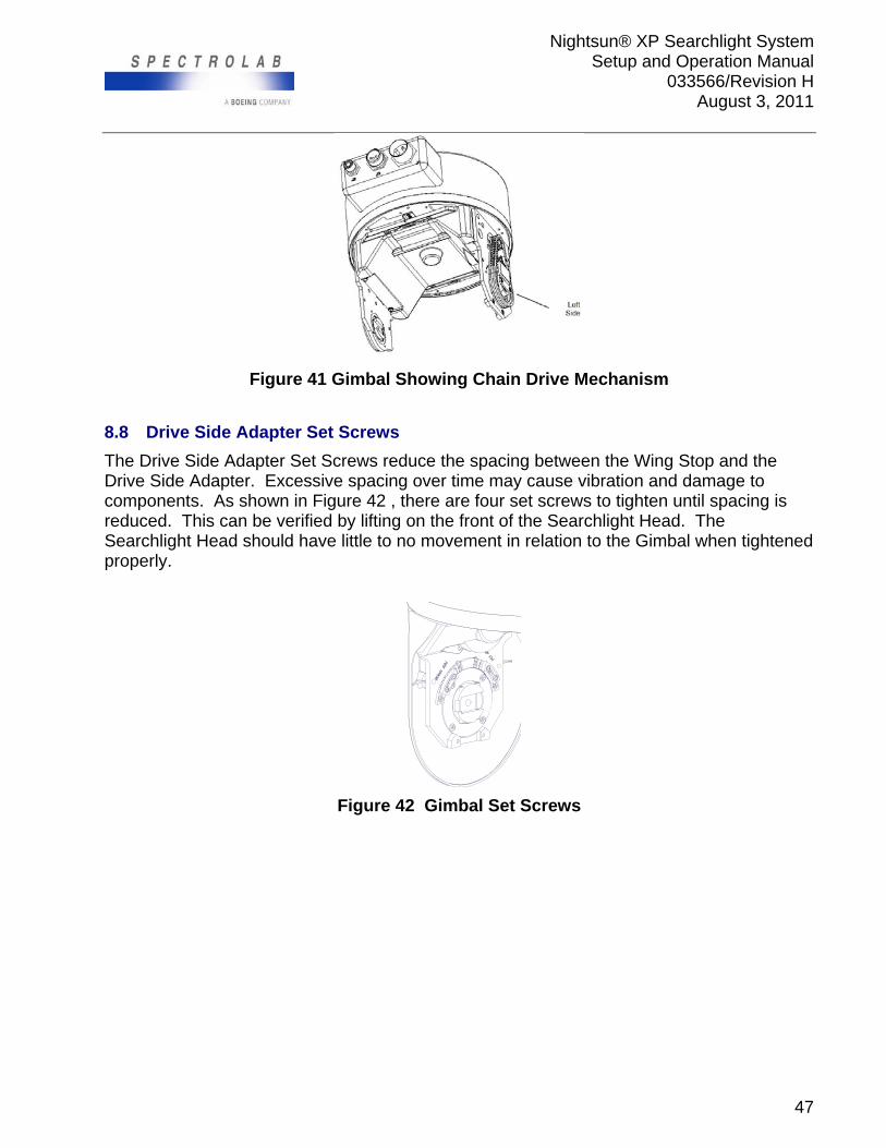
Nightsun® XP Searchlight System Setup and Operation Manual
033566/Revision H August 3, 2011
47
Figure 41 Gimbal Showing Chain Drive Mechanism
8.8 Drive Side Adapter Set Screws
The Drive Side Adapter Set Screws reduce the spacing between the Wing Stop and the Drive Side Adapter. Excessive spacing over time may cause vibration and damage to components. As shown in Figure 42 , there are four set screws to tighten until spacing is reduced. This can be verified by lifting on the front of the Searchlight Head. The Searchlight Head should have little to no movement in relation to the Gimbal when tightened properly.
Figure 42 Gimbal Set Screws
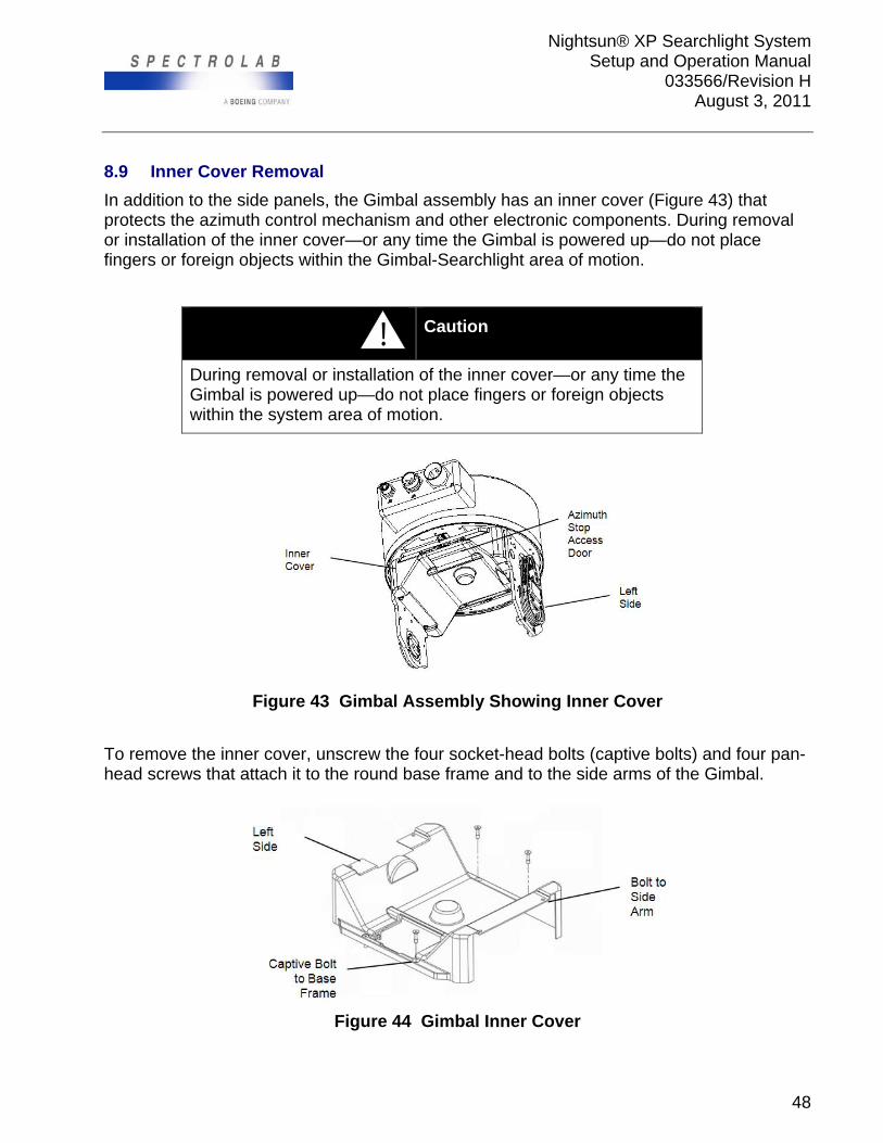
Nightsun® XP Searchlight System Setup and Operation Manual
033566/Revision H August 3, 2011
48
8.9 Inner Cover Removal
In addition to the side panels, the Gimbal assembly has an inner cover (Figure 43) that protects the azimuth control mechanism and other electronic components. During removal or installation of the inner cover—or any time the Gimbal is powered up—do not place fingers or foreign objects within the Gimbal-Searchlight area of motion.
! Caution
During removal or installation of the inner cover—or any time the Gimbal is powered up—do not place fingers or foreign objects within the system area of motion.
Figure 43 Gimbal Assembly Showing Inner Cover
To remove the inner cover, unscrew the four socket-head bolts (captive bolts) and four pan-head screws that attach it to the round base frame and to the side arms of the Gimbal.
Figure 44 Gimbal Inner Cover

Nightsun® XP Searchlight System Setup and Operation Manual
033566/Revision H August 3, 2011
49
9.0 CUSTOMER SERVICE
If you have a question or need assistance with a Nightsun® XP, please contact Spectrolab Customer Service at 800-936-4888. If you have questions or suggestions regarding this manual, please contact Spectrolab’s Illumination Products Engineering Department at 800-936-4888.
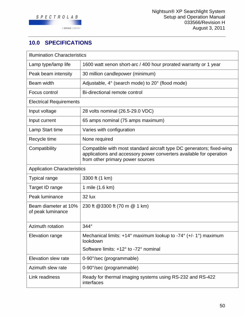
Nightsun® XP Searchlight System Setup and Operation Manual
033566/Revision H August 3, 2011
50
10.0 SPECIFICATIONS
Illumination Characteristics
Lamp type/lamp life 1600 watt xenon short-arc / 400 hour prorated warranty or 1 year
Peak beam intensity 30 million candlepower (minimum)
Beam width Adjustable, 4° (search mode) to 20° (flood mode)
Focus control Bi-directional remote control
Electrical Requirements
Input voltage 28 volts nominal (26.5-29.0 VDC)
Input current 65 amps nominal (75 amps maximum)
Lamp Start time Varies with configuration
Recycle time None required
Compatibility Compatible with most standard aircraft type DC generators; fixed-wing applications and accessory power converters available for operation from other primary power sources
Application Characteristics
Typical range 3300 ft (1 km)
Target ID range 1 mile (1.6 km)
Peak luminance 32 lux
Beam diameter at 10% of peak luminance
230 ft @3300 ft (70 m @ 1 km)
Azimuth rotation 344°
Elevation range Mechanical limits: +14° maximum lookup to -74° (+/- 1°) maximum lookdown
Software limits: +12° to -72° nominal
Elevation slew rate 0-90°/sec (programmable)
Azimuth slew rate 0-90°/sec (programmable)
Link readiness Ready for thermal imaging systems using RS-232 and RS-422 interfaces
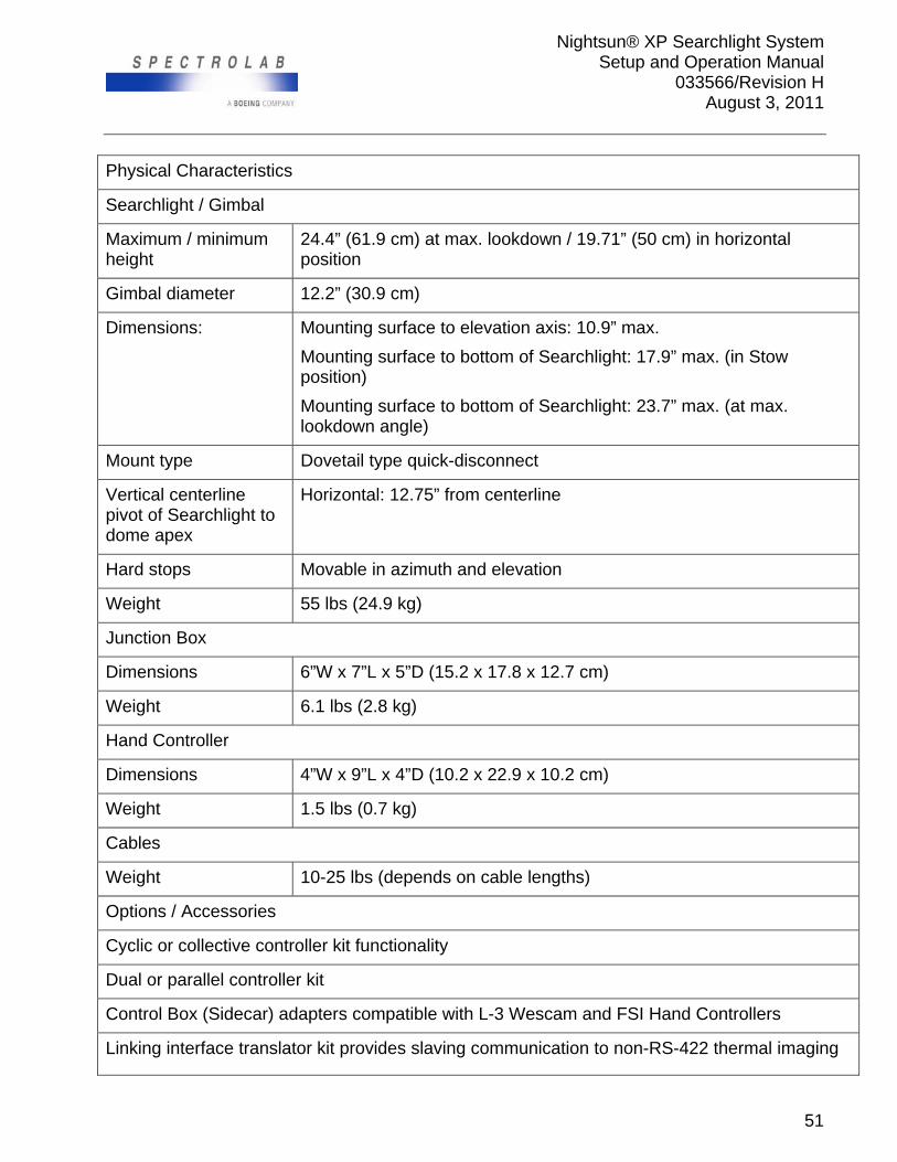
Nightsun® XP Searchlight System Setup and Operation Manual
033566/Revision H August 3, 2011
51
Physical Characteristics
Searchlight / Gimbal
Maximum / minimum height
24.4” (61.9 cm) at max. lookdown / 19.71” (50 cm) in horizontal position
Gimbal diameter 12.2” (30.9 cm)
Dimensions: Mounting surface to elevation axis: 10.9” max.
Mounting surface to bottom of Searchlight: 17.9” max. (in Stow position)
Mounting surface to bottom of Searchlight: 23.7” max. (at max. lookdown angle)
Mount type Dovetail type quick-disconnect
Vertical centerline pivot of Searchlight to dome apex
Horizontal: 12.75” from centerline
Hard stops Movable in azimuth and elevation
Weight 55 lbs (24.9 kg)
Junction Box
Dimensions 6”W x 7”L x 5”D (15.2 x 17.8 x 12.7 cm)
Weight 6.1 lbs (2.8 kg)
Hand Controller
Dimensions 4”W x 9”L x 4”D (10.2 x 22.9 x 10.2 cm)
Weight 1.5 lbs (0.7 kg)
Cables
Weight 10-25 lbs (depends on cable lengths)
Options / Accessories
Cyclic or collective controller kit functionality
Dual or parallel controller kit
Control Box (Sidecar) adapters compatible with L-3 Wescam and FSI Hand Controllers
Linking interface translator kit provides slaving communication to non-RS-422 thermal imaging
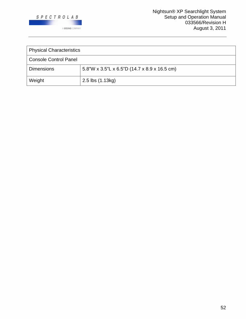
Nightsun® XP Searchlight System Setup and Operation Manual
033566/Revision H August 3, 2011
52
Physical Characteristics
Console Control Panel
Dimensions 5.8”W x 3.5”L x 6.5”D (14.7 x 8.9 x 16.5 cm)
Weight 2.5 lbs (1.13kg)
Nightsun® XP Searchlight System Setup and Operation Manual
033566/Revision H August 3, 2011
53
11.0 GLOSSARY AND ACRONYMS
Azimuth Refers to horizontal directions with respect to the Gimbal’s mounting plane; these correspond to compass directions
Chain and Sprocket Assembly Located on the left side arm of the Gimbal assembly (when facing directly into the mounted Searchlight) and protected by the composite panel
Communication Link Digital interchange system used to transmit and receive data
Connector Interface Box (Gimbal) Located on the rear of the Gimbal
Control Box (Sidecar) Alternative method of controlling the Nightsun® XP in addition to the standard Hand Controller; the Control Box (Sidecar) typically is located near the observer seat
CPU Central processing unit
Elevation Refers to vertical directions (up and down) with respect to the Gimbal’s mounting plane
EMI Electromagnetic interference
ESD Electrostatic sensitive device
Gimbal Assembly Also referred to as a “pan-tilt” mount, a mechanical structure that supports the Searchlight head and enables pointing of the light; it includes mechanical supports, motors, gears, and electronic equipment to control the light direction from a digital communication link; serves as an interface between the Searchlight head and Junction Box
Hand Controller Hand-held unit consisting of switches and status indicators that enable the operator to control the Nightsun® XP
IR Infrared
Junction Box also referred to as a “J-Box,” serves as a connection point between cables connecting other system components
Keep Out Zone Area and direction that a Nightsun® XP user can identify to prevent the Searchlight head from aiming at them; this forces the Searchlight to travel around them
Link Port (Junction Box) Located at connector J11 on the Junction Box, the link port is used to link the Nightsun® XP to the directional controller of another device; it also is used as a 28-volt auxiliary switch, power on/off, lamp on, and for serial communication
Mechanical Stop Located inside the Gimbal mechanism, a mechanical stop limits the range of movement (azimuth and elevation) to prevent the Searchlight beam from being aimed in detrimental directions; mechanical stops include adjustment stop blocks and fixed stop blocks (for elevation) and hard stops (for azimuth)
Nightsun® XP Searchlight System Setup and Operation Manual
033566/Revision H August 3, 2011
54
MTBF Mean time between failures
Nightsun® XP Searchlight System System consisting of the Searchlight head, Gimbal assembly, Junction Box, Hand Controller, and associated cables
Nightsun® XP Shortened form of Nightsun® XP Searchlight System
Programming Port (currently not available) Located on the right side of the Gimbal (when facing directly into the mounted Searchlight) behind the protective composite panel, this is a 15-pin connector that is used to program or update the Gimbal CPU software
Programmable Keep Out Zone Software-defined areas (directions) that a user can identify to prevent the Searchlight head from aiming at them; the Searchlight travels around these areas; the 9-pin setup port on the right side of the Gimbal (when facing directly into the mounted Searchlight) is behind the protective composite panel and is used to program the Keep Out zone
Remote Input/Output (I/O) Box Connected to the Control Box (Sidecar)
RFI Radio frequency interference
RPM Revolutions per minute
Searchlight Consists of a composite housing and front glass window containing a high-intensity xenon arc lamp, optical system, cooling fan, and electronics
Setup Port Located on the right side of the Gimbal (when facing directly into the mounted Searchlight) protected by the composite side panel, this has a 9-pin connector that is used to program the Stow position, Cage position, keep out zone, and slew rate; it is also used to view the settings, restore settings, and view current settings.
Sidecar Alternative method of controlling the Nightsun® XP in addition to the standard Hand Controller; the Control Box (Sidecar) typically is located near the observer seat
STC Supplemental Type Certificate
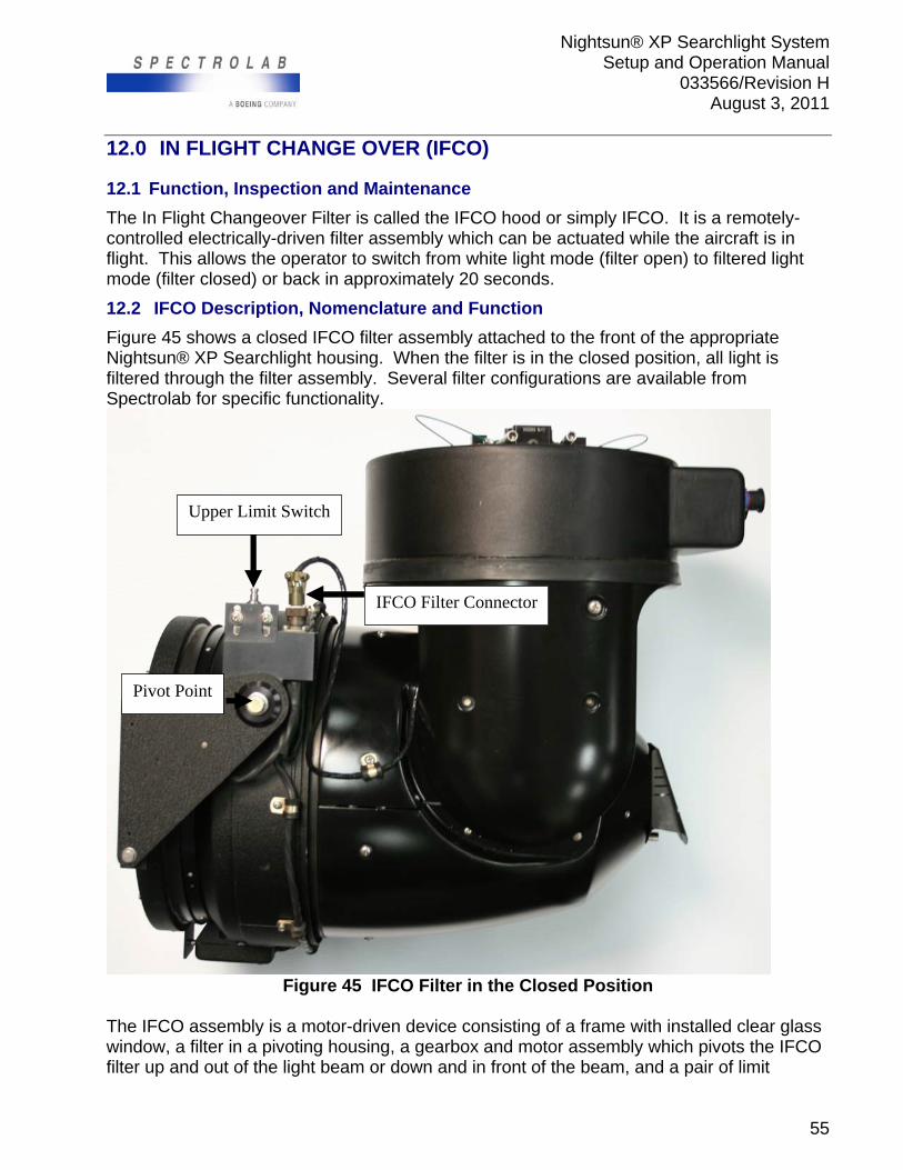
Nightsun® XP Searchlight System Setup and Operation Manual
033566/Revision H August 3, 2011
55
12.0 IN FLIGHT CHANGE OVER (IFCO)
12.1 Function, Inspection and Maintenance
The In Flight Changeover Filter is called the IFCO hood or simply IFCO. It is a remotely-controlled electrically-driven filter assembly which can be actuated while the aircraft is in flight. This allows the operator to switch from white light mode (filter open) to filtered light mode (filter closed) or back in approximately 20 seconds.
12.2 IFCO Description, Nomenclature and Function
Figure 45 shows a closed IFCO filter assembly attached to the front of the appropriate Nightsun® XP Searchlight housing. When the filter is in the closed position, all light is filtered through the filter assembly. Several filter configurations are available from Spectrolab for specific functionality.
Figure 45 IFCO Filter in the Closed Position
The IFCO assembly is a motor-driven device consisting of a frame with installed clear glass window, a filter in a pivoting housing, a gearbox and motor assembly which pivots the IFCO filter up and out of the light beam or down and in front of the beam, and a pair of limit
Pivot Point
IFCO Filter Connector
Upper Limit Switch
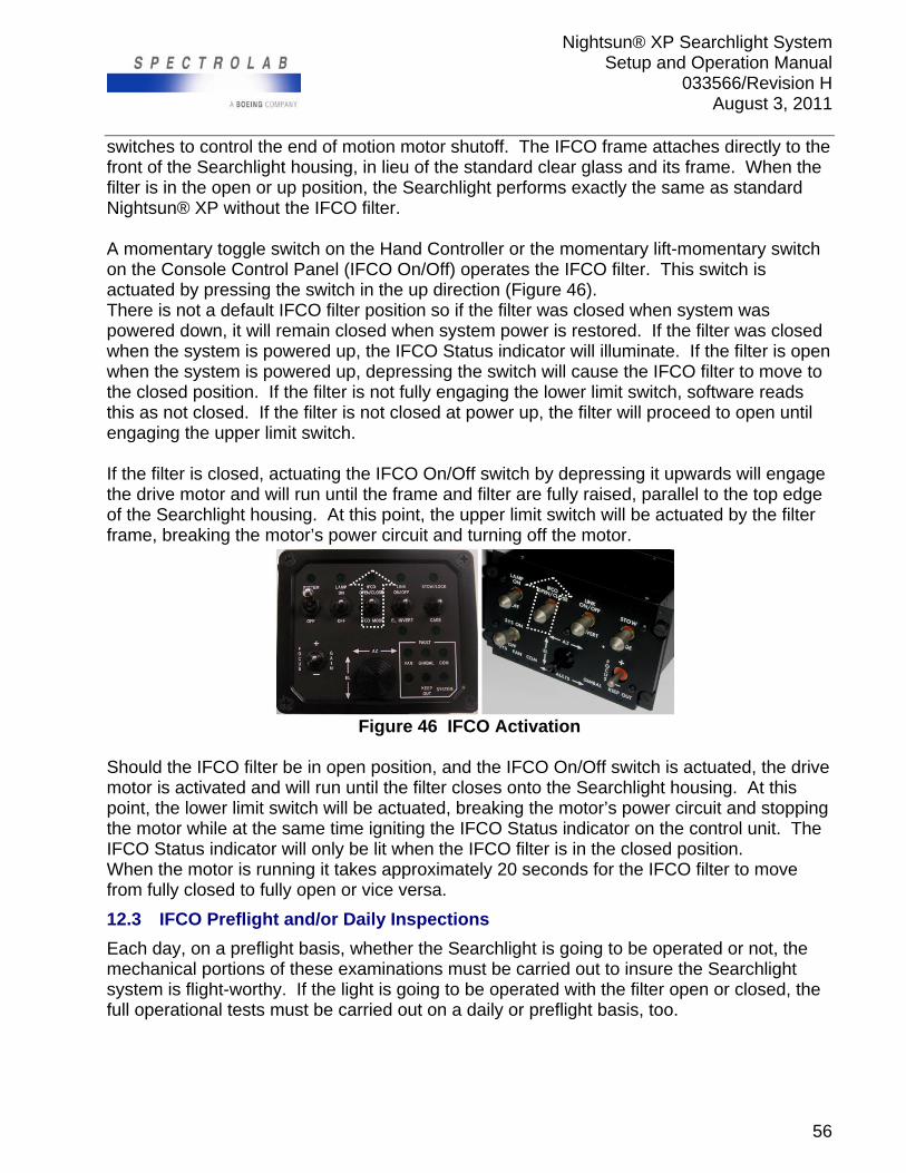
Nightsun® XP Searchlight System Setup and Operation Manual
033566/Revision H August 3, 2011
56
switches to control the end of motion motor shutoff. The IFCO frame attaches directly to the front of the Searchlight housing, in lieu of the standard clear glass and its frame. When the filter is in the open or up position, the Searchlight performs exactly the same as standard Nightsun® XP without the IFCO filter. A momentary toggle switch on the Hand Controller or the momentary lift-momentary switch on the Console Control Panel (IFCO On/Off) operates the IFCO filter. This switch is actuated by pressing the switch in the up direction (Figure 46). There is not a default IFCO filter position so if the filter was closed when system was powered down, it will remain closed when system power is restored. If the filter was closed when the system is powered up, the IFCO Status indicator will illuminate. If the filter is open when the system is powered up, depressing the switch will cause the IFCO filter to move to the closed position. If the filter is not fully engaging the lower limit switch, software reads this as not closed. If the filter is not closed at power up, the filter will proceed to open until engaging the upper limit switch. If the filter is closed, actuating the IFCO On/Off switch by depressing it upwards will engage the drive motor and will run until the frame and filter are fully raised, parallel to the top edge of the Searchlight housing. At this point, the upper limit switch will be actuated by the filter frame, breaking the motor’s power circuit and turning off the motor.
Figure 46 IFCO Activation
Should the IFCO filter be in open position, and the IFCO On/Off switch is actuated, the drive motor is activated and will run until the filter closes onto the Searchlight housing. At this point, the lower limit switch will be actuated, breaking the motor’s power circuit and stopping the motor while at the same time igniting the IFCO Status indicator on the control unit. The IFCO Status indicator will only be lit when the IFCO filter is in the closed position. When the motor is running it takes approximately 20 seconds for the IFCO filter to move from fully closed to fully open or vice versa.
12.3 IFCO Preflight and/or Daily Inspections
Each day, on a preflight basis, whether the Searchlight is going to be operated or not, the mechanical portions of these examinations must be carried out to insure the Searchlight system is flight-worthy. If the light is going to be operated with the filter open or closed, the full operational tests must be carried out on a daily or preflight basis, too.
Nightsun® XP Searchlight System Setup and Operation Manual
033566/Revision H August 3, 2011
57
12.3.1 Overall Mechanical Inspection of IFCO components:
12.3.1.1 Check Wiring Harness
Check the wiring harness from Gimbal to IFCO filter connector tightness, wires are in good condition, wire routing and jacketing. There must be no chaffed wires; wire jacketing must allow full left-right and up-down motion of the Searchlight and wires must not be pulled tight at the extreme ends of motion. On IFCO filter assembly, verify all wire insulation is sound; all wires are secured with clamps and wire ties. Limit switches boots are soft and pliable. Limit switches are solidly screwed in place.
12.3.1.2 Check All Mechanical Components:
IFCO filter clutch is tight All fasteners are tight, lock wires in place IFCO filter gasket soft, pliable, not torn
12.3.1.3 Verify the IFCO Filter Assembly and Filter Are Clean
The filter may need cleaning on a daily basis, depending on operating conditions. Since it is exposed to the full slipstream, it will accumulate dust, insects, and other contaminants from the atmosphere. For best performance it must be as clean as a freshly-cleaned windshield (windscreen). The IFCO filter may be cleaned with any liquid, non-abrasive glass cleaner. The optical coating on the optional filters is extremely durable, but it can be damaged by the use of abrasive cleaners. If the filter is extremely dirty, soap and water may be used as a first level pre-cleaning, followed by a glass cleaner. If a purpose-formulated glass cleaner is not available, soap and water will do, but a special effort must be made to remove all soap residues from the filter. The filter may be dried with paper towels, heated air or clean compressed air, or allowed to air dry after cleaning.
12.3.1.4 Verify IFCO Filter and Clear Glass Are Not Broken
Clean clear glass if needed. Clean the clear glass the same way the filter is cleaned.
12.3.1.5 Verify the IFCO Switch on the Hand Controller
Verify the IFCO switch on the Hand Controller works smoothly and is not broken.
12.3.2 Operational Tests
12.3.2.1 Operational Test
Turn the Searchlight system power ON and actuate the IFCO On/Off switch. If the IFCO filter is closed, the IFCO Status LED will light. If the IFCO filter is already open, the filter will proceed to close. When the IFCO filter is fully closed, the motor will stop running. At this point, with the system powered up, but the lamp not ignited, verify the filter closes properly. The filter should be fully closed at this time. Actuate the IFCO On/Off Switch to open the filter. The IFCO motor should start running and the filter will start to open. From fully closed to fully open position takes approximately 20 seconds.
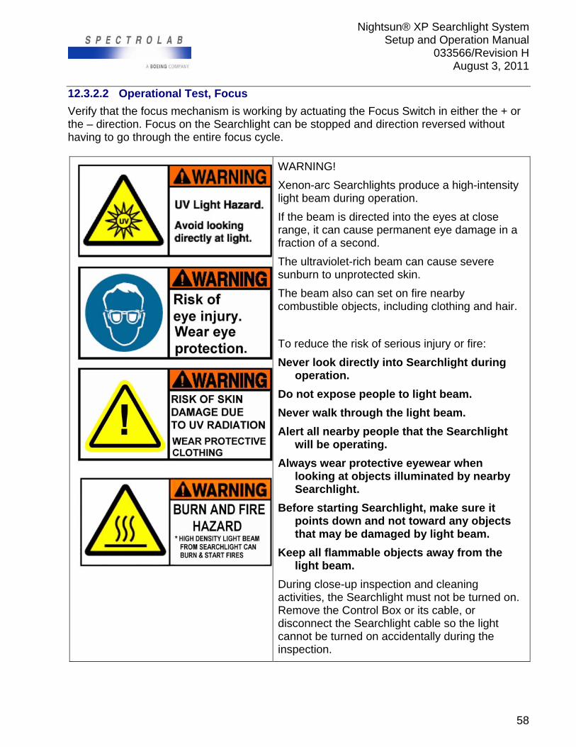
Nightsun® XP Searchlight System Setup and Operation Manual
033566/Revision H August 3, 2011
58
12.3.2.2 Operational Test, Focus
Verify that the focus mechanism is working by actuating the Focus Switch in either the + or the – direction. Focus on the Searchlight can be stopped and direction reversed without having to go through the entire focus cycle.
WARNING!
Xenon-arc Searchlights produce a high-intensity light beam during operation.
If the beam is directed into the eyes at close range, it can cause permanent eye damage in a fraction of a second.
The ultraviolet-rich beam can cause severe sunburn to unprotected skin.
The beam also can set on fire nearby combustible objects, including clothing and hair.
To reduce the risk of serious injury or fire:
Never look directly into Searchlight during operation.
Do not expose people to light beam.
Never walk through the light beam.
Alert all nearby people that the Searchlight will be operating.
Always wear protective eyewear when looking at objects illuminated by nearby Searchlight.
Before starting Searchlight, make sure it points down and not toward any objects that may be damaged by light beam.
Keep all flammable objects away from the light beam.
During close-up inspection and cleaning activities, the Searchlight must not be turned on. Remove the Control Box or its cable, or disconnect the Searchlight cable so the light cannot be turned on accidentally during the inspection.
Nightsun® XP Searchlight System Setup and Operation Manual
033566/Revision H August 3, 2011
59
12.3.2.3 Operational Test, Light Leaks
Open the IFCO filter. With the light pointed down or towards a non-flammable target, following normal operating and safety procedures, start the Searchlight and let it run for one to two minutes to warm up. With the Searchlight warmed up and still running, engage the IFCO On/Off Switch to close the filter. The filter should start to move down. It will take approximately 20 seconds for it to close fully. When it closes completely, the motor will stop. At this time, verify gasket is fully seated around Searchlight housing. In a darkened area let the light run for two to five minutes, pointed in a safe direction towards a non-flammable, non-reflective target. From well off to the side of the light, look for light leaks coming through the Gimbal/Searchlight housing area. Verify there is no light leaking out the front of the light, around the Gimbal or at the rear of the Searchlight housing. 12.3.3 IFCO/IR Safety Precautions
If an infrared (IR) filter is used, the filtered beam of radiation emitted by the Searchlight is not easily detectable by the unaided human eye when the Searchlight is operating with the hood closed. For security patrols there should not be any white light leaks visible to the naked eye adapted to the darkness.
Although you cannot readily see the filtered IR radiation emitted by the Searchlight, it has sufficient intensity (and wavelength) to cause severe and irreparable eye damage. Observe all warnings during operation and testing of the In Flight Change Over (IFCO) filter.
All flight and ground personnel who may be exposed to a Searchlight operating with the filter in place at a distance of less than 125 feet should observe the following warning: Do not look directly at a Searchlight that may be operating in the infrared range unless you are certain that it is not pointed toward you or is more than 500 feet away.
12.4 Inspection Schedule
In addition to daily inspections on a pre-flight basis, the following should take place every 3 months/100 flight hours / 50 operational hours. 12.4.1 Electrical
Examine the flexible Control Box cable for chaffing, worn or missing insulation, proper tight fit of connector back shells and cord grips on cables. Examine wiring on IFCO filter. Examine wiring between aircraft and IFCO filter. Start Searchlight and operate IFCO filter while flexing all wires. Verify system works with all wires flexed to their extremes of motion. Use care as described above in WARNING statement whenever operating the Searchlight. 12.4.2 Switches
Examine the limit switches carefully and readjust or replace if necessary (reference the section entitled Adjusting Limit Swithes for instruction).

Nightsun® XP Searchlight System Setup and Operation Manual
033566/Revision H August 3, 2011
60
12.4.3 Mechanical
a) Test IFCO filter clutch. Breakaway torque should be set to 220-250 inch-lbs. Readjust if breakaway is below 200 or over 275 inch-lbs.
b) Verify pivot bearings are smooth, not rusty; verify motor runs smoothly, has no rust under boot. Replace or repair if needed.
12.5 IFCO Statement of Operation
An electrically-driven gearbox, identical except for motor RPM to the elevation and azimuth gearboxes, actuates the IFCO filter assembly. It contains a high-torque, bi-directional, permanent magnet DC gear motor. The direction of the motion is controlled by the input electrical polarity to the motor, derived from the toggle switch on the Hand Controller. Limit switches stop motion of the motor as the IFCO filter reaches the full open or closed position by opening the motor’s supply line. To allow reversal of the motor from the end of travel positions, reversing bypass diodes are included in the circuit, across the limit switches. (Reference IFCO Cabling Diagram P/N 033401-OEM).
12.6 IFCO Filter Assembly Adjustments
12.6.1 Adjusting Limit Switches
Both limit switches must be adjusted properly for the IFCO assembly to work properly and reliably. Both switches are adjusted by loosening two screws, moving either the switch or strike plate to the correct position, and then tightening the screws. 12.6.2 Adjusting Filter Frame and Gimbal to Mate with Tapered Gasket Sealing
Surface
This is an iterative adjustment which takes time and patience. If the sealing gasket cannot compensate for incorrect adjustment between the filter frame and the gasket surface, then light will leak out. To adjust the filter frame and gasket, proceed as follows:
1. Remove lock wire from hood adjustment screws on both sides of Searchlight. 2. Loosen all four screws about ½ to 1 turn each, so the filter frame can move with
respect to the pivot brackets. 3. Run the filter down to the closed position. Move the filter so its gasket is perfectly
centered on the tapered sealing surface. 4. Tighten the four screws. 5. Operate the filter. It should close fully without causing the gasket to fold under itself
or deflect more on one side or the other. 6. It may be necessary to readjust the CLOSED limit switch contact plate after adjusting
the filter seating position. The only way to determine this is to electrically actuate the filter using the Hand Controller. To readjust:
Install the light onto the aircraft. Turn on system power. Do not start the light at this time. Open the filter. Close the filter and observe if it closes smoothly and the motor stops running
as the gasket is compressed.
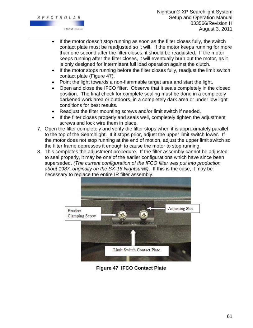
Nightsun® XP Searchlight System Setup and Operation Manual
033566/Revision H August 3, 2011
61
If the motor doesn’t stop running as soon as the filter closes fully, the switch contact plate must be readjusted so it will. If the motor keeps running for more than one second after the filter closes, it should be readjusted. If the motor keeps running after the filter closes, it will eventually burn out the motor, as it is only designed for intermittent full load operation against the clutch.
If the motor stops running before the filter closes fully, readjust the limit switch contact plate (Figure 47).
Point the light towards a non-flammable target area and start the light. Open and close the IFCO filter. Observe that it seals completely in the closed
position. The final check for complete sealing must be done in a completely darkened work area or outdoors, in a completely dark area or under low light conditions for best results.
Readjust the filter mounting screws and/or limit switch if needed. If the filter closes properly and seals well, completely tighten the adjustment
screws and lock wire them in place. 7. Open the filter completely and verify the filter stops when it is approximately parallel
to the top of the Searchlight. If it stops prior, adjust the upper limit switch lower. If the motor does not stop running at the end of motion, adjust the upper limit switch so the filter frame depresses it enough to cause the motor to stop running.
8. This completes the adjustment procedure. If the filter assembly cannot be adjusted to seal properly, it may be one of the earlier configurations which have since been superseded. (The current configuration of the IFCO filter was put into production about 1987, originally on the SX-16 Nightsun®). If this is the case, it may be necessary to replace the entire IR filter assembly.
Figure 47 IFCO Contact Plate

Nightsun® XP Searchlight System Setup and Operation Manual
033566/Revision H August 3, 2011
62
12.7 Nightsun® XP Elevation Adjustments
Elevation (look up) angle should be set so that the IFCO filter does not make contact with aircraft at any point. This can be accomplished by adjusting the elevation stop (half moon) on the Gimbal assembly.
12.8 Customer Service Contact
Contact Spectrolab Customer Service Department via telephone, toll free (800) 936-4888 or by email at [email protected] with any questions that you may have.
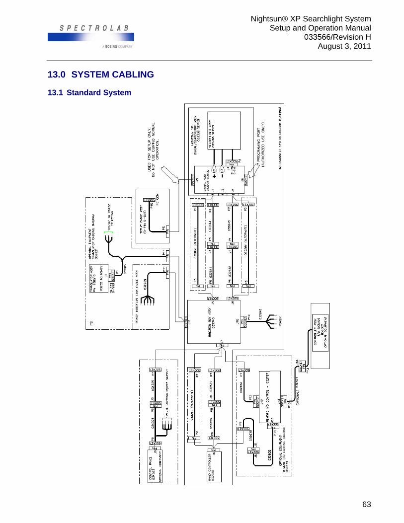
Nightsun® XP Searchlight System Setup and Operation Manual
033566/Revision H August 3, 2011
63
13.0 SYSTEM CABLING
13.1 Standard System
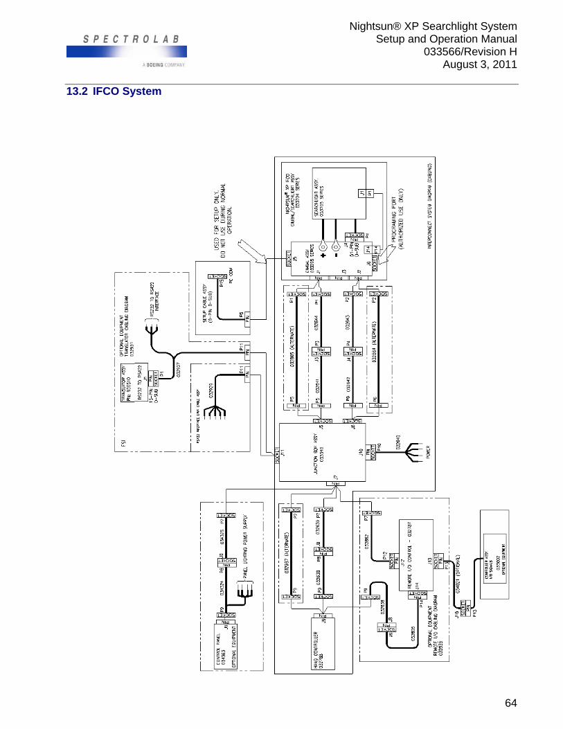
Nightsun® XP Searchlight System Setup and Operation Manual
033566/Revision H August 3, 2011
64
13.2 IFCO System
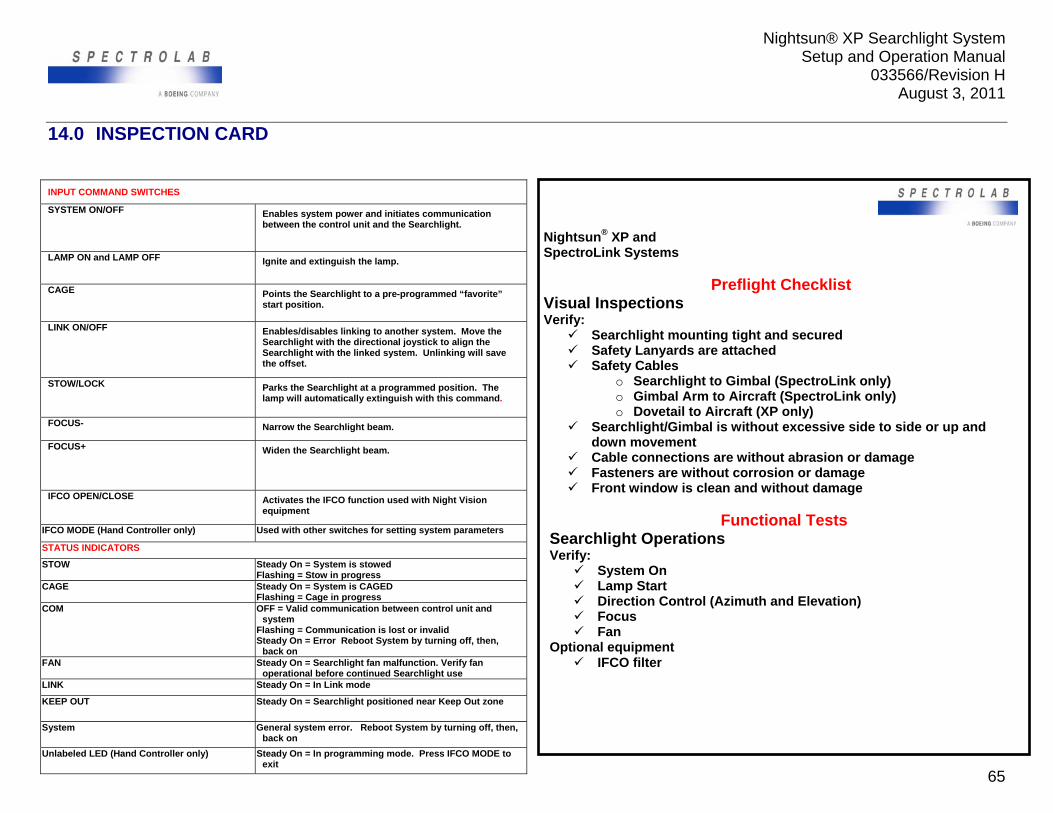
Nightsun® XP Searchlight System Setup and Operation Manual
033566/Revision H August 3, 2011
65
14.0 INSPECTION CARD
INPUT COMMAND SWITCHES
SYSTEM ON/OFF
Enables system power and initiates communication between the control unit and the Searchlight.
LAMP ON and LAMP OFF Ignite and extinguish the lamp.
CAGE
Points the Searchlight to a pre-programmed “favorite” start position.
LINK ON/OFF
Enables/disables linking to another system. Move the Searchlight with the directional joystick to align the Searchlight with the linked system. Unlinking will save the offset.
STOW/LOCK Parks the Searchlight at a programmed position. The lamp will automatically extinguish with this command.
FOCUS- Narrow the Searchlight beam.
FOCUS+ Widen the Searchlight beam.
IFCO OPEN/CLOSE Activates the IFCO function used with Night Vision equipment
IFCO MODE (Hand Controller only) Used with other switches for setting system parameters
STATUS INDICATORS
STOW Steady On = System is stowed Flashing = Stow in progress
CAGE Steady On = System is CAGED Flashing = Cage in progress
COM OFF = Valid communication between control unit and system
Flashing = Communication is lost or invalid Steady On = Error Reboot System by turning off, then,
back on FAN Steady On = Searchlight fan malfunction. Verify fan
operational before continued Searchlight use LINK Steady On = In Link mode
KEEP OUT Steady On = Searchlight positioned near Keep Out zone
System General system error. Reboot System by turning off, then, back on
Unlabeled LED (Hand Controller only) Steady On = In programming mode. Press IFCO MODE to exit
Nightsun® XP and SpectroLink Systems
Preflight Checklist Visual Inspections Verify:
Searchlight mounting tight and secured Safety Lanyards are attached Safety Cables
o Searchlight to Gimbal (SpectroLink only) o Gimbal Arm to Aircraft (SpectroLink only) o Dovetail to Aircraft (XP only)
Searchlight/Gimbal is without excessive side to side or up and down movement
Cable connections are without abrasion or damage Fasteners are without corrosion or damage Front window is clean and without damage
Functional Tests
Searchlight Operations Verify:
System On Lamp Start Direction Control (Azimuth and Elevation) Focus Fan
Optional equipment IFCO filter