Embed Size (px)
Citation preview

11/27/08
Laser Machining of CarbonLaser Machining of CarbonFibre ReinforcedFibre Reinforced
Composites and FEComposites and FEModellingModelling
Professor Lin Li
Laser Processing Research Centre
The University of Manchester
Email: [email protected]
In collaboration with SIMTech, Singapore

11/27/08
IntroductionIntroduction
• Material composition:carbon fibre, resin matrix
• Material Structure:Laminated with designed fibreorientation
• Properties of CFRP composite:High specific strength(strength/density)High specific modulus(modulus/density)
• Application of CFRP composites:Aerospace, Automotive, Marine,Sports goods, Infrastructure inweight-critical components. Airbusand Boeing have announced two newaircraft, the A350 and the B787, withcomposite content anticipated to beover 30% and 50%, respectively*.
Static
Static
Fatigue
Fatigue
Static
3
2
1
0
Rel
ativ
e st
ruct
ural
eff
icie
ncy
Aluminum(7075-T6)
Titanium(Ti-6Al-4V)
Carbon / Epoxy (AS / 3501-6)
Relative efficiency of aircraft materials*
Fatigue
* F.C Campbell, Manufacturing processes for advancedcomposites, Elsevier, UK, pp28
Example of CFRP woven cloth
* Hexcel Corporation annual report 2004

11/27/08
Machining of CompositesMachining of Composites
• Trimming and routing after curing forsmooth edge
• Drilling holes for fastener and acousticdamping(a single aircraft often requires manythousands of drilled holes in variouscomposite parts*)
• Half of manufacturing process is dedicatedto machining composite parts**
*http://www.compositesworld.com/hpc/issues/2004/November/636** http://www.mmsonline.com/articles/120501.html

11/27/08
• Non-contact process and no tool wearing• Easy for automation• HAZ and charring
• Best machining quality• Slow process
• Low temperature process, no heatdamage to matrix
• One jet head for all material andthickness, no tool exchange
• High noise and abrasive slurry arepotential hazardous to operator andenvironment
• Well developed process• Mechanical force induced delamination• Tool wear and dust
Advantages/disadvantages
Under development• Reduce charring/HAZ• Combining with other
technologies
• Combining withmechanical machining
• Increase pressure (700MPa)
• Combining withmechanical machining
• Tool design• Machining strategy
Development
Abrasivewaterjet
Mechanical
Ultrasonic
Laser
Techniques
Summary of Techniques for Machining CFRPSummary of Techniques for Machining CFRP

11/27/08
Challenges of Laser Machining of CompositesChallenges of Laser Machining of Composites
1.8543000330071050.00Graphite
1.251000350-50012000.2Polymer
Density(gcm-3)
Heat ofVaporization (J g-1)
Vaporization/Decomposition
temperature (oC)
Heat capacity(JKg-1K-1)
Conductivity(W/m/K)
Material
Thermal properties of fibres and matrix materials*:
* V. Tagliaferri, A. Di Ilio, I. Crivelli Visconti, Laser cutting of fibre reinforced polysters, Composite 16(14) 317-325, (1985)
Factors affect laser machining quality• High differences of thermal conductivities• High differences of vaporisation temperature• Laser beam cutting direction and fibre orientation
ChallengesMatrix recession, charring, heataffected zone
v v
parallel perpendicular

11/27/08
Work at Manchester/SingaporeWork at Manchester/Singapore
1. Laser machining CFRP composite using a 1 kWsingle mode fibre laser, DPSS lasers (IR, greenand UV), CO2 laser and excimer laser.
2. Examination of machining results
3. FE Modelling.
This presentation: Fibre laser cutting and 355 nmDPSS laser cutting

11/27/08
FibreFibre Laser Cutting Laser Cutting
500 µm 200 µm
20 µm200 µm
1 2
3 4

11/27/08
FibreFibre Laser Cutting Laser Cutting
0
200
400
600
800
1000
1200
20 30 45 50 55 60
Cutting Speed (mm/sec)
Kerf Width at Beam Entry
Kerf Width at Beam Exit
Fibre Pull Out
900 W laser power

11/27/08
Effect of GasEffect of Gas
N2
O2
He

11/27/08
Water Assisted Laser CuttingWater Assisted Laser Cutting
Power: 155Watt
0
0.2
0.4
0.6
0.8
1
1.2
1.4
1.6
1.8
Kerf Width Depth of Cut HAZ
Water AssistedNo Water

11/27/08
Water Assisted Laser CuttingWater Assisted Laser Cutting
Power: 270Watt
0
0.2
0.4
0.6
0.8
1
1.2
1.4
1.6
1.8
2
Kerf Width Depth of Cut HAZ
Water Assisted
No Water

11/27/08
Water Assisted Laser CuttingWater Assisted Laser Cutting
No water With water
900 W 50 mm/s
11/27/08
355 nm DPSS Laser Cutting355 nm DPSS Laser Cutting
Laser:Wavelength: 355 nmMaximum power: 10 WPulse frequency: 40 kHzBeam size: 20~25 µm
Galvanometer
F-theta lens
Workpiece
X
Y
Z
Galvanometer
Mirror 1
Mirror 2
Laser beam
Material:carbon fibre reinforced plastic(CFRP) compositesThickness: 0.3~7 mm
Atmosphere: Air

11/27/08
V= 50 mm/s V=200 mm/s V=800 mm/s
Drilling of Composite:Drilling of Composite: effects of scanning speedeffects of scanning speed
Hole size: 2 mm. Sample thickness 0.3 mm
• HAZ reducing with increase scanningspeed.
• Number of passer required to drill throughincrease with scanning speed.
• Time of drilling through decreasing withscanning speed.
0
5
10
15
20
25
30
35
40
45
50
-100 400 900
Scanning speed (mm/s)
Num
ber
of
pas
ses
requir
ed t
o d
rill
thro
ug
h
0
0.2
0.4
0.6
0.8
1
1.2
Tim
e of d
rilling th
rough (s)
drilling
through
without serious
damage
burning
not
drilling
throug
h

11/27/08
Drilling of Composite:Drilling of Composite: effects of laser beam scanning spacingseffects of laser beam scanning spacings
1-ring 2-ring 3-ring
spacingLaser beam path:
• Material removal rate is higher using 3-ring than 2-ring beam paths• Optimum beam spacing is 100 µm which is great than effective beam size 35 µm
0
10
20
30
40
50
60
70
80
90
100
0 0.1 0.2 0.3
Laser bream trace spacing (mm)N
um
ber
of
pas
ses
req
uir
ed t
o d
rill
th
rou
gh
0
4
8
12
16
20
24
28
32
36
40
Tim
e of d
rilling
thro
ug
h (s)
2-ring
3-ring
2-ring
3-ring
Hole size 2mm. Sample thickness 1 mm

11/27/08
Material Removal Mechanism:Material Removal Mechanism:Fibre ejection by heat conductionFibre ejection by heat conduction
1 2 3
M1 M2
T
Laser beam trace
M1 M2
Laser machining ofconventional material
Laser machining of CFRP
• Fibres are chopped intosmall pieces.
• Heat is conducted intoM1and M2.
• Heat is constrained in M1and M2.
• Surrounding polymer matrixare heat up to hightemperature.
• Polymer matrix loss itsholding power.
• Fibres are ejected.Fibre redeposited on sample surface
11/27/08
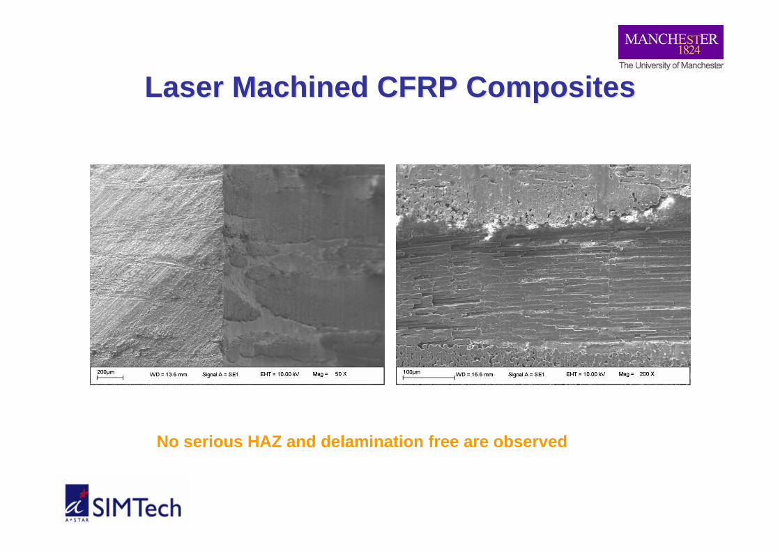
Laser Machined CFRP CompositesLaser Machined CFRP Composites
No serious HAZ and delamination free are observed

11/27/08
Bearing Strength of Drilled CompositesBearing Strength of Drilled Composites
0
2
4
6
8
10
12
0 2 4Displacement (mm)
Load
(kN
)
Laser drilledMechanical drilled
0
1
2
3
4
5
6
7
0 0.5 1 1.5 2 2.5
Displacement (mm)
Load
(kN
)
5.3 kN
Mechanical drilled Laser drilled
11/27/08
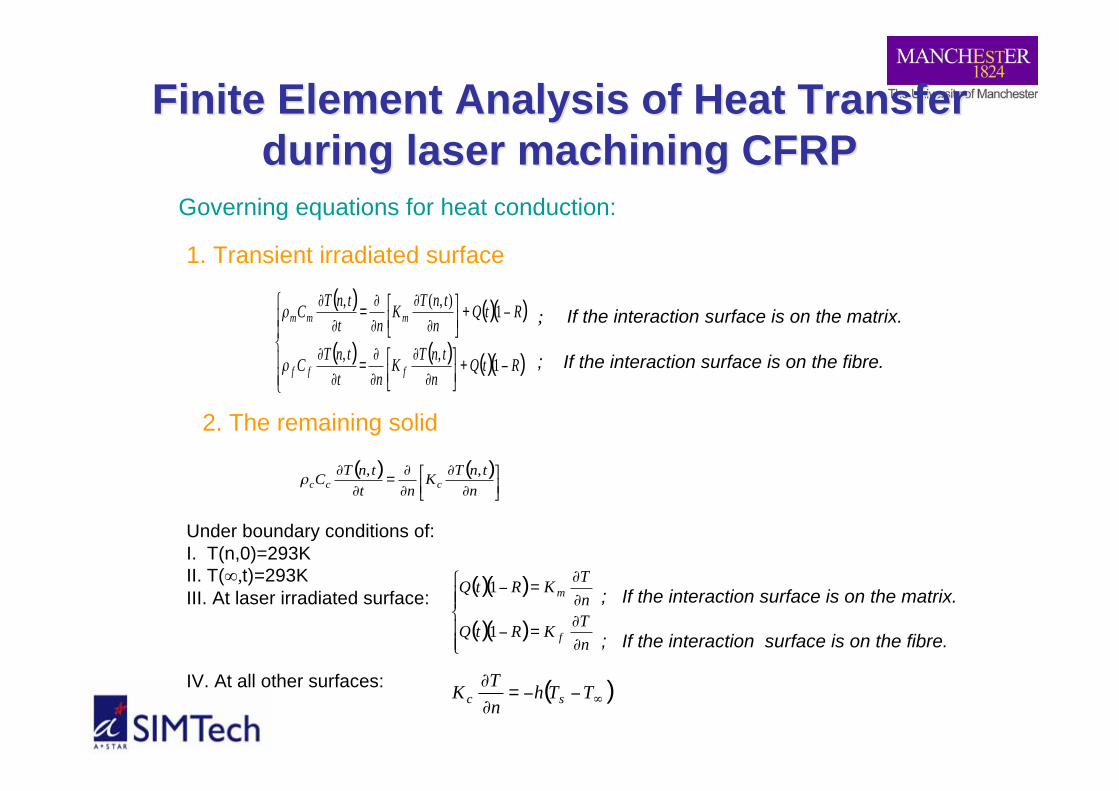
Finite Element Analysis of Heat TransferFinite Element Analysis of Heat Transferduring laser machining CFRPduring laser machining CFRP
Governing equations for heat conduction:
( ) ( )( )
( ) ( ) ( )( )!!
"
!!
#
$
%+&'
()*
+
,
,
,
,=
,
,
%+&'
()*
+
,
,
,
,=
,
,
RtQn
tnTK
nt
tnTC
RtQn
tnTK
nt
tnTC
fff
mmm
1,,
1),(,
-
-
1. Transient irradiated surface
; If the interaction surface is on the matrix.
; If the interaction surface is on the fibre.
2. The remaining solid
( ) ( )!"
#$%
&
'
'
'
'=
'
'
n
tnTK
nt
tnTC
ccc
,,(
( )( )
( )( )!!"
!!#
$
%
%=&
%
%=&
n
TKRtQ
n
TKRtQ
f
m
1
1 ; If the interaction surface is on the matrix.
; If the interaction surface is on the fibre.
Under boundary conditions of:I. T(n,0)=293KII. T(∞,t)=293KIII. At laser irradiated surface:
IV. At all other surfaces: ( )!""=
#
#TTh
n
TK
sc
11/27/08
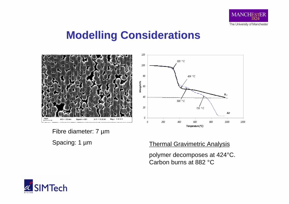
ModellingModelling Considerations Considerations
Fibre diameter: 7 µm
Spacing: 1 µm
0
20
40
60
80
100
120
0 200 400 600 800 1000 1200Temperature (°C)
Wei
gh
t%
320 º C
424 ºC
500 º C
715 º C
N 2
Air
Thermal Gravimetric Analysis
polymer decomposes at 424°C.Carbon burns at 882 °C

11/27/08
Laser Beam Reflectivity SpectrumLaser Beam Reflectivity Spectrum
0
5
10
15
20
25
30
20
0
24
4
28
8
33
2
37
6
42
0
46
4
50
8
55
2
59
6
64
0
68
4
72
8
77
2
81
6
86
0
90
4
94
8
99
2
10
36
10
80
Wavelength(nm)
Ref
lect
ivity
(%)

11/27/08
Material PropertiesMaterial Properties
6981153Decomposition Temperature (K)1884710Specific Heat(J.kg-1.K-1)
0.150Thermal conductivity in ambient
temperature(W.m-1.K-1)
12001800Density(kg/m3)40%60%Volume Fraction
EpoxyFibreProperty

11/27/08
Effect of Cutting Speed on Heat AffectedEffect of Cutting Speed on Heat AffectedZoneZone
400 mm/s (24 m/min) 800 mm/s (48 m/min)
Cut geometry pre-determined

11/27/08
Effect of Cutting Speed on Heat AffectedEffect of Cutting Speed on Heat AffectedZoneZone
50 mm/s 200 mm/s 800 mm/s
Cut geometry calculated

11/27/08
Comparison of FEA and Experiment ResultsComparison of FEA and Experiment Results
The HAZ overestimation observed from FEA canbe explained by thermal conductivity of fibresdecrease considerably at high temperatures.
Heat Affected Zone Ablation depth
Effect of speed on heat transfer mechanisms:Low speed: long heating time leads to low heatloss rate and more material removal.High speed: heat input decreasing results in heatloss rate increase and less material removal.
0
10
20
30
40
50
0 500 1000Scanning Speed (mm/s)
HA
Z (!
m)
FEA
EXP
µ
0
10
20
30
40
50
60
70
80
0 500 1000Scanning Speed (mm/s)
Abl
atio
n D
epth
(!m
)
FEA
EXP
µ

11/27/08
Effects of Laser BeamEffects of Laser BeamScanning SpacingsScanning Spacings
Simulation pathof the laser beam
Computationdomain (Red
section)
Previously CutGroove
100 µm spacing 150 µm spacing
75 µm Spacing
BlockEnd
Far Side
BeamPath
100 µm
BlockEnd
Far Side
Beam Path
150 µm
Block End
Far Side
Beam Path
75 µm

11/27/08
Effects of Laser BeamEffects of Laser BeamScanning SpacingsScanning Spacings
200 µm spacing

11/27/08
Removal DepthRemoval Depth
0
5
10
15
20
25
30
75 100 150
Exp.FEA
RemovalDepth (µm)
Beam Scanning Spacing (µm)

11/27/08
SummarySummary
• Minimum HAZ and delamination free are achieved by usingUV laser machining of CFRP composites.
• Bearing strengths of machined CFRP composites are similarbetween laser and mechanical drilled samples.
• Introduced New Material removal mechanism: combinationof laser ablation and heat conduction.
• Process speed could be increased by optimising laserscanning spaces.
• FEA prediction showed that the HAZ and ablation depthwere more sensitive to lower speed as compared to higherranges.
• FEA predicted that at 150µm distance i.e. 5 times the activebeam spot, the chip formation of fibres takes place.

11/27/08
The University of Manchester:Dr. S. Marimuthu,Mr. R. Negarestani,Dr. M. Sheikh,Dr. P. Mativenga,
Singapore (SIMTech)Dr. Zhongli Li,Mr. Pau Loong Chu,Dr. Hongyu Zheng,Dr. Gnian Cher Lim
Acknowledgements