Embed Size (px)
Citation preview
Learn more at altairhyperworks.com
Copyrights, Trademarks, Patents and Third Party Licenses
Intellectual Property Rights Notice:
Copyrights, Trademarks, Trade Secrets, Patents & Third Party Software Licenses
Altair® HyperWorks® v.2017
A Platform for Innovation®
Copyright© 1986-2016 Altair Engineering Inc. All Rights Reserved.
Special Notice: Pre-release versions of Altair software are provided ‘as is’, without warranty of any kind. Usage is strictly limited to non-production purposes.
HyperWorks® 2017 Products
HyperMesh® 1990-2016; HyperCrash® 2001-2016; OptiStruct® 1996-2016; RADIOSS® 1986-2016; HyperView® 1999-2016; HyperView Player® 2001-2016; HyperMath® 2007-2016; HyperStudy® 1999-2016; HyperGraph® 1995-2016; MotionView® 1993-2016; MotionSolve® 2002-2016; HyperForm® 1998-2016; HyperXtrude® 1999- 2016; Process Manager™ 2003-2016; Templex™ 1990-2016; TextView™ 1996-2016; MediaView™ 1999-2016; TableView™ 2013-2016; BatchMesher™ 2003-2016; HyperWeld® 2009-2016; HyperMold® 2009-2016; Manufacturing Solutions™ 2005-2016; solidThinking Inspire® 2017 2009-2016; solidThinking Evolve® 2017 1993-2016; Durability Director™ 2009-2016; Suspension Director™ 2009-2016; AcuSolve® 1997-2016; AcuConsole® 2006-2016; SimLab® 2004-2016; Virtual Wind Tunnel™ 2012-2016; FEKO® (©1999-2014 Altair Development S.A. (Pty) Ltd.; ©2014-2016 Altair Engineering, Inc.); ConnectMe™ 2014-2016.
Additional Altair Products:
Multiscale Designer™ 2011-2016; Flux™ v.12.2 1983-2016; InCa3D v.3.1 1996-2016; CDE v.2 2012-2016; Got-It v.3 2002-2016; WinProp v.14 2000-2016
Altair Packaged Solution Offerings (PSOs) Copyright© 2008-2016
Automated Reporting Director™ 2008-2016; GeoMechanics Director 2011-2016; Impact Simulation Director™ 2010-2016; Model Mesher Director™ 2010-2016; Model Verification Director™ 2013-2016; NVH Director™ 2010-2016; Squeak and Rattle Director™ 2012-2016; Virtual Gauge Director™ 2012-2016; Weight Analytics™ 2013-2016; Weld Certification Director™ 2014-2016
Altair Simulation Cloud Suite:
Simulation Manager™ 2003-2016; Compute Manager™ 2003-2016; Display Manager™ 2003–2016; and Process Manager™ 2003-2016.
Altair PBS Works™:
Compute Manager™ 2012-2016; Display Manager™ 2013-2016; PBS™ 1994-2016; PBS Pro™ 1994-2016; PBS Professional® 1994-2016; PBS Application Services™ 2008-2016; PBS Analytics™ 2008-2016; and PBS Desktop™ 2008-2012; e-Compute™ 2000-2010; OpenPBS® 1994-2003 and Personal PBS® 2008-2012.
Software products of solidThinking, Inc., a wholly owned subsidiary of Altair Engineering:
solidThinking Inspire® 2017 2009-2016; solidThinking Evolve® 2017 1993-2016; solidThinking Compose™ 2017 2007-2016; solidThinking Activate™ 2017 1989-2016; solidThinking Embed™ 2017

1989-2016; solidThinking Embed™ SE 2017 1989-2016; Click2Extrude™ Metal 2017 1996-2016; Click2Extrude™ Polymer 2017 1996-2016; Click2Cast® 14.0 2011-2016; Click2Form™ 2017 1998-2016; Envision™ 2013-2016.
ALTAIR ENGINEERING INC. Proprietary and Confidential. Contains Trade Secret Information.
Not for use or disclosure outside of Altair and its licensed clients. Information contained in Altair software shall not be decompiled, disassembled, “unlocked”, reverse translated, reverse engineered, or publicly displayed or publicly performed in any manner. Usage of the software is only as explicitly permitted in the end user software license agreement. Copyright notice does not imply publication.
Third party software licenses
AcuConsole contains material licensed from Intelligent Light (www.ilight.com) and used by permission.
Software Security Measures:
Altair Engineering Inc. and its subsidiaries and affiliates reserve the right to embed software security mechanisms in the Software for the purpose of detecting the installation and/or use of illegal copies of the Software. The Software may collect and transmit non-proprietary data about those illegal copies. Data collected will not include any customer data created by or used in connection with the Software and will not be provided to any third party, except as may be required by law or legal process or to enforce our rights with respect to the use of any illegal copies of the Software. By using the Software, each user consents to such detection and collection of data, as well as its transmission and use if an illegal copy of the Software is detected. No steps may be taken to avoid or detect the purpose of any such security mechanisms.
Technical Support
Altair provides comprehensive software support via web FAQs, tutorials, training classes, telephone, and e-mail.
Altair Support on the World Wide Web
The Altair web site is a valuable online companion to Altair software. Visit www.altairhyperworks.com for tips and tricks, training course schedules, training/tutorial videos, and other useful information.
Altair Training Classes
Altair training courses provide a hands-on introduction to our products, focusing on overall functionality. Courses are conducted at our main and regional offices or at your facility. If you are interested in training at your facility, please contact your account manager for more details. If you do not know who your account manager is, please send an e-mail to [email protected] and your account manager will contact you.
Telephone and e-mail
When contacting Altair support, please specify the product and version number you are using along with a detailed description of the problem. Many times, it is very beneficial for the support engineer to know what type of workstation, operating system, RAM, and graphics board you have, so please have that information ready. If you send an e-mail, please specify the workstation type, operating system, RAM, and graphics board information in the e-mail.
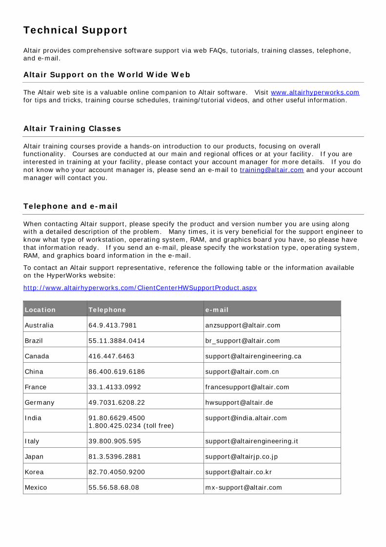
To contact an Altair support representative, reference the following table or the information available on the HyperWorks website:
http://www.altairhyperworks.com/ClientCenterHWSupportProduct.aspx
Location Telephone e-mail
Australia 64.9.413.7981 [email protected]
Brazil 55.11.3884.0414 [email protected]
Canada 416.447.6463 [email protected]
China 86.400.619.6186 [email protected]
France 33.1.4133.0992 [email protected]
Germany 49.7031.6208.22 [email protected]
India 91.80.6629.4500 1.800.425.0234 (toll free)
Italy 39.800.905.595 [email protected]
Japan 81.3.5396.2881 [email protected]
Korea 82.70.4050.9200 [email protected]
Mexico 55.56.58.68.08 [email protected]

New Zealand 64.9.413.7981 [email protected]
North America 248.614.2425 [email protected]
Scandinavia 46.46.460.2828 [email protected]
Spain 34.910.810.080 [email protected]
South Africa 27.21.8311500 [email protected]
United Kingdom 01926.468.600 [email protected]
For questions or comments about this help system, send an email to [email protected].
In addition, the following countries have resellers for Altair Engineering: Colombia, Czech Republic, Ecuador, Israel, Russia, Netherlands, Turkey, Poland, Singapore, Vietnam, Indonesia
Official offices with resellers: Canada, China, France, Germany, India, Malaysia, Italy, Japan, Korea, Spain, Taiwan, United Kingdom, USA
See www.altair.com for complete contact information.
HyperWorks 2017 Release Notes 1
Proprietary Information of Altair Engineering
Contents AcuSolve ..................................................................................................................................................................... 4
FEKO ......................................................................................................................................................................... 19
Solver – Electromagnetic Solution Kernel .............................................................................................................. 24
CADFEKO – 3D CAD Modeler ................................................................................................................................. 32
POSTFEKO – Post-Processor .................................................................................................................................. 41
General User Interface Updates ............................................................................................................................ 47
Support Components, Installation, and Licensing .................................................................................................. 49
HyperCrash ............................................................................................................................................................... 51
RADIOSS User Profile............................................................................................................................................. 52
LS-DYNA User Profile ............................................................................................................................................. 53
HyperForm................................................................................................................................................................ 55
HyperGraph .............................................................................................................................................................. 56
HyperMath ............................................................................................................................................................... 61
HyperMesh ............................................................................................................................................................... 62
General ................................................................................................................................................................. 62
Connectors ........................................................................................................................................................... 64
Meshing ................................................................................................................................................................ 65
Model Build and Assembly .................................................................................................................................... 67
HyperMorph ......................................................................................................................................................... 67
APIs....................................................................................................................................................................... 68
CAD and Solver Interfaces ..................................................................................................................................... 69
Abaqus Interface ............................................................................................................................................... 70
ANSYS Interface................................................................................................................................................. 73
CAD Interfaces .................................................................................................................................................. 75
EXODUS Interface .............................................................................................................................................. 76
LS-DYNA Interface ............................................................................................................................................. 77
HyperWorks 2017 Release Notes 2
Proprietary Information of Altair Engineering
Nastran Interface .............................................................................................................................................. 80
OptiStruct Interface ........................................................................................................................................... 81
PAM CRASH 2G Interface................................................................................................................................... 84
RADIOSS Interface ............................................................................................................................................. 85
Samcef Interface ............................................................................................................................................... 87
HyperView ................................................................................................................................................................ 88
HyperStudy ............................................................................................................................................................... 93
HyperWorks Verification and Validation Harness (HVVH) .......................................................................................... 95
HyperXtrude ............................................................................................................................................................. 99
HyperXtrude/Polymer Processing........................................................................................................................ 100
HyperMold User Profile ....................................................................................................................................... 101
Moldflow User Profile ......................................................................................................................................... 101
Moldex3D Solid and Shell .................................................................................................................................... 101
HyperXtrude Solver ................................................................................................................................................. 102
All Solvers ........................................................................................................................................................... 102
HyperXtrude for Metal Extrusion......................................................................................................................... 102
HyperXtrude for Polymer Processing ................................................................................................................... 104
MotionSolve ........................................................................................................................................................... 105
MotionView ............................................................................................................................................................ 107
Multibody Solutions ................................................................................................................................................ 118
Curve to Curve Contacts ...................................................................................................................................... 118
Curve Graphics .................................................................................................................................................... 122
Multiple Wizard Library ....................................................................................................................................... 124
New Leaf Spring Builder ...................................................................................................................................... 125
New Air Spring Entity .......................................................................................................................................... 126
New Component Test-Rigs .................................................................................................................................. 127
MotionAuto Enhancements ................................................................................................................................ 127
Tire Model Updates ............................................................................................................................................ 128
HyperWorks 2017 Release Notes 3
Proprietary Information of Altair Engineering
Resolved Issues ................................................................................................................................................... 129
OptiStruct ............................................................................................................................................................... 130
Stiffness, Strength and Stability ........................................................................................................................... 131
Noise and Vibrations ........................................................................................................................................... 137
Thermal Analysis ................................................................................................................................................. 139
Multiphysics ........................................................................................................................................................ 139
General Updates ................................................................................................................................................. 140
Optimization ....................................................................................................................................................... 142
Solvers ................................................................................................................................................................ 145
3rd Party Interface .............................................................................................................................................. 147
Resolved Issues ................................................................................................................................................... 148
NVH Director .......................................................................................................................................................... 150
RADIOSS ................................................................................................................................................................. 152
Crash and Safety ................................................................................................................................................. 153
Forming .............................................................................................................................................................. 157
Blast Simulation .................................................................................................................................................. 159
General Updates ................................................................................................................................................. 160
Simlab ..................................................................................................................................................................... 169
solidThinking Click2Extrude Metal 2017.1 ............................................................................................................... 177
solidThinking Click2Extrude Polymer 2017.1 ........................................................................................................... 179
solidThinking Click2Form 2017.1 ............................................................................................................................. 181
solidThinking Design ............................................................................................................................................... 182
solidThinking Inspire 2017.1 ................................................................................................................................ 182
solidThinking Evolve 2017.1 ................................................................................................................................ 184
Virtual Wind Tunnel ................................................................................................................................................ 185
HyperWorks Licensing ............................................................................................................................................. 186
HyperWorks Software and Hardware ...................................................................................................................... 188
HyperWorks 2017 Release Notes 4
Proprietary Information of Altair Engineering
AcuSolve
Highlights
The 2017 release of the AcuSolve product suite brings major advancements in CFD modeling capabilities to HyperWorks users. The latest release of the software contains an expanded suite of physics, enabling the simulation of transitional turbulent flows, immiscible multiphase flows, and advanced moving mesh capabilities. In addition to the new physics that are supported with the 2017 release, the software also contains enhancements to existing features, such as an expanded selection of RANS turbulence models, enhancements to the accuracy of non-conformal mesh interfaces, and usability improvements for automatic splitting of nodes.
Turbulence Modeling Improvements
AcuSolve 2017 delivers major improvements in turbulence modeling capability. This release expands the range of applications that can be simulated with AcuSolve by introducing new physical models, improving on existing models, and providing more user control over the equations that are solved. The following features are the highlights of the turbulence modeling improvements in AcuSolve 2017.
Addition of Two New Turbulence Transition Models
Turbulent transition plays a major role in the simulation of many engineering applications in which the boundary layer physics dominate the performance of the device. Examples of these types of applications include flow over airfoils, wings, and turbine blades. Traditional RANS turbulence models are not capable of accurately predicting the natural transition process that occurs as the laminar boundary layer develops instabilities and becomes turbulent. In order to properly account for the physics of this process, additional models are necessary. AcuSolve 2017 contains two new turbulent transition models targeted at addressing the issues described above. Both models rely on a local value of intermittency to determine if the flow is laminar or turbulent, and use this value to control the generation of eddy viscosity. The most general model is known as the “Gamma-Re_theta” model and represents the earliest published version of a local correlation based transition model. This model solves for an additional two equations, one representing the intermittency, and the other representing a transition onset criteria that is written in terms of the momentum thickness Reynolds number. This transition model can be coupled with either the SST or Spalart-Allmaras RANS model. The second transition model that is available in AcuSolve 2017 is known as the “Gamma” model and represents a simplification of the Gamma-Re_theta closure. This model eliminates the second equation and solves only for the intermittency transport. This model may also be paired with either the SST or Spalart-Allmaras turbulence closure.
When selecting the transition/turbulence model combination for a given application it is important to keep in mind the limitations of each one. Any transition model that is coupled with the Spalart-Allmaras model will be limited in the mechanisms of transition that it can represent. Because Spalart-Allmaras does not have any mechanism to track local turbulence intensity, it is not possible to accurately simulate bypass transition with this approach. However, for cases involving natural transition (i.e. relatively low turbulence intensities), the Spalart-Allmaras model provides a robust
HyperWorks 2017 Release Notes 5
Proprietary Information of Altair Engineering
and computationally efficient modeling approach. For cases involving bypass transition, it is recommended that the SST model be used with either the Gamma or Gamma-Re_theta transition closure.
It should be noted that the calibration of the transition models shipped with AcuSolve are focused primarily for external aerodynamic simulations. Alternate calibrations will be available in the future that focus on internal flows. As an interim solution, AcuSolve exposes the correlations used in the transition models via User Defined Function such that users can prescribe their own relationships to control the behavior of the models.
Addition of Three New k-epsilon Turbulence Models
AcuSolve 2017 adds a total of three new k-epsilon based turbulence models to the suite of supported RANS closures. These models include the realizable k-epsilon model, the RNG k-epsilon model, and the standard k-epsilon model. All models are fully compatible with AcuSolve’s other features. The most significant of the changes associated with the k-epsilon turbulence models involves the addition of the dissipation_rate variable and the accompanying wall function. In contrast to the eddy_frequency variable, the dissipation_rate has very poor numerical behavior near the wall. To mitigate this challenge, AcuSolve utilizes a two-layer model on the dissipation rate equation. At low y+ values, the solver uses an algebraic expression to compute the dissipation rate. As the distance from the wall increases, the solver blends the value of the algebraic expression into the solution of the differential equation, then eventually transitions to using the differential equation solution fully beyond a specific y+. This two layer treatment produces a robust and stable solution from the k-epsilon models and is the default wall function for all three variants of k-epsilon. The two layer formulation is valid through the laminar sublayer, and has no lower limit on the y+ value. However, the upper limit on y+ for the two-layer formulation is on the order of 50. Users should design their meshes accordingly to avoid models with large y+ values. This will lead to a degradation in accuracy of the boundary layer profile.
Addition of Menter’s BSL k-omega Turbulence Model
The BSL k-omega model is a two-equation model developed by Menter around the same time that SST was developed. The BSL model was the original model that proposed a blending of the k-epsilon and k-omega turbulence models to alleviate the sensitivity of the k-omega model to free stream conditions, while still maintaining the accuracy of k-omega in the boundary layer. The BSL model (or baseline model) shares many common features with SST, with the largest deviation occurring in the expression used to compute the eddy viscosity. The BSL model does not include the eddy viscosity limiter that SST does. Although the SST model is expected to provide superior results on separated flows, the BSL model has been added to AcuSolve to provide an alternative to the standard k-omega model.
Improvements to SST-DES
The SST-DES model in AcuSolve 2017 has been enhanced to include the Delayed Detached Eddy Simulation (DDES) and Improved Delayed Detached Eddy Simulation (IDDES) variants of the model recently published by Menter. The original zonal formulation of the model is still supported, but no longer the default. Starting in AcuSolve 2017, the default type of DDES model for SST is the DDES model. To recover the behavior of previous releases, the zonal version should be used.
HyperWorks 2017 Release Notes 6
Proprietary Information of Altair Engineering
Simplified Inputs for Turbulent Simulations
The addition of the new turbulence physics is accompanied by the need to simplify the assignment of inlet boundary values for each of the turbulence model equations. To accomplish this, the Simple Boundary Condition command has been enhanced to include new methods of assigning inlet boundary values. The new options expose a set of simplified inputs to users and then automatically compute the inlet boundary values for all active turbulence variables. The new feature includes a number of automatic options that fully define the turbulence values based on the selection of internal vs. external flow. Full control over the turbulence values is still available through the direct input method, which was used in previous releases.
Exposure of Turbulence Model Constants
AcuSolve 2017 exposes many new options associated with the suite of turbulence models to users. To accomplish this, a new command called TURBULENCE_MODEL_PARAMETERS has been introduced. This command allows control over turbulence model constants, application specific correction terms (i.e. rotation/curvature), wall function types, and variations of a given model to be selected (i.e. IDDES vs. DDES). This new command introduces a much higher level of control over the turbulence models in AcuSolve than in previous releases, and also migrates some settings that were previously exposed
BETA Feature - Multiphase Flow Simulation Capabilities
AcuSolve 2017 represents the first release of the solver targeted at the simulation of multiphase flows. The multiphase flow terminology covers a vast range of applications including bubbly droplet laden flows, slug flows, slurries, fluidized beds, and many more. AcuSolve’s initial offering within this field is targeted at applications that are typically simulated using a Volume of Fluid (VOF) approach. These applications include slug flows, free surface flows, and stratified flows. These applications are characterized by large regions of immiscible fluids in contact with each other. The interface between the fluids is tracked using an Eulerian interface tracking approach. This enables the simulation of pouring liquids, free surfaces with large amounts of deformation, bubble entrainment, tank filling/draining applications, tank sloshing applications, and many more.
AcuSolve’s multiphase flow simulation capability enables the simulation of 2 immiscible, incompressible phases. The initial offering of models supports the simulation of these fluids in combination with heat transfer, turbulence, moving and deforming meshes, non-conformal interfaces, and Fluid-Structure Interaction (rigid body dynamics and flexible bodies). There is no limit on the density ratio of the two fluids, enabling the simulation of air/water, oil/water, etc. AcuSolve’s multiphase implementation relies on the same solver as all other features, and retains many of the solver’s beneficial characteristics for transient flow simulations. Because of AcuSolve’s implicit time integration scheme, multiphase simulations are not restricted to a CFL number of 1.0. Internal testing of the solver shows stability is retained for interface CFL numbers as high as 20. Note that the accuracy of the calculation, however, is impacted as the CFL number increases. Best practices for running the multiphase model include the use of isotropic meshes with minimal changes in element size across the interface, and the use of time step sizes that produce CFL numbers on the order of 1 for optimal accuracy.
Examples of multiphase flows that have been solved by AcuSolve include hydraulic oil tank filling, brake bleeding, fuel tank sloshing, and free surface wave applications. This feature is being offered
HyperWorks 2017 Release Notes 7
Proprietary Information of Altair Engineering
as a beta feature in its first release. Users are encouraged to experiment with the feature and provide feedback to Altair staff on the performance of the feature.
Improvements to Non-conformal Mesh Interface Technology
AcuSolve’s non-conformal mesh interface technology has been improved for the 2017 release. This release includes changes to the formulation that improve the accuracy of the solution across the interface as well as a number of other enhancements and fixes.
Reformulated Interface Surface Technology
Starting with AcuSolve 2017, users have two options available for the calculation of the flow across non-conformal interfaces. Both approaches rely on a penalty method for ensuring continuity of the flow across discontinuous interfaces. The newly developed method has proven better at producing smooth solutions across non-conformal mesh interface and retains the robustness and speed of the legacy approach. When using the new interface formulation, the best results will be achieved when the mesh on all surfaces in contact with each other have the same element size. This means that the mesh on all touching interfaces should be of constant and uniform size in all directions. The best way to achieve this is to specify a constant surface mesh size on all interface surfaces, then grow a single layer of boundary layer elements off of the interface to ensure consistent height in the surface normal direction.
Support for Deforming and Translating Interfaces
The AcuSolve 2017 release includes an enhancement to the non-conformal mesh technology that enables interface surfaces to be embedded within mesh regions that are undergoing complex rigid body motions as well as local deformation. This enhancement expands the applications that can be solved using AcuSolve’s moving mesh and interface surface technology such that very complex motions can be simulated by combining these technologies. An example of where this enhancement is beneficial is when simulating the rigid body motion of a rotor craft with a rotating rotor and pitching blades. The blades of the rotor can be embedded into a local surface of revolution to handle the changing pitch of the blades, while the entire rotor is embedded in another rotating region that handles the rotation of the rotor about its main axis.
Introduction of “Half-step” Mesh Displacement Output
The 2017 release marks the introduction of the “half-step” mesh displacement output in AcuSolve. When performing moving mesh simulations, AcuSolve satisfies the equations at the half time steps. To properly visualize the continuous flow across non-conformal interfaces, it is necessary to visualize the results on the deformed mesh that corresponds to the half time step. Starting with the 2017 release, this can be accomplished by using the -defcrd command line option to AcuTrans. When this option is set to endstep, the deformed coordinates that are written to the output file correspond to the coordinates at the end of the step. When this option is set to midstep, the deformed coordinates correspond to the displacement at the middle of the time step. The AcuFieldView direct reader has also been modified to allow visualization of the results on the mid step displacement field. This is accomplished by setting the FV_ACUSOLVE_PREFER_MIDSTEP environment variable to any value. Note that the mesh displacement vector is still written to disk as mesh_displacement regardless of whether it corresponds to the mid step or end step.
HyperWorks 2017 Release Notes 8
Proprietary Information of Altair Engineering
Improvements to AcuSolve Documentation
The 2017 release of AcuSolve delivers an expanded documentation offering to provide tools for successfully learning how to use the software, demonstrating the accuracy of the software, and providing an overview of CFD to new users.
Expansion of the AcuSolve Tutorial Manual
The AcuSolve tutorial manual has been expanded to include a total of 19 new tutorial cases. The newly introduced cases feature tutorials covering the new capabilities of the solver including turbulent transition modeling as well as multiphase flow simulation. In addition to covering the new features, a collection of tutorials has been added to demonstrate the capabilities of AcuSolve for simulating rotating machinery, free surfaces, heat transfer, and multiphysics applications. As with previous releases, the complete set of input files and documentation for setting up and running the models is included in the AcuSolve installation.
Expansion of the AcuSolve Validation Manual
The AcuSolve validation manual has been expanded to include examples that cover the newly introduced physical models. In addition to adding cases for turbulent transition and multiphase, additional turbulent simulations have been added to compare the performance of the expanded set of turbulence models.
Addition of the AcuSolve Training Manual
AcuSolve 2017 marks the first release of the AcuSolve Training Manual. The training manual provides an overview of the theory and background necessary to learn the fundamental concepts associated with performing CFD analysis with AcuSolve. The training manual includes general theory sessions, as well as exercises that can be used to learn to use AcuSolve. This manual provides a good overview of CFD and AcuSolve that can be used as a self-paced training
Improved CFD Post-processing with AcuFieldView
Data Read Controller
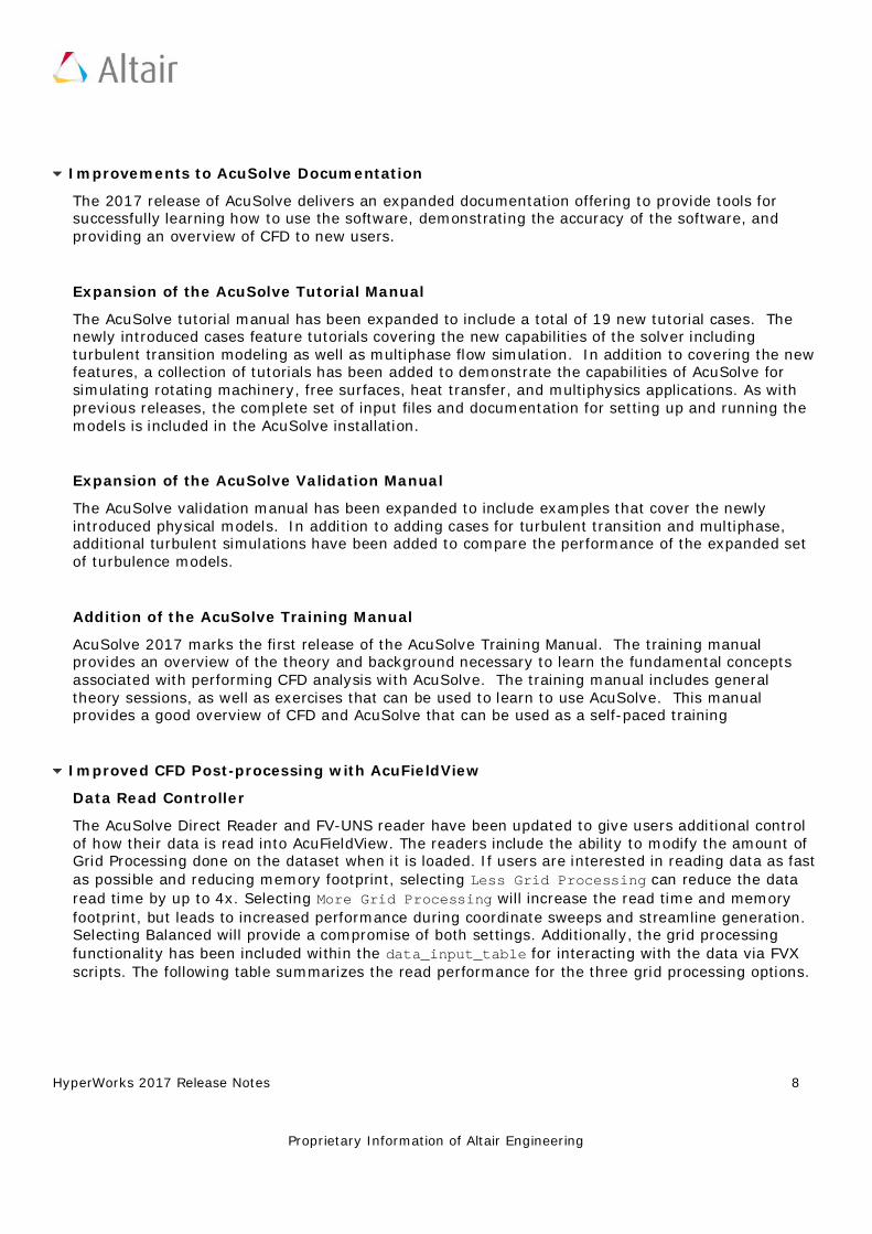
The AcuSolve Direct Reader and FV-UNS reader have been updated to give users additional control of how their data is read into AcuFieldView. The readers include the ability to modify the amount of Grid Processing done on the dataset when it is loaded. If users are interested in reading data as fast as possible and reducing memory footprint, selecting Less Grid Processing can reduce the data read time by up to 4x. Selecting More Grid Processing will increase the read time and memory footprint, but leads to increased performance during coordinate sweeps and streamline generation. Selecting Balanced will provide a compromise of both settings. Additionally, the grid processing functionality has been included within the data_input_table for interacting with the data via FVX scripts. The following table summarizes the read performance for the three grid processing options.
HyperWorks 2017 Release Notes 9
Proprietary Information of Altair Engineering
Read Time (sec) Grid Processing
Direct Reader
Model Node Count V14.0 Less Balanced More
CPU Fan 824145 78.1 16.9 27.1 71.9
Fuel Tank 660830 73.2 17.4 28.0 65.5
Industrial Fan 27435162 581.6 403.3 475.7 508.8
FV-UNS
Model Node Count V14.0 Less Balanced More
F1 Car 9119255 252.8 120.2 124.4 209.5
Golf Club 3588402 101.5 30.5 47.4 92.1
Performance of AcuSolve data read operations using AcuFieldView V14.0 and V2017
3D PDF Export
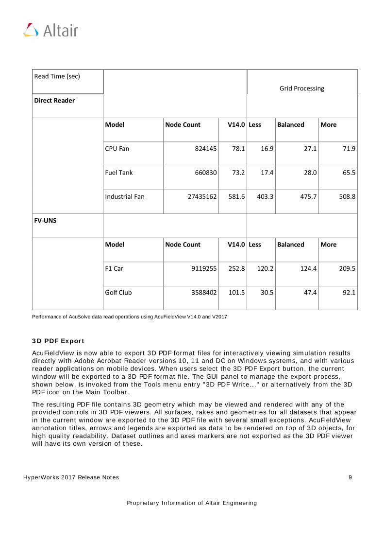
AcuFieldView is now able to export 3D PDF format files for interactively viewing simulation results directly with Adobe Acrobat Reader versions 10, 11 and DC on Windows systems, and with various reader applications on mobile devices. When users select the 3D PDF Export button, the current window will be exported to a 3D PDF format file. The GUI panel to manage the export process, shown below, is invoked from the Tools menu entry "3D PDF Write..." or alternatively from the 3D PDF icon on the Main Toolbar.
The resulting PDF file contains 3D geometry which may be viewed and rendered with any of the provided controls in 3D PDF viewers. All surfaces, rakes and geometries for all datasets that appear in the current window are exported to the 3D PDF file with several small exceptions. AcuFieldView annotation titles, arrows and legends are exported as data to be rendered on top of 3D objects, for high quality readability. Dataset outlines and axes markers are not exported as the 3D PDF viewer will have its own version of these.
HyperWorks 2017 Release Notes 10
Proprietary Information of Altair Engineering
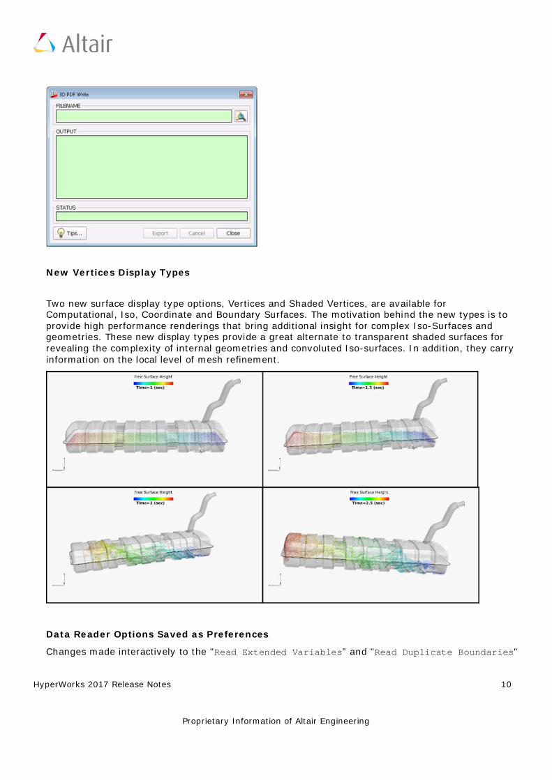
New Vertices Display Types
Two new surface display type options, Vertices and Shaded Vertices, are available for Computational, Iso, Coordinate and Boundary Surfaces. The motivation behind the new types is to provide high performance renderings that bring additional insight for complex Iso-Surfaces and geometries. These new display types provide a great alternate to transparent shaded surfaces for revealing the complexity of internal geometries and convoluted Iso-surfaces. In addition, they carry information on the local level of mesh refinement.
Data Reader Options Saved as Preferences
Changes made interactively to the "Read Extended Variables” and "Read Duplicate Boundaries"
HyperWorks 2017 Release Notes 11
Proprietary Information of Altair Engineering
control buttons on the AcuSolve Direct Reader panel are now retained within the AcuFieldView session and saved as preferences. This change allows AcuFieldView to remember these settings across all sessions run from the same machine. Saving the size and location of the main window, along with the location of the toolbars (and whether they are docked or not) is part of the broader functionality of saving preferences. This information is stored in FieldView.ini. Its location depends on the operating system where AcuFieldView is executed from.
Mid Step Mesh Displacement Support in Direct Reader
The AcuSolve Direct Reader now supports mid-step mesh displacement, using the following environment variable
FV_ACUSOLVE_PREFER_MIDSTEP
If this environment variable is set to any value prior to launching AcuFieldView, the reader looks for mid-step mesh displacement in the AcuSolve output database. If this is found, it is used to displace the mesh, and imported into the session as the mesh_displacement variable. The following message is printed to the console:
Displacing mesh coordinates using mid step mesh displacement field.
Other Notable Changes
AcuSolve 2017 contains a number of other notable changes that are worthy of mention. A brief description of each is shown below:
• Support for Intel compiler has been added to AcuMakeLib • Added higher order surface representation to GUIDE_SURFACE command to enable
smoothing of the discrete surface. • Added a check at inlet boundary conditions to protect against zero values of eddy viscosity
for Spalart-Allmaras based models. • Added sustaining terms to SST and k-epsilon based turbulence models to prevent decay of
turbulent energy in external flows. • Reduced the frequency at which the interface search is performed for sliding mesh
applications when the mesh stagger is solved multiple times consecutively. • AcuSub now truncates problem names according to the maximum length that is supported
by the scheduler. • Automatic initialization is now performed for Spalart-Allmaras based turbulence models
when zero initial conditions are detected. This change makes the behavior of Spalart-Allmaras consistent with the behavior of the 2-equation turbulence models under these circumstances.
• Improved the performance of AcuPev when operating on large models with a large number of eigen vectors.
• Added mixed topology surface and element set support to AcuTrace. • Added a check in AcuPrep to capture inlet values of eddy viscosity that are set to 0.0 for
turbulent simulations. • Reduced the frequency at which the interface search is performed for sliding mesh
applications that solve the mesh stagger multiple times per pass.
HyperWorks 2017 Release Notes 12
Proprietary Information of Altair Engineering
Notable Resolved Issues
• Resolved a crash in AcuPrep with models that contained large numbers of simple boundary conditions and surface outputs.
• Resolved a problem in AcuSolve when trying to restart from a simulation that contained a moving mesh and a solid element set.
• Resolved a problem in AcuSolve when using ELEMENT_OUTPUT in a simulation that contained a moving mesh and a solid element set.
• Corrected a problem with the satisfy_boundary_condition option of the NODAL_INITIAL_CONDITION command such that it does not apply to all variables in the simulation. Instead, it is applied only to the variable referenced in the current NODAL_INITIAL_CONDITION command.
• Resolved a problem with compression heating that led to incorrect results. • Fixed a bug associated with specifying anisotropic thermal conductivity through UDF. • Fixed a segmentation fault in AcuPrep when a SIMPLE_BOUNDARY_CONDITION command was
applied to an element set having medium=none. • Fixed a number of issues associated with special characters in the PATH variable on
Windows platforms. • Resolved an issue with AcuProj when projecting results from a mesh that contained prism
elements. • Resolved a segmentation fault in AcuPrep when encountering improperly formatted input. • Fixed a bug that impacted the behavior of ALE free surface mesh displacement when using
periodic boundary conditions. • Fixed a bug that caused spurious pressure and velocity fields on guide surfaces when using
match_mesh_velocity. • Fixed a bug in AcuTrans that led to invalid Ensight files. • Fixed a bug in AcuSolve that prevented the user specified Jacobian from being included in
the left hand side matrix when applying a surface heat flux element boundary condition through UDF.
• Fixed a bug in AcuSolve that caused incorrect results when specifying a nodal boundary condition for omega using a UDF
Changes to Supported Platforms and Third Party Packages
• Removed mx-mpi and gm-mpi entirely from installation packages and discontinued support • Updated Intel MPI to version V5.1.3.223 on Linux and V5.1.3.180 on Windows • Updated MPICH to v3.2 on Linux
HyperWorks 2017 Release Notes 13
Proprietary Information of Altair Engineering
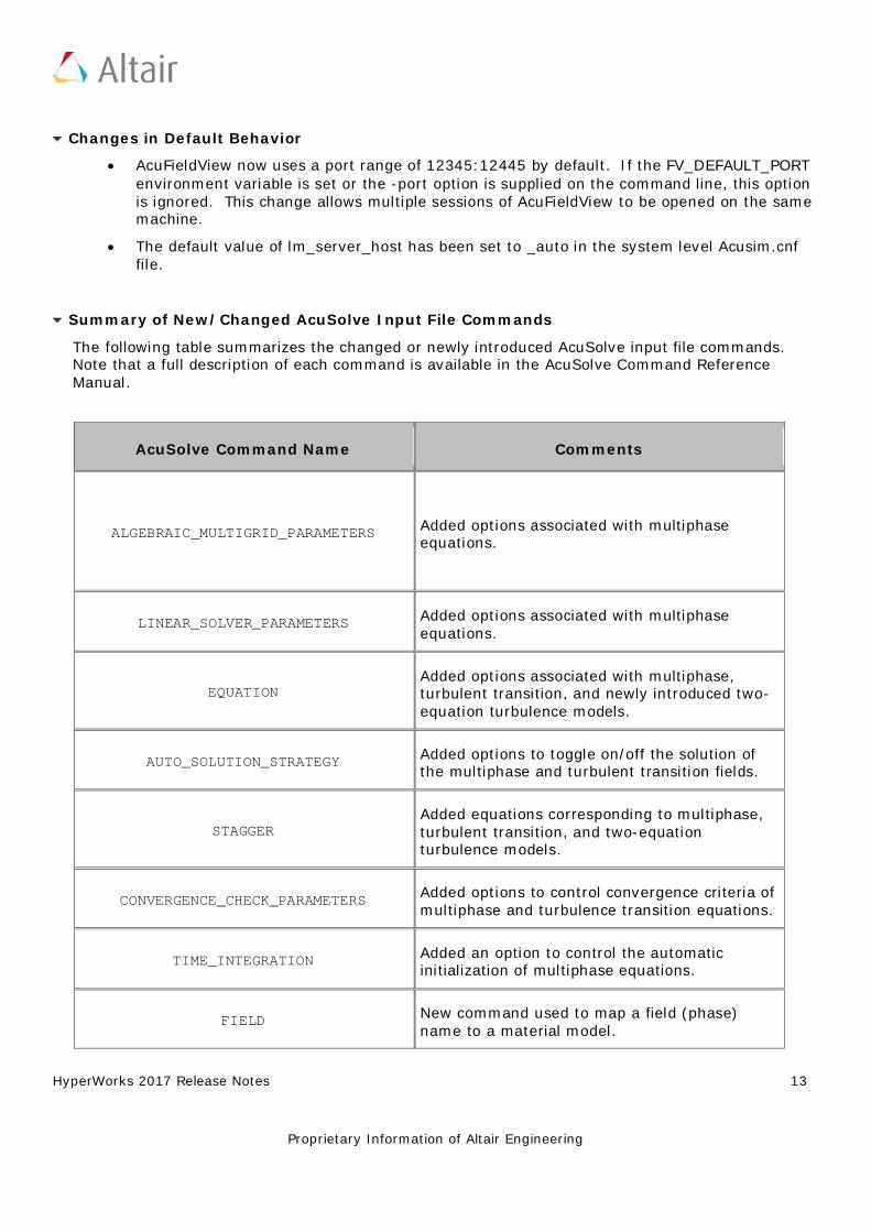
Changes in Default Behavior
• AcuFieldView now uses a port range of 12345:12445 by default. If the FV_DEFAULT_PORT environment variable is set or the -port option is supplied on the command line, this option is ignored. This change allows multiple sessions of AcuFieldView to be opened on the same machine.
• The default value of lm_server_host has been set to _auto in the system level Acusim.cnf file.
Summary of New/Changed AcuSolve Input File Commands
The following table summarizes the changed or newly introduced AcuSolve input file commands. Note that a full description of each command is available in the AcuSolve Command Reference Manual.
AcuSolve Command Name Comments
ALGEBRAIC_MULTIGRID_PARAMETERS Added options associated with multiphase equations.
LINEAR_SOLVER_PARAMETERS Added options associated with multiphase equations.
EQUATION Added options associated with multiphase, turbulent transition, and newly introduced two-equation turbulence models.
AUTO_SOLUTION_STRATEGY Added options to toggle on/off the solution of the multiphase and turbulent transition fields.
STAGGER Added equations corresponding to multiphase, turbulent transition, and two-equation turbulence models.
CONVERGENCE_CHECK_PARAMETERS Added options to control convergence criteria of multiphase and turbulence transition equations.
TIME_INTEGRATION Added an option to control the automatic initialization of multiphase equations.
FIELD New command used to map a field (phase) name to a material model.
HyperWorks 2017 Release Notes 14
Proprietary Information of Altair Engineering
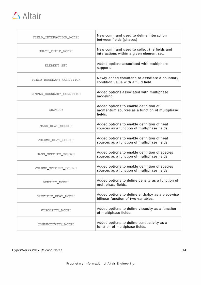
FIELD_INTERACTION_MODEL New command used to define interaction between fields (phases)
MULTI_FIELD_MODEL New command used to collect the fields and interactions within a given element set.
ELEMENT_SET Added options associated with multiphase support.
FIELD_BOUNDARY_CONDITION Newly added command to associate a boundary condition value with a fluid field.
SIMPLE_BOUNDARY_CONDITION Added options associated with multiphase modeling.
GRAVITY Added options to enable definition of momentum sources as a function of multiphase fields.
MASS_HEAT_SOURCE Added options to enable definition of heat sources as a function of multiphase fields.
VOLUME_HEAT_SOURCE Added options to enable definition of heat sources as a function of multiphase fields.
MASS_SPECIES_SOURCE Added options to enable definition of species sources as a function of multiphase fields.
VOLUME_SPECIES_SOURCE Added options to enable definition of species sources as a function of multiphase fields.
DENSITY_MODEL Added options to define density as a function of multiphase fields.
SPECIFIC_HEAT_MODEL Added options to define enthalpy as a piecewise bilinear function of two variables.
VISCOSITY_MODEL Added options to define viscosity as a function of multiphase fields.
CONDUCTIVITY_MODEL Added options to define conductivity as a function of multiphase fields.
HyperWorks 2017 Release Notes 15
Proprietary Information of Altair Engineering
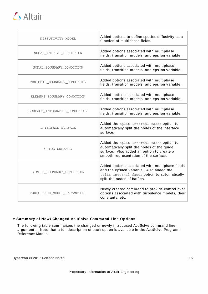
DIFFUSIVITY_MODEL Added options to define species diffusivity as a function of multiphase fields.
NODAL_INITIAL_CONDITION Added options associated with multiphase fields, transition models, and epsilon variable.
NODAL_BOUNDARY_CONDITION Added options associated with multiphase fields, transition models, and epsilon variable.
PERIODIC_BOUNDARY_CONDITION Added options associated with multiphase fields, transition models, and epsilon variable.
ELEMENT_BOUNDARY_CONDTIION Added options associated with multiphase fields, transition models, and epsilon variable.
SURFACE_INTEGRATED_CONDITION Added options associated with multiphase fields, transition models, and epsilon variable.
INTERFACE_SURFACE Added the split_internal_faces option to automatically split the nodes of the interface surface.
GUIDE_SURFACE
Added the split_internal_faces option to automatically split the nodes of the guide surface. Also added an option to create a smooth representation of the surface.
SIMPLE_BOUNDARY_CONDITION
Added options associated with multiphase fields and the epsilon variable. Also added the split_internal_faces option to automatically split the nodes of baffles.
TURBULENCE_MODEL_PARAMETERS Newly created command to provide control over options associated with turbulence models, their constants, etc.
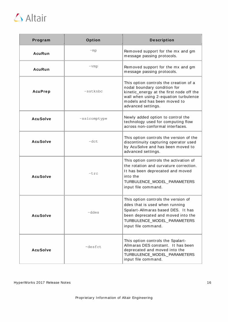
Summary of New/Changed AcuSolve Command Line Options
The following table summarizes the changed or newly introduced AcuSolve command line arguments. Note that a full description of each option is available in the AcuSolve Programs Reference Manual.
HyperWorks 2017 Release Notes 16
Proprietary Information of Altair Engineering
Program Option Description
AcuRun -mp Removed support for the mx and gm
message passing protocols.
AcuRun -vmp Removed support for the mx and gm
message passing protocols.
AcuPrep -sstknbc
This option controls the creation of a nodal boundary condition for kinetic_energy at the first node off the wall when using 2-equation turbulence models and has been moved to advanced settings.
AcuSolve -ssicomptype Newly added option to control the technology used for computing flow across non-conformal interfaces.
AcuSolve -dct This option controls the version of the discontinuity capturing operator used by AcuSolve and has been moved to advanced settings.
AcuSolve -trc
This option controls the activation of the rotation and curvature correction. It has been deprecated and moved into the TURBULENCE_MODEL_PARAMETERS input file command.
AcuSolve -ddes
This option controls the version of ddes that is used when running Spalart-Allmaras based DES. It has been deprecated and moved into the TURBULENCE_MODEL_PARAMETERS input file command.
AcuSolve -desfct
This option controls the Spalart-Allmaras DES constant. It has been deprecated and moved into the TURBULENCE_MODEL_PARAMETERS input file command.
HyperWorks 2017 Release Notes 17
Proprietary Information of Altair Engineering
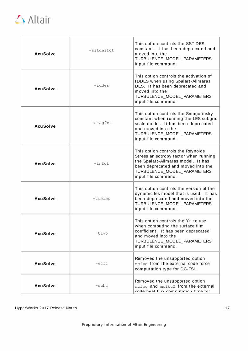
AcuSolve -sstdesfct
This option controls the SST DES constant. It has been deprecated and moved into the TURBULENCE_MODEL_PARAMETERS input file command.
AcuSolve -iddes
This option controls the activation of IDDES when using Spalart-Allmaras DES. It has been deprecated and moved into the TURBULENCE_MODEL_PARAMETERS input file command.
AcuSolve -smagfct
This option controls the Smagorinsky constant when running the LES subgrid scale model. It has been deprecated and moved into the TURBULENCE_MODEL_PARAMETERS input file command.
AcuSolve -tnfct
This option controls the Reynolds Stress anisotropy factor when running the Spalart-Allmaras model. It has been deprecated and moved into the TURBULENCE_MODEL_PARAMETERS input file command.
AcuSolve -tdmimp
This option controls the version of the dynamic les model that is used. It has been deprecated and moved into the TURBULENCE_MODEL_PARAMETERS input file command.
AcuSolve -tlyp
This option controls the Y+ to use when computing the surface film coefficient. It has been deprecated and moved into the TURBULENCE_MODEL_PARAMETERS input file command.
AcuSolve -ecft Removed the unsupported option mcibc from the external code force computation type for DC-FSI.
AcuSolve -echt Removed the unsupported option mcibc and mcibc2 from the external code heat flux computation type for
HyperWorks 2017 Release Notes 18
Proprietary Information of Altair Engineering
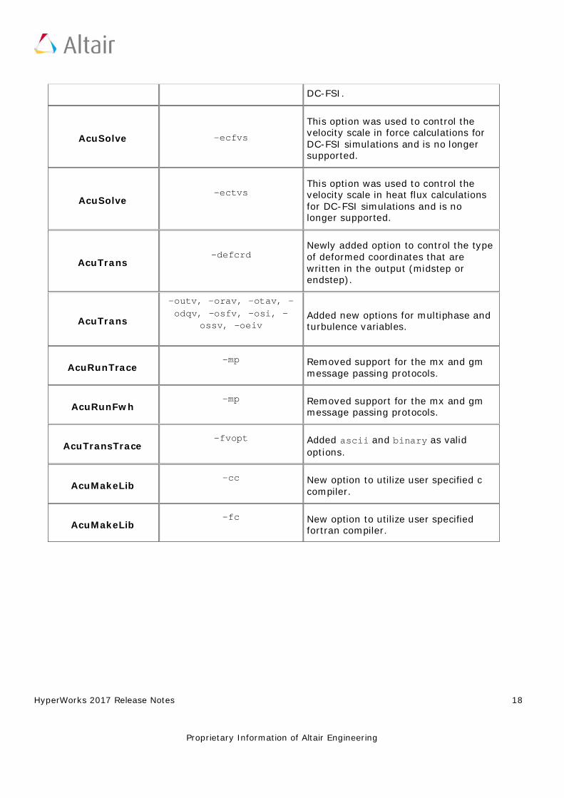
DC-FSI.
AcuSolve -ecfvs
This option was used to control the velocity scale in force calculations for DC-FSI simulations and is no longer supported.
AcuSolve -ectvs
This option was used to control the velocity scale in heat flux calculations for DC-FSI simulations and is no longer supported.
AcuTrans -defcrd
Newly added option to control the type of deformed coordinates that are written in the output (midstep or endstep).
AcuTrans
-outv, -orav, -otav, -odqv, -osfv, -osi, -
ossv, -oeiv Added new options for multiphase and turbulence variables.
AcuRunTrace -mp Removed support for the mx and gm
message passing protocols.
AcuRunFwh -mp Removed support for the mx and gm
message passing protocols.
AcuTransTrace -fvopt Added ascii and binary as valid
options.
AcuMakeLib -cc New option to utilize user specified c
compiler.
AcuMakeLib -fc New option to utilize user specified
fortran compiler.

HyperWorks 2017 Release Notes 19
Proprietary Information of Altair Engineering
FEKO
Altair® FEKO® is a comprehensive computational electromagnetics (CEM) software used widely in the telecommunications, automobile, aerospace and defence industries.
FEKO offers several frequency and time domain electromagnetic (EM) solvers under a single license. Hybridisation of these methods enables the efficient solution of a broad spectrum of EM problems including analyses of antennas, microstrip circuits, RF components and biomedical systems, placement of antennas on electrically large structures, calculating scattering effects and performing electromagnetic compatibility (EMC) studies.
Highlights
The FEKO 2017 release is packed with features and improvements to create a platform for simulation-driven innovation. Since the 14.0 release, features have been made available to users in quarterly updates allowing users to take advantage of the extended capabilities as soon as they are ready. The most notable extensions in this release are:
Computational Performance Improvements
• The finite difference time domain (FDTD) solver supports OpenMP and MPI parallelisation allowing users to take full advantage of machines with multiple cores and multiple computation nodes in cluster environments.
• The ray launching geometrical optics (RL-GO) solver has been improved considerably in terms of speed and resource efficiency (memory reduction). Innovative algorithms select the most suitable ray distribution and automatically determine when enough ray interactions have been taken into account.
HyperWorks 2017 Release Notes 20
Proprietary Information of Altair Engineering
Extensions to the EM Solver Expands the Portfolio of Physics that can be Solved
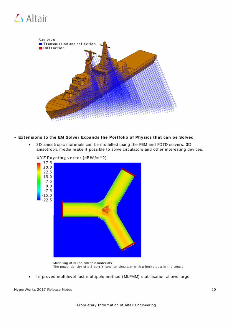
• 3D anisotropic materials can be modelled using the FEM and FDTD solvers. 3D anisotropic media make it possible to solve circulators and other interesting devices.
Modelling of 3D anisotropic materials: The power density of a 3-port Y-junction circulator with a ferrite post in the centre.
• Improved multilevel fast multipole method (MLFMM) stabilisation allows large
HyperWorks 2017 Release Notes 21
Proprietary Information of Altair Engineering
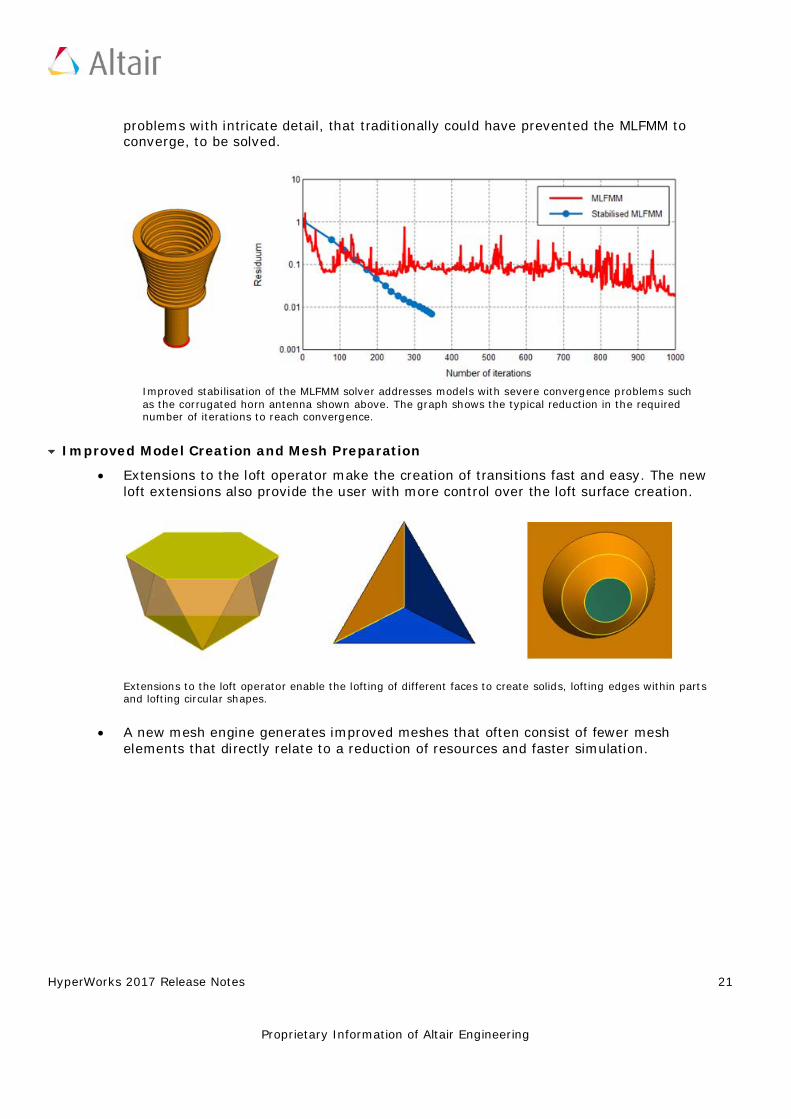
problems with intricate detail, that traditionally could have prevented the MLFMM to converge, to be solved.
Improved stabilisation of the MLFMM solver addresses models with severe convergence problems such as the corrugated horn antenna shown above. The graph shows the typical reduction in the required number of iterations to reach convergence.
Improved Model Creation and Mesh Preparation
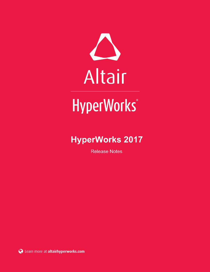
• Extensions to the loft operator make the creation of transitions fast and easy. The new loft extensions also provide the user with more control over the loft surface creation.
Extensions to the loft operator enable the lofting of different faces to create solids, lofting edges within parts and lofting circular shapes.
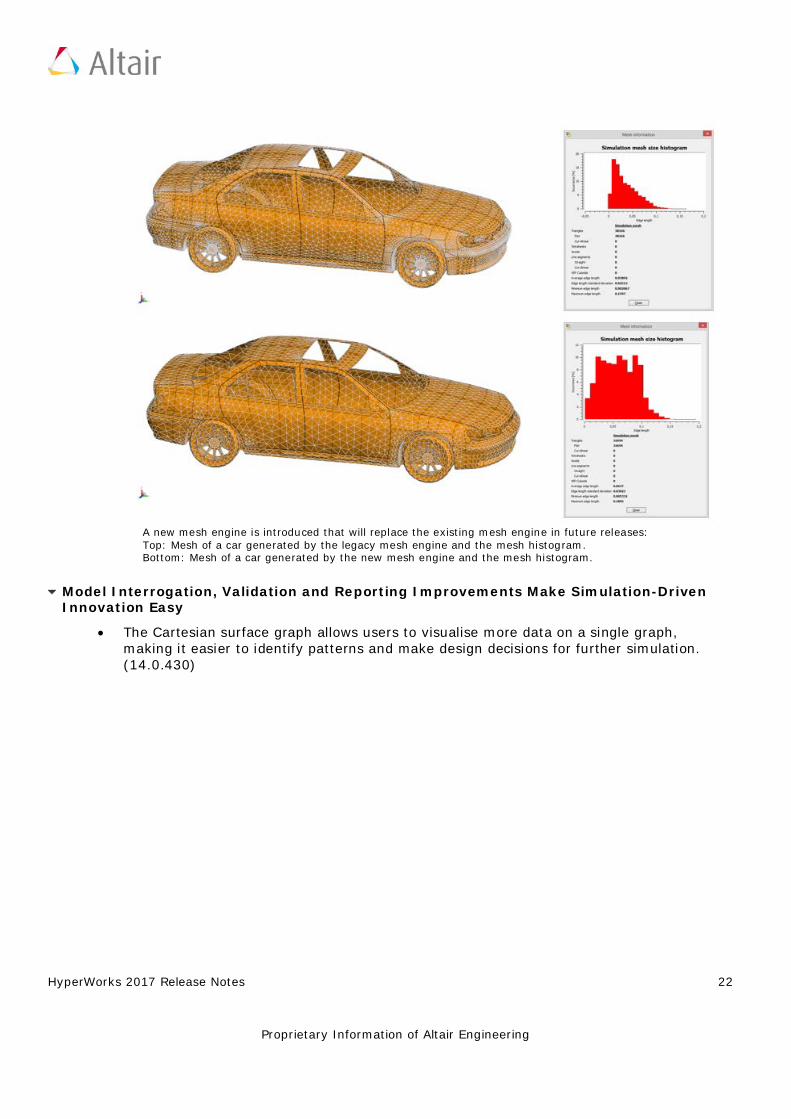
• A new mesh engine generates improved meshes that often consist of fewer mesh elements that directly relate to a reduction of resources and faster simulation.
HyperWorks 2017 Release Notes 22
Proprietary Information of Altair Engineering
A new mesh engine is introduced that will replace the existing mesh engine in future releases: Top: Mesh of a car generated by the legacy mesh engine and the mesh histogram. Bottom: Mesh of a car generated by the new mesh engine and the mesh histogram.
Model Interrogation, Validation and Reporting Improvements Make Simulation-Driven Innovation Easy
• The Cartesian surface graph allows users to visualise more data on a single graph, making it easier to identify patterns and make design decisions for further simulation. (14.0.430)
HyperWorks 2017 Release Notes 23
Proprietary Information of Altair Engineering
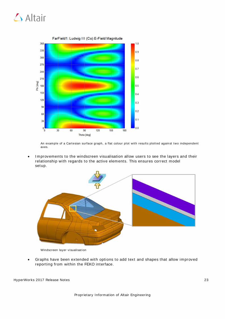
An example of a Cartesian surface graph, a flat colour plot with results plotted against two independent axes.
• Improvements to the windscreen visualisation allow users to see the layers and their relationship with regards to the active elements. This ensures correct model setup.
Windscreen layer visualisation
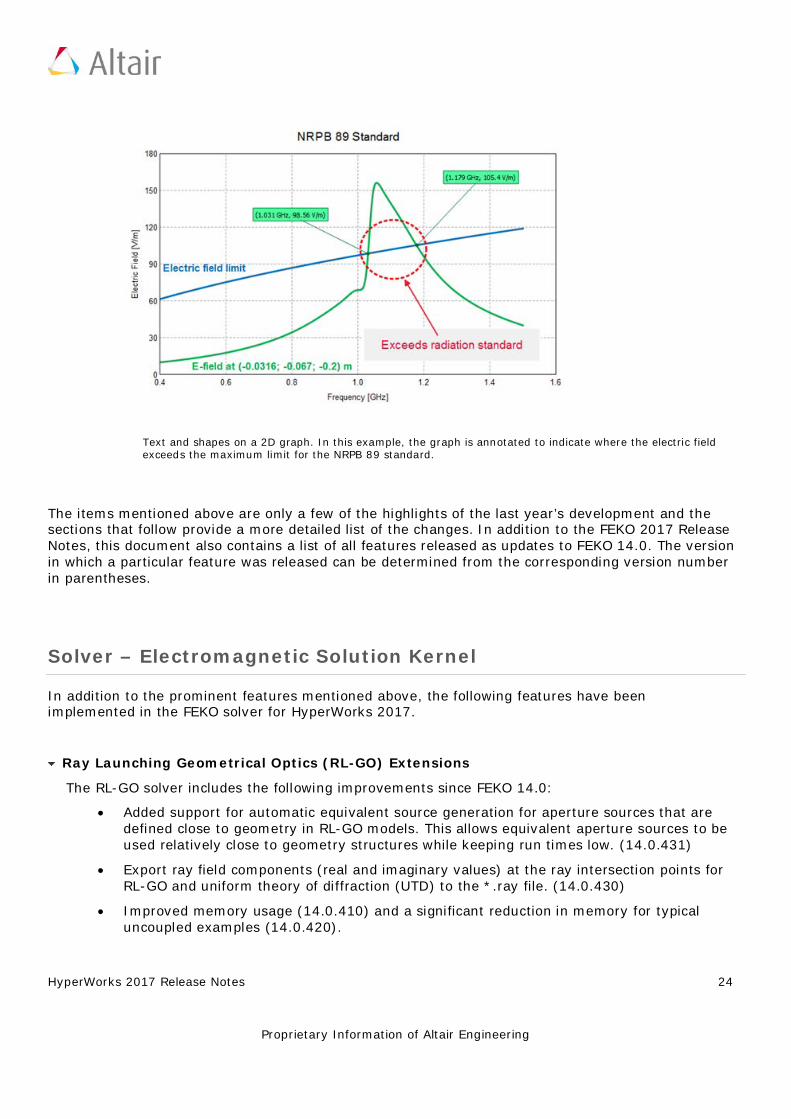
• Graphs have been extended with options to add text and shapes that allow improved reporting from within the FEKO interface.
HyperWorks 2017 Release Notes 24
Proprietary Information of Altair Engineering
Text and shapes on a 2D graph. In this example, the graph is annotated to indicate where the electric field exceeds the maximum limit for the NRPB 89 standard.
The items mentioned above are only a few of the highlights of the last year’s development and the sections that follow provide a more detailed list of the changes. In addition to the FEKO 2017 Release Notes, this document also contains a list of all features released as updates to FEKO 14.0. The version in which a particular feature was released can be determined from the corresponding version number in parentheses.
Solver – Electromagnetic Solution Kernel
In addition to the prominent features mentioned above, the following features have been implemented in the FEKO solver for HyperWorks 2017.
Ray Launching Geometrical Optics (RL-GO) Extensions
The RL-GO solver includes the following improvements since FEKO 14.0:
• Added support for automatic equivalent source generation for aperture sources that are defined close to geometry in RL-GO models. This allows equivalent aperture sources to be used relatively close to geometry structures while keeping run times low. (14.0.431)
• Export ray field components (real and imaginary values) at the ray intersection points for RL-GO and uniform theory of diffraction (UTD) to the *.ray file. (14.0.430)
• Improved memory usage (14.0.410) and a significant reduction in memory for typical uncoupled examples (14.0.420).
HyperWorks 2017 Release Notes 25
Proprietary Information of Altair Engineering
• The algorithms used to select the initial ray launching increment are extended to increase accuracy in many cases. The improved automatic selection settings often result in increased performance. (14.0.410)
• Improved RL-GO accuracy for certain model configurations. (14.0.410) • Improved geometry checks for curvilinear triangles prevent possible numerical errors for
curvilinear RL-GO models. (14.0.431) • The run time is reported for equivalent source transformations. (2017)
Resolved RL-GO issues:
• Allow more subdivisions for the equivalent source generation for RL-GO to improve run time. (2017)
• Check that elements solved using the method of moments (MoM) do not touch elements solved using the RL-GO method. (2017)
• Fixed a bug that caused RL-GO rays to pass through geometry in rare circumstances when using incident fields in multiple directions, multiple frequencies loops or multiple configurations. (2017)
• Resolved an issue that caused FEKO to stop with an undefined error for certain RL-GO models that consume a lot of memory. (14.0.431)
• Resolved an issue that caused RL-GO and PO examples with high loss dielectric sheets or coatings to be computed incorrectly. (14.0.431)
• Resolved an issue that caused very poor memory usage for some RL-GO models that requested far fields. (14.0.431)
• Resolved an issue that caused a slowdown for RL-GO models where a large number of far field request points were used. (14.0.430)
• Corrected a check for the applicability of the RL-GO for media with high losses. (14.0.430) • Resolved various internal error states for specific RL-GO cases. Resolved RL-GO errors
include those given when using certain sources, when using certain sources together with planar multilayer structures, when spherical modes are requested and when the model contains a plane wave source and a receiving antenna. (14.0.421)
• Resolved an issue that could have caused incorrect results to be computed when trying to read a corrupt cache file using RL-GO. (14.0.421)
• Improved RL-GO performance when no near field or far field requests are present in the model. (14.0.421)
• Added support for default incident sources when none are specified for monostatic RCS requests solved with RL-GO. (14.0.421)
• Corrected problems with exporting rays to file when using RL-GO. (14.0.411) • Resolved various internal error states for specific RL-GO problems. In some models the
error state was given when using high accuracy mode and in others when requesting the radar cross section. (14.0.401)
HyperWorks 2017 Release Notes 26
Proprietary Information of Altair Engineering
Finite Difference Time Domain (FDTD) Extensions
The most prominent extension is the support of OpenMP and MPI parallelisation for the FDTD solver. (2017)
Other extensions to the FDTD solver include:
• Support of biaxial anisotropic media for the FDTD. (2017) • Support of RLC loads for the FDTD method. In the past for the FDTD only a single discrete
resistance, inductance or capacitance was supported per port. (2017) • Support for voltage/other sources together with plane wave excitation in the FDTD solver.
(14.0.420)
Resolved FDTD issues:
• Resolved a segmentation violation given when multiple plane wave sources are used for an FDTD model. (2017)
• Resolved an issue that caused incorrect results for transverse H-fields on FDTD boundaries (PEC and PMC). (14.0.421)
• Resolved issues that caused incorrect results close to perfect magnetic (PMC) boundaries when using the FDTD. (14.0.411, 14.0.420)
• Resolved an issue that could have caused an internal FEKO error when using empty ports with the FDTD. (14.0.411)
• Changed the phase reference for far fields calculated using the FDTD to be in agreement with the reference used by other supported methods. (14.0.401)
• Improved FDTD pre-processing speed. (14.0.401) • Improved stability of small field value variation for the FDTD. (14.0.401) • Resolved an error state given for certain FDTD port configurations. (14.0.401) • Improved memory usage for the FDTD when using a GPU. (14.0.411) • Resolved an internal error state given for certain FDTD models when solved using a GPU.
(14.0.401)
Finite Element Method (FEM) Extensions
The FEM solver changes include:
• Support parallel and series RLC loads for the FEM line port. In the past, only complex impedances were supported. (2017)
• Support anisotropic materials for the FEM. This allows non-reciprocal ferrite materials to be modelled with the FEM. (2017)
• Added support to re-use the LU-decomposition (when possible) for models where the FEM/MoM method is used. (14.0.410)
• Improved the pre-processing speed for certain FEM models. (14.0.410) • Resolved an issue that caused an internal error state for certain FEM models computed in
HyperWorks 2017 Release Notes 27
Proprietary Information of Altair Engineering
parallel. (14.0.430) • Resolved an issue that could have caused incorrect results for FEM models with rotationally
symmetric modal ports. (14.0.421)
Resolved FEM issues:
• Resolved an issue with incorrectly impressed FEM modal port eigenmodes on the general 3D FEM mesh in certain instances. (2017)
• Only give an error stating that active materials are not supported when these defined materials are used in the model. (14.0.431)
• Resolved an issue that could cause geometry checking to fail for certain FEM models. (14.0.411)
• Resolved an issue that could have led to an internal FEKO error for FEM-only examples. (14.0.410)
• Fixed a bug that prevented a non-perfect electric conductor (non-PEC) from being used in FEM modal ports. (14.0.401)
Characteristic Mode Analysis (CMA) Extensions
CMA changes include:
• Improved accuracy and stability of higher order characteristic mode computation. (14.0.430)
• Improved the speed of tracking degenerate characteristic modes. (14.0.430) • Improved the characteristic mode tracking algorithms. (14.0.410)
Cable Analysis Extensions
Cable changes include:
• Speed improvements for certain cable modelling scenarios. (14.0.420) • Cable harnesses now allow loading with 1-port Touchstone files. (14.0.420)
Resolved cable issues:
• Resolved an internal error state that occurred for nearly parallel cable paths. (14.0.431) • General improvements to multiconductor transmission line (MTL) cable modelling that
should result in more accurate results for certain sensitive models. (14.0.401) • Resolved an issue that caused an error to be raised for certain MoM/MTL models where
different paths are physically connected. (14.0.431) • Resolved an issue that caused an internal error state for certain multiple configuration cable
examples. (14.0.430)
HyperWorks 2017 Release Notes 28
Proprietary Information of Altair Engineering
• Resolved an issue that caused an internal error state for cable models where component values tend to be close to internal thresholds of the SPICE circuit solver. (14.0.430)
• Improved performance for cables. (14.0.421) • Significantly reduced solution time when using the default SPICE solver. (14.0.420) • Fixed a bug that caused and error state for certain cable models during the Delaunay
triangulation phase. (14.0.401) • Fixed a bug that caused in an internal error state for certain cable problems that have
intersecting cables. (14.0.401) • Fixed a bug that might cause incorrect results when using multiple cable configurations with
irradiating multiple transmission line solutions. (14.0.401)
Upgrade of Third-Party Libraries
• Upgrade to Intel MPI Library 5.1 Update 3. (2017) • Upgrade to MPICH 3.2 for Linux systems. (2017) • Upgrade to SuperLU 5.2.1 (May 22, 2016), a sparse matrix solver not used as the default
solver. (2017) • Upgrade to SuperLU_DIST 5.1.0 (May 15, 2016), a sparse parallel matrix solver not used as
the default solver. (2017) • Upgrades of various parallel libraries and compilers to improve the general stability of
iterative processes when run in parallel. (14.0.401) • Updated an external library that may improve memory usage for certain parallel sparse
methods (FEM, MLFMM). (14.0.401)
General Extensions
• Improved memory estimation and reporting for the fast far field calculation. (2017) • Included the global response surface method (GRSM) and adaptive response surface
method (ARSM) as new optimisation methods. These methods internally build a response surface that updates as more sample points are added. The ARSM terminates when one of the convergence criteria is met, while the GRSM continues to test different areas of the design space. (14.0.430)
• Added support to import near field scan data (*.NFS) with irregular grid spacing as source data in FEKO. (14.0.430)
• The domain Green's function method (used for array modelling) now supports dielectric media modelled using surface equivalence. (14.0.430)
• Support for importing electric and/or magnetic near fields on all faces of a cuboid simultaneously from an *.efe/*.hfe file. (14.0.421)
• SAR can now be calculated for non-magnetic materials, even when the model contains magnetic materials. (14.0.421)
• Added the option to allow additional stabilisation for the MLFMM to address models with
HyperWorks 2017 Release Notes 29
Proprietary Information of Altair Engineering
severe convergence problems. (14.0.420) • Support was added for near field potential requests when using the MLFMM. (14.0.410) • Always compute the near field when using the MLFMM even in the presence of an infinite
PEC ground plate. (14.0.401) • Increased the applicable models for which source optimisations are done. (14.0.420) • Reduced the required separation distance for aperture equivalent sources. (14.0.420) • Support for curvilinear wires as part of windscreen antennas. (14.0.420) • Speed improvements when using aperture sources. (14.0.410) • Support for scalar potentials was added for planar Green’s function solutions. (14.0.410) • The medium reported for near field requests when using VEP elements is now based on the
medium at the observation point. (14.0.410) • Support was added to ensure that the required amount of hard disk space is available when
writing out large intermediate solution files (*.mat/*.lud/*.ngf). (14.0.420) • Support negative angles when importing far fields using *.ffe files. (14.0.401) • Support for importing I-DEAS universal format mesh files is added (14.0.410) and extended
to read wire radius values. (14.0.411) • Configuration names are now written to exported field request files (*.ffe, *.efe, *.hfe,
*.os, *.ol). (14.0.410)
General Resolved Issues
• Fixed a bug that caused the LU-decomposition to fail for certain MoM type problems where many frequencies are requested. (2017)
• Fixed a race condition that sometimes caused an error when writing UTD rays to disk for some parallel jobs. (2017)
• Fixed a bug that incorrectly extended numerical Green's function (NGF) files when changes are made to the model or solution parameters such as frequency. (2017)
• Resolved an issue that could have caused incorrect results to be calculated when using the numerical Green's function (NGF) for certain models. (14.0.411)
• Fixed a bug that caused an internal error state when using the NGF together with the FEM in parallel. (14.0.401)
• The restriction that the relative permeability and magnetic loss tangent should stay constant for thin isotropic dielectric sheets is removed for the high frequency techniques (RL-GO, PO and UTD). (14.0.431)
• Resolved an issue that caused an error when importing a stored matrix file when using multiple configurations in a parallel execution environment. (14.0.431)
• Resolved an issue that caused an internal error state for certain MLFMM models that use the SPAI preconditioner in parallel. (14.0.431)
• Fixed a bug that caused an internal error state when using MLFMM together with certain near field sources. (14.0.401)
HyperWorks 2017 Release Notes 30
Proprietary Information of Altair Engineering
• Improved error handling for certain parallel sparse linear reordering algorithms (used by MLFMM) when the model is of a multi-scale nature. (14.0.401)
• Consistently calculate losses at wire-triangle junctions to ensure the reported radiation efficiency is always positive. (14.0.431)
• Resolved an issue with loads specified by node position and spherical mode receiving antennas where scaling was not as expected when using an SF card. (14.0.431)
• Resolved an issue where incorrect reflections were calculated for magnetic thin dielectric sheets and coatings when solved with physical optics (PO), UTD, or RL-GO. This involves models containing sheets or coatings where any layer has a relative permeability larger than 1. MoM and MLFMM solutions for these models are not affected by this bug and remain correct. (14.0.430)
• Removed the option to calculate radar cross section (RCS) in a different reference frame than the incident source. (14.0.430)
• Improved handling of certain complex spherical mode sources that are close to geometry. (14.0.430)
• Resolved an issue that prevented certain examples from being solved in parallel when using MPICH (not the default) with the Windows operating system. (14.0.430)
• Resolved an issue that caused an internal error state for certain examples that use multiple aperture sources. (14.0.430)
• Resolved an issue that caused an internal error state for double negative materials (DNG). (14.0.430)
• Resolved an issue where an error was raised for certain edge port S-parameter models. (14.0.430)
• Improved the accuracy of windscreen geometry checking. (14.0.430) • Increased the number of digits displayed for simulation run time. The times for longer runs
are now displayed, instead of the asterisks that are printed out in case of an overflow. (14.0.430)
• Added a check to disallow MoM wire connections to large element physical optics (LE-PO) triangles. (14.0.430)
• Added a check to disallow wire segments from being located inside a periodic boundary. (14.0.430)
• Resolved an issue that caused runfeko to hang if the license file is not available. (2017) • It is ensured in RUNFEKO that parallel FEKO runs on Linux internally use the bash shell
instead of another default shell the user might have set up. (14.0.430) • Resolved an issue where importing material parameters into CADFEKO using an XML-file
resulted in an error. (14.0.421) • Resolved an issue that caused an error when importing a stored matrix file using multiple
configurations in a parallel execution environment. (14.0.421) • Improved accuracy for near field calculations using PO. (14.0.421) • Improved cross-coupling accuracy for wires above infinite high conductivity layers.
HyperWorks 2017 Release Notes 31
Proprietary Information of Altair Engineering
(14.0.421) • Resolved an issue that could have caused incorrect results for projects with multiple
configurations when using network port sources. (14.0.421) • Improved parallel scaling for far field calculation using UTD projects. (14.0.421) • Inform users when current requests are not supported and that no currents will be
exported. (14.0.421) • Improved far field parallelisation for certain model configurations. (14.0.420) • Resolved an issue that could potentially cause an error state for certain PO models.
(14.0.411) • Resolved an issue that could cause incorrect results when using higher order basis functions
(HOBF) in conjunction with the MoM when the model is run out-of-core. (14.0.411) • Resolved an issue that could cause inaccurate results when using the MoM in a model
containing curvilinear as well as flat elements. (14.0.411) • Resolved an issue that prevented FEKO from running using MPI ABI compatibility on certain
native MPI implementations. (14.0.411) • Improved the power loss calculation for periodic boundary condition (PBC) structures.
(14.0.411) • Resolved an issue where the stored matrix was not read in certain circumstances.
(14.0.411) • Resolved an issue that could have caused an internal FEKO error for certain current
requests. (14.0.411) • Resolved an issue that could have caused incorrectly orientated far fields and request
combinations. (14.0.411) • Improved the handling of components using spherical modes (for example receiving
antennas) to allow closer distances between objects. (14.0.411) • Resolved an issue that the names of near field objects could be imported incorrectly from
*.nfs file. (14.0.410) • Resolved an issue that could have led to incorrect data when requesting the scalar potential
gradient. (14.0.410) • Resolved an issue that could have led to incorrect data for the magnetic frill excitation when
power scaling is applied. (14.0.410) • Resolved an issue that could have led to incorrect data when using finite arrays in
conjunction with waveguide ports or microstrip ports in specific model configurations. (14.0.410)
• Resolved an issue that could have led to high memory usage and an internal FEKO error for spherical mode examples. (14.0.410)
• Improved checks for source optimisation in the vicinity of geometry. (14.0.410) • Improved curvilinear element support. (14.0.410) • Resolved an issue with PREFEKO that could have led to an error state when importing
Sigrity near field data (NFD) files. (14.0.410)
HyperWorks 2017 Release Notes 32
Proprietary Information of Altair Engineering
• Fixed a bug that resulted in incorrect power calculation when using multiple dipoles with specific near field requests. (14.0.401)
• Improved the robustness of geometry checking phases. (14.0.401) • Fixed a bug that might cause an incorrect error condition when checking combined field
integral equation (CFIE) geometry consistency. (14.0.401) • Fixed a bug that caused certain processes to be repeated between different configurations
when changing radiating sources in problems that contain networks. (14.0.401) • Fixed a bug that caused incorrect results for certain periodic boundary problems where the
total problem size is large. (14.0.401) • Improved the algorithm that chooses between standard and fast far field calculations.
(14.0.401) • Fixed a bug that could lead to incorrect results when using far field point sources in certain
circumstances. (14.0.401) • Fixed a bug that prohibited source information from being written to the text output file in
certain instances. (14.0.401) • Support negative angles when importing far fields using *.ffe files. (14.0.401) • Fixed an internal error state that was caused when running certain models using PO in
parallel. (14.0.401) • Multilayer electrically thin coatings are now supported for the MoM. (14.0.401) • Fixed a bug that caused output files to be deleted when they are larger than 2 GByte in
size. (14.0.401) • Fixed a bug that caused certain intermediate files to be deleted incorrectly when multiple
jobs run on the same system. (14.0.401) • Fixed a bug that caused OPTFEKO to incorrectly farm jobs on a local machine. (14.0.401)
CADFEKO – 3D CAD Modeler
CADFEKO, the 3D CAD modeller, has been extended to support all new features and solution techniques in the FEKO solver. In addition to supporting the new solver features, numerous other features and improvements have also been implemented. These features are listed in the sections that follow.
New Mesh Engine (2017)
FEKO 2017 includes a new default mesher. The new mesh engine generates improved meshes that often consist of fewer mesh elements that directly relate to a reduction of resources and faster simulation. The mesh engine from previous versions is still included in FEKO 2017 and users can switch between the two mesh engines. In future releases, the new mesh engine will replace the legacy mesh engine.
HyperWorks 2017 Release Notes 33
Proprietary Information of Altair Engineering
3D Anisotropic Materials (2017)
Anisotropic media (3D) are supported and can be applied to regions when using the finite element method (FEM) or finite difference time domain (FDTD) solver. An anisotropic medium is described by using one of the following methods: full tensor, diagonalised tensor, complex tensor or Polder tensor (ferrites). The FEM solver supports anisotropic media defined in a local coordinate system. The FDTD solver currently supports only anisotropic media defined in the global X, Y and Z coordinate system.
Loft Operator Extensions (2017)
• Lofting of the following is possible: − Lofting faces and surfaces to create solid shapes. − Lofting closed curves, such as closed elliptic arcs and closed polylines. − Lofting profiles containing different numbers of vertices. − Lofting faces or edges/wires within parts. These faces or edges/wires are copied out of the
original part into the loft. • Twists can be added or removed from closed lofts by specifying the alignment between
profiles. • The loft preview in the 3D view displays numbered indices, with improved indication of valid
and invalid lofts. • The CADFEKO API includes new methods for lofting edges (and/or wires), lofting faces and
lofting geometry using a table defining the loft properties. • Macro recording supports the new loft functionalities.
Windscreen Layer Visualisation (2017)
Windscreen layers can now be displayed in the 3D view. Each dielectric layer colour and thickness will be accurate with respect to its definition. Visualising the windscreen layers makes model verification fast and easy.
Series and Parallel RLC Load Support for FDTD and FEM (2017)
FEM line ports now support series and parallel RLC loads. In the past, FEM line ports could only be loaded with complex loads.
The finite difference time domain (FDTD) solution method can now be used in conjunction with series and parallel RLC loads. In the past, only a resistance, inductance or capacitance element may have been used in an FDTD model, but never a combination of these lumped elements.
Replace Mesh (2017)
An unlinked mesh or model mesh can be replaced with a new mesh. A typical workflow is to create a model with configurations, to add ports and apply solution settings to the mesh elements. The mesh
HyperWorks 2017 Release Notes 34
Proprietary Information of Altair Engineering
can be exported and modified using HyperMesh, Simlab or other tools and then re-imported into CADFEKO while retaining applied settings.
This workflow eliminates having to reapply solution settings and ports to the mesh elements, provided that the mesh labels remain largely unchanged. When a mesh is replaced, solution settings and ports applied to the old mesh are transferred to the new mesh. Mesh properties of mesh labels that are new and only present in the new mesh are set to the default mesh properties. Default mesh properties include faces set to PEC, wires set to PEC and the front and back medium of a face set to free space.
Mesh labels that were in the old mesh, but are no longer present in the new mesh, will not affect the mesh, but could affect the solution and request items that use labels. For example, ports and requests with scope options (far fields, near fields, error estimates and currents) could change.
Import / Export
• Importing voxel mesh files is supported. (14.0.420) • Importing CADFEKO mesh (*.cfm) files is supported. (2017) • NASTRAN import now supports *.bdf files. This is the default file extension used by other
HyperWorks products such as HyperMesh and SimLab when exporting NASTRAN files. (2017)
• Importing and exporting I-DEAS universal format mesh files are supported. (14.0.410) This is extended to include the segment radius during import and export. (14.0.411)
• An advanced option is added to the Import geometry dialog to control whether vias are imported from 3Di and ODB++ files. (14.0.410)
API and Scripting Extensions
• New ImportPointsFromASCII and ImportPointsFromNASTRAN functions are available for importing coordinates from ASCII and NASTRAN files. The imported Points list can be used during the creation of polylines, polygons, fitted splines, imprinted points, cable paths and polyline refinement meshing rules. (14.0.431)
• The Set method for objects containing collections of Corners allows points to be replaced with a single method call. This method can be used to update the defining points of polylines, polygons, fitted splines, imprinted points, cable paths and polyline refinement meshing rules. (14.0.431)
• Support for 1D fast Fourier transform (FFT) and 1D inverse fast Fourier transform (IFFT) on matrices (extending the existing support to perform FFT / IFFT on a vector). (14.0.401)
• Added UTF-8 character encoding support for the script editor. This allows the use of all characters defined by Unicode, instead of the limited ASCII character set. (14.0.401)
Upgrade of Third-Party Libraries (2017)
• Upgrade to HOOPS 21.50-1 for display and rendering.
HyperWorks 2017 Release Notes 35
Proprietary Information of Altair Engineering
• Upgrade to Parasolid 28.1.244 for geometry representation. • Upgrade to Parasolid Bodyshop 28.1.116 for CAD-fixing. • Upgrade to Spatial InterOp 2016.1 sp1 for CAD import. • Upgrade to Penlight 1.4.1 Lua libraries.
General Extensions
• The Construct tab on the Model browser is renamed to the Construction tab. This is to avoid confusion with the Construct tab on the ribbon. (2017)
• The About CADFEKO dialog is now modal and the text (application, version and date information) can be copied to clipboard. (2017)
• Two additional optimisation methods, the adaptive response surface method (ARSM) and global response surface method (GRSM), are available when defining an optimisation search. (14.0.430)
• The far field E-field optimisation goal polarisation option is extended to directly support axial ratio magnitude. This avoids having to set the absolute value as part of the processing of the handed axial ratio, for example when minimising the axial ratio. (14.0.430)
• Field data now supports importing electric and/or magnetic near fields on all faces of a cuboid simultaneously from an *.efe/*.hfe file. (14.0.421)
• An advanced option was added to the Solver settings dialog to allow additional stabilisation for the MLFMM to address models with severe convergence problems. (14.0.420)
• Cable harnesses now support adding a frequency dependent complex load by means of a 1-port Touchstone file. (14.0.420)
• The following changes were made to the Find cable tool: − A field was added to search for cable instances based on cable cross section. (14.0.410) − The search mechanism is now case insensitive and was extended to match partial labels.
(14.0.410) − The dialog was updated to accept cable instance selections directly from the result list. The cable
corresponding to the selected result in the table is highlighted in the tree and the 3D view. (14.0.410)
• Multiple image file formats are supported when selecting an application macro icon. (14.0.410)
Resolved Issues
• Rendering and display − Improved mesh edge port display. Edge ports now correctly and consistently display red edges
on positive faces and blue edges on negative faces. (2017) − Resolved an issue that caused depth lighting not to be persistently disabled. After depth lighting
was switched off by the user, any action performed on the 3D view, including selection, rotation, zooming, resizing or updating any display option would cause depth lighting to be re-enabled. (14.0.422)
HyperWorks 2017 Release Notes 36
Proprietary Information of Altair Engineering
− An assertion failure could have been triggered when displaying only the model mesh. (14.0.421) − The tessellation and rendering of geometry faces have been improved without degrading the
rendering performance. (14.0.401) − Rendering improvements were made that result in faster rendering and edges always coinciding
with their faces. (14.0.401) − A selected mesh vertex is now displayed in red for both segments and elements. (14.0.420) − Selected wire segments were not highlighted in the 3D view. (14.0.420) − Projected edges were not displayed in the 3D view. (14.0.420) − Resolved an issue where opening and rotating a model resulted in slow performance. (14.0.401)
• Import / Export − Resolved a problem with ACIS (*.sat) file import where the import could fail with "Error 17497:
Problem encountered during import: Converter process terminated unexpectedly." in versions of FEKO 14.0 and cause a crash in versions prior to FEKO 14.0. The SAT files that demonstrated this behaviour now import successfully. (2017)
− Resolved an issue where importing a NASTRAN file containing curvilinear elements failed. (14.0.421)
− Fixed the export of bounding faces for volume meshes to NASTRAN format. (14.0.401) − Warning 17450 was triggered when importing some STEP files. (14.0.420) − More verbose geometry import/export information is written out to the CADFEKO.PROBLEM.LOG
file. (14.0.420) − Resolved an issue where a Gerber file imported partially. (14.0.421) − Upgraded the NETEX-G libraries as well as general improvements were made to Gerber file
imports. (14.0.421) − Resolved an issue on Linux that could potentially lead to either no geometry or a crash during
Gerber and ODB++ imports. (14.0.411) − Resolved an issue that could potentially lead to a crash on Linux for certain 3Di files. (14.0.410) − Error 17867 was triggered when importing some Gerber files. (14.0.410) − Importing a mesh in Gerber format did not take into account the CADFEKO model unit.
(14.0.410) − Resolved an issue that could have led to a NETEX-G error code -93 when importing invalid
Gerber files. (14.0.410) − Improved the performance and mesh quality for Gerber imports with small circular pads.
(14.0.410) − Gerber and ODB++ imports failed if the filename contained a period other than to indicate the
file extension. (14.0.410) − Resolved an issue that could potentially lead to a crash when importing a *.3di file. (14.0.410) − KBL file import has been improved. (14.0.411) − Performance was improved for importing large *.fek files. (14.0.401) − Resolved an issue where Error 16916 was triggered when importing an old model. (14.0.401)
HyperWorks 2017 Release Notes 37
Proprietary Information of Altair Engineering
• CEM validation − Resolved an issue that could have led to CEM validate incorrectly stating an error for zero-valued
complex load values. (14.0.411) − Resolved an issue where an excluded looped plane wave was still included in CEM validate tests.
(14.0.411) − Resolved an issue that caused CEM validation to state incorrectly that a coating is geometrically
and electrically too thick over the specified frequency range. (14.0.410) − CEM validate did not trigger a warning when a cable was located too far from the ground plane.
(14.0.401) − Resolved an issue that caused CEM validate to state incorrectly that a cable is higher than
lambda/5 from the ground plane. (14.0.401) − Resolved the issue that CEM validate gives "Error 17816: Only one FDTD load may be associated
with the port" incorrectly in FEKO 14.0. (2017)
• Cable interface − Resolved an issue that could potentially lead to an assert failing when using the Find cable tool
to select a cable and afterwards undoing the action. (14.0.411) − Resolved a bug which caused a crash when connecting an assigned cable pin with another
unassigned cable pin. (14.0.401) − Fixed a bug where only cable instances for the path that was used in the definition of a
connector (if the connector was specified at a path terminal), would show up in the result list of the Find cable tool. (14.0.401)
− Fixed the search result list to be refined when information is added to additional fields (so that the search may be narrowed down to a single cable instance), instead of adding results for all matching fields. (14.0.401)
− Resolved an issue where the model unit was not considered when computing the number of segments for cables. (14.0.401)
− Resolved an issue that led to an assert failing when pressing the Tab key to navigate through the Find cable instance dialog. (14.0.401)
− CADFEKO incorrectly allowed Twist pitch length to be specified for Shield type set to Not shielded, embedded in background medium. (14.0.401)
• Mesh generation − Automatic meshing is adjusted for first order FEM regions. A "Coarse" mesh size now sets
tetrahedron edge lengths to an eighth of the wavelength instead of a sixth of the wavelength. (2017)
− Automatic meshing is adjusted to mesh lossy media with fewer elements. The mesh size is increased by a factor of four. (2017)
− Resolved an issue where "Error 17670: Mesh elements cannot be merged, they have different settings" was given when attempting to merge compatible meshes. Validation detects when local settings on the meshes are dissimilar, but incorrectly reported disabled settings. (2017)
HyperWorks 2017 Release Notes 38
Proprietary Information of Altair Engineering
− The performance of FDTD meshing is improved. (14.0.401) − Resolved an issue where the Create mesh dialog remained open after meshing models that
contain no geometry elements. No report was displayed in the message window regarding the number of cable segments in the model. (14.0.401)
− Resolved an issue that caused incorrect results due to coarse meshing for certain models when meshing curvilinear elements for RL-GO. (14.0.411)
− Resolved an issue where remeshing a model containing tetrahedra, regions that used to be MoM was incorrectly meshed into tetrahedra. (14.0.401)
− Error 16122 was triggered when meshing a model containing wire ports which are multiple segments apart. (14.0.421)
− Resolved an issue where curvilinear windscreen elements meshed too coarsely. (14.0.411) − Resolved an issue that could potentially lead to an assert failing when deleting the remeshed
model mesh of an object. (14.0.411) − Resolved an issue that could lead to an assert failing when voxel meshing a model mesh
containing a port edge that is too short to have a valid voxel representation. (14.0.411) − Resolved an issue that could lead to an assert failing when attempting to voxel mesh a model
with a port located too close to PEC faces. (14.0.411) − Resolved an issue that could lead to an assert failing when attempting to mesh geometry set to
use the uniform theory of diffraction (UTD) solution with a cable path located nearby. (14.0.411) − Locked mesh parts and geometry parts to which the numerical Green's function (NGF) were
applied, were remeshed when it should have been ignored during remeshing. (14.0.401) − The tolerance for symmetry has been relaxed to allow models with tolerant CAD geometry to be
meshed symmetrically. (14.0.401) − The simulation mesh is invalidated in more cases where the changes would affect meshing.
When using automatic mesh sizes, the mesh now gets removed when the global end frequency is changed, when the maximum frequency across configurations is changed or when a medium used in the model is modified. (2017)
• API and scripting − Added the missing API properties for receiving antenna (spherical modes) -
IncludeOnlyScatteredPartOfField and InternalApproximationMethod. (14.0.401) − Added the missing API objects GeneralSolverSettings and OutputFileSolverSettings. (14.0.401) − Executing an erroneous script and clicking GOTO in the console did not highlight the line of code
but instead resulted in an application error. (14.0.401) − Macro recording did not correctly record a voltage source on a network terminal. (14.0.401) − Resolved an issue that could have led to an assert failing when clicking on GOTO in the console
after the script has been closed or renamed. (14.0.401) − Resolved an issue that could have led to an assert failing when saving an externally modified
script. (14.0.401) − Resolved an issue that could potentially lead to a crash or a disabled state when running a script
and an error occurs in the call-back function. (14.0.420) − Resolved an issue that could potentially lead to an assert when running an application macro for
a second time while the first instance is still running. (14.0.411)
HyperWorks 2017 Release Notes 39
Proprietary Information of Altair Engineering
− Resolved an issue that could potentially lead to an unresponsive application when using custom forms in a macro to generate a form. (14.0.401)
− The form dialog is now modal to the main window and displayed in front of the script editor, but it still allows interaction with the script editor. (14.0.410)
• General resolved issues − Resolved an issue with models containing multiple solution requests that if the frequency is first
set globally, then specified per configuration before changing it back to being specified globally, the frequency is not applied correctly. Upon meshing, the user incorrectly gets prompted to set the frequency until it is updated to a different value. The frequency setting is now correctly handled for configurations. (2017)
− The local workplane of a single incident plane wave is now taken into account for far field requests that calculate fields in the plane wave incident direction. (2017)
− Resolved the issue that items on the scope tab of a request do not get transferred when sending a copy of the request to another configuration. (2017)
− Improved handling of cases where the skin effect is applied to surfaces coincident with an infinite ground plane. The more descriptive error "ERROR 39138: Invalid specification of an infinite ground plane: geometry not allowed below the plane surface" will be given by the solver instead of "ERROR 1161: No metallic triangles/segments found with the correct label to apply the skin effect approximation" when faces with coatings or lossy metal face media coincide with an infinite plane. (2017)
− Faces that are coincident with perfect magnetic conductor (PMC) ground planes are no longer incorrectly ignored during solution. Only perfect electric conductor (PEC) and dielectric boundary faces that are coincident with PEC ground planes are ignored. (2017)
− Resolved an issue where CADFEKO abruptly terminates when deleting a face, edge or wire from a model created in an older version of CADFEKO. It specifically applies to faces and edges contained within the surface of another face, where an adjacent edge was previously deleted from the model, or a wire connecting to a junction where an edge was previously deleted. This issue affects versions of FEKO 14.0 from FEKO 14.0.410. For problematic models, CADFEKO now prompts the user to re-evaluate the model when attempting to delete this kind of face, edge or wire. The face, edge or wire can be deleted after re-evaluation of the part. (2017)
− Resolved an issue where deleting a wire from a geometry part after deleting all its faces caused CADFEKO to terminate. (14.0.431)
− Resolved an issue that truncated numbers to six significant digits when importing finite array distributions. Up to fifteen significant digits are now supported. (14.0.430)
− Resolved an issue that could cause "ERROR 815: No segments found with the correct label to apply coating" to be given when solving a model containing a coated wire with a port embedded in a dielectric. This error occurred if the port mesh segment spanned the entire wire label. (14.0.430)
− Resolved an issue where "Error 16070: Field data 'NearFieldData1' is a Cartesian Boundary definition - this is not supported" was given incorrectly. This prevented a near field receiving antenna from being added to a model containing Cartesian boundary field data, for which support was added in FEKO 14.0.421. (14.0.430)
− Corrected a problem where the number of processes was allowed to be specified as "all" for OPTFEKO farming. (14.0.430)
− CADFEKO is extended to allow coatings to be specified on PEC regions. (14.0.420) This setting was never transferred to the solver and would lead to the model being solved without the
HyperWorks 2017 Release Notes 40
Proprietary Information of Altair Engineering
coating. This is now corrected. (14.0.422) − Resolved an issue where modifying a port label was ignored when there was only a change in
capitalisation. (14.0.420) − Resolved an issue that could have inadvertently caused Warning 17750 when using Open model
or opening a model from the recent files list. (14.0.420) − Resolved issues that could lead to an assert when navigating the ribbon by means of keytips.
(14.0.401, 14.0.411) − The title bar text now indicates when the application is a student edition. (14.0.411) − Resolved an issue that resulted in the FEKO GUI components failing to launch on Windows Vista
and Windows Server 2008. (14.0.411) − Modifications to the Free space medium were allowed. (14.0.410) − Resolved an issue that could have led to an assert failing when deleting a voxel mesh and
undoing the action. (14.0.410) − Resolved an issue on Windows where the plugin path was set incorrectly when FEKO was
installed on a network share and the path to the installation was referenced via a symbolic link. (14.0.410)
− A problem has been corrected that could have caused Warning 17757 incorrectly. (14.0.410) − Resolved an issue that led to a crash when using point entry for a near field request. (14.0.401) − Numerical Green's function (NGF) settings were incorrectly applied to mesh parts. (14.0.401) − Resolved an issue that could have potentially led to an assert failing when selecting an infinite
plane/ground in the model tree or try to modify its properties. (14.0.401) − When modifying the default model extents value, the new value was not saved. (14.0.401) − Resolved an issue that could have potentially led to an assert failing when deleting a face.
(14.0.401) − Resolved an issue that led to an assert failing when combining cables and undoing the action.
(14.0.401) − Renaming a locked part could have resulted in an assert failing. (14.0.401) − Resolved an issue that could potentially lead to an error when performing the path sweep action.
(14.0.401) − Resolved an issue that could result in Error 16504 when performing a split action on a model.
(14.0.401) − Resolved an issue where deleting all the goals contained in a combination, did not delete the
combination. (14.0.401) − Added validation to prevent CADFEKO_BATCH from failing on Linux when the directory for
writing CADFEKO_BATCH log files does not exist. (14.0.401) − Resolved an issue that could have led to an assert failing when using variables to define mesh
settings, meshing the model and then undoing. (14.0.401) − Resolved an issue that could potentially have led to a crash when attempting to delete a wire
from an intersection. (14.0.401) − Resolved an issue that could lead to an error when changing the size of a rectangle with a UTD
solution applied to it. (14.0.401) − Resolved an issue that could have led to an assert failing when macro recording, selecting
HyperWorks 2017 Release Notes 41
Proprietary Information of Altair Engineering
objects in the tree and then undoing the selection. (14.0.401) − Mesh information is now also available for excluded parts. (14.0.401) − Spun analytical curve surfaces may have lost connectivity after a union operation. (14.0.401) − Resolved an issue where the content of the clipboard was cleared with the closing of the
application. (14.0.401) − Resolved an issue where faces may have become lost during a union operation. (14.0.401)
POSTFEKO – Post-Processor
POSTFEKO has been extended to support all new features and solution techniques in the FEKO solver. In addition to supporting the new solver features, numerous other features and improvements have also been implemented. These features are listed in the sections that follow.
Cartesian Surface Graphs
A new Cartesian surface graph plot type is available (14.0.430). This allows plotting quantities like radar cross section (RCS), gain or near fields as a function of two independent parameters, such as angles theta and phi or frequency and position.
Far fields, near fields, custom datasets, maths scripts and imported data can be displayed on surface graphs. A single plot per Cartesian surface graph is supported.
Cartesian surface graphs are extended in FEKO 2017 to support S-parameter data and Touchstone imported data. (2017)
2D Graphing Extensions
• The display of angular and/or radial minor grid value labels can be enabled for polar graphs when the minor grid is enabled. (2017)
• The display of horizontal and/or vertical minor grid value labels can be enabled for Cartesian graphs (only applicable when the minor grid is enabled). (14.0.410)
• The number of minor grid subdivisions can be specified for polar graphs. (2017) • The number of minor grid subdivisions can be specified for Cartesian graphs. (14.0.410) • Text boxes and shapes (lines, single arrows, double arrows, boxes and circles) can be
added to a 2D graph to highlight aspects of a result or to add comments. (2017) • Multi-line text is now possible for chart titles, legends, captions, axis titles and text boxes.
Press Shift+Enter to start a new line in the text field (on the Advanced settings for 2D text entries, Legend entry settings and Create text box dialogs). (2017)
• Polar graphs were extended to support the display of only a specified angular range. This feature allows creating polar graphs that show only the top/bottom/left/right half of the graph. (14.0.410)
HyperWorks 2017 Release Notes 42
Proprietary Information of Altair Engineering
• Polar graphs now support a wider range of traces, provided that they have an angular axis. (14.0.410)
• A user can now specify whether a legend entry should be displayed in the 2D legend. This feature allows finer control over the entries displayed in the 2D legend. (14.0.410)
• A user can now specify to use the trace label text as the legend entry. (14.0.410) • The number of columns in a legend is user adjustable. (14.0.410) • A user can now bring attention to a specific point on a trace by adding a quick annotation.
The annotation can be added to a Cartesian graph or polar graph by using the Ctrl+Shift+left mouse click combination on a trace. (14.0.410)
Reporting Improvements
• The PDF, Microsoft PowerPoint and Microsoft Word templates used during quick reporting now display Altair HyperWorks branding. (2017)
• Quick reports and report templates are extended to allow specifying the image format and resolution for exported images. (2017)
• Extensions to report templates: − A user can now modify an existing report template. (14.0.410) − An existing report template can be exported to a report template configuration file (*.xml).
(14.0.410) − A report template can be imported by means of a report template configuration file (*.xml).
(14.0.410) − The file path of a report template is now stored relative to the path of the POSTFEKO session
(*.pfs file). If no POSTFEKO session exists, the report template file path will make use of an absolute file path. (2017)
Importing Improvements (2017)
• The improved Import data: FEKO near field dialog allows a user to specify the imported file name only once when importing both the *.efe and *.hfe files. It is assumed the *.efe and *.hfe have identical file names.
• Multiple result files (*.ffe , *.efe , *.hfe , *.snp and *.xml report templates) can be selected for import, provided the files are located in the same folder. In the past, result files had to be imported one by one.
API and Scripting Extensions
• DataSet objects are extended to allow more than six axes. A maximum of 10 custom axes and a total maximum of 12 axes are now supported. (2017)
• The API provides new methods for importing data from *.mat files. (14.0.432) • Extended the API with the CombineDataSets function that combines multiple DataSet
objects into a single DataSet. (14.0.431)
HyperWorks 2017 Release Notes 43
Proprietary Information of Altair Engineering
• Extended the API for report generation to include the GenerateAndOpen method. This method will generate and open the report. Use the Generate method when the requirement is only to generate the report. (14.0.421)
• The API for Cartesian and polar graphs is extended to include the Values property for the ResultTrace object. The Values property contains a table with the trace values along each axis. (14.0.420)
• Extended the API to allow the export of isosurfaces to STL file format. (14.0.401) • Support for 1D fast Fourier transform (FFT) and 1D inverse fast Fourier transform (IFFT) on
matrices. (14.0.401) • Added UTF-8 character encoding support for the script editor. This allows the use of all
characters defined by Unicode, instead of the limited ASCII character set. (14.0.401)
General Extensions
• The About POSTFEKO dialog is now modal and the text (application, version and date information) can be copied to clipboard. (2017)
• Support for previewing near field sources and receiving antennas using near field scan data (*.NFS) with irregular grid spacing. (14.0.430)
• Support was added for waveguide ports, FEM modal ports and S-parameters to be analysed in the time domain (based on FFT/IFFT transformation). (14.0.410)
• Multiple image file formats are supported when selecting an application macro icon. (14.0.410)
• The solution header block in an exported file (*.ffe, *.efe, *.hfe, *.os, *.ol) now also contains the configuration name when it is available. (14.0.410)
Resolved Issues
• Cartesian surface graph resolved issues: Resolved the following issues with Cartesian surface graphs (introduced in FEKO 14.0.430):
− The vertical axis labels (values) do not update along with the change to the surface graph when manual grid range settings are entered. (2017)
− Surface graph axis labels do not update when an independent axis with a single value is specified. (2017)
− An assertion fails with "Assertion failed: index != -1" when a maths script result without appropriate axes is plotted on a surface graph. An error message will now be given. (2017)
− Entering a negative number for the major grid spacing causes POSTFEKO to crash. An error message will now be given for Cartesian surface graphs stating "The major grid spacing for the horizontal/vertical independent axis may not be less than zero." (2017)
− Validation is added to surface graphs to ensure the horizontal/vertical axis range and individual range limits are specified with the maximum larger than the minimum. (2017)
− Changing an independent axis from Theta (wrapped) to Theta through the API does not update the surface graph's axis. (2017)
− If only the *.bof file is present, results cannot be added to the surface graph from the ribbon
HyperWorks 2017 Release Notes 44
Proprietary Information of Altair Engineering
(the buttons on the Add results group on the ribbon are disabled). (2017) − The Axis settings and Chart text options can now be accessed from the surface graph context
menu. (2017) − The Major grid button on the ribbon is renamed to Grid. It works as in the past to activate the
major grid lines on a surface graph. The button is renamed to clarify that the minor grid can only be enabled once the (major) grid is enabled. (2017)
− Exporting a 3D view animation directly after adding a plot to a surface graph causes POSTFEKO to crash. (2017)
− Extended the API with BlockGraphRedraws and UnblockGraphRedraws methods for surface graphs. The BlockGraphRedraws method disables graph redraws for performance purposes. (14.0.431)
− Resolved an issue with the API that Cartesian surface graphs were not listed in the WindowCollection or returned by the GetActiveWindow method. (14.0.431)
− Export all images now applies to Cartesian surface graphs. (14.0.431) − Projects that are saved with a Cartesian surface graph as the active view will now reopen with
the same view open. (14.0.431) − Resolved an issue for surface graphs with Theta (wrapped) and Phi independent axes. The
wrapped Theta results were incorrectly plotted symmetrically around Theta equal to 0. (14.0.431)
− Resolved an issue where an assertion could fail for certain results when setting the independent axes of a surface graph to Theta (wrapped) and Frequency. (14.0.431)
− Resolved an issue where an assertion failed when unwrapping the phase of a near field plotted on a surface graph with Frequency as independent axis. (14.0.431)
− It is no longer possible for the result palette of a surface graph to indicate an angle as one independent axis with the wrapped or unwrapped counterpart of the same angle as the other independent axis. (14.0.431)
− Before, when the wrapped or unwrapped counterpart of an angle already used as one axis was selected for the other axis, the result palette updated to a third axis with no update to the graph or the axis labels. This caused the result palette to be out of sync with the graph. It could happen that frequency was indicated as both a fixed and an independent axis. When changing the source of the graph to another request and back to the original source, the unexpected change to the slicing palette could cause the graph to be different from before the change. (14.0.431)
− Resolved an issue where an assertion could fail with "Could not match the axes to extract the data" when the solver was cancelled during the calculation of a result plotted on a surface graph with Theta (wrapped) and Frequency independent axes. (14.0.431)
− It is not supported to have multiple plots on a surface graph, but the Ctrl+K shortcut key incorrectly duplicated selected plots. This shortcut key is now disabled for surface graphs. (14.0.431)
− Simultaneously selecting multiple surface graph plots on the result palette caused an assertion failure. It is no longer possible to duplicate plots on surface graphs. (14.0.431)
• 2D graphing resolved issues − Resolved an issue with annotations on 2D graphs where adding a delta custom annotation or null
to null beamwidth annotation to certain traces could lead to a crash. (2017)
HyperWorks 2017 Release Notes 45
Proprietary Information of Altair Engineering
− Resolved an issue where pressing Ctrl+Shift+left mouse click on a graph did not display an annotation. (14.0.420)
− Resolved an issue that could potentially lead to an assert failing when changing the axis settings of a dataset with duplicate entries. (14.0.411)
− Polar graph annotations for dB values shown incorrectly. (14.0.410) − Unable to select multiple traces and set the independent axis to Theta (wrapped). (14.0.401) − Values displayed on annotations were incorrect for normalised charts. (14.0.401) − Resolved an issue that could have led to an assert failing when exporting continuous data to
*.dat file from a Smith chart. (14.0.401)
• 3D view resolved issues − Resolved an assertion that failed with "pf_Result3DMeshElementPicker.cpp (182): Assertion
failed: 0" when holding Ctrl+Shift and hovering over a 3D view displaying wire vertices. The measure distance tool can now be used while wire vertices are displayed. (2017)
− Resolved the issue where an assertion fails for certain models with the message "pViewOp->hasHoopsKey()" when holding Ctrl+Shift and hovering over a source in the 3D view. This is no longer encountered when adding annotations to the 3D view. (2017)
− Resolved an issue where surface currents on curvilinear triangles were sometimes not displayed after making a change to the visibility settings of the 3D view or the quantity being displayed. (14.0.431)
− Resolved an issue where range calculations resulted in incorrect surface currents display when using symmetry. (14.0.421)
− Resolved an issue where the specified number of contours or contour values was ignored for surface currents. (14.0.420)
− The Fixed range for 3D view legends is now determined solely by the specified Maximum and Minimum values. The Round off legend range and step size setting has no effect on the specified fixed range. (14.0.411)
− Plane waves were not displayed at the correct location in the 3D view. (14.0.401) − Faces without any coating were incorrectly highlighted as being covered with a coating.
(14.0.401) − When using geometry with waveguide ports in an array, the display of the ports could have been
incorrect. The ports are now translated to the correct location in the 3D view. (14.0.401)
• Resolved performance issues − Improved the handling of large data structures in POSTFEKO. This speeds up interactions large
datasets, for example adding results to the 3D view. (14.0.431) − Improved rendering performance for models containing aperture excitations. (14.0.421) − Improved rendering performance for large models when rotating or zooming. (14.0.420) − Improved the opening speed for certain models containing large wire grids. (14.0.411) − Improved performance for exporting time signal trace data to file. (14.0.411) − Improved performance for the loading and view switching of models with a large number of
HyperWorks 2017 Release Notes 46
Proprietary Information of Altair Engineering
solution configurations. (14.0.401)
• Reporting resolved issues − Resolved an issue with reporting and image export where it could happen in some cases that a
trace would not be included on a graph. This affected graphs exported to Microsoft PowerPoint and Word documents and to EMF image format. (14.0.431)
− Resolved an issue that could have led to an assert failing when modifying a report template. (14.0.410)
− Resolved an issue that could have led to an assert failing when trying to print, creating a quick report in *.pdf/*.eps format or exporting an image to *.pdf/*.eps format when no printer is installed. (14.0.401)
• General resolved issues − Resolved an issue with text boxes on dialogs that affects FEKO 14.0. Text boxes are now given
focus when a dialog is opened and the Tab key navigates through all the fields, including the text boxes. (2017)
− Resolved an issue where an assertion could fail with "Assertion failed: !exception.needToRollBack()" when opening some older models containing parts with geometry faults. (2017)
− Resolved an issue that caused an assertion to fail in FEKO 14.0.430 when opening a POSTFEKO session from an older version that contained near field sources or receiving antennas. (14.0.431)
− Resolved an issue where graphs containing S-parameter results disappeared after opening a *.pfs file. (14.0.421)
− Resolved an issue that could potentially lead to an assert failing when opening a *.fek file stating that the heading could not be found for "MediumPEC". (14.0.411)
− Resolved an issue that could potentially lead to an assert failing when opening a session containing stored receiving antenna data. (14.0.411)
− Resolved an issue that could lead to a crash when opening an old session and clicking on a 3D view containing an isosurface. (14.0.401)
− Resolved an issue that led to an assertion failing when assigning a value through automation to a near field isosurface of which the visibility has been disabled. If a near field isosurface is not visible, POSTFEKO will no longer allow its isolevel to be set. (14.0.430)
− Resolved an issue where receiving antenna labels were incorrect. (14.0.421) − Resolved an issue that could have resulted in an incorrect time signal preview. (14.0.420) − It is now allowed to store a DataSet when no model is loaded. (14.0.420) − The complete file path for a model/result is now displayed when hovering with the mouse over
an entry in the project browser. (14.0.420) − Resolved an issue that could potentially lead to an assert failing when attempting to export an
*.ffe file while there is no far field request. (14.0.411) − Resolved an issue that could potentially lead to an assert failing when attempting to export *.efe
and *.hfe files while there is no near field request. (14.0.411) − A small window of a third-party library was displayed and closed each time an animation frame
was exported. (14.0.410)
HyperWorks 2017 Release Notes 47
Proprietary Information of Altair Engineering
− Resolved an issue that could have led to an assert failing during the export of stored data. (14.0.410)
− The form dialog is now modal to the main window and displayed in front of the script editor, but it still allows interaction with the script editor. (14.0.410)
− The Size (pixels) field (Export animation dialog) was enabled and compulsory for when the Export size was set to Same as source. (14.0.401)
− Resolved an issue that could have led to an assert failing when blocking graphs for redrawing (for speed improvement), but was never unblocked. (14.0.401)
− For power data sets, the RelativeSignalPhase property is now only added to configurations that support the calculation of the relative signal phase. (14.0.401)
− Corrected the failure to save a custom reference impedance value. (14.0.401) − An inconsistency in how far field components were normalised has been rectified. (14.0.401) − An assertion failure was possible when closing mixed graph types in a certain order and undoing
the action, which resulted in the incorrect ribbon tab being given focus. This has now been resolved. (14.0.401)
− In cases where passive waveguide ports were used in a model, POSTFEKO would report that data is not available. The behaviour has been modified so that only valid data is made available to the GUI and scripting interfaces. (14.0.401)
− An assertion failure could have been triggered when exporting Touchstone files that contain custom axes in addition to the frequency axis. Exporting has been disabled for S-parameter results that are not supported by the Touchstone file format. (14.0.401)
General User Interface Updates
EDITFEKO - Scripting Model Editor
EDITFEKO extensions:
• The LF card is extended to support series and parallel RLC loading. (2017) • The DI card is extended to support anisotropic media (3D). (2017) • The new CR card specifies the orientation of an anisotropic medium (3D) in a region. (2017) • The new SB card applies a magnetostatic bias field to an anisotropic medium (3D). (2017) • The AP card now supports the import of electric and/or magnetic near fields on all faces of a
cuboid simultaneously from an *.efe/*.hfe file. (14.0.421) • The FM card now supports additional stabilisation to be activated for the MLFMM to address
models with severe convergence problems. (14.0.420) • The CI card now supports the adding of a frequency dependent complex load by means of a
1 port Touchstone file. (14.0.420) • The IN card was extended to import I-DEAS universal format mesh files. (14.0.410)
HyperWorks 2017 Release Notes 48
Proprietary Information of Altair Engineering
Resolved EDITFEKO issues:
• Resolved an issue that caused incorrect syntax highlighting when using extended ASCII characters such as "ü" and "ä" in the editor. (14.0.411)
• Pressing Alt+2 for an edited file opened the Save file as dialog instead of simply saving the file. (14.0.410)
• The Load position table on the LF card (complex load impedance for FEM) missed Start and End columns. (14.0.401)
• The edge voltage source card (AE) maintains a list of labels. These were maintained incorrectly and could result in invalid card definitions. (14.0.401)
• After saving a newly created model, the component launch buttons were unresponsive. The launch buttons now work as expected. (14.0.401)
• Resolved an issue that could lead to an assert failing when launching POSTFEKO from a new blank tab. (14.0.401)
Scripts and Plugins
Changes to the parameter sweep plugin include:
• Improved the performance of the parameter sweep plugin for large data structures. (14.0.431)
• The parameter sweep plugin now uses a tolerance of 1e-16. Older versions considered numerical values equal within a tolerance of 1e-10. (14.0.431)
• Resolved an issue that could lead to an error message when using the parameter sweep plugin in conjunction with a model containing a FEM modal port with a FEM modal excitation. (14.0.411)
• Fixed an error in the parameter sweep plugin where the combine phase failed due to results not having the same structure. (14.0.401)
• The parameter sweep plugin failed to copy the files that a model depends on in cases where an absolute path was specified. This is now handled correctly. (14.0.401)
Extensions to the Optenni Lab plugin include:
• Detect if the current model has already been matched using Optenni Lab. (14.0.420) • If the model already contains a matched network, the option is available to load the original
unmatched base model. (14.0.420) Other:
• A script that updates the file associations to the currently running installation is available. (2017)
HyperWorks 2017 Release Notes 49
Proprietary Information of Altair Engineering
Support Components, Installation, and Licensing
Installer Changes
• An option is available during installation to disable the automated check for updates for the installation. (2017)
• The FEKO shortcut folder name on the Start menu no longer includes the version for HyperWorks installations. The version number is retained for legacy versions since these are not contained within an Altair HyperWorks folder showing the version information. (2017)
• The installation log filename and path can be specified when installing in silent mode, by using the command line options INSTALL_LOG_NAME and INSTALL_LOG_DESTINATION. (2017)
• Upgrade to InstallAnywhere 2015 SP1. (2017) • Upgrade to Java™ SE Development Kit 8, Update 92 (JDK 8u92). (2017)
Resolved issues:
• Silent installations of the educational version of FEKO will no longer add "-edu" to the default installation path. (14.0.430)
• Resolved an issue where the FEKO 14.0.410 installer incorrectly stated it is a FEKO 14.0 installer during the installation process. (14.0.420)
• Resolved an issue where the Cancel button was disabled during installation preventing a user from cancelling the installation process. (14.0.420)
• Resolved an issue where the FEKO 14.0.410 installer did not give an error when attempting to install 14.0 on top of a major release installation other than 14.0. (14.0.420)
• Resolved an issue where the FEKO 14.0.410 installer allowed the use of "?" and similar illegal characters in the shortcut folder name. (14.0.420)
• Resolved an issue where the FEKO 14.0.410 installer allowed installation to the root drives. (14.0.420)
• Resolved an issue where the FEKO 14.0.410 installer/uninstaller did not give a warning during the installation process when HyperWorks programs are open. (14.0.420)
• The FEKO 14.0.410 installer now places the Start menu and desktop shortcuts in %USERPROFILE%\Documents. (14.0.420)
• The FEKO installer now distinguishes between the Temporary Files Directory used for saving temporary files during the installation process and the FEKO Working Temporary Directory where temporary FEKO files are saved during simulations. (14.0.420)
Updater Changes
The FEKO GUI update utility contains several internal changes. The feko_update_gui command
HyperWorks 2017 Release Notes 50
Proprietary Information of Altair Engineering
replaces the deprecated feko_updchecker_gui command to launch the FEKO GUI update utility from the command line. (2017)
Resolved updater issues:
• Resolved an issue with the command line updater that did not recognise "latest" for the upgrade version. (2017)
• Resolved an issue with the updater that may require older update repositories to be present for an update to be performed. (2017)
• Resolved an issue with the updater that could prevent users from removing the folder from where the GUI was launched. (2017)
• Improved message feedback for the updater of installations that require elevated privileges. (2017)
• A workflow improvement has been made that prevents the updater from restarting after a successful update. (14.0.401)
• The updater GUI is no longer disabled after pressing Cancel while checking for updates. (14.0.401)
Licensing
Resolved licensing issues:
• Improved error output when the available number of HyperWorks Units are insufficient. (14.0.430)
• Resolved an issue that prohibited FEKO licenses from being borrowed. (14.0.411)
General
• 32-bit architecture is no longer supported. (2017) • Third party copyright notices are included in the "notices" folder of the HyperWorks
installation. These notices and acknowledgements are no longer included in the FEKO User Manual. (2017)
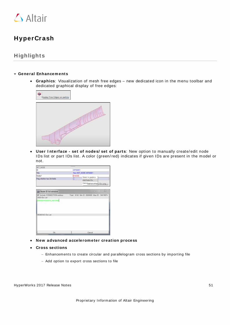
HyperWorks 2017 Release Notes 51
Proprietary Information of Altair Engineering
HyperCrash
Highlights
General Enhancements
• Graphics: Visualization of mesh free edges – new dedicated icon in the menu toolbar and dedicated graphical display of free edges:
• User Interface - set of nodes/set of parts: New option to manually create/edit node IDs list or part IDs list. A color (green/red) indicates if given IDs are present in the model or not.
• New advanced accelerometer creation process • Cross sections
− Enhancements to create circular and parallelogram cross sections by importing file − Add option to export cross sections to file
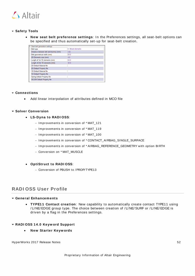
HyperWorks 2017 Release Notes 52
Proprietary Information of Altair Engineering
Safety Tools
• New seat belt preference settings: In the Preferences settings, all seat-belt options can be specified and thus automatically set-up for seat-belt creation.
Connections
• Add linear interpolation of attributes defined in MCO file
Solver Conversion
• LS-Dyna to RADIOSS: − Improvements in conversion of *MAT_121 − Improvements in conversion of *MAT_119 − Improvements in conversion of *MAT_100 − Improvements in conversion of *CONTACT_AIRBAG_SINGLE_SURFACE − Improvements in conversion of *AIRBAG_REFERENCE_GEOMETRY with option BIRTH − Conversion on *MAT_MUSCLE
• OptiStruct to RADIOSS: − Conversion of PBUSH to /PROP/TYPE13
RADIOSS User Profile
General Enhancements
• TYPE11 Contact creation: New capability to automatically create contact TYPE11 using /LINE/EDGE group type. The choice between creation of /LINE/SURF or /LINE/EDGE is driven by a flag in the Preferences settings.
RADIOSS 14.0 Keyword Support
• New Starter Keywords
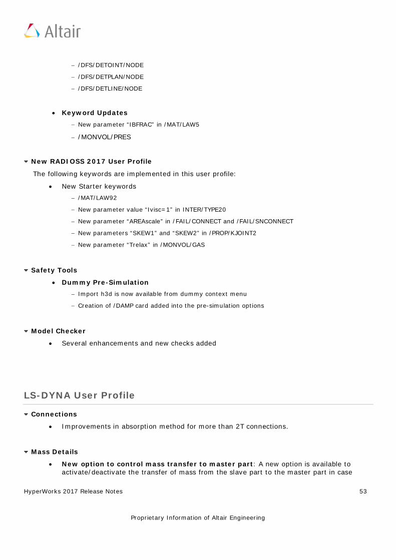
HyperWorks 2017 Release Notes 53
Proprietary Information of Altair Engineering
− /DFS/DETOINT/NODE − /DFS/DETPLAN/NODE − /DFS/DETLINE/NODE
• Keyword Updates − New parameter “IBFRAC” in /MAT/LAW5 − /MONVOL/PRES
New RADIOSS 2017 User Profile
The following keywords are implemented in this user profile:
• New Starter keywords − /MAT/LAW92 − New parameter value “Ivisc=1” in INTER/TYPE20 − New parameter “AREAscale” in /FAIL/CONNECT and /FAIL/SNCONNECT − New parameters “SKEW1” and “SKEW2” in /PROP/KJOINT2 − New parameter “Trelax” in /MONVOL/GAS
Safety Tools
• Dummy Pre-Simulation − Import h3d is now available from dummy context menu − Creation of /DAMP card added into the pre-simulation options
Model Checker
• Several enhancements and new checks added
LS-DYNA User Profile
Connections
• Improvements in absorption method for more than 2T connections.
Mass Details
• New option to control mass transfer to master part: A new option is available to activate/deactivate the transfer of mass from the slave part to the master part in case
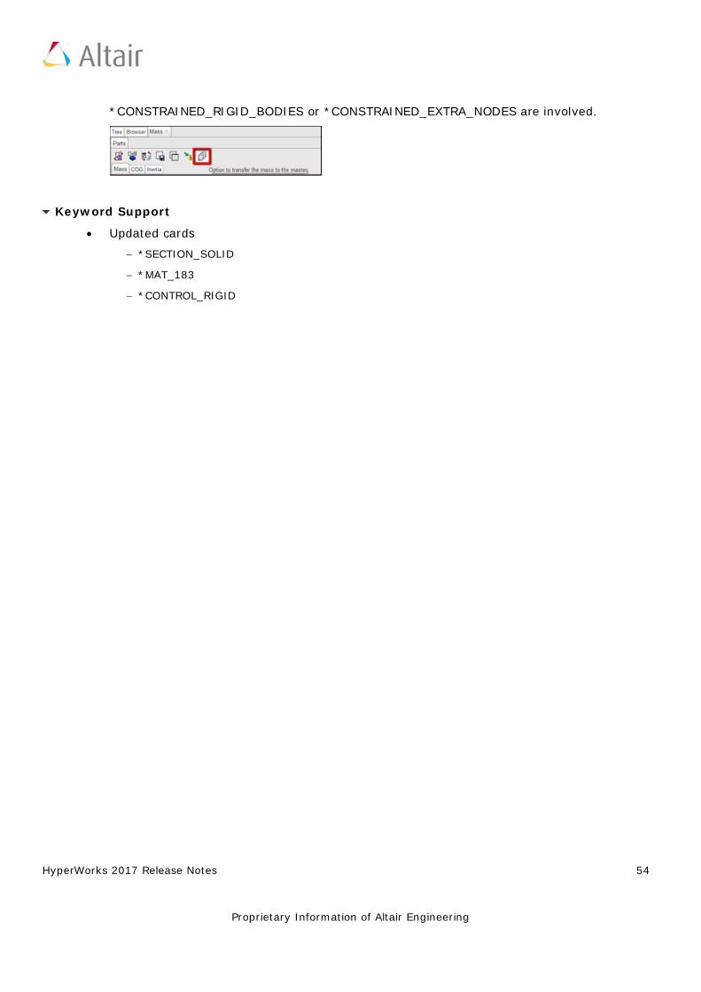
HyperWorks 2017 Release Notes 54
Proprietary Information of Altair Engineering
*CONSTRAINED_RIGID_BODIES or *CONSTRAINED_EXTRA_NODES are involved.
Keyword Support
• Updated cards − *SECTION_SOLID − *MAT_183 − *CONTROL_RIGID
HyperWorks 2017 Release Notes 55
Proprietary Information of Altair Engineering
HyperForm
Highlights
Springback Model Setup
Springback model setup in RADIOSS incremental profile has been updated to use MUMPS solver which reduce computational time and eliminates rigid body motion in the results.
Tube HydroForming Model Setup
Tube hydroforming model setup in RADIOSS incremental profile has been enhanced to use advanced solver features that reduce computational time while retaining accuracy.
Hot Stamping / Press Hardening Model Setup
Tube hydroforming model setup in RADIOSS incremental profile has been enhanced to use advanced solver features that reduce computational time while retaining accuracy.
Tube Bending Model Setup
Tube bending model setup in RADIOSS and LS-DYNA incremental profile has been enhanced with automatic option to calculate no of ball its pitch for mandrel based on bend radius, bend angle and tube outer diameter to use in modeling of tube bending process.
Incremental - Resolved Issues
• Tool normal points away from sheet leading to its contact with sheet being ignored • Time step calculated after trimming has been very small. • Smaller time step in models that has force generated by springs • Tool selection in the drawbead editor limited to one tool • Additional contact created between the blank as part of create input • Hidden components are displayed when the user invokes the tool build panel • Autoposition doesn’t clear penetration of tool with blanks for coarse mesh blanks
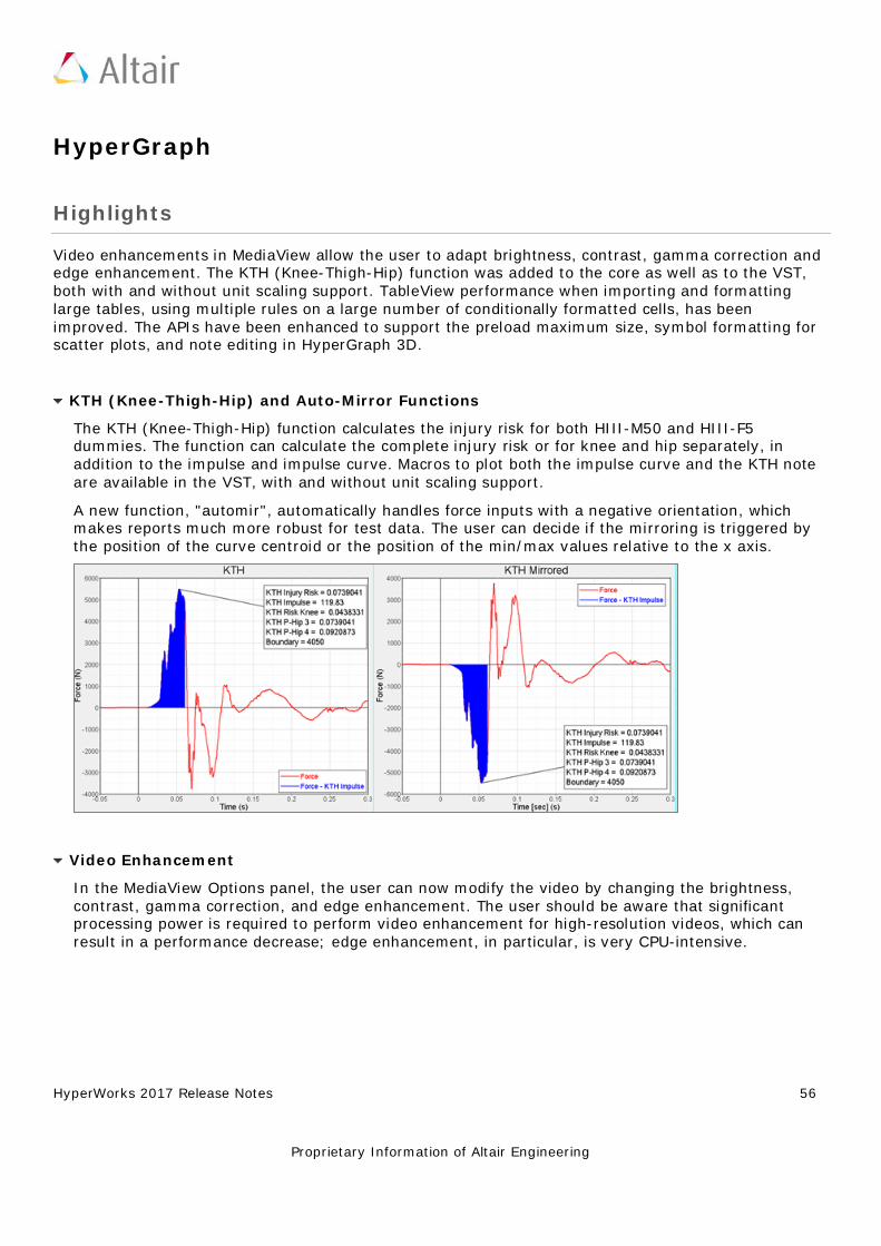
HyperWorks 2017 Release Notes 56
Proprietary Information of Altair Engineering
HyperGraph
Highlights
Video enhancements in MediaView allow the user to adapt brightness, contrast, gamma correction and edge enhancement. The KTH (Knee-Thigh-Hip) function was added to the core as well as to the VST, both with and without unit scaling support. TableView performance when importing and formatting large tables, using multiple rules on a large number of conditionally formatted cells, has been improved. The APIs have been enhanced to support the preload maximum size, symbol formatting for scatter plots, and note editing in HyperGraph 3D.
KTH (Knee-Thigh-Hip) and Auto-Mirror Functions
The KTH (Knee-Thigh-Hip) function calculates the injury risk for both HIII-M50 and HIII-F5 dummies. The function can calculate the complete injury risk or for knee and hip separately, in addition to the impulse and impulse curve. Macros to plot both the impulse curve and the KTH note are available in the VST, with and without unit scaling support.
A new function, "automir", automatically handles force inputs with a negative orientation, which makes reports much more robust for test data. The user can decide if the mirroring is triggered by the position of the curve centroid or the position of the min/max values relative to the x axis.
Video Enhancement
In the MediaView Options panel, the user can now modify the video by changing the brightness, contrast, gamma correction, and edge enhancement. The user should be aware that significant processing power is required to perform video enhancement for high-resolution videos, which can result in a performance decrease; edge enhancement, in particular, is very CPU-intensive.
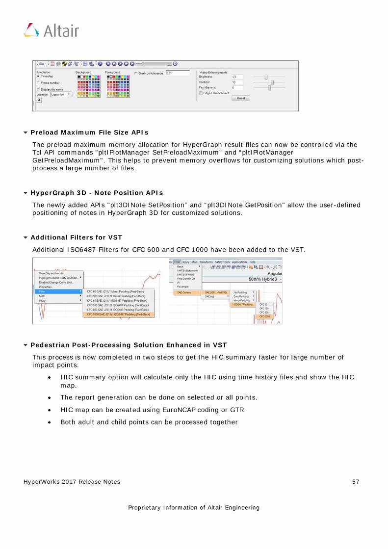
HyperWorks 2017 Release Notes 57
Proprietary Information of Altair Engineering
Preload Maximum File Size APIs
The preload maximum memory allocation for HyperGraph result files can now be controlled via the Tcl API commands "pltIPlotManager SetPreloadMaximum” and “pltIPlotManager GetPreloadMaximum". This helps to prevent memory overflows for customizing solutions which post-process a large number of files.
HyperGraph 3D - Note Position APIs
The newly added APIs "plt3DINote SetPosition” and “plt3DINote GetPosition" allow the user-defined positioning of notes in HyperGraph 3D for customized solutions.
Additional Filters for VST
Additional ISO6487 Filters for CFC 600 and CFC 1000 have been added to the VST.
Pedestrian Post-Processing Solution Enhanced in VST
This process is now completed in two steps to get the HIC summary faster for large number of impact points.
• HIC summary option will calculate only the HIC using time history files and show the HIC map.
• The report generation can be done on selected or all points. • HIC map can be created using EuroNCAP coding or GTR • Both adult and child points can be processed together
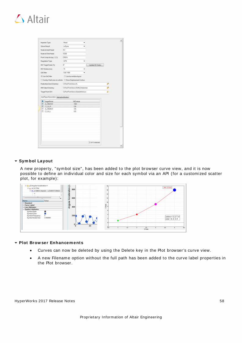
HyperWorks 2017 Release Notes 58
Proprietary Information of Altair Engineering
Symbol Layout
A new property, "symbol size", has been added to the plot browser curve view, and it is now possible to define an individual color and size for each symbol via an API (for a customized scatter plot, for example):
Plot Browser Enhancements
• Curves can now be deleted by using the Delete key in the Plot browser’s curve view. • A new Filename option without the full path has been added to the curve label properties in
the Plot browser.
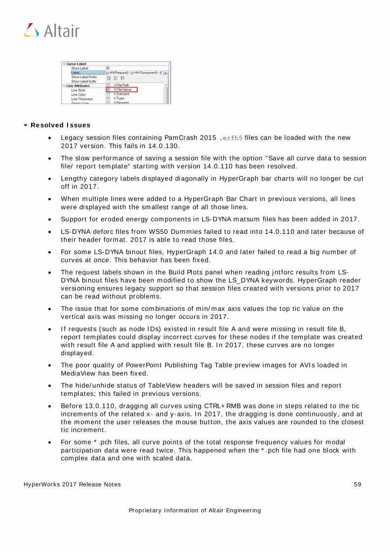
HyperWorks 2017 Release Notes 59
Proprietary Information of Altair Engineering
Resolved Issues
• Legacy session files containing PamCrash 2015 .erfh5 files can be loaded with the new 2017 version. This fails in 14.0.130.
• The slow performance of saving a session file with the option "Save all curve data to session file/ report template" starting with version 14.0.110 has been resolved.
• Lengthy category labels displayed diagonally in HyperGraph bar charts will no longer be cut off in 2017.
• When multiple lines were added to a HyperGraph Bar Chart in previous versions, all lines were displayed with the smallest range of all those lines.
• Support for eroded energy components in LS-DYNA matsum files has been added in 2017. • LS-DYNA deforc files from WS50 Dummies failed to read into 14.0.110 and later because of
their header format. 2017 is able to read those files. • For some LS-DYNA binout files, HyperGraph 14.0 and later failed to read a big number of
curves at once. This behavior has been fixed. • The request labels shown in the Build Plots panel when reading jntforc results from LS-
DYNA binout files have been modified to show the LS_DYNA keywords. HyperGraph reader versioning ensures legacy support so that session files created with versions prior to 2017 can be read without problems.
• The issue that for some combinations of min/max axis values the top tic value on the vertical axis was missing no longer occurs in 2017.
• If requests (such as node IDs) existed in result file A and were missing in result file B, report templates could display incorrect curves for these nodes if the template was created with result file A and applied with result file B. In 2017, these curves are no longer displayed.
• The poor quality of PowerPoint Publishing Tag Table preview images for AVIs loaded in MediaView has been fixed.
• The hide/unhide status of TableView headers will be saved in session files and report templates; this failed in previous versions.
• Before 13.0.110, dragging all curves using CTRL+RMB was done in steps related to the tic increments of the related x- and y-axis. In 2017, the dragging is done continuously, and at the moment the user releases the mouse button, the axis values are rounded to the closest tic increment.
• For some *.pch files, all curve points of the total response frequency values for modal participation data were read twice. This happened when the *.pch file had one block with complex data and one with scaled data.
HyperWorks 2017 Release Notes 60
Proprietary Information of Altair Engineering
• In 2017, the formula used to calculate the OLC++ value will use the absolute OLC value, which results in different values then in 14.0.120 and later. In addition, the OLC value will always be returned as a positive value.
• Editing entities of windows which are hidden in the graphics area but displayed in the plot browser was causing HyperGraph to crash. In the versions before 14.0.120, these windows were not displayed in the plot browser at all. In 2017, this behavior has been restored. Note: A hidden window can be created if the user creates curves in a multiple window page layout (e.g. 4 windows) and later changes the layout to a layout with less windows (e.g. 2 windows).
HyperWorks 2017 Release Notes 61
Proprietary Information of Altair Engineering
HyperMath
HyperMath version 2017 will be the last major release supported. After 2017, HyperMath will be deprecated and no longer maintained or released in future versions of HyperWorks.
HyperMath is progressively replaced by solidThinking Compose.
Compose 2017 is available and offers a new language, OML, that provides extended features and new syntax.
HML and OML languages are NOT compatible, and it is recommended that you migrate existing HML scripts to OML.
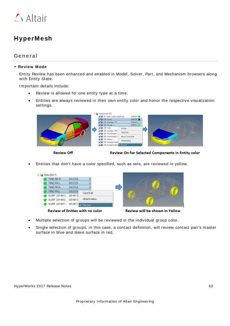
HyperWorks 2017 Release Notes 62
Proprietary Information of Altair Engineering
HyperMesh
General
Review Mode
Entity Review has been enhanced and enabled in Model, Solver, Part, and Mechanism browsers along with Entity State.
Important details include:
• Review is allowed for one entity type at a time. • Entities are always reviewed in their own entity color and honor the respective visualization
settings.
• Entities that don't have a color specified, such as sets, are reviewed in yellow.
• Multiple selection of groups will be reviewed in the individual group color. • Single selection of groups, in this case, a contact definition, will review contact pair’s master
surface in blue and slave surface in red.
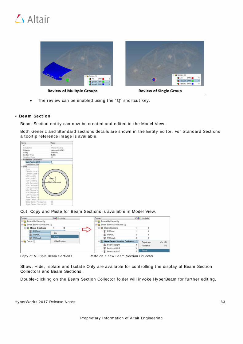
HyperWorks 2017 Release Notes 63
Proprietary Information of Altair Engineering
.
• The review can be enabled using the “Q” shortcut key.
Beam Section
Beam Section entity can now be created and edited in the Model View.
Both Generic and Standard sections details are shown in the Entity Editor. For Standard Sections a tooltip reference image is available.
Cut, Copy and Paste for Beam Sections is available in Model View.
Copy of Multiple Beam Sections Paste on a new Beam Section Collector
Show, Hide, Isolate and Isolate Only are available for controlling the display of Beam Section Collectors and Beam Sections.
Double-clicking on the Beam Section Collector folder will invoke HyperBeam for further editing.
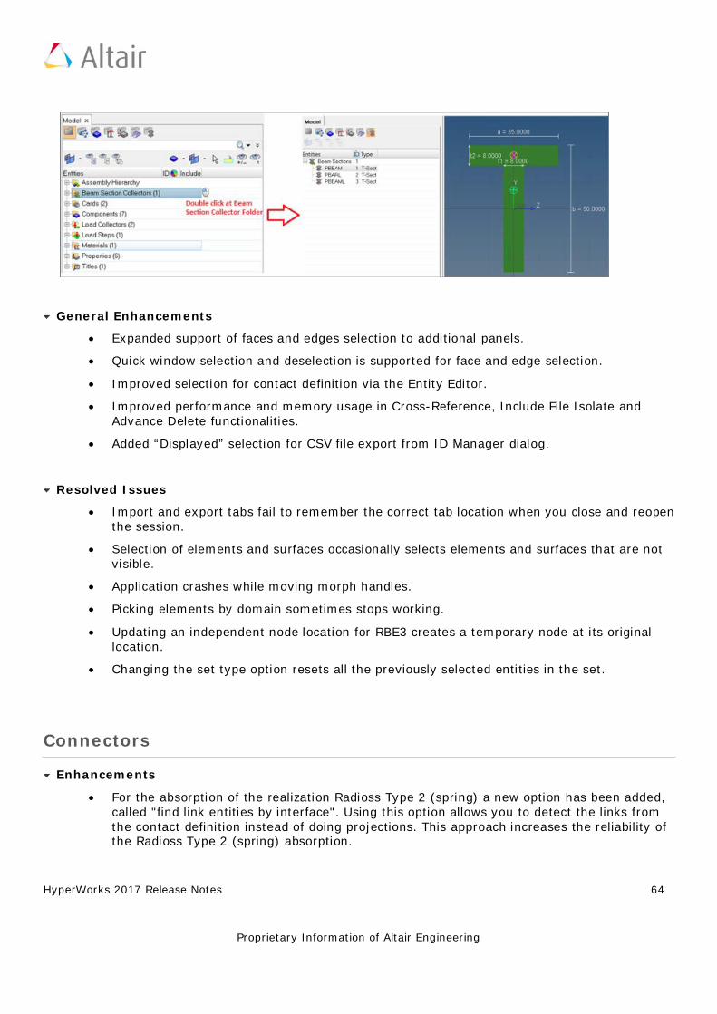
HyperWorks 2017 Release Notes 64
Proprietary Information of Altair Engineering
General Enhancements
• Expanded support of faces and edges selection to additional panels. • Quick window selection and deselection is supported for face and edge selection. • Improved selection for contact definition via the Entity Editor. • Improved performance and memory usage in Cross-Reference, Include File Isolate and
Advance Delete functionalities. • Added “Displayed” selection for CSV file export from ID Manager dialog.
Resolved Issues
• Import and export tabs fail to remember the correct tab location when you close and reopen the session.
• Selection of elements and surfaces occasionally selects elements and surfaces that are not visible.
• Application crashes while moving morph handles. • Picking elements by domain sometimes stops working. • Updating an independent node location for RBE3 creates a temporary node at its original
location. • Changing the set type option resets all the previously selected entities in the set.
Connectors
Enhancements
• For the absorption of the realization Radioss Type 2 (spring) a new option has been added, called "find link entities by interface". Using this option allows you to detect the links from the contact definition instead of doing projections. This approach increases the reliability of the Radioss Type 2 (spring) absorption.
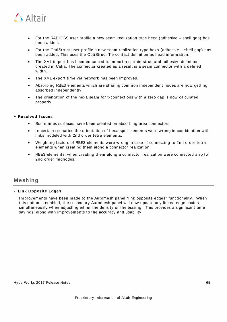
HyperWorks 2017 Release Notes 65
Proprietary Information of Altair Engineering
• For the RADIOSS user profile a new seam realization type hexa (adhesive – shell gap) has been added.
• For the OptiStruct user profile a new seam realization type hexa (adhesive – shell gap) has been added. This uses the OptiStruct Tie contact definition as head information.
• The XML import has been enhanced to import a certain structural adhesive definition created in Catia. The connector created as a result is a seam connector with a defined width.
• The XML export time via network has been improved. • Absorbing RBE3 elements which are sharing common independent nodes are now getting
absorbed independently. • The orientation of the hexa seam for t-connections with a zero gap is now calculated
properly.
Resolved Issues
• Sometimes surfaces have been created on absorbing area connectors. • In certain scenarios the orientation of hexa spot elements were wrong in combination with
links modeled with 2nd order tetra elements. • Weighting factors of RBE3 elements were wrong in case of connecting to 2nd order tetra
elements when creating them along a connector realization. • RBE3 elements, when creating them along a connector realization were connected also to
2nd order midnodes.
Meshing
Link Opposite Edges
Improvements have been made to the Automesh panel “link opposite edges” functionality. When this option is enabled, the secondary Automesh panel will now update any linked edge chains simultaneously when adjusting either the density or the biasing. This provides a significant time savings, along with improvements to the accuracy and usability.
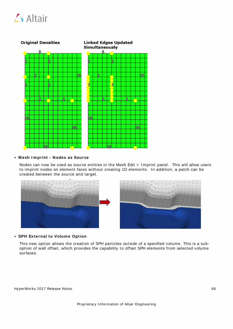
HyperWorks 2017 Release Notes 66
Proprietary Information of Altair Engineering
Mesh Imprint - Nodes as Source
Nodes can now be used as source entities in the Mesh Edit > Imprint panel. This will allow users to imprint nodes on element faces without creating 1D elements. In addition, a patch can be created between the source and target.
SPH External to Volume Option
This new option allows the creation of SPH particles outside of a specified volume. This is a sub-option of wall offset, which provides the capability to offset SPH elements from selected volume surfaces.
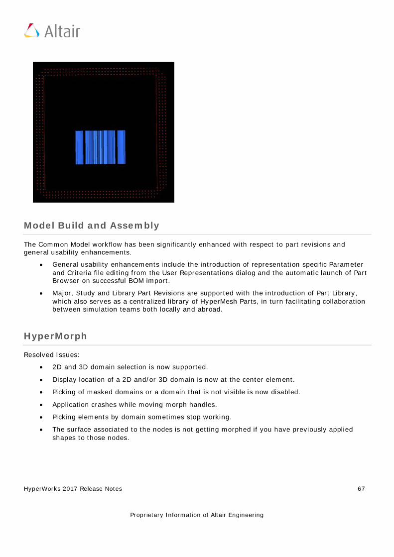
HyperWorks 2017 Release Notes 67
Proprietary Information of Altair Engineering
Model Build and Assembly
The Common Model workflow has been significantly enhanced with respect to part revisions and general usability enhancements.
• General usability enhancements include the introduction of representation specific Parameter and Criteria file editing from the User Representations dialog and the automatic launch of Part Browser on successful BOM import.
• Major, Study and Library Part Revisions are supported with the introduction of Part Library, which also serves as a centralized library of HyperMesh Parts, in turn facilitating collaboration between simulation teams both locally and abroad.
HyperMorph
Resolved Issues:
• 2D and 3D domain selection is now supported. • Display location of a 2D and/or 3D domain is now at the center element. • Picking of masked domains or a domain that is not visible is now disabled. • Application crashes while moving morph handles. • Picking elements by domain sometimes stop working. • The surface associated to the nodes is not getting morphed if you have previously applied
shapes to those nodes.
HyperWorks 2017 Release Notes 68
Proprietary Information of Altair Engineering
APIs
Highlights
• The masking of individual surfaces of solids has thus far not been supported. To mask a solid surface, the solid must first be deleted, and then individual surfaces can be masked. In addition, user scripts may have come to rely that when a solid is displayed, all of its surfaces are also displayed. However, masking of individual surfaces of solids will be supported starting with the 2018 release. It is important for users to take action to update the logic in their scripts now, so that they will continue to work when the new support is available.
• See the 2017 API Programmer’s Guide for full details on all new, modified and deprecated commands, as well as other items of note.
Resolved Issues
• Resolved several memory and performance issues with the hm_collision... family of commands when using the allowable_depth option for hm_collisioninit.
HyperWorks 2017 Release Notes 69
Proprietary Information of Altair Engineering
CAD and Solver Interfaces
Abaqus Interface ANSYS Interface CAD Interfaces EXODUS Interface LS-DYNA Interface Nastran Interface OptiStruct Interface PAM CRASH 2G Interface RADIOSS Interface
Samcef Interface
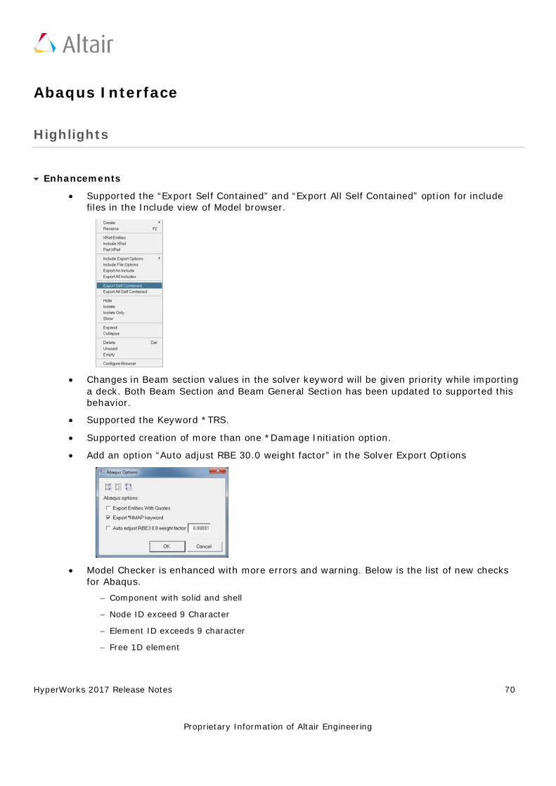
HyperWorks 2017 Release Notes 70
Proprietary Information of Altair Engineering
Abaqus Interface
Highlights
Enhancements
• Supported the “Export Self Contained” and “Export All Self Contained” option for include files in the Include view of Model browser.
• Changes in Beam section values in the solver keyword will be given priority while importing a deck. Both Beam Section and Beam General Section has been updated to supported this behavior.
• Supported the Keyword *TRS. • Supported creation of more than one *Damage Initiation option. • Add an option “Auto adjust RBE 30.0 weight factor” in the Solver Export Options
• Model Checker is enhanced with more errors and warning. Below is the list of new checks for Abaqus.
− Component with solid and shell − Node ID exceed 9 Character − Element ID exceeds 9 character − Free 1D element
HyperWorks 2017 Release Notes 71
Proprietary Information of Altair Engineering
− RBE2 with constrained dependent nodes − Free Rigid elements − Free RBE3 elements − RBE3 dof connected to solid − Zero-length CONN3D2 − Free spring elements − Beam Property with Zero cross section area − Property missing card image − Shell Section thickness is not defined − Shell Section Composite thickness is not defined
Solver Conversion
Abaqus to OptiStruct Solver Conversion Enhancements
• *CONTACT CONTROLS are converted to CNTSTB and is mapped to loadstep • *SURFACE INTERACTION, Separation(No/Yes) is mapped to
Property,PCONT,Separation(No/Yes) • *ELASTIC, TYPE = ENGINEERING CONSTANTS is converted to MAT9ORT • *STATIC load step with Int_INC it is mapped to NLPARM load collector with
NINC=1/Int_INC • *STATIC load step with MinIcr it is mapped to NLADAPT,DTMIN load collector • *STATIC load step with MaxIncr it is mapped to NLADAPT,DTMAX load collector • *STEP with unsymm=yes is converted to PARAM, UNSYMSLV
Nastran to Abaqus Solver Conversion Enhancements
• BSURF is converted to *SURFACE ELEMENT • BCBODY in BCTABLE is mapped to CONTACT PAIR • Friction in BCTABLE is mapped to *SURFACE INTERACTION
Resolved Issues
• Card Editor shows node and element ID with 9 digits. • The name of the DCOUP element is preserved during export and Import • Resolved an issue with *.csv file import in table entity • Resolved an issue with material name export with “Export an Include” option
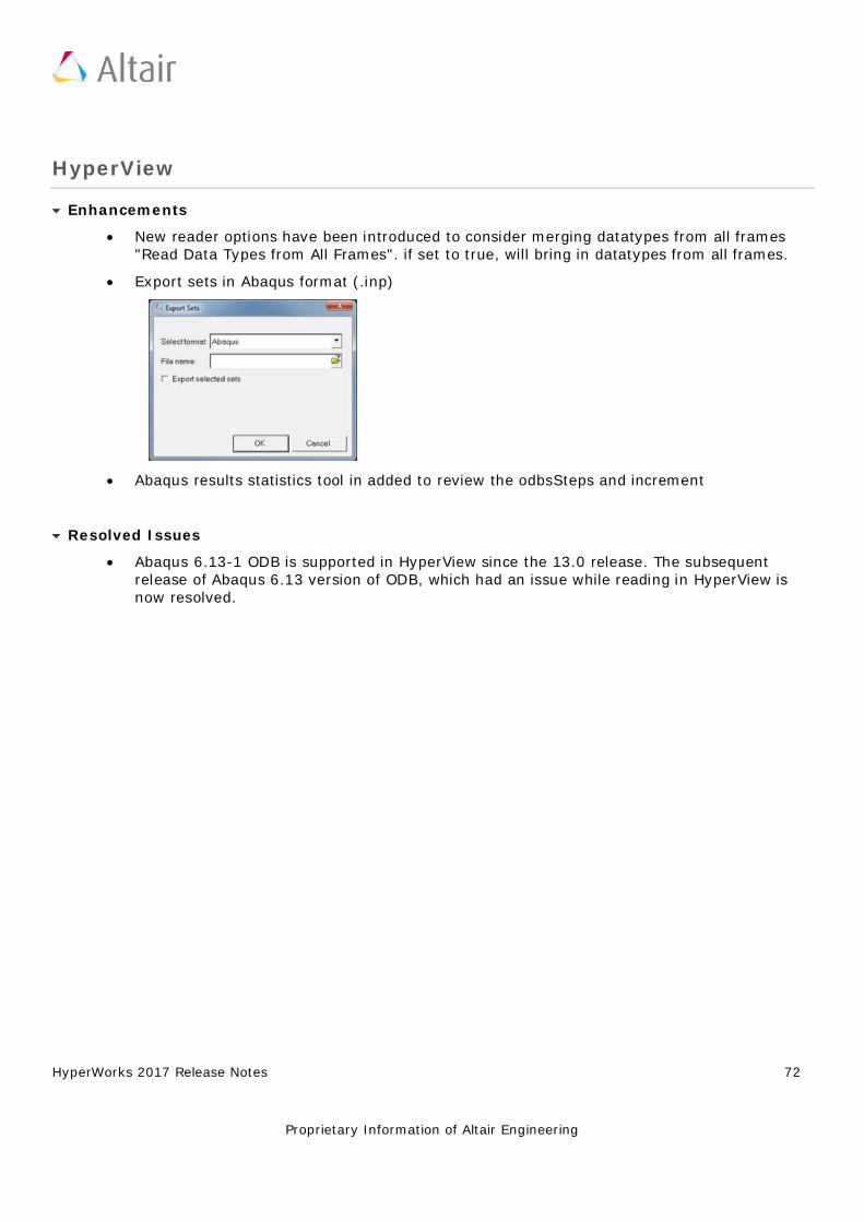
HyperWorks 2017 Release Notes 72
Proprietary Information of Altair Engineering
HyperView
Enhancements
• New reader options have been introduced to consider merging datatypes from all frames "Read Data Types from All Frames". if set to true, will bring in datatypes from all frames.
• Export sets in Abaqus format (.inp)
• Abaqus results statistics tool in added to review the odbsSteps and increment
Resolved Issues
• Abaqus 6.13-1 ODB is supported in HyperView since the 13.0 release. The subsequent release of Abaqus 6.13 version of ODB, which had an issue while reading in HyperView is now resolved.
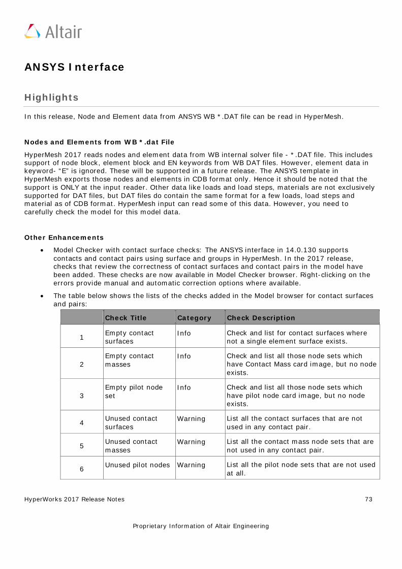
HyperWorks 2017 Release Notes 73
Proprietary Information of Altair Engineering
ANSYS Interface
Highlights
In this release, Node and Element data from ANSYS WB *.DAT file can be read in HyperMesh.
Nodes and Elements from WB *.dat File
HyperMesh 2017 reads nodes and element data from WB internal solver file - *.DAT file. This includes support of node block, element block and EN keywords from WB DAT files. However, element data in keyword- “E” is ignored. These will be supported in a future release. The ANSYS template in HyperMesh exports those nodes and elements in CDB format only. Hence it should be noted that the support is ONLY at the input reader. Other data like loads and load steps, materials are not exclusively supported for DAT files, but DAT files do contain the same format for a few loads, load steps and material as of CDB format. HyperMesh input can read some of this data. However, you need to carefully check the model for this model data.
Other Enhancements
• Model Checker with contact surface checks: The ANSYS interface in 14.0.130 supports contacts and contact pairs using surface and groups in HyperMesh. In the 2017 release, checks that review the correctness of contact surfaces and contact pairs in the model have been added. These checks are now available in Model Checker browser. Right-clicking on the errors provide manual and automatic correction options where available.
• The table below shows the lists of the checks added in the Model browser for contact surfaces and pairs:
Check Title Category Check Description
1 Empty contact surfaces
Info Check and list for contact surfaces where not a single element surface exists.
2 Empty contact masses
Info Check and list all those node sets which have Contact Mass card image, but no node exists.
3 Empty pilot node set
Info Check and list all those node sets which have pilot node card image, but no node exists.
4 Unused contact surfaces
Warning List all the contact surfaces that are not used in any contact pair.
5 Unused contact masses
Warning List all the contact mass node sets that are not used in any contact pair.
6 Unused pilot nodes Warning List all the pilot node sets that are not used at all.
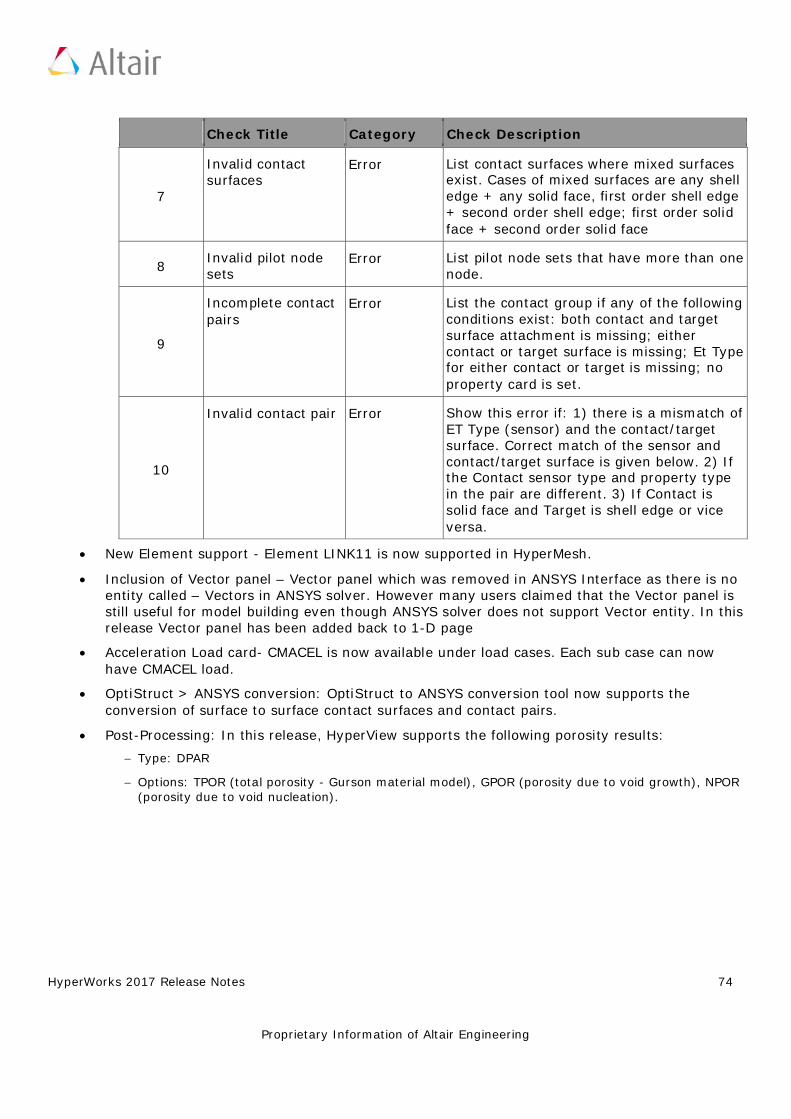
HyperWorks 2017 Release Notes 74
Proprietary Information of Altair Engineering
Check Title Category Check Description
7
Invalid contact surfaces
Error List contact surfaces where mixed surfaces exist. Cases of mixed surfaces are any shell edge + any solid face, first order shell edge + second order shell edge; first order solid face + second order solid face
8 Invalid pilot node sets
Error List pilot node sets that have more than one node.
9
Incomplete contact pairs
Error List the contact group if any of the following conditions exist: both contact and target surface attachment is missing; either contact or target surface is missing; Et Type for either contact or target is missing; no property card is set.
10
Invalid contact pair Error Show this error if: 1) there is a mismatch of ET Type (sensor) and the contact/target surface. Correct match of the sensor and contact/target surface is given below. 2) If the Contact sensor type and property type in the pair are different. 3) If Contact is solid face and Target is shell edge or vice versa.
• New Element support - Element LINK11 is now supported in HyperMesh. • Inclusion of Vector panel – Vector panel which was removed in ANSYS Interface as there is no
entity called – Vectors in ANSYS solver. However many users claimed that the Vector panel is still useful for model building even though ANSYS solver does not support Vector entity. In this release Vector panel has been added back to 1-D page
• Acceleration Load card- CMACEL is now available under load cases. Each sub case can now have CMACEL load.
• OptiStruct > ANSYS conversion: OptiStruct to ANSYS conversion tool now supports the conversion of surface to surface contact surfaces and contact pairs.
• Post-Processing: In this release, HyperView supports the following porosity results: − Type: DPAR − Options: TPOR (total porosity - Gurson material model), GPOR (porosity due to void growth), NPOR
(porosity due to void nucleation).
HyperWorks 2017 Release Notes 75
Proprietary Information of Altair Engineering
CAD Interfaces
Highlights
Updated CAD Version Support
The following CAD versions are newly supported:
• CREO 3 M090 • NX 11 (native reader)
NX Native Reader Support
Support for the NX native reader has been updated to add the NX 11 libraries, and drop the NX 8.5 libraries. This means the NX 8.5 libraries can no longer be used for the native NX reader. However, NX files from older versions can still be imported via all supported NX library versions. The third-party NX reader also supports NX files through version 10.0, without the need for the NX libraries.
Layers Support for STEP Export
This enhancement allows the entities in each HyperMesh component to be assigned to the layer number in the STEP file corresponding to that component ID.
HyperWorks 2017 Release Notes 76
Proprietary Information of Altair Engineering
EXODUS Interface
Highlights
In HyperWorks 2017, the “Exodus-Sierra_SD” interface has been enhanced with new features, as listed below.
Enhancements
• I/O and the user interface is provided for Rigid RBAR and RROD and spring type of elements. • Definition of side set with 1D edge and 2D/3D faces is enhanced with the definition of
distribution factors. • Selection of faces to define contact surf/side set honor display status. • Export of *.ex2 only or *.ex2 + *.inp is now possible. • Only imported or edited field attributes are exported for materials, contacts and solution
controls. • Data models with multiple element types in a single component (Element Block) will no longer
export element blocks with duplicate names into *.ex2 files.
HyperWorks 2017 Release Notes 77
Proprietary Information of Altair Engineering
LS-DYNA Interface
Highlights
This release extends the coverage of LS-DYNA with RIGIDWALL as new entity, improved and added additional model checks, improved find connectivity, accurate mass calculation and improved ID Manager etc.
New Entity for *RIGIDWALL
The keyword was originally mapped to a HyperMesh “group” entity that was shared with other keywords such as contact. It is now mapped to new independent entity with its own ID, icon, dedicated graphics and creation process. Now creation of RIGIDWALL entity is removed from the panel. Also, added entity related model checks under model checker are available. Creation and export of extra node for base of RIGIDWALL is now removed. The following behavior is implemented:
• Removed any ID renumbering that occurred when a RIGIDWALL keyword shared the same ID with other “group entities”.
• Such keywords are mapped to new entities automatically upon reading ASCII or BINARY files without data loss.
An enhanced graphical representation to facilitate identification and selection in the graphics. Show, Hide, Isolate & Isolate Only have better results based on NSID, NSIDX & BOXID.
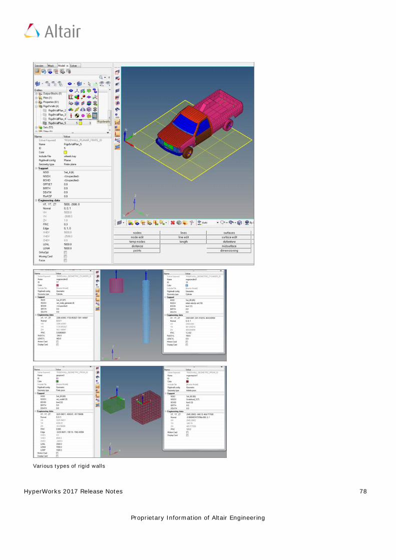
HyperWorks 2017 Release Notes 78
Proprietary Information of Altair Engineering
Various types of rigid walls
HyperWorks 2017 Release Notes 79
Proprietary Information of Altair Engineering
Updated Keywords
The keywords supported with option _DISPLAY:
• *RIGIDWALL_GEOMETRIC_CYLINDER_DISPLAY • *RIGIDWALL_GEOMETRIC_CYLINDER_MOTION_DISPLAY • *RIGIDWALL_GEOMETRIC_FLAT_DISPLAY • *RIGIDWALL_GEOMETRIC_FLAT_DISPLAY(FINITE) • *RIGIDWALL_GEOMETRIC_FLAT_MOTION_DISPLAY • *RIGIDWALL_GEOMETRIC_FLAT_MOTION_DISPLAY(FINITE) • *RIGIDWALL_GEOMETRIC_PRISM_DISPLAY • *RIGIDWALL_GEOMETRIC_PRISM_DISPLAY(FINITE) • *RIGIDWALL_GEOMETRIC_PRISM_MOTION_DISPLAY • *RIGIDWALL_GEOMETRIC_PRISM_MOTION_DISPLAY(FINITE) • *RIGIDWALL_GEOMETRIC_SPHERE_DISPLAY • *RIGIDWALL_GEOMETRIC_SPHERE_MOTION_DISPLAY • *RIGIDWALL_PLANAR_FINITE_MOVING_DISPLAY • *RIGIDWALL_PLANAR_FINITE_MOVING_FORCES_DISPLAY • *RIGIDWALL_PLANAR_MOVING_DISPLAY • *RIGIDWALL_PLANAR_MOVING_FORCES_DISPLAY
General Fixes
• Removed Keyword960 and Keyword970 from user profile dialog. Templates are available in the installation and can be loaded; however they are no longer maintained.
• FORCES_MOVING is changed to MOVING_FORCES and FORCES_FINITE is changed to FINITE_FORCES under the keyword *RIGIDWALL_PLANAR.
• *RIGIDWALL_PLANAR_ORTHO_FINITE is listed in the Solver browser • Import and export the include file having + in the name also name or path spread across
multiple lines.
HyperWorks 2017 Release Notes 80
Proprietary Information of Altair Engineering
Nastran Interface
Highlights
Solver Cards Additions and Enhancements
• DMIG card is supported as "Direct Matrix Input" entity • ACCEL, ACCEL1
General Enhancements
• OFFSET option removed for CBEAM element in NX Nastran
Solver Conversion
Nastran to Abaqus solver conversion enhancements:
• BSURF is converted to *SURFACE ELEMENT • BCBODY in BCTABLE is mapped to CONTACT PAIR • Friction in BCTABLE is mapped to *SURFACE INTERACTION
Resolved Issues
• Output Nastran subcases in order • BCPROP with formulae creation results in error • RBE3 in long-format Nastran solver deck triggers fatal error • Import issue while reading NSML1 with 2 duplicated SID
HyperWorks 2017 Release Notes 81
Proprietary Information of Altair Engineering
OptiStruct Interface
Highlights
Structural Linear and Nonlinear Analysis Enhancements
• ACCEL, ACCEL1 and ACCEL2 • Continuous sliding CONSLI option in Track field for S2S in CONTACT card • MODCHG - Removing and reactivating of contact pairs/Sets during the course of a
simulation • Results output on the fly NLMON card • One strep transient thermal stress analysis(OSTTS) supported in Nonlinear analysis • DIRECT option on NLADAPT • New option "DOF" at 6th field for TIE contact • SEPARATION field in PCONT card • RESTART card support • STATSUB(BRAKE) option in Complex Eigen modal subcase to support Brake Squeal Analysis • STATSUB(PRELOAD) in DTRAN and MTRAN subcases • SET for RANDOM case control • Add scaling to PBUSHT • GENER option on PBUSH1D • DAMPER TABLE on PBUSH1D • DMIG bulk card supported as "Direct Matrix Input" entity • Parameters entity support to parameterize entities in HyperMesh
Fatigue Card Enhancements
• Seam weld fatigue • Spotweld fatigue • FKM option for mean stress correction in SN uniaxial fatigue • Support TABLE for D value in PWELD
Optimization Card Enhancements
• FRF based mode tracking • RMS function support for DRESP1, DRESP2 and DLINK2 cards
HyperWorks 2017 Release Notes 82
Proprietary Information of Altair Engineering
Solver Conversion Enhancements
Abaqus > OptiStruct
• *CONTACT CONTROLS are converted to CNTSTB and is mapped to loadstep • *SURFACE INTERACTION, Separation(No/Yes) is mapped to PCONT,Separation(No/Yes) • *ELASTIC, TYPE = ENGINEERING CONSTANTS is converted to MAT9ORT • *STATIC load step with Int_INC it is mapped to NLPARM load collector with
NINC=1/Int_INC • *STATIC load step with MinIcr it is mapped to NLADAPT,DTMIN load collector • *STATIC load step with MaxIncr it is mapped to NLADAPT,DTMAX load • Multiple resolved issues
Solver Card Additions and Enhancements
• PARAM, NAST+ • PARAM, KISSSOFT • MODCHG • ACCEL/ACCEL1/ACCEL2 • STATSUB(BRAKE) • NLMON • DMIG • PFATSMW • PFATSPW
HyperView Reader Enhancements
• Support GPSTRAIN in OptiStruct OP2 result • PSD or RMS corner results in OP2 format are now supported • Fluid element forces (OEF) in OP2 file are now supported • CPYRA Elements support from OP2 file
Resolved Issues
• FORCE2 info is lost on import in HyperMesh without warnings or error • Error in HyperMesh opti control when specifying DDVOPT=3 • Constraints with subcase dependent DRESP3 responses

HyperWorks 2017 Release Notes 83
Proprietary Information of Altair Engineering
• Load step browser: Invalid loadcol error when two load collectors are used • NLOUT parm missing during import • Loadcols are not associated to Load steps • Properties are not assigned correctly for model with mixed property in long format
HyperWorks 2017 Release Notes 84
Proprietary Information of Altair Engineering
PAM CRASH 2G Interface
Resolved Issues
• Duplicate name support for keyword title on export. • Fixed export issues for formula set having ADD & REMOVE (DEL) and HM binary model with ID
range and selection(list). • Resolved an application crash related to deleting include files
.
HyperWorks 2017 Release Notes 85
Proprietary Information of Altair Engineering
RADIOSS Interface
Highlights
This release extends the coverage of RADIOSS keywords supported for RADIOSS versions V14.0 and V14.0.220.
New RADIOSS Starter Keywords
• /MAT/LAW87 • /DFS/DETPLAN (added in RADIOSS V13 also) • /DFS/DETPLAN_NODE • /PARAMETER/GLOBAL/TEXT
Updated RADIOSS Keywords
• /PROP/SPR_BEAM (RADIOSS V13 & V14) • /PROP/SPR_PUL (RADIOSS V13 & V14) • /PROP/SH_FABR (RADIOSS V13 & V14) • /PROP/SOL_ORTH (RADIOSS V14) • /DT/AMS (RADIOSS V12 V13 & V14) • /MAT/LAW66 (RADIOSS V12 V13 & V14)
Parameter Enhancement
• Parameter type TEXT (string) is now supported by keyword /PARAMETER/GLOBAL/TEXT for the fields of Load Collectors.
• Parameterization is supported for the fields like legal values, missing integer fields and some elements (RBODY & RLINK)
LS-Dyna to RADIOSS Solver Conversion Enhancements
• *MAT_SPRING_ELASTIC is converted to /PROP/TYPE13 • *MAT_SEATBELT is converted to /PROP/SPRING • *MAT_MOONEY_RIVLIN_RUBBER is converted to M42_OGDEN /M69 • *MAT_LOW_DENSITY_FOAM is converted to /MAT/LAW38
HyperWorks 2017 Release Notes 86
Proprietary Information of Altair Engineering
PamCrash to RADIOSS Solver Conversion Enhancements
• MATERIAL_SOLID/TYPE 45" to Radioss "/MAT/LAW70 (FOAM_TAB)".
HyperWorks 2017 Release Notes 87
Proprietary Information of Altair Engineering
Samcef Interface
Highlights
In this release, a new type of element is supported: FOU3 element. This element is supported as a gap element in the HyperMesh interface. A new property named MCCFOU3 should be assigned to the element.
Resolved Issues
• In the previous release, if a property was assigned to the component at the model import, this property was assigned to the elements. Now at the import, the property will stay with the component.
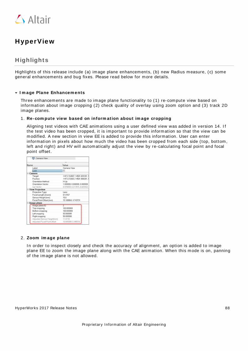
HyperWorks 2017 Release Notes 88
Proprietary Information of Altair Engineering
HyperView
Highlights
Highlights of this release include (a) image plane enhancements, (b) new Radius measure, (c) some general enhancements and bug fixes. Please read below for more details.
Image Plane Enhancements
Three enhancements are made to image plane functionality to (1) re-compute view based on information about image cropping (2) check quality of overlay using zoom option and (3) track 2D image planes.
1. Re-compute view based on information about image cropping Aligning test videos with CAE animations using a user defined view was added in version 14. If the test video has been cropped, it is important to provide information so that the view can be modified. A new section in view EE is added to provide this information. User can enter information in pixels about how much the video has been cropped from each side (top, bottom, left and right) and HV will automatically adjust the view by re-calculating focal point and focal point offset.
2. Zoom image plane In order to inspect closely and check the accuracy of alignment, an option is added to image plane EE to zoom the image plane along with the CAE animation. When this mode is on, panning of the image plane is not allowed.
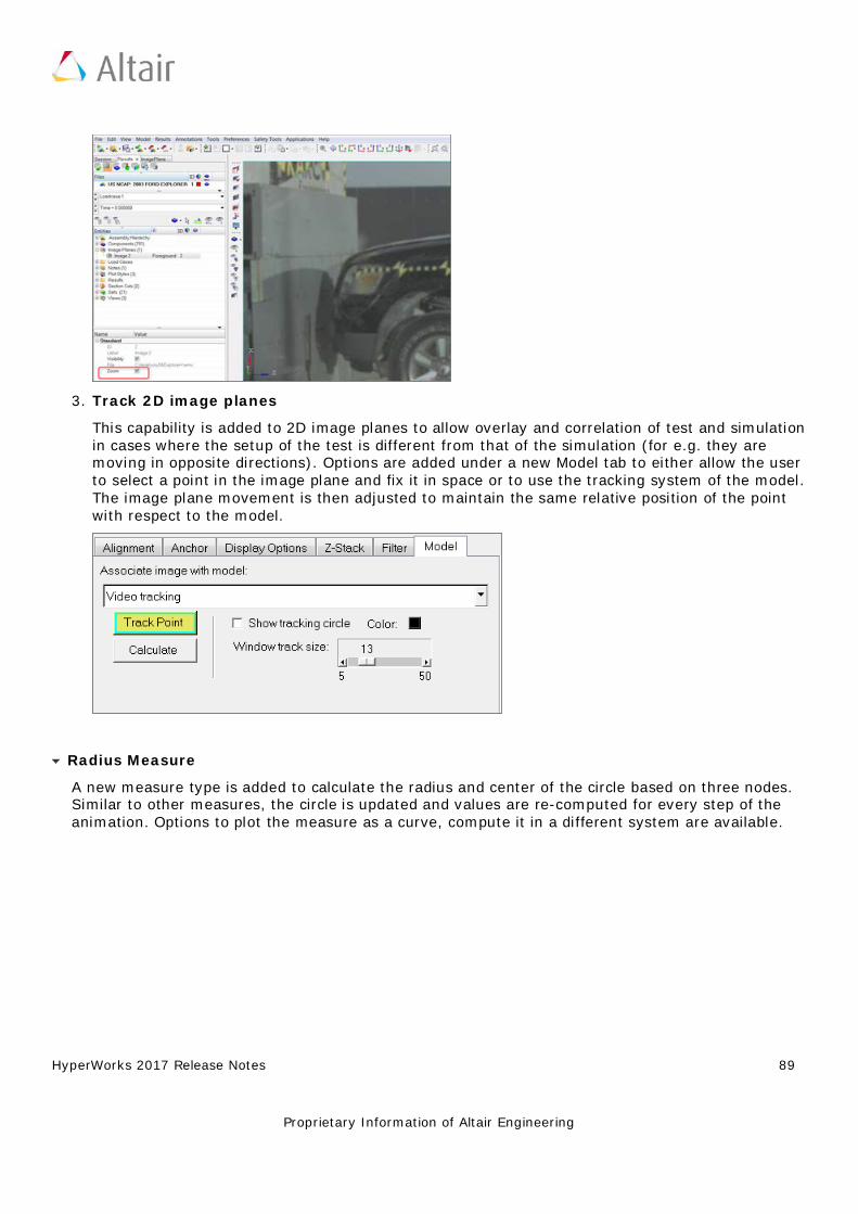
HyperWorks 2017 Release Notes 89
Proprietary Information of Altair Engineering
3. Track 2D image planes This capability is added to 2D image planes to allow overlay and correlation of test and simulation in cases where the setup of the test is different from that of the simulation (for e.g. they are moving in opposite directions). Options are added under a new Model tab to either allow the user to select a point in the image plane and fix it in space or to use the tracking system of the model. The image plane movement is then adjusted to maintain the same relative position of the point with respect to the model.
Radius Measure
A new measure type is added to calculate the radius and center of the circle based on three nodes. Similar to other measures, the circle is updated and values are re-computed for every step of the animation. Options to plot the measure as a curve, compute it in a different system are available.
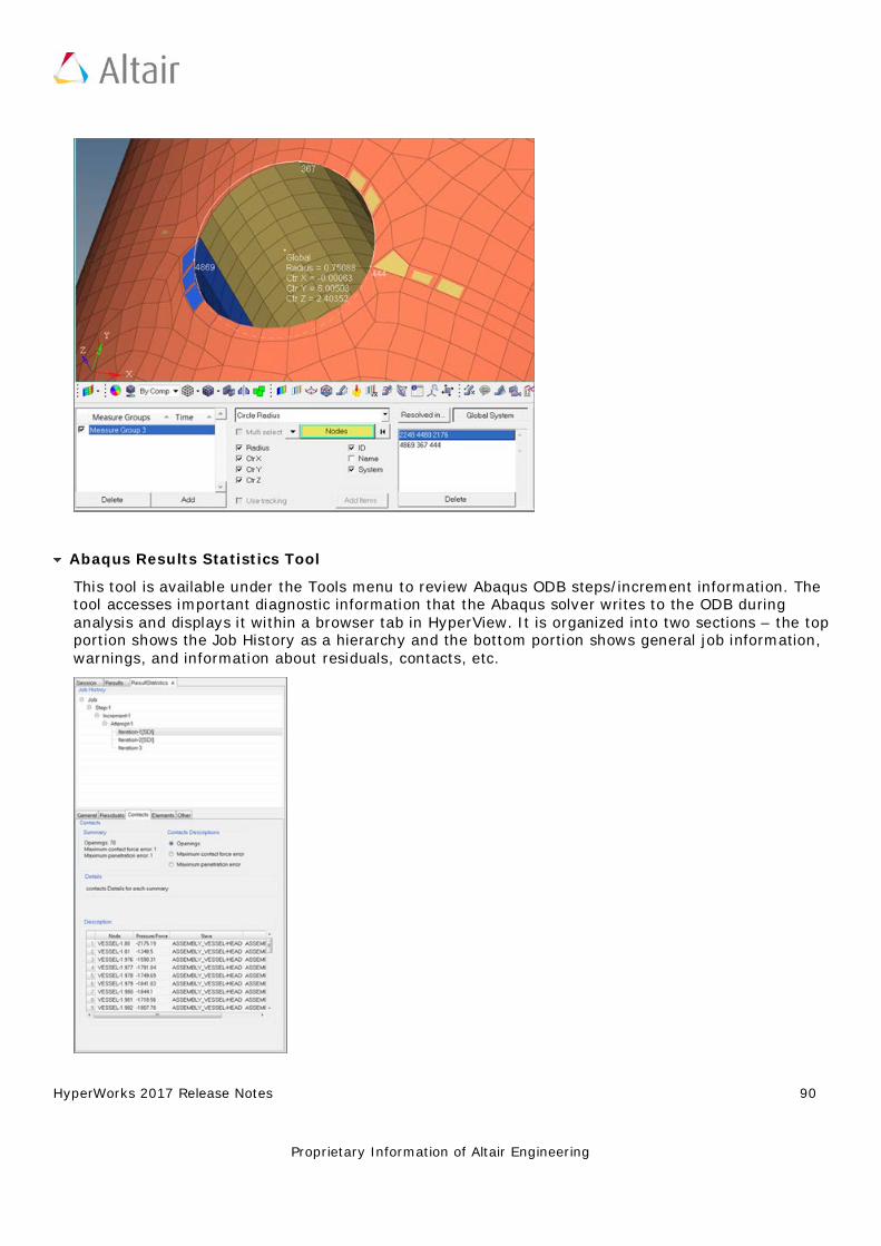
HyperWorks 2017 Release Notes 90
Proprietary Information of Altair Engineering
Abaqus Results Statistics Tool
This tool is available under the Tools menu to review Abaqus ODB steps/increment information. The tool accesses important diagnostic information that the Abaqus solver writes to the ODB during analysis and displays it within a browser tab in HyperView. It is organized into two sections – the top portion shows the Job History as a hierarchy and the bottom portion shows general job information, warnings, and information about residuals, contacts, etc.
HyperWorks 2017 Release Notes 91
Proprietary Information of Altair Engineering
General Enhancements
• New preference option is added to reverse the background of a non-transparent legend when capturing an image or video.
• Image capture is enhanced to properly capture high-resolution images. • Ability to set precision and format of displayed values is provided in the tensor panel. • New report template parameters for parametrizing contour datatype and data component is
provided. • Advanced query is enhanced to work with result value for min/max/extreme layer contours. • Ability to save and use a custom legend for FLD via preference file is added. • Up and down arrows are provided in the vector and tensor panels to quickly scale the size
of the arrows. • Size of the circular border of a note is optimized to fit more closely around the text.
Resolved Issues
• By face selection method does not work when normal of elements are flipped. • Result math operator BCNodeToElem shows N/A on mid-side nodes for 2nd order elements
with corner bound values. • Application crashes when animating an adaptive model with solid elements. • Modifying averaging method drop down resets resolved-in system to Elemental system. • Drop in performance when expanding all folders in the Include browser in Linux. • Video tracking is not restored when session file is re-opened. • Contour Legend appears vertically compressed on an Ultra-High Definition display in Linux. • Saved/reloaded views result in the model • Issue related to capturing image or printing graphics with category legends. • Capturing video of graphics area flips transparency of legend background. • Note is not displayed in graphics when created from the browser on some h3d files. • Note shows N/A instead of actual values on a top/bottom based contour with corner data
enabled and show mid-side node results option unchecked. • HyperView holds results files loaded using advanced result-math template in memory even
after clearing the session. • Application crashes when working on Nastran and OptiStruct files and using the browser
selector to pick a material or property in the graphics. • Certain time increments of an Abaqus ODB not animating due to floating point precision
issues. • Default layer selection for top/bottom contour option is not as expected.
HyperWorks 2017 Release Notes 92
Proprietary Information of Altair Engineering
• Legend does not restore correctly when loading an H3D file created from a model with an N/A contour plot.
• Advanced query shows incorrect information when querying part-bound Min/Max/Extreme Layer contour.
• Nodal quick query does not work in some cases where the pool names are long. • Toolbar disappears momentarily in HyperView Player when dragging and dropping an H3D
file. • FLD zone contour legend colors are used for Distance contour legend when using default
button in edit legend dialog. • Variation information not displayed in contour legend when set to zero. • Loadcase names are not exported to h3d file after re-naming the derived loadcases.
HyperWorks 2017 Release Notes 93
Proprietary Information of Altair Engineering
HyperStudy
Highlights
HyperStudy 2017 empowers users to explore their design problems more easily. Input variable constraints and a new D-Optimal DOE can streamline the study process, while the Ordination tab and enhanced Fit diagnostics can make learning from the data easier than ever before.
Approach Specification Defaults
For each approach specification step, the presentation of the methods has changed. A subset of all available methods is shown, but all methods are available from an expanded list. This change makes the interface consistent with HyperStudy’s suggested best practices.
Input Variable Constraints
Define constraints that are functions of only the input variables. These special constraints can be enforced without any solver analysis to avoid running simulations that are known to fail. This can save run time and increase efficiency.
D-Optimal Design of Experiments
This is a new space filling DOE. The scheme distributes points in a space for use with a Fit. This is an excellent choice for sampling data for use in least squares regression modeling.
Ordination Tab
The Ordination tab is a general post-processing tab. The tab contains Principal Component Analysis bi-plots. These plots are used to identify relationships between variables and responses, especially in multi-dimensional problems.
Enhanced Fit Diagnostics
The Fit diagnostics table is enhanced with spark lines and color coding. The visual features aid in quickly assessing the Fit’s predictive quality.
Other Enhancements
• Modified Lattice Sequence sampling is available in a Stochastic approach • String filtering tools added to the vector source and readsim expression builders • Added a quick start example with discrete and categorical variables • The HyperStudy editor supports drag and drop files • New Fit approach report type: HyperStudy Fit (*pyfit)
HyperWorks 2017 Release Notes 94
Proprietary Information of Altair Engineering
• Improved support for 4k resolution including new visual icons
Resolved Issues
• Workbench connection upgraded to work with version 17.1 • Resolved an issue with ARSM and “Ignore failed analysis” • Miscellaneous font and graphical improvements
Miscellaneous
• The DSS post-processing module is removed.
HyperWorks 2017 Release Notes 95
Proprietary Information of Altair Engineering
HyperWorks Verification and Validation Harness (HVVH)
Highlights
HVVH is a new framework developed for Verification, Validation of HyperWorks products. This will help end users to quickly evaluate the software quality, performance, reliability, scalability, robustness and gain more confidence in HyperWorks products.
Main objective of this module is to accelerate customer’s process of software procurement, migration from one version of the HyperWorks to another version, quick identification and resolution of issues even at customer site.
This is an integrated end to end solution spanning across Pre-processor > Solver > Post-processor > Manufacturing covering most of HyperWorks products. With a single click user could look at the dash board reports decide on quality and further accept the product based on their own acceptance criteria. It can also quickly identify if there are any problems with any of these suite of HyperWorks products.
Working closely with many big OEMs’ and customers it is observed that while accepting new software products for production stringent guidelines are followed internally to certify the product. On many occasions time consuming process is followed in extracting such information to meet internal standards. Sometimes customer issues are difficult to reproduce, the main bottle neck is access to their confidential data and processes. With this framework we plan to overcome these situations and accelerate the approval process working with customers at their locations and also by mapping their workflow as required.
The key benefit is its direct impact on engineer’s productivity and drastic changes in production time. Early adoption of required technology and software products would lead to huge savings in terms of time and money. We continue to work with all the major customers in gathering real time application data and workflow information to enhance this process.
Module Details
• GUI and batch mode: HVVH is available as an end to end solution both in GUI and batch mode across pre-solve-post-manufacturing for HyperWorks suite of products
• CAE process flow: Simple CAE process flow is followed and users can use all or part of the module depending on the requirement at different stages of product development.
• Session file: Session file can be created for reuse from the details entered in the GUI. Session files can be saved, retrieved, appended and used for running in batch mode.
• Dash board reporting: HTML reports are published with HyperView Player (HVP) in place activation along with graphical display and validation, this will help end user for quick evaluation.
• Early design-FE data: From CAD data Finite Element (FE) model built in Inspire can be checked for solver compatibility (OptiStruct) by using solver check run. In addition actual solver results can be compared across different Inspire versions.
• CAD modeling and meshing HyperMesh: Identify loss of geometry information, comparison of CAD-CAD, CAD-FE, FE-FE at entity level, matched/unmatched, overlapped, intersected areas, with topo line including surface metadata. Consistency and accuracy of meshed geometry based on qualitative and quantitative assessment. Visualization of area
HyperWorks 2017 Release Notes 96
Proprietary Information of Altair Engineering
difference through embedded HyperView Player (HVP). • Solver compatibility HyperMesh/HyperCrash: It is important to determine the FE
model built in HyperMesh/HyperCrash, and solver decks generated in the pre-processors are solver runnable before running huge jobs. This eventually saves lot of computational time in case of failure with solver runs.
− Compare the basic solver outputs accurately to identify the regions of failure. − Ensure model integrity and accuracy of the data by suitable OUT file comparison (for RADIOSS
and OptiStruct). • Consistency of HyperMesh/HyperCrash interactive operations: This key feature could
quickly assess the repeatability of model building (CAD modeling, meshing, model building etc.,) operations in HyperMesh, capture errors including segmentation errors and locate problematic area for quick debugging.
− This helps in quick assessment of new functionalities, features, APIS’ and work flow related activities. For HyperCrash the session file recording is extended to capture consistency of data, operation on entities, and functionalities of different APIs’ to limited extent.
• Model quality: Assessment is based on solver model check run, HyperMesh model checker, Quality Index for HyperMesh, default or customer specific model checker, and penetration checks for HyperCrash.
• Extent of solver coverage: Degree of keywords coverage in HyperMesh based on customer models, type of analyses are obtained. This is to identify most used keywords, unsupported and partially supported ones to enable faster prioritization of customer requirements.
• Data loss or deprecation of model data: Identify issue with import and export of solver data (Basic IO), and locate the problematic areas even at all include file levels for same version or across different HyperMesh/HyperCrash versions. Even identify the problems while comparing the pre-certified reference data.
Detailed Solver Evaluation
• Solver result comparison: Solver result comparison at different levels starting at entity level, region, component or model level for different scalar, vector, tensor datatypes. User can use default or user defined tolerance values
• Reporting: Graphical display in HVP to identify different regions of failure, actual magnitude difference in values, difference contour, and difference curve.
• Interactive HyperView session: API’s are published that help assess the difference in results directly inside HyperView through the module including identifying the difference in contour values, plotting difference curve at entity/component level or any region (area of interest).
• Comparison of Time history: Across different solver version results (RADIOSS or OptiStruct) comparing plots all statistical details are published – supported post HyperWorks 14.0.120 - for PCH/A01 files and also for files converted to H3D using HvTrans
• Justification for discrepancy in results: In case of any difference in results to understand any discrepancy in results, model robustness and sensitivity analysis are available with an integrated approach. This could be due to software and hardware parameter changes.
HyperWorks 2017 Release Notes 97
Proprietary Information of Altair Engineering
• Model robustness and sensitivity analysis − First we can qualify a model as reference model for sensitivity analysis and it can be used for
further studies. − Sensitivity analysis – base solver runs with different seed values for both RADIOSS and
OptiStruct solvers are used in this analysis. − Creation of sensitivity corridor for solver result comparison across different solver versions for
RADIOSS and Optistruct. − Detailed Response history analysis and Time History data comparison − Statistical analysis with inference for product validation. − Facility to study effect of different physical parameters and understand the shift in response and
changes on the model/physical behaviour.
• Important NVH parameter evaluation: Modal Assurance Criterion (MAC) for any range of frequencies, MAC threshold are reported with correlation matrix and histograms. This can be used for result comparison across OS solver versions for NVH related analysis.
Consistency of Post-processors HyperView and HyperGraph)
• Comparison of solver results: For any solver result of the whole model any datatype (tensor, vector, scalar) can be compared for different HyperView versions. All solver results supported in HyperView can be used.
• Comparison of Time history curves: Solver result time history data can be compared for different HyperGraph versions. Data files, template and session files are supported for all HyperGraph supported solver results.
Manufacturing Simulation
• HyperForm: Full FE model setup, Basic IO, solver (incremental and one step) analysis and result comparison along with comparison across HyperView and HyperGraph versions are available.
• HyperExtrude: Full FE model setup, Basic IO, Solver (HyperExtrude and Tool deflection) analysis and result comparison along with comparison across HyperView versions are available.
Summary
• Packaged solution: It can be used for evaluation of HyperWorks suite of products and subsequently cut down product validation time from weeks to days or hours
• Quick decision making: Faster migration and/or acceptance of new HyperWorks products/versions: Currently long validation time is spent at customer end to meet internal standards/process for approval of new software/version this module will cut down this time significantly.
• Responsiveness to customer request and issues: To reproduce the problems that the customers face many times the difficulty is to access their confidential data and processes.
HyperWorks 2017 Release Notes 98
Proprietary Information of Altair Engineering
These issues can be addressed with this module at customer end for faster issue resolution. • Faster Design decisions: This will complement the effort of engineers with right
combination of model building, simulation, analysis and data interpretation leading to faster design decisions.
• Future product evaluation: This helps users quickly batch run HyperWorks product(s), assess quality reports, results comparison and check overall quality of products.
• Automated system: Solver, platform and HyperWorks version independent system without any maintenance of scripts.
• HVVH currently supports following HyperWorks products: − HyperMesh − HyperCrash − HyperView − HyperGraph − HyperForm − HyperExtrude − Inspire − RADIOSS − OptiStruct
• Platforms: Windows, Linux
HyperWorks 2017 Release Notes 99
Proprietary Information of Altair Engineering
HyperXtrude
HyperXtrude - Metal Extrusion
Improvements to the Extrusion Wizard Batch
Many major improvements are implemented in batch version of the Extrusion Wizard to create a complete HX data deck in the background. These improvements include automatic geometry cleanup, robust meshing methods and better reporting of the status and errors.
Bearing Optimization Support in the Extrusion Wizard
Extrusion Wizard batch is enhanced to support bearing optimization model setup.
Models with Choked Bearing Region
Extrusion Wizard batch is enhanced to support models with choked bearing regions.
Bearing Regions with Non-Uniform Starting Points
Extrusion Wizard batch is enhanced to support models that have bearing regions starting at varying z-coordinates.
Batch Version of Tool Deflection Wizard
A batch version of the Tool Deflection Wizard is implemented to be used by the HX Job Manager.
Weld Strength Data
The interface is enhanced to automatically write the boundary and parameter data required to compute weld strength.
Grain Size Data
The interface is enhanced to automatically write the default parameters used for computing grain size in the *.hx file. This will enable users to modify these parameters as needed by editing this file.
Support for Coupled Analysis with OptiStruct
The Extrusion Wizard is enhanced to support setup of coupled analysis with OptiStruct. The interface will automatically write both HX and OptiStruct data decks. This feature is supported in batch mode as well.
HyperWorks 2017 Release Notes 100
Proprietary Information of Altair Engineering
Multi-cycle Analysis Support via Extrusion Wizard Batch
Extrusion wizard in batch mode now supports transient multi-cycle analysis. In addition, it will automatically setup time step data. Hence, from HyperXtrude 2015.1, a transient multi-cycle analysis with billet skin can be performed with just two additional mouse clicks.
Extrusion Wizard Enhanced to use Powerful SimLab Meshing Utility
The Extrusion Wizard in batch mode is capable of meshing the complex geometry using SimLab application. No geometry cleanup is required in this process. Extrusion Wizard batch smartly manages the meshing process without intervention from the user.
Improved Press Database User Interface
New press database interface is very simple and improved.
Resolved Issues
• Re-enabled HX Job Manager to show partial/full run status of solver jobs on remote machines.
• Bug fixes to fit material module and adding new materials to user’s location. • Resolved data handling errors in Create Billet macro. • Resolved an issue in computing Billet Diameter for models with symmetry. • Bug fixes and improvements to efficiently update shell scripts on remote machines that are
used by HX Job Manager. • Resolved issues in writing metadata for HX reports. • Resolved critical bug fixes in handling user units in Tool Deflection Wizard batch mode. • Resolved few minor GUI bug fixes.
HyperXtrude/Polymer Processing
Polymer Wizards Enhanced to use Powerful SimLab Meshing Utility
Plate and coextrusion wizards are now capable of meshing the complex geometry using SimLab application. No geometry cleanup is required in this process. Polymer meshing wizards will manage the meshing process without any intervention from the user.
Resolved Issues
Resolved critical issue in polymer symmetry BCs in batch mode.
HyperWorks 2017 Release Notes 101
Proprietary Information of Altair Engineering
HyperMold User Profile
Automatic Geometry Cleanup
A tool to automatically perform geometry cleanup has been added. This will help the user to remove unwanted edges on surfaces and sliver surfaces.
Moldflow User Profile
Fusion Meshing Wizard An easy to use fusion meshing wizard is added to the interface. This tool will estimate element size (which can be changed) and then mesh the model such that it has a good mesh match ratio.
Resolved Issues
• Resolved issues in automatic 2D meshing algorithm used by different wizards • Resolved issues in extracting and plotting thickness for Midplane models
Moldex3D Solid and Shell
Resolved Issues
• Resolved issues in automatic 2D meshing algorithm used by different wizards • Resolved issues in extracting and plotting thickness for midsurface models • Resolved crash issue in data export
HyperWorks 2017 Release Notes 102
Proprietary Information of Altair Engineering
HyperXtrude Solver
Highlights
Altair HyperXtrude is a powerful suite of solvers used by the industry for metal extrusion, polymer extrusion, friction stir welding, billet forging, and resin transfer molding. The main focus of the suite is on metal and polymer extrusion solvers.
Today's extrusion companies are forced to produce a higher mix of complex profiles in shorter product development cycles while simultaneously reducing their production costs. HyperXtrude is a simulation tool developed to analyze and validate the design of extrusion dies and process. The HyperXtrude solver enables production engineers to analyze material flow and heat transfer inside a die during extrusion to validate die designs which in turn helps to reduce or eliminate costly and time-consuming die trials. These solvers come with an easy to use CAD based interface.
All Solvers
Results Export in H3D Format
All HyperXtrude solvers have been upgraded to H3D 13.0 libraries for exporting the results file in H3D format. This enhancement has many benefits, including access to new features in the libraries and internal tools to develop automatic report generation capabilities.
HyperXtrude for Metal Extrusion
Enhancements to Thermal Management Module
An additional control to turn on/off the heating elements based on the temperature of the heating elements in addition to the thermocouple data is implemented.
Changes to License Handling
Solver features are now classified as basic and advanced. The solver will checkout 25 HWU for basic features, and 50 HWU for advanced features. This will be automatically determined based on the input data.
Basic features:
• Profile nose cone analysis • Seam weld strength prediction • Coupled tool deflection analysis with OptiStruct
Advanced features:
• Charge weld analysis
HyperWorks 2017 Release Notes 103
Proprietary Information of Altair Engineering
• Backend defects analysis (skin tracking) • Automatic ram speed correction based on press tonnage • Thermal management and fully coupled analysis • User defined functions for material data, etc.
Bearing Optimization Output to H3D File
Results exported in H3D file used contain only the steps until bearing optimization converged. For example, if user specified 20 optimization iterations and solution converges in 7 iterations, result file will have solution only for 7 iterations. Now, the final seventh iteration is copied for to all the remaining iterations for smoothness of animation in HyperView and Click2Extrude.
Enforce Press Limit Parameters
The solver was enhanced to account for errors in data while setting up runs to enforce a limit on ram speed based on press tonnage. These changes enforce a minimum limit of ram speed and the correction applied to ram speed while enforcing press tonnage. Ram speed will not be lowered below the specified MinRamSpeedLimit (default is 0.1 mm/s) and correction applied to ram speed will be required to be higher than MinRamSpeedCorrection (default is 0.1 mm/s).
Dead Cycle Time
The solver was enhanced to account for errors in dead cycle time input data. If the user specified zero dead cycle time, the solver will automatically reset the number of dead cycle time steps to zero.
Effective Strain Rate Limits
You can now modify the pset parameters MinStrainRate and MaxStrainRate used for minimum and maximum strain rate limits used in computation. The default values for these parameters are now set to 0.0001 and 1000.0. These values should work correctly for all simulations.
Improvements to Strain Computation
Improvements to strain computation was made to work correctly with the default strain rate limits. Results computed will predict the strain correctly in the billet regions.
Improvements to Friction After Bearing Region
Improvements were made to friction module to handle the slip condition after the bearing profile in the bearing region.
Improvements to Particle Traces Module
Improvements were made to particle traces module to export strain results to HyperView. In
HyperWorks 2017 Release Notes 104
Proprietary Information of Altair Engineering
addition the number data points generated were reduced (one per element).
HyperXtrude for Polymer Processing
Improvements to Residence Time Computations
Improvements were made to residence time computations to accommodate for near zero velocities in the dead zone regions.
Changes to License Handling
Solver features are now classified as basic and advanced. The solver will checkout 25 HWU for basic features, and 50 HWU for advanced features. This will be automatically determined based on the input data.
Basic features:
• Single polymer extrusion • Coextrusion • Coextrusion with inserts as boundary conditions
Advanced features:
• Coextrusion with inserts as 3D solids • Coupled analysis with tool in the model • Transient analysis • User-defined functions and other advanced features • User defined functions for material data, etc.
HyperWorks 2017 Release Notes 105
Proprietary Information of Altair Engineering
MotionSolve
Highlights
MotionSolve is a state-of-the-art multibody solver available in HyperWorks. It has a complete set of modeling elements and powerful numerical methods to support a full set of analysis methods. The accuracy, speed and robustness of MotionSolve have been validated through extensive testing with customer models and test data. MotionSolve also offers unmatched compatibility with ADAMS/Solver input.
In version 2017, MotionSolve brings new capabilities, added functionalities to the existing capabilities and improvements in performance.
2D Curve to Curve Contact
The 2017 release of MotionSolve enables you to define rigid body contact between two curves that are each defined in two dimensions. Simulating rigid body contact in two dimensions between two curves is advantageous when:
• It is known a-priori that the contact occurs only within the plane in which the two curves are defined i.e. there are no out-of-plane contact forces that are expected.
• The curves between which the contact is to be calculated are smooth and represent the curvature of the 3D geometry well
The advantages of simulating rigid body contact using 2D curves over 3D tessellated geometry are many:
• More accurate results: Results are more accurate since there is lesser error due to discretization. Discretization of a 3D geometry into triangles occurs over 3 dimensions as opposed to 2 in curves
• Easily improve accuracy: Accuracy of the results can be improved quicker by introducing more points in the curve within MotionView. Improving the accuracy of results when using 3D contact requires you to re-import the graphic and re-mesh or go outside the MotionView environment into a CAD tool to re-mesh. Re-meshing a 3D geometry will certainly take more time than refining a 2D curve.
• Faster simulation times: For geometries where contact occurs over a curve, using a curve-curve contact is a lot faster than using a 3D tessellated geometry since the solver has to work harder to determine contact for a 3D tessellated geometry which increases the overall simulation time
For more details on how curve-curve contact can be defined and solved in MotionView and MotionSolve, please refer to the respective user and reference manuals.
Faster Solution Times for Linear Solver
Parallelization has been enabled for certain operations within the default linear solver in MotionSolve. For models that take a large time to simulate, you should expect to see an improvement in linear solution time. The overall speedup in simulation time will be model dependent
HyperWorks 2017 Release Notes 106
Proprietary Information of Altair Engineering
and will be influenced by pre/post processing times, time spent in user subroutine calls along with the time spent in the linear solution.
NLFE Validation Manual
Included in the documentation accompanying MotionSolve 2017 is a validation manual for the Non-Linear Finite Element capability in MotionSolve. The goal of this validation manual is to compare simulation results from models that include NLFE elements to known, analytical results.
The validation manual is available as part of the user’s guide for MotionSolve. Also included in the HyperWorks installation are models that are used in the validation manual. Please refer to the user’s guide for more information and the location of these models.
New Behavior for Kinematic Analysis
Previously, the solver time step for models running kinematic analyses was determined by the output step size. If your model contained event sensors, the only way to increase the accuracy of the sensors was to reduce the output step size which would result in larger output files (mrf, h3d etc.). Simulations like these thus demanded a lot of disk space, if the simulation end time was large, or if the model was simulated repeatedly.
With the current release, this behavior has changed. If your kinematic model contains event sensors, you may now specify a solver time step that is different from the output step size by using the parameter h_max. This lets you control the size of your output files independent from the accuracy of the sensors in your model.
Resolved Issues
Failure in Quasi-static analysis
With the previous release, a failure in analysis was observed for a class of models that contained massless bodies and ran quasi-static analysis. This was identified as a bug and has been fixed with the current release.
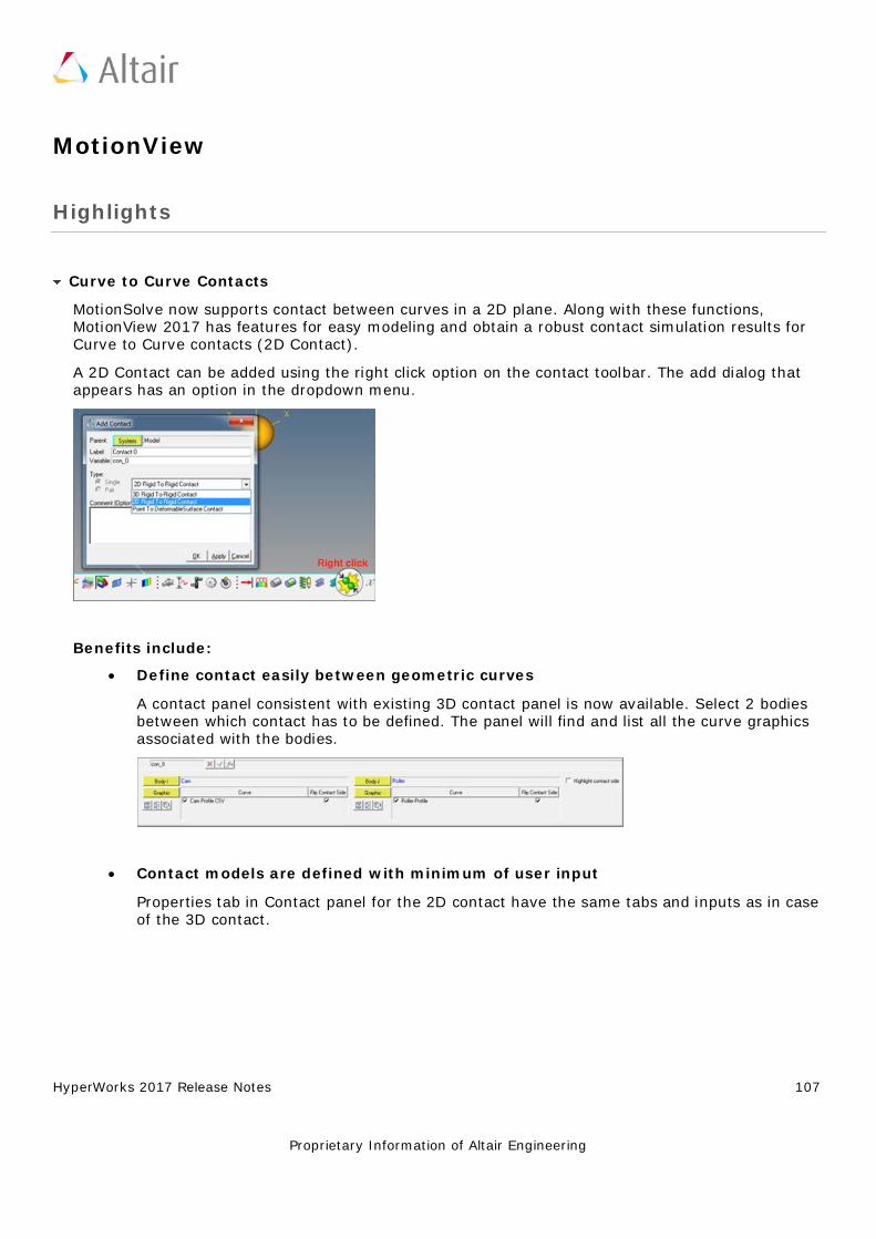
HyperWorks 2017 Release Notes 107
Proprietary Information of Altair Engineering
MotionView
Highlights
Curve to Curve Contacts
MotionSolve now supports contact between curves in a 2D plane. Along with these functions, MotionView 2017 has features for easy modeling and obtain a robust contact simulation results for Curve to Curve contacts (2D Contact).
A 2D Contact can be added using the right click option on the contact toolbar. The add dialog that appears has an option in the dropdown menu.
Benefits include:
• Define contact easily between geometric curves A contact panel consistent with existing 3D contact panel is now available. Select 2 bodies between which contact has to be defined. The panel will find and list all the curve graphics associated with the bodies.
• Contact models are defined with minimum of user input Properties tab in Contact panel for the 2D contact have the same tabs and inputs as in case of the 3D contact.
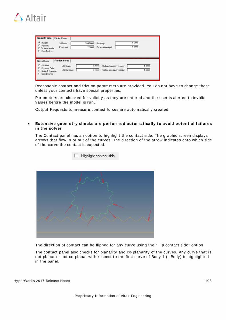
HyperWorks 2017 Release Notes 108
Proprietary Information of Altair Engineering
Reasonable contact and friction parameters are provided. You do not have to change these unless your contacts have special properties.
Parameters are checked for validity as they are entered and the user is alerted to invalid values before the model is run.
Output Requests to measure contact forces are automatically created.
• Extensive geometry checks are performed automatically to avoid potential failures in the solver The Contact panel has an option to highlight the contact side. The graphic screen displays arrows that flow in or out of the curves. The direction of the arrow indicates onto which side of the curve the contact is expected.
The direction of contact can be flipped for any curve using the “Flip contact side” option
The contact panel also checks for planarity and co-planarity of the curves. Any curve that is not planar or not co-planar with respect to the first curve of Body 1 (I Body) is highlighted in the panel.
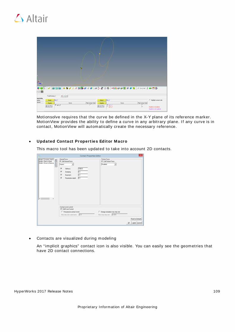
HyperWorks 2017 Release Notes 109
Proprietary Information of Altair Engineering
Motionsolve requires that the curve be defined in the X-Y plane of its reference marker. MotionView provides the ability to define a curve in any arbitrary plane. If any curve is in contact, MotionView will automatically create the necessary reference.
• Updated Contact Properties Editor Macro This macro tool has been updated to take into account 2D contacts.
• Contacts are visualized during modeling An “implicit graphics” contact icon is also visible. You can easily see the geometries that have 2D contact connections.
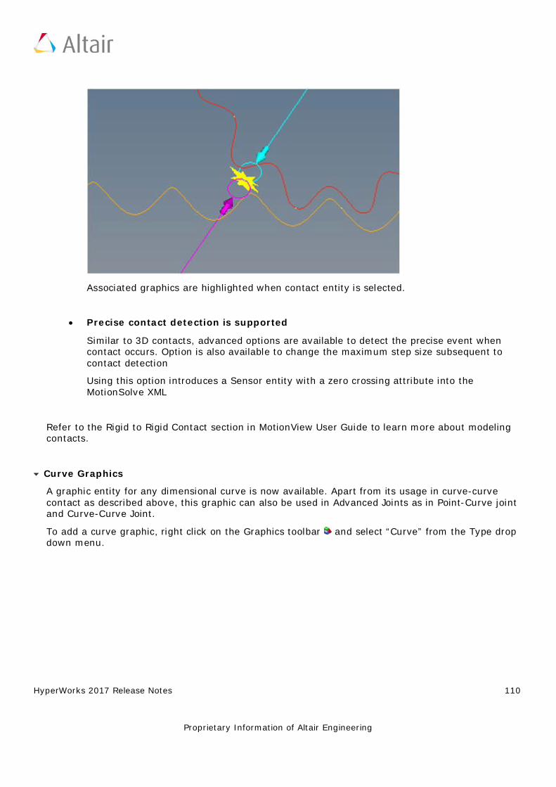
HyperWorks 2017 Release Notes 110
Proprietary Information of Altair Engineering
Associated graphics are highlighted when contact entity is selected.
• Precise contact detection is supported Similar to 3D contacts, advanced options are available to detect the precise event when contact occurs. Option is also available to change the maximum step size subsequent to contact detection
Using this option introduces a Sensor entity with a zero crossing attribute into the MotionSolve XML
Refer to the Rigid to Rigid Contact section in MotionView User Guide to learn more about modeling contacts.
Curve Graphics
A graphic entity for any dimensional curve is now available. Apart from its usage in curve-curve contact as described above, this graphic can also be used in Advanced Joints as in Point-Curve joint and Curve-Curve Joint.
To add a curve graphic, right click on the Graphics toolbar and select “Curve” from the Type drop down menu.
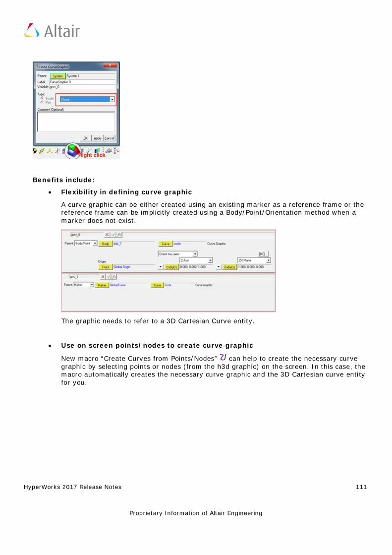
HyperWorks 2017 Release Notes 111
Proprietary Information of Altair Engineering
Benefits include:
• Flexibility in defining curve graphic A curve graphic can be either created using an existing marker as a reference frame or the reference frame can be implicitly created using a Body/Point/Orientation method when a marker does not exist.
The graphic needs to refer to a 3D Cartesian Curve entity.
• Use on screen points/nodes to create curve graphic
New macro “Create Curves from Points/Nodes” can help to create the necessary curve graphic by selecting points or nodes (from the h3d graphic) on the screen. In this case, the macro automatically creates the necessary curve graphic and the 3D Cartesian curve entity for you.
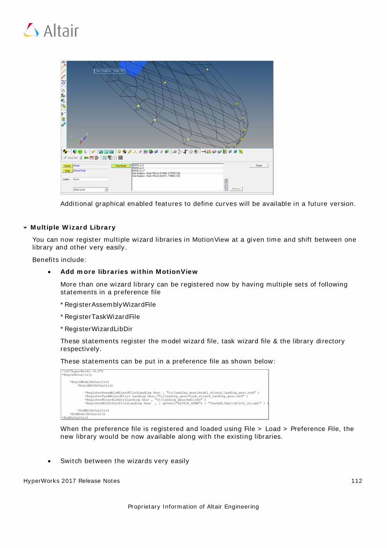
HyperWorks 2017 Release Notes 112
Proprietary Information of Altair Engineering
Additional graphical enabled features to define curves will be available in a future version.
Multiple Wizard Library
You can now register multiple wizard libraries in MotionView at a given time and shift between one library and other very easily.
Benefits include:
• Add more libraries within MotionView More than one wizard library can be registered now by having multiple sets of following statements in a preference file
*RegisterAssemblyWizardFile
*RegisterTaskWizardFile
*RegisterWizardLibDir
These statements register the model wizard file, task wizard file & the library directory respectively.
These statements can be put in a preference file as shown below:
When the preference file is registered and loaded using File > Load > Preference File, the new library would be now available along with the existing libraries.
• Switch between the wizards very easily
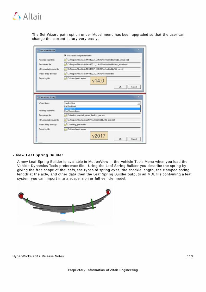
HyperWorks 2017 Release Notes 113
Proprietary Information of Altair Engineering
The Set Wizard path option under Model menu has been upgraded so that the user can change the current library very easily.
New Leaf Spring Builder
A new Leaf Spring Builder is available in MotionView in the Vehicle Tools Menu when you load the Vehicle Dynamics Tools preference file. Using the Leaf Spring Builder you describe the spring by giving the free shape of the leafs, the types of spring eyes, the shackle length, the clamped spring length at the axle, and other data then the Leaf Spring Builder outputs an MDL file containing a leaf system you can import into a suspension or full vehicle model.
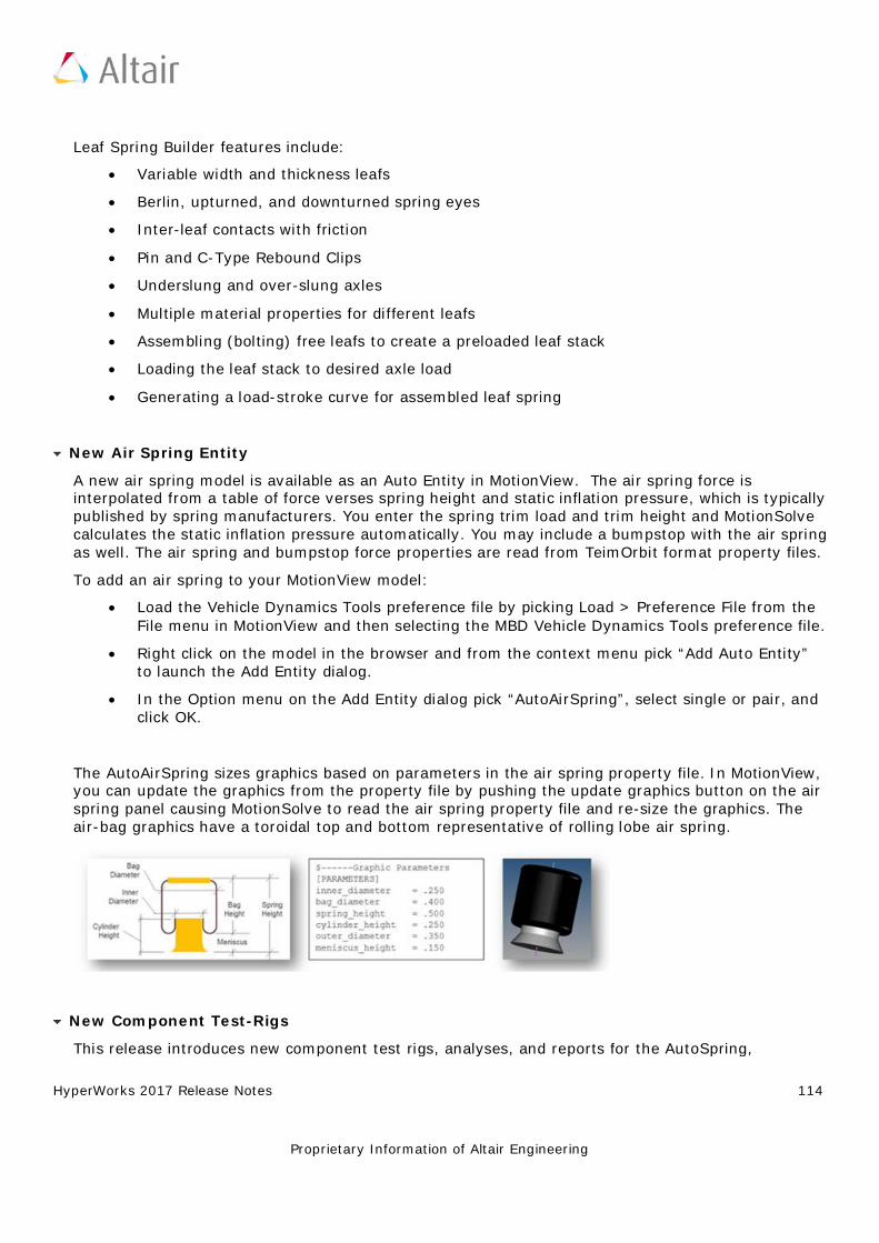
HyperWorks 2017 Release Notes 114
Proprietary Information of Altair Engineering
Leaf Spring Builder features include:
• Variable width and thickness leafs • Berlin, upturned, and downturned spring eyes • Inter-leaf contacts with friction • Pin and C-Type Rebound Clips • Underslung and over-slung axles • Multiple material properties for different leafs • Assembling (bolting) free leafs to create a preloaded leaf stack • Loading the leaf stack to desired axle load • Generating a load-stroke curve for assembled leaf spring
New Air Spring Entity
A new air spring model is available as an Auto Entity in MotionView. The air spring force is interpolated from a table of force verses spring height and static inflation pressure, which is typically published by spring manufacturers. You enter the spring trim load and trim height and MotionSolve calculates the static inflation pressure automatically. You may include a bumpstop with the air spring as well. The air spring and bumpstop force properties are read from TeimOrbit format property files.
To add an air spring to your MotionView model:
• Load the Vehicle Dynamics Tools preference file by picking Load > Preference File from the File menu in MotionView and then selecting the MBD Vehicle Dynamics Tools preference file.
• Right click on the model in the browser and from the context menu pick “Add Auto Entity” to launch the Add Entity dialog.
• In the Option menu on the Add Entity dialog pick “AutoAirSpring”, select single or pair, and click OK.
The AutoAirSpring sizes graphics based on parameters in the air spring property file. In MotionView, you can update the graphics from the property file by pushing the update graphics button on the air spring panel causing MotionSolve to read the air spring property file and re-size the graphics. The air-bag graphics have a toroidal top and bottom representative of rolling lobe air spring.
New Component Test-Rigs
This release introduces new component test rigs, analyses, and reports for the AutoSpring,
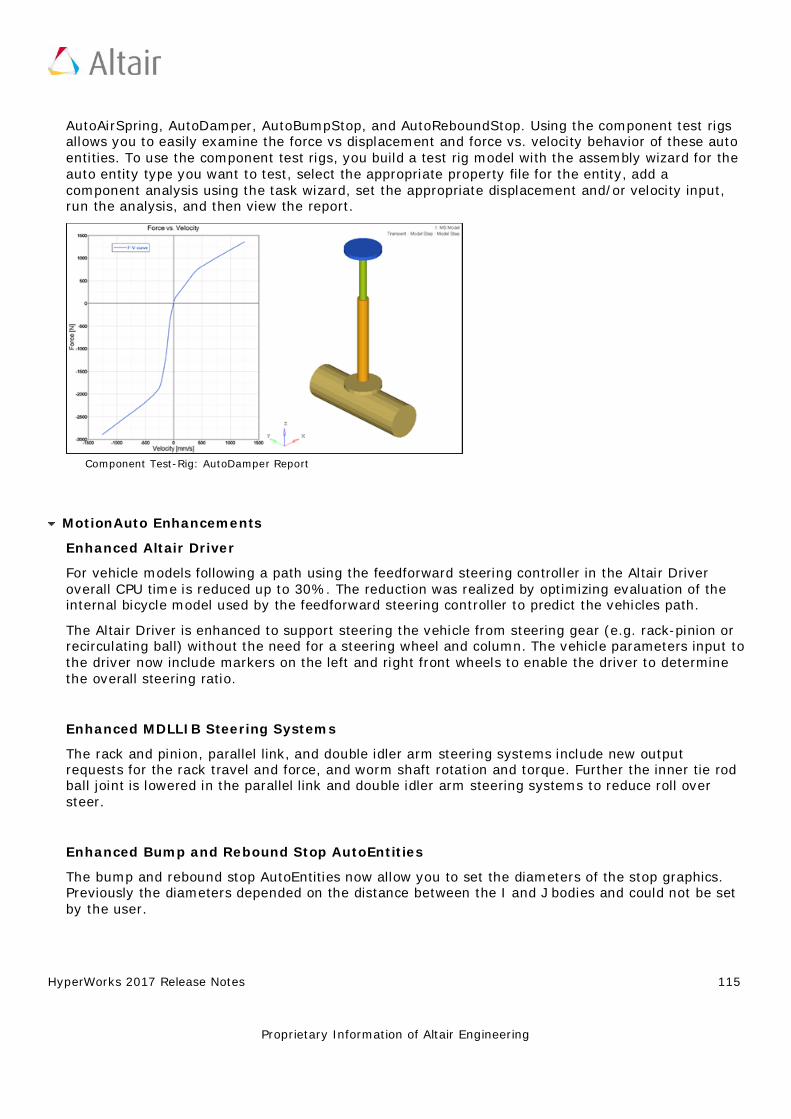
HyperWorks 2017 Release Notes 115
Proprietary Information of Altair Engineering
AutoAirSpring, AutoDamper, AutoBumpStop, and AutoReboundStop. Using the component test rigs allows you to easily examine the force vs displacement and force vs. velocity behavior of these auto entities. To use the component test rigs, you build a test rig model with the assembly wizard for the auto entity type you want to test, select the appropriate property file for the entity, add a component analysis using the task wizard, set the appropriate displacement and/or velocity input, run the analysis, and then view the report.
Component Test-Rig: AutoDamper Report
MotionAuto Enhancements
Enhanced Altair Driver
For vehicle models following a path using the feedforward steering controller in the Altair Driver overall CPU time is reduced up to 30%. The reduction was realized by optimizing evaluation of the internal bicycle model used by the feedforward steering controller to predict the vehicles path.
The Altair Driver is enhanced to support steering the vehicle from steering gear (e.g. rack-pinion or recirculating ball) without the need for a steering wheel and column. The vehicle parameters input to the driver now include markers on the left and right front wheels to enable the driver to determine the overall steering ratio.
Enhanced MDLLIB Steering Systems
The rack and pinion, parallel link, and double idler arm steering systems include new output requests for the rack travel and force, and worm shaft rotation and torque. Further the inner tie rod ball joint is lowered in the parallel link and double idler arm steering systems to reduce roll over steer.
Enhanced Bump and Rebound Stop AutoEntities
The bump and rebound stop AutoEntities now allow you to set the diameters of the stop graphics. Previously the diameters depended on the distance between the I and J bodies and could not be set by the user.
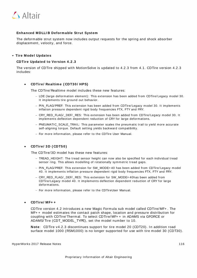
HyperWorks 2017 Release Notes 116
Proprietary Information of Altair Engineering
Enhanced MDLLIB Deformable Strut System
The deformable strut system now includes output requests for the spring and shock absorber displacement, velocity, and force.
Tire Model Updates
CDTire Updated to Version 4.2.3
The version of CDTire shipped with MotionSolve is updated to 4.2.3 from 4.1. CDTire version 4.2.3 includes:
• CDTire/Realtime (CDT30/HPS) The CDTire/Realtime model includes these new features:
− LDE (large deformation element): This extension has been added from CDTire/Legacy model 30. It implements tire ground out behavior.
− PIN_FLAG/PREF: This extension has been added from CDTire/Legacy model 30. It implements inflation pressure dependent rigid body frequencies FTX, FTY and FRY.
− CRY_RED_FLAG/_DEF/_RES: This extension has been added from CDTire/Legacy model 30. It implements deflection dependent reduction of CRY for large deformations.
− PNEUMATIC_SCALE_TRAIL: This parameter scales the pneumatic trail to yield more accurate self-aligning torque. Default setting yields backward compatibility.
− For more information, please refer to the CDTire User Manual.
• CDTire/3D (CDT50) The CDTire/3D model has these new features:
− TREAD_HEIGHT: The tread sensor height can now also be specified for each individual tread sensor ring. This allows modelling of rotationally symmetric tread gaps.
− PIN_FLAG/PREF: This extension for SW_MODE=40 has been added from CDTire/Legacy model 40. It implements inflation pressure dependent rigid body frequencies FTX, FTY and FRY.
− CRY_RED_FLAG/_DEF/_RES: This extension for SW_MODE=40has been added from CDTire/Legacy model 40. It implements deflection dependent reduction of CRY for large deformations.
− For more information, please refer to the CDTireUser Manual.
• CDTire/MF++ CDTire version 4.2 introduces a new Magic Formula sub model called CDTire/MF+. The MF++ model estimates the contact patch shape, location and pressure distribution for coupling with CDTire/Thermal. To select CDTire/MF++ in ADAMS via GFORCE or ADAMS/Tire (CDT_MODEL_TYPE), set the model number to 10.
Note: CDTire v4.2.3 discontinues support for tire model 20 (CDT20). In addition road surface model 1000 (RSM1000) is no longer supported for use with tire model 30 (CDT30).
HyperWorks 2017 Release Notes 117
Proprietary Information of Altair Engineering
FTIRE
MotionSolve now locates your FTIRE installation by reading the cosin_ini file in your home directory. This ensures MotionSolve uses the latest version of FTIRE installed. Previously, FTIRE binaries were shipped with MotionSolve and MotionSolve loaded FTIRE from the HyperWorks installation.
Note: If you previously used FTIRE via Altair’s Partner’s Program, you must now obtain FTIRE from COSIN (www.cosin.eu)
Delft-Tyre MF-TYRE/MF-SWIFT
DELFT-TYRE MF-Tyre/MF-Swift 6.2.0.2 binaries are included with MotionSolve version 2017. Use of MF-Tyre with MotionView and MotionSolve is granted under the HyperWorks license. Use of MF-Swift require purchase of an additional license available from Altair.
Resolved Issues
MotionView memory usage is improved. In earlier versions, MotionView would accumulate memory on repeated loading of models. While an increase in memory usage is still observed for the initial 3 to 6 models opened, the memory usage stabilizes with further loading.
The help link for (Advanced) Altair Driver panel in MotionView is updated to point to the correct location in the online help.
In models containing AutoCDTire and AutoCTITire (FTIRE) entities, MotionView crashed when exporting the model to Adams. The definitions for AutoCDTire and AutoCTITire are updated to correct the issue.
HyperWorks 2017 Release Notes 118
Proprietary Information of Altair Engineering
Multibody Solutions
Highlights
The Altair multibody solution, MotionSolve, consists of the following capabilities:
• MotionView – the modeling environment • MotionSolve – the solver • Automotive Solutions – for suspension design, vehicle dynamics, ride comfort and durability • HyperGraph/HyperView – the post-processing environment
The 2017 release of MotionSolve contains the following major capabilities that span the breadth of the multibody solution – modeling, simulation and post-processing.
• Curve-Curve (2D) Contacts • Leaf Spring builder • Air Spring • Component Test Rig and Analyses
Curve to Curve Contacts
The 2017 release of MotionSolve enables you to define rigid body contact between two curves that are each defined in two dimensions. Simulating rigid body contact in two dimensions between two curves is advantageous when:
• It is known a-priori that the contact occurs only within the plane in which the two curves are defined i.e. there are no out-of-plane contact forces that are expected.
• The curves between which the contact is to be calculated are smooth and represent the curvature of the 3D geometry well
The advantages of simulating rigid body contact using 2D curves over 3D tessellated geometry are many:
• More accurate results: Results are more accurate since there is lesser error due to discretization. Discretization of a 3D geometry into triangles occurs over 3 dimensions as opposed to 2 in curves
• Easily improve accuracy: Accuracy of the results can be improved quicker by introducing more points in the curve within MotionView.
• Improving the accuracy of results when using 3D contact requires you to re-import the graphic and re-mesh or go outside the MotionView environment into a CAD tool to re-mesh. Re-meshing a 3D geometry will certainly take more time than refining a 2D curve.
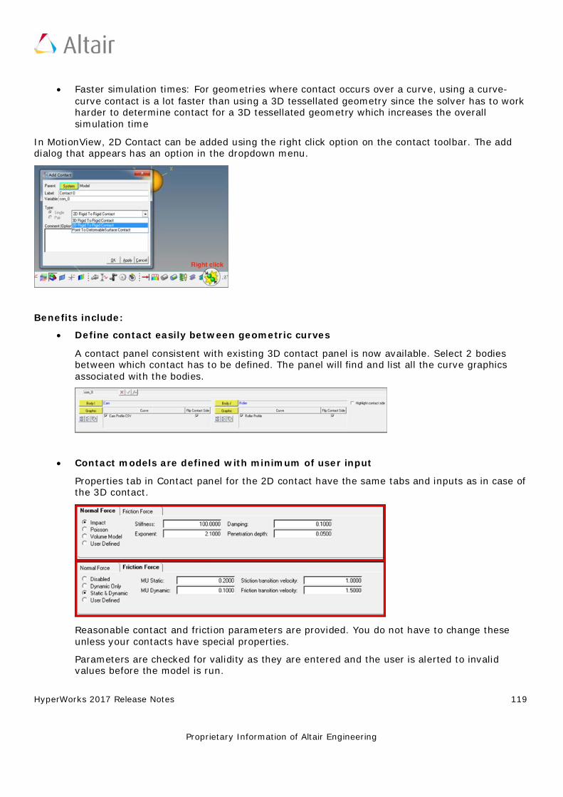
HyperWorks 2017 Release Notes 119
Proprietary Information of Altair Engineering
• Faster simulation times: For geometries where contact occurs over a curve, using a curve-curve contact is a lot faster than using a 3D tessellated geometry since the solver has to work harder to determine contact for a 3D tessellated geometry which increases the overall simulation time
In MotionView, 2D Contact can be added using the right click option on the contact toolbar. The add dialog that appears has an option in the dropdown menu.
Benefits include:
• Define contact easily between geometric curves A contact panel consistent with existing 3D contact panel is now available. Select 2 bodies between which contact has to be defined. The panel will find and list all the curve graphics associated with the bodies.
• Contact models are defined with minimum of user input Properties tab in Contact panel for the 2D contact have the same tabs and inputs as in case of the 3D contact.
Reasonable contact and friction parameters are provided. You do not have to change these unless your contacts have special properties.
Parameters are checked for validity as they are entered and the user is alerted to invalid values before the model is run.
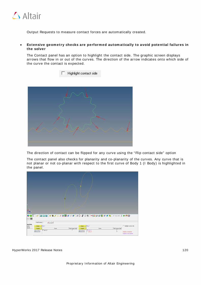
HyperWorks 2017 Release Notes 120
Proprietary Information of Altair Engineering
Output Requests to measure contact forces are automatically created.
• Extensive geometry checks are performed automatically to avoid potential failures in the solver The Contact panel has an option to highlight the contact side. The graphic screen displays arrows that flow in or out of the curves. The direction of the arrow indicates onto which side of the curve the contact is expected.
The direction of contact can be flipped for any curve using the “Flip contact side” option
The contact panel also checks for planarity and co-planarity of the curves. Any curve that is not planar or not co-planar with respect to the first curve of Body 1 (I Body) is highlighted in the panel.
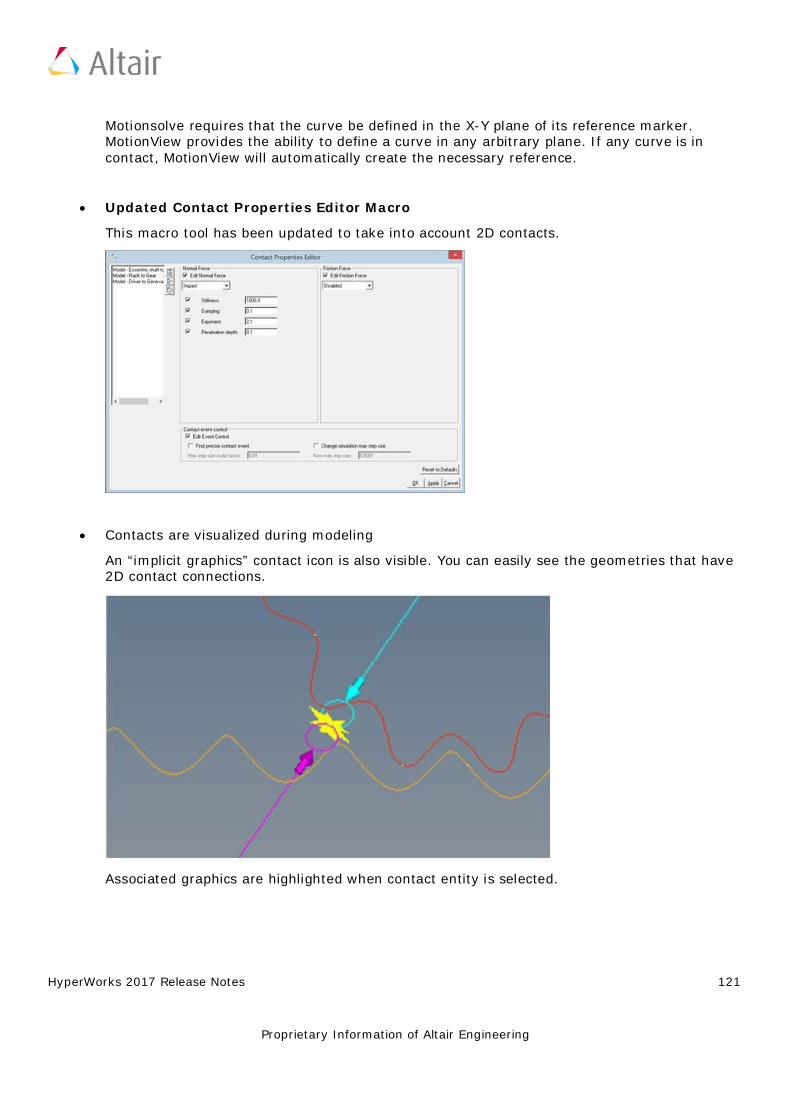
HyperWorks 2017 Release Notes 121
Proprietary Information of Altair Engineering
Motionsolve requires that the curve be defined in the X-Y plane of its reference marker. MotionView provides the ability to define a curve in any arbitrary plane. If any curve is in contact, MotionView will automatically create the necessary reference.
• Updated Contact Properties Editor Macro This macro tool has been updated to take into account 2D contacts.
• Contacts are visualized during modeling An “implicit graphics” contact icon is also visible. You can easily see the geometries that have 2D contact connections.
Associated graphics are highlighted when contact entity is selected.

HyperWorks 2017 Release Notes 122
Proprietary Information of Altair Engineering
• Precise contact detection is supported Similar to 3D contacts, advanced options are available to detect the precise event when contact occurs. Option is also available to change the maximum step size subsequent to contact detection
Using this option introduces a Sensor entity with a zero crossing attribute into the MotionSolve XML
For more details on how curve-curve contact can be defined and solved, refer to Rigid to Rigid Contact section in MotionView User Guide and Modeling Contacts in MotionSolve User Guide.
Curve Graphics
A graphic entity for any dimensional curve is now available. Apart from its usage in curve-curve contact as described above, this graphic can also be used in Advanced Joints as in Point-Curve joint and Curve-Curve Joint.
To add a curve graphic, right click on the Graphics toolbar and select “Curve” from the Type drop down menu.
Benefits include:
• Flexibility in defining curve graphic A curve graphic can be either created using an existing marker as a reference frame or the reference frame can be implicitly created using a Body/Point/Orientation method when a marker does not exist.
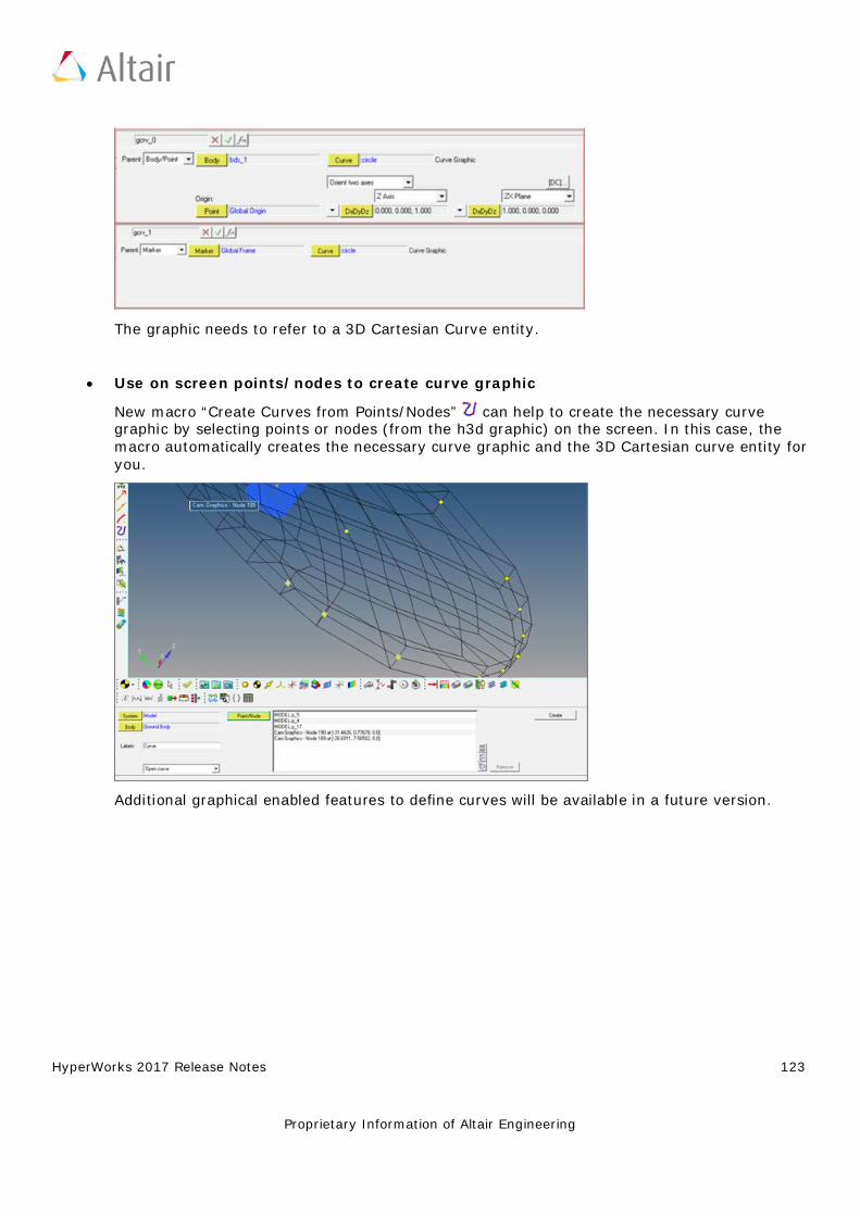
HyperWorks 2017 Release Notes 123
Proprietary Information of Altair Engineering
The graphic needs to refer to a 3D Cartesian Curve entity.
• Use on screen points/nodes to create curve graphic
New macro “Create Curves from Points/Nodes” can help to create the necessary curve graphic by selecting points or nodes (from the h3d graphic) on the screen. In this case, the macro automatically creates the necessary curve graphic and the 3D Cartesian curve entity for you.
Additional graphical enabled features to define curves will be available in a future version.
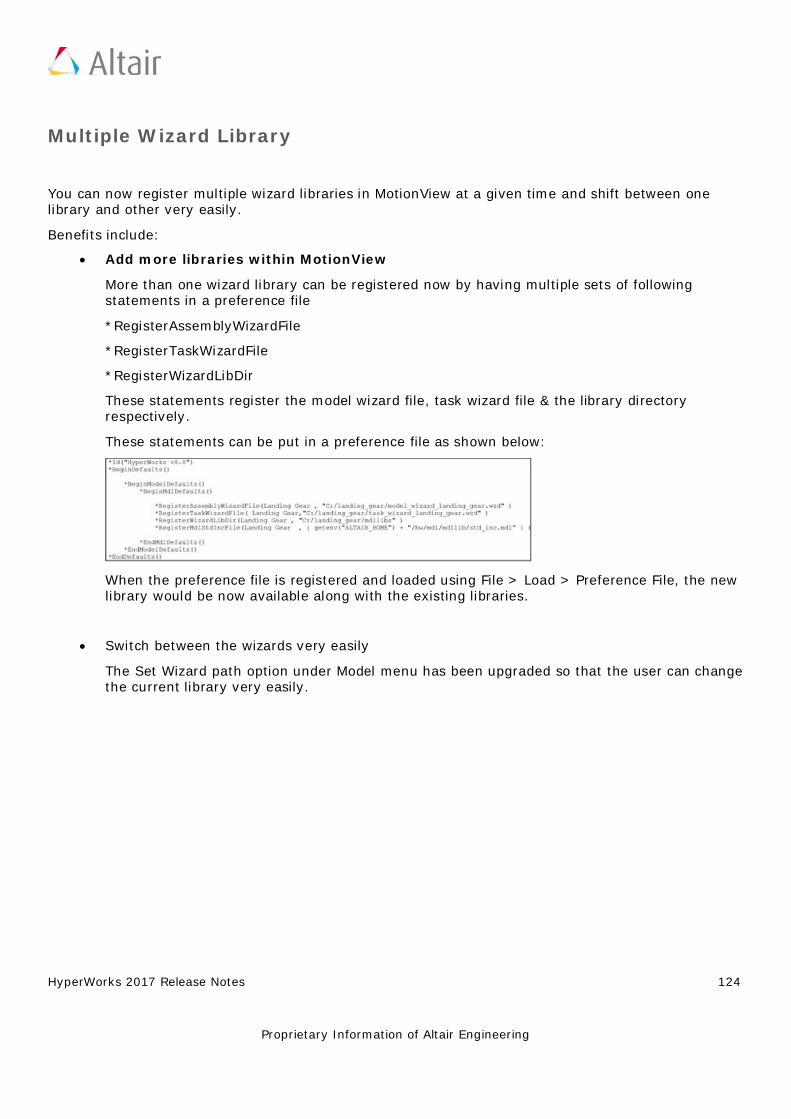
HyperWorks 2017 Release Notes 124
Proprietary Information of Altair Engineering
Multiple Wizard Library
You can now register multiple wizard libraries in MotionView at a given time and shift between one library and other very easily.
Benefits include:
• Add more libraries within MotionView More than one wizard library can be registered now by having multiple sets of following statements in a preference file
*RegisterAssemblyWizardFile
*RegisterTaskWizardFile
*RegisterWizardLibDir
These statements register the model wizard file, task wizard file & the library directory respectively.
These statements can be put in a preference file as shown below:
When the preference file is registered and loaded using File > Load > Preference File, the new library would be now available along with the existing libraries.
• Switch between the wizards very easily The Set Wizard path option under Model menu has been upgraded so that the user can change the current library very easily.
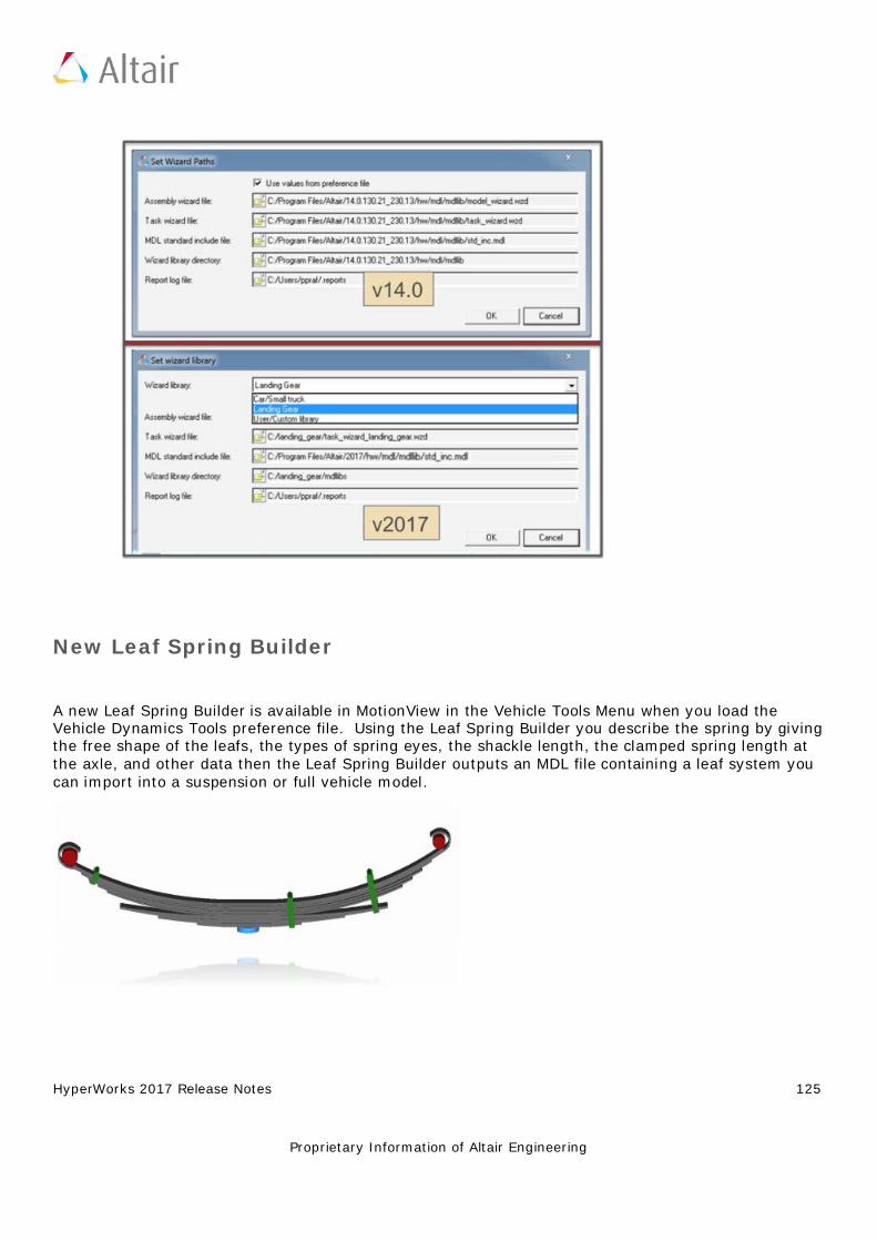
HyperWorks 2017 Release Notes 125
Proprietary Information of Altair Engineering
New Leaf Spring Builder
A new Leaf Spring Builder is available in MotionView in the Vehicle Tools Menu when you load the Vehicle Dynamics Tools preference file. Using the Leaf Spring Builder you describe the spring by giving the free shape of the leafs, the types of spring eyes, the shackle length, the clamped spring length at the axle, and other data then the Leaf Spring Builder outputs an MDL file containing a leaf system you can import into a suspension or full vehicle model.
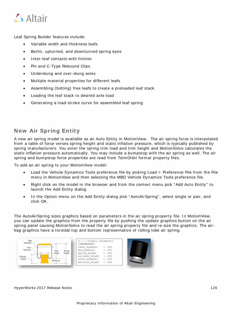
HyperWorks 2017 Release Notes 126
Proprietary Information of Altair Engineering
Leaf Spring Builder features include:
• Variable width and thickness leafs • Berlin, upturned, and downturned spring eyes • Inter-leaf contacts with friction • Pin and C-Type Rebound Clips • Underslung and over-slung axles • Multiple material properties for different leafs • Assembling (bolting) free leafs to create a preloaded leaf stack • Loading the leaf stack to desired axle load • Generating a load-stroke curve for assembled leaf spring
New Air Spring Entity A new air spring model is available as an Auto Entity in MotionView. The air spring force is interpolated from a table of force verses spring height and static inflation pressure, which is typically published by spring manufacturers. You enter the spring trim load and trim height and MotionSolve calculates the static inflation pressure automatically. You may include a bumpstop with the air spring as well. The air spring and bumpstop force properties are read from TeimOrbit format property files.
To add an air spring to your MotionView model:
• Load the Vehicle Dynamics Tools preference file by picking Load > Preference File from the File menu in MotionView and then selecting the MBD Vehicle Dynamics Tools preference file.
• Right click on the model in the browser and from the context menu pick “Add Auto Entity” to launch the Add Entity dialog.
• In the Option menu on the Add Entity dialog pick “AutoAirSpring”, select single or pair, and click OK.
The AutoAirSpring sizes graphics based on parameters in the air spring property file. In MotionView, you can update the graphics from the property file by pushing the update graphics button on the air spring panel causing MotionSolve to read the air spring property file and re-size the graphics. The air-bag graphics have a toroidal top and bottom representative of rolling lobe air spring.
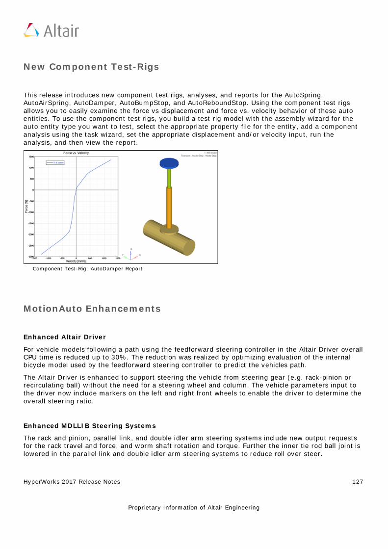
HyperWorks 2017 Release Notes 127
Proprietary Information of Altair Engineering
New Component Test-Rigs
This release introduces new component test rigs, analyses, and reports for the AutoSpring, AutoAirSpring, AutoDamper, AutoBumpStop, and AutoReboundStop. Using the component test rigs allows you to easily examine the force vs displacement and force vs. velocity behavior of these auto entities. To use the component test rigs, you build a test rig model with the assembly wizard for the auto entity type you want to test, select the appropriate property file for the entity, add a component analysis using the task wizard, set the appropriate displacement and/or velocity input, run the analysis, and then view the report.
Component Test-Rig: AutoDamper Report
MotionAuto Enhancements
Enhanced Altair Driver
For vehicle models following a path using the feedforward steering controller in the Altair Driver overall CPU time is reduced up to 30%. The reduction was realized by optimizing evaluation of the internal bicycle model used by the feedforward steering controller to predict the vehicles path.
The Altair Driver is enhanced to support steering the vehicle from steering gear (e.g. rack-pinion or recirculating ball) without the need for a steering wheel and column. The vehicle parameters input to the driver now include markers on the left and right front wheels to enable the driver to determine the overall steering ratio.
Enhanced MDLLIB Steering Systems
The rack and pinion, parallel link, and double idler arm steering systems include new output requests for the rack travel and force, and worm shaft rotation and torque. Further the inner tie rod ball joint is lowered in the parallel link and double idler arm steering systems to reduce roll over steer.
HyperWorks 2017 Release Notes 128
Proprietary Information of Altair Engineering
Enhanced Bump and Rebound Stop AutoEntities
The bump and rebound stop AutoEntities now allow you to set the diameters of the stop graphics. Previously the diameters depended on the distance between the I and J bodies and could not be set by the user.
Enhanced MDLLIB Deformable Strut System
The deformable strut system now includes output requests for the spring and shock absorber displacement, velocity, and force.
Tire Model Updates
CDTire Updated to Version 4.2.3
The version of CDTire shipped with MotionSolve is updated to 4.2.3 from 4.1. CDTire version 4.2.3 includes:
• CDTire/Realtime (CDT30/HPS) The CDTire/Realtime model includes these new features:
− LDE (large deformation element): This extension has been added from CDTire/Legacy model 30. It implements tire ground out behavior.
− PIN_FLAG/PREF: This extension has been added from CDTire/Legacy model 30. It implements inflation pressure dependent rigid body frequencies FTX, FTY and FRY.
− CRY_RED_FLAG/_DEF/_RES: This extension has been added from CDTire/Legacy model 30. It implements deflection dependent reduction of CRY for large deformations.
− PNEUMATIC_SCALE_TRAIL: This parameter scales the pneumatic trail to yield more accurate self-aligning torque. Default setting yields backward compatibility.
− For more information, please refer to the CDTire User Manual.
• CDTire/3D (CDT50) The CDTire/3D model has these new features:
− TREAD_HEIGHT: The tread sensor height can now also be specified for each individual tread sensor ring. This allows modelling of rotationally symmetric tread gaps.
− PIN_FLAG/PREF: This extension for SW_MODE=40 has been added from CDTire/Legacy model 40. It implements inflation pressure dependent rigid body frequencies FTX, FTY and FRY.
− CRY_RED_FLAG/_DEF/_RES: This extension for SW_MODE=40has been added from CDTire/Legacy model 40. It implements deflection dependent reduction of CRY for large deformations.
− For more information, please refer to the CDTireUser Manual.
HyperWorks 2017 Release Notes 129
Proprietary Information of Altair Engineering
• CDTire/MF++ CDTire version 4.2 introduces a new Magic Formula sub model called CDTire/MF+. The MF++ model estimates the contact patch shape, location and pressure distribution for coupling with CDTire/Thermal. To select CDTire/MF++ in ADAMS via GFORCE or ADAMS/Tire (CDT_MODEL_TYPE), set the model number to 10.
Note: CDTire v4.2.3 discontinues support for tire model 20 (CDT20). In addition road surface model 1000 (RSM1000) is no longer supported for use with tire model 30 (CDT30).
FTIRE
MotionSolve now locates your FTIRE installation by reading the cosin_ini file in your home directory. This ensures MotionSolve uses the latest version of FTIRE installed. Previously, FTIRE binaries were shipped with MotionSolve and MotionSolve loaded FTIRE from the HyperWorks installation.
Note: If you previously used FTIRE via Altair’s Partner’s Program, you must now obtain FTIRE from COSIN (www.cosin.eu)
Delft-Tyre MF-TYRE/MF-SWIFT
DELFT-TYRE MF-Tyre/MF-Swift 6.2.0.2 binaries are included with MotionSolve version 2017. Use of MF-Tyre with MotionView and MotionSolve is granted under the HyperWorks license. Use of MF-Swift require purchase of an additional license available from Altair.
Resolved Issues
MotionView memory usage is improved. In earlier versions, MotionView would accumulate memory on repeated loading of models. While an increase in memory usage is still observed for the initial 3 to 6 models opened, the memory usage stabilizes with further loading.
The help link for (Advanced) Altair Driver panel in MotionView is updated to point to the correct location in the online help.
In models containing AutoCDTire and AutoCTITire (FTIRE) entities, MotionView crashed when exporting the model to Adams. The definitions for AutoCDTire and AutoCTITire are updated to correct the issue.
Failure in Quasi-static analysis
Previously for models that contained massless bodies and ran quasi-static analysis, a simulation failure occurred on the last step of analysis independent of the simulation end time. The simulation failure no longer occurs.
HyperWorks 2017 Release Notes 130
Proprietary Information of Altair Engineering
OptiStruct
Highlights
Altair OptiStruct is an industry proven, modern structural analysis solver for linear and non-linear mechanical problems under static, dynamic, and thermal loads. It is the market-leading solution for structural design and optimization. Based on finite-element and multi-body dynamics technology, and through advanced analysis and optimization algorithms, OptiStruct helps designers and engineers rapidly develop innovative, lightweight and structurally efficient designs. OptiStruct is used by thousands of companies worldwide to analyze and optimize structures and mechanical systems for strength, durability, noise and vibrations, heat transfer, as well as impact.
The major items for the 2017 release are:
• Puck Failure Criteria • Inertia Relief for models with greater than 6 rigid body modes. • User-defined material (beta) • Friction table support for Nonlinear Analysis • Material Coordinate System for Solid Elements • Complex Eigenvalue Analysis for Acoustics • Power output for Heat Transfer (SPCFORCE) • 64-bit OptiStruct support (Beta)
In addition to the OptiStruct 2017 Release Notes, this document also contains a list of all features released after OptiStruct 14.0. The version in which a particular feature was released can be determined by looking at the corresponding version number in parentheses.
In this Release
Stiffness, Strength and Stability Noise and Vibrations Thermal Analysis Multiphysics General Updates Optimization
Solvers 3rd Party Interface Resolved Issues
HyperWorks 2017 Release Notes 131
Proprietary Information of Altair Engineering
Stiffness, Strength and Stability
Puck Failure Criteria (2017)
Composite Puck Failure Criteria are now available for output via the CFAILURE I/O Options entry for Static, Normal Modes, and Transient Analysis. The MATF Bulk Data Entry is introduced to specify the PUCK failure model properties. This feature is currently only supported for analysis (optimization support will be added in a subsequent release).
Enhanced Support for Nonlinear Restart (2017)
Nonlinear Restart is now supported for Large Displacement Nonlinear Transient Analysis, Bolt Pretension, and Inertia Relief. The RESTARTR and RESTARTW I/O Options Entries can be used to activate Nonlinear Restart capabilities.
Stress and Damage History Output for Fatigue Analysis (2017)
Mean Stress, Stress Amplitude, and corresponding Damage at every cycle is output for Fatigue Analysis via the RNFLOW I/O Option. The output is printed in .rnf files.
Lagrange Multiplier Method for RIGID CBUSH Elements (2017)
A new Lagrange multiplier method is available for rigid CBUSH elements via SYSSETTING(PBUSHFORM=LAG) I/O Options entry. The previous penalty formulation is the default and can also be explicitly activated using SYSSETTING(PBUSHFORM=PEN) I/O Options entry.
Random Response Fatigue Analysis (2017)
Fatigue Analysis based on Random Response Analysis is now supported. The LCID field on the FATLOAD Bulk Data entry can reference the subcase ID of a Random Response Subcase. The RDMGMDL continuation line on the FATPARM Bulk Data entry can be used to specify Random Response Damage models. The RANDOM continuation line on the FATPARM entry can be used to define other parameters for Random Response Fatigue. The damage/life results can be evaluated for shells/solids, spot welds and seam welds. This feature is currently only supported for analysis (optimization support will be added in a subsequent release).
CVISC and CDAMP support for Nonlinear Transient (2017)
CVISC and CDAMP Bulk Data entries are now supported for Direct Nonlinear Transient Analysis.
Convergence Plot for Nonlinear Static Analysis (2017)
Simple plots for nonlinear runs can be viewed during runtime using the Graph button in the HWSolver Run Manager Window. The plots contain all nonlinear iterations across all subcases.
HyperWorks 2017 Release Notes 132
Proprietary Information of Altair Engineering
Inertia Relief for the Model that has More Than 6 Rigid Body Modes (2017)
Inertia Relief is now supported for the model with more than six rigid body modes via PARAM, INREL, -2, METHOD. The METHOD option references the ID of corresponding EIGRL or EIGRA entry. Models with mechanisms may have more than six rigid body modes.
User-Defined Material Support - Beta (2017)
User-defined Material is now supported via the MATUSR Bulk Data entry. The LOADLIB I/O Options Entry can be used to identify the user-defined material file (both Win64 and Linux64). Currently, only solid elements are supported.
Friction Table for Contact (2017)
The MU1 field on the PCONT Bulk Data entry can reference a TABLES1 entry to define a friction table based on pseudo time of the current nonlinear increment. This will allow the user to specify time-dependent friction.
MPC, Rigid Elements in GROUNDCHECK (2017)
MPC’s and Rigid elements are now included in the grounding check when using the GROUNDCHECK Subcase entry.
Follower Loading is Default for Pressure Loads (2017)
Pressure loads are now follower loads by default.
Material Coordinate System (CORDM) for Solids are now Available for Elements (2017)
The CORDM continuation line is now available on all solid elements to define material coordinate system directly on the element Bulk Data entries. CORDM was only available in PSOLID up to previous release. It is now also available in solid element entries.
Restart for Nonlinear Analysis (14.0.230)
Restart (save results and retrieve for restart) is now available for nonlinear analysis.
Debugging Utility for Nonlinear Analysis (14.0.230)
With new option added as PARAM,NLMON or subcase selector NLMON, the displacement results for each iteration will be available in the _nl.h3d file while the job is running. This is available for both small and large displacement analysis.
NLMON will also Output Useful Diagnostic Data (Max Residual Force and so on) in .out file for Large Displacement Analysis (14.0.230)
With TCL script provided in installation, the script will parse the .out file and help the user identify
HyperWorks 2017 Release Notes 133
Proprietary Information of Altair Engineering
which nodes have convergence issues.
Finite Sliding with CONSLI now Supports Smoothing Option (14.0.230)
SMOOTH option on CONTACT is now supported for Finite Sliding with CONSLI option.
Both Sides of Surface Results Available for Surface-to-Surface Contact (14.0.230)
Both Master and Slave side of results are available for surface-to-surface contact.
DOFs Selection for MPC Based TIE Contact (14.0.230)
The user can now choose DOFs to be constrained for MPC based TIE contact.
Enhanced Performance with Multiple Processors (14.0.230)
Some of the calculation for nonlinear analysis is sped up with OpenMP implementation. The performance benefit would be seen in large displacement analysis or the nonlinear material with plasticity.
DIRECT Option Available in NLADAPT (14.0.230)
With DIRECT option on NLADAPT, the user can choose fix time step for Large Displacement Analysis instead of dynamic time step schema.
CELAS in Large Displacement Analysis (14.0.230)
CELAS is now supported in Large Displacement Nonlinear Analysis.
Material Stability Check for Hyper Elasticity (14.0.230)
The results of stability check is available in the .out file. Such output can be turned off with PARAM,CHECKMAT,NO.
PLOAD/PLOAD2 as Follower Forces (14.0.230)
PLOAD, PLOAD2 entries are now supported as Follower Forces in Large Displacement Nonlinear Analysis.
New Finite Sliding Option (Continuous Sliding) has been Added (14.0.220)
With this option (TRACK=CONSLI on CONTACT bulk entry), the contact search is conducted for every nonlinear iteration. Continuous sliding contact is expected to produce more accurate results and better convergence robustness for some cases, especially when very large sliding and/or distortion are presented.
HyperWorks 2017 Release Notes 134
Proprietary Information of Altair Engineering
OLOAD Support for Incremental Results Output (NLOUT) in Nonlinear Analysis (14.0.220)
OLOAD support for Incremental Results output (NLOUT) in Nonlinear Analysis.
Inertia Relief Support for Large Displacement Analysis (14.0.220)
Inertia Relief support for large displacement Analysis.
GENER/DAMPER Option Support for PBUSH1D (14.0.220)
GENER/DAMPER option support for PBUSH1D.
Surface-to-Surface Discretization becomes Default for TIE/CONTACT with FREEZE when the Salve is not a Set of Grids and No Heat Transfer Subcase is Involved. (14.0.220)
Surface-to-Surface discretization becomes default for TIE/CONTACT with FREEZE when the salve is not a set of grids and no heat transfer subcase is involved.
ADJUST for TIE or CONTACT with FREEZE Now Accounts for Thickness Padding (GPAD) (14.0.220)
ADJUST for TIE or CONTACT with FREEZE now accounts for thickness padding (GPAD).
Removing/Re-activation of Elements is Now Supported for Small Displacement Nonlinear Analysis (14.0.220)
Removing/Re-activation of elements is now supported for small displacement nonlinear analysis.
Contact Area for Node-to-Surface Contact is Available (14.0.220)
Contact Area for Node-to-Surface contact is available.
Shell Elements are Now Supported for Large Displacement Nonlinear Static Analysis (14.0.210)
Shell Elements are now supported for Large Displacement Nonlinear Static Analysis. This is supported for shell elements with PSHELL Property and MAT1 and MATS1 Material entries.
Structural Nonlinear Transient Analysis (14.0.210)
Structural Nonlinear Transient Analysis is now available. It supports Nonlinear Contact, Material, and Geometry. Two time-stepping schemes are currently supported: Generalized Alpha Method (default) and the Backward Euler Method. Structural Nonlinear Transient Analysis is supported only with large displacement theory, therefore, PARAM,LGDISP,1 is required. The NLPARM or TSTEPNL entry can be used in a subcase to provide nonlinear parameters and convergence tolerances. The NLADAPT entries can also be used to define parameters for time-stepping and convergence criteria.
HyperWorks 2017 Release Notes 135
Proprietary Information of Altair Engineering
Nonlinear Material Support for Preloading and the Buckling Analysis (14.0.210)
Nonlinear materials (MATS1, MGASK, MATHE bulk data entries) and nonlinear bushing elements (KN option on PBUSH/PBUSH1D bulk data entries) are now supported for Preloading and Buckling analysis.
Node-to-Surface Contact with Friction Support for Preloading (14.0.210)
Node-to-Surface contact (DISCRET=N2S on CONTACT/TIE bulk data entries) with friction is now supported for Preloading analysis.
Retain Deformed Boundary for Multiple Continued Nonlinear Subcases (14.0.210)
Certain displacement from preceding nonlinear subcase can be carried over to the subsequent nonlinear subcase. Such displacement is applied as if an enforced displacement is applied in subsequent nonlinear subcase. The D field on the SPC and SPCD entries can be set to F in conjunction with the CNTNLSUB entry to retain the deformed boundary resulting from a preceding nonlinear subcase.
Bushing (CBUSH) Element Support for Nonlinear Large Displacement Analysis (14.0.210)
CBUSH elements in a large displacement Nonlinear analysis are now resolved using Large Displacement Theory. Previously, CBUSH elements were supported using Small Displacement Theory in Large Displacement Nonlinear analysis.
Non-convergent Solution Output for Large Displacement Nonlinear Analysis (14.0.210)
The SVNONCNV flag on the NLOUT entry to output non-convergent solution for incremental loading results is now available for Large Displacement Nonlinear Analysis.
The Ogden Material Model for Hyperelastic Materials is now Available (14.0.210)
The Ogden Material Model for Hyperelastic Materials is now available on the MATHE entry. The Model field can be set to OGDEN to activate Ogden Materials on the MATHE Bulk Data Entry.
Neuber Stress and Strain Output in Linear Analysis (14.0.210)
Neuber stress/strain is available in H3D format by adding the NEUBER keyword on the STRESS/STRAIN I/O Options Entry. Neuber corrected stresses and strains are calculated based on the Von Mises stresses from linear elastic analysis, the Young’s modulus and the nonlinear material property defined on the MATS1 entry.
Subcase Dependent Model Change with Regard to Contact Interfaces and Elements (14.0.210)
Contact Interfaces or Elements can be added or removed for different nonlinear static subcases in
HyperWorks 2017 Release Notes 136
Proprietary Information of Altair Engineering
the model. The parameters for the removal and/or reactivation of Contact Interfaces and/or Elements can be defined on the MODCHG Bulk Data Entry. The TYPE field should be used to choose the entity type (CONTACT/ELMSET) for removal or reactivation. The MODCHG Subcase Entry can be used to reference the MODCHG Bulk Data Entry.
No Separation Option is Now Available for Nonlinear Analysis with Contact (14.0.210)
With No Separation option, the contact won’t be open or separate anymore once closed at certain load increments. No Separation can be used together with friction. The SEPARATION flag on the PCONT entry can be set to NO to activate No Separation contact.
Normal and Tangential Components of Contact Force Output are Now Available (14.0.210)
Normal and tangential components of Contact Force is available in the H3D file and .cntf file when the CONTF I/O Options entry is defined.
Pretensioning is Now Supported for Fast Contact Analysis (14.0.210)
Pretensioning via STATSUB(PRETENS) entry is now supported for Fast Contact Analysis.
Multiple Rigid Bodies that can be Defined Independent to Each Other (14.0.210)
Multiple Rigid bodies (RBODY bulk data) can now have the same BID’s. In such cases, the RBODY’s are independent from one another. If multiple RBODY’s are added together with RBADD, the RBODY’s are connected to each other.
Bore Deformation Calculation (14.0.210)
Bore deformation calculation (distortion of cylinder in engine) is available. This functionality identifies magnitude of deformation for different orders of distortion of the Bore for each layer based on the displacement on the bore surface using Fast Fourier Transform. The BORED Bulk Data Entry can be used to define the surface, coordinate system, and parameters required to request Bore Deformation output for Static Analysis Subcases.
GPSTRAIN for Plasticity Results (14.0.210)
Plastic strain results are supported for GPSTRAIN output request. The PLASTIC option is available on the GPSTRAIN I/O Options entry to output Plastic Strain (in addition to Total Strain). This is only available for H3D output.
Plastic Stress/Strain results at Element Corners are Available for Shell and Solid Elements (14.0.210)
Plastic stress/strain results at Element Corners are available for Shell and Solid Elements in the H3D file. The PLASTIC option in conjunction with the CORNER option is now supported on the STRAIN I/O Options Entry.
HyperWorks 2017 Release Notes 137
Proprietary Information of Altair Engineering
Noise and Vibrations
Reduced Loading with Component Mode Synthesis (2017)
Reduced loading is now supported for Superelement generation with CMSMETH bulk data entry with Craig Bampton Nodal (CBN) or Guyan Reduction (GUYAN) methods. Loads can be reduced out during the superelement (DMIG) generation run (punch and h3d file) and they can then be referenced in the residual run. Reduced loading is not supported for the GM method.
Frequency-Dependent Bushing and Spring with FASTFR (2017)
Frequency-dependent bushing (PBUSHT Bulk Data entry) and springs (PELAST Bulk Data entry) are now supported in conjunction with FASTFR solution method for Modal Frequency Response Analysis.
Complex Eigenvalue Analysis for Coupled Fluid-Structure Models (2017)
Complex Eigenvalue Analysis is now supported for coupled Fluid-Structure Analysis.
Label for Resvec’s in H3D file (2017)
The label of the Resvec mode is modified to clearly delineate the difference between the regular mode and the Resvec mode. The new label “Rmod” is used to identify the Resvec mode.
Brake Squeal Analysis (14.0.230)
Brake Squeal Analysis is supported by two step process. One starts with nonlinear static solution to obtain the static equilibrium of brake assembly. Then, the complex eigenvalue analysis to follow. It must be ensured during the nonlinear static solution that the contact between the disc and the pads is in the dynamic friction status when converged.
RANDOM Case Control Supports SET ID that Points to RANDPS Bulk IDs (14.0.230)
RANDOM case control is enhanced to point to SET which in turn lists the ID of RANDPS bulk IDs.
RBODY Enhancement (14.0.230)
RBADD can now reference another RBADD. Also, no case control RBODY is required anymore and in that case, all the RBADD/RBODY in bulk data will be used for analysis.
Fluid Mass/Volume Output in .out File (14.0.230)
Mass/Volume for Fluid in Acoustic Analysis is available in .out file.
HyperWorks 2017 Release Notes 138
Proprietary Information of Altair Engineering
Composite Stress and Strain as PLY Results (14.0.230)
Available in .op2 file for Frequency Response Analysis.
NSGE on Fluids (14.0.230)
Non Structural Material Damping via NSGE is now supported for fluid elements.
PARAM,ODS,YES for Strain Energy Output (ESE) has Performance Improvement and Disk Space Reduction Even When PEAKOUT is Used (14.0.220)
PARAM,ODS,YES for Strain Energy output (ESE) has performance improvement and disk space reduction even when PEAKOUT is used.
Particle Velocity Output is Available for Coupled Fluid-Structure Frequency Response Analysis (14.0.210)
Particle Velocity in Fluid domain is available and can be requested by using the FORCE I/O Options entry. This is elemental results are supported in H3D, OP2, and PUNCH formats.
ODS (Operating Deformed Shape) Analysis Performance Improvement with the AMSES Eigensolver (14.0.210)
When PARAM,ODS,YES is specified, the Operating Deformed Shape model with DISPLACEMENT output request should run faster and with reduced disk space. PARAM,ODS,YES is not supported for ESE output request in conjunction with PEAKOUT.
SPCD Support for FastFRS (14.0.210)
Enforced Displacement (SPCD entry) is now supported for the Fast Frequency Response Solver (FastFRS) model.
Non Structural Material Damping (NSGE) is Now Available for Solid Elements (14.0.210)
Non Structural Material Damping (NSGE) is now available for Solid Elements. The TYPE field on NSGE and NSGE1 Bulk Data Entries can now reference PSOLID entries.
Output Only PSD/RMS Von Mises Stress/Strain Results for Segalman Method (14.0.210)
When VON option on the STRESS and STRAIN Output requests is specified, in conjunction with the PSDF or RMS options, then only PSD/RMS Von mises results with Segalman method will be output. The regular Stress/Strain components are not output in such cases.
HyperWorks 2017 Release Notes 139
Proprietary Information of Altair Engineering
Thermal Analysis
SPCFORCE Output for Heat Transfer (2017)
Power at SPC degrees of freedom are output for steady-state heat transfer analysis via SPCFORCE I/O Options Entry.
Transient Thermal Coupled with Nonlinear Static Analysis (14.0.230)
One step thermal transient and the structural analysis coupling now supports nonlinear static subcase.
Conductance Input on PCONTHT is Now Based on the Contact (14.0.210)
KC, KO, TCID fields on PCONTHT were defined in W/K (watts per kelvin) in SI units, up to the previous release. This means that the total conductivity would depend on the number of contact elements generated for a given contact area. From 14.0.210, the total conductivity is defined independent of the number of contact elements by dependent on the total contact area. Therefore, the units are W/K*M^2 (watts per kelvin meter squared) and the definition of KCHTC (previously, called KC), KOHTC (previously, called KO) and TCID has been changed to area based conductance for this release. Note that TPID has always been defined as in the units of W/K*M^2 (watts per kelvin meter squared).
Clearance Based Conductance Table (TCID) Support for Heat Transfer Subcase (14.0.210)
Previously, the TCID field on was only supported for Coupled Structure-Heat Transfer models only. From 14.0.210, the TCID field can be input for only Heat Transfer subcase as well.
Multiphysics
Results on the fly for Thermal Fluid Structure Interaction (2017)
Results on the fly for Thermal Fluid Structure Interaction are available by default in the filename_ht.h3d file.
Fluid-Structure Interaction (FSI) (14.0.230)
Fluid Flow – Structural analysis coupling is now available. This is the coupling analysis between AcuSolve and OptiStruct. Conjugate Heat Transfer (transient) and Flow-Structural Stress analysis (nonlinear structural transient) are supported.
HyperWorks 2017 Release Notes 140
Proprietary Information of Altair Engineering
General Updates
Equivalence Two Grid Sets (2017)
All degrees of freedom of grid points of two different grid sets of a model can now be equivalenced. The pairs of equivalenced grid points are not required to be adjacent to each other. The GMATCH Bulk Data Entry can be used to achieve such equivalence.
Thickness Output Support for PCOMPP (2017)
Thickness output via the THICKNESS I/O Options entry is now supported for composite elements referencing PCOMPP Bulk Data entries.
64-bit OptiStruct (2017)
The 64-bit OptiStruct run can be activated using the –i64 run option. This feature avoids the 32-bit integer overflow in any OptiStruct module (Beta).
Duplicate Element IDs Allowed (14.0.230)
Duplicate element IDs between scalar elements (CELAS/CMASS/CDAMP) and other type of elements are now allowed. SYSSETTING,ELEMENTID is added for this purpose.
Missing Mid-side Nodes Allowed for 2nd Order Solid Elements (14.0.230)
SYSSETTING,ADDMIDSIDE is added for this purpose.
Bar/Beam Stress Output is Available for Transient Analysis (14.0.230)
Bar/Beam stress output is available for Transient Analysis.
Temperature Field Input with Temperature Gradient – TEMPP1 (14.0.230)
Temperature field input for plate elements that allows specification of a temperature gradient through the shell thickness.
H3D Element Erosion (14.0.230)
Supported for Sub-modeling (SUBMODEL) and Model Change (MODCHG).
OP4 Reader (14.0.230)
ASSIGN,OP4DMIG is now available to read reduced matrices in the .op4 file.
HyperWorks 2017 Release Notes 141
Proprietary Information of Altair Engineering
Neuber Stress and Strain Output on Surface of Solid elements (14.0.230)
The NEUBER option can now be used in conjunction with the SURF option on the STRESS and STRAIN entries.
Improved Stress Calculation for 2nd Order Shell Elements (14.0.220)
PARAM,CURVSHL2,YES will activate this calculation.
New Threshold Option (PTHRESH) has been Added (14.0.220)
This new option takes PTHRESH*maximum response value as threshold. This is available for ESE, STRESS and THERMAL output request.
Threshold Options for Normal Mode Analysis and Modal Frequency Response/Modal Transient Analysis (14.0.220)
Threshold option (TOP, RTOP, RTHRESH, and PTHRESH) has been added to Normal mode analysis and Modal Frequency Response/Modal Transient Analysis with MODAL output option.
Corner Strain is now Available for Modal Frequency Response/Modal Transient Analysis (14.0.220)
Corner Strain is now available for Modal Frequency Response/Modal Transient Analysis with MODAL output option.
Restart Functionality Added for Zooming (Global-Local) (14.0.220)
The results from global subcase can be saved and retrieved for local subcase job.
Fatigue Analysis can be Included in Zooming (Global-Local) Setup (14.0.220)
Fatigue Analysis can be included in Zooming (global-local) setup.
Globalization of any ID Group, GRIDs will be Available for Parts and Instance Feature (14.0.220)
With new I/O options entry IDGLOBAL is added. This card allows to disable treating specific group of cards as part-localized. For example, IDGLOBAL,GRID will treat all GRIDS as existing in a global part, and they can be referenced on other cards only by numeric ID, instead of qualified ID.
Centrifugal Force (RFORCE) can be Applied on Specific Element Sets (14.0.210)
The IDRF field on the RFORCE bulk data entry can be used to apply centrifugal force to a set of elements in a model. This allows the definition of different rotational forces to different parts of the model.
HyperWorks 2017 Release Notes 142
Proprietary Information of Altair Engineering
Optimization
One Step Transient Thermal Stress Optimization (Beta) (2017)
Optimization is now supported for One Step Transient Thermal Stress Optimization. Only Structural responses are currently supported.
CWELD Force as Response for Modal Frequency Response (2017)
DRESP1 Bulk Data entry is enhanced to support CWELD force response for Modal Frequency Response Analysis.
Coordinate System Definition Available in DRESP1 Entry (2017)
New continuation line with COORD keyword is available. With this enhancement, the optimization response will be evaluated according to the system specified. The supported responses are DISP, SPCFORCE, GPFORCE for grids and STRESS, STRAIN and FORCE for plates.
Frequency Response Analysis Based Mode Identification for Normal Mode Optimization (14.0.230)
The mode corresponding to the highest modal participation in Frequency Response Analysis will be used as response for normal mode optimization.
Section Force for Optimization (RESFORCE) for Large Size Model (14.0.230)
The enhancement is done on sensitivity such that it can now handle a large size optimization model such as topology optimization.
Lagrange Multiplier Output in Excel Spreadsheet (14.0.230)
This output will be used to estimate the objective function corresponding to the modified constraint bound.
Mass Penalization for Topology is Removed for ACCELi (14.0.230)
Mass is not penalized anymore such that the force due to ACCELi by a given volume fraction will be correct.
Seam Weld Fatigue and Optimization (14.0.230)
Seam weld fatigue analysis and optimization to model seam welded components. Fillet welded joints and Overlap joints are supported. The Volvo method is used to calculate the hot spot stress from nodal forces on weld lines.
HyperWorks 2017 Release Notes 143
Proprietary Information of Altair Engineering
Spot Weld Fatigue and Optimization (14.0.230)
Spot weld fatigue analysis and optimization to model spot welded components. CWELD, CBEAM/CBAR, CHEXA+RBE3 are available to model spot welds using Rupp’s method. The weld element diameter can be a design variable for optimization.
Enhanced Performance for Frequency Response Optimization (14.0.230)
The DOPTPRM, APPROX parameter can be used with options HIGH, MEDIUM, or LOW to determine the quality of approximation. Lower quality approximation results in lower memory and computational requirements.
Fail-Safe Topology Optimization (14.0.220)
Failsafe topology optimization is used to design structures able to survive normal loading conditions when damage occurs, either as complete failure of a structural member or as partial damage to a larger structural part. This option generally yields concept designs exhibiting increased load path redundancy. Damage is represented by additional load cases in which blocks of material are removed from the structure, with the number of load cases depending on the designable domain and the user-defined damage size. Failsafe optimization operates within a MPI framework designed to efficiently solve a large number of load cases. FAILSAFE continuation line is added in DTPL bulk entry to activate this feature. Fail-Safe optimization runs in SPMD mode and requires “–fso” script option.
Bore Deformation Response is Available for Optimization (14.0.220)
The supported response is the magnitude of bore deformation for different order.
Scaling Option on DTPL Card has been Added for the Case of Pattern Repetition (14.0.220)
This new option can be used in Multiple Model Optimization (MMO) too when the size of some models is different from others. For non-MMO case, this scaling option is same as the scaling option available in SLAVE continuation line.
Root Mean Square (RMS) Function for DRESP2/DLINK2 (14.0.220)
Root Mean Square (RMS) function is now available for DRESP2/DLINK2.
Shape Output for Shape Optimization via the SHAPE I/O Options Entry is now also Available in the .op2 File (14.0.211)
Shape Output for Shape Optimization via the SHAPE I/O Options Entry is now also available in the .op2 file.
HyperWorks 2017 Release Notes 144
Proprietary Information of Altair Engineering
Signed von Mises Stresses are now Available as Responses for Optimization. The SSVM1, SSVM2, SSVMB, and SSVM Static Stress Item Codes are now Supported on the ATTA Field of the DRESP1 Bulk Data Entry (14.0.211)
Signed von Mises Stresses are now available as Responses for Optimization. The SSVM1, SSVM2, SSVMB, and SSVM Static Stress Item Codes are now supported on the ATTA field of the DRESP1 Bulk Data Entry.
Results for the Converged Iteration in Topology Optimization are now Available (14.0.211)
Results for the converged iteration in Topology Optimization are now available and can be activated via keyword=H3D and frequency=CONV on the OUTPUT I/O Options Entry.
Sensitivity for ACCELERATION Loading is Available (14.0.210)
Sensitivity of responses under Acceleration loading via ACCEL, ACCEL1, and ACCEL2 bulk data entries is now available.
Weld Element Forces are Now Available as Responses in Optimization (14.0.210)
Forces from Weld (CWELD) elements are now available as responses in Optimization. Static Force Item Codes are now available for CWELD elements.
Neuber Stresses and Strains are Now Available as Responses in Optimization (14.0.210)
Stress and Strain responses based on the Neuber correction method are available as Optimization responses. Static Stress/Strain Item codes are now available for Neuber Correction.
Surface Stress Responses are Now Available for Solid Elements in Optimization (14.0.210)
Surface Stress responses are now available for solid elements in Optimization. Surface Stress Item codes are now available to automatically create stress responses on surface of solid elements.
Label in the H3D File Generated with OUTPUT,H3DGAUGE has Been Enhanced (14.0.210)
The Response type, Component, Grid/Element ID’s, Subcase ID’s have been added to the H3D file for sensitivity output.
RADIOSS Optimization (RADOPT) Supports Multiple Subcases (14.0.210)
RADIOSS Optimization (RADOPT) now supports multiple subcases.
DVMREL1/DVMREL2 Entries Support Form-9 Orthotropic Materials (MAT9ORT) (14.0.210)
The MAT9ORT material entry can now be referenced on the TYPE field of the DVMRELi entries. Material optimization using the MAT9ORT entry is supported.
HyperWorks 2017 Release Notes 145
Proprietary Information of Altair Engineering
ESL Optimization Run Creates Subfolders for Each Outer Loop (14.0.210) Subfolder for each outer loops is automatically created so that output files are stored in more organized way.
Multi-Model Optimization is now Supported for NLGEOM, IMPDYN, and EXPDYN Subcases (14.0.210)
Multi-Model Optimization is now supported for NLGEOM, IMPDYN, and EXPDYN subcases.
Solvers
Support for DDM (2017)
• Strain Energy and Residual Force Calculations are now parallelized for Static Analysis. • Fluid-Structure Interaction with OptiStruct-AcuSolve coupling.
Host Information Printing for MPI Cluster (2017)
Host names on which MPI processes are run on the cluster are now printed to master .out file.
Speedup for Modal FRF with Enforced Motion (2017)
The computational speed for Modal Frequency Response with Enforced motion using AMSES is improved with PARAM,AMSE4EFM,YES. This is turned off if viscous damping is present in the model.
Toggle Warning Message for AMSES Singularity (2017)
The MSGLVL field on AMSES Bulk Data entry with 0 and 1 options are available to toggle warning message printing for models with singularity.
AUTOSPC Degrees-of-Freedom (2017)
The limit on the number of AUTOSPC degrees-of-freedom for AMSES has been removed.
DDM Support (14.0.230)
• Direct Fluid-Structure interaction analysis (Acoustics). • Preloaded Modal FRF analysis using AMLS/AMSES.
HyperWorks 2017 Release Notes 146
Proprietary Information of Altair Engineering
• Nonlinear transient analysis. • Elemental Results calculation (only center results are currently supported) • Usage in expensive Fatigue Optimization calculations to improve performance.
MUMPS as Default Solver for Nonlinear Analysis (14.0.230)
MUMPS Solver shows the great stability and the performance and now default solver for nonlinear analysis.
Domain Decomposition Method (DDM) is Available for Direct Frequency Response Analysis (14.0.210)
Domain Decomposition Method (DDM) is now supported for Direct Frequency Response Analysis for structural models. DDM for Fluid-Structure Interaction is not currently supported.
Domain Decomposition Method (DDM) is Available for Normal Modes and Linear Buckling Analysis (14.0.210)
Domain Decomposition Method (DDM) for Normal Modes and Linear Buckling Analysis is now available for analysis and optimization.
Domain Decomposition Method (DDM) is available for Preloaded Analysis (14.0.210)
Preloading is supported for Domain Decomposition method. Domain Decomposition Method is available for Preloaded Static, Preloaded Normal mode, Preloaded Buckling, and Preloaded Direct Frequency Response Analysis.
The Maximum Model Size for Linear Static Analysis has been Increased (14.0.210)
The limit of 14 million nodes has been removed for Linear Static Analysis.
The MUMPS Solver has been Upgraded to 64 bit (14.0.210)
64 bit MUMPS solver is now available and the limit of 1 Billion non-zero stiffness term has been removed. This enhancement is not applicable to the Domain Decomposition version of MUMPS.
The MUMPS Solver is Now Supported for Load Decomposition Parallelization Method (LDM) (14.0.210)
The MUMPS Solver is now supported for Load Decomposition Method (LDM)
The Solver Used for Residual Vector Calculation for Modal Dynamic Analysis can now be Selected (14.0.210)
The SOLVTYP entry can now be used to select a solver which will be used for the calculation of
HyperWorks 2017 Release Notes 147
Proprietary Information of Altair Engineering
residual vectors in Modal Dynamic Analysis.
3rd Party Interface
Interface to STRENGTH2000 (2017)
PARAM,S2K,YES is now available to output CSTM data block to the .op2 file.
Interface to ROMAX (2017)
PARAM,ROMAX,YES is added and this request outputs the condensed stiffness matrix (KAA), the condensed mass matrix (MAA), and the displacement recovery vectors (MUG1) data blocks to a binary .op4 file. This PARAM is supported with CMSMETH type=CBN.
Interface to Ricardo (14.0.230)
PARAM,RICARDO,YES is added and this request outputs the model information, displacement and global mass matrix in op2 file. This param is supported with CMSMETH type=CBN.
Interface to RecurDyn (14.0.230)
CSHEAR, CONTROD,CROD are supported. GPSTRESS and GPSTRAIN recovery matrices are output, if requested.
Interface to SIMPACK (14.0.230)
Damping matrices (structural and viscous) are available in the .fbi file.
Interface to KISSsoft (14.0.230)
PARAM,KISSSOFT,YES is now available to output stiffness matrix via .kss file for CMSMETH when the METHOD field is set to GUYAN.
AVL Excite Interface Enhancements (14.0.230)
Write data from MODEL entry in .exb file. Additionally, DISP recovery matrix is written in a separate .exb file.
HyperWorks 2017 Release Notes 148
Proprietary Information of Altair Engineering
Resolved Issues
• Min core job did not generate _.h3d file with PARAM,NLMON or case control NLMON option. This is now fixed. (2017)
• GRAV loading referencing cylindrical coordinate system does not work with tetra element. This is now fixed. (2017)
• Printing issue for .spcf and .grp when NLOUT is present. This is now fixed. (2017) • H3D from flexbody generation with CMS may not be correct when no dynamic modes are
requested. This is now fixed. (2017) • SPCF from large displacement nonlinear analysis could be wrong if the local coordinate system
is assigned on grids. This is now fixed. (2017) • SPCF from nonlinear transient analysis is now available. (2017) • “Contact Force (V)” does not correlate with “Contact Force/Normal (v)”. This is now fixed
(2017) • GPFORCE output request combined with NLOUT has an issue and this is now fixed. (2017) • Continuous sliding (CONSLI) could give wrong results for master surface on 2nd order tetra
models. This is now fixed. (2017) • For some Large Displacement Nonlinear Analysis runs, the scratch files generated during
iterations were not properly deleted, leading to large disk space usage. This may lead to the run erroring out due to insufficient disk space. This has now been fixed. (14.0.231)
• Nonlinear runs with coordinate systems defined on the dependent grids of RBE2 or RBE3 elements may lead to slower convergence. This has now been fixed. (14.0.231)
• The shear moduli defined on MAT9ORT were incorrectly assigned to the corresponding MAT9 field during internal conversion. This has now been fixed. (14.0.231)
• Modal participation (SDISP) results output was not correct for modal transient with ENFMOTN,REL. This has been fixed. (14.0.230)
• Thermal expansion on RBE2 was not working correctly for some models. This has been fixed. (14.0.230)
• ACCEL loading was not applied correctly on PENTA element type. This has been fixed. (14.0.230)
• Optimization has an issue for incremental results output option (NLOUT) for nonlinear analysis. This has been fixed. (14.0.230)
• Large disk space was required for MFLUID with PARAM,VMOPT,2 option using AMLS/AMSES. This has been fixed and now the required disk is much lower. (14.0.230)
• The job hangs when DGLOBAL is combined with DDM. This is fixed. (14.0.230) • The results in H3D file with optimization for nonlinear analysis could be wrong. This has been
fixed. (14.0.230) • DRESPONSE=YES caused the code to crash for some situations. This has been fixed.
(14.0.230)
HyperWorks 2017 Release Notes 149
Proprietary Information of Altair Engineering
• Sensitivity accuracy issue with topology for composite with HOMO option has been fixed. (14.0.230)
• The job hangs when DGLOBAL is combined with DDM. This is fixed. (14.0.230) • The generated deck with REMESH option for shape optimization with ERP was incomplete. The
fix is available with HyperMesh version 14.0.120. (14.0.230) • Element force results for CBAR/CBEAM due to PLOAD1 was not correct. This is now fixed.
(14.0.230) • The results could be wrong when SPCD is applied on RBE2 which has local system assigned.
This is now fixed. (14.0.230) • Previously, for Nonlinear Analysis, the intermediate SPCFORCE results in conjunction with
NLOUT were sometimes incorrect if the NINT field was set greater than or equal to 10. This has now been fixed. (14.0.211)
• Previously, SPCFORCE in conjunction with NLOUT did not generate H3D file for some models. This has now been fixed. (14.0.211)
• Data manager error 8111 happens for some nonlinear static model. This has now been fixed. (14.0.211)
• DMIG in LGDISP job may previously lead to ERROR #153. This has now been fixed. (14.0.211) • HyperWorks Solvers 14.0.211 Release Notes 2 Proprietary Information of Altair Engineering
(14.0.211) • Model Change for elements via the MODCHG Bulk Data Entry may previously lead to a crash if
CHANGE=ADD is not used in conjunction with OPT=WOSTRN. This has now been fixed. (14.0.211)
• Some Nonlinear Analysis runs may previously fail with insufficient disk space error even if sufficient disk space is available on the machine. This has now been fixed. (14.0.211)
• Strain results for 1D elements with Thermal Loading may previously have been incorrect in some cases. This has now been fixed. (14.0.211)
• Incorrect Inertia Results were sometimes output for Beam Elements with OUTPUT,MASSPROP. This has now been fixed. (14.0.211)
• Wrong plastic strain results were produced from large displacement analysis with shells. This has been fixed. (14.0.211)
• Wrong results were produced when non-uniform initial temperature was applied on 2nd order tetra elements. This has now been fixed. (14.0.211)
• New input file (_lattice.fem) after Lattice topology run was failed to be output when ECHO=NONE is set. This has now been fixed. (14.0.211)
• Non-zero rotational results were produced for PSD pressure results for fluid grids in Fluid-Structure frequency response job. This has now been fixed. (14.0.211)
• COG is output incorrectly for beam element with offset in OUTPUT,MASSPROP. This has now been fixed. (14.0.211)
• For a particular model containing an MFLUID entry in conjunction with PARAM,VMOPT,2 the extraction of wet modes failed. This has now been fixed. (14.0.210)
HyperWorks 2017 Release Notes 150
Proprietary Information of Altair Engineering
• An issue with accuracy for Large Displacement Analysis with MPCFORCE has now been fixed. (14.0.210)
• A model with CONM2 in a Large Displacement Analysis resulted in a programming error. This has now been fixed. (14.0.210)
• Incorrect RMS Corner Stress results in an optimization run has now been fixed. (14.0.210) • The model data is incorrect in the H3D file for shape optimization with DMIG. This has been
fixed. (14.0.210) • Thermal Strain results may be incorrect for temperature dependent material with plasticity
defined in large displacement analysis. This has been fixed. (14.0.210) • AMSES run hangs during a Frequency Response Analysis for a large model. This has now been
fixed. (14.0.210) • The performance issue with Frequency Response or Transient Analysis when the loading table
(TABLED) consists of a significant number of points has now been fixed. (14.0.210) • The Disk space estimate for models with MFLUID and PARAM,VMOPT,2 has been improved.
(14.0.210) • Epsilon (residual strain energy ratio) may be incorrect for models containing Preloading and
SPCD. This has now been fixed. (14.0.210) • The convergence issues for fully coupled Thermal-Structural models with contact have now
been resolved. (14.0.210) • The result quality of Acoustic Absorber element (CHACAB) has been improved and it is now
officially released. (14.0.210) • Previously, some results (for example, Corner results) for some time steps were not available
with the NLOUT output request. This has now been fixed. (14.0.210) • The Plastic strains in scalar format at Gauss integration points were not calculated accurately.
This has now been fixed. (14.0.210)
NVH Director
Highlights
Multiple Sample Analysis (MSA)
• Support of Modal FE type of representations for randomization of modal parameters (frequency and damping)

HyperWorks 2017 Release Notes 151
Proprietary Information of Altair Engineering
Prepare Module
• Added capability to generate forming effect on sheet metal panel thickness for FE representation includes during prepare module
CDTire Support
• Integration of Fraunhofer functionalities to generate CDTire models as a type of representation for tires used in full vehicle analysis
Analysis Manager
• Option to specify frequencies for diagnostic result output in NVH-Nastran user profile
Integrated Diagnostics
• Added capability to calculate frequency response based on modal results • Added capability to support the post processing of Road NVH and Powertrain NVH results
Global Modes Utility
• Utility for identification of global modes
HyperWorks 2017 Release Notes 152
Proprietary Information of Altair Engineering
RADIOSS
Altair® RADIOSS® is a leading structural analysis solver for highly non-linear problems under dynamic loadings. It is highly differentiated for scalability, quality and robustness, and consists of features for multiphysics simulation and advanced materials such as composites.
RADIOSS is used across all industries worldwide to improve the crashworthiness, safety, and manufacturability of structural designs. For over 25 years, RADIOSS has established itself as a leader and an industry standard for automotive crash and impact analysis.
In the RADIOSS 2017 release, physics modeling capability has been expanded to include additional advanced material and failure laws. Improved simulation driven innovation was enabled by improvements to solver robustness and accuracy and strong ties to optimization. Computation performance has been improved such that 16300+ cores could be used to simulate a 10 million element full vehicle model. RADIOSS has become even easier to use with the addition of new automated ways to handle poor solid element quality and contact initial intersections. Ease of use was improved with new composite modeling input that better matches the manufacturing process.
Highlights
• Improved Finite Volume Mesh airbag robustness, efficiency, and modeling capabilities • Improvements to cohesive materials and failure models • Arruda-Boyce hyperelastic material model • Stability improvements for existing hyper-visco-elastic materials • General visco-elastic Maxwell model that can be added to many material models • Simplified Composite modeling with new /PLY, /STACK, and /DRAPE entities • Composites with multiple integration points per ply • Composite ply-xfem shell with delamination prediction capabilities • Hot-forming using new Thermal options for contacts • Metal forming springback improved usability due rigid body motion removal • Drawbeads contact parallelization and MUMPS solver for springback • Automatic TYPE24 Contact segment offset to easily resolve initial penetrations and
intersections • Global time step method which calculates the stable time step based on the full model allowing
higher steps and thus shorter run times • Nodal Time Step compatibility with Advanced Mass Scaling • Automatic methods to deal with poor solid element quality including negative volumes • Extended element type and formulation support for Solid to SPH modeling • Topology Optimization for RADIOSS Optimization
HyperWorks 2017 Release Notes 153
Proprietary Information of Altair Engineering
• RADIOSS Optimization with composite entities • Improved usability with WARNING and ERROR message simplification and summary
Crash and Safety
Airbags
• Finite Volume Mesh (FVM) Airbag improvements: − Solution efficiency: The FVM computation is disabled until the airbag firing time, TTF. − Injector Definition: The inflator can now be defined on an isolated internal surface giving
increased flexibility when modeling airbags. − Mass flow time history output for internal surfaces: The mass flow between internal airbag
chambers can now be output to the time history file. − FVM tetra mesh coordinate output: When debugging issues with the FVM tetra mesh, the
coordinates of the FVM tetra mesh can now be output. − FVM algorithm improvements, /LEAK: The FVM algorithm was improved to account for gas
pressure applied to porous airbag fabric which is defined in the /LEAK. • Vent hole naming: Vent holes can now be identified with a specific name in /MONVOL
definition and are output by default in the time history file. • /EREF, /REFSTA, and /XREF compatibility: These options are now compatible as long
as they do not have any common nodes. • Additional information is output for airbag reference geometry /REFSTA, /XREF,
and /EREF: The starter output now includes a list of elements for each reference geometry.
Elements
• KJOINT2 local coordinate system: The ability to define local coordinate systems for KJOINT2 element for improved support of pretension and stop distance/angles of pre-deformed joints
Composites and Fabric Properties
• New multi-ply multi-integration point composite shell property, /PROP/TYPE51: /PROP/TYPE51 is a multi-ply shell property allowing multiple material laws types per ply and multiple integration points per ply.
• New composite shell formulation plyxfem: A new composite shell formulation based on Batoz shells using stack and ply input. Additional relative interply displacement degrees of freedom between each ply has been added to the traditional Batoz shell element. The delamination (Modes I, II, III) in each interply can be simulated by this new plyxfem
HyperWorks 2017 Release Notes 154
Proprietary Information of Altair Engineering
formation. This formulation is considered a beta feature in this release. • Orthotropic material element reference direction for each shell: Each shell element
can have its own material element reference direction specified which is similar to OptiStruct.
• Multiple Layers for parts using /MAT/LAW58 (FABR_A) with /PROP/TYPE16 (SH_FABR): Parts modeled using /PROP/TYPE16 (SH_FABR) can now have multiple layers through the thickness (N> 1).
• Global material for composites when using /PROP/TYPE17 (STACK) and /PROP/TYPE51: Similar to /PROP/TYPE11 (SH_SANDW), RADIOSS automatically calculates a global material from the composite plys that is used to calculate the time step and interface stiffness. The material defined in the part is only used when viewing parts by material in pre-processing and post processing results by material.
• Manufacturing drape simulation support: Similar to OptiStruct, a new /DRAPE input allows the definition of orthotropic material directions and thinning to be defined for each element of each ply.
• Easier composite definition using /PLY and /STACK: Similar to /PROP/STACK and /PROP/TYPE51, the /PLY and /STACK options are used with /PCOMPP to define composites and better compatibility with OptiStruct.
Material and Failure Models
Spotwelds (cohesive elements)
• /MAT/LAW59 (CONNECT) − Different yield and failure stresses can be specified for tension and compression. − Cohesive elements can be deleted when one or more nodes become non-connected to any
attached structure • /MAT/LAW83 algorithm improvements in the case of failure: /MAT/LAW83 now
remains stable when elements are deleted thus avoiding shooting nodes.
Metals
• Superelastic Law for Shape Memory Alloy material model, /MAT/LAW71: This law is used to model hyper-elastic materials with shape memory properties like Nitinol. It is currently only available for shell elements.
Foams and Rubbers
• Extended stability for hyper-visco-elastic materials (LAW42, LAW62, LAW82 and LAW69): Total large strain formulation compatibility is now supported.
• Prony viscosity compatibility for materials /MAT/LAW42 (OGDEN), /MAT/LAW69, and /MAT/LAW82: Viscous stiffness can be added to these materials by defining Prony coefficients using /VISC/PRONY. The viscous stress is added to total stress tensor in time history and animation output.
• /FAIL/TENSSTRAIN with /MAT/LAW70 (FOAM_TAB): Element using this failure model and material will fail when maximum principal strain reaches the specified value.
HyperWorks 2017 Release Notes 155
Proprietary Information of Altair Engineering
• Arruda-Boyce material law, /MAT/LAW92, to model elastomers behavior: A user-friendly input method is implemented for the Arruda-Boyce material model. Uniaxial, equibiaxial, or plane stress strain test result curves can be used in this new material model.
Cracks Propogation in Windscreens
• XFEM and /PROP/TYPE51 compatibility: Multiple integration points per layer allows to model bending in each glass layer with higher accuracy. It is also possible to define different material types for each layer which can be used with /FAIL/FLD, /FAIL/JOHNSON, and /FAIL/TBUTCHER.
Failure Models
• Failure from diffused necking or thinning using/FAIL/TAB1: Failure from diffused necking or thinning can be modeled by defining the Inst_start field.
• Possibility to delete elements if failure occurs in a user-defined number of integration points
Resolved Issues
Airbags
• Possible Starter segmentation violation when /TH/MONVOL is used with multiple /MONVOL/COMMU1
• FVMBAG1: injectors define on an internal surface may share nodes with elements on external surface
• FVMBAG1: In the case of an error with FVM tetra mesh initialization, the starter output will contain the tetra mesh coordinates causing the error.
• FVMBAG1: Fixed error when using the Chemkin formulation in /MONVOL/FVMBAG1 with Avent=1.
Composites and Fabric Properties
• Fixed issue with negative energy during high shear loading when using /MAT/HONEYCOMB, /PROP/SOL_ORTH with Isolid=17.
• Fixed a possible core dump in starter for /PROP/TYPE17 (STACK) and /PROP/TYPE51. • Corrected Ish3n=30 (DKT18) SH3N shell elements which were not working if Iorth > 0 for
Properties 11, 17, 51 and always for 16. • Improved /MAT/LAW59 (FABR_A) bending behavior • Improved membrane stiffness calculation for /MAT/LAW25 (COMP_SH) and /PROP/TYPE11
(SH_SANDW) with Ishell=24, QEPH elements • Fix animation thickness for triangles in /PROP/TYPE51. • Fixed crash when creating animation files when using /MAT/LAW25 (COMP_SH) and
/VISC/PRONY • /PROP/TYPE11 (COMP_SH): wrong output of thickness and layer position when Thick value
HyperWorks 2017 Release Notes 156
Proprietary Information of Altair Engineering
is not the same as sum of the thicknesses
Material and Failure Models
• /MAT/LAW42: several issues corrected for shells − Incorrect time step calculation in starter − Possible instability at very high strains − Plastic strain results are wrong − Viscous part does not work
• /MAT/LAW62: − Very slow in comparison to LAW42, when Prony coefficients are used − Possible instability with shell elements when viscosity is taken into account − Stability of total strain formulation (Ismstr=10) for solids
• /MAT/LAW69: − Time step reported as 'Infinity' and 'NaN' in the starter output − Possible instability for shells − Possible non-physical elements deformation
• /MAT/LAW58: − LAW58 and /PROP/TYPE16 in //SUBMODEL gives starter error − Function scaling not working in case of tabulated input − Improved stability in shear: results are not dependent on element anisotropic coordinate system
in high shear loading − Results reproducibility issue when elements are deactivated
• /MAT/LAW70: incorrect results with Isolid=1, Ismstr=11, Iframe=2; affects v13.0 • /MAT/LAW27 and /PROP/TYPE11 (SH_SANDW): Shell stress tensor are empty • /MAT/LAW34: possible negative internal energy with cyclic loading • /MAT/LAW35: issue for unit conversion in /BEGIN card • /MAT/LAW2: strain rate output in animation files is null (affected versions: 13.0 and 14.0) • /FAIL/TENSSTRAIN: engine fails when Istrain=0 • /FAIL/HASHIN shows strange behavior for some failure modes • TETRA4, Itet=3 may not work when using more than 1 SPMD Domain • /PROP/TYPE9 (SH_ORTH): When stress output is requested for both upper and lower
surfaces, no output is exported for upper layer. • /PROP/TYPE22 (TSH_COMP) with elasto-plastic layers and elastic part material gives engine
error • Corrected time step calculation for /PROP/TYPE45 (KJOINT2) elements attached to same
rigid body. Previously all these joint elements provided same time step, whatever stiffness
HyperWorks 2017 Release Notes 157
Proprietary Information of Altair Engineering
was specified in /PROP/TYPE45 (KJOINT2) card • /PROP/TYPE4 (SPRING) , /PROP/TYPE13 (SPR_BEAM): no softening effects when unloading
parameter is set to H=6 • /FAIL/TAB card brings segmentation error in starter when used with 14.0.220 and Single
File Format • /MAT/LAW24:
− Stress results sensitivity to units was reduced − Updated cap model
• Possible failure if dilatancy parameters is non-zero
Forming
Drawbeads Contact (TYPE8)
• MPI parallelization for TYPE8 contact: very good scalability has been reached, allowing to significantly reduce solution time for large models using TYPE8 contact
Hill Material Laws Input (LAW32, LAW43 and LAW73)
• Iyield0 flag: optional input for yield stress (either average or orthotropic direction-1 stress)
Rigid Body Motion (Springback Computation)
• /IMPL/QSTAT/MRIGM: Displacement results (after springback) are now more user-friendly because of removal of rigid body motion
Thermal Options
• Contacts TYPE7 and TYPE21: Friction coefficient as a function of temperature • Tied Contact (TYPE2): Thermal conduction is now supported • Edge to edge Contact (TYPE11): Thermal conduction and radiation are now supported. • Contact TYPE21: Support Thermal heat transfer through TYPE21 contact to solid elements
behind it
Equivalent Stress Output for all Material Laws
• /ANIM/SHELL/SIGEQ and /ANIM/BRICK/SIGEQ write equivalent stress as an output in ANIM files.
HyperWorks 2017 Release Notes 158
Proprietary Information of Altair Engineering
Initial State File (.sta)
• In multi-stage forming, it is necessary to keep constraints given to the blank in any of the forming steps. These constraints are stored in .sta file in the form of comments and can be used for the next forming stage
• Thickness is written along with element connectivity: this allows pre-processors to compute mass, penetrations checks, etc.
Resolved Issues
• Incorrect temperature results for solid • Implicit with MUMPS solver does not converge with more than 1 SPMD domain • Specific heat is not computed correctly if mesh adaptivity is activated • Possible MUMPS solver failure on Windows with Time step limit error (while memory on
computer is insufficient) • /ANIM/SHELL/THIN: thinning is not carried from stage 1 to stage 2 • /ANIM/SHELL/PHI: possible wrong output values for PHI angle • Strain Tensor values are zero in A00 file (affects version 14.0 only) • Segment termination on 13.0 but works fine in 12.0.210 • /STATE/ORTH_LOC /INISH3/ORTHL: incorrect output values in sta file • /INTER/TYPE21: thermal conductance does not work with solid elements • Wrong output values in sta file in /INISH3/ORTH_LOC with Ish3n=31 • Implicit: possible starter failure with "s_14.0_win64 a cesse de fonctionner” • Issue in writing/reading sta file with TETRA4 elements • Convection + Tstop + SPMD: possible incorrect temperature values • /ACTIV does not work with /GRBEAM/BEAM • /ACTIV: possible wrong temperature output • /INTER/TYPE21: possible starter failure with ABNORMAL ERROR when GapMax is used • /DT/THERM: nodal and elementary thermal time step for solid elements are inconsistent • Starter crashes with Izip=1 in /STATE/STR_FILE and if GZIP is not installed on the
computer • Possible engine failure when LAW57 (Barlat3) and AMS are used. • No strain/stress in animation for thermal expansion test • Output strains are not consistent with Ismstr=11 • Convection does not apply if deactivated elements are surrounding an element • Error with PROP/CONNECT and INIBRI/STR_F: Stress and Strain tensors are now written
HyperWorks 2017 Release Notes 159
Proprietary Information of Altair Engineering
correctly into the STA files for property /PROP/CONNECT and the sta files may be used for initialization in starter
• LAW4 + PROP/SOLID : temperature has no effect on stresses • Thickness defined in INISHE/THICK is not taken into account
Blast Simulation
Streamline Upwind Petrov Galerkin Method Compatibility with Degenerated HEXA
• /UPWM/SUPG is now compatible with hexa degenerated into penta elements; previous releases led to negative density error message
New Cards for Detonics Modeling
• /DFS/DETPOINT/NODE, DFS/DETLINE/NODE, DFS/DETPLAN/NODE are be options to allow the definition of detonator coordinates using nodes.
ALE, CFD
• /INIVOL is now compatible with /TETRA4 • Artificial Viscosity can now be output in animation files • ALE Grid formulation is now input with a generic keyword /ALE/GRID/* • /MAT/LAW51 :
− animation output for pressure, density, sound speed for each phases − non-reflecting frontier (NRF) option added derived from Bayliss and Turkell equations applied to
multimaterials • ALE EULER printout in 0.out files has been improved
Resolved Issues
• /MAT/LAW41: default value for IREAC flag has been introduced. Previous version did not provide expected solution if IREAC left to 0
• /MAT/LAW51: possible erratic energy balance with low fraction of ideal gas (<1%) inside element full of plastic solid (~99%)
• /ANIM : possible corrupted animation file in case VFRAC (Volume fraction) and SSP (Sound Speed) are used
• /CAA: Possible Starter message (Error ID 55) while reading the /CAA card
HyperWorks 2017 Release Notes 160
Proprietary Information of Altair Engineering
• /EOS: Possible non-ASCII character in Error ID 824 (WARNING EQUATION OF STATE) • Density error message when using streamline upwind (/UPWM/SUPG) with HEXA
degenerated into PENTA6 • LAW20 : /ANIM/ELEM/TEMP has been corrected • Fixed a bug where law51 formulation 11 (Drucker Prager) could lead to negative rho error • Corrected a possible filling error for /INIVOL LAW51 and iform=10: if the initial volume
encompasses several material Ids, a gaz may not be properly initialized • Corrected an error in the EOS calculation for with solid material (G>0) • /EOS/POLYNOMIAL : Small error in sound speed calculation if Pshift is different from 0.0 • Fixed issues with /INIVOL and tria elements to determine initial distribution of ALE materials
bounded by a given shell component on a specified solid mesh • LAW51 iform=10: calculation of sound speed velocity for air component is wrong
General Updates
Contact TYPE24
• Improved automatic treatment of initial penetrations with Inacti = 5 flag: Using this option, the initial position of the contact segment is automatically offset by the penetration value. The contact segment remains offset until the penetrated node becomes no longer penetrated relative to the original contact segment location at which time the contact segment goes back to its original (non-offset) position.
• Compatibility with /INTER/SUB (force transducer): The time history forces can be extracted for a subset of a TYPE24 the contact surface.
• Single precision version: The robustness of the single precision version has been improved.
Contact Interface TYPE19 Usability Improvements
• Contact defined using a TYPE19 interface is now converted into a TYPE7 surface to surface symmetric contact (TYPE7 + TYPE7sym) and a TYPE11 edge to edge contact. The output from all these contacts is summed together and available in one time history /TH/INTER output.
Time Step
• Global Time Step Method, /DT/GLOB: The Global Time Step (GTS) Method calculates the stable time step based on the full model which often results in a higher time step then the element or nodal based time step. The GTS estimation has a computational overhead,
HyperWorks 2017 Release Notes 161
Proprietary Information of Altair Engineering
but in most of the cases the overcost is low compared to the cpu saving. GTS usage is currently limited to certain elements types and contact interfaces as listed in /DT/GLOB.
• Nodal Time Step compatibility with Advanced Mass Scaling: When AMS is applied to a group of parts, now /DT/NODA/CST is correctly applied to the remaining parts; in former versions, element time-step was applied at borders of non-AMS parts, which was either reducing AMS benefits or making it ineffective in some cases.
Multi-Domain
• SPH in both domains: SPH particles can now be used in multipe domains. This might be useful for applications like airplane ditching where SPH are used to model both the on-board fuel and the external water.
• /ALE/LINK/VEL compatibility: This allows an ALE mesh to follow the Lagrange structure motion without needing a huge ALE volume to embed the structure in its displacement.
• /PLOAD compatibility: /PLOAD can now be used to speed-up a Lagrange surface deployment in an ALE volume or simulate wind based motions of a structure over a liquid.
Properties
• Automatic switch to small strain for solid elements with negative volume: Lagrangian solid or thick shell elements with whose volume becomes negative during a simulation will automatically switch strain formulations to allow the simulation to continue. When this occurs, a WARNING message will be printed in the engine output file. The following properties are supported, /PROP/TYPE6 (SOL_ORTH), /PROP/TYPE14 (SOLID), /PROP/TYPE20 (TSHELL), /PROP/TYPE21 (TSH_ORTH), and /PROP/TYPE22 (TSH_COMP). See Reference Guide for more details.
• New strain formulation compatibility with /MAT/LAW1 (ELAST): Lagrange type total strain (Ismstr=10 ) and Total strain formulation (Ismst=11) are now compatible with /MAT/LAW1 (ELAST).
• Automatic switch to small strain formulation based on element quality: /DT/BRICK/CST/1 can be used to define minimum aspect ratio and volume ration solid element quality thresholds that will trigger elements switching to small strain formulation.
• /TETRA10 element is compatible with Ismstr=10 and Ismstr=11: Second order 10 node tetrahedaral elements (/TETRA10) can now be used with Ismstr=10 and Ismstr=11
SPH
• New formulation to prevent tensile instability: In /PROP/TYPE34 (SPH) a new
parameter has been introduced to reduce SPH tensile instability using artificial stress according to Monaghan's publication.
• TH output of mass-flow through a section, /TH/SPH_FLOW: It is now possible to output the SPH flux through a given section defined as a variant of /SPH/INOUT
• Robustness improvement where memory is dynamically allocated for SPH: It is no longer necessary to define the MAXSPH parameter in /SPHGLO.
HyperWorks 2017 Release Notes 162
Proprietary Information of Altair Engineering
• Solid elements deletion and conversion into SPH (Sol2SPH) improvements: Sol2SPH now supports, Isolid=24 (HEPH) elements, /TETRA, degenerated /BRICK, /PROP/TYPE6 (SOL_ORTH), and /MAT/LAW81 Drücker-Prager Material Law with Cap. Inactive particles are now treated as “deleted” for animation purposes.
• Starter checks and error messages improvements for SPH/RESERVE: Starter checks and errors out if PART_ID does not exists and/or if it does not refer to a SPH part.
• Heat transfer between SPH particles and finite elements: It is now possible to model heat transfer between SPH particles and Lagrange finite elements
Optimization
• Solid topology Optimization in RADIOSS optimization with Direct Density Control: Topology optimization can now be used within the RADIOSS ESLM optimization. New input / output keywords for solids filling percentage /INIBRI/FILL and /ANIM/BRICK/FILL are also available.
• Multi Model Optimization (MMO): It is now possible to define a coordinate system (/SKEW) to map the design domains.
• Composite sizing optimization in RADIOS optimization: The following RADIOSS functionality is supported: /PROP/TYPE11 (SH_SANDW), /PROP/TYPE17 (STACK) PROP/TYPE19 (PLY), and manufacturing constraints (/DCOMP related entry).
• Support for direct OptiStruct bulk format data input in RADIOSS optimization: OptiStruct bulk format can be input using the following new RADIOSS options: /BULK, /BULKFMT, /BULKMAT and /BULKPROP.
• Stress and Energy calculations for Topology optimization based on fill percentage: The element fill percentages are used to calculate the stress and energy. The element fill percentages can be plotted using /ANIM/BRICK/FILL
• Multiple engine files support
Input/Output
• /MOVE_FUNCT with negative abscissa scaling coefficient: If the abscissa scaling coefficient is negative, the function data pairs are reordered so that the abscissa values in the function monotonically increase.
• Thick shell element strain: When Istrain=1 in /PROP/TYPE20 (TSHELL) the elements is output to the animation file.
• Option to exclude deleted elements from the state file (.sta), /STATE/NO_DEL • Reduced state file size for Bricks: File sizes are smaller for brick element because any
unused variables in /INIBRI/AUX are set to zero. The amount of file size reduction depends on the material model being used.
• Output of failure values in state files: The failure status can now be written out in the state files using /STATE/BRICK/FAIL, and /STATE/SHELL/FAIL. The failure status is saved in /INISH3N/FAIL, /INISHEL/FAIL, and /INIBRI/FAIL. This option allows to account for initial damage and failure states of deformed structure
HyperWorks 2017 Release Notes 163
Proprietary Information of Altair Engineering
• Artificial Viscosity in the output animation file, /ANIM/ELEM/QVIS • Animation file is output when computation fails: When a RADIOSS simulation exist
abnormally an animation file is created to help with debugging. • Additional functionality support in submodels, //SUBMODEL:
− /MONVOL/COMMU1 & /MONVOL/FVMBAG1 with porosity option − /INTER/TYPE2 with Spotflag=20, 21 − /TSHELL16 and /RBE3 − /MAT/LAW83 and /MAT/LAW58 − /FAIL/TAB, /FAIL/TAB1, /FAIL/EMC & /FAIL/NXT − /REFSTA with Offsets − Starter error message has been enhanced to report RADIOSS features not support in submodels. − Encrypted material /MAT/LAW50 − /TH/FRAME + SUBMODEL + SPH
User Subroutines
• Enhancements to improve usability and accessibility of user subroutines: − Characteristic element length and area for /USER/FAIL − Tables compatibility with user failure criteria − Deformation gradient tensor, both for solids and shells − Stretch tensor U for easy calculation of the Cauchy stress tensor − Thermal information − User elements parallelization: enables parallel computation of user elements − Time-step is controlled exclusively by RADIOSS (User can no longer modify the variable TIME) − Error message when a User Material is defined but User Subroutine not found
Implicit Non-Linear
• Improved usability with visual convergence indicator and table with time step, iteration history, residual; ASCII file including the same information is also output.
• /MAT/LAW12 (3D_COMP) support in implicit analysis. • Additional statistics output for implicit simulations with duplicated messages suppressed
Parameters
• Support for Local parameters in submodels, //SUBMODEL • Parameters can be used in option titles: Using parameters in TH output variable can be
useful for precise identification of TH output variables.
HyperWorks 2017 Release Notes 164
Proprietary Information of Altair Engineering
• Random Noise Factor applied on /PROP/TYPE1 (SHELL) Thickness: A new option, /PERTURB, has been added to perform design robustness studies by assigning statistical values to shell thickness. The nominal value and the standard deviation are requested as input.
Starter and Engine Checks
• RADIOSS starter model input checks were added or improved: − Possible segmentation violation may occur in previous releases if an include file is missing. − Proper error message whenever nodes are not read. − In the care of an ERROR in an include file, all include files are read (instead of stopping at the
first missing one) and prints a clean summary − Starter checks if sections content is empty and prints a warning message − Starter checks number of elements within a CLUSTER and prints an error if it exceeds the max
allowed − Starter checks in MAT/LAW1 if more than 1 Integration Points is prescribed; N is reset to zero
and a warning is output; it prevents possible .sta file reading issues − Starter checks if PART is defined in the input deck and outputs a proper error message if no part
is detected • RADIOSS engine file input checks:
− Engine errors out with a proper error message if Ncycle in /RFILE is too large ( >10 digits); segmentation violation error was occurring in previous releases
− More specific engine error pointing to the actual input line with the unrecognized keyword(s) is replacing the existing generic engine “INPUT ERROR IN OPTION ANIM”.
Messages
• Repetitive starter warnings and errors messages have been reformatted and compacted. For example, for incompatible kinematic conditions for tie contact, a list of nodes for a given tie interface is printed (as opposite to print a warning for each node)
• An additional summary of warnings and errors is printed at the end of the Starter *0.out file.
• Engine outputs a specific message when /SENSOR/TIME is activated
Resolved Issues
Contact TYPE24:
• Possible overcosts due to abnormal number of impact candidates identified. • Elastic part of contact energy not computed in TH • Wrong force output for shells in case of node sliding in corners of a T or X connection • Single precision + AMS + HMPP: possible segmentation violation in Starter
HyperWorks 2017 Release Notes 165
Proprietary Information of Altair Engineering
• Possible segmentation violation in SPMD with Inacti=0 and 5. Contact TYPE7:
• Interface TYPE7 + Igap=2 + Irem_gap=2: wrong computation gap whith shells and solids (RD-4775)
• Interface TYPE7 counter of initial penetrations in RADIOSS starter output message is wrong Contact TYPE11:
• Possible segmentation violation or possible wrong results with INTER/TYPE11 using /PARITH/OFF
Tied Contact TYPE2:
• Penalty formulation (spotflag=25): − wrong behavior with the option Idel − Incorrect contact energy − No error message is output when a master node is also slave of another tied interface
• Penalty formulation (spotflag=26) − Not currently recommended due to possible overconstrained master surface. RADIOSS Starter
will print a warning and recommend kinematic formulation for shell/shell and shell/spring connections and switch to penalty formulation (spotflag=25) for solid/solid and solid/shell connections.
• Possible negative mass error • Incorrect contact forces in Anim file when using solid (hexa) elements • Possible non repeatability issue (parith/on) with Ignore=2, Spotflag=1, Idel2=1. It appears
when a node is projected at the border of 2 segments Multi-Domain:
• Possible starter error with /SPH + /SECT + /FRAME/MOVE • Possible errors with /FRAME orientation computation related to /SPHBCS when applied to
SPH particles belonging to the subdomain • Possible time-step drop in ALE domain if INTER/TYPE11 in subdomain.
SPH:
• In /SPH/INOUT if Fscaler is not defined, no SPH elements were created. Fscaler default value is now set to 1.0
• Checkpoint restart (CHKPT) not working correctly with SPH • Possible corrupted anim files when /ANIM/BRICK/DAMA output was requested for SPH • Orthotropy directions for SPH particles are now correctly updated and more stable.
Input/Output:
• /STATE/NO_DEL: Writes in sta file connectivity and all variables only for non-deleted elements. This is useful when several load-cases are run sequentially on the same model: we want to use the deformed geometry and the plastic strains coming from the previous
HyperWorks 2017 Release Notes 166
Proprietary Information of Altair Engineering
run, but the deleted elements. • /STATE/BRICK/STRESS/FULL for tshell16 is not working • Extrapolated values of /ANIM/GPS/TENS are incorrect when SPMD is used; similarly stress
values for bricks and thick shells (for example SXijk value) in TH output are incorrect • Possible engine failure when /STATE/BRICK/FAIL + /PROP/TYPE20 (thick shells) are used • /LOAD/PFLUID & /ANIM/VECT/FEXT: external forces output in anim file is incorrect • Possible engine segmentation violation error if scalar values output on 1D elements are
requested (for example: /ANIM/TRUSS) • Stress tensor output for coating shells (skin of brick elements) in animation file is zero • /ANIM/SHELL/EPSP/ALL: wrong plastic strain value in animation output • Starter outputs an unexpected warning (temperature is not computed) when DEF is
requested in /TH/NODE • If no title in /TH/NODE, the run goes through, but there is no output in TH; error message
has been added in the Starter • Encrypted functions are printed in the starter listing file with /MOVE_FUNCT • Possible segmentation error in engine due to empty slave node group in /INTER/TYPE2 • Contact TYPE7 with Iremgap=2: Possible Starter segmentation violation • Initial strain defined in /INIBRI/STRA_F is not displayed in animation • Sensor type Gauge - Starter reads Pmin and Tmin in the wrong position • element thickness (which defined in shell element of Submodel) is ignored if use ITHICK=1 • /ANIM/VECT/CONT2 : tied contact force vector direction display issue • Possible segmentation error in starter if section defined only with solid in /SECT • /SECT: improved colinearity check of nodes N1, N2, N3 which determine local section
coordinate system • Starter prints a wrong element identifier in output file in case of null thickness for SHELL,
/PROP/SHELL and /PART • Printout message for LAW66 improved: c value is output for LAW66 if use Iyld_rate=1,2 • Kinematic energy of part is not output in time history file • /INIBRI/STRS_F line duplicated in *.str file • Segmentation error in engine when using /INIV/AXIS combined with Y translation initial
velocity • Result repeatability not respected when /ADMAS/PART is used • Possible starter segmentation violation if the model contains unused functions (affects 14.0
and 13.0.214 only) • Possible engine segmentation violation on win64 with /IMPVEL/LAGMUL • Starter may output non-ascii characters
HyperWorks 2017 Release Notes 167
Proprietary Information of Altair Engineering
− If the number of warnings is too high − for /GRBRIC
• Orthotropy initialization in version 14.0 (/INISHE/ORTHO & /PROP/TYPE9): starter stops with ERROR ID : 26.
• Possible Starter failure if /PROP/SPH cards are encrypted • Possible Engine failure if MONVOL/GAS with venting is used • /TH/FRAME output is null if SPMD is used (correct in SMP) • Transformations and rotations of submodels: sequences are not respected (rotations are
applied first) • Possible engine failure (segmentation violation) when
− /OUTP + SPMD + IMPI are used − /OUTP/VECT/ROT is requested for solid elements; /OUTP/VECT/ROT is not available for solids − MAT/LAW32 + PROP/TYPE1 are used − AMS + PROP/KJOINT2 are used
• Warning 542 (rigid body inertia): inertia components mixed in the warning message • When a spring is defined by 2 identical nodes, the error message reports a wrong
Element_ID • /INTER/TYPE18: Possible false memory allocation error in Starter (increase MULTIMP) • Possible engine crash after few cycles when TSHEL16 or BRICK20 results are initialized from
.sta file • Possible Starter segementation error when using KJOINT2 • Possible Engine segmentation violation when using /RBE2
User Subroutines:
• Advanced user laws are not working in multithread. • Wrong user values in animation output if user law has high number of uvar (like number
99). • Results repeatability (PARITH/ON) is not ensured for solid with user defined property (igtyp
> 29). • Possible segmentation error in engine if interface TYPE2 with failure + using user dynamic
library. • Material User Law in dynamic Library for Shell - Wrong Integration point number • User sensor cannot be deactivated.
Implicit:
• /ANIM/VECT/DISP output is incorrect (by a factor 2x) wrt displacement computed from nodes coordinates
• /IMPL/NONLIN: Possible engine segmentation violation error if models contains RBE2 or RBE3
HyperWorks 2017 Release Notes 168
Proprietary Information of Altair Engineering
• Results cannot be output for decreasing load in post buckling analysis • Starter may take too much time to run and hang • Possible engine segmentation violation when using /IMPL/SOLVER/2 (MUMPS) • Isolid = 14 not valid for /BRIC20 • implicit fails if using composite material • Implicit MUMPS - possible convergence issue on Windows (same model converges on Linux) • Possible Starter failure in implicit nonlinear if RBE3 are used • Inconsistent max contact force output in Animation files between SMP and SPMD run.
General:
• /PROP/KJOINT2 + /DT/NODA/CST: in case F(0)<>0, the joint is locked • /SENSOR based on force does not work as described in manual • /SENSOR/INTER compatibility with /INTER/SUB ID: possible Starter Error ID 339 (undefined
Interface ID) • Poor scalability in SPMD parallel mode:
− Possible load unbalance with consequent poor scalability when parabolic tetra4 (Irot=1) are used (domain decomposition issue in the Starter)
− Poor scalability with high number of SPMD domains in case of SPH + TYPE7 contact • /SENSOR/INTER and /SENSOR/SECT compatibility with SPMD: when changing the number
of SPMD domains, the sensor is not activated at the same time (impulse instead of force was used)
• Possible time step under-estimation for parabolic tetra4 (Itet=1): time step smaller than tetra10
• AMS affects rotation of large rigid-bodies • /TETRA10 : non correct behavior in case of small strain and large rotation • Isolid=14 and Isolid=17 (HA8, H8C) give bad results with Single Precision version
HyperWorks 2017 Release Notes 169
Proprietary Information of Altair Engineering
Simlab
Highlights
System
• On Windows platform, console window appears when importing CAD files, surface and volume meshing. In this version, the console window will no longer appear. Instead the progress is displayed in the status bar with an option to kill the operation. During the operation, SimLab can be minimized and maximized.
• Environment variables can be used to define some of SimLab functions behavior. These variables can be set for the computer, in a console window where SimLab is started or in vp_init.bat / vp_init.sh files in SimLab install folder. It is possible that users might not have access to these options. In this version user can define these environment variables in a text file SimLabUser.env and place it in \.altair\SimLab_V2017 folder\simlab\.
• The function File -> Camera captures the image on the display window. This image will have a white background.
• When an element edge is selected, the element edge length and end nodes are displayed in the output window.
• Rotation speed for models containing many spring markers is improved. • Performance improved when creating groups with more than 25000 faces.
Import Enhancements
• Parasolid Parasolid version updated from PS28.1.194 to PS29.0.122.
• CATIA A new option, Direct (New), is introduced to import CATIA part and product files. Unlike the Direct approach, this approach does not need a link to CATIA installation and CATIA license. CADNexus license is also not needed. This approach is supported only on Windows OS, does not import publications and design parameters in CATIA files.
• Abaqus Can read RB3D2 and DASHPOT elements.
• OptiStruct When an OptiStruct file is read and some of the cards in the file are not supported (unsupported cards), then this information is read as text data and stored as an object in the Loads and Boundary Condition browser. The unsupported card can be examined and edited by double clicking the object.
Duplicate node ID's identified during import will be added to a log file.
HyperWorks 2017 Release Notes 170
Proprietary Information of Altair Engineering
Supported reading of Contacts, if the master and slave are defined as surfaces.
• Nastran Duplicate node ID's identified during import will be added to a log file.
• Medina - Binary Input File Import nodes, elements, sets, surfaces/solid element face sets and coordinates.
• Permas Read Permas deck in which nodes, elements, sets and surfaces are defined in Medina-Binary input file format.
Graphics/User Interface
• File > Preferences The display of mesh lines depends on the level of zoom regardless of the mesh size.
True color option enhanced to give better visualization of body color with additional lighting effects.
"Back side in darker shade" option is added. This option by default is on and the back side is in a darker shade. If this option is turned off, the front and back of the faces are of the same shade. This is useful when displaying shell bodies.
Results display options moved from Right click to Preferences > Results.
• New Measurement tool added to check distance, radius and angle between entities. This option can be enabled by turning on Enable measurement tools in Preferences > Application.
• To facilitate the selecting in a dialog with multiple selection lists of the same type, selection entities added to the current list is differentiated from the selections in other list by using a lighter shade for the entities in the other lists.
• Option added to identify "Through bolt hole" and "Blind bolt Hole" in Right Click > Select Features. This will be more helpful when you identify the bolt holes on the cylinder head and block deck face and directly apply Iso line mesh control for the bolt holes.
• Mouse right click after selecting entities on display has a Select option. This allows the user to refine the selection by options available in Inspect in the top menu bar.
• Support added to select edges from faces, the output edges will be added to the groups and script is supported in Right Click > Select.
• Option added to select only mid nodes or corner nodes from the selected input nodes in Right Click > Select > Corner nodes.
• Support added to display the features in different colors in Render Mode > Color > Features.
• Element non manifold edges display enhanced to see floating non manifold edges with bubbles in Render Mode > Edge Display > Element Non-manifold edge.
• Automatic Selection of identical washer/cylindrical faces (same radius and parallel axis) is supported. After selecting a washer/cylindrical face, Press "M" button to select identical
HyperWorks 2017 Release Notes 171
Proprietary Information of Altair Engineering
washers/cylinders. • The Edge Path selection filter helps to select edges that are connected. A micro dialog with
options to Reject, Confirm and Cancel can be used to help guide the tool to get the right path. This method gives preference to free edges when identifying the path between 2 edges.
• Assembly Browser Option added to "Update Models" for all the models present in assembly browser.
Enhanced to modify MID and PID in Assembly Browser.
Enhanced to duplicate the mesh bodies, models and sub-models. Duplicated mesh bodies will be added in a new model and will maintain the same assembly structure. This option can be enabled by setting SHOW_BODY_DUPLICATE=true.
• Mesh control browser has an option to display the color assigned to the mesh controls. The colors are displayed as a separate column. Loads and Constraints Browser
− Contact manager is enhanced to filter contacts based on Contact Name/Master/Slave surface names.
− Convection manager is enhanced to view and modify Convection parameters - Sink Temperature, heat transfer coefficient and amplitude table across load steps.
− Radiation manager is enhanced to view and modify Radiation parameters - Temperature, Emissivity and amplitude table across load steps.
− Update Shape option supported to import the *.grid files from free shape optimization result and update the shape of the model.
− NLLOAD option added in load case Right Click to define NLLOAD table for Permas Load Case setup.
− Enforced constraint contour plot option can be invoked from LBC browser right click. • Property Browser- Option added to assign colors for Material and Property. Also option
added under Render Mode > Color > Material/Property to display the components based on Material/Property color.
• Group Browser- Enhanced to transfer face groups based on CAD Ids from CAD bodies to merged mesh bodies.
• When multiple bodies are selected and their property displayed, the entity count (node, elements, face, edge, vertex) are sum of the entities in all selected bodies.
• Picking of faces, edges and vertex improved to pick only the visible entities. Earlier it used to pick the face edges that are not visible.
Geometry
• Face > Create > Edges If the given input edges are free edges, then newly created face will be added to any one of the body that contains free edges.
• Face > Replace Geometry > Face > Replace no longer needs a matching mesh between the new face and
HyperWorks 2017 Release Notes 172
Proprietary Information of Altair Engineering
the current face. In addition to faces, a body can be selected and the new face will replace the overlapping portion on the selected faces or body.
• Face > Modify > Break Option enhanced to give body as input for break face intersection. The input can be either set of bodies/faces or Between two sets of bodies/faces.
• Face > Offset Duplicate and offset toggle added to decide whether to duplicate the input face and offset (or) to offset the selected input face.
Move boundary along neighbor faces toggle added to offset the face along the neighbor faces.
• Body > Create > Cone The mesh is improved on the disc face of the cone.
• Body > Create > Revolve Cylinder and conical surfaces created by revolving by 360 degrees is broken into 4 or 2 equal segments (scribed).
• Body > Disconnect Break at non manifold edges option is enhanced such that the newly created body will stop at non manifold edge.
• Geometry > Model > Validate Option added to open ValidityCheck.txt file when the model is invalid.
Mesh
• 2D Create > Mesh Controls Wedge 6 element type added under body mesh control. For 2.5D bodies, if we set Hex 8 or Wedge 6 element type in body mesh control then Hex and Wedge elements will be created through the thickness of the body. This is useful for meshing thin solids.
• 2D Create > Mesh controls > Remove Logo Mesh Control All the logo faces can be selected and assigned remove logo mesh control. Logo faces are removed automatically during surface mesh.
• 2D Create > Mesh controls > Region Support added to change the break options and region definition in modify mode.
When multiple Region Mesh controls (Cuboid) are defined, local refinement happens only for the first cuboid. Now it is enhanced such that local refinement happens for all cuboids.
If region mesh control is applied partially on the fillet surfaces which has a fillet mesh control, then the mesh size for the fillets inside the region will be the minimum of region mesh control or fillet mesh control size.
• Modify > Grid Mesh Enhanced to support multiple face input.
HyperWorks 2017 Release Notes 173
Proprietary Information of Altair Engineering
Merge face toggle added to merge all the faces. Also the output mesh has improved aspect ratio quality.
• Modify > Layers Primary direction is used to create the mesh pattern. This helps in nodes getting aligned in circular directions for Head and Block bolt holes.
• Verify > Quality Allows cleanup of multiple bodies with tet-mesh.
• 3D Create > Volume mesh Solid-shell connectivity validation check (surface element should be connected to only two solid elements anything more than that is invalid) added.
• 3D Create > Axis Symmetric Enhanced to create Hex 20 elements.
Assembly
• Modify > Intersections Undo support when the operation delete intersections is used.
Option called "Ignore face normal" added for identifying intersections between sheet bodies.
Features
• Modify > Scribe Support added for Tri6 elements.
• Remove > Chamfer This tool is moved from Trials to Feature ribbon.
• Remove > Logo Logo faces can be selected as input to remove the logo.
FEM
• FEM > Node > Equivalence Based on entity (body / face / edge) selected, corresponding equivalence options are enabled.
Face and Face group input can be given for Face Nodes Equivalence.
Analysis
• Analysis > Loads > Temperature Enhanced to specify the following Abaqus parameters:
− Start and end load case.
HyperWorks 2017 Release Notes 174
Proprietary Information of Altair Engineering
− Start and end increment. − Interpolate mid node temperatures.
• Added filter option in contact manager to search contacts based on contact names, Master surface name and Slave surface name.
• Option added to define time dependent temperature and heat flux in temperature and flux dialog respectively using amplitude table.
• Added option to create face group from solid element face set. • The pretension constraint can be fixed by using the fixed option in load case dialog. • Responses will be named based on the response type selected.
Export
• Abaqus Supported RB3D2 and DASHPOT element types.
Support added to add or remove contact with respect to load case.
If static and thermal load cases are present, only the respective load cases will be exported based on the analysis type selected in export dialog.
Quad8 element will be written as S8R element type by default.
Supported surface definition for shell bodies.
Pressure magnitude can be varied with each load case in load case dialog.
• OptiStruct Transient Heat Transfer analysis can be setup.
Brake squeal analysis can be setup by using a combination of Non-linear static and Complex Eigenvalue analyses.
Supported "Include Eigen values from subcase" in OptiStruct, to use the eigenvalues calculated from a previous modal or modal FRF subcase.
• Ansys Contact surface elements are written as sets if contact surface names are defined. This is helpful to visualize the contact surfaces by name during post processing.
• Medina - Binary Input File Supported export of Nodes, elements, sets, boundary sets and coordinates.
• nFX Warning message will be posted if duplicate node ids are present.
All shell bodies will be assigned with mass particle flow property by default on nFX export.
HyperWorks 2017 Release Notes 175
Proprietary Information of Altair Engineering
Results
• Read results file from Abaqus v2016. • Contact normal, contact traction and contact displacement reading from .h3d results file is
support. • Read Medina BOF (Binary Output File) results file. • If a face/element group is displayed, the contour is updated only for the entities present in
group. • Min/max node ID and value is displayed for displayed entities. • The min/max node ID and value can be easily located in a result file by the option
“Track†� available in display window right click. • Results > Animate
Results Right click > Animate settings is moved under Results > Animate.
Advanced
• Bolt Modeling > 1D Bolt > Bolt-Head Option enhanced to connect the top and bottom RBE of head to the outer edges of washer in "Face Based" method.
• Bolt Modeling > 1D Bolt > Bolt-Thread Option enhanced to connect the top RBE to outer edges of washer in "Face Based" method.
New shapes "Bottom End" and "Up from bottom end" are added for bottom RBE in "Face Based" method. This will automatically identify the depth of the bolt hole and create the bottom RBE based on the given pitch value.
Support added to ignore the mid nodes.
• Bolt Modeling > 3D Bolt > Thread Pretension Enhanced to support "Surface to ground" coupling method for Permas.
• Trials > Create LED Enhanced to define the Base Plane by specifying the Center and Direction directly.
• Weld > Weld Bead Tool added to create the weld bead.
• Weld > Weld Connector Tool added to connect weld bead bodies.
• Weld > Weld New method added to create 3D weld bead bodies.
HyperWorks 2017 Release Notes 176
Proprietary Information of Altair Engineering
Scripting
• Project > Play > Auto enhanced to run multiple script files. • Support added to append QCheck report. Set "AppendToFile" as True will append the
QCheck report in same HTML file. • Script Utilities
Script support added for Right Click > Reset Model.
Edge Group support added for the following utility functions: − Get groups from sub string: getGroupsWithSubString. − Define a plane from a group: definePlaneFromGroup.
Script utility function to get support entities from set is renamed.
− GetEntitiesFromSets renamed as getSupportEntitiesForSet. The changes are made for JavaScript as well as python.
• New function added to get the CAD or Mesh model name.

HyperWorks 2017 Release Notes 177
Proprietary Information of Altair Engineering
solidThinking Click2Extrude Metal 2017.1
Today's extrusion companies are required to coextrude profiles made of multiple polymers with metal inserts in shorter product development cycles while simultaneously reducing their production costs. Click2Extrude Metal is a simulation tool developed to analyze and validate the design of these coextrusion dies and process.
The HyperXtrude solver enables production engineers to analyse material flow and heat transfer inside a die during extrusion to validate die designs which in turn helps to reduce or eliminate costly and time-consuming die trials.
Click2Extrude Metal is easy to use CAD based interface. You won't be required to complete steps such as meshing or boundary condition creation manually. All these operations are completely done in the background with no user intervention.
Key Features
Key features of Click2Extrude Metal 2017.1 include:
• Choked Bearing Click2Extrude Metal can automatically handle bearing regions with choke.
• Variable Bearing Start Models with bearing starting at different Z-coordinates (variable bearing start) is supported and this will require manual manipulation of bearing region.
• Charge Weld Analysis With a click of a button, any model can be submitted for transient analysis and charge weld analysis is automatically enabled.
• Billet Skin Tracking While creating the billet, a skin layer can be added with no additional effort. This automatically enable billet skin tracking analysis, which is used for predicting back end defects, butt length, and any potential issues with the die design.
• Starter Billets Multi-cycle analysis with different billet lengths for each cycle up to five cycles.
• Tapered Billet Heating Click2Extrude Metal now supports specification of tapered heating: axial, lateral, and radial. Specification used can be different from cycle to cycle up to a maximum of five cycles. For axial taper, five linear taper zones are supported.
• Tool Deflection Analysis This release supports an easy to use tool deflection interface. You can import the model, specify constraints, and submit for analysis. The load surface will be automatically determined. This analysis supports mapped loads, linearly interpolated loads, and manually specified constant surface loads. In addition, you can do either an elastic analysis or an elasto-plastic analysis.
HyperWorks 2017 Release Notes 178
Proprietary Information of Altair Engineering
• Bearing Optimization Analysis Easy to use interface for setting up bearing optimization
• Ram Speed Control In a full cycle analysis, based on the computed load curve and press tonnage, ram speed can be automatically restricted during the ram acceleration stage to meet the press tonnage requirements.
• Coupled Analysis This release enables coupled extrusion and tool deflection analysis. Extrusion analysis is performed by HX solver and it will automatically call OptiStruct to perform tool deflection analysis. Results from tool deflection analysis is used to consider the effect of deflection on bearing gap opening and thereby, on the predicted profile nose cone.
• Press Database Allows you to load press data. It enables Click2Extrude Metal to verify data consistency and check whether the extrusion assembly under study works with the selected press.
• Post-Processing Results visualization for analysis types.
• Meshing Click2Extrude Metal enables meshing in SimLab® which is very powerful tool for generating good meshes for complex geometries. Using this tool will require additional installation.
Enhancements
Enhancements in Click2Extrude Metal 2017.1 include:
• While loading results for post-processing, a cursor indicating the status is shown. This helps you know that results are being loaded and the interface is waiting for the operation to complete.
Bug Fixes
Resolved issues in Click2Extrude Metal 2017.1 include:
• After exporting the data deck, a status symbol in the Export panel showed the image corresponding to a failed status. This is resolved.
• The Post-processing window was not exiting the context either with right click or escape key. A workaround was to click any other icon again. This is now resolved. Both right click and escape will get the user out of this context.
• It was possible to switch to the Inspire user profile, but there was no mechanism to return to the Click2Extrude Metal profile. This is option is disabled as switching profiles is not recommended.
• Model configuration was removed from the View menu in this release, as it was not working as intended. This will be restored in the next major release.
HyperWorks 2017 Release Notes 179
Proprietary Information of Altair Engineering
solidThinking Click2Extrude Polymer 2017.1
Today's extrusion companies are required to coextrude profiles made of multiple polymers with metal inserts in shorter product development cycles while simultaneously reducing their production costs. Click2Extrude Polymer is a simulation tool developed to analyze and validate the design of these coextrusion dies and process.
Click2Extrude Polymer enables production engineers to analyse material flow and heat transfer inside a die during extrusion to validate die designs which in turn helps to reduce or eliminate costly and time-consuming die trials.
Click2Extrude Polymer is easy to use CAD based interface. You won't be required to complete steps such as meshing or boundary condition creation manually. All these operations are completely done in the background with no user intervention.
Key Features
Key features of Click2Extrude Polymer 2017.1 include:
• Automatic Model Setup You only work with the CAD model. The steps required to do the computational analysis of extrusion is completely handled in the background with no user intervention.
• Coextrusion Analysis Click2Extrude Polymer can help analyze extrusion of one or more polymers. Up to five coextrusion layers are allowed.
• Metal Inserts In this release, inserts are modeled as a process condition. The insert condition is specified on the interface at which the polymer comes in contact with the insert.
• Symmetric Models Click2Extrude Polymer enables you to take advantage of the model symmetry and model either a quarter or a half or any symmetric section of the model.
• Material Models Click2Extrude Polymer comes with a built in material database. It also enables you to maintain your own database by adding, modifying and deleting material data in your own database. Commonly used polymer material models are supported.
• Post-Processing Results visualization for analysis types.
• Meshing Click2Extrude Polymer enables meshing in SimLab® which is very powerful tool for generating good meshes for complex geometries. Using this tool will require additional installation.

HyperWorks 2017 Release Notes 180
Proprietary Information of Altair Engineering
Enhancements
Enhancements in Click2Extrude Polymer 2017.1 include:
• While loading results for post-processing, a cursor indicating the status is shown. This helps you know that results are being loaded and the interface is waiting for the operation to complete.
Bug Fixes
Resolved issues in Click2Extrude Polymer 2017.1 include:
• After exporting the data deck, a status symbol in the Export panel showed the image corresponding to a failed status. This is resolved.
• The Post-processing window was not exiting the context either with right click or escape key. A workaround was to click any other icon again. This is now resolved. Both right click and escape will get the user out of this context.
• It was possible to switch to the Inspire user profile, but there was no mechanism to return to the Click2Extrude Polymer profile. This is option is disabled as switching profiles is not recommended.
• Model configuration was removed from the View menu in this release, as it was not working as intended. This will be restored in the next major release.

HyperWorks 2017 Release Notes 181
Proprietary Information of Altair Engineering
solidThinking Click2Form 2017.1
Prepare Model
• Defeature tool: The Flange tool has been enhanced to automatically detect and highlight flange based on your cursor position.
Setup Analysis
• Materials tool: The Materials tool has been added to enable you to create, store, and manage the materials assigned to parts. This new tool is preloaded with a library of materials, from which you can choose from. You can also load materials from your own data database or create new materials in the session. A thickness and material can now be assigned to a part through the context menu.
• Constrain tool: The steps to create blankholders and drawbeads have been enhanced with the guide bar to allow for the creation of multiple constraints simultaneously. Blankholder surfaces and drawbead edges are now highlighted before creation, based on your cursor location, to improve user interaction.
Analyze
• Analysis Explorer: In the Analysis Explorer, the Max and Min values for the Result Types legend can now be modified for ease of use when post-processing the results.
Resolved Issues
The installation of Click2Form with the Hyperworks 2017 installer is now supported.
Issues regarding the failure to create midsurfaces for selected solid parts have been resolved.

HyperWorks 2017 Release Notes 182
Proprietary Information of Altair Engineering
solidThinking Design
The solidThinking® Design package includes Inspire and Evolve 2017.1. Both applications are available on Windows and Mac.
solidThinking Inspire 2017.1
New Features and Enhancements
• Gauge Optimization: The new gauge optimization feature allows you to optimize the thickness of surface parts. Gauge optimization can be run by itself, or at the same time as topography optimization.
• Static Load Extraction from Motion Analysis: Motion analysis results for a part can now be extracted for use in structural (FE) analysis and optimization. Peak loads will be automatically extracted from the motion simulation and used in analysis and optimization runs.
• Component Forces: You can now define forces, torques, and g-Loads in terms of their x, y, z components.
• Fastener Optimization: When optimizing fasteners, you can now constrain the axial and shear forces using the optimization properties in the Property Editor.
• Inertia Relief: The new inertia relief feature is used to analyze unsupported systems that are not fully grounded, such as airplanes and satellites.
• 2.5D Section Creation: The new 2.5D section creation feature allows you to extract sketch curves from optimized results.
• PolyNURBS Split: The new PolyNURBS Split tool allows you to trim individual cage faces. • Structural Entity Enhancements: Structures such as forces, supports, masses, etc. now
animate alongside your analysis results. They are also maintained when their hierarchy is changed in the model browser.
• Minimum Gap: The new Min Gap property allows you to define the minimum distance between structural members for topology optimization in the Property Editor.
• Resizable Plots: The default plot size is now larger and can be resized using <Ctrl>+, <Ctrl>- and <Ctrl>0 to increase, decrease, and reset the plot size.
• Casting Add-On: The new casting add-on includes tools that are used to run a casting feasibility analysis based on product geometry.
• Workflow Help: Most tools on the ribbon now include text prompts beneath the tool or guide bar that explain what to do next. Click the workflow help once to expand the text, which provides additional hints and keyboard shortcuts.
Known Issues
• Pressure loads are not supported during motion analysis. [IM-598]
HyperWorks 2017 Release Notes 183
Proprietary Information of Altair Engineering
• Load extraction for transient motion simulations is not supported, but you are not prevented or warned when doing so.
• Incomplete motion support for midsurfaced parts. [IM-594, IM-983] • Mirrored instances are not supported in Inspire Motion due to left-handed coordinate system.
[IM-700, IM-881, IM-839] • Instanced (or mirrored) part position may 'jump' on first frame of solution. [IM-881, IM-313] • The Casting add-on cannot be used with imported STL parts.
HyperWorks 2017 Release Notes 184
Proprietary Information of Altair Engineering
solidThinking Evolve 2017.1
New Features and Enhancements
• UI Font: Added option in Preferences to change the font size in the user interface.
Resolved Issues
• Fixed an issue with all multi-output tools (Trim, Face Extract, etc) where translating the final object was not updating the source objects in history.
• Fixed issue with the Z depth image size not matching the rendered image size when using GPU and Full (Progressive) rendering engines.
• Fixed an issue preventing different images from being used for the Global Environment and the Illumination.
• Fixed an issue with the Edit PolyNURBS tool not working after the Symmetry tool was applied. • Fixed an issue with the Trim tool where the normal calculation of curves was incorrect. • Fixed an issue with the Trim tool causing a crash. • Fixed an issue with .dwg files causing a crash when changing the model Units. • Fixed an issue with artifacts being created when using the Radial Symmetry tool on a
PolyNURBS object. • Fixed an issue with the Extend Curve tool causing a crash. • Fixed an issue with Surface Offset where applying the Invert Direction was causing a crash. • Fixed an issue with Trim tool failing. • Fixed an issue with Background Image not being able to be edited interactively in Top view. • Fixed an issue causing a crash when opening models with self-intersecting surfaces.
HyperWorks 2017 Release Notes 185
Proprietary Information of Altair Engineering
Virtual Wind Tunnel
Highlights
Frontal are computation
• A new algorithm has been implemented to provide higher accuracy for the frontal are computation. Based on a sophisticated recursive refinement strategy the frontal area is computed with high accuracy for complex model like production level automotive model, as well as for simple cases like a box or a sphere model.
Fixed Issues
• For some situations the default first layer height became zero. • The element sizes in the default refinement zones were incorrect.
HyperWorks 2017 Release Notes 186
Proprietary Information of Altair Engineering
HyperWorks Licensing
Highlights
Altair provides a unique and innovative license mechanism that allows users to maximize productivity and functionality when using the HyperWorks suite of programs. HyperWorks 2017 Licensing provides a number of new features and bug fixes with the latest release of HyperWorks 2017. New products have been added, as well as an update of the license system.
The highlights of HyperWorks 2017 licensing are following:
Changing Product Version Scheme
HyperWorks product version number has been changed from an incremental number to a year –based version number. A valid license file should have a version number matching the last two digits of the year number.
A valid license file to run HyperWorks 2017 products should have a “17.0” version displayed in each license feature included in the license file.
Upgrading to Altair License Manager 13.0
The Altair License System has been updated to 13.0, providing better reliability and bugs fixes. The major changes in this new version is the mechanism of the license features get checked out.
Licenses now checkout “atomically”, preventing client applications from getting ‘locked’ to a license server that may satisfy part of the checkout request but all of it as far as features are concerned. If a server can not satisfy the complete request, the client will continue searching down the license path until it finds one that can, or exhausts the list.
The Altair License Manager 13.0 is required to run HyperWorks 2017 products. It is backward compatible with previous HyperWorks versions.
Note that, the utility lmxendutil is no longer supported in 2017, use almutil or the ALM GUI utility is recommended.
Adding New Product License Features
In addition, many new standalone products are released and are HyperWorks Unit enabled. The brief product function and their HyperWorks Units draws are described below:
• HyperWorks Multiscale Designer is an efficient tool for development and simulation ofmultiscale material models of continuous, woven, and/or chopped fiber composites,honeycomb cores, reinforced concrete, soil, bones, and various other heterogeneousmaterials. MDS v3.3 takes 35 HyperWorks to invoke Multiscale Designer GUI application,and 6 units to run the solver plugin for LS-DYNA and Abaqus.
• HyperWorks WinProp is a highly accurate and very fast in wave propagation andradio network planning software. WinProp v14.0 supports HyperWorks Units and takes10 HyperWorks units to run WinProp application and WinProp Solver.
HyperWorks 2017 Release Notes 187
Proprietary Information of Altair Engineering
• HyperWorks Flux is a low frequency electromagnetic and thermal simulation software that captures the complexity of electromagnetic and thermal phenomena to predict and optimize the behavior of future products with precision. It consumes 15 HWU’s to run Flux 2D and 21 HWU’s for Flux 3D GUI. Flux v12.2 is HyperWorks unit enabled. It takes 25 HWU’s to run Flux 3D solver on a machine with 1-4 cores and follows the same HyperWorks solvers licensing mechanism for additional cores.
• solidThinking Activate is a multi-disciplinary system simulation and optimization solution. It requires 15 HWU’s to run Activate 2016.
• solidThinking Compose is an interactive and unified programming environment based upon a high level, matrix-based numerical computing language for all types of math operations. It takes 10 HWU’s to run Compose 2016.
• solidThinking Embed - formerly known as VisSim Embedded - is a visual environment for model based development of embedded systems with highly efficient diagram-to-code capabilities. It consumes 25 HWU’s to run Embed 2016 and 15 HWU’s for Simulation editions.
• solidThinking Click2Cast is a casting process simulation software developed under an innovative user experience, allowing the complete simulation to be done in 5 simple steps and through a completely new and user-friendly interface. It takes 15 HWU’s to run Click2Cast 4.0.
Product Unit Draw Changes
• Templex no longer draws HyperWorks units starting HyperWorks 14.0.120 reease. It required 6 HWU’s in previous releases.
Resolved Issues
• Fixed license related application errors when switching clients (HyperView, HyperMesh, HyperGraph, and MotionView
• Fixed special case when malformed license server string causes an application crash
HyperWorks 2017 Release Notes 188
Proprietary Information of Altair Engineering
HyperWorks Software and Hardware
New Applications
Click2Extrude Metal Extrusion
solidThinking® Click2Extrude™ is a simulation environment designed to help extrusion companies meet the ever increasing demands to produce complex profiles with tight tolerances, quality surface finishes, and high strength properties at reduced cost. Click2Extrude is a virtual press where users can visualize material flow and temperature inside a die during extrusion and make necessary changes to ensure balanced flow, while identifying and eliminating product defects.
Click2Extrude Polymer Extrusion
solidThinking® Click2Extrude™ is a simulation environment designed to help extrusion companies meet the ever increasing demands to produce complex profiles with tight tolerances, quality surface finishes, and high strength properties at reduced cost. Click2Extrude is a virtual press where users can visualize material flow and temperature inside a die during extrusion and make necessary changes to ensure balanced flow, while identifying and eliminating product defects.
Click2Form
solidThinking® Click2Form™ is a virtual environment for early stamping feasibility analysis based on part or tooling geometry. It allows you to look at thinning and formability issues as well as estimate blank shape and maximize material utilization via blank fitting and nesting utilities.
Altair ConnectMe
Altair ConnectMe is a tool that provides a window based launcher, Altair software update alerts, and Altair News. It provides a single place to search, filter, launch, and update Altair products.
Hardware and Platform Changes
Operating System Additions
Support for the following platforms has been added:
• Windows 10 • Red Hat Enterprise Linux 7.2 • SUSE Linux Enterprise 12 Service Pack 1 • CentOS Linux 7.2
HyperWorks 2017 Release Notes 189
Proprietary Information of Altair Engineering
Discontinued Hardware Platform Support Systems
Support for the following platforms has been dropped:
• Windows Server 2008 • CentOS Linux 5.9 • Red Hat Enterprise Linux 5.9 • Mac OS (all)
Installation
HyperWorks 2017 suite contains several independent product packages. This gives you the flexibility to download desired packages as needed. Any HyperWorks 2017 standalone SA update package can be installed either on top of an existing 2017 installation, or can be installed independently without the prerequisite of a 2017 base. Multiple product SA updates can now be installed concurrently with or without the 2017 base.
HyperWorks 2017 brings with it the robust capabilities and features of HyperWorks 14.0 installers, as well as additional support for HotFix installers. These HotFix installers are quick patch type installers that are used to install on top of a prerequisite base installation, unlike the other full installers. These are marked with the word “hotfix” in the installer name and bring with them the quick fixes and features to better suit your needs.
Installation and Packaging
• Added Altair digital signature to key executable files in HW Desktop and Solvers • Added Click2Extrude Metal product for Windows • Added Click2Extrude Polymer product for Windows • Added Click2Form product for Windows • Added Linux support for Virtual Wind Tunnel • Upgraded the HyperWorks installers to InstallAnywhere 2015 SP1 web installers • Improved the Windows uninstallers • Improved error logging when the master installer is used • Standardized MPI implementations: The versions of the Message Passing Interface (MPI)
have been standardized across FEKO, AcuSolve, RADIOSS, and OptiStruct. The Intel, IBM Platform, Microsoft, and MPICH MPI implementations are now included. End users can still use their own MPI implementation.
Invoking
• Added file associations for .hm, .mdl, and .mvw to open in HyperWorks Desktop
HyperWorks 2017 Release Notes 190
Proprietary Information of Altair Engineering
• Added thumbnail preview for .hm files • Added better font size management for the HyperWorks Desktops applications, including
HyperMesh under Linux user environment where the default size is set to a 9 point font instead of using a pixel font size
• Added Linux launch icons to HyperWorks applications • Updated Linux Compatibility Tool: A Linux utility for system diagnostics to help troubleshoot
Linux issues • Added better version information to the shortcuts for the Windows 8.1 Start Menu and
Metro style Start Menu
Resolved Issues
• Improved the Start Menu folder removal portion of the HyperWorks uninstallers. • Resolved an issue where the Help Configuration panel was skipped when clicking the
Previous button from the Pre-Installation Summary panel. • Resolved an issue where Start Menu shortcuts were not overwritten on Windows 7 when
overwriting an existing HyperWorks installation and Start Menu folder. • Improved the Linux console mode installations. • Improved error logging when the master installer is used. • When installing using the master installer, you can now cancel your installation at any time • On Linux during a console mode install, the installer will now allow users to go back past
the Install Pick List panel. • On Linux, when installing using the console mode, the Help Configuration prompt will no
longer add another set of double quotes on the user-defined path to installed help if the back command is used.
• On Linux, there are no longer duplicate progress install bars when the back command is used from the Summary Panel.
• Corrected Linux “read + execute” permissions of the sub installers are set when using the master installer.
• Resolved graphics issues on Optimus based video card setups.
Known Limitations in HyperWorks Installer 2017
• Using the Back/Previous option during an installer may not reset the installer variables correctly if changes are made and the install session is continued.
• On Linux, installing in a directory with spaces is not supported. • On Linux, during a console mode install, when using a response file output command -r the
Help Configuration in the response file may not write out correctly. • If there is not enough TMP/TEMP space on the main drive (for example, C: under Windows),
then the installer will prompt for user input to a new location. Some Java TMP/TEMP space
HyperWorks 2017 Release Notes 191
Proprietary Information of Altair Engineering
will still try to go to the main drive even when selecting this new location. • When clicking on the Cancel button to stop an installation via the Master installer does not
clean up the already installed files, but does clean up the files in the TMP/TEMP folder. You will need to uninstall/delete the installed files from the chosen install folder manually if Cancel was used.
• When clicking Cancel to stop an installation the Add/Remove uninstaller icon may no longer function correctly and manual removal of the installed files would be necessary.
• The HyperWorks installers do not support the use of the default InstallAnywhere installer.properties files. We request that a unique name is used when using a response file; for example, installer_hw2017.properties, and to use it with the -f <path_to_file>/<filename> command line option.
• For NETSETUP client installs from a server installation of HyperWorks, a UNC path must be used to get to the Server installation path through Windows Explorer or Windows Network. Note: using mapped drive letters or variables is not currently supported in the client installer.
• On Linux, there is an issue with using the Master installer with the IATEMPDIR variable, to specify a custom temporary directory location. All sub-installers will try to use /tmp from the machine running the installers for temporary installer files.
• With some versions of Gnome, there is a bug where the Linux icons are not placed in a hierarchy. Instead, they are placed in “Other” with a flat layout, meaning that all the icons appear at the same folder level in “Other.”
• The installer does not run the Linux icon installation by default; the user must run the icon installer.
• On Windows 8, desktop and Start Menu icons are blank for server and client installations. This can be resolved by changing the Windows File Explorer policy to “Allow the use of remote paths in file shortcut icons”.
• When the master installer is used, desktop shortcuts, if any, will not be removed during uninstallation.