Embed Size (px)
Citation preview
7/31/2019 Lect Antenna Chap 02 i
http://slidepdf.com/reader/full/lect-antenna-chap-02-i 1/20
EE-402 WAVE PROPAGATION AND ANTENNAS
1
7/31/2019 Lect Antenna Chap 02 i
http://slidepdf.com/reader/full/lect-antenna-chap-02-i 2/20
Chapter 02
Fundamental Parameters of Antennas
“Antenna Theory, Analysis and design ”, C. A Balanis, 3 rd Edition, John wiley & sons, inc., publication 2005,United States of America
7/31/2019 Lect Antenna Chap 02 i
http://slidepdf.com/reader/full/lect-antenna-chap-02-i 3/20
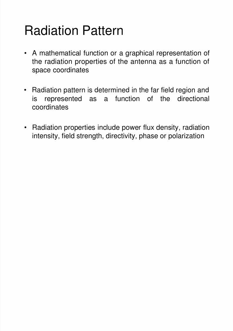
Radiation Pattern• A mathematical function or a graphical representation of
the radiation properties of the antenna as a function ofspace coordinates
is represented as a function of the directionalcoordinates
• Radiation properties include power flux density, radiationintensity, field strength, directivity, phase or polarization
7/31/2019 Lect Antenna Chap 02 i
http://slidepdf.com/reader/full/lect-antenna-chap-02-i 4/20
Radiation Pattern
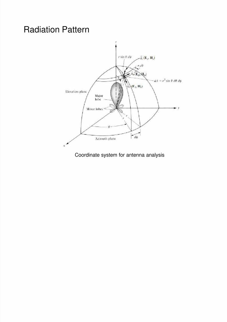
Coordinate system for antenna analysis
7/31/2019 Lect Antenna Chap 02 i
http://slidepdf.com/reader/full/lect-antenna-chap-02-i 5/20
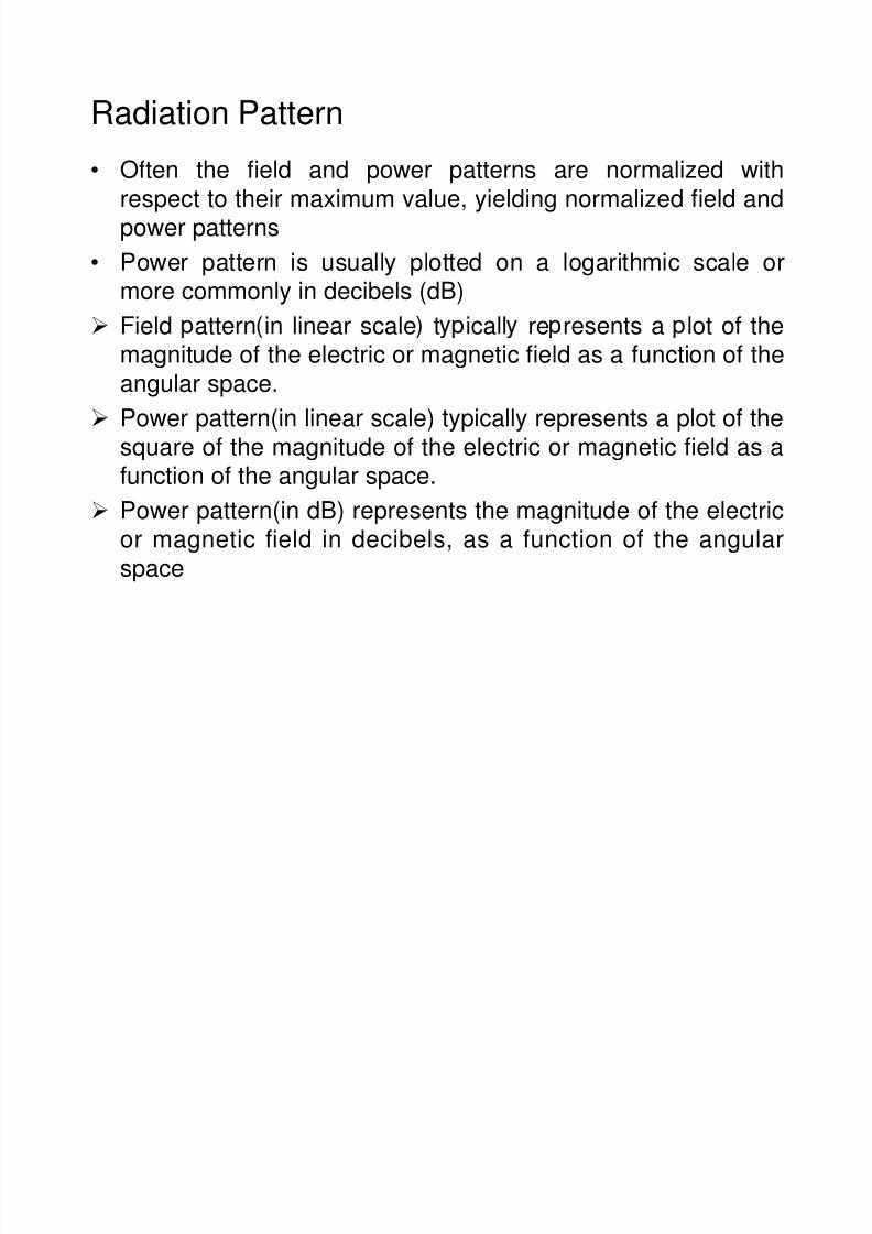
Radiation Pattern• Often the field and power patterns are normalized with
respect to their maximum value, yielding normalized field and
power patterns• Power pattern is usually plotted on a logarithmic scale or
more commonly in decibels (dB)
Field attern in linear scale t icall re resents a lot of the
magnitude of the electric or magnetic field as a function of theangular space.
Power pattern(in linear scale) typically represents a plot of the
square of the magnitude of the electric or magnetic field as a
function of the angular space.
Power pattern(in dB) represents the magnitude of the electricor magnetic field in decibels, as a function of the angular
space
7/31/2019 Lect Antenna Chap 02 i
http://slidepdf.com/reader/full/lect-antenna-chap-02-i 6/20
Radiation Pattern
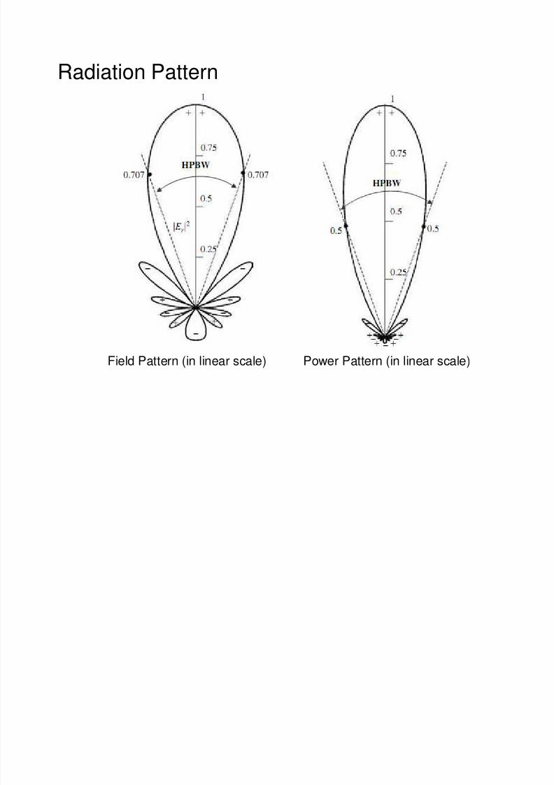
Field Pattern (in linear scale) Power Pattern (in linear scale)
7/31/2019 Lect Antenna Chap 02 i
http://slidepdf.com/reader/full/lect-antenna-chap-02-i 7/20
Radiation Pattern
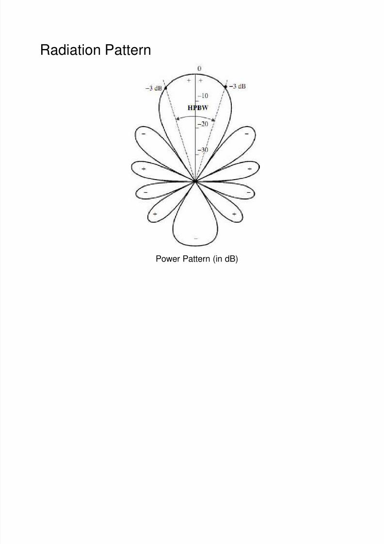
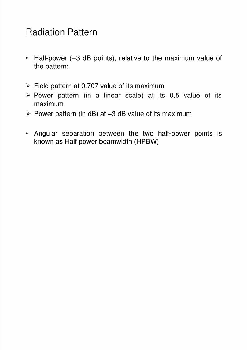
Power Pattern (in dB)
7/31/2019 Lect Antenna Chap 02 i
http://slidepdf.com/reader/full/lect-antenna-chap-02-i 8/20
Radiation Pattern
• Half-power (−3 dB points), relative to the maximum value of
the pattern:
Field pattern at 0.707 value of its maximum
.maximum
Power pattern (in dB) at −3 dB value of its maximum
• Angular separation between the two half-power points isknown as Half power beamwidth (HPBW)
7/31/2019 Lect Antenna Chap 02 i
http://slidepdf.com/reader/full/lect-antenna-chap-02-i 9/20
Radiation Pattern Lobes
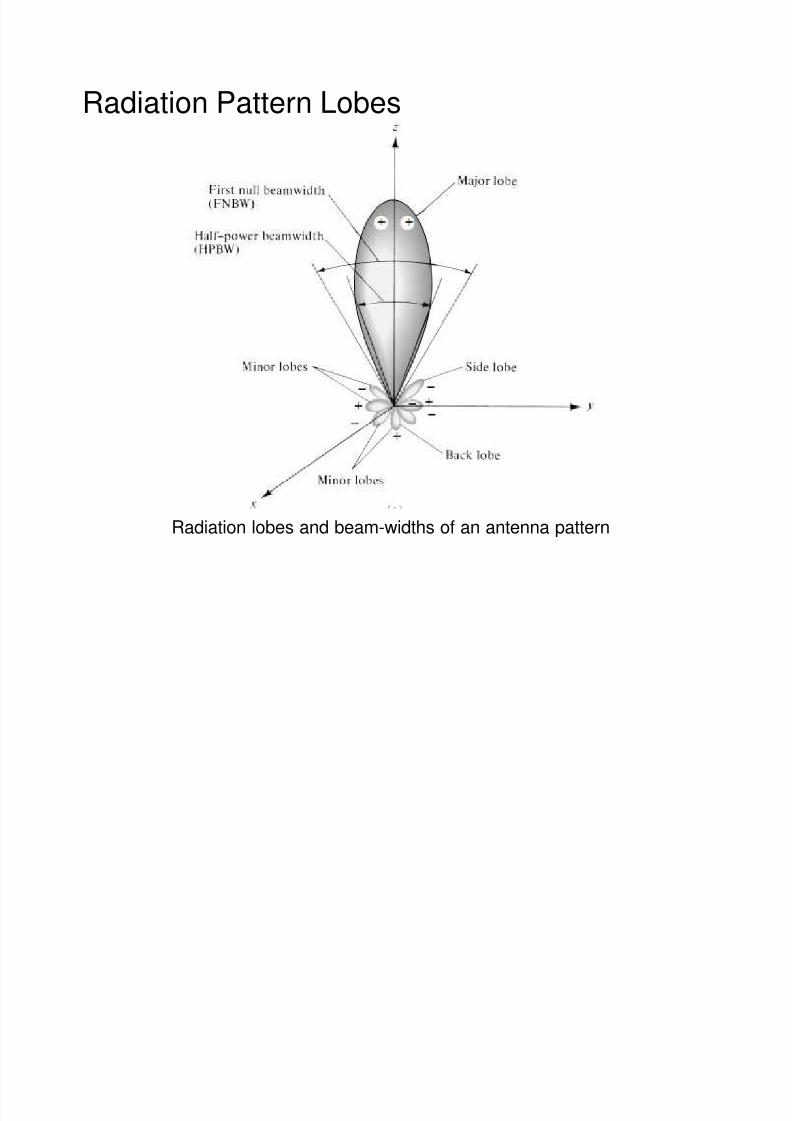
Radiation lobes and beam-widths of an antenna pattern
7/31/2019 Lect Antenna Chap 02 i
http://slidepdf.com/reader/full/lect-antenna-chap-02-i 10/20
Radiation Pattern Lobes
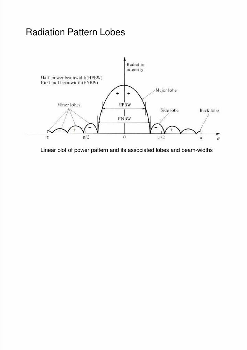
Linear plot of power pattern and its associated lobes and beam-widths
7/31/2019 Lect Antenna Chap 02 i
http://slidepdf.com/reader/full/lect-antenna-chap-02-i 11/20
Radiation Pattern Lobes
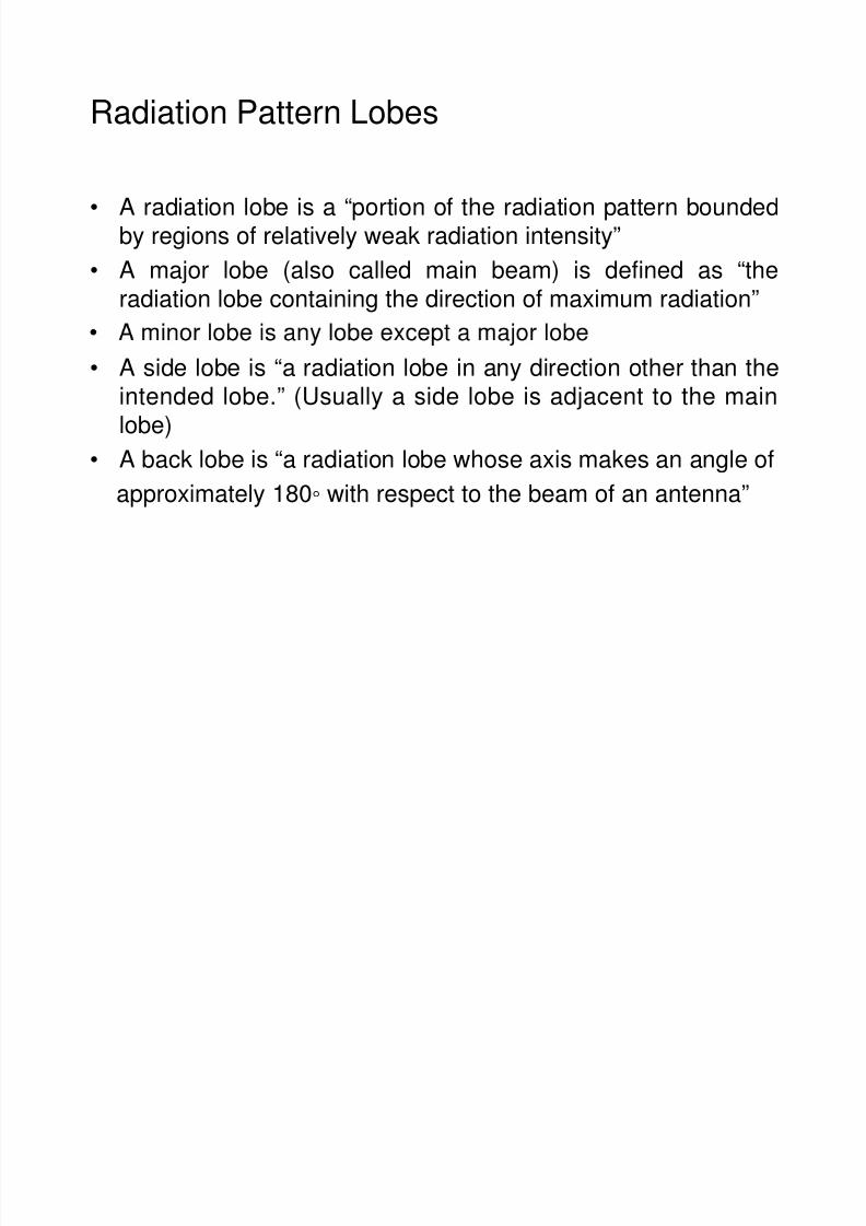
• A radiation lobe is a “portion of the radiation pattern bounded
by regions of relatively weak radiation intensity”• A major lobe (also called main beam) is defined as “the
radiation lobe containing the direction of maximum radiation”
• A side lobe is “a radiation lobe in any direction other than theintended lobe.” (Usually a side lobe is adjacent to the main
lobe)
• A back lobe is “a radiation lobe whose axis makes an angle ofapproximately 180 with respect to the beam of an antenna”
7/31/2019 Lect Antenna Chap 02 i
http://slidepdf.com/reader/full/lect-antenna-chap-02-i 12/20
Radiation Pattern Lobes
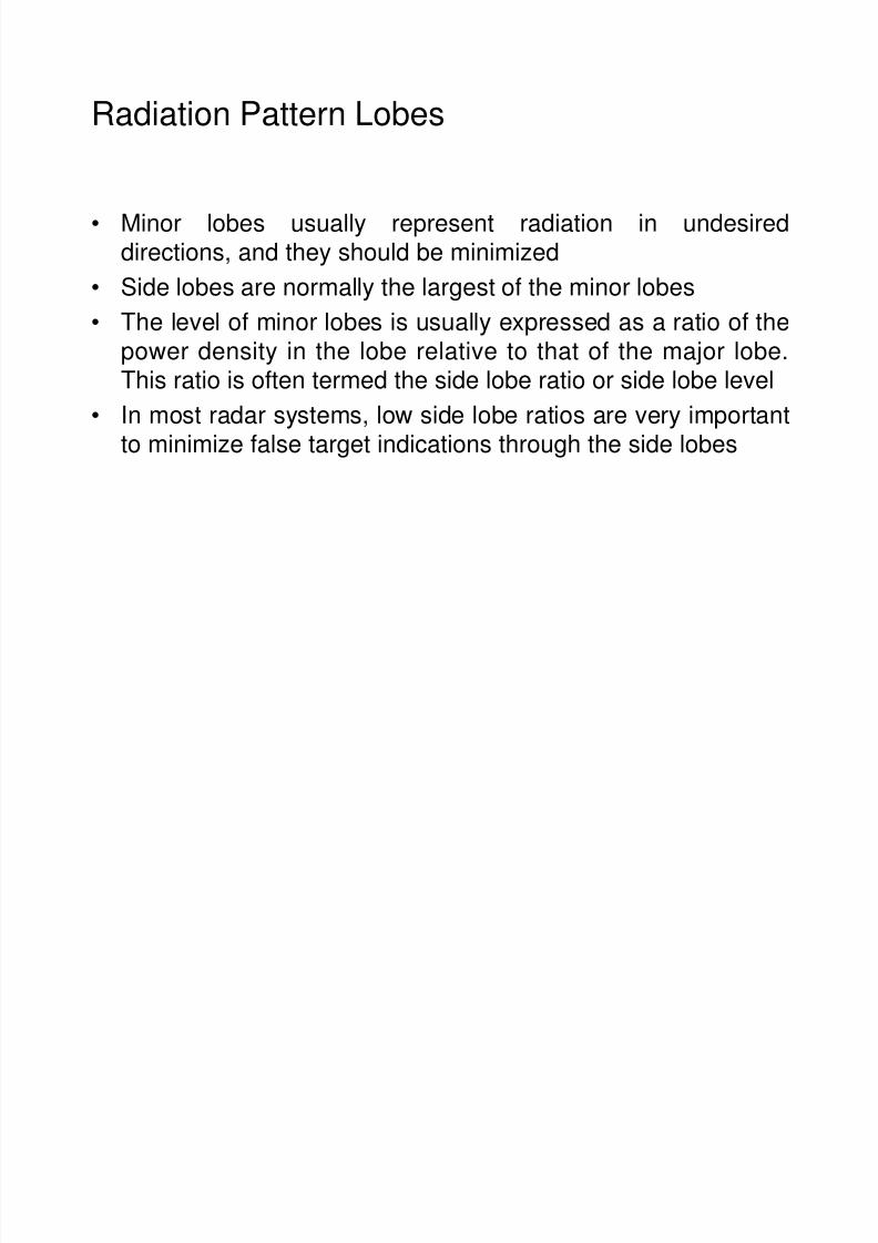
• Minor lobes usually represent radiation in undesireddirections, and they should be minimized
• Side lobes are normally the largest of the minor lobes
• The level of minor lobes is usually expressed as a ratio of the
power density in the lobe relative to that of the major lobe.This ratio is often termed the side lobe ratio or side lobe level
• In most radar systems, low side lobe ratios are very importantto minimize false target indications through the side lobes
7/31/2019 Lect Antenna Chap 02 i
http://slidepdf.com/reader/full/lect-antenna-chap-02-i 13/20
Radiation Pattern Lobes
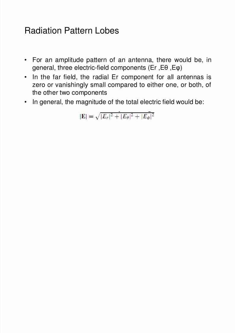
• For an amplitude pattern of an antenna, there would be, ingeneral, three electric-field components (Er ,Eθ ,Eφ)
• In the far field, the radial Er component for all antennas iszero or vanishingly small compared to either one, or both, of
t e ot er two components• In general, the magnitude of the total electric field would be:
7/31/2019 Lect Antenna Chap 02 i
http://slidepdf.com/reader/full/lect-antenna-chap-02-i 14/20
Isotropic, Directional and Omni-directional
Patterns
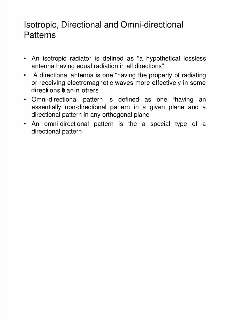
• An isotropic radiator is defined as “a hypothetical losslessantenna having equal radiation in all directions”
• A directional antenna is one “having the property of radiatingor receiving electromagnetic waves more effectively in some
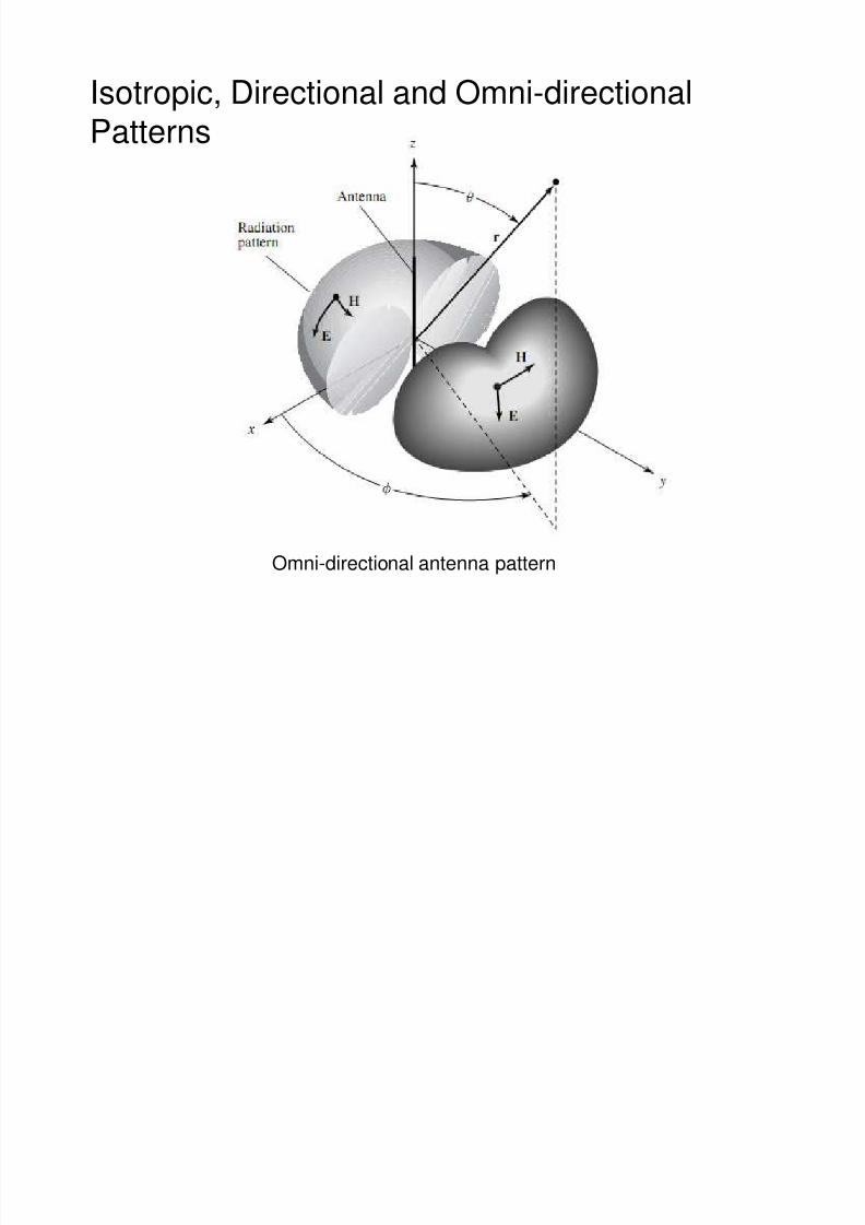
rect ons t an n ot ers• Omni-directional pattern is defined as one “having an
essentially non-directional pattern in a given plane and adirectional pattern in any orthogonal plane
• An omni-directional pattern is the a special type of adirectional pattern
7/31/2019 Lect Antenna Chap 02 i
http://slidepdf.com/reader/full/lect-antenna-chap-02-i 15/20
Isotropic, Directional and Omni-directional
Patterns
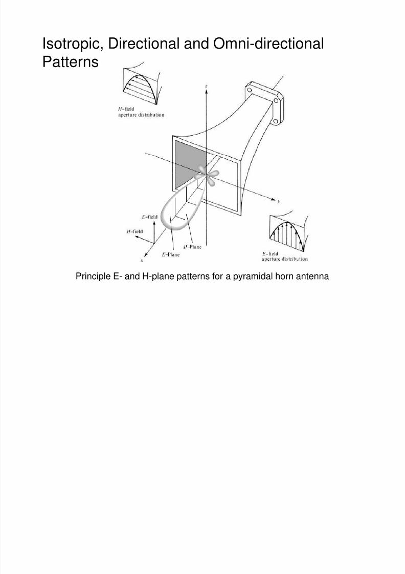
Principle E- and H-plane patterns for a pyramidal horn antenna
7/31/2019 Lect Antenna Chap 02 i
http://slidepdf.com/reader/full/lect-antenna-chap-02-i 16/20
Isotropic, Directional and Omni-directional
Patterns
Omni-directional antenna pattern
7/31/2019 Lect Antenna Chap 02 i
http://slidepdf.com/reader/full/lect-antenna-chap-02-i 17/20
Principle Patterns
• The E-plane is defined as “the plane containing the electric-
field vector and the direction of maximum radiation”
• The H-plane as “the plane containing the magnetic-fieldvector and the direction of maximum radiation”
7/31/2019 Lect Antenna Chap 02 i
http://slidepdf.com/reader/full/lect-antenna-chap-02-i 18/20
Radian and Steradian
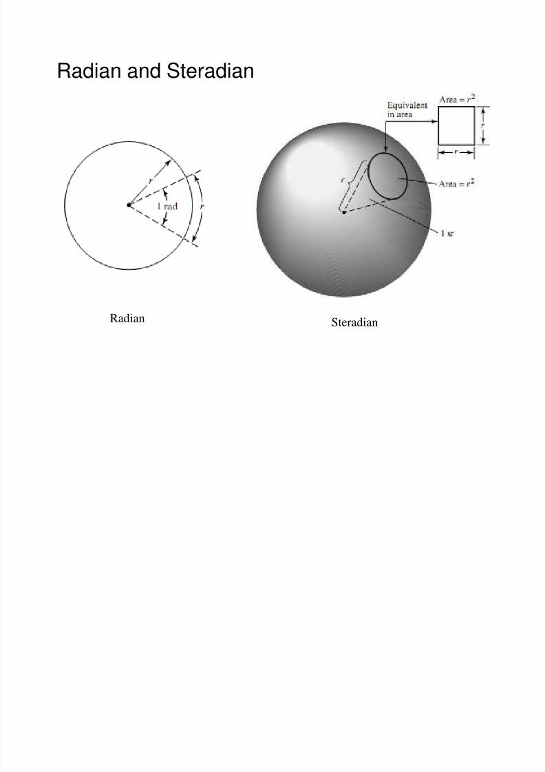
• The measure of a plane angle is a radian
• One radian is defined as the plane angle with its vertex at the
center of a circle of radius r that is subtended by an arc whoselength is r
• The circumference of a circle of radius r is C = 2πr,so, thereπ π
• The measure of a solid angle is a steradian
• One steradian is defined as the solid angle with its vertex at thecenter of a sphere of radius r that is subtended by a spherical
surface area equal to that of a square with each side of length r• The area of a sphere of radius r is A = 4πr2,so,there are 4π sr
(4πr2 /r2) in a closed sphere
7/31/2019 Lect Antenna Chap 02 i
http://slidepdf.com/reader/full/lect-antenna-chap-02-i 19/20
Radian and Steradian
Radian Steradian
7/31/2019 Lect Antenna Chap 02 i
http://slidepdf.com/reader/full/lect-antenna-chap-02-i 20/20
Radian and Steradian
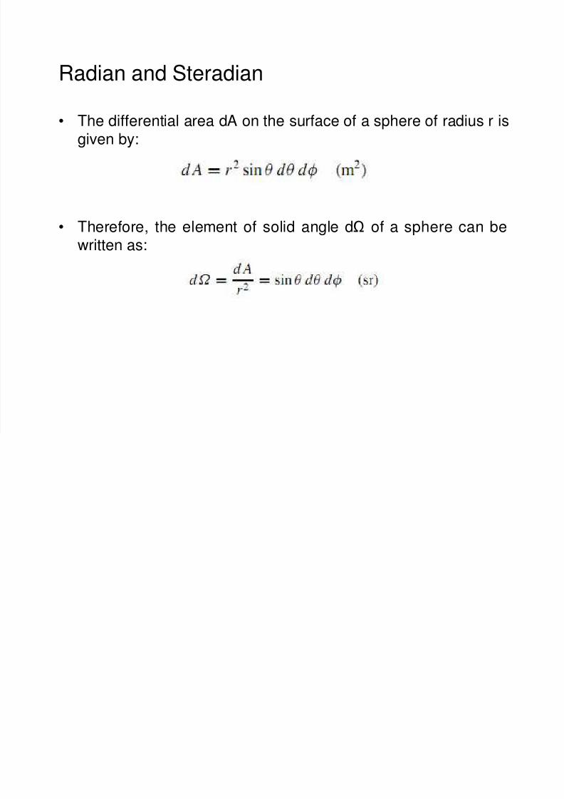
• The differential area dA on the surface of a sphere of radius r isgiven by:
• Therefore, the element of solid angle dΩ of a sphere can bewritten as: