Embed Size (px)
Citation preview

8/6/2019 Lect Mfsk Qam
http://slidepdf.com/reader/full/lect-mfsk-qam 1/10
Frequency-Shift Keying (FSK) Modulation and Quadrature Amplitude Modulation (QAM) on Mac
24. Frequency-Shift Keying (FSK) Modulation and Quadrature
Amplitude Modulation (QAM)
Binary Frequency-Shift Keying (BFSK) [1-3]
A binary frequency-shift keying (BFSK) signal can be defined by
s(t ) = A f t t T
A f t elsewhere
cos ,
cos ,
2 0 0
2 1
π
π
≤ ≤
(24.1)
where A is a constant, f 0 and f 1 are the transmitted frequencies, and T is the bit
duration. The signal has a power P = A2 /2, so that A = 2P . Thus equation (24.1)
can be written as
s(t ) =2 2 0 0
2 2 1
P f t t T
P f t elsewhere
cos ,
cos ,
π
π
≤ ≤
=
PT T
f t t T
PT T
f t elsewhere
22 0 0
22 1
cos ,
cos ,
π
π
≤ ≤
= E T f t t T
E T
f t elsewhere
2
2 0 0
22 1
cos ,
cos ,
π
π
≤ ≤
(24.2)
where E = PT is the energy contained in a bit duration. For orthogonality, f 0 = m / T
and f 1 = n / T for integer n > integer m and f 1 - f 0 must be an integer multiple of
1/2T. We can take φ 1(t ) =2
T cos 2π f 0 t and φ 2 ( t ) =
2
T sin 2π f 1 t as the
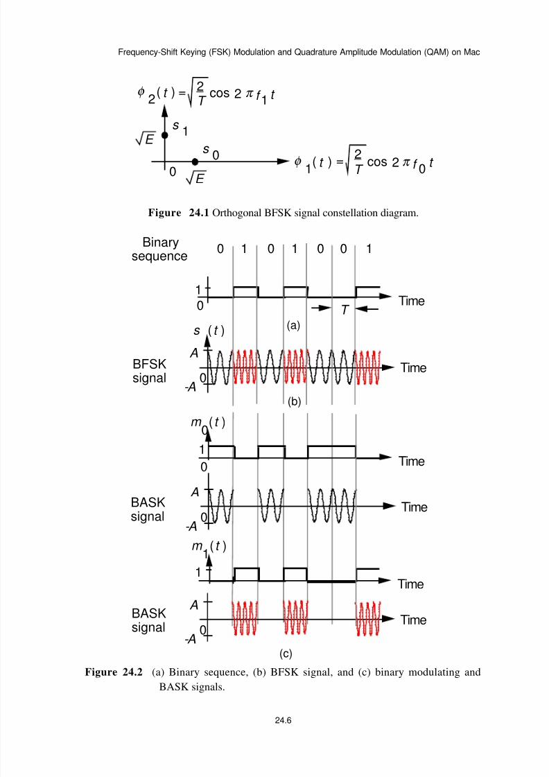
orthonormal basis functions [3]. The applicable signal constellation diagram of the
orthogonal BFSK signal is shown in Figure 24.1.
Figure 24.1 Orthogonal BFSK signal constellation diagram.
Figure 24.2 shows the BFSK signal sequence generated by the binary sequence
0 1 0 1 0 0 1.
Figure 24.2 (a) Binary sequence, (b) BFSK signal, and (c) binary modulating and
BASK signals.
24.1
8/6/2019 Lect Mfsk Qam
http://slidepdf.com/reader/full/lect-mfsk-qam 2/10
Frequency-Shift Keying (FSK) Modulation and Quadrature Amplitude Modulation (QAM) on Mac
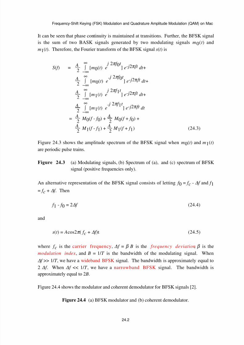
It can be seen that phase continuity is maintained at transitions. Further, the BFSK signal
is the sum of two BASK signals generated by two modulating signals m0(t ) and
m1(t ). Therefore, the Fourier transform of the BFSK signal s(t ) is
S( f ) = A2 −∞
∞∫ [m0(t ) e
j 2π f 0t ] e- j2π ft dt +
A2 −∞
∞∫ [m0(t ) e
- j 2π f 0t ] e- j2π ft dt +
A2 −∞
∞∫ [m1(t ) e
j 2π f 1t ] e- j2π ft dt +
A2 −∞
∞∫ [m1(t ) e
- j 2π f 1t ] e- j2π ft dt
=
A
2 M 0( f - f 0) +
A
2 M 0( f + f 0) + A2
M 1( f - f 1) + A
2 M 1( f + f 1) (24.3)
Figure 24.3 shows the amplitude spectrum of the BFSK signal when m0(t ) and m1(t )
are periodic pulse trains.
Figure 24.3 (a) Modulating signals, (b) Spectrum of (a), and (c) spectrum of BFSK
signal (positive frequencies only).
An alternative representation of the BFSK signal consists of letting f 0 = f c - ∆ f and f 1
= f c + ∆ f . Then
f 1 - f 0 = 2∆ f (24.4)
and
s(t ) = Acos2π ( f c + ∆ f )t (24.5)
where f c is the carrier frequency, ∆ f = β B is the frequency deviation, β is the
modulation index, and B = 1/ T is the bandwidth of the modulating signal. When
∆ f >> 1/ T , we have a wideband BFSK signal. The bandwidth is approximately equal to
2 ∆ f . When ∆ f << 1/ T , we have a narrowband BFSK signal. The bandwidth is
approximately equal to 2 B.
Figure 24.4 shows the modulator and coherent demodulator for BFSK signals [2].
Figure 24.4 (a) BFSK modulator and (b) coherent demodulator.
24.2
8/6/2019 Lect Mfsk Qam
http://slidepdf.com/reader/full/lect-mfsk-qam 3/10
Frequency-Shift Keying (FSK) Modulation and Quadrature Amplitude Modulation (QAM) on Mac
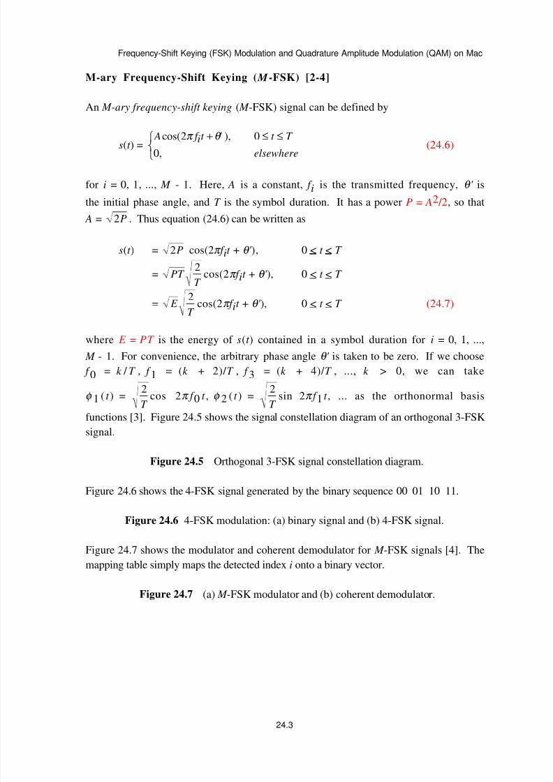
M-ary Frequency-Shift Keying ( M -FSK) [2-4]
An M-ary frequency-shift keying ( M -FSK) signal can be defined by
s(t ) = A f it t T elsewhere
cos( ' ),
,
2 0
0
π θ + ≤ ≤
(24.6)
for i = 0, 1, ..., M - 1. Here, A is a constant, f i is the transmitted frequency, θ ' is
the initial phase angle, and T is the symbol duration. It has a power P = A2 /2, so that
A = 2P . Thus equation (24.6) can be written as
s(t ) = 2P cos(2π f it + θ ' ), 0 < t < T
= PT T
2cos(2π f it + θ ' ), 0 < t < T
= E T
2cos(2π f it + θ ' ), 0 < t < T (24.7)
where E = PT is the energy of s(t ) contained in a symbol duration for i = 0, 1, ...,
M - 1. For convenience, the arbitrary phase angle θ ' is taken to be zero. If we choose
f 0 = k / T , f 1 = (k + 2)/ T , f 3 = (k + 4)/ T , ..., k > 0, we can take
φ 1 ( t ) =2
T cos 2π f 0 t , φ 2 ( t ) =
2
T sin 2π f 1 t , ... as the orthonormal basis
functions [3]. Figure 24.5 shows the signal constellation diagram of an orthogonal 3-FSK
signal.
Figure 24.5 Orthogonal 3-FSK signal constellation diagram.
Figure 24.6 shows the 4-FSK signal generated by the binary sequence 00 01 10 11.
Figure 24.6 4-FSK modulation: (a) binary signal and (b) 4-FSK signal.
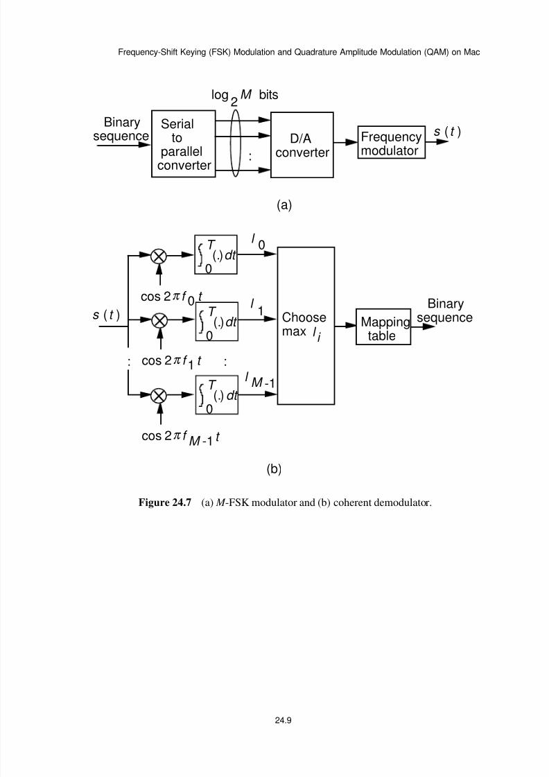
Figure 24.7 shows the modulator and coherent demodulator for M -FSK signals [4]. Themapping table simply maps the detected index i onto a binary vector.
Figure 24.7 (a) M -FSK modulator and (b) coherent demodulator.
24.3

8/6/2019 Lect Mfsk Qam
http://slidepdf.com/reader/full/lect-mfsk-qam 4/10
Frequency-Shift Keying (FSK) Modulation and Quadrature Amplitude Modulation (QAM) on Mac
M-ary Quadrature Amplitude Modulation ( M -QAM)
An M-ary quadrature amplitude modulation ( M -QAM) signal can be defined by
s(t ) = Ai f ct i t T
elsewhere
cos( ),
,
2 0
0
π θ + ≤ ≤
(24.8)
= Ai i f ct Ai i f ct t T
elsewhere
cos cos sin sin ,
,
θ π θ π 2 2 0
0
− ≤ ≤
(24.9)
for i = 0, 1, ..., M - 1. Here, Ai is the amplitude, f c is the carrier frequency, θ i is
the phase angle, and T is the symbol duration. It has a power Pi = Ai2 /2, so that
Ai = 2Pi . Thus equation (24.9) can be written as
s(t ) = PiT cosθ i2
T cos2π f ct - PiT sinθ i
2
T sin2π f ct
= E i cosθ i2
T cos2π f ct - E i sinθ i
2
T sin2π f ct (24.10)
where E i = PiT is the energy of s(t ) contained in a symbol duration for i = 0, 1, ...,
M - 1. If we take φ 1
( t ) =2
T cos 2π f
ct and φ
2(t ) = -
2
T sin 2π f
ct as the
orthonormal basis functions, the applicable signal constellation diagrams of the 16-QAM
and 4-QAM signals are shown in Figure 24.8.
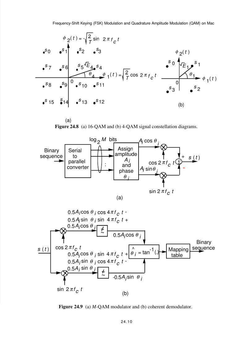
Figure 24.8 (a) 16-QAM and (b) 4-QAM signal constellation diagrams.
Figure 24.9 shows the modulator and a possible implementation of the coherent
demodulator for M -QAM signals.
Figure 24.9 (a) M -QAM modulator and (b) coherent demodulator.
References
[1] M. Schwartz, Information Transmission, Modulation, and Noise, 4/e, McGraw
Hill, 1990.
[2] P. Z. Peebles, Jr., Digital Communication Systems, Prentice Hall, 1987.
[3] H. Taub and D. L. Schilling, Principles of Communication Systems, 2/e, McGraw
Hill, 1986
24.4
8/6/2019 Lect Mfsk Qam
http://slidepdf.com/reader/full/lect-mfsk-qam 5/10
Frequency-Shift Keying (FSK) Modulation and Quadrature Amplitude Modulation (QAM) on Mac
[4] F. Xiong, Digital Modulation Techniques, Artech House, 2000.
24.5
8/6/2019 Lect Mfsk Qam
http://slidepdf.com/reader/full/lect-mfsk-qam 6/10
Frequency-Shift Keying (FSK) Modulation and Quadrature Amplitude Modulation (QAM) on Mac
0
E
s
1
E
s 0 =
2T
cos 2 π f 0t
= 2T
cos 2 π f 1 t
φ 1
t ( )
φ 2
t ( )
Figure 24.1 Orthogonal BFSK signal constellation diagram.
0 1 0 1 0 0 1Binary
sequence
0
A
-A
TimeBFSKsignal
s ( t )
T 0
(a)
Time1
(b)
(c)
0
A
-A
TimeBASKsignal
0
A
-A
TimeBASKsignal
m ( t )0
Time1
0
Time1
m ( t )1
Figure 24.2 (a) Binary sequence, (b) BFSK signal, and (c) binary modulating and
BASK signals.
24.6

8/6/2019 Lect Mfsk Qam
http://slidepdf.com/reader/full/lect-mfsk-qam 7/10
Frequency-Shift Keying (FSK) Modulation and Quadrature Amplitude Modulation (QAM) on Mac
(c)
(b)
f 0
B 1T
3T
-1T
Envelope1
T 2
2T
=-2T
-3T
(a)
0
...2B
01T 0 -3
T 0 -
1
T 2
f
1T
0 +f f f 3T
0 +f
S ( f )
f 1T
1 + f 3T
1 +
f f
2B
1f 1
T 1 -f 3
T 1 -
Envelope1
T 2
f c
2∆ f
0 1 0 1
0t
m ( t )
1
0M ( f )
0M ( f )
1or
t
T 0 2T 3T
1
m ( t )1
∆β =
B
f
Figure 24.3 (a) Modulating signals, (b) Spectrum of (a), and (c) spectrum of BFSK
signal (positive frequencies only).
(a) (b)
m ( t )
f t cosA 2π 0
s ( t )
f t cosA 2π 1
m ( t )
0
1
f t cos 2π 0s ( t )
~~
f t cos 2π 1
~~
1Am 0.5 f t cos 4π ( t )+ Am ( t )0.5
1
1
+ Am ( t )0.50Am 0.5 f t cos 4π ( t )0
0Am ( t )0.5
0
Am ( t )0.51
+
- 0
m ( t )0or
m ( t )1
ΣΣ
Figure 24.4 (a) BFSK modulator and (b) coherent demodulator.
24.7

8/6/2019 Lect Mfsk Qam
http://slidepdf.com/reader/full/lect-mfsk-qam 8/10
Frequency-Shift Keying (FSK) Modulation and Quadrature Amplitude Modulation (QAM) on Mac
0E
E
s
1
s 0 =
2T
cos 2 π f 0 t
= 2T
cos 2 π f 1 t
=2T
cos 2 π f 2t
E
s 2
φ 1 t ( )
φ 2
t ( )
φ 3
t ( )
Figure 24.5 Orthogonal 3-FSK signal constellation diagram.
0
A
-A
Time
0 0 0 1 1 0 1 1
Time
T
(b)
T
0
4-FSKsignal
(a)
Binarysequence
1
s ( t )
Figure 24.6 4-FSK modulation: (a) binary signal and (b) 4-FSK signal.
24.8
8/6/2019 Lect Mfsk Qam
http://slidepdf.com/reader/full/lect-mfsk-qam 9/10
Frequency-Shift Keying (FSK) Modulation and Quadrature Amplitude Modulation (QAM) on Mac
(a)
s (
t )
f t cos 2π 0s ( t )
f t cos 2π 1:
f t cos 2π -1M
:
l 0
Choosemax l
i
l 1
l -1M
(b)
0
T dt (.)
Serial
toparallelconverter
Frequencymodulator
D/Aconverter:
log2
M bits
Binary
sequence
Mappingtable
Binarysequence
0
T dt (.)
0
T dt (.)
Figure 24.7 (a) M -FSK modulator and (b) coherent demodulator.
24.9
8/6/2019 Lect Mfsk Qam
http://slidepdf.com/reader/full/lect-mfsk-qam 10/10
Frequency-Shift Keying (FSK) Modulation and Quadrature Amplitude Modulation (QAM) on Mac
s 1s 3
s 7 s 6
s 5 s 4
s 8 s 9 s
s s s s
0s
s 2s 0
1110
15 14 13 12
θ 4
E 4s 0 s 1
s 3
0s
2
E 1
θ 1
(a)
(b)
=2T
cos 2 π f c t φ
1t ( )
= - 2T
sin 2 π f c
t φ 2
t ( )
φ 2 t ( )
φ 1
t ( )
Figure 24.8 (a) 16-QAM and (b) 4-QAM signal constellation diagrams.
Binarysequence
(a)
Serialto
parallelconverter
:
log2
M bits
f t cos
A
2π c
f t sin 2π c
s ( t )+
cos θ i
-
i
A sinθ i i
f t cos 2π c s ( t )
f t sin 2π c
~~
~~
cos θ i
A0.5
sin θ i
A-0.5
cos θ i
f t cos 4π c -cos θ i
f t sin 4π c +sin θ i
A0.5
A0.5
A0.5
sin θ i
f t sin 4π c
+cos θ i
f t cos 4π c
-sin θ i
A0.5
A0.5
A0.5
= tan-1
θ i (.)^ Mapping
table
i
i
i
i
i
i
i
i
(b)
Assignamplitude
andphaseθ
i
A i
Binarysequence
Σ
Figure 24.9 (a) M -QAM modulator and (b) coherent demodulator.
24.10


![[Laptrinh.vn]-Bộ điều chế qam](https://img.pdfslide.tips/doc/110x75/5571fc884979599169976f96/laptrinhvn-bo-dieu-che-qam.jpg)