Embed Size (px)
Citation preview

AML 883 Properties and selection of engineering materials
LECTURE 12. Toughness: fracture and fatigue
M P GururajanEmail: [email protected]
Room No. MS 207/A3 Phone: 1340

Cracks in materials
● Machining – surface cracks● Shrinkage in casting and welding – introduces
cracks● Cracking of inclusions during rolling –
introduces cracks● During service – abrasion, contact stresses,
cyclic loading, ...
Rail cracking
Cracks on a rail – Image courtesy: University of Birmingham site
Rail cracking
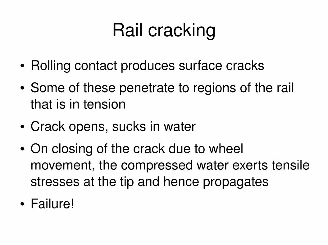
● Rolling contact produces surface cracks● Some of these penetrate to regions of the rail
that is in tension● Crack opens, sucks in water● On closing of the crack due to wheel
movement, the compressed water exerts tensile stresses at the tip and hence propagates
● Failure!

The path from crack to fracture
● Most of engineering applications – we do not want cracks
● Even if there be some cracks – we do not want them to propagate
● Or, even if they propagate, we want it to be controlled
● As usual, there might be cases where you do want cracks! (Aircraft engines attached to the wing by shear bolts – desinged to fail and shed the engine if it suddenly seizes)

Toughness
● Resistance of a material to the propagation of crack
● When the crack does propagate, we get fracture
● Fracture: ductile (metal or alloy) and brittle (glass, polymer much below its Tg and ceramics)
● Fatigue fracture: failure under repeated loading (even though the loads themselves might well be within the limits)

Fracture
Ductile and brittle
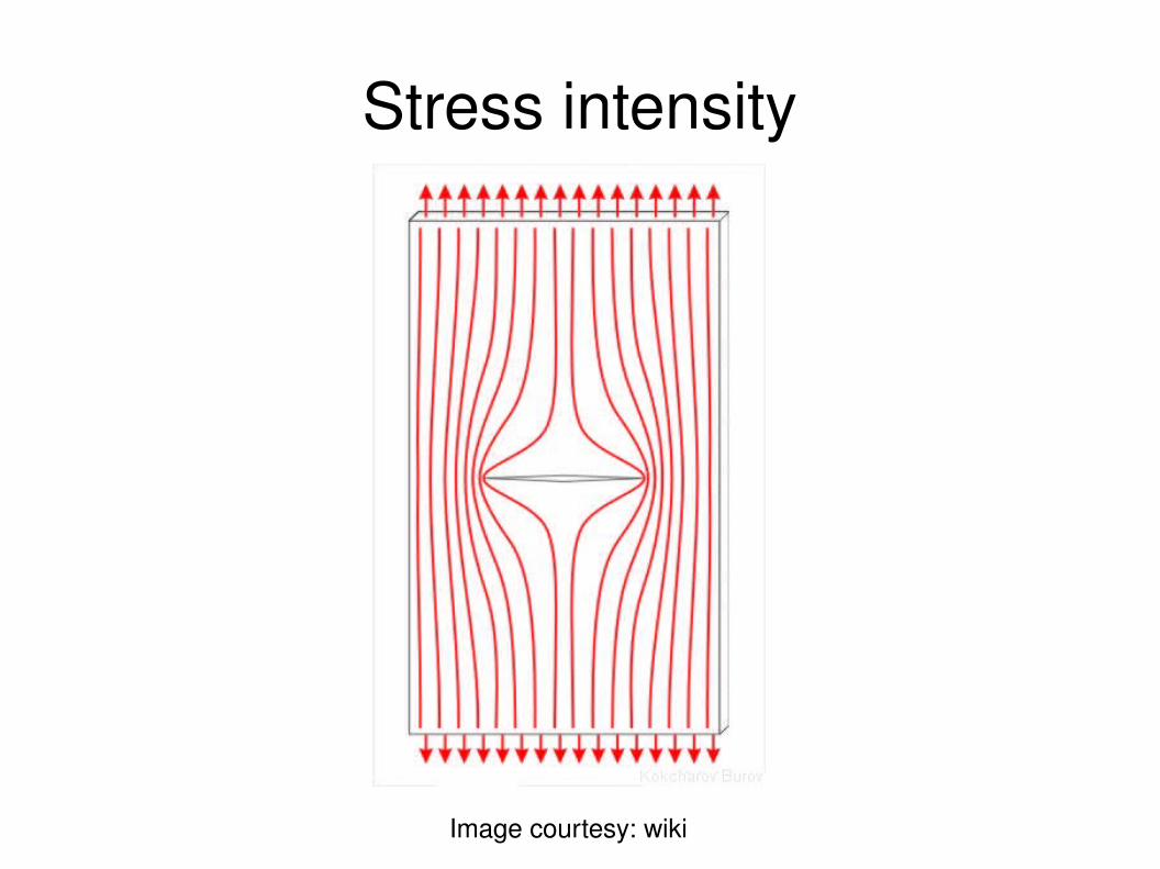
Stress intensity
Image courtesy: wiki
Stress intensity
● Cracks concentrate stress● What happened to our formula (for notches and
holes)?● Does not hold here since the crack tip radius is
essentially zero● However, a similar formula for the concentration
of stress at the tip can be obtained
=0

Why cracks are bad newsImage courtesy: wiki (withmodifications of my own)
loc
c
loc
=[1Y c /2 r 1 /2 ]
r(r)
r
loc

Stress intensity factor
●
● Y – a constant of value near unity with weak dependence on geometry
● For r << c,● Mode 1 stress intensity factor:
● What is Mode 1: a one slide digression
loc
=[1Y c /2 r 1 /2 ]
loc
=Y c /2 r 1 /2
K1=Y c1/2
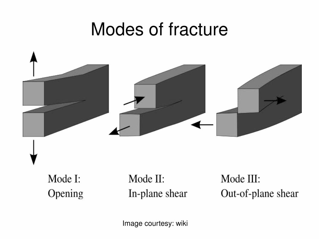
Modes of fracture
Image courtesy: wiki
Fracture toughness
● Cracks propagate when stress intensity factor exceeds a critical value
● This critical value is called fracture toughness,
● Fracture toughness is a material property: it is independent of the way it is measured; it can be used in design
K1c
Energy release rate
● Fracture of sample: new surface is created● Surfaces cost system energy● Surface energy:● Fracture of a sample of crosssectional area A
costs● If external work done or elastic energy released
is equal to or greater than the surface energy, then fracture will happen:
● G: energy release rate (necessary condition)
2 A
G≥2
Energy release rate
● In practice, due to the plastic deformation at the crack tip, much more than is needed.
● Gc: critical strain energy release rate – a sort of effective surface energy (also called toughness, at times)
● How is Gc related to fracture toughness?
2
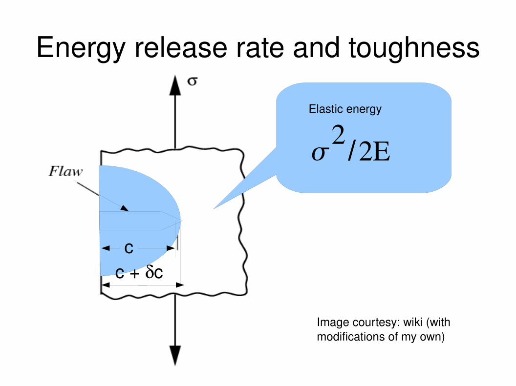
Energy release rate and toughness
cc + c
2/2E
Elastic energy
Image courtesy: wiki (with modifications of my own)
Energy release rate
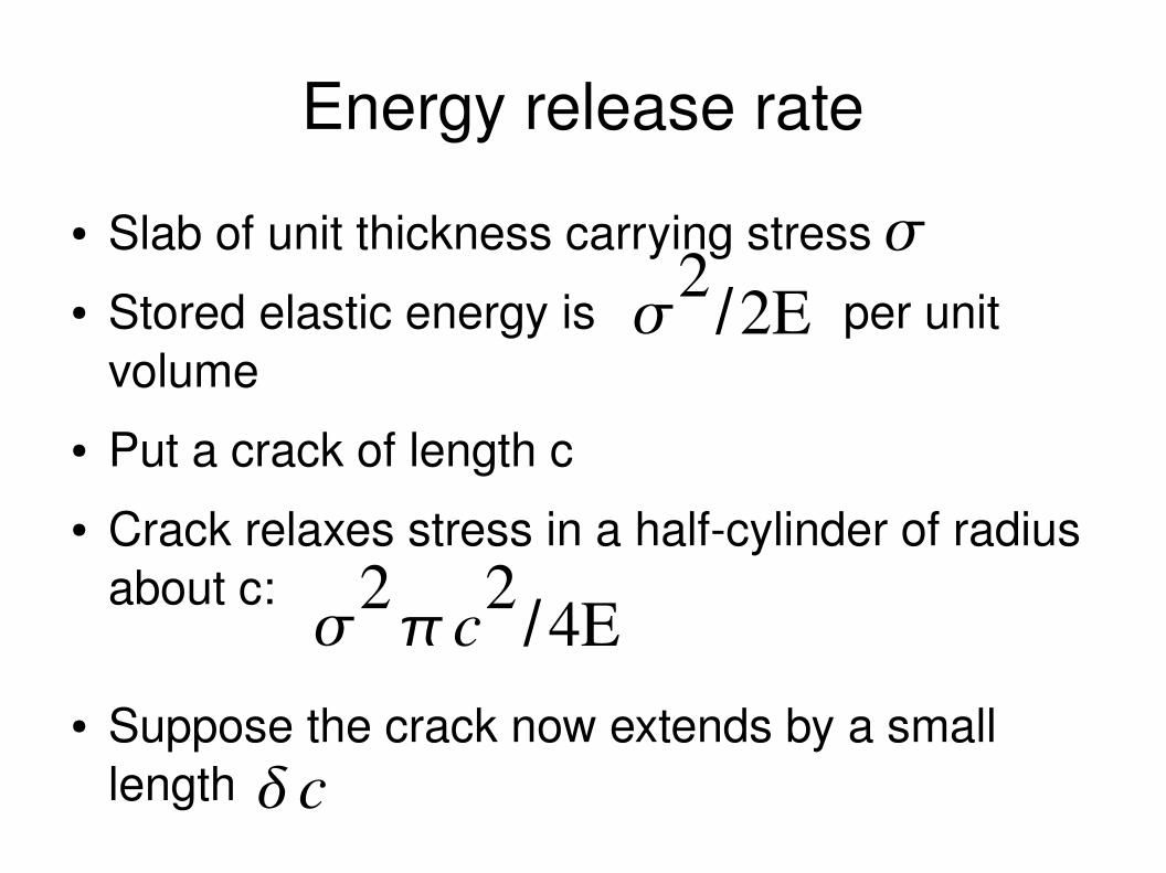
● Slab of unit thickness carrying stress● Stored elastic energy is per unit
volume● Put a crack of length c● Crack relaxes stress in a halfcylinder of radius
about c:
● Suppose the crack now extends by a small length
2/2E
2c2
/4E
c
Energy release rate
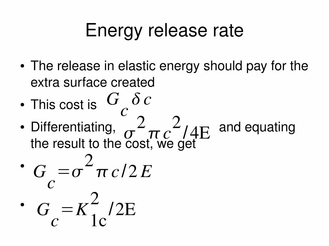
● The release in elastic energy should pay for the extra surface created
● This cost is ● Differentiating, and equating
the result to the cost, we get●
●
Gc c
Gc=
2c /2 E
2c2
/4E
Gc=K
1c2
/2E
Energy release rate
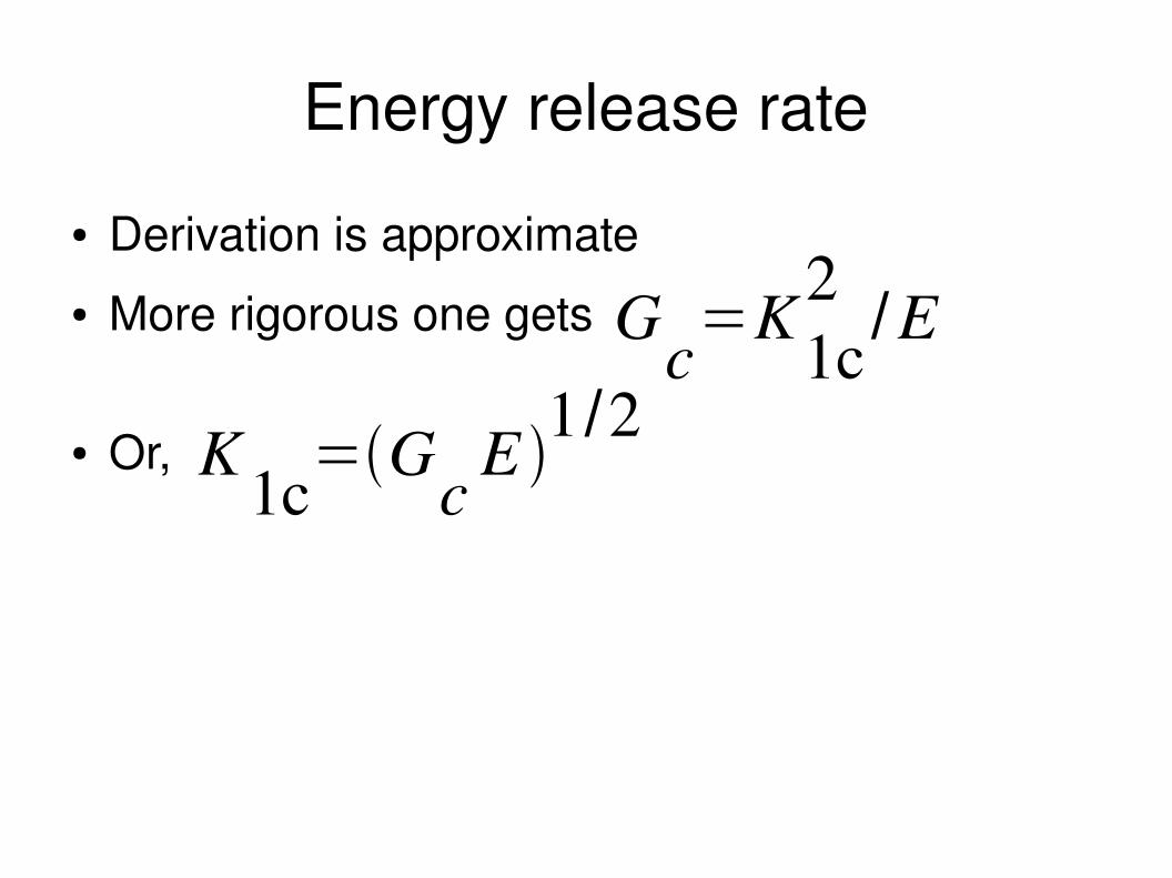
● Derivation is approximate● More rigorous one gets
● Or,
Gc=K
1c2
/E
K1c=G
cE
1/2

Process zone at the crack tip
● Stress at crack tip: affects the zone ahead – called process zone
● Ductile solids – plastic zone● Ceramics – region of microcracking● Composites – region of delamination,
debonding and fibre pullout● Work done against plastic and/or frictional
forces – accounts for the effective surface energy being higher than just surface energy
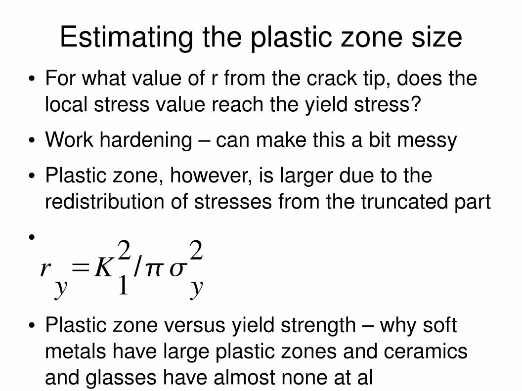
Estimating the plastic zone size● For what value of r from the crack tip, does the
local stress value reach the yield stress?● Work hardening – can make this a bit messy● Plastic zone, however, is larger due to the
redistribution of stresses from the truncated part●
● Plastic zone versus yield strength – why soft metals have large plastic zones and ceramics and glasses have almost none at al
ry=K
12/
y2

Plastic zone at crack tipImage courtesy: wiki (withmodifications of my own)
loc
c r(r)
r
loc
Plastic zone
y
ry
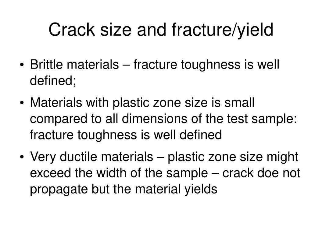
Crack size and fracture/yield
● Brittle materials – fracture toughness is well defined;
● Materials with plastic zone size is small compared to all dimensions of the test sample: fracture toughness is well defined
● Very ductile materials – plastic zone size might exceed the width of the sample – crack doe not propagate but the material yields
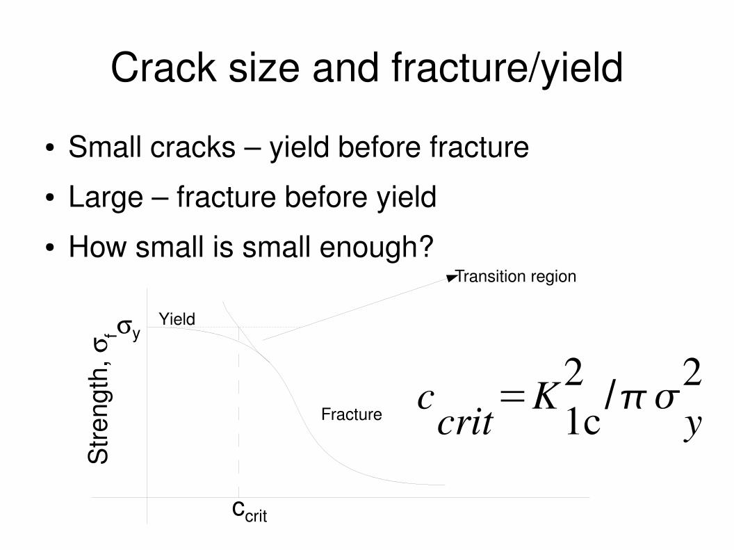
Crack size and fracture/yield
● Small cracks – yield before fracture● Large – fracture before yield● How small is small enough?
y
Stre
ngth
, f
Transition region
Yield
Fracture
ccrit
ccrit
=K1c2
/y2
Transition crack lengths
● Metals: 11000 mm● Polymers: 0.110 mm● Ceramics: 0.01 0.1 mm● Composites: 0.1 10 mm● Cracks lengths – measure of damage tolerance
Fracture
Fatigue
Cyclic loading
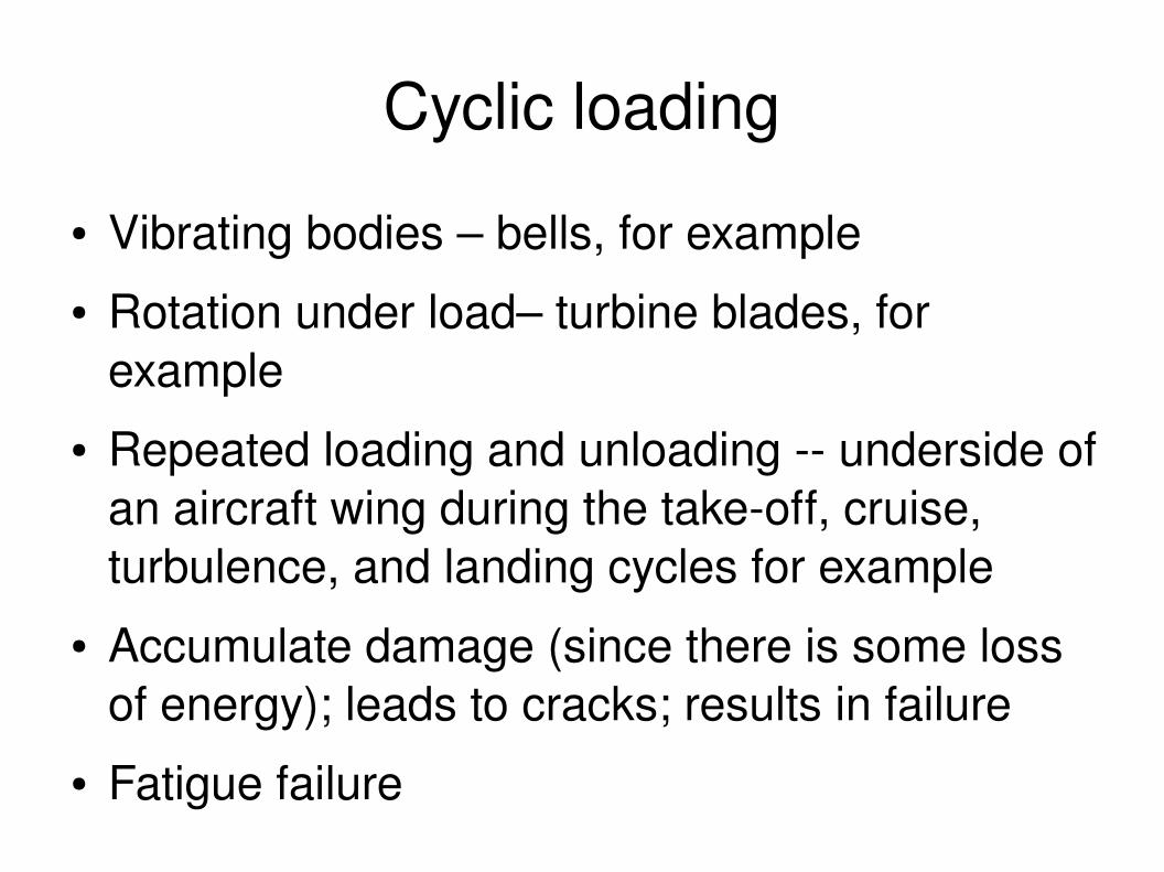
● Vibrating bodies – bells, for example● Rotation under load– turbine blades, for
example● Repeated loading and unloading underside of
an aircraft wing during the takeoff, cruise, turbulence, and landing cycles for example
● Accumulate damage (since there is some loss of energy); leads to cracks; results in failure
● Fatigue failure

Mechanical loss coefficient
● Damping coefficient● A measure of the degree to which a material
dissipates vibrational energy● Fraction of stored elastic energy during loading
that is not returned during unloading● Materials for bells – low damping coefficient
(bronze and glass)● Damping – Materials with high damping
coefficient: foams, elastomers, polymers, ...
Low cycle fatigue
● Low cycle fatigue: cycling above general yield (but below tensile strength)
● Why would you want to cycle above yield?Where do we use these?
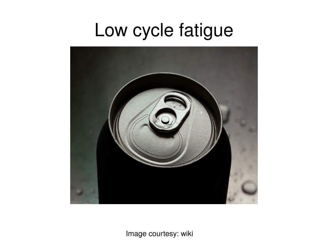
Low cycle fatigue
Image courtesy: wiki
High cycle fatigue
● High cycle fatigue: cycling well below general yield
● Generally elastic stresses, well below the yield stress
● Cracks nonetheless develop and cause failure● Fan blade example

Fatigue tests on fanblades

Fatigue
● Initiation controlled – initial material is crackfree● Propagation controlled – initial material does
contain cracks – but the rate of growth of crack is what matters for failure
● How to measure the fatigue strength of materials?


![THE EFFECT OF SECONDARY METALWORKING PROCESSES ON … · The general dependence of fracture toughness on yield strength. Based on [4] ... means that for the same crack growth resistance](https://img.pdfslide.tips/doc/110x75/5f672b842d17bd2398498312/the-effect-of-secondary-metalworking-processes-on-the-general-dependence-of-fracture.jpg)