Embed Size (px)
Citation preview
Lecture 5 Design
CS 540 – Quantitative Software Engineering
Architecture is synthesis
Design is analysis
Management is work!
“The techniques of communication and organization demand from the manager as much thought and as much experience and competence as the softwareitself.” - Brooks, p83
Key Word in Context index –a concordance
Generate n shifts where n is the number of words in a line.
Eliminate non keywords. Sort Lines in alphabetic order by keyword.
adapted from Parnas
Main Program with subroutines
Decompose tasks• Read & store input
• Eliminate ‘noise’ words
• Shift to keyword
• Sort the shifted lines
• Write the sorted lines
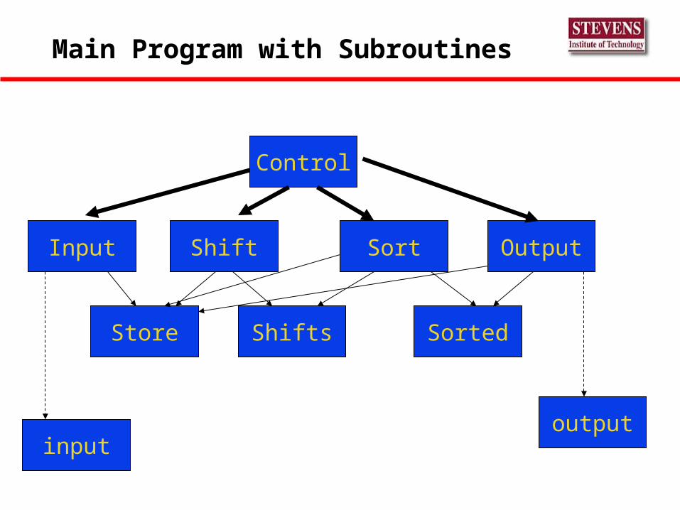
Main Program with Subroutines
Input Shift
Store Shifts Sorted
input
Sort Output
output
Control
Abstract Data types
Make data representation type decisions early Access data through procedures rather than
directly• Design stage only requires agreement about
procedure interface
• Changes in data can be made easily w/o affecting other modules
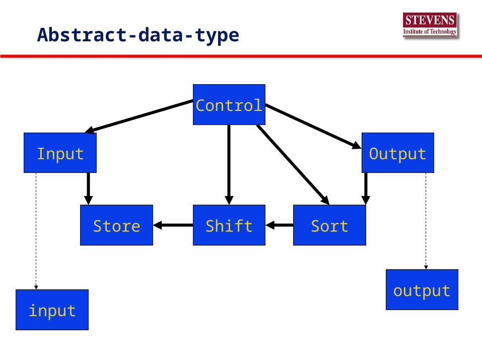
Abstract-data-type
Input Output
Control
SortShiftStore
outputinput
Implicit Invocation
Want to get rid of uninteresting shifts (or include only interesting shifts)
Could filter the data but it is inefficient Change the shift module - but we may be messing with it
too much Solution - we do not explicitly call make shift we generate
an EVENT.
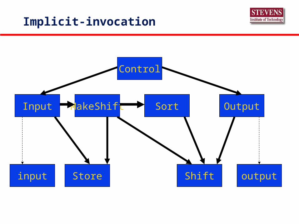
Implicit-invocation
Input MakeShift Sort Output
Store Shiftinput output
Control
Pipes and filters
Good old UNIX Since each program reads it input in same order
we can use pipes and filters But Error handling is primitive as UNIX uses
separate error channel.
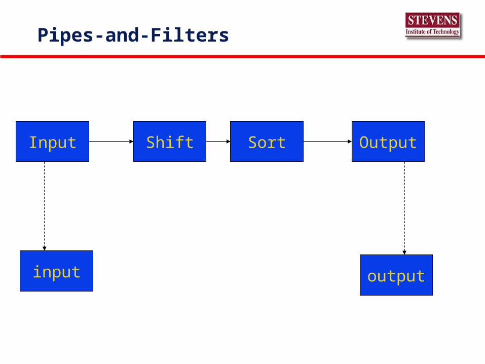
Pipes-and-Filters
Input Shift Sort Output
input output
Evaluation of these architectures
All work Differences become apparent if we evaluate them
on some criteria.
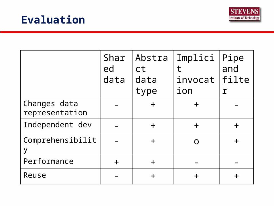
Evaluation
Shared data
Abstract data type
Implicit invocation
Pipe and filter
Changes data representation
- + + -
Independent dev - + + +
Comprehensibility - + o +
Performance + + - -Reuse - + + +
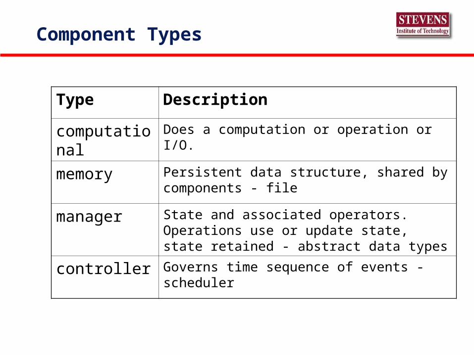
Component Types
Type Description
computational Does a computation or operation or I/O.
memory Persistent data structure, shared by components - file
manager State and associated operators. Operations use or update state, state retained - abstract data types
controller Governs time sequence of events - scheduler
Reality
In practice there is usually a mixture of architectural styles.
Design Patterns
Recurring structure of communicating components
Micro architectures Differs from architectural style in scope, not
structure
Pattern Attributes
Different ‘look and feel’ must not impact application code
Capture well-proven design experience Capture meta abstractions beyond a component Document, describe and prescribe
Quality of design metrics
• Abstraction,• Modularity, • Information hiding, • Coupling • System structure
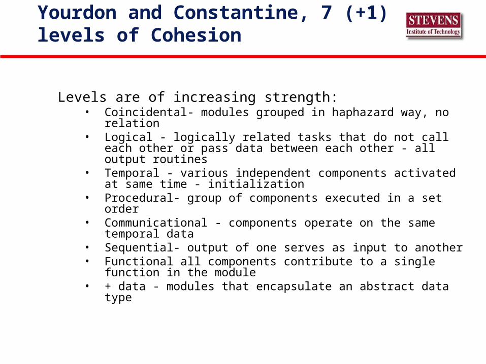
Yourdon and Constantine, 7 (+1) levels of Cohesion
Levels are of increasing strength:• Coincidental- modules grouped in haphazard way, no relation• Logical - logically related tasks that do not call each other or
pass data between each other - all output routines• Temporal - various independent components activated at same
time - initialization• Procedural- group of components executed in a set order• Communicational - components operate on the same temporal
data• Sequential- output of one serves as input to another• Functional all components contribute to a single function in the
module• + data - modules that encapsulate an abstract data type
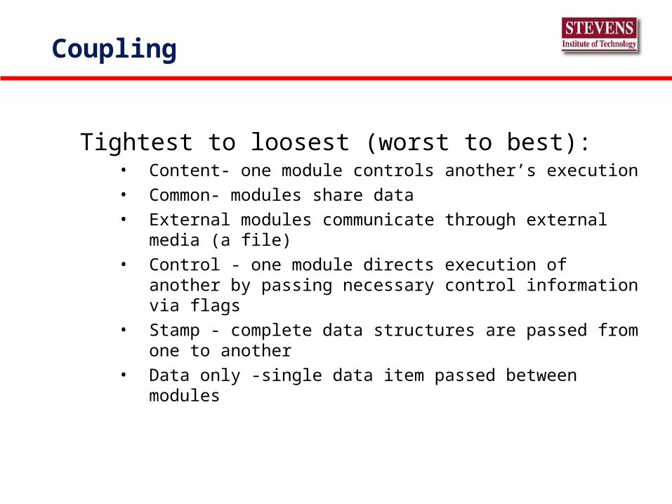
Coupling
Tightest to loosest (worst to best):• Content- one module controls another’s execution
• Common- modules share data
• External modules communicate through external media (a file)
• Control - one module directs execution of another by passing necessary control information via flags
• Stamp - complete data structures are passed from one to another
• Data only -single data item passed between modules
Coupling and cohesion
Advantages of low coupling, high cohesion:• Communication between developers is easier
• Correctness proofs are easy to derive and sustain
• Changes will not affect other modules, lower maintenance costs
• Reusability is increased
• Understanding increase
• Empirical data shows less errors.
Complexity
Attributes of the software that affect effort needed to construct or change a piece of software
2 classes of complexity metrics• Size based - KLOC
• Structure based - complicated control or data structures
Halstead and McCabe
System Structure
Types of intermodule relations such as A contains B, A follows B, A delivers data to B, A uses B
The amount of knowledge each uses about the other should be kept to a minimum• Information flow should be limited to procedure calls - no
Common data structures
Graph depicting procedure calls is a call graph - we can measure attributes related to the shape of the call graph
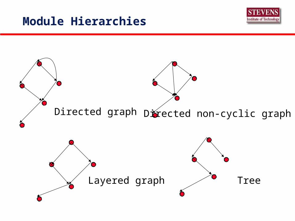
Module Hierarchies
Directed graph Directed non-cyclic graph
Layered graph Tree
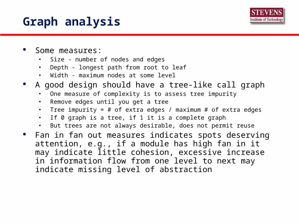
Graph analysis
Some measures:• Size - number of nodes and edges• Depth - longest path from root to leaf• Width - maximum nodes at some level
A good design should have a tree-like call graph• One measure of complexity is to assess tree impurity• Remove edges until you get a tree• Tree impurity = # of extra edges / maximum # of extra edges• If 0 graph is a tree, if 1 it is a complete graph• But trees are not always desirable, does not permit reuse
Fan in fan out measures indicates spots deserving attention, e.g., if a module has high fan in it may indicate little cohesion, excessive increase in information flow from one level to next may indicate missing level of abstraction
Design Heuristics for Modularity(Pressman)
Evaluate the first iteration of a program structure to reduce coupling and improve cohesion
Attempt to minimize structures with high fan out; strive for high fan in as depth increases
Keep the scope of effect of a module within the scope of control of that module
Evaluate module interfaces to reduce complexity and redundancy and improve consistency
Define modules whose function is predictable, but avoid modules that are overly restrictive
Strive for controlled entry modules by avoiding pathological conditions (branches or references into the middle of a module)
Design Methods
Functional decomposition Data flow design - functional decomposition with
respect to flow of data. Component is a black box transforming some input stream to an output stream
Design based on data structures - given a correct model of data structures, design of the program is straightforward
Object-oriented design
Functional Decomposition
Intended function decomposed into sub functions and continues downward
Start from user end it is top-down, primitives, bottom-up Parnas method:
• Identify sub systems, start with a minimal subset and define minimal extensions (incremental development)
• Apply information hiding principles• Define extensions step by step• Apply uses relation and try to develop a hierarchy• Layered approach, use only components at the same
or lower level
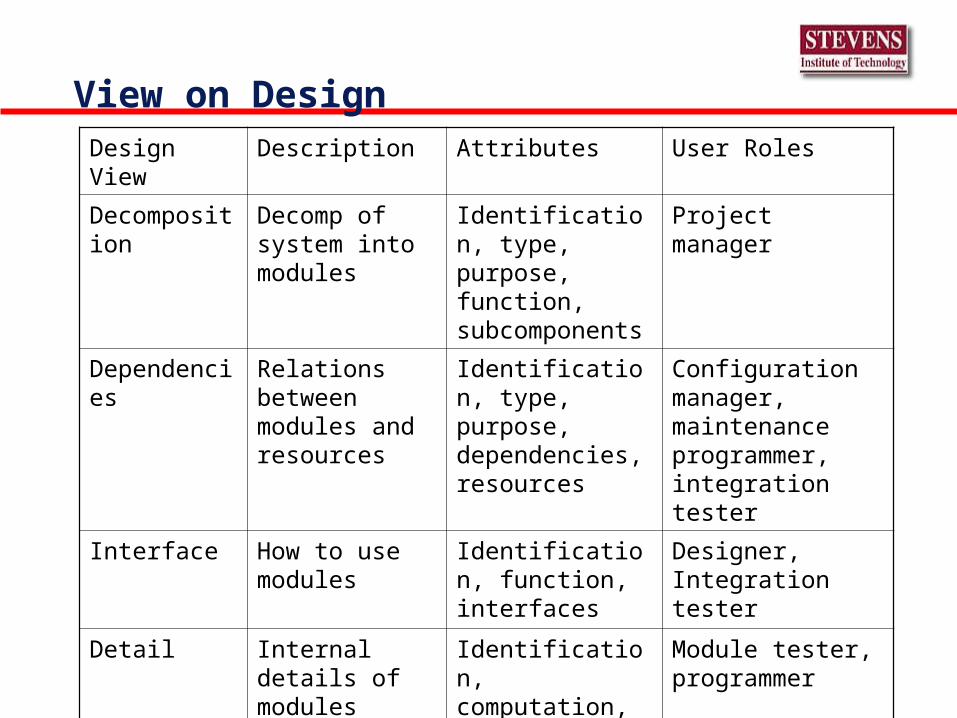
View on DesignDesign View Description Attributes User Roles
Decomposition Decomp of system into modules
Identification, type, purpose, function, subcomponents
Project manager
Dependencies Relations between modules and resources
Identification, type, purpose, dependencies, resources
Configuration manager, maintenance programmer, integration tester
Interface How to use modules
Identification, function, interfaces
Designer, Integration tester
Detail Internal details of modules
Identification, computation, data
Module tester, programmer
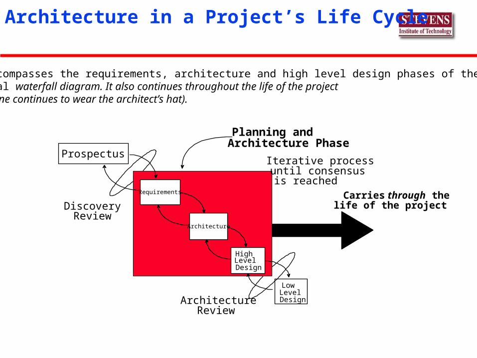
Architecture in a Project’s Life Cycle
Discovery
Planning and
ArchitectureReview
Review
Carries through thelife of the project
Iterative processuntil consensusis reached
Architecture PhaseProspectus
Requirements
Architecture
HighLevelDesign
LowLevelDesign
It encompasses the requirements, architecture and high level design phases of thetypical waterfall diagram. It also continues throughout the life of the project(someone continues to wear the architect’s hat).
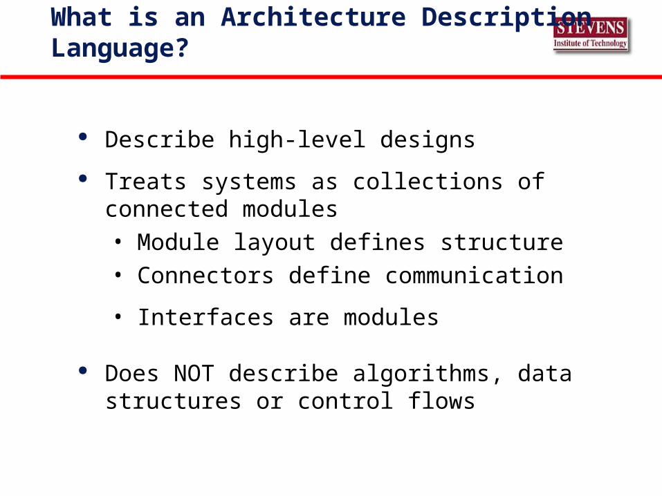
What is an Architecture Description Language?
Describe high-level designs
Treats systems as collections of connected modules
• Module layout defines structure
• Connectors define communication
• Interfaces are modules
Does NOT describe algorithms, data structures or control flows
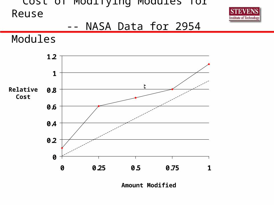
Cost of Modifying Modules for Reuse -- NASA Data for 2954 Modules
0
0.2
0.4
0.6
0.8
1
1.2
0 0.25 0.5 0.75 1
Usual LinearAssumption
Real Cost
Amount Modified
RelativeCost
OO Analysis and Design
Traditional techniques focus on functions of the system OO focuses on identifying and interrelating the objects
that play a role in the system Convergence to UML, Unified Modeling Language,
Booch, Jacobson and Rumbaugh Heuristic thoughts- keep objects simple and each method
should send messages to objects of a very limited set of classes (more when we explore OO metrics)
“Schools” of OO
European school, influenced by the Scandinavian school of Programming, OO analysis and design is modeling real world objects both animate and inanimate
American school, OO focuses on data abstraction and component reuse - identifying reusable components and building an inheritance hierarchy.
“What matters is not how closely we model today’s reality but how extensible and reusable our software is”
OO views
Modeling view - conceptual model of some part of a real or imaginary world.
Object = identity + state + behavior Philosophical view - objects are existential
abstractions and if not instantiated they cannot be changed
Software Engineering view - data abstractions encapsulate data and operations
OO views - 2
Implementation view• Continuous structure in memory, a record of data and code
elements
Formal viewpoint• Object viewed as a state machine with a finite set of states and a
finite set of state functions. State functions map old states and inputs to new states and inputs
Tensions exist betweenthe problem oriented (architecture) and the solution oriented view (design).
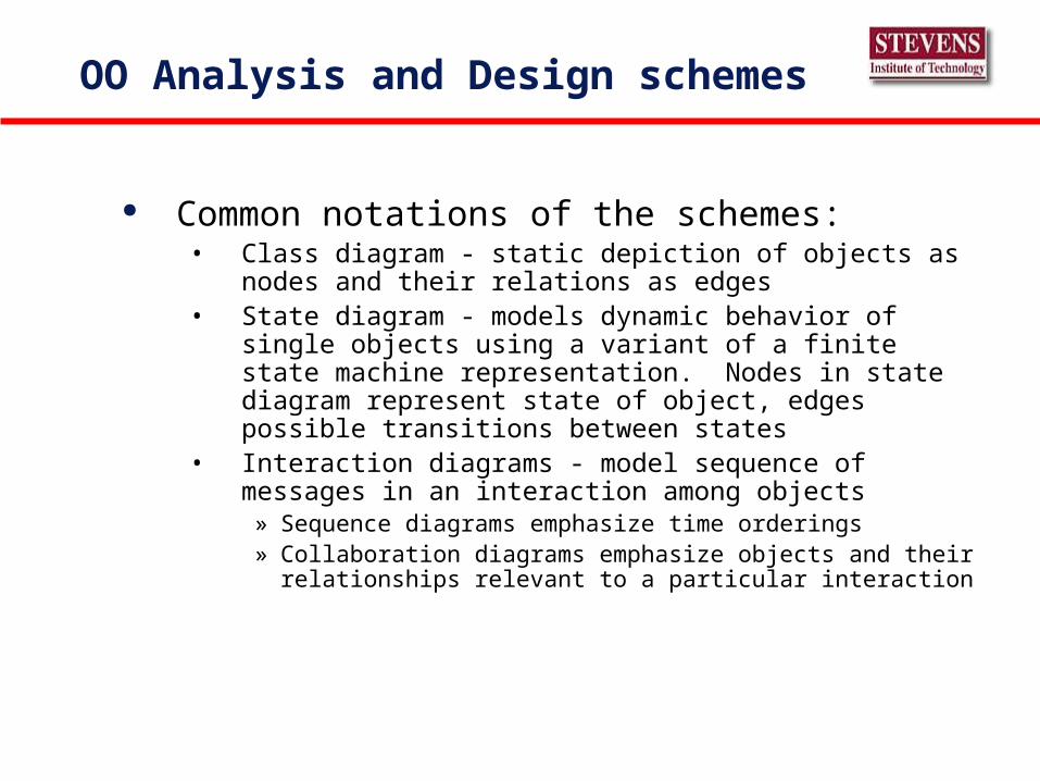
OO Analysis and Design schemes
Common notations of the schemes:• Class diagram - static depiction of objects as nodes and their relations
as edges• State diagram - models dynamic behavior of single objects using a
variant of a finite state machine representation. Nodes in state diagram represent state of object, edges possible transitions between states
• Interaction diagrams - model sequence of messages in an interaction among objects
» Sequence diagrams emphasize time orderings» Collaboration diagrams emphasize objects and their relationships relevant to
a particular interaction
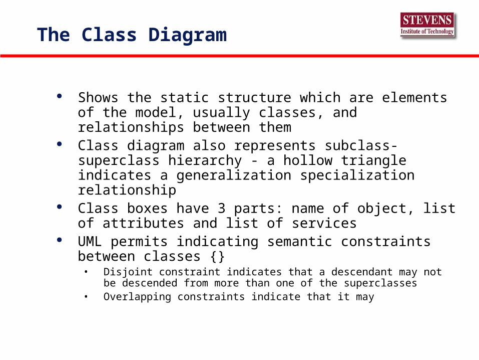
The Class Diagram
Shows the static structure which are elements of the model, usually classes, and relationships between them
Class diagram also represents subclass-superclass hierarchy - a hollow triangle indicates a generalization specialization relationship
Class boxes have 3 parts: name of object, list of attributes and list of services
UML permits indicating semantic constraints between classes {}
• Disjoint constraint indicates that a descendant may not be descended from more than one of the superclasses
• Overlapping constraints indicate that it may
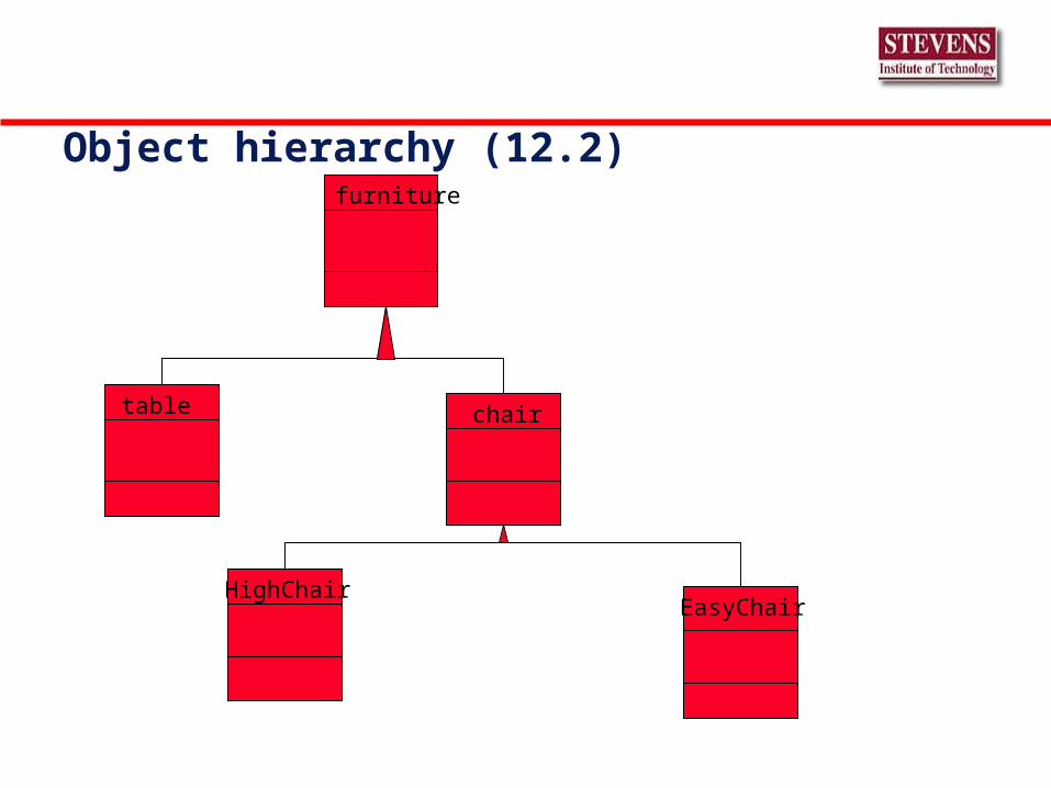
Object hierarchy (12.2)furniture
table chair
HighChairEasyChair
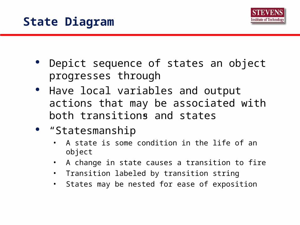
State Diagram
Depict sequence of states an object progresses through
Have local variables and output actions that may be associated with both transitions and states
“Statesmanship”• A state is some condition in the life of an object
• A change in state causes a transition to fire
• Transition labeled by transition string
• States may be nested for ease of exposition
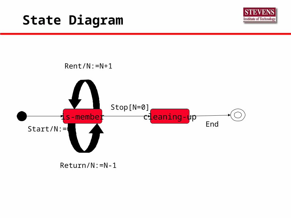
State Diagram
is-member cleaning-up
Start/N:=0
Rent/N:=N+1
Return/N:=N-1
Stop[N=0]
End
Sequence Diagram
Shows time ordering of messages Diagrams can become quite elaborate showing
asynchronous and synchronous message passing, indicate iteration, …
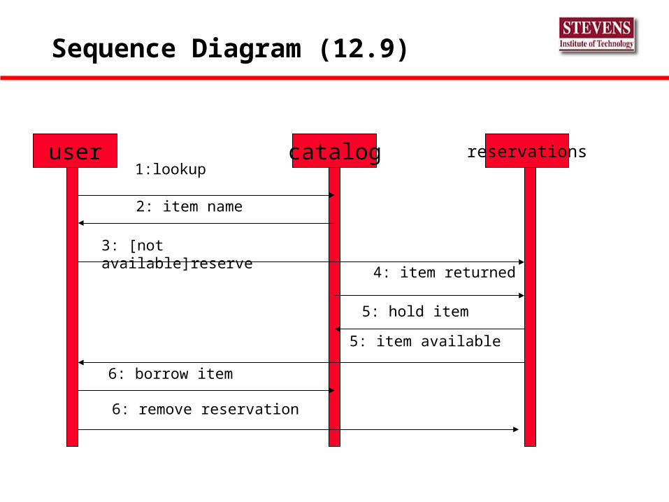
Sequence Diagram (12.9)
user reservationscatalog1:lookup
2: item name
3: [not available]reserve
4: item returned
5: hold item
5: item available
6: borrow item
6: remove reservation
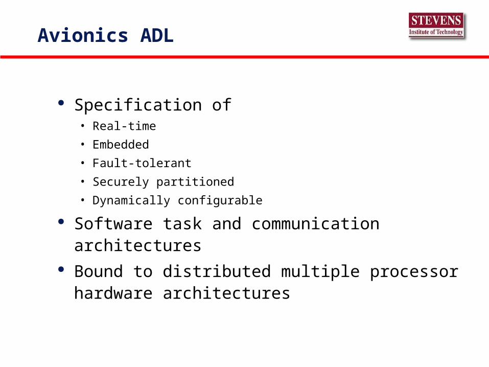
Avionics ADL
Specification of• Real-time
• Embedded
• Fault-tolerant
• Securely partitioned
• Dynamically configurable
Software task and communication architectures Bound to distributed multiple processor hardware
architectures
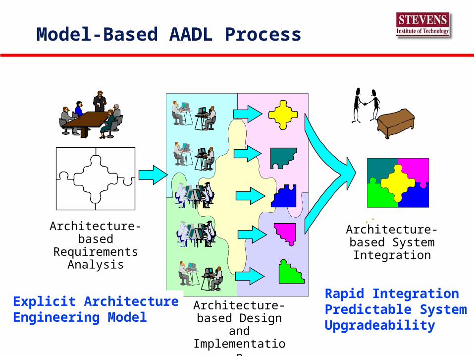
Architecture-based Requirements
Analysis
Architecture-based Design and
Implementation
Architecture-based System Integration
Model-Based AADL Process
Rapid Integration Predictable System Upgradeability
Explicit ArchitectureEngineering Model
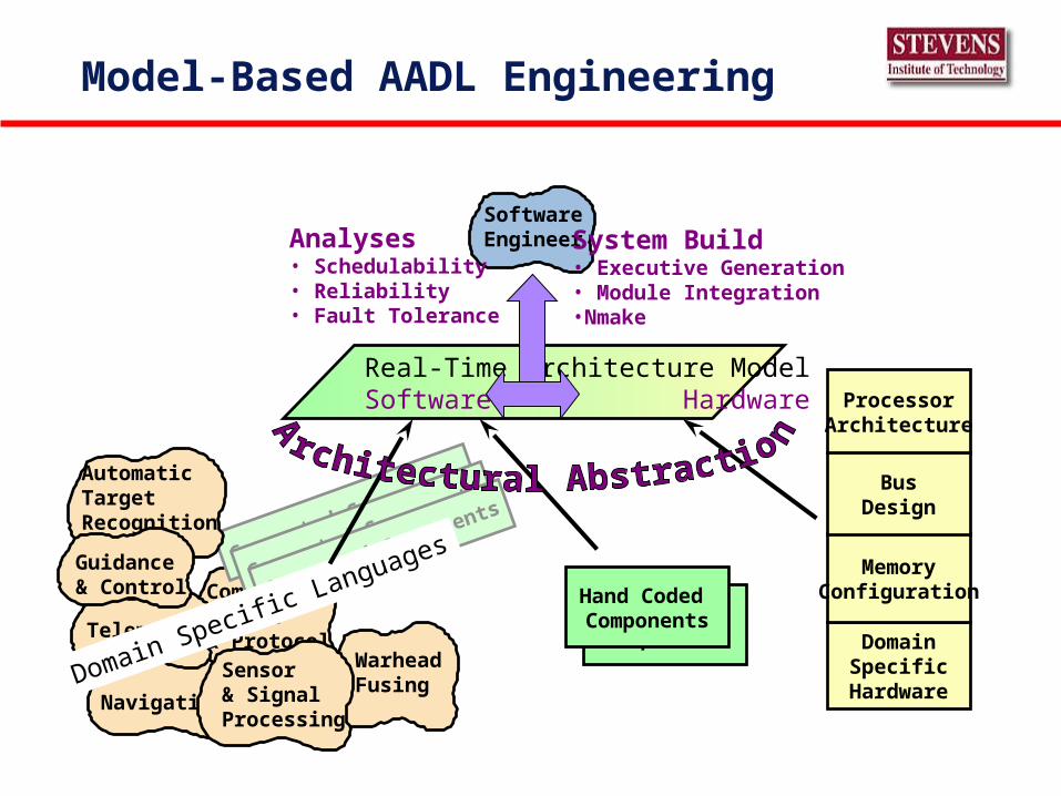
Navigation
WarheadFusing
Communi-cation& ProtocolTelemetry
Sensor& SignalProcessing
SoftwareEngineer
Real-Time Architecture ModelSoftware Hardware
System Build• Executive Generation• Module Integration•Nmake
DomainSpecific
Hardware
MemoryConfiguration
BusDesign
ProcessorArchitecture
Model-Based AADL Engineering
Generated Components
Generated Components
Generated Components
AutomaticTargetRecognition
Guidance& Control
Domain Specific Languages
Hand Coded Components
Hand Coded Components
Analyses• Schedulability• Reliability• Fault Tolerance
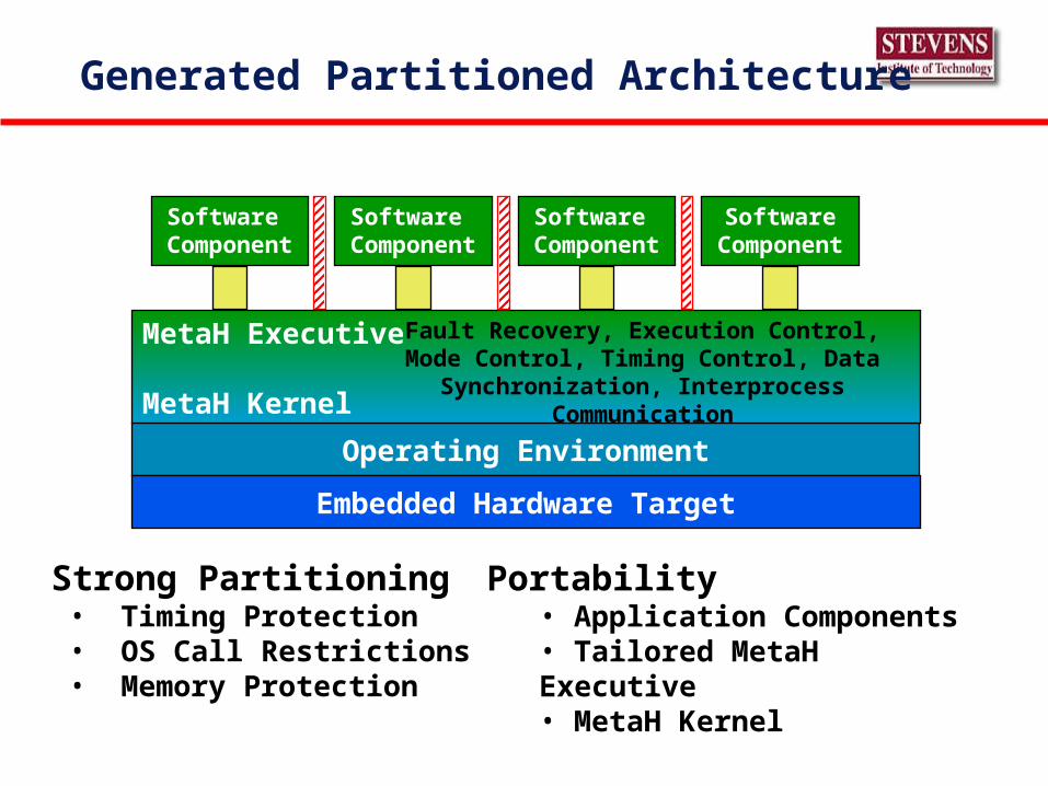
Generated Partitioned Architecture
Strong Partitioning • Timing Protection• OS Call Restrictions• Memory Protection
Portability• Application Components• Tailored MetaH Executive• MetaH Kernel
Operating Environment
Software Component
Software Component
Software Component
Embedded Hardware Target
SoftwareComponent
MetaH Executive
MetaH Kernel
Fault Recovery, Execution Control, Mode Control, Timing Control, Data Synchronization,
Interprocess Communication
UML Extensions
UML core concepts can be extended or specialized by users
• Three built-in extension mechanisms
»Stereotype
»Constraint
»Tagged Value
Key Design Constraints
Limit the language features Insist on Structured Programming Modularity and Componentry Provide Fault Containment and Recovery Restrict Module Size Perform scenario tests
Probably the most significant step forward in defect removal prior to delivery which we have yet experienced The evidence suggests that they are 5-10 times more efficient
than any other form of defect removal.
The technology is mature, (some 20 years old), and in trained hands, exceptionally effective.
Inspections

Conditions That Cause Software Instability
Poor Algorithms Missing Deadlines Round-off Error Build Up Memory Leaks Broken Pointers Register Misuse
Software Rejuvenation
Instead of running a system for a year, run it for one day 365 times
-- Periodic preemptive rollback of continuously running applications prevents future
failures.
-- Gracefully terminating an application allows restarting at a known and clean internal
state.