Embed Size (px)
Citation preview
LED Versorger Relco / VLM 2018
113
Intr
od
uzi
on
e -
Un
der
pro
du
ctio
nC
om
po
nen
ts
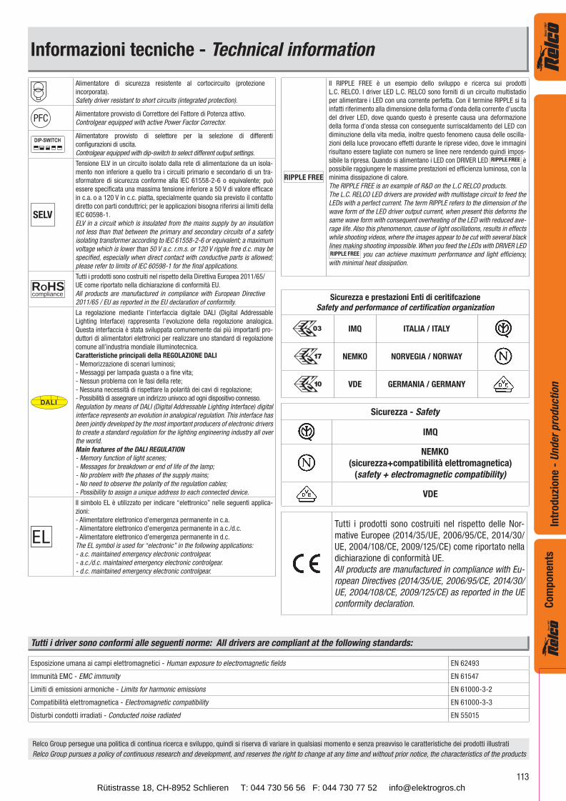
Informazioni tecniche - Technical information
Alimentatore di sicurezza resistente al cortocircuito (protezione
incorporata).
Safety driver resistant to short circuits (integrated protection).
PFCAlimentatore provvisto di Correttore del Fattore di Potenza attivo.
Controlgear equipped with active Power Factor Corrector.
Alimentatore provvisto di selettore per la selezione di differenti
configurazioni di uscita.
Controlgear equipped with dip-switch to select different output settings.
SELV
Tensione ELV in un circuito isolato dalla rete di alimentazione da un isola-
mento non inferiore a quello tra i circuiti primario e secondario di un tra-
sformatore di sicurezza conforme alla IEC 61558-2-6 o equivalente; può
essere specificata una massima tensione inferiore a 50 V di valore efficace
in c.a. o a 120 V in c.c. piatta, specialmente quando sia previsto il contatto
diretto con parti conduttrici; per le applicazioni bisogna riferirsi ai limiti della
IEC 60598-1.
ELV in a circuit which is insulated from the mains supply by an insulation
not less than that between the primary and secondary circuits of a safety
isolating transformer according to IEC 61558-2-6 or equivalent; a maximum
voltage which is lower than 50 V a.c. r.m.s. or 120 V ripple free d.c. may be
specified, especially when direct contact with conductive parts is allowed;
please refer to limits of IEC 60598-1 for the final applications.
ROHScompliance
Tutti i prodotti sono costruiti nel rispetto della Direttiva Europea 2011/65/
UE come riportato nella dichiarazione di conformità EU.
All products are manufactured in compliance with European Directive
2011/65 / EU as reported in the EU declaration of conformity.
DALI
La regolazione mediante l’interfaccia digitale DALI (Digital Addressable
Lighting Interface) rappresenta l’evoluzione della regolazione analogica.
Questa interfaccia è stata sviluppata comunemente dai più importanti pro-
duttori di alimentatori elettronici per realizzare uno standard di regolazione
comune all’industria mondiale illuminotecnica.
Caratteristiche principali della REGOLAZIONE DALI
- Memorizzazione di scenari luminosi;
- Messaggi per lampada guasta o a fine vita;
- Nessun problema con le fasi della rete;
- Nessuna necessità di rispettare la polarità dei cavi di regolazione;
- Possibilità di assegnare un indirizzo univoco ad ogni dispositivo connesso.
Regulation by means of DALI (Digital Addressable Lighting Interface) digital
interface represents an evolution in analogical regulation. This interface has
been jointly developed by the most important producers of electronic drivers
to create a standard regulation for the lighting engineering industry all over
the world.
Main features of the DALI REGULATION
- Memory function of light scenes;
- Messages for breakdown or end of life of the lamp;
- No problem with the phases of the supply mains;
- No need to observe the polarity of the regulation cables;
- Possibility to assign a unique address to each connected device.
Il simbolo EL è utilizzato per indicare “elettronico” nelle seguenti applica-
zioni:
- Alimentatore elettronico d’emergenza permanente in c.a.
- Alimentatore elettronico d’emergenza permanente in a.c./d.c.
- Alimentatore elettronico d’emergenza permanente in d.c.
The EL symbol is used for “electronic” in the following applications:
- a.c. maintained emergency electronic controlgear.
- a.c./d.c. maintained emergency electronic controlgear.
- d.c. maintained emergency electronic controlgear.
RIPPLE FREE
Il RIPPLE FREE è un esempio dello sviluppo e ricerca sui prodotti
L.C. RELCO. I driver LED L.C. RELCO sono forniti di un circuito multistadio
per alimentare i LED con una corrente perfetta. Con il termine RIPPLE si fa
infatti riferimento alla dimensione della forma d’onda della corrente d’uscita
del driver LED, dove quando questo è presente causa una deformazione
della forma d’onda stessa con conseguente surriscaldamento del LED con
diminuzione della vita media, inoltre questo fenomeno causa delle oscilla-
zioni della luce provocano effetti durante le riprese video, dove le immagini
risultano essere tagliate con numero se linee nere rendendo quindi impos-
sibile la ripresa. Quando si alimentano i LED con DRIVER LED RIPPLE FREE è
possibile raggiungere le massime prestazioni ed efficienza luminosa, con la
minima dissipazione di calore.
The RIPPLE FREE is an example of R&D on the L.C RELCO products.
The L.C. RELCO LED drivers are provided with multistage circuit to feed the
LEDs with a perfect current. The term RIPPLE refers to the dimension of the
wave form of the LED driver output current, when present this deforms the
same wave form with consequent overheating of the LED with reduced ave-
rage life. Also this phenomenon, cause of light oscillations, results in effects
while shooting videos, where the images appear to be cut with several black
lines making shooting impossible. When you feed the LEDs with DRIVER LED RIPPLE FREE you can achieve maximum performance and light efficiency,
with minimal heat dissipation.
Esposizione umana ai campi elettromagnetici - Human exposure to electromagnetic fields EN 62493
Immunità EMC - EMC immunity EN 61547
Limiti di emissioni armoniche - Limits for harmonic emissions EN 61000-3-2
Compatibilità elettromagnetica - Electromagnetic compatibility EN 61000-3-3
Disturbi condotti irradiati - Conducted noise radiated EN 55015
Tutti i driver sono conformi alle seguenti norme: All drivers are compliant at the following standards:
Relco Group persegue una politica di continua ricerca e sviluppo, quindi si riserva di variare in qualsiasi momento e senza preavviso le caratteristiche dei prodotti illustrati
Relco Group pursues a policy of continuous research and development, and reserves the right to change at any time and without prior notice, the characteristics of the products
Sicurezza e prestazioni Enti di ceritifcazione
Safety and performance of certification organization
IMQ ITALIA / ITALY
NEMKO NORVEGIA / NORWAY
VDE GERMANIA / GERMANY
Sicurezza - Safety
IMQ
NEMKO
(sicurezza+compatibilità elettromagnetica)
(safety + electromagnetic compatibility)
VDE
Tutti i prodotti sono costruiti nel rispetto delle Nor-
mative Europee (2014/35/UE, 2006/95/CE, 2014/30/
UE, 2004/108/CE, 2009/125/CE) come riportato nella
dichiarazione di conformità UE.
All products are manufactured in compliance with Eu-
ropean Directives (2014/35/UE, 2006/95/CE, 2014/30/
UE, 2004/108/CE, 2009/125/CE) as reported in the UE
conformity declaration.
Rütistrasse 18, CH-8952 Schlieren T: 044 730 56 56 F: 044 730 77 52 [email protected]
114
Ali
men
tato
ri L
ED
- S
tris
ce L
ED
- L
ED
Dri
ver
- S
trip
LE
DC
om
pon
ents
Pag.Articolo
Article
Codice
CodeW
Regolabile - Dimmable Tensione Vdc (VTD) - Voltage Vdc (CTD)
Pulsante
Push0÷10Vdc L/C 10 12 24
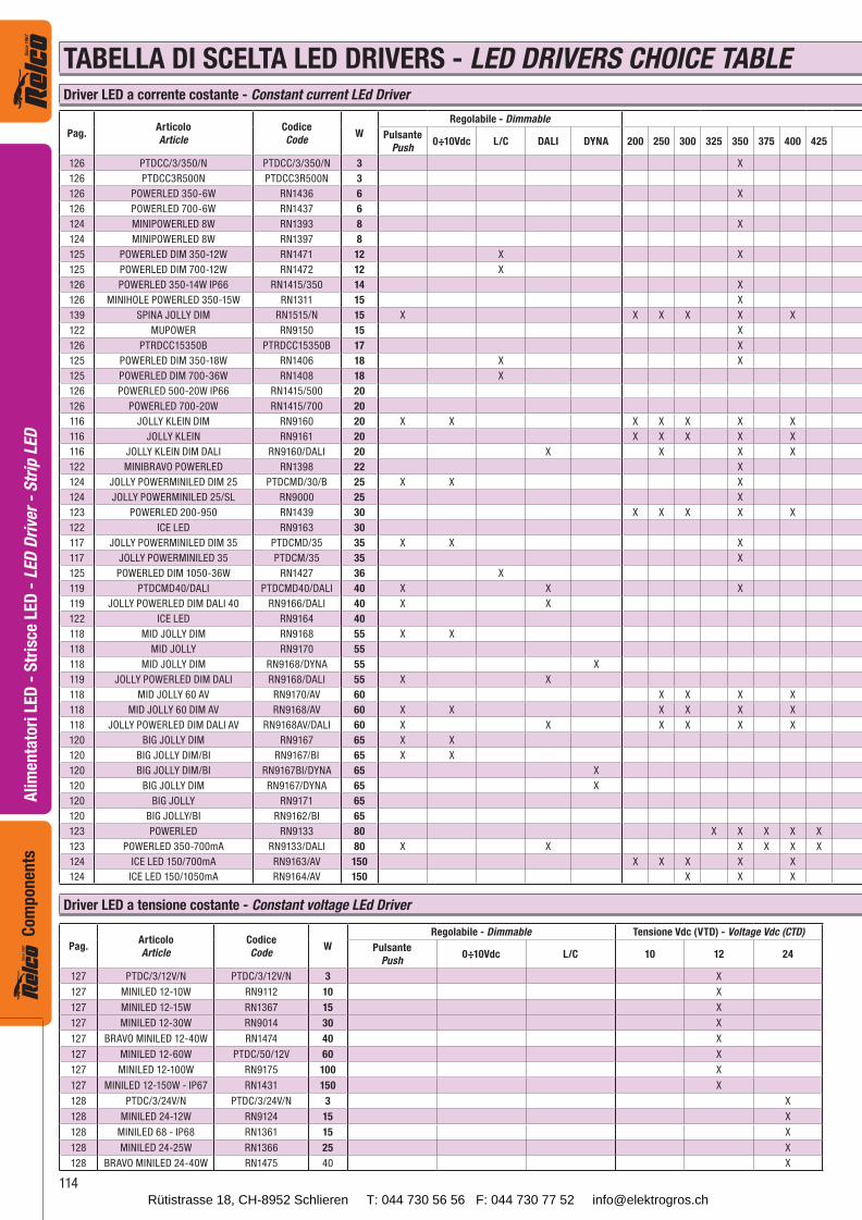
127 PTDC/3/12V/N PTDC/3/12V/N 3 X
127 MINILED 12-10W RN9112 10 X
127 MINILED 12-15W RN1367 15 X
127 MINILED 12-30W RN9014 30 X
127 BRAVO MINILED 12-40W RN1474 40 X
127 MINILED 12-60W PTDC/50/12V 60 X
127 MINILED 12-100W RN9175 100 X
127 MINILED 12-150W - IP67 RN1431 150 X
128 PTDC/3/24V/N PTDC/3/24V/N 3 X
128 MINILED 24-12W RN9124 15 X
128 MINILED 68 - IP68 RN1361 15 X
128 MINILED 24-25W RN1366 25 X
128 BRAVO MINILED 24-40W RN1475 40 X
Pag.Articolo
Article
Codice
CodeW
Regolabile - Dimmable
Pulsante
Push0÷10Vdc L/C DALI DYNA 200 250 300 325 350 375 400 425
126 PTDCC/3/350/N PTDCC/3/350/N 3 X
126 PTDCC3R500N PTDCC3R500N 3
126 POWERLED 350-6W RN1436 6 X
126 POWERLED 700-6W RN1437 6
124 MINIPOWERLED 8W RN1393 8 X
124 MINIPOWERLED 8W RN1397 8
125 POWERLED DIM 350-12W RN1471 12 X X
125 POWERLED DIM 700-12W RN1472 12 X
126 POWERLED 350-14W IP66 RN1415/350 14 X
126 MINIHOLE POWERLED 350-15W RN1311 15 X
139 SPINA JOLLY DIM RN1515/N 15 X X X X X X
122 MUPOWER RN9150 15 X
126 PTRDCC15350B PTRDCC15350B 17 X
125 POWERLED DIM 350-18W RN1406 18 X X
125 POWERLED DIM 700-36W RN1408 18 X
126 POWERLED 500-20W IP66 RN1415/500 20
126 POWERLED 700-20W RN1415/700 20
116 JOLLY KLEIN DIM RN9160 20 X X X X X X X
116 JOLLY KLEIN RN9161 20 X X X X X
116 JOLLY KLEIN DIM DALI RN9160/DALI 20 X X X X
122 MINIBRAVO POWERLED RN1398 22 X
124 JOLLY POWERMINILED DIM 25 PTDCMD/30/B 25 X X X
124 JOLLY POWERMINILED 25/SL RN9000 25 X
123 POWERLED 200-950 RN1439 30 X X X X X
122 ICE LED RN9163 30
117 JOLLY POWERMINILED DIM 35 PTDCMD/35 35 X X X
117 JOLLY POWERMINILED 35 PTDCM/35 35 X
125 POWERLED DIM 1050-36W RN1427 36 X
119 PTDCMD40/DALI PTDCMD40/DALI 40 X X X
119 JOLLY POWERLED DIM DALI 40 RN9166/DALI 40 X X
122 ICE LED RN9164 40
118 MID JOLLY DIM RN9168 55 X X
118 MID JOLLY RN9170 55
118 MID JOLLY DIM RN9168/DYNA 55 X
119 JOLLY POWERLED DIM DALI RN9168/DALI 55 X X
118 MID JOLLY 60 AV RN9170/AV 60 X X X X
118 MID JOLLY 60 DIM AV RN9168/AV 60 X X X X X X
118 JOLLY POWERLED DIM DALI AV RN9168AV/DALI 60 X X X X X X
120 BIG JOLLY DIM RN9167 65 X X
120 BIG JOLLY DIM/BI RN9167/BI 65 X X
120 BIG JOLLY DIM/BI RN9167BI/DYNA 65 X
120 BIG JOLLY DIM RN9167/DYNA 65 X
120 BIG JOLLY RN9171 65
120 BIG JOLLY/BI RN9162/BI 65
123 POWERLED RN9133 80 X X X X X
123 POWERLED 350-700mA RN9133/DALI 80 X X X X X X
124 ICE LED 150/700mA RN9163/AV 150 X X X X X
124 ICE LED 150/1050mA RN9164/AV 150 X X X
TABELLA DI SCELTA LED DRIVERS - LED DRIVERS CHOICE TABLEDriver LED a corrente costante - Constant current LEd Driver
Driver LED a tensione costante - Constant voltage LEd Driver
Rütistrasse 18, CH-8952 Schlieren T: 044 730 56 56 F: 044 730 77 52 [email protected]
115
Ali
men
tato
ri L
ED
- S
tris
ce L
ED
- L
ED
Dri
ver
- S
trip
LE
DC
om
po
nen
ts
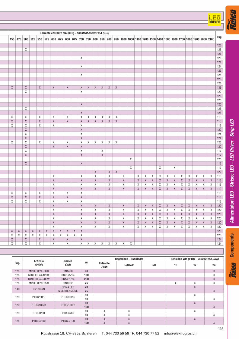
Corrente costante mA (CTD) - Constant current mA (CTD)
Pag450 475 500 525 550 575 600 625 650 675 700 750 800 850 900 950 1000 1050 1100 1200 1300 1400 1500 1600 1700 1800 1900 2000 2100
126
X 126
126
X 126
124
X 124
125
X 125
126
126
X X X X X X X X X X X 139
X X 122
126
125
X 125
X 126
X 126
X X X X X X X X X X X 116
X X X X X X X X X X X 116
X X X X X 116
X X 122
X X 124
X X 124
X X X X X X X X X X X 123
X X X X 122
X X X 117
X X X 117
X 125
X X 119
X X X 119
X X X 122
X X X X X X X X X X X X X X X X 118
X X X X X X X X X X X X X X X X 118
X X X X X X X X X X X X X X X X 118
X X X X X X X X X X X X X X X X 119
X X X X X X 118
X X X X X X 118
X X X X X X 118
X X X X X X X X X X X X X X X X 120
X X X X X X X X X X X X X X X X 120
X X X X X X X X X X X X X X X X 120
X X X X X X X X X X X X X X X X 120
X X X X X X X X X X X X X X X X 120
X X X X X X X X X X X X X X X X 120
X X X X X X X X X X X 123
X X X X X X X X X X X 123
X X X X X X 124
X X X X X X X X X X X X X 124
Pag.Articolo
Article
Codice
CodeW
Regolabile - Dimmable Tensione Vdc (VTD) - Voltage Vdc (CTD)
Pulsante
Push0÷10Vdc L/C 10 12 24
128 MINILED 24-60W RN1428 60 X
128 MINILED 24-120W RN9175/24 120 X
128 MINILED 24-200W RN1431/24 200 X
128 MINILED 20-25W RN1392 25 X X X
140 RN1339/NSPINA LED
MULTITENSIONE
20 X
25 X
129 PTDC/80/B PTDC/80/B50 X
80 X
129 PTDC/100/B PTDC/100/B60 X
100 X
129 PTDCD/80 PTDCD/8050 X X X
80 X X X
128 PTDCD/100 PTDCD/10060 X X X
100 X X X
DRIVER
Rütistrasse 18, CH-8952 Schlieren T: 044 730 56 56 F: 044 730 77 52 [email protected]
116
Ali
men
tato
ri L
ED
- S
tris
ce L
ED
- L
ED
Dri
ver
- S
trip
LE
DC
om
pon
ents
ROHScompliance
PFCSELVCDT RIPPLE FREEDIMpush
DIM0-10
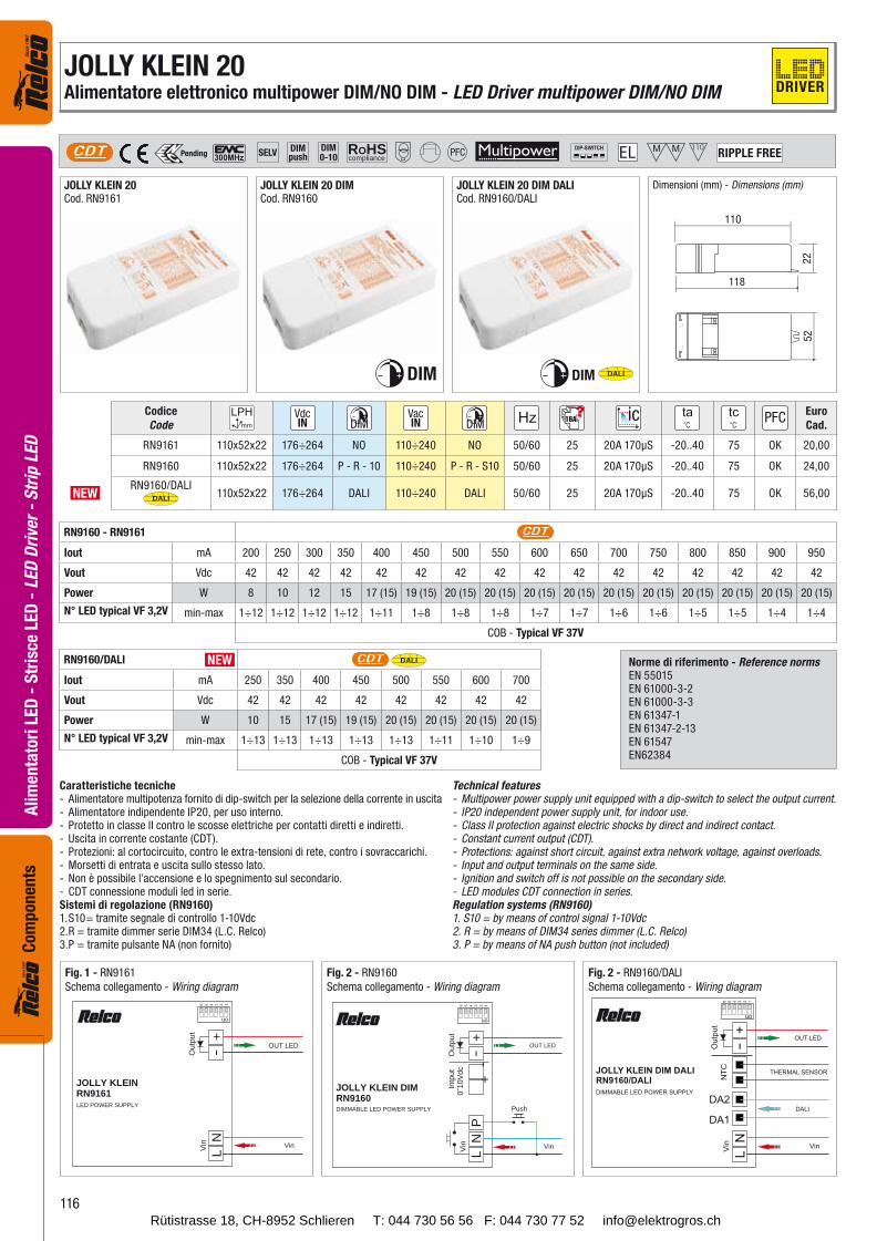
JOLLY KLEIN 20Cod. RN9161
Dimensioni (mm) - Dimensions (mm)
Codice
Code16A
Euro
Cad.
RN9161 110x52x22 176÷264 NO 110÷240 NO 50/60 25 20A 170μS -20..40 75 OK 20,00
RN9160 110x52x22 176÷264 P - R - 10 110÷240 P - R - S10 50/60 25 20A 170μS -20..40 75 OK 24,00
NEWRN9160/DALI
DALI 110x52x22 176÷264 DALI 110÷240 DALI 50/60 25 20A 170μS -20..40 75 OK 56,00
RN9160 - RN9161 CDT
Iout mA 200 250 300 350 400 450 500 550 600 650 700 750 800 850 900 950
Vout Vdc 42 42 42 42 42 42 42 42 42 42 42 42 42 42 42 42
Power W 8 10 12 15 17 (15) 19 (15) 20 (15) 20 (15) 20 (15) 20 (15) 20 (15) 20 (15) 20 (15) 20 (15) 20 (15) 20 (15)
N° LED typical VF 3,2V min-max 1÷12 1÷12 1÷12 1÷12 1÷11 1÷8 1÷8 1÷8 1÷7 1÷7 1÷6 1÷6 1÷5 1÷5 1÷4 1÷4
COB - Typical VF 37V
JOLLY KLEIN DIMRN9160DIMMABLE LED POWER SUPPLY
LN
-+
Vin
on
123456
P
-+
In
tput
0˜10
Vdc
Out
put
OUT LED
Vin
Push
JOLLY KLEIN RN9161
LED POWER SUPPLY
LN
-+
Vin
on123456
Out
put
OUT LED
Vin
118
110
22
52
DIM
JOLLY KLEIN 20 DIMCod. RN9160
JOLLY KLEIN 20 DIM DALICod. RN9160/DALI
DIM DALI
RN9160/DALI CDT DALI
Iout mA 250 350 400 450 500 550 600 700
Vout Vdc 42 42 42 42 42 42 42 42
Power W 10 15 17 (15) 19 (15) 20 (15) 20 (15) 20 (15) 20 (15)
N° LED typical VF 3,2V min-max 1÷13 1÷13 1÷13 1÷13 1÷13 1÷11 1÷10 1÷9
COB - Typical VF 37V
NEW
JOLLY KLEIN 20Alimentatore elettronico multipower DIM/NO DIM - LED Driver multipower DIM/NO DIM
Caratteristiche tecniche- Alimentatore multipotenza fornito di dip-switch per la selezione della corrente in uscita- Alimentatore indipendente IP20, per uso interno.- Protetto in classe II contro le scosse elettriche per contatti diretti e indiretti.- Uscita in corrente costante (CDT).- Protezioni: al cortocircuito, contro le extra-tensioni di rete, contro i sovraccarichi.- Morsetti di entrata e uscita sullo stesso lato.- Non è possibile l’accensione e lo spegnimento sul secondario.- CDT connessione moduli led in serie.Sistemi di regolazione (RN9160)1. S10 = tramite segnale di controllo 1-10Vdc2. R = tramite dimmer serie DIM34 (L.C. Relco)3. P = tramite pulsante NA (non fornito)
Technical features- Multipower power supply unit equipped with a dip-switch to select the output current.- IP20 independent power supply unit, for indoor use.- Class II protection against electric shocks by direct and indirect contact.- Constant current output (CDT).- Protections: against short circuit, against extra network voltage, against overloads.- Input and output terminals on the same side.- Ignition and switch off is not possible on the secondary side.- LED modules CDT connection in series.Regulation systems (RN9160)1. S10 = by means of control signal 1-10Vdc2. R = by means of DIM34 series dimmer (L.C. Relco)3. P = by means of NA push button (not included)
Fig. 2 - RN9160
Schema collegamento - Wiring diagram
Fig. 2 - RN9160/DALI
Schema collegamento - Wiring diagram
Fig. 1 - RN9161
Schema collegamento - Wiring diagram
Norme di riferimento - Reference normsEN 55015 EN 61000-3-2EN 61000-3-3EN 61347-1EN 61347-2-13EN 61547EN62384
DRIVER
Rütistrasse 18, CH-8952 Schlieren T: 044 730 56 56 F: 044 730 77 52 [email protected]
117
Ali
men
tato
ri L
ED
- S
tris
ce L
ED
- L
ED
Dri
ver
- S
trip
LE
DC
om
po
nen
ts
ROHScompliance PFCSELVCDT RIPPLE FREE
DIMpush
DIM0-10
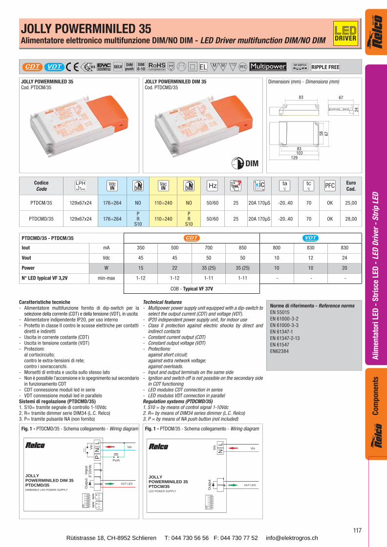
JOLLY POWERMINILED DIM 35Cod. PTDCMD/35
JOLLY POWERMINILED 35Cod. PTDCM/35
DIM
Dimensioni (mm) - Dimensions (mm)
24
58
67
6783
83103
129
Codice
Code16A
Euro
Cad.
PTDCM/35 129x67x24 176÷264 NO 110÷240 NO 50/60 25 20A 170μS -20..40 70 OK 25,00
PTDCMD/35 129x67x24 176÷264PR
S10110÷240
PR
S1050/60 25 20A 170μS -20..40 70 OK 28,00
PTDCMD/35 - PTDCM/35 CDT VDT
Iout mA 350 500 700 850 800 830 830
Vout Vdc 45 45 50 50 10 12 24
Power W 15 22 35 (25) 35 (25) 10 10 20
N° LED typical VF 3,2V min-max 1-12 1-12 1-11 1-11 - - -
COB - Typical VF 37V
JOLLY POWERMINILED 35Alimentatore elettronico multifunzione DIM/NO DIM - LED Driver multifunction DIM/NO DIM
VDT
Caratteristiche tecniche- Alimentatore multifunzione fornito di dip-switch per la selezione della corrente (CDT) e della tensione (VDT), in uscita- Alimentatore indipendente IP20, per uso interno- Protetto in classe II contro le scosse elettriche per contatti diretti e indiretti- Uscita in corrente costante (CDT)- Uscita in tensione costante (VDT)- Protezioni: al cortocircuito; contro le extra-tensioni di rete; contro i sovraccarichi.- Morsetti di entrata e uscita sullo stesso lato- Non è possibile l’accensione e lo spegnimento sul secondario in funzionamento CDT- CDT connessione moduli led in serie- VDT connessione moduli led in paralleloSistemi di regolazione (PTDCMD/35)1. S10 = tramite segnale di controllo 1-10Vdc2. R = tramite dimmer serie DIM34 (L.C. Relco)3. P = tramite pulsante NA (non fornito)
Technical features- Multipower power supply unit equipped with a dip-switch to select the output current (CDT) and voltage (VDT).- IP20 independent power supply unit, for indoor use- Class II protection against electric shocks by direct and indirect contacts- Constant current output (CDT)- Constant output voltage (VDT)- Protections: against short circuit; against extra network voltage; against overloads.- Input and output terminals on the same side- Ignition and switch off is not possible on the secondary side in CDT functioning- LED modules CDT connection in series- LED modules VDT connection in parallelRegulation systems (PTDCMD/35)1. S10 = by means of control signal 1-10Vdc2. R = by means of DIM34 series dimmer (L.C. Relco)3. P = by means of NA push button (not included)
Fig. 1 - PTDCMD/35 - Schema collegamento - Wiring diagram
JOLLYPOWERMINILED DIM 35PTDCMD/35DIMMABLE LED POWER SUPPLY
LNV
in
on 123456
P
-+
In
tput
0˜10
Vdc
Out
put
OUT LED
Vin
Push
-+
+-
+-
sync
sync
Fig. 1 - PTDCM/35 - Schema collegamento - Wiring diagram
JOLLYPOWERMINILED 35PTDCM/35LED POWER SUPPLY
LNV
in
on 123456
Out
put
OUT LED
Vin
-+
Norme di riferimento - Reference norms
EN 55015
EN 61000-3-2
EN 61000-3-3
EN 61347-1
EN 61347-2-13
EN 61547
EN62384
DRIVER
Rütistrasse 18, CH-8952 Schlieren T: 044 730 56 56 F: 044 730 77 52 [email protected]
118
Ali
men
tato
ri L
ED
- S
tris
ce L
ED
- L
ED
Dri
ver
- S
trip
LE
DC
om
pon
ents
ROHScompliance
PFCSELVCDT RIPPLE FREEDIMpush
DIM0-10
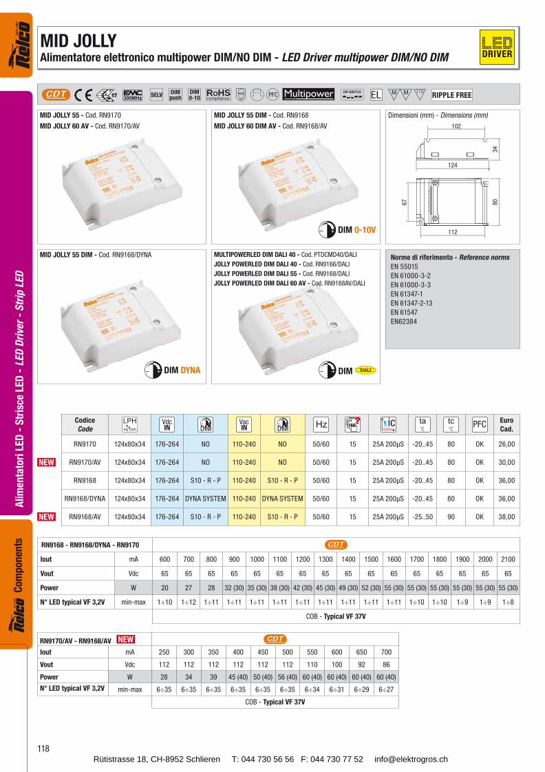
MID JOLLY 55 DIM - Cod. RN9168
MID JOLLY 60 DIM AV - Cod. RN9168/AV
DIM 0-10V
MID JOLLY 55 - Cod. RN9170
MID JOLLY 60 AV - Cod. RN9170/AV
124
112
102
34
80
67
MID JOLLY 55 DIM - Cod. RN9168/DYNA
DIM DYNA
Codice
Code16A
Euro
Cad.
RN9170 124x80x34 176-264 NO 110-240 NO 50/60 15 25A 200μS -20..45 80 OK 26,00
NEW RN9170/AV 124x80x34 176-264 NO 110-240 NO 50/60 15 25A 200μS -20..45 80 OK 30,00
RN9168 124x80x34 176-264 S10 - R - P 110-240 S10 - R - P 50/60 15 25A 200μS -20..45 80 OK 36,00
RN9168/DYNA 124x80x34 176-264 DYNA SYSTEM 110-240 DYNA SYSTEM 50/60 15 25A 200μS -20..45 80 OK 36,00
NEW RN9168/AV 124x80x34 176-264 S10 - R - P 110-240 S10 - R - P 50/60 15 25A 200μS -25..50 90 OK 38,00
RN9168 - RN9168/DYNA - RN9170 CDT
Iout mA 600 700 800 900 1000 1100 1200 1300 1400 1500 1600 1700 1800 1900 2000 2100
Vout Vdc 65 65 65 65 65 65 65 65 65 65 65 65 65 65 65 65
Power W 20 27 28 32 (30) 35 (30) 38 (30) 42 (30) 45 (30) 49 (30) 52 (30) 55 (30) 55 (30) 55 (30) 55 (30) 55 (30) 55 (30)
N° LED typical VF 3,2V min-max 1÷10 1÷12 1÷11 1÷11 1÷11 1÷11 1÷11 1÷11 1÷11 1÷11 1÷11 1÷10 1÷10 1÷9 1÷9 1÷8
COB - Typical VF 37V
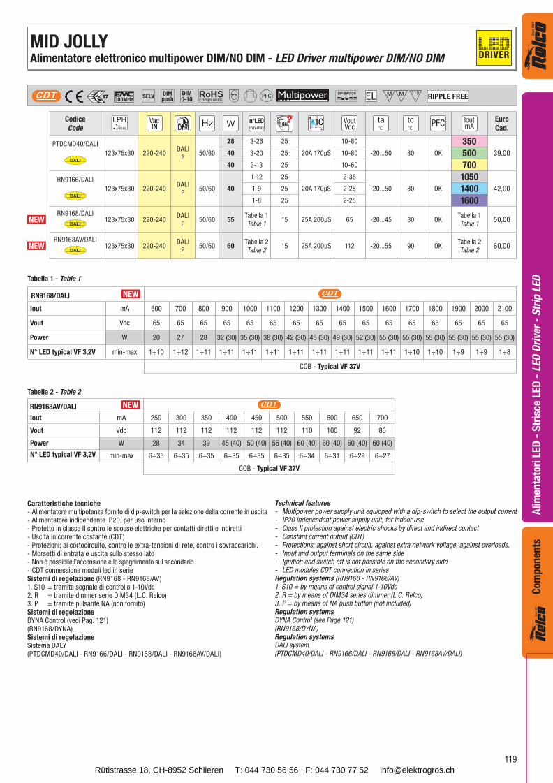
DIM DALI
MULTIPOWERLED DIM DALI 40 - Cod. PTDCMD40/DALI
JOLLY POWERLED DIM DALI 40 - Cod. RN9166/DALI
JOLLY POWERLED DIM DALI 55 - Cod. RN9168/DALI
JOLLY POWERLED DIM DALI 60 AV - Cod. RN9168AV/DALI
RN9170/AV - RN9168/AV NEW CDT
Iout mA 250 300 350 400 450 500 550 600 650 700
Vout Vdc 112 112 112 112 112 112 110 100 92 86
Power W 28 34 39 45 (40) 50 (40) 56 (40) 60 (40) 60 (40) 60 (40) 60 (40)
N° LED typical VF 3,2V min-max 6÷35 6÷35 6÷35 6÷35 6÷35 6÷35 6÷34 6÷31 6÷29 6÷27
COB - Typical VF 37V
Norme di riferimento - Reference norms
EN 55015
EN 61000-3-2
EN 61000-3-3
EN 61347-1
EN 61347-2-13
EN 61547
EN62384
Dimensioni (mm) - Dimensions (mm)
MID JOLLYAlimentatore elettronico multipower DIM/NO DIM - LED Driver multipower DIM/NO DIM DRIVER
Rütistrasse 18, CH-8952 Schlieren T: 044 730 56 56 F: 044 730 77 52 [email protected]
119
Ali
men
tato
ri L
ED
- S
tris
ce L
ED
- L
ED
Dri
ver
- S
trip
LE
DC
om
po
nen
ts
Codice
Coden°LEDmin-max
16A VoutVdc
IoutmA
Euro
Cad.
PTDCMD40/DALI
DALI123x75x30 220-240
DALI
P50/60
28 3-26 25
20A 170μS
10-80
-20...50 80 OK
350
39,0040 3-20 25 10-80 50040 3-13 25 10-60 700
RN9166/DALI
DALI123x75x30 220-240
DALI
P50/60 40
1-12 25
20A 170μS
2-38
-20...50 80 OK
1050
42,001-9 25 2-28 14001-8 25 2-25 1600
NEWRN9168/DALI
DALI123x75x30 220-240
DALI
P50/60 55
Tabella 1
Table 115 25A 200μS 65 -20...45 80 OK
Tabella 1
Table 150,00
NEWRN9168AV/DALI
DALI123x75x30 220-240
DALI
P50/60 60
Tabella 2
Table 215 25A 200μS 112 -20...55 90 OK
Tabella 2
Table 260,00
ROHScompliance
PFCSELVCDT RIPPLE FREEDIMpush
DIM0-10
RN9168/DALI NEW CDT
Iout mA 600 700 800 900 1000 1100 1200 1300 1400 1500 1600 1700 1800 1900 2000 2100
Vout Vdc 65 65 65 65 65 65 65 65 65 65 65 65 65 65 65 65
Power W 20 27 28 32 (30) 35 (30) 38 (30) 42 (30) 45 (30) 49 (30) 52 (30) 55 (30) 55 (30) 55 (30) 55 (30) 55 (30) 55 (30)
N° LED typical VF 3,2V min-max 1÷10 1÷12 1÷11 1÷11 1÷11 1÷11 1÷11 1÷11 1÷11 1÷11 1÷11 1÷10 1÷10 1÷9 1÷9 1÷8
COB - Typical VF 37V
RN9168AV/DALI NEW CDT
Iout mA 250 300 350 400 450 500 550 600 650 700
Vout Vdc 112 112 112 112 112 112 110 100 92 86
Power W 28 34 39 45 (40) 50 (40) 56 (40) 60 (40) 60 (40) 60 (40) 60 (40)
N° LED typical VF 3,2V min-max 6÷35 6÷35 6÷35 6÷35 6÷35 6÷35 6÷34 6÷31 6÷29 6÷27
COB - Typical VF 37V
Tabella 1 - Table 1
Tabella 2 - Table 2
Caratteristiche tecniche- Alimentatore multipotenza fornito di dip-switch per la selezione della corrente in uscita- Alimentatore indipendente IP20, per uso interno- Protetto in classe II contro le scosse elettriche per contatti diretti e indiretti- Uscita in corrente costante (CDT)- Protezioni: al cortocircuito, contro le extra-tensioni di rete, contro i sovraccarichi.- Morsetti di entrata e uscita sullo stesso lato- Non è possibile l’accensione e lo spegnimento sul secondario- CDT connessione moduli led in serieSistemi di regolazione (RN9168 - RN9168/AV)1. S10 = tramite segnale di controllo 1-10Vdc2. R = tramite dimmer serie DIM34 (L.C. Relco)3. P = tramite pulsante NA (non fornito)Sistemi di regolazioneDYNA Control (vedi Pag. 121)(RN9168/DYNA)Sistemi di regolazioneSistema DALY(PTDCMD40/DALI - RN9166/DALI - RN9168/DALI - RN9168AV/DALI)
Technical features- Multipower power supply unit equipped with a dip-switch to select the output current- IP20 independent power supply unit, for indoor use- Class II protection against electric shocks by direct and indirect contact- Constant current output (CDT)- Protections: against short circuit, against extra network voltage, against overloads.- Input and output terminals on the same side- Ignition and switch off is not possible on the secondary side- LED modules CDT connection in seriesRegulation systems (RN9168 - RN9168/AV)1. S10 = by means of control signal 1-10Vdc2. R = by means of DIM34 series dimmer (L.C. Relco)3. P = by means of NA push button (not included)Regulation systemsDYNA Control (see Page 121)(RN9168/DYNA)Regulation systemsDALI system(PTDCMD40/DALI - RN9166/DALI - RN9168/DALI - RN9168AV/DALI)
MID JOLLYAlimentatore elettronico multipower DIM/NO DIM - LED Driver multipower DIM/NO DIM DRIVER
Rütistrasse 18, CH-8952 Schlieren T: 044 730 56 56 F: 044 730 77 52 [email protected]
120
Ali
men
tato
ri L
ED
- S
tris
ce L
ED
- L
ED
Dri
ver
- S
trip
LE
DC
om
pon
ents
ROHScompliance
PFCSELVCDT RIPPLE FREEDIMpush
DIM0-10
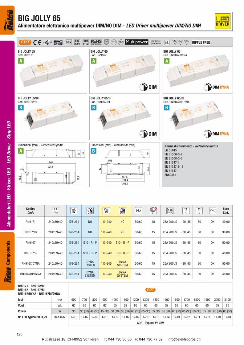
BIG JOLLY 65Cod. RN9171
BIG JOLLY 65/BICod. RN9162/BI
BIG JOLLY 65Cod. RN9167
BIG JOLLY 65/BICod. RN9167/BI
BIG JOLLY 65Cod. RN9167/DYNA
BIG JOLLY 65/BICod. RN9167BI/DYNA
DIM DYNA
DIM DYNA
225,6
240
43
,2
59
,23
5 40
Ø45
203,5
194,4
187,5
47
59,2
40
Ø45
A A A
B B B
A B
Codice
Code16A
Euro
Cad.
RN9171 240x59x40 176-264 NO 110-240 NO 50/60 15 25A 200μS -20..45 80 OK 40,00
RN9162/BI 204x59x40 176-264 NO 110-240 NO 50/60 15 25A 200μS -20..45 80 OK 38,00
RN9167 240x59x40 176-264 S10 - R - P 110-240 S10 - R - P 50/60 15 25A 200μS -20..45 80 OK 50,00
RN9167/BI 204x59x40 176-264 S10 - R - P 110-240 S10 - R - P 50/60 15 25A 200μS -20..45 80 OK 48,00
RN9167/DYNA 240x59x40 176-264DYNA
SYSTEM110-240
DYNASYSTEM
50/60 15 25A 200μS -20..45 80 OK 50,00
RN9167BI/DYNA 204x59x40 176-264DYNA
SYSTEM110-240
DYNASYSTEM
50/60 15 25A 200μS -20..45 80 OK 48,00
RN9171 - RN9162/BI
RN9167 - RN9167/BI
RN9167/DYNA - RN9167BI/DYNA
CDT
Iout mA 600 700 800 900 1000 1100 1200 1300 1400 1500 1600 1700 1800 1900 2000 2100
Vout Vdc 65 65 65 65 65 65 65 65 65 65 65 65 65 65 65 65
Power W 30 35 (30) 40 (30) 45 (30) 50 (30) 55 (30) 60 (30) 65 (30) 65 (30) 65 (30) 65 (30) 65 (30) 65 (30) 65 (30) 65 (30) 65 (30)
N° LED typical VF 3,2V min-max 1÷16 1÷16 1÷16 1÷16 1÷16 1÷16 1÷16 1÷16 1÷15 1÷14 1÷13 1÷12 1÷11 1÷11 1÷10 1÷10
COB - Typical VF 37V
DIM
DIM
Dimensioni (mm) - Dimensions (mm) Dimensioni (mm) - Dimensions (mm) Norme di riferimento - Reference norms
EN 55015
EN 61000-3-2
EN 61000-3-3
EN 61347-1
EN 61347-2-13
EN 61547
EN62384
BIG JOLLY 65Alimentatore elettronico multipower DIM/NO DIM - LED Driver multipower DIM/NO DIM DRIVER
Rütistrasse 18, CH-8952 Schlieren T: 044 730 56 56 F: 044 730 77 52 [email protected]
121
Ali
men
tato
ri L
ED
- S
tris
ce L
ED
- L
ED
Dri
ver
- S
trip
LE
DC
om
po
nen
ts
DYNA CONTROL
CLO - Constant Light Output
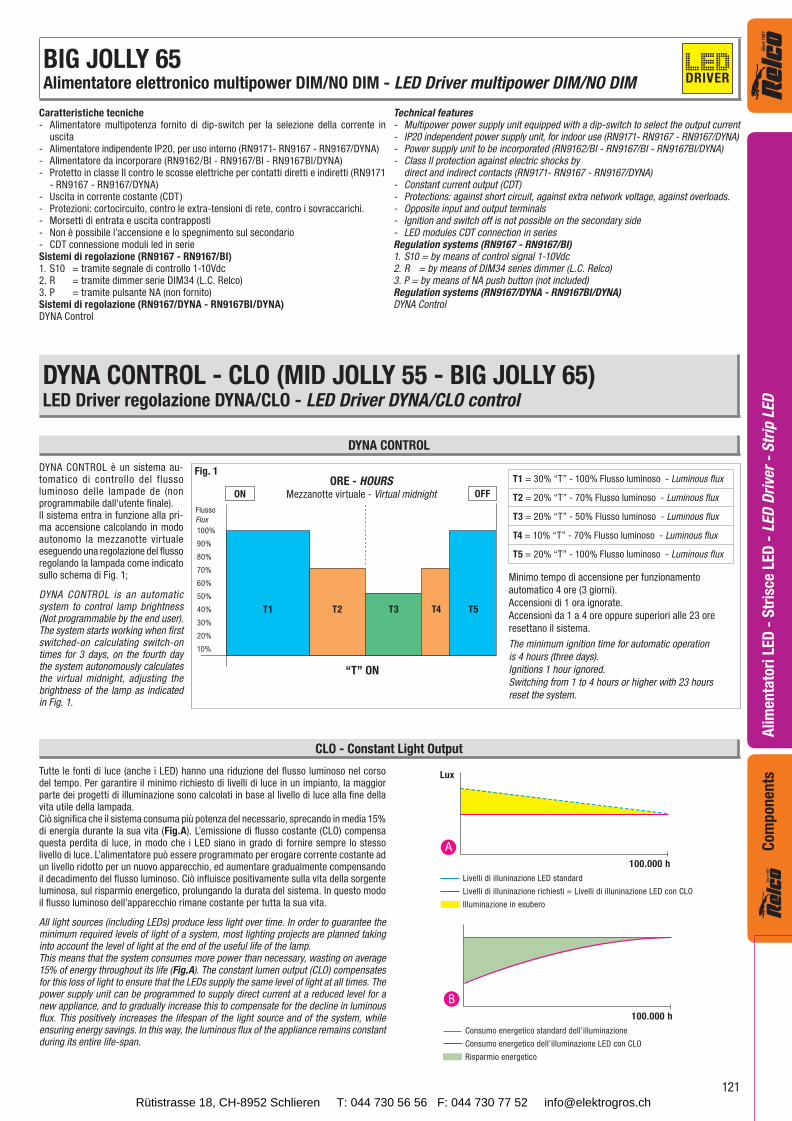
Livelli di illuninazione LED standard
Livelli di illuninazione richiesti = Livelli di illuninazione LED con CLO
Illuminazione in esubero
Lux
A100.000 h
Consumo energetico standard dell’illuminazione
Consumo energetico dell’illuminazione LED con CLO
Risparmio energetico
100.000 h
B
“T” ON
ON OFF
Caratteristiche tecniche- Alimentatore multipotenza fornito di dip-switch per la selezione della corrente in uscita- Alimentatore indipendente IP20, per uso interno (RN9171- RN9167 - RN9167/DYNA)- Alimentatore da incorporare (RN9162/BI - RN9167/BI - RN9167BI/DYNA)- Protetto in classe II contro le scosse elettriche per contatti diretti e indiretti (RN9171 - RN9167 - RN9167/DYNA)- Uscita in corrente costante (CDT)- Protezioni: cortocircuito, contro le extra-tensioni di rete, contro i sovraccarichi.- Morsetti di entrata e uscita contrapposti- Non è possibile l’accensione e lo spegnimento sul secondario- CDT connessione moduli led in serieSistemi di regolazione (RN9167 - RN9167/BI)1. S10 = tramite segnale di controllo 1-10Vdc2. R = tramite dimmer serie DIM34 (L.C. Relco)3. P = tramite pulsante NA (non fornito)Sistemi di regolazione (RN9167/DYNA - RN9167BI/DYNA)DYNA Control
Technical features- Multipower power supply unit equipped with a dip-switch to select the output current- IP20 independent power supply unit, for indoor use (RN9171- RN9167 - RN9167/DYNA)- Power supply unit to be incorporated (RN9162/BI - RN9167/BI - RN9167BI/DYNA)- Class II protection against electric shocks by direct and indirect contacts (RN9171- RN9167 - RN9167/DYNA)- Constant current output (CDT)- Protections: against short circuit, against extra network voltage, against overloads.- Opposite input and output terminals- Ignition and switch off is not possible on the secondary side- LED modules CDT connection in seriesRegulation systems (RN9167 - RN9167/BI)1. S10 = by means of control signal 1-10Vdc2. R = by means of DIM34 series dimmer (L.C. Relco)3. P = by means of NA push button (not included)Regulation systems (RN9167/DYNA - RN9167BI/DYNA)DYNA Control
DYNA CONTROL - CLO (MID JOLLY 55 - BIG JOLLY 65)LED Driver regolazione DYNA/CLO - LED Driver DYNA/CLO control
DYNA CONTROL è un sistema au-tomatico di controllo del flusso luminoso delle lampade de (non programmabile dall'utente finale).Il sistema entra in funzione alla pri-ma accensione calcolando in modo autonomo la mezzanotte virtuale eseguendo una regolazione del flusso regolando la lampada come indicato sullo schema di Fig. 1;
DYNA CONTROL is an automatic system to control lamp brightness (Not programmable by the end user). The system starts working when first switched-on calculating switch-on times for 3 days, on the fourth day the system autonomously calculates the virtual midnight, adjusting the brightness of the lamp as indicated in Fig. 1.
100%
90%
80%
70%
60%
50%
40%
30%
20%
10%
T1 T2 T3 T4 T5
Fig. 1
Flusso
Flux
Minimo tempo di accensione per funzionamento
automatico 4 ore (3 giorni).
Accensioni di 1 ora ignorate.
Accensioni da 1 a 4 ore oppure superiori alle 23 ore
resettano il sistema.
The minimum ignition time for automatic operation
is 4 hours (three days).
Ignitions 1 hour ignored.
Switching from 1 to 4 hours or higher with 23 hours
reset the system.
ORE - HOURSMezzanotte virtuale - Virtual midnight
T1 = 30% “T” - 100% Flusso luminoso - Luminous flux
T2 = 20% “T” - 70% Flusso luminoso - Luminous flux
T3 = 20% “T” - 50% Flusso luminoso - Luminous flux
T4 = 10% “T” - 70% Flusso luminoso - Luminous flux
T5 = 20% “T” - 100% Flusso luminoso - Luminous flux
Tutte le fonti di luce (anche i LED) hanno una riduzione del flusso luminoso nel corso del tempo. Per garantire il minimo richiesto di livelli di luce in un impianto, la maggior parte dei progetti di illuminazione sono calcolati in base al livello di luce alla fine della vita utile della lampada. Ciò significa che il sistema consuma più potenza del necessario, sprecando in media 15% di energia durante la sua vita (Fig.A). L’emissione di flusso costante (CLO) compensa questa perdita di luce, in modo che i LED siano in grado di fornire sempre lo stesso livello di luce. L’alimentatore può essere programmato per erogare corrente costante ad un livello ridotto per un nuovo apparecchio, ed aumentare gradualmente compensando il decadimento del flusso luminoso. Ciò influisce positivamente sulla vita della sorgente luminosa, sul risparmio energetico, prolungando la durata del sistema. In questo modo il flusso luminoso dell’apparecchio rimane costante per tutta la sua vita.
All light sources (including LEDs) produce less light over time. In order to guarantee the minimum required levels of light of a system, most lighting projects are planned taking into account the level of light at the end of the useful life of the lamp. This means that the system consumes more power than necessary, wasting on average 15% of energy throughout its life (Fig.A). The constant lumen output (CLO) compensates for this loss of light to ensure that the LEDs supply the same level of light at all times. The power supply unit can be programmed to supply direct current at a reduced level for a new appliance, and to gradually increase this to compensate for the decline in luminous flux. This positively increases the lifespan of the light source and of the system, while ensuring energy savings. In this way, the luminous flux of the appliance remains constant during its entire life-span.
BIG JOLLY 65Alimentatore elettronico multipower DIM/NO DIM - LED Driver multipower DIM/NO DIM DRIVER
Rütistrasse 18, CH-8952 Schlieren T: 044 730 56 56 F: 044 730 77 52 [email protected]
122
Ali
men
tato
ri L
ED
- S
tris
ce L
ED
- L
ED
Dri
ver
- S
trip
LE
DC
om
pon
ents
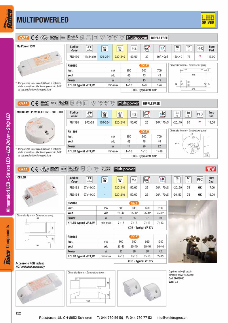
ROHScompliance
SELVCDT RIPPLE FREE
Mu Power 15W Codice
Code16A
Euro
Cad.
RN9150 115x34x19 176-264 220-240 50/60 30 10A 40μS -20..40 75 * 13,00
RN9150 CDT
Iout mA 350 500 700
Vout Vdc 43 43 43
Power W 15 15 15
N° LED typical VF 3,2V min-max 1÷12 1÷9 1÷6
COB - Typical VF 37V
RN1398 CDT
Iout mA 350 500 700
Vout Vdc 48 48 48
Power W 14 20 22
N° LED typical VF 3,2V min-max 1÷10 1÷10 1÷10
COB - Typical VF 37V
115
26
107
19
34
ROHScompliance
SELVCDT
24
72
Ø 10
RIPPLE FREE
MINIBRAVO POWERLED 350 - 500 - 700 Codice
Code16A
Euro
Cad.
RN1398 Ø72x24 176-264 220-240 50/60 25 20A 170μS -20..40 80 * 18,00
MULTIPOWERLED
ROHScompliance
SELVCDT
Codice
Code16A
Euro
Cad.
RN9163 97x44x30 - 220-240 50/60 25 20A 170μS -20..50 75 OK 17,00
RN9164 97x44x30 - 220-240 50/60 25 20A 170μS -20..50 75 OK 19,00
NEW
RN9163 CDT
Iout mA 500 600 650 700
Vout Vdc 25-42 25-42 25-42 25-42
Power W 21 25 27 30
N° LED typical VF 3,2V min-max 7÷13 7÷13 7÷13 7÷13
COB - Typical VF 37V
97
30
87
44
138
30
44
ICE LED
RN9164 CDT
Iout mA 800 900 950 1050
Vout Vdc 25-40 25-40 25-40 30-40
Power W 33 36 38 42
N° LED typical VF 3,2V min-max 7÷13 7÷13 7÷13 7÷13
COB - Typical VF 37V
Dimensioni (mm) - Dimensions (mm)
Dimensioni (mm) - Dimensions (mm)
* Per potenze inferiori a 24W non è richiesto
dalle normative - For lower powers to 24W
is not required by the regulations
* Per potenze inferiori a 24W non è richiesto
dalle normative - For lower powers to 24W
is not required by the regulations
DRIVER
Dimensioni (mm) - Dimensions (mm)
Dimensioni (mm) - Dimensions (mm)
Accessorio NON inclusoNOT included accessory
Coprimorsetto (2 pezzi)
Terminal cover (2 pieces)
Cod. 60408000
Euro: 0,3
Rütistrasse 18, CH-8952 Schlieren T: 044 730 56 56 F: 044 730 77 52 [email protected]
123
Ali
men
tato
ri L
ED
- S
tris
ce L
ED
- L
ED
Dri
ver
- S
trip
LE
DC
om
po
nen
ts
103
92
82
30
67
57
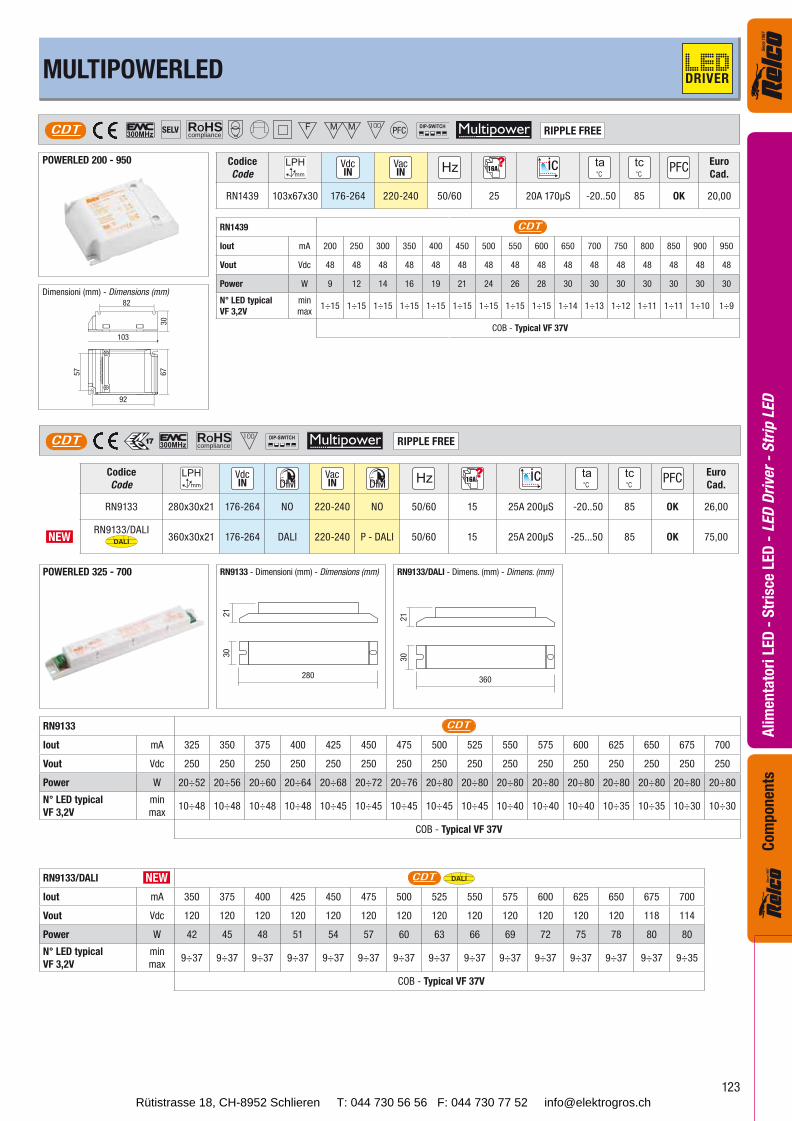
POWERLED 200 - 950
ROHScompliance
SELVCDT RIPPLE FREE
Codice
Code16A
Euro
Cad.
RN1439 103x67x30 176-264 220-240 50/60 25 20A 170μS -20..50 85 OK 20,00
PFC
RN1439 CDT
Iout mA 200 250 300 350 400 450 500 550 600 650 700 750 800 850 900 950
Vout Vdc 48 48 48 48 48 48 48 48 48 48 48 48 48 48 48 48
Power W 9 12 14 16 19 21 24 26 28 30 30 30 30 30 30 30
N° LED typical
VF 3,2V
min
max1÷15 1÷15 1÷15 1÷15 1÷15 1÷15 1÷15 1÷15 1÷15 1÷14 1÷13 1÷12 1÷11 1÷11 1÷10 1÷9
COB - Typical VF 37V
280
30
21
ROHScomplianceCDT RIPPLE FREE
POWERLED 325 - 700
Codice
Code16A
Euro
Cad.
RN9133 280x30x21 176-264 NO 220-240 NO 50/60 15 25A 200μS -20..50 85 OK 26,00
NEWRN9133/DALI
DALI 360x30x21 176-264 DALI 220-240 P - DALI 50/60 15 25A 200μS -25...50 85 OK 75,00
RN9133 CDT
Iout mA 325 350 375 400 425 450 475 500 525 550 575 600 625 650 675 700
Vout Vdc 250 250 250 250 250 250 250 250 250 250 250 250 250 250 250 250
Power W 20÷52 20÷56 20÷60 20÷64 20÷68 20÷72 20÷76 20÷80 20÷80 20÷80 20÷80 20÷80 20÷80 20÷80 20÷80 20÷80
N° LED typical
VF 3,2V
min
max10÷48 10÷48 10÷48 10÷48 10÷45 10÷45 10÷45 10÷45 10÷45 10÷40 10÷40 10÷40 10÷35 10÷35 10÷30 10÷30
COB - Typical VF 37V
MULTIPOWERLED
360
30
21
RN9133/DALI - Dimens. (mm) - Dimens. (mm)
RN9133/DALI CDT DALI
Iout mA 350 375 400 425 450 475 500 525 550 575 600 625 650 675 700
Vout Vdc 120 120 120 120 120 120 120 120 120 120 120 120 120 118 114
Power W 42 45 48 51 54 57 60 63 66 69 72 75 78 80 80
N° LED typical
VF 3,2V
min
max9÷37 9÷37 9÷37 9÷37 9÷37 9÷37 9÷37 9÷37 9÷37 9÷37 9÷37 9÷37 9÷37 9÷37 9÷35
COB - Typical VF 37V
NEW
Dimensioni (mm) - Dimensions (mm)
RN9133 - Dimensioni (mm) - Dimensions (mm)
DRIVER
Rütistrasse 18, CH-8952 Schlieren T: 044 730 56 56 F: 044 730 77 52 [email protected]
124
Ali
men
tato
ri L
ED
- S
tris
ce L
ED
- L
ED
Dri
ver
- S
trip
LE
DC
om
pon
ents
82
43
23
77
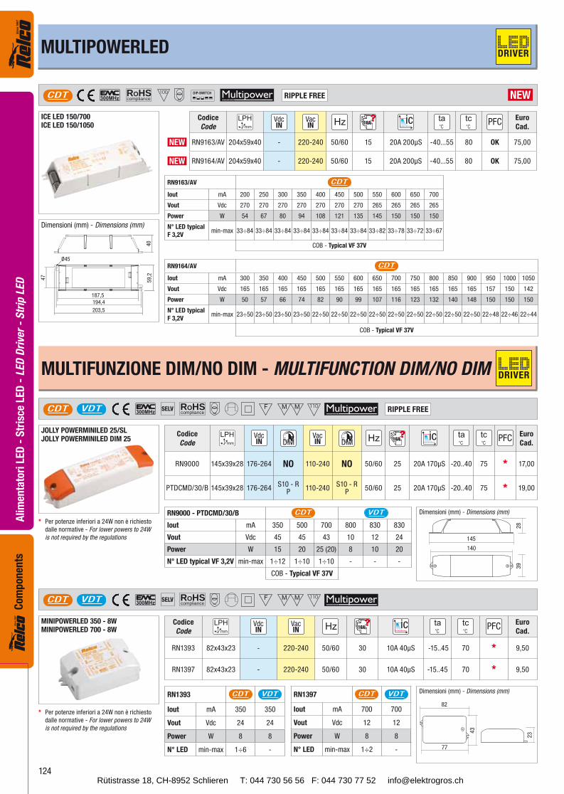
ROHScompliance
SELVCDT VDT
MINIPOWERLED 350 - 8WMINIPOWERLED 700 - 8W
Codice
Code16A
Euro
Cad.
RN1393 82x43x23 - 220-240 50/60 30 10A 40μS -15..45 70 * 9,50
RN1397 82x43x23 - 220-240 50/60 30 10A 40μS -15..45 70 * 9,50
RN1393 CDT VDT
Iout mA 350 350
Vout Vdc 24 24
Power W 8 8
N° LED min-max 1÷6 -
RN1397 CDT VDT
Iout mA 700 700
Vout Vdc 12 12
Power W 8 8
N° LED min-max 1÷2 -
ROHScompliance
SELVCDT VDT RIPPLE FREE
Codice
Code16A
Euro
Cad.
RN9000 145x39x28 176-264 NO 110-240 NO 50/60 25 20A 170μS -20..40 75 * 17,00
PTDCMD/30/B 145x39x28 176-264S10 - R
P110-240
S10 - RP
50/60 25 20A 170μS -20..40 75 * 19,00
RN9000 - PTDCMD/30/B CDT VDT
Iout mA 350 500 700 800 830 830
Vout Vdc 45 45 43 10 12 24
Power W 15 20 25 (20) 8 10 20
N° LED typical VF 3,2V min-max 1÷12 1÷10 1÷10 - - -
COB - Typical VF 37V
145
28
39
140
JOLLY POWERMINILED 25/SLJOLLY POWERMINILED DIM 25
MULTIPOWERLED DRIVER
ROHScomplianceCDT RIPPLE FREE
ICE LED 150/700ICE LED 150/1050
NEW
Codice
Code16A
Euro
Cad.
NEW RN9163/AV 204x59x40 - 220-240 50/60 15 20A 200μS -40...55 80 OK 75,00
NEW RN9164/AV 204x59x40 - 220-240 50/60 15 20A 200μS -40...55 80 OK 75,00
203,5
194,4
187,5
47
59
,24
0
Ø45
Dimensioni (mm) - Dimensions (mm)
RN9163/AV CDT
Iout mA 200 250 300 350 400 450 500 550 600 650 700
Vout Vdc 270 270 270 270 270 270 270 265 265 265 265
Power W 54 67 80 94 108 121 135 145 150 150 150
N° LED typical
F 3,2Vmin-max 33÷84 33÷84 33÷84 33÷84 33÷84 33÷84 33÷84 33÷82 33÷78 33÷72 33÷67
COB - Typical VF 37V
RN9164/AV CDT
Iout mA 300 350 400 450 500 550 600 650 700 750 800 850 900 950 1000 1050
Vout Vdc 165 165 165 165 165 165 165 165 165 165 165 165 165 157 150 142
Power W 50 57 66 74 82 90 99 107 116 123 132 140 148 150 150 150
N° LED typical
F 3,2Vmin-max 23÷50 23÷50 23÷50 23÷50 22÷50 22÷50 22÷50 22÷50 22÷50 22÷50 22÷50 22÷50 22÷50 22÷48 22÷46 22÷44
COB - Typical VF 37V
Dimensioni (mm) - Dimensions (mm)
* Per potenze inferiori a 24W non è richiesto
dalle normative - For lower powers to 24W
is not required by the regulations
Dimensioni (mm) - Dimensions (mm)
MULTIFUNZIONE DIM/NO DIM - MULTIFUNCTION DIM/NO DIM
* Per potenze inferiori a 24W non è richiesto
dalle normative - For lower powers to 24W
is not required by the regulations
DRIVER
Rütistrasse 18, CH-8952 Schlieren T: 044 730 56 56 F: 044 730 77 52 [email protected]
125
Ali
men
tato
ri L
ED
- S
tris
ce L
ED
- L
ED
Dri
ver
- S
trip
LE
DC
om
po
nen
ts
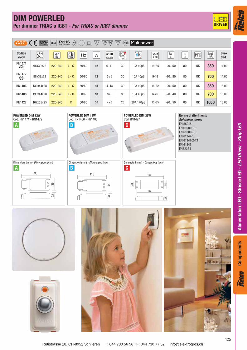
Codice
Coden°LEDmin-max
16A VoutVdc
IoutmA
Euro
Cad.
RN147198x39x22 220-240 L - C 50/60 12 6÷11 30 10A 40μS 18-35 -20...50 80 OK 350 14,00
RN147298x39x22 220-240 L - C 50/60 12 3÷6 30 10A 40μS 9-18 -20...50 80 OK 700 14,00
RN1406 133x44x28 220-240 L - C 50/60 18 4÷13 30 10A 40μS 15-52 -20...50 80 OK 350 18,00
RN1408 133x44x28 220-240 L - C 50/60 18 3÷5 30 10A 40μS 6-26 -20...40 80 OK 700 18,00
RN1427 167x55x25 220-240 C 50/60 36 4÷8 25 20A 170μS 15-35 -20...50 80 OK 1050 18,00
ROHScompliance
SELVCDT PFC
POWERLED DIM 12WCod. RN1471 - RN1472
A
166
52
24
160
43
POWERLED DIM 18WCod. RN1406 - RN1408
B
POWERLED DIM 36WCod. RN1427
C
98
39
22
113
44
28
A B C
Dimensioni (mm) - Dimensions (mm) Dimensioni (mm) - Dimensions (mm) Dimensioni (mm) - Dimensions (mm)
DIM POWERLEDPer dimmer TRIAC o IGBT - For TRIAC or IGBT dimmer
Norme di riferimento
Reference norms
EN 55015
EN 61000-3-2
EN 61000-3-3
EN 61347-1
EN 61347-2-13
EN 61547
EN62384
DRIVER
Rütistrasse 18, CH-8952 Schlieren T: 044 730 56 56 F: 044 730 77 52 [email protected]
126
Ali
men
tato
ri L
ED
- S
tris
ce L
ED
- L
ED
Dri
ver
- S
trip
LE
DC
om
pon
ents
ROHScompliance
SELVCDT
Articolo
Article
Codice
Coden°LEDmin-max
16A VoutVdc
IoutmA
Euro
Cad.
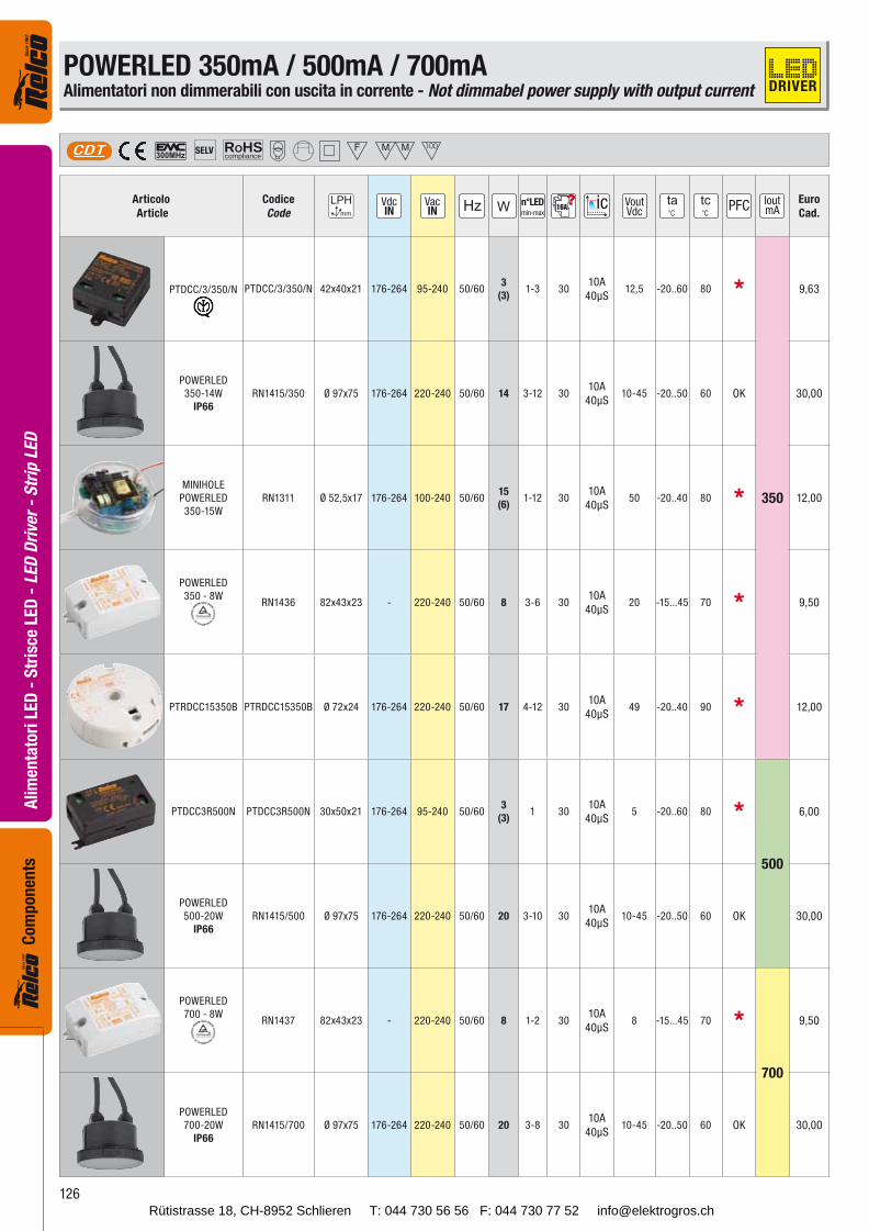
PTDCC/3/350/N PTDCC/3/350/N 42x40x21 176-264 95-240 50/603
(3)1-3 30
10A
40μS12,5 -20..60 80 *
350
9,63
POWERLED
350-14W
IP66
RN1415/350 Ø 97x75 176-264 220-240 50/60 14 3-12 3010A
40μS10-45 -20..50 60 OK 30,00
MINIHOLE
POWERLED
350-15W
RN1311 Ø 52,5x17 176-264 100-240 50/6015
(6)1-12 30
10A
40μS50 -20..40 80 * 12,00
POWERLED
350 - 8WRN1436 82x43x23 - 220-240 50/60 8 3-6 30
10A
40μS20 -15...45 70 * 9,50
PTRDCC15350B PTRDCC15350B Ø 72x24 176-264 220-240 50/60 17 4-12 3010A
40μS49 -20..40 90 * 12,00
PTDCC3R500N PTDCC3R500N 30x50x21 176-264 95-240 50/603
(3)1 30
10A
40μS5 -20..60 80 *
500
6,00
POWERLED
500-20W
IP66
RN1415/500 Ø 97x75 176-264 220-240 50/60 20 3-10 3010A
40μS10-45 -20..50 60 OK 30,00
POWERLED
700 - 8WRN1437 82x43x23 - 220-240 50/60 8 1-2 30
10A
40μS8 -15...45 70 *
700
9,50
POWERLED
700-20W
IP66
RN1415/700 Ø 97x75 176-264 220-240 50/60 20 3-8 3010A
40μS10-45 -20..50 60 OK 30,00
POWERLED 350mA / 500mA / 700mAAlimentatori non dimmerabili con uscita in corrente - Not dimmabel power supply with output current DRIVER
Rütistrasse 18, CH-8952 Schlieren T: 044 730 56 56 F: 044 730 77 52 [email protected]
127
Ali
men
tato
ri L
ED
- S
tris
ce L
ED
- L
ED
Dri
ver
- S
trip
LE
DC
om
po
nen
ts
ROHScompliance
SELVVDT
Articolo
Article
Codice
Code16A Vout
VdcEuro
Cad.
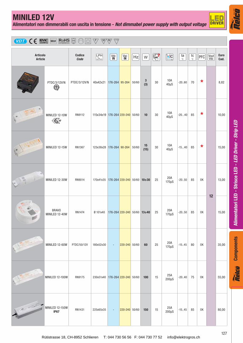
PTDC/3/12V/N PTDC/3/12V/N 40x42x21 176-264 95-264 50/603
(3)30
10A
40μS-20..60 70 *
12
8,82
MINILED 12-10W RN9112 115x34x19 176-264 220-240 50/60 10 3010A
40μS-20...40 85 * 10,00
MINILED 12-15W RN1367 123x38x28 176-264 90-264 50/6015
(15)30
10A
40μS-15...40 85 * 15,00
MINILED 12-30W RN9014 170x41x35 176-264 220-240 50/60 10÷30 2520A
170μS-20..50 85 OK 13,00
BRAVO
MINILED 12-40WRN1474 Ø 101x40 176-264 220-240 50/60 13÷40 25
20A
170μS-20..50 85 OK 15,00
MINILED 12-60W PTDC/50/12V 180x52x30 - 220-240 50/60 60 2520A
170μS-15..45 80 OK 35,00
MINILED 12-100W RN9175 230x51x40 176-264 220-240 50/60 100 1525A
200μS-20..40 75 OK 55,00
MINILED 12-150W
IP67RN1431 225x65x35 - 220-240 50/60 150 15
25A
200μS-15..45 85 OK 80,00
MINILED 12VAlimentatori non dimmerabili con uscita in tensione - Not dimmabel power supply with output voltage DRIVER
Rütistrasse 18, CH-8952 Schlieren T: 044 730 56 56 F: 044 730 77 52 [email protected]
128
Ali
men
tato
ri L
ED
- S
tris
ce L
ED
- L
ED
Dri
ver
- S
trip
LE
DC
om
pon
ents
ROHScompliance
SELVVDT
Articolo
Article
Codice
Code16A Vout
VdcEuro
Cad.
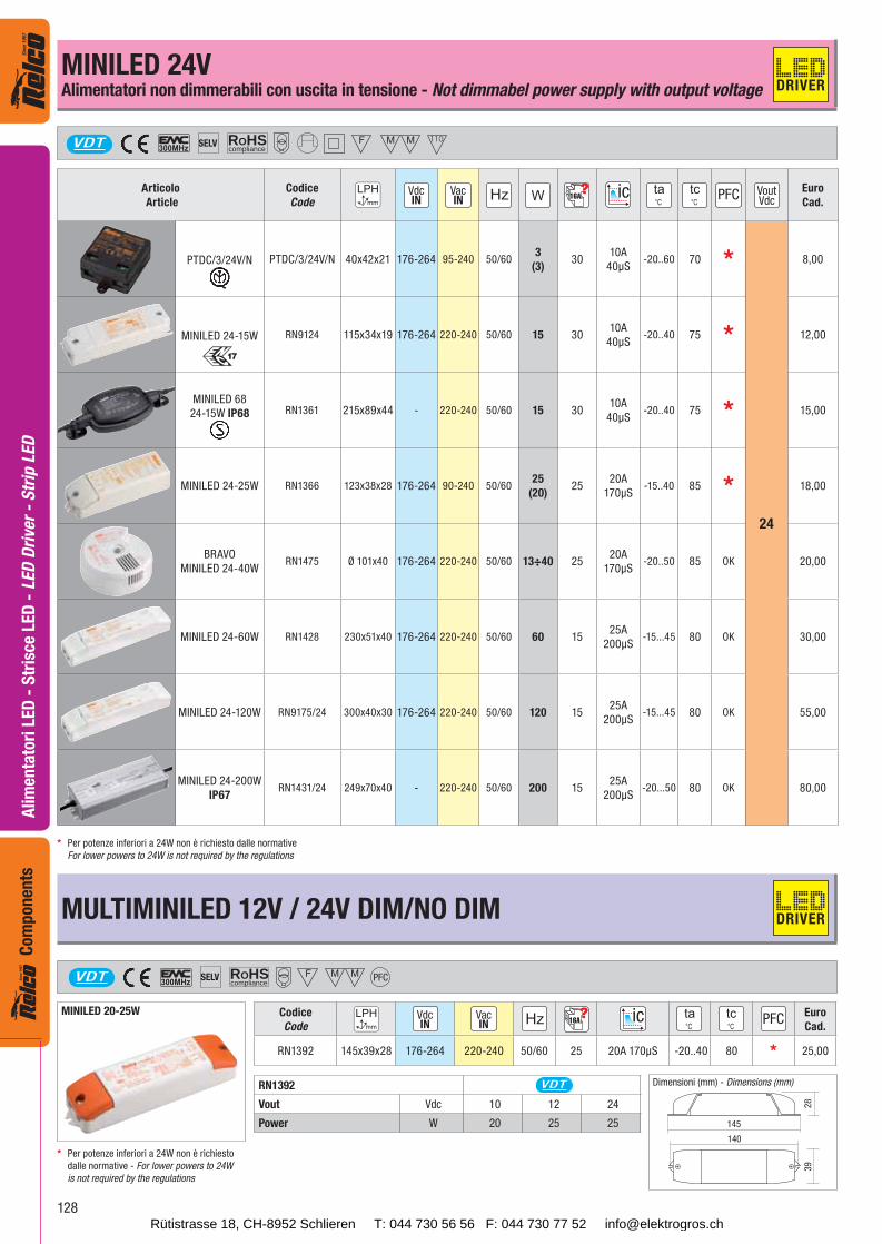
PTDC/3/24V/N PTDC/3/24V/N 40x42x21 176-264 95-240 50/603
(3)30
10A
40μS-20..60 70 *
24
8,00
MINILED 24-15W RN9124 115x34x19 176-264 220-240 50/60 15 3010A
40μS-20..40 75 * 12,00
MINILED 68
24-15W IP68 RN1361 215x89x44 - 220-240 50/60 15 3010A
40μS-20..40 75 * 15,00
MINILED 24-25W RN1366 123x38x28 176-264 90-240 50/6025
(20)25
20A
170μS-15..40 85 * 18,00
BRAVO
MINILED 24-40WRN1475 Ø 101x40 176-264 220-240 50/60 13÷40 25
20A
170μS-20..50 85 OK 20,00
MINILED 24-60W RN1428 230x51x40 176-264 220-240 50/60 60 1525A
200μS-15...45 80 OK 30,00
MINILED 24-120W RN9175/24 300x40x30 176-264 220-240 50/60 120 1525A
200μS-15...45 80 OK 55,00
MINILED 24-200W
IP67RN1431/24 249x70x40 - 220-240 50/60 200 15
25A
200μS-20...50 80 OK 80,00
MULTIMINILED 12V / 24V DIM/NO DIM
ROHScompliance
SELVVDT PFC
MINILED 20-25W Codice
Code16A
Euro
Cad.
RN1392 145x39x28 176-264 220-240 50/60 25 20A 170μS -20..40 80 * 25,00
145
28
39
140
RN1392 VDT
Vout Vdc 10 12 24
Power W 20 25 25
MINILED 24VAlimentatori non dimmerabili con uscita in tensione - Not dimmabel power supply with output voltage
Dimensioni (mm) - Dimensions (mm)
* Per potenze inferiori a 24W non è richiesto
dalle normative - For lower powers to 24W
is not required by the regulations
* Per potenze inferiori a 24W non è richiesto dalle normative
For lower powers to 24W is not required by the regulations
DRIVER
DRIVER
Rütistrasse 18, CH-8952 Schlieren T: 044 730 56 56 F: 044 730 77 52 [email protected]
129
Ali
men
tato
ri L
ED
- S
tris
ce L
ED
- L
ED
Dri
ver
- S
trip
LE
DC
om
po
nen
ts
230
40
51
225
230
40
51
225
ROHScompliance
SELVVDT PFC
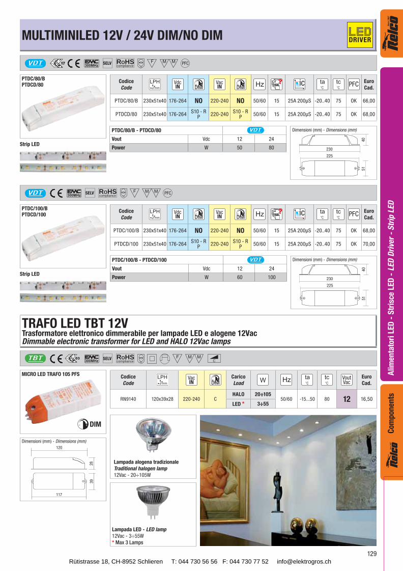
PTDC/80/BPTDCD/80
Codice
Code16A
Euro
Cad.
PTDC/80/B 230x51x40 176-264 NO 220-240 NO 50/60 15 25A 200μS -20..40 75 OK 66,00
PTDCD/80 230x51x40 176-264S10 - R
P220-240
S10 - RP
50/60 15 25A 200μS -20..40 75 OK 68,00
PTDC/80/B - PTDCD/80 VDT
Vout Vdc 12 24
Power W 50 80
PTDC/100/B - PTDCD/100 VDT
Vout Vdc 12 24
Power W 60 100
ROHScompliance
SELVVDT PFC
PTDC/100/BPTDCD/100
Codice
Code16A
Euro
Cad.
PTDC/100/B 230x51x40 176-264 NO 220-240 NO 50/60 15 25A 200μS -20..40 75 OK 68,00
PTDCD/100 230x51x40 176-264S10 - R
P220-240
S10 - RP
50/60 15 25A 200μS -20..40 75 OK 70,00
ROHScompliance
SELV C
MICRO LED TRAFO 105 PFS
DIM
TRAFO LED TBT 12VTrasformatore elettronico dimmerabile per lampade LED e alogene 12VacDimmable electronic transformer for LED and HALO 12Vac lamps
TBT
Codice
Code
Carico
LoadVoutVac
Euro
Cad.
RN9140 120x39x28 220-240 CHALO 20÷105
50/60 -15...50 80 12 16,50LED * 3÷55
120
39
28
117
Lampada LED - LED lamp
12Vac - 3÷55W
* Max 3 Lamps
Strip LED
Strip LED
Dimensioni (mm) - Dimensions (mm)
Dimensioni (mm) - Dimensions (mm)
Dimensioni (mm) - Dimensions (mm)
Lampada alogena tradizionale
Traditional halogen lamp
12Vac - 20÷105W
MULTIMINILED 12V / 24V DIM/NO DIM DRIVER
Rütistrasse 18, CH-8952 Schlieren T: 044 730 56 56 F: 044 730 77 52 [email protected]
130
Ali
men
tato
ri L
ED
- S
tris
ce L
ED
- L
ED
Dri
ver
- S
trip
LE
DC
om
pon
ents
ROHScompliance
SELV PFC
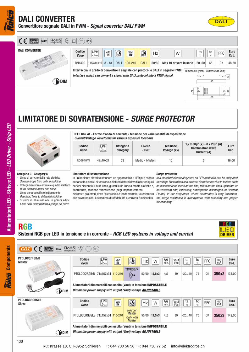
DALI CONVERTER
DIM
Codice
Code
Euro
Cad.
RN1300 115x34x19 8 - 13 DALI 100-240 DALI 50/60 Max 10 drivers in serie -20..50 65 OK 48,50
115
21
103
19
34
IEEE C62.41 - Forme d’onda di corrente / tensione per varie località di esposizione
Current/Voltage waveforms for various exposure locations
Codice
Code
Categoria
Category
Livello
Level
Tensione
Voltage (kV)
1,2 x 50μS (V) - 8 x 20μS (A)
Combination wave
Current (A)
Euro
Cad.
RO0640/N 42x40x21 C2 Medio - Medium 10 5 16,00
ROHScompliance
SELVCDT PFC
PTDLDCC/RGB/BMaster
Codice
CodeVoutVdc
IoutmA
Euro
Cad.
PTDLDCC/RGB/B 71x157x34 110-240
TC/RGB/N
50/60 12,5x3 4x3 39 -20...40 75 OK 350x3 134,00
PTDLDCCRGBSLBSlave
Codice
CodeVoutVdc
IoutmA
Euro
Cad.
PTDLDCCRGBSLB 71x157x34 110-240
Solo con Master
Only withMaster
50/60 12,5x3 4x3 39 -20...40 75 OK 350x3 142,00
DIM
DIM
DALIDALI CONVERTERConvertitore segnale DALI in PWM - Signal converter DALI PWM
Dimensioni (mm) - Dimensions (mm)Interfaccia in grado di convertire il segnale con protocollo DALI in segnale PWM
Interface which can convert a signal with DALI protocol into a PMW signal
Categoria C - Category C
- Linea di servizio dalla rete elettrica
Service drops from pole to building
- Collegamento tra centrale e quadro elettrico
Runs between meter and panel
- Linee aeree a edificio indipendente
Overhead lines to detached building
- Sistemi di illuminazione in grandi edifici
Linee della metropolitana a pompa nel pozzo
Limitatore di sovratensione
In un impianto elettrico standard un apparecchio a LED può essere
sottoposto a sbalzi di tensione e disturbi esterni dovuti a fattori quali
carichi discontinui sulla linea, guasti sulle linee a monte o a valle e,
soprattutto, scariche atmosferiche (negli impanti esterni).
Nei nostri proiettori, dove l’elettronica è fondamentale, la resistenza
alle sovratensioni è sinonimo di affidabilità e corretta funzionalità.
Surge protector
In a standard electrical system an LED luminaire can be subjected
to voltage fluctuations and external disturbances due to factors such
as discontinuous loads on the line, faults on the lines upstream or
downstream and, especially, atmospheric discharges (in External
Plants). In our projectors, where electronics is very important,
the surge resistance is synonymous with reliability and proper
functionality.
LIMITATORE DI SOVRATENSIONE - SURGE PROTECTOR
RGBSistemi RGB per LED in tensione e in corrente - RGB LED systems in voltage and current
Alimentatori dimmerabili con uscita (Vout) in tensione IMPOSTABILE
Dimmable power supply with output (Vout) voltage ADJUSTABLE
Alimentatori dimmerabili con uscita (Vout) in tensione IMPOSTABILE
Dimmable power supply with output (Vout) voltage ADJUSTABLE
DRIVER
RGB
Rütistrasse 18, CH-8952 Schlieren T: 044 730 56 56 F: 044 730 77 52 [email protected]
131
Ali
men
tato
ri L
ED
- S
tris
ce L
ED
- L
ED
Dri
ver
- S
trip
LE
DC
om
pon
ents
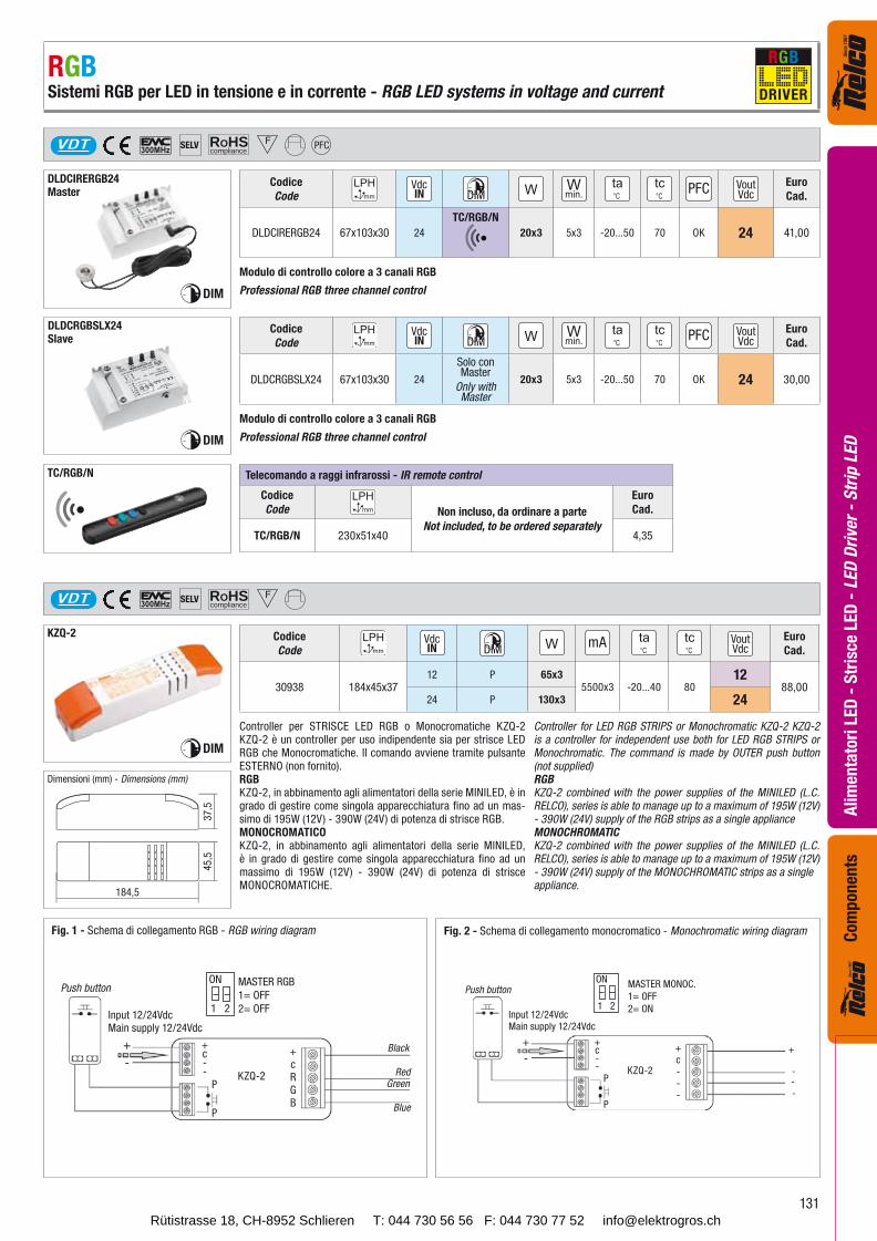
TC/RGB/N Telecomando a raggi infrarossi - IR remote control
Codice
Code Non incluso, da ordinare a parte
Not included, to be ordered separately
Euro
Cad.
TC/RGB/N 230x51x40 4,35
ROHScompliance
SELV PFC
DLDCIRERGB24Master
Codice
CodeVoutVdc
Euro
Cad.
DLDCIRERGB24 67x103x30 24
TC/RGB/N
20x3 5x3 -20...50 70 OK 24 41,00
DLDCRGBSLX24Slave
Codice
CodeVoutVdc
Euro
Cad.
DLDCRGBSLX24 67x103x30 24
Solo con Master
Only withMaster
20x3 5x3 -20...50 70 OK 24 30,00
DIM
DIM
184,5
45,5
37,5
ROHScompliance
SELVVDT
KZQ-2
DIM
Codice
CodemA Vout
VdcEuro
Cad.
30938 184x45x3712 P 65x3
5500x3 -20...40 8012
88,0024 P 130x3 24
Push button
+
-
Input 12/24VdcMain supply 12/24Vdc
+c--
P
P
KZQ-2
+c---
+
---
MASTER MONOC.
1= OFF
2= ON
Fig. 1 - Schema di collegamento RGB - RGB wiring diagram Fig. 2 - Schema di collegamento monocromatico - Monochromatic wiring diagram
Push button
+
-
Input 12/24VdcMain supply 12/24Vdc
+c--
P
P
KZQ-2
+cRGB
Black
RedGreen
Blue
MASTER RGB
1= OFF
2= OFF
ON
1 2
ON
1 2
VDT
Modulo di controllo colore a 3 canali RGB
Professional RGB three channel control
Modulo di controllo colore a 3 canali RGB
Professional RGB three channel control
Dimensioni (mm) - Dimensions (mm)
Controller per STRISCE LED RGB o Monocromatiche KZQ-2 KZQ-2 è un controller per uso indipendente sia per strisce LED RGB che Monocromatiche. Il comando avviene tramite pulsante ESTERNO (non fornito).RGBKZQ-2, in abbinamento agli alimentatori della serie MINILED, è in grado di gestire come singola apparecchiatura fino ad un mas-simo di 195W (12V) - 390W (24V) di potenza di strisce RGB.MONOCROMATICOKZQ-2, in abbinamento agli alimentatori della serie MINILED, è in grado di gestire come singola apparecchiatura fino ad un massimo di 195W (12V) - 390W (24V) di potenza di strisce MONOCROMATICHE.
Controller for LED RGB STRIPS or Monochromatic KZQ-2 KZQ-2 is a controller for independent use both for LED RGB STRIPS or Monochromatic. The command is made by OUTER push button (not supplied)RGBKZQ-2 combined with the power supplies of the MINILED (L.C. RELCO), series is able to manage up to a maximum of 195W (12V) - 390W (24V) supply of the RGB strips as a single applianceMONOCHROMATICKZQ-2 combined with the power supplies of the MINILED (L.C. RELCO), series is able to manage up to a maximum of 195W (12V) - 390W (24V) supply of the MONOCHROMATIC strips as a singleappliance.
RGBSistemi RGB per LED in tensione e in corrente - RGB LED systems in voltage and current DRIVER
RGB
Rütistrasse 18, CH-8952 Schlieren T: 044 730 56 56 F: 044 730 77 52 [email protected]
132
Ali
men
tato
ri L
ED
- S
tris
ce L
ED
- L
ED
Dri
ver
- S
trip
LE
DC
om
pon
ents
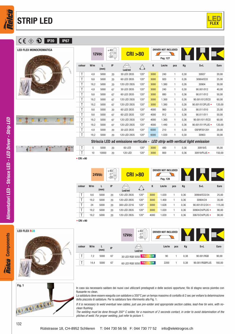
12Vdc CRI >80+40
-20
DRIVER NOT INCLUDED
Pag. 127
IP67IP20
colour W/m L
(mm)
IP K Lm/m pcs Kg S+L Euro
Led/mt
T 4,8 5000 20 30 LED 2835 120° 3000 240 1 0,30 30937 20,00
T 9,6 5000 20 60 LED 2835 120° 3000 920 1 0,26 30904/ECO 25,00
T 19,2 5000 20 120 LED 2835 120° 3000 1.380 1 0,26 30904 30,00
T 4,8 5000 67 30 LED 2835 120° 3000 240 1 0,30 90.001/012 40,00
T 9,6 5000 67 60 LED 2835 120° 3000 880 1 0,36 90.011/012 50,00
T 19,2 5000 67 120 LED 2835 120° 3000 1.300 1 0,26 90.001/012/ECO 60,00
T 19,2 5000 67 120 LED 2835 120° 3000 1.380 1 0,26 90.001/012PLUS 120,00
T 9,6 5000 20 60 LED 2835 120° 4000 960 1 0,26 90.011/010 25,00
T 9,6 5000 67 60 LED 2835 120° 4000 912 1 0,36 90.011/011 50,00
T 19,2 5000 67 120 LED 2835 120° 4000 1.360 1 0,36 90.001/011/ECO 60,00
T 19,2 5000 67 120 LED 2835 120° 4000 1.440 1 0,36 90.001/011PLUS 120,00
T 4,8 5000 20 30 LED 2835 120° 6000 210 1 0,30 OSF8P201201 20,00
T 19,2 5000 20 120 LED 2835 120° 6000 1.020 1 0,30 30903 30,00
Striscia LED ad emissione verticale - LED strip with vertical light emission
T 5 5000 20 60 LED 120° 3000 480 1 0,36 30919/S 95,00
T 10 10000 20 120 LED 120° 3000 800 1 0,36 30919/PLUS 150,00
CRI >90
LED FLEX MONOCROMATICA
24Vdc CRI >80+40
-20
DRIVER NOT INCLUDED
Pag. 128
colour W/m L
(mm)
IP K Lm/m pcs Kg S+L Euro
Led/mt
T 9,6 5000 20 120 LED 2835 120° 3000 1.020 1 0,36 30904/ECO/24 25,00
T 19,2 5000 20 120 LED 2835 120° 3000 1.400 1 0,36 30904/24 35,00
T 24 5000 20 300 LED 2216 120° 3000 1.628 1 0,36 90.001/012/24 115,00
T 19,2 5000 20 120 LED 2835 120° 3000 1.020 1 0,36 30904/24/PLUS 90,00
T 19,2 5000 20 120 LED 2835 120° 4000 1.020 1 0,36 30670/24/PLUS 90,00
CRI >90
+40
-2012Vdc
DRIVER NOT INCLUDED
colour W/m L
(mm)IP
Lm/m pcs Kg S+L Euro
Led/mt
T 7,2 5000 67 30 LED RGB 5050 FULLCOLOR 90 1 0,38 90.001/RGB 90,00
T 14,4 5000 67 60 LED RGB 5050 FULLCOLOR 2200 1 0,38 90.001/RGBPLUS 160,00
Fig. 1In caso sia necessario saldare dei nuovi cavi utilizzarli prestagnati e delle sezioni opportune; filo di stagno senza piombo con
flussante no clean.
La saldatura deve essere eseguita con saldatore a 350°C per un tempo massimo di contatto di 2 sec per evitare la delaminazione
della piazzola di saldature. Per la saldatura fare riferimento alla Fig. 1.
If it is necessary to weld eventual new cables, just use pre-solder and appropriate section cables, lead-free tin wire, with no-
clean flushing.
The welding must be done through 350° C solder, for a maximum of 2 seconds contact, in order to avoid delamination of the
pitches of weld. For proper welding, just refer to picture 1.
LED FLEX RGB
STRIP LED FLEX
Rütistrasse 18, CH-8952 Schlieren T: 044 730 56 56 F: 044 730 77 52 [email protected]