Embed Size (px)
Citation preview
ulics
aulik Hydra
k Hydraulics Hyd
draulique Hydraulik
Hy
raulik Hydraulics
Hydrauliqu
Hydraulique Hydraulik
Hydraulics
Hydraulik Hydraulics
Hydraulique
aulique Hydraulik
Hydraulics Hyd
Hydraulique Hydraulik
Hydraulics
cs Hydraulique Hydraulik
Hydra
Hydraulics Hydraulique
Hydraulik
ulik Hydraulics
Hydraulique Hyd
Hydraulik Hydraulics
Hydraulique
aulique Hydraulik
Hydraulics
draulique Hydraulik
Hydr
draulik Hydraulics
lique Hydra
lics H
HyHK.51.A3.02Book 8 Partition 2
Catalogue
Load-independentProportional ValveType PVG 120With mechanical actuationWith electrical remote control and mechanical actuationWith hydraulic remote control and mechanical actuation
2
Contents
HK.51.A-
Side
General 3
Function 4
Hydraulic systems 6
Technical data 7
Electrical actuation 9
Modules and Pump side modules, PVP 11code numbers Accessory modules for PVP 11
Basic modules, PVB 12Accessory modules for PVB 12Shock and suction valve, PVLP 13Suction valve, PVLA 13 Main spools, PVBS 13Mechanical actuation, PVM 13Cover for mechanically or hydrauliclyoperated valve, PVMD, PVH 13Electrical actuation, PVEH and PVEO 14Tank side module, PVT 14Assembly kit, PVAS 14Modules for oil flow exceeding 180 l/min 14
Technical characteristics 15
Dimensions 17
System safety 19
Other operating conditions and conversion factors 22
Order specification 23
Module selection chart 24
Contents
INTERNATIONAL STANDARDINTERNATIONAL ORGANIZATION FOR STANDARDIZATION
ORGANISATION INTERNATIONALE DE NORMALISATION
Quality management and quality assurance standards
ISO9001
Danfoss Mobile Hydraulics have been manufactured to meet the Quality demands specified by ISO 9001.
ISO 9001
3
General
HK.51.A-
• Electrical control unit PVRES, 155B.... • Hydraulic control unit PVRH, 155B....
• Electrical control unit PVREL, 155U....
• Closed loop speed control - EHSC• Alarm logic - EHA• Closed loop position control - EHC
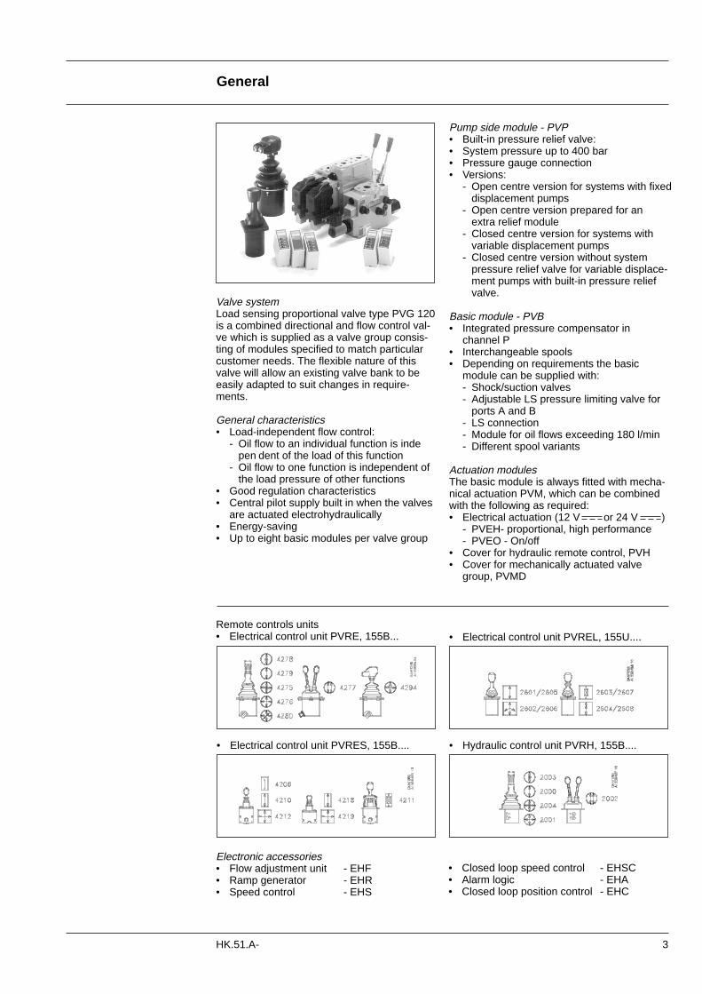
Valve systemLoad sensing proportional valve type PVG 120is a combined directional and flow control val-ve which is supplied as a valve group consis-ting of modules specified to match particularcustomer needs. The flexible nature of thisvalve will allow an existing valve bank to beeasily adapted to suit changes in require-ments.
General characteristics• Load-independent flow control:
- Oil flow to an individual function is indepen dent of the load of this function
- Oil flow to one function is independent of the load pressure of other functions
• Good regulation characteristics• Central pilot supply built in when the valves
are actuated electrohydraulically• Energy-saving• Up to eight basic modules per valve group
Pump side module - PVP• Built-in pressure relief valve:• System pressure up to 400 bar• Pressure gauge connection• Versions:
- Open centre version for systems with fixed displacement pumps
- Open centre version prepared for an extra relief module
- Closed centre version for systems with variable displacement pumps
- Closed centre version without system pressure relief valve for variable displace-ment pumps with built-in pressure relief valve.
Basic module - PVB• Integrated pressure compensator in
channel P• Interchangeable spools• Depending on requirements the basic
module can be supplied with:- Shock/suction valves- Adjustable LS pressure limiting valve for
ports A and B- LS connection- Module for oil flows exceeding 180 l/min- Different spool variants
Actuation modulesThe basic module is always fitted with mecha-nical actuation PVM, which can be combinedwith the following as required:• Electrical actuation (12 V or 24 V )
- PVEH- proportional, high performance- PVEO - On/off
• Cover for hydraulic remote control, PVH• Cover for mechanically actuated valve
group, PVMD
Remote controls units• Electrical control unit PVRE, 155B...
Electronic accessories• Flow adjustment unit - EHF• Ramp generator - EHR• Speed control - EHS
4 HK.51.A-
Function
In the basic module the compensator (5)maintains a constant pressure drop across themain spool - both when the load changes andwhen a module with a higher load pressure isactivated.
Shock and suction valves with a fixed setting(7) and the suction valves (8) on ports A and Bare used to protect individual working func-tions against overload.
In the basic module it is possible to build in anadjustable LS pressure relief valve (6) to limitthe pressure from each working function. The LS pressure limiting valve saves energy:- Without LS pressure limiting valve all the oil
flow to the working function will be led across the combined shock and suction valves to tank if the pressure exceeds the fixed setting of the valves.
- With LS pressure limiting valve an oil flow of only about 2 l/min will be led across the LS pressure limiting valve to tank if the pressure exceeds the valve setting.
Open PVG 120 with opencentre PVP
Open PVG 120 with closedcentre PVP
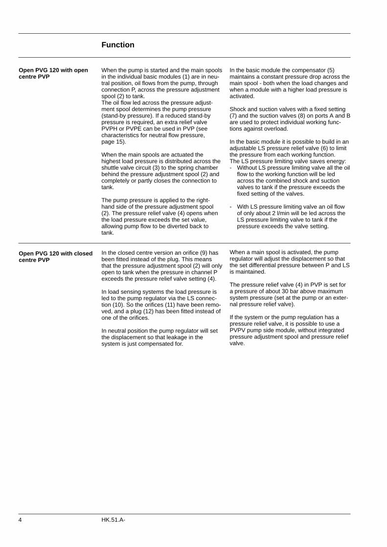
When the pump is started and the main spoolsin the individual basic modules (1) are in neu-tral position, oil flows from the pump, throughconnection P, across the pressure adjustmentspool (2) to tank.The oil flow led across the pressure adjust-ment spool determines the pump pressure(stand-by pressure). If a reduced stand-bypressure is required, an extra relief valvePVPH or PVPE can be used in PVP (seecharacteristics for neutral flow pressure, page 15).
When the main spools are actuated the highest load pressure is distributed across theshuttle valve circuit (3) to the spring chamberbehind the pressure adjustment spool (2) andcompletely or partly closes the connection totank.
The pump pressure is applied to the right-hand side of the pressure adjustment spool(2). The pressure relief valve (4) opens whenthe load pressure exceeds the set value,allowing pump flow to be diverted back totank.
In the closed centre version an orifice (9) hasbeen fitted instead of the plug. This meansthat the pressure adjustment spool (2) will onlyopen to tank when the pressure in channel Pexceeds the pressure relief valve setting (4).
In load sensing systems the load pressure isled to the pump regulator via the LS connec-tion (10). So the orifices (11) have been remo-ved, and a plug (12) has been fitted instead ofone of the orifices.
In neutral position the pump regulator will setthe displacement so that leakage in thesystem is just compensated for.
When a main spool is activated, the pumpregulator will adjust the displacement so thatthe set differential pressure between P and LSis maintained.
The pressure relief valve (4) in PVP is set fora pressure of about 30 bar above maximumsystem pressure (set at the pump or an exter-nal pressure relief valve).
If the system or the pump regulation has apressure relief valve, it is possible to use aPVPV pump side module, without integratedpressure adjustment spool and pressure reliefvalve.
Function
5HK.51.A-
PVG 120 sectionaldrawing
1. Main spool2. Pressure adjustment
spool in PVP3. Shuttle valve4. Pressure relief valve in PVP5. Pressure compensator in PVB6. LS pressure relief valve in PVB7. Shock and suction valve PVLP8. Suction valve PVLA9. Orifice, closed centre PVP
Plug, open centre PVP10.LS connection11. Orifice, open centre PVP12.Plug, closed centre PVP
6
Hydraulic systems
HK.51.A-
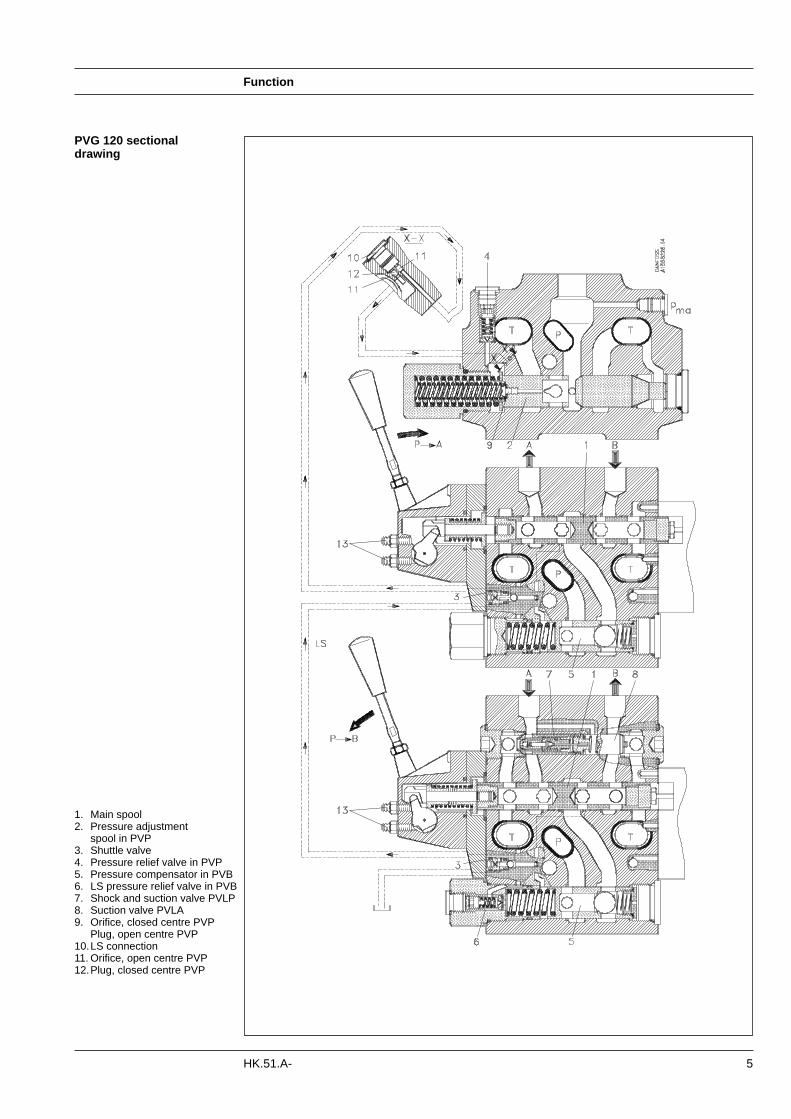
PVG 120 with variable displacement pump
Examples PVG 120 with fixed displacement pump
7
Technical data
HK.51.A-
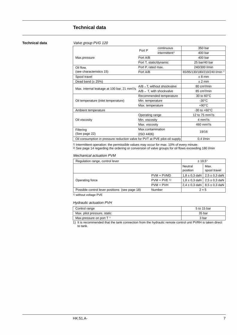
Regulation range, control lever ± 19,5°
Neutral Max.position spool travel
PVM + PVMD 1,8 ± 0,3 daN 2,5 ± 0,3 daN
Operating force PVM + PVE 1) 1,8 ± 0,3 daN 2,5 ± 0,3 daN
PVM + PVH 2,4 ± 0,3 daN 8,5 ± 0,3 daN
Possible control lever positions (see page 18) Number 2 × 5
Technical data
Port Pcontinuous 350 bar
intermittent1) 400 bar
Max.pressure Port A/B 400 bar
Port T, static/dynamic 25 bar/40 bar
Oil flow, Port P, rated max. 240/300 l/min(see characteristics 15) Port A/B 65/95/130/180/210/240 l/min 2)
Spool travel ± 8 mm
Dead band (± 25%) ± 2 mm
Max. internal leakage at 100 bar, 21 mm2/sA/B→T, without shockvalve 80 cm3/min
A/B→ T, with shockvalve 85 cm3/min
Recommended temperature 30 to 60°C
Oil temperature (inlet temperature) Min. temperature -30°C
Max. temperature +90°C
Ambient temperature -30 to +60°C
Operating range 12 to 75 mm2/s
Oil viscosity Min. viscosity 4 mm2/s
Max. viscosity 460 mm2/s
Filtering Max.contamination 19/16
(See page 22) (ISO 4406)
Oil consumption in pressure reduction valve for PVT at PVE pilot-oil supply 0,4 l/min
Valve group PVG 120
Control range 5 to 15 bar
Max. pilot pressure, static 35 bar
Max.pressure on port T 1) 3 bar
Mechanical actuation PVM
Hydraulic actuation PVH
1) Intermittent operation: the permissible values may occur for max. 10% of every minute.2) See page 14 regarding the ordering or conversion of valve groups for oil flows exceeding 180 l/min
1) without voltage PVE
1) It is recommended that the tank connection from the hydraulic remote control unit PVRH is taken direct to tank.
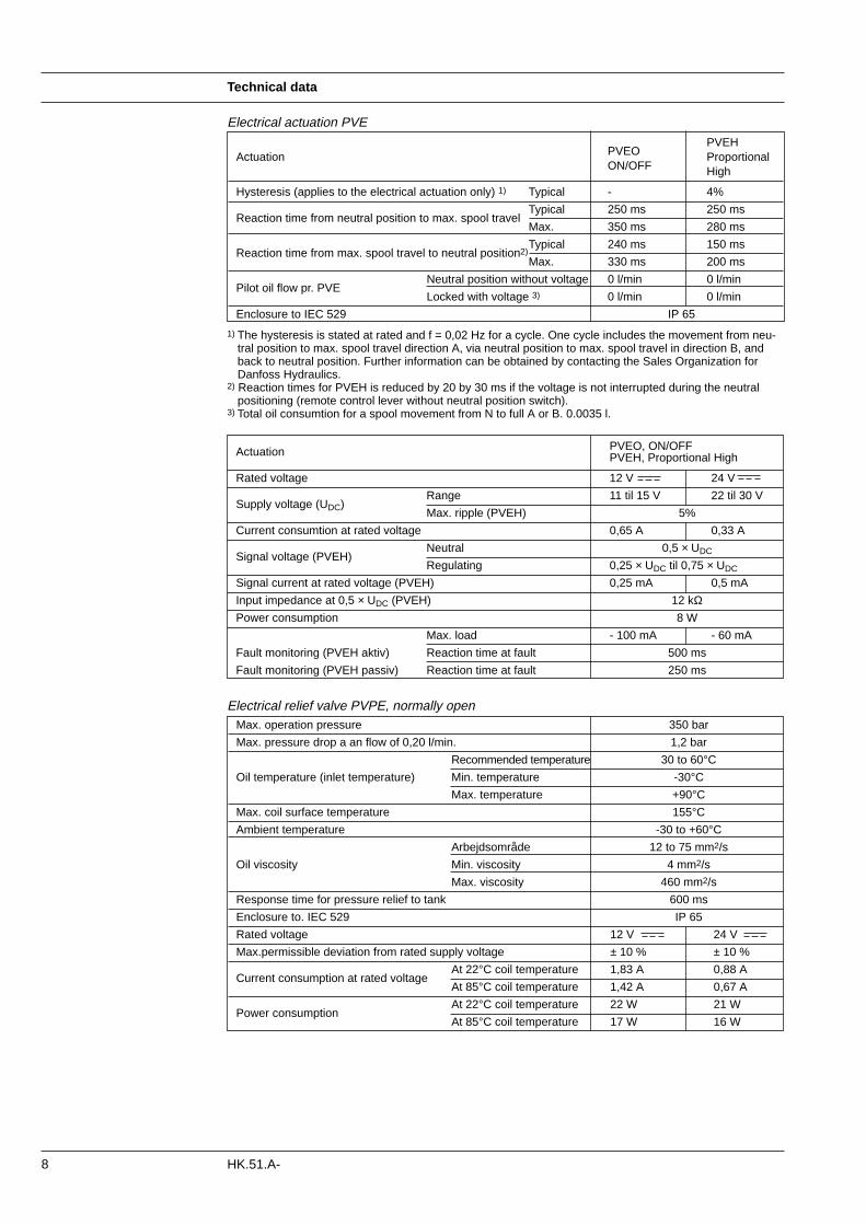
Actuation PVEO, ON/OFFPVEH, Proportional High
Rated voltage 12 V 24 V
Supply voltage (UDC)Range 11 til 15 V 22 til 30 V
Max. ripple (PVEH) 5%
Current consumtion at rated voltage 0,65 A 0,33 A
Signal voltage (PVEH) Neutral 0,5 × UDC
Regulating 0,25 × UDC til 0,75 × UDC
Signal current at rated voltage (PVEH) 0,25 mA 0,5 mA
Input impedance at 0,5 × UDC (PVEH) 12 kΩPower consumption 8 W
Max. load - 100 mA - 60 mA
Fault monitoring (PVEH aktiv) Reaction time at fault 500 ms
Fault monitoring (PVEH passiv) Reaction time at fault 250 ms
Technical data
8 HK.51.A-
PVEOPVEH
ActuationON/OFF
ProportionalHigh
Hysteresis (applies to the electrical actuation only) 1) Typical - 4%
Reaction time from neutral position to max. spool travelTypical 250 ms 250 ms
Max. 350 ms 280 ms
Reaction time from max. spool travel to neutral position2)Typical 240 ms 150 ms
Max. 330 ms 200 ms
Pilot oil flow pr. PVENeutral position without voltage 0 l/min 0 l/min
Locked with voltage 3) 0 l/min 0 l/min
Enclosure to IEC 529 IP 65
Max. operation pressure 350 bar
Max. pressure drop a an flow of 0,20 l/min. 1,2 bar
Recommended temperature 30 to 60°C
Oil temperature (inlet temperature) Min. temperature -30°C
Max. temperature +90°C
Max. coil surface temperature 155°C
Ambient temperature -30 to +60°C
Arbejdsområde 12 to 75 mm2/s
Oil viscosity Min. viscosity 4 mm2/s
Max. viscosity 460 mm2/s
Response time for pressure relief to tank 600 ms
Enclosure to. IEC 529 IP 65
Rated voltage 12 V 24 V
Max.permissible deviation from rated supply voltage ± 10 % ± 10 %
Current consumption at rated voltageAt 22°C coil temperature 1,83 A 0,88 A
At 85°C coil temperature 1,42 A 0,67 A
Power consumption At 22°C coil temperature 22 W 21 W
At 85°C coil temperature 17 W 16 W
Electrical relief valve PVPE, normally open
Electrical actuation PVE
1) The hysteresis is stated at rated and f = 0,02 Hz for a cycle. One cycle includes the movement from neu-tral position to max. spool travel direction A, via neutral position to max. spool travel in direction B, and back to neutral position. Further information can be obtained by contacting the Sales Organization for Danfoss Hydraulics.
2) Reaction times for PVEH is reduced by 20 by 30 ms if the voltage is not interrupted during the neutral positioning (remote control lever without neutral position switch).
3) Total oil consumtion for a spool movement from N to full A or B. 0.0035 l.
9
Electrical actuation
HK.51.A-
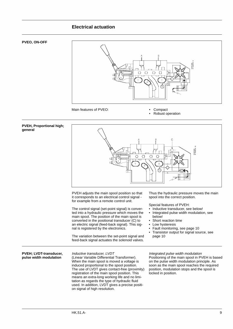
PVEH, Proportional high;general
Thus the hydraulic pressure moves the mainspool into the correct position.
Special features of PVEH:• Inductive transducer, see below!• Integrated pulse width modulation, see
below!• Short reaction time• Low hysteresis• Fault monitoring, see page 10• Transistor output for signal source, see
page 10
PVEH adjusts the main spool position so thatit corresponds to an electrical control signal -for example from a remote control unit.
The control signal (set-point signal) is conver-ted into a hydraulic pressure which moves themain spool. The position of the main spool isconverted in the positional transducer (C) toan electric signal (feed-back signal). This sig-nal is registered by the electronics.
The variation between the set-point signal andfeed-back signal actuates the solenoid valves.
Main features of PVEO:
PVEO, ON-OFF
• Compact• Robust operation
PVEH; LVDT-transducer,pulse width modulation
Integrated pulse width modulationPositioning of the main spool in PVEH is basedon the pulse width modulation principle. Assoon as the main spool reaches the requiredposition, modulation stops and the spool islocked in position.
Inductive transducer, LVDT(Linear Variable Differential Transformer).When the main spool is moved a voltage isinduced proportional to the spool position. The use of LVDT gives contact-free (proximity)registration of the main spool position. Thismeans an extra-long working life and no limi-tation as regards the type of hydraulic fluidused. In addition, LVDT gives a precise positi-on signal of high resolution.
Electrical actuation
10 HK.51.A-
PVEH; fault monitoring Active fault monitoring:• A delay of 500 ms before anything happens.• The solenoid valve bridge will be disabled, –
all solenoids will be released.• An alarm signal is sent out through the
connector.• This state is memorized and continues until
the system is actively reset (by turning off thesupply voltage).
Passive fault monitoring:• A delay of 250 ms before anything happens. • An alarm signal is sent out through the con-
nector.• This state is not memorized. When the erron-
eous state disappears, the alarm signal willturn to passive again. However, the signal willalways be active for a minimum of 100 mswhen triggered.
To prevent the electronics from going into anundefined state, a general supervision of thepower supply and the internal clock frequency ismade:
High supply voltage: The solenoid valves are disabled when the sup-ply voltage is exceeded by 50% (18 V for a 12VPVE and 36 V for a 24 V PVE).
Low supply voltage: The solenoid valves are disabled when the supply voltage falls below 8 V.
Internal clock: The solenoid valves are disabled when the inter-nal clock frequency fails.
All three states are triggered automatically whenthe fault conditions cease.
PVEH; connection to faultmonitoring output
Fault cut-out (red light).
Internal functionInternal function
Note:Different degrees of safety are described on pages19 to 21.
The fault monitoring does notwork if the supply voltage toPVEH is cut off - for example bya neutral position switch (seepage 19).
When using PVEH with passivefault monitoring it is up to thecustomer to decide on thedegree of safety required for thesystem (see page 19).
Example of connected components Example of connected components
A: External relay
B: Solenoid valve (e.g. PVPE)
A: External relay
B: Solenoid valve (e.g. PVPE)
Via an external relay pin 3 can be connectedto an electrically actuated valve which will relieve pump oil flow to tank, e.g. PVPE.
Other connections possible:• a valve to relieve the LS signal• a signal lamp, an alarm horn• pump cut-out, etc.
4.3 The fault monitoring systemA fault monitoring system is provided in all PVEHmodels. The system is available in two versions:
- The active fault monitoring type, which pro-vides a warning signal and deactivates the solenoid valves, and:
- the passive fault monitoring type, which provides a warning signal only. See figure below.
Both active and passive fault monitoring systemsare triggered by 3 main events:
Input signal monitoring: The input signal voltage is continuously monito-red. The legal range is between 15% and 85%of the supply voltage. Outside the range and thissection will switch into an active error state.
Transducer supervision: If one of the wires to the LVDT sensor is brokenor shorted, this section will switch into an activeerror state.
Supervision of the closed loop: The actual position must always correspond tothe demanded position (input signal). When thedistance from neutral to the actual position is longer than the demanded distance, the systemde-tects an error and will switch into an activeerror state. On the other hand, a situation wherethe actual position is closer to neutral than thatdemanded will not cause an error state. Thissituation is considered as “in control”.When an active error state occurs, the faultmonitoring logic will be triggered:
Note: The neutral deadband prevents the output signalfrom releasing the fault monitoring logic, thusstopping the function until the required pilot oilpressure has been developed.
Normal operation (green light).
RedGreen
11
Modules and code numbers
HK.51.A-
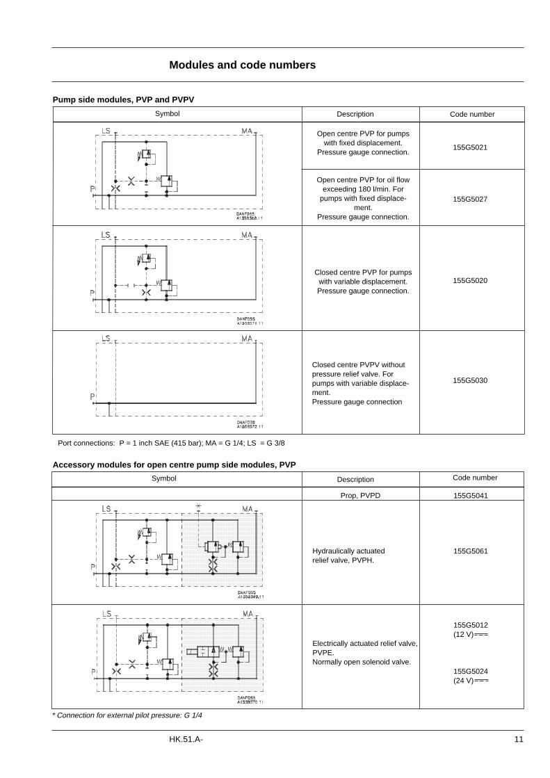
Pump side modules, PVP and PVPV
Code number
Port connections: P = 1 inch SAE (415 bar); MA = G 1/4; LS = G 3/8
Code number
Accessory modules for open centre pump side modules, PVP
Prop, PVPD
Hydraulically actuated relief valve, PVPH.
Electrically actuated relief valve,PVPE.Normally open solenoid valve.
155G5041
155G5061
155G5012(12 V)
155G5024(24 V)
* Connection for external pilot pressure: G 1/4
155G5021
155G5027
155G5020
155G5030
Symbol Description
Open centre PVP for pumpswith fixed displacement.
Pressure gauge connection.
Open centre PVP for oil flowexceeding 180 l/min. For
pumps with fixed displace-ment.
Pressure gauge connection.
Closed centre PVP for pumpswith variable displacement. Pressure gauge connection.
Closed centre PVPV withoutpressure relief valve. Forpumps with variable displace-ment. Pressure gauge connection
Symbol Description
Code number
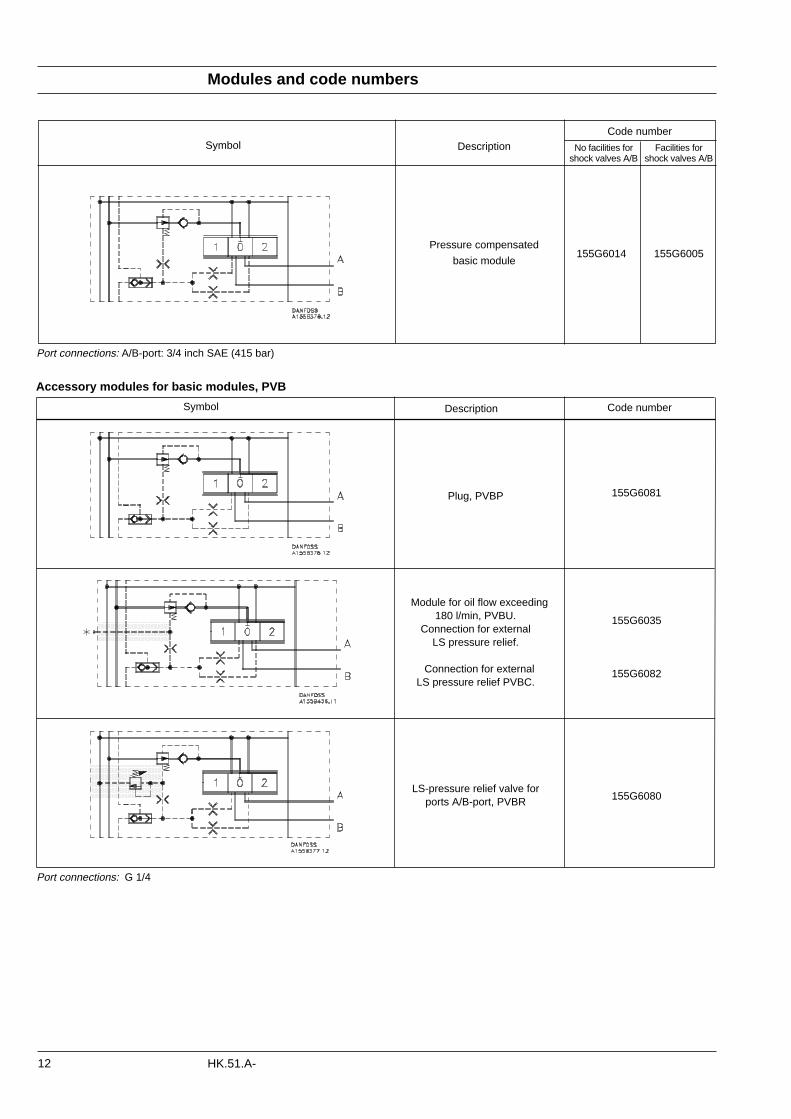
No facilities for Facilities forshock valves A/B shock valves A/B
155G6014 155G6005
Symbol Description
Pressure compensated
basic module
Modules and code numbers
12 HK.51.A-
Accessory modules for basic modules, PVB
Code number
Port connections: G 1/4
155G6081
155G6035
155G6082
155G6080
Symbol Description
Plug, PVBP
Module for oil flow exceeding180 l/min, PVBU.
Connection for external LS pressure relief.
Connection for external LS pressure relief PVBC.
LS-pressure relief valve for ports A/B-port, PVBR
Port connections: A/B-port: 3/4 inch SAE (415 bar)
Description
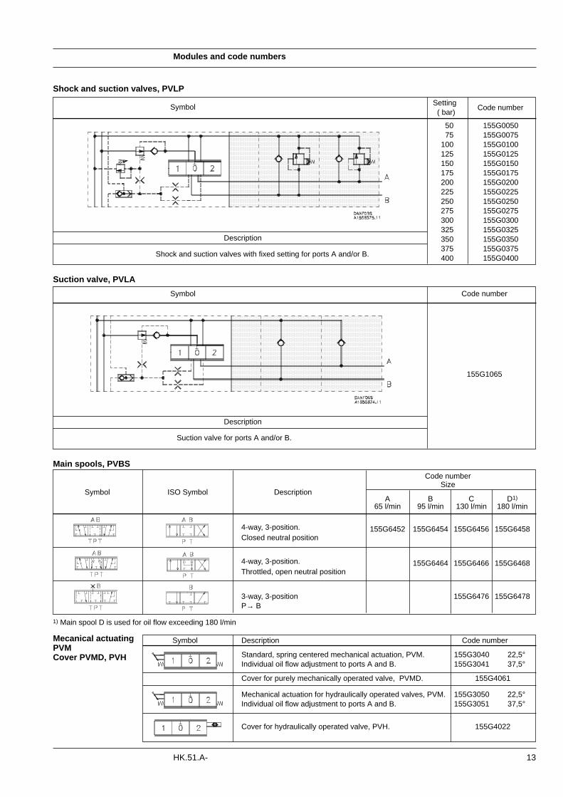
Shock and suction valves with fixed setting for ports A and/or B.
SettingCode number
( bar)
50 155G005075 155G0075
100 155G0100125 155G0125150 155G0150175 155G0175200 155G0200225 155G0225250 155G0250275 155G0275300 155G0300325 155G0325350 155G0350375 155G0375400 155G0400
Modules and code numbers
13HK.51.A-
Shock and suction valves, PVLP
Symbol
Description
Suction valve for ports A and/or B.
Code number
155G1065
Suction valve, PVLA
Symbol
Code number
Symbol ISO Symbol DescriptionSize
A B C D1)
65 l/min 95 l/min 130 l/min 180 l/min
4-way, 3-position. 155G6452 155G6454 155G6456 155G6458Closed neutral position
4-way, 3-position. 155G6464 155G6466 155G6468Throttled, open neutral position
3-way, 3-position 155G6476 155G6478P→ B
Main spools, PVBS
1) Main spool D is used for oil flow exceeding 180 l/min
Symbol Description Code number
Standard, spring centered mechanical actuation, PVM. 155G3040 22,5°Individual oil flow adjustment to ports A and B. 155G3041 37,5°
Cover for purely mechanically operated valve, PVMD. 155G4061
Mechanical actuation for hydraulically operated valves, PVM. 155G3050 22,5°Individual oil flow adjustment to ports A and B. 155G3051 37,5°
Cover for hydraulically operated valve, PVH. 155G4022
Mecanical actuatingPVMCover PVMD, PVH
Modules and code numbers
14 HK.51.A-
Tank side modul, PVT
1) Tank module 155G7040 can easily be rebuilt to be used for pilot oil supply to hydraulically actuated valve. Rebuilding kit 155G7041 contains the necessary springs, spring stops, and O-rings. The remote control unit P port is connected to the PP connection in the tank module.Port connections: T = 1 inch SAE (210 bar); PP = G 3/8; LX = G 3/8
Description
Description 1 PVB 2 PVB 3 PVB 4 PVB 5 PVB 6 PVB 7 PVB 8 PVB
Tie bolts and seals 155G8031 155G8032 155G8033 155G8034 155G8035 155G8036 155G8037 155G8038
Modules for oil flow exceeding 180 l/min
- Basic modulea) Spring behind pressure compensator b) The plug behind the pressure compen-
satorSpring and plug with code number 155G6035 (accessory module, PVBU).
Pump with variable displacement1. Ordering:
Order accessory module 155G6035 and main spool D.
2. Conversion:In closed centre systems a max. oil flow exceeding 180 l/min can be achieved by changing the following basic module parts:a) Spring behind pressure compensator b) The plug behind the pressure compen-
sator The code number of the spring and plug is 155G6035 (accessory module, PVBU).
Electrical actuation, PVE
Pump with fixed displacementl. Ordering:
Order accessory module 155G6035, main spool D, and pump side module 155G5027.
2. Conversion:In open centre systems a max. oil flow exceeding 180 l/min is achieved by chan-ging the following parts in the pump side and basic modules:- Open centre pump side modulea) Pressure adjustment spoolb) The springs behind the pressure adjust -
ment spoolc) The plug behind the pressure adjust
ment spoolParts from kit 155G5035 may be used.
- Closed centre pump side moduleA closed centre pump side module can be changed into an upgraded open centrepump side module by means of kit155G5035.
Symbol DescriptionCode number
12 V 24 V
PVEO;155G4272 155G4274
ON/OFF
PVEH; Proportional High. Pulse width modulation, short reaction155G4072 155G4074
time, low hysteresis, active fault monitoring, inductive transducer.
PVEH; Proportional High. Pulse width modulation, short reaction155G4172 155G4174
time, low hysteresis, passive fault monitoring, inductive transducer.
Assembly kit, PVAS
Symbol Description Code number
Upper Lower part Upper part:
- Without active elements 155G7020
- Without active elements
With LX connection 155G7023
Lower part:
- Without active elements155G7060
Lowerpart Upperpart:
- Without active elements 155G7020' - Without active elements 155G7023
With LX connection
Lower part:Pilot oil supply for electrical 155G70401)
actuations, PVE.Filter mesh: 125µm
15
Technical characteristics
HK.51.A-
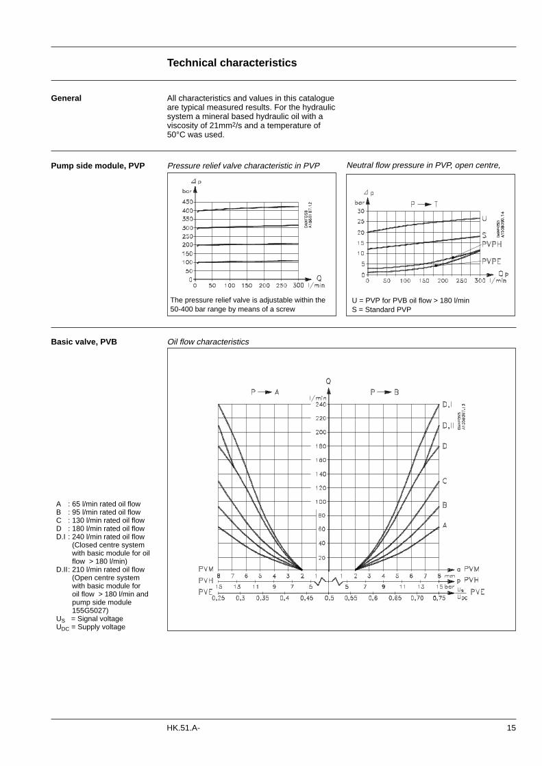
General All characteristics and values in this catalogueare typical measured results. For the hydraulicsystem a mineral based hydraulic oil with aviscosity of 21mm2/s and a temperature of50°C was used.
The pressure relief valve is adjustable within the50-400 bar range by means of a screw
U = PVP for PVB oil flow > 180 l/minS = Standard PVP
Neutral flow pressure in PVP, open centre,
A : 65 l/min rated oil flowB : 95 l/min rated oil flowC : 130 l/min rated oil flowD : 180 l/min rated oil flowD.I : 240 l/min rated oil flow
(Closed centre system with basic module for oil flow > 180 l/min)
D.II: 210 l/min rated oil flow(Open centre system with basic module for oil flow > 180 l/min andpump side module 155G5027)
US = Signal voltageUDC = Supply voltage
Pump side module, PVP Pressure relief valve characteristic in PVP
Basic valve, PVB Oil flow characteristics
Technical characteristics
16 HK.51.A-
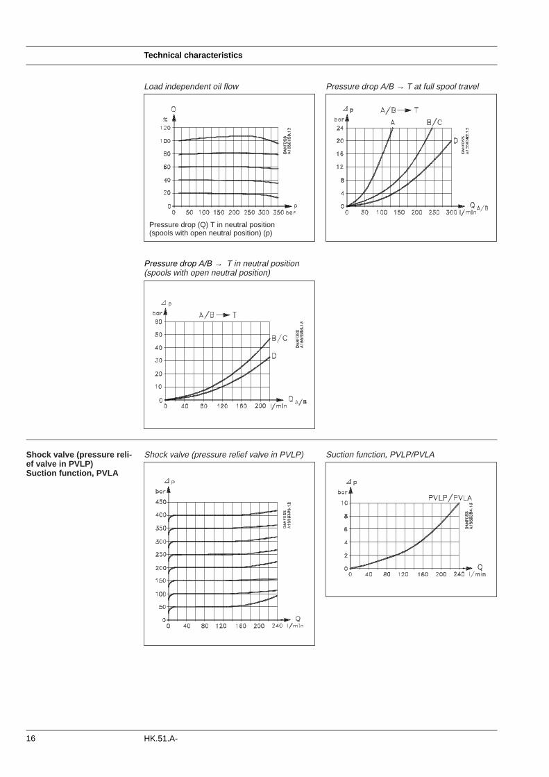
Pressure drop A/B → T in neutral position(spools with open neutral position)
Suction function, PVLP/PVLA
Load independent oil flow Pressure drop A/B → T at full spool travel
Pressure drop (Q) T in neutral position (spools with open neutral position) (p)
Shock valve (pressure reli-ef valve in PVLP)Suction function, PVLA
Shock valve (pressure relief valve in PVLP)
17
Dimensions
HK.51.A-
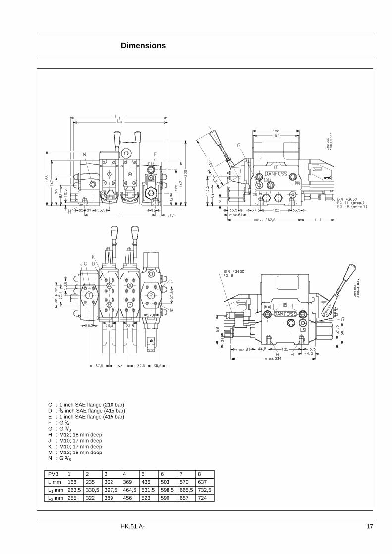
PVB 1 2 3 4 5 6 7 8
L mm 168 235 302 369 436 503 570 637
L1 mm 263,5 330,5 397,5 464,5 531,5 598,5 665,5 732,5
L2 mm 255 322 389 456 523 590 657 724
C : 1 inch SAE flange (210 bar)D : 3⁄4 inch SAE flange (415 bar)E : 1 inch SAE flange (415 bar)F : G 1⁄4G : G 3/8H : M12; 18 mm deepJ : M10; 17 mm deepK : M10; 17 mm deepM : M12; 18 mm deepN : G 3/8
Dimensions
18 HK.51.A-
Lever positions
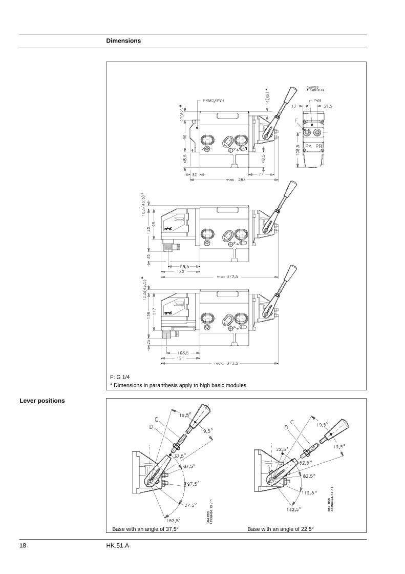
F: G 1/4
* Dimensions in paranthesis apply to high basic modules
Base with an angle of 37,5° Base with an angle of 22,5°
19
System safety
HK.51.A-
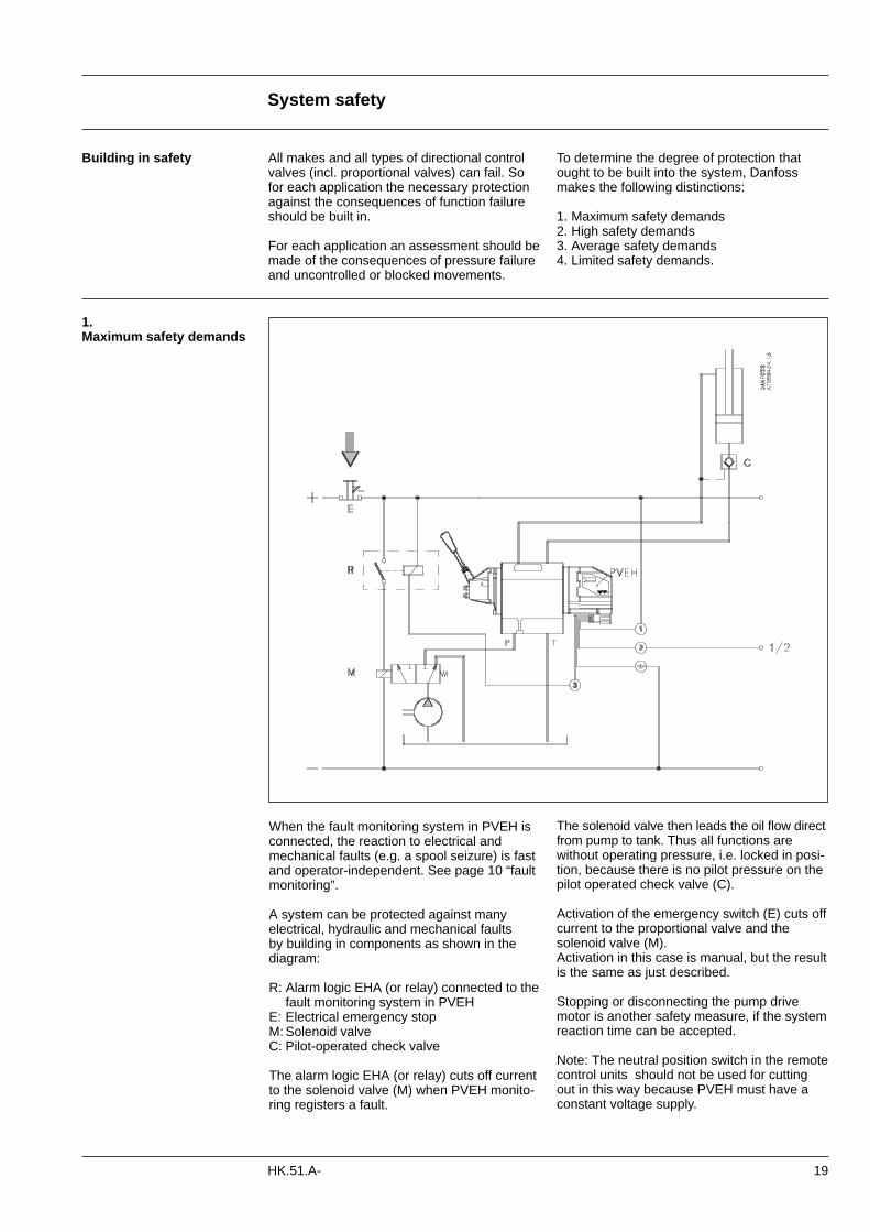
The solenoid valve then leads the oil flow directfrom pump to tank. Thus all functions arewithout operating pressure, i.e. locked in posi-tion, because there is no pilot pressure on thepilot operated check valve (C).
Activation of the emergency switch (E) cuts offcurrent to the proportional valve and thesolenoid valve (M).Activation in this case is manual, but the resultis the same as just described.
Stopping or disconnecting the pump drivemotor is another safety measure, if the systemreaction time can be accepted.
Note: The neutral position switch in the remotecontrol units should not be used for cuttingout in this way because PVEH must have aconstant voltage supply.
1.Maximum safety demands
Building in safety All makes and all types of directional controlvalves (incl. proportional valves) can fail. Sofor each application the necessary protectionagainst the consequences of function failureshould be built in.
For each application an assessment should bemade of the consequences of pressure failureand uncontrolled or blocked movements.
To determine the degree of protection thatought to be built into the system, Danfossmakes the following distinctions:
1. Maximum safety demands2. High safety demands3. Average safety demands4. Limited safety demands.
When the fault monitoring system in PVEH isconnected, the reaction to electrical andmechanical faults (e.g. a spool seizure) is fastand operator-independent. See page 10 “faultmonitoring”.
A system can be protected against many electrical, hydraulic and mechanical faults by building in components as shown in the diagram:
R: Alarm logic EHA (or relay) connected to thefault monitoring system in PVEH
E: Electrical emergency stopM: Solenoid valveC: Pilot-operated check valve
The alarm logic EHA (or relay) cuts off currentto the solenoid valve (M) when PVEH monito-ring registers a fault.
System safety
20 HK.51.A-
2. High safety demands
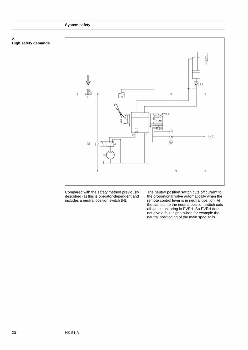
The neutral position switch cuts off current tothe proportional valve automatically when theremote control lever is in neutral position. Atthe same time the neutral position switch cutsoff fault monitoring in PVEH. So PVEH doesnot give a fault signal when for example theneutral positioning of the main spool fails.
Compared with the safety method previouslydescribed (1) this is operator-dependent andincludes a neutral position switch (N).
System safety
21HK.51.A-
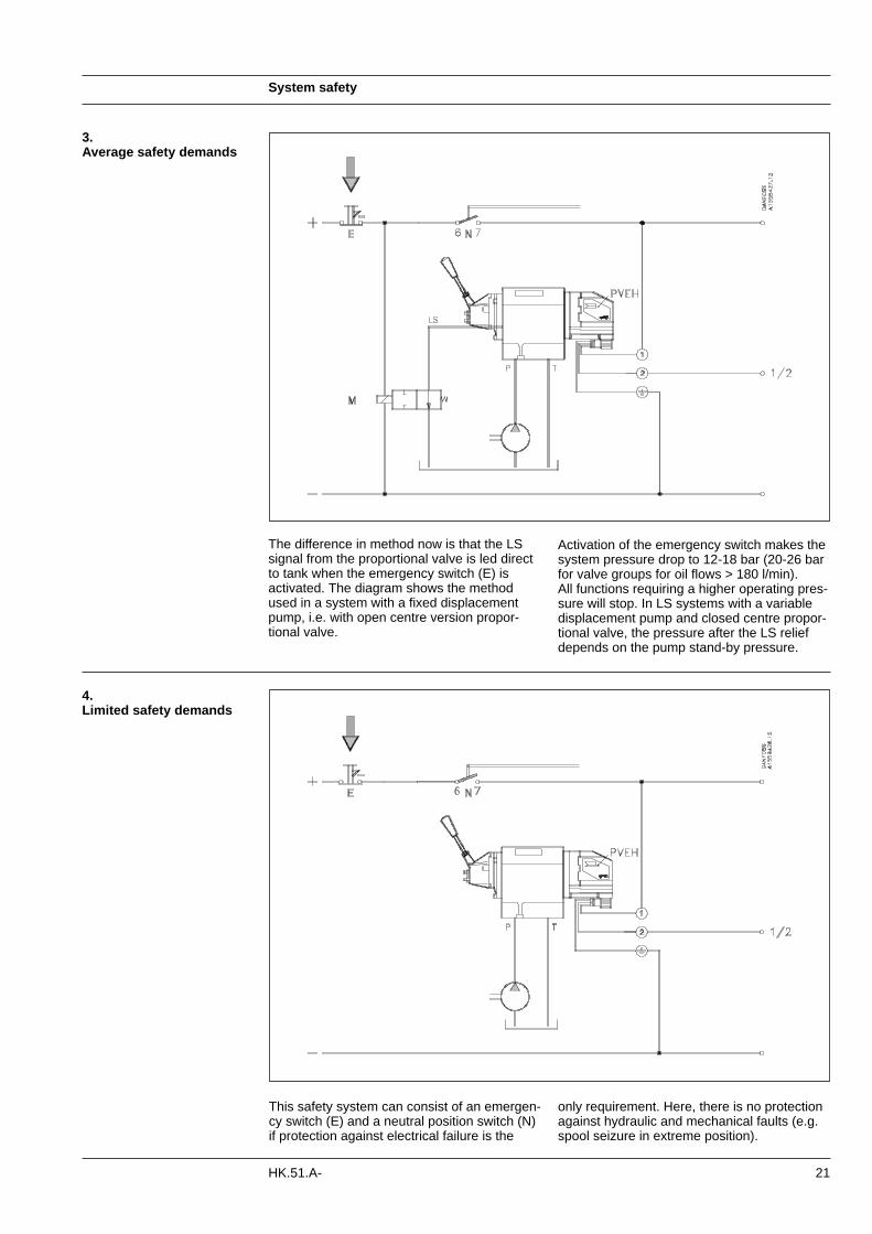
The difference in method now is that the LSsignal from the proportional valve is led directto tank when the emergency switch (E) is activated. The diagram shows the methodused in a system with a fixed displacementpump, i.e. with open centre version propor-tional valve.
Activation of the emergency switch makes thesystem pressure drop to 12-18 bar (20-26 barfor valve groups for oil flows > 180 l/min). All functions requiring a higher operating pres-sure will stop. In LS systems with a variabledisplacement pump and closed centre propor-tional valve, the pressure after the LS reliefdepends on the pump stand-by pressure.
only requirement. Here, there is no protectionagainst hydraulic and mechanical faults (e.g.spool seizure in extreme position).
3.Average safety demands
4.Limited safety demands
This safety system can consist of an emergen-cy switch (E) and a neutral position switch (N)if protection against electrical failure is the
22
Other operating conditions
HK.51.A-
be used with phosphate-esters.The following fluids should only be usedaccording to agreement with the Sales Organisation for Danfoss Hydraulics:• Water-glycol mixtures (HFC fluids)• Water-oil emulsions (HFB fluids)• Oil-water emulsions (HFAE fluids)
Biodegradable oilsDanfoss PVG 120 valves can be used insystems using rape-seed oil. The use of rape-seed oil is conditional on- it complying with the demands on viscosity,
temperature and filtration etc. (see chaptersbelow and technical data page 7).
- the operating conditions being adapted to the recommendations of the oil supplier.
Before using other biodegradable fluids, plea-se consult the Danfoss Sales Organisation forHydraulics.
In our experience a degree of contamination of19/16 can be maintained by using a filter fine-ness as described in the next section.
Filtering
Conversion factors
Internal filtersThe filters built into PVG 120 are not intendedto filter the system but to protect importantcomponents against large particles.Such particles can appear in the system as aresult of pump damage, hose fracture, use ofquick-couplings, filter damage, starting up,contamination, etc.
The filter that protects the pilot supply in thetank side module has a mesh of 125 µm. It isobtainable as a spare part and is easy toreplace.
The filter protecting the essential PVE partshas a mesh of 125 µm.
Oil The main duty of the oil in a hydraulic system is to transfer energy; but it must also lubricatethe moving parts in hydraulic components, pro-tect them against corrosion, and transport dirtparticles and heat out of the system.It is therefore important to choose the correctoil with the correct additives. This gives pro-blem-free operation and long working life.
Mineral oilFor systems with PVG 120 valves Danfossrecommends the use of mineral-based hydrau-lic oil containing additives:Type H-LP (DIN 51524) or HM (ISO 6743/4).
Non-flammable fluidsPhosphate-esters (HFDR fluids) can be usedwithout special precautions. However, dynamicseals must be replaced with FPM (Viton) seals.Please contact the Sales Organisation for Danfoss Hydraulics if the PVG 120 valve is to
Oil filtration must prevent the particle contentfrom exceeding an acceptable level, i.e. anacceptable degree of contamination.Maximum contamination for Danfoss PVG 120is 19/16 (see ISO 4406. Calibration in accordance with the ACFTD
Particle content, degree ofcontamination
Effective filtration is the most important pre-condition in ensuring that a hydraulic systemperforms reliably and has a long working life.Filter manufacturers issue instructions andrecommendations. It is advisable to followthem.
System filtersWhere demands for safety and reliability arevery high a pressure filter with bypass andindicator is recommended. Experience showsthat a 10 µm nominal filter (or finer) or a 20 µm absolute filter (or finer) is suitable.It is our experience that a return filter isadequate in a purely mechanically operatedvalve system.
The fineness of a pressure filter must be selected as described by the filter manufactu-rer so that a particle level of 19/16 is not exce-eded. See “Particle content, degree of conta-mination”, above. The filter must be fitted with pressure gauge ordirt indicator to make it possible to check thecondition of the filter.
1 daNm = 88.51 lbf in1 daN = 2.248 lbf1 bar = 14.50 lbf/in2
1 mm = 0.0394 in
1 cm3 = 0.061 in3
1 l = 0.22 gallon, UK1 l = 0.264 gallon, US°F = 1.8 × °C + 32

23
Order specification
HK.51.A-
c: Cover for mechanical operation PVMDCover for hydraulic operation PVHElectrical actuations PVEO and PVEH
b: Shock and suction valve PVLPSuction valve PVLA
9: Tank side module PVT10: Assembly kit PVAS
Please state:• Code numbers of all modules required• Required setting (p) for pump side module• Required setting of LSA/B pressure relief
valves, if accessory module PVBR is ordered.
Order form An order form for Danfoss PVG 120 hydraulicvalve is shown below. The form can be obtai-ned from the Danfoss Hydraulics Sales Orga-nisation.The module selection chart on the next pageand the order form are divided into fields.Each module has its own field:0: Pump side modules PVPd: Accessory modules PVPD, PVPH and PVPE1-8:Basic modules PVBe: Main spools PVBSf: Accessory modules PVBP, PVBR, PVBU
and PVBCa: Mechanical actuation PVM
ReorderingThe space at the top right-handcorner of the form is for Danfossto fill in. The code number forthe whole of the specified valvegroup (PVG No.) is enteredhere.
In the event of a repeat order allyou have to do is enter the num-ber Danfoss has given on theinitial confirmation of order.
Note:If PVG 120 is to be used withphosphate-esters this must bestated on the order form (seealso page 22, “Non-flammablefluids”).
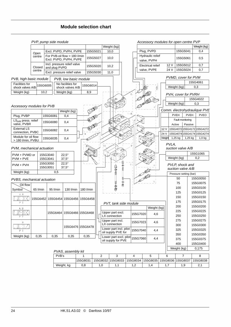
PVMD, cover for PVM
Accessory modules for open centre PVP
24
Module selection chart
HK.51.A3.02 © Danfoss 10/97
Oil flow
Symbol 65 l/min 95 l/min 130 l/min 180 l/min
155G6452 155G6454 155G6456 155G6458
155G6464 155G6466 155G6468
155G6476 155G6478
Weight (kg) 0,35 0,35 0,35 0,35
PVBS, mechanical actuation
PVP, pump side moduleWeight (kg)
Excl. PVPD, PVPH, PVPE 155G5021 10,0Open
For PVB-oil flow > 180 l/mincentreExcl. PVPD, PVPH, PVPE 155G5027 10,0
ClosedIncl. pressure relief valve
centreand plug PVPD 155G5020 10,2
Excl. pressure relief valve 155G5030 11,0
Weight (kg)
Plug, PVPD 155G5041 0,4
Hydraulic relief
valve, PVPH155G5061 0,5
Electrical relief 12 V 155G5012 0,7
valve, PVPE 24 V 155G5024 0,7
PVB, high basic moduleFacilities for 155G6005shock valves A/B
Weight (kg) 10,2
No facilities for 155G6014shock valves A/B
Weight (kg) 8,9
PVB, low basic module
PVM + PVMD or 155G3040 22,5°PVM + PVE 155G3041 37,5°
155G3050 22,5°PVM + PVH155G3051 37,5°
Weight (kg) 0,5
Accessory modules for PVBWeight (kg)
Plug, PVBP 155G6081 0,4
LSA/B press. relief 155G6080 0,4valve, PVBR
External LS 155G6082 0,4connection, PVBC
Module for oil flow 155G6035 0,4> 180 l/min, PVBU
155G4061
Weight (kg) 0,3
PVM, mechanical actuation
PVLP, shock and suction valve A/B
Pressure setting (bar)
50 155G0050
75 155G0075
100 155G0100
125 155G0125
150 155G0150
175 155G0175
200 155G0200
225 155G0225
250 155G0250
275 155G0275
300 155G0300
325 155G0325
350 155G0350
375 155G0375
400 155G0400
Weight (kg) 0,175PVAS, assembly kit
155G4022
Weight (kg) 0,3
155G1065Weight (kg) 0,2
PVLA, suction valve A/B
PVH, cover for PVRH
PVT, tank side moduleWeight (kg)
Upper part excl. 155G7020 4,6LX connection
Upper part incl. 155G7023 4,6LX connection
Lower part incl. pilot 155G7040 4,4oil supply PVE for
Lower part excl. pilot 155G7060 4,4oil supply for PVE
PVB’s 1 2 3 4 5 6 7 8
155G8031 155G8032 155G8033 155G8034 155G8035 155G8036 155G8037 155G8038
Weight, kg 0,8 1,0 1,1 1,2 1,4 1,7 1,9 2,1
PVEH PVEH PVEO
Fault monitoring
Active Passive
12 V 155G4072 155G4172 155G4272
24 V 155G4074 155G4174 155G4274
Weight 1,25 kg 1,25 kg 1,0 kg
Comm. électrohydraulique PVE


![[4] Kolben- StangendichtungenKolben- Stangendichtungen für Hydraulik & Pneumatik INHALT | HydrAuLIK STANgeN- KoLbeNdIcHTuNg HydrAuLIK STANgeNdIcHTuNg HydrAuLIK STANgeNdIcHTuNg AbSTreIfer](https://img.pdfslide.tips/doc/110x75/60c8cff8766790119a3be84c/4-kolben-stangendichtungen-kolben-stangendichtungen-fr-hydraulik-pneumatik.jpg)