Embed Size (px)
Citation preview

LTE-A MOBILE RELAY HANDLING:
ARCHITECTURE ASPECTS報告者:洪偉晉
班級:碩研資管一甲
學號:MA590203
課程:南台科大資管所無線網路與行動計算
授課老師:陳偉業
報告出處:Wireless Conference (EW), Proceedings of the 2013 19th European

INTRODUCTION

INTRODUCTION
• Support for fixed cellular relays was introduced in 3GPP Rel’ 10 (LTE-Advanced
• coverage of high data rates
• the cell-edge throughput
• temporary network deployment
• In the 3GPP Technical Report [1] different architecture alternatives have been
analyzed.
• proxy S1/X2 has more benefits in compare with other three alternatives
• This alternative was selected as the baseline architecture for Rel’ 10

INTRODUCTION
• This paper is devoted to architecture issues concerning mobile relay handling that
imposes additional network requirements
• persistent IP connectivity during relay mobility
• group mobility for mobile terminals attached to the mobile relay
• Other architecture alternatives could have more advantages
• review the 3GPP fixed relay architecture alternatives
• select the most appropriate one for enabling mobile relay (MR)
• compare control and user planes of different architecture alternatives
• consider network scenarios based
• latency budget analysis

A USER AND CONTROL PLANE ASPECTS OF DIFFERENT ARCHITECTURE
ALTERNATIVES

A USER AND CONTROL PLANE ASPECTS OF DIFFERENT ARCHITECTURE ALTERNATIVES
• Compare the architecture Alt 2 (Proxy S1/X2) and Alt1 (Full-L3 relay)
• they present two different philosophies
• Alt 2 (Proxy S1/X2)
• the S-GW/P-GW functionality serving the relay is embedded in the DeNB
• the relay S1/X2 interfaces in the architecture are terminated in the DeNB
• Alt 1 (Full-L3 relay)
• the S-GW/P-GW entity serving the relay is separated from the DeNB
• the relay is transparent for DeNB

A USER AND CONTROL PLANE ASPECTS OF DIFFERENT ARCHITECTURE ALTERNATIVES
• User plane aspects
• Alt 2(Proxy S1/X2)
• the S-GW/P-GW functionality related to the relay is located within the DeNB
• allows avoiding situations when packets traverse via two S-GW/P-GWs
• the home eNB GW functionality is added into the DeNB
• results in the “ProxyS1/X2” architecture
• a GTP tunnel establishment per User Equipment (UE) bearer
• Alt 1(Full-L3 relay)
• the S-GW/P-GW functionality serving the relay is out of the DeNB
• the user plane packets are delivered to/from a UE via two gateways
• this architecture was not selected as the baseline one for the fixed relay
• the packet forwarding path is longer in this architecture that can lead to large latency

A USER AND CONTROL PLANE ASPECTS OF DIFFERENT ARCHITECTURE ALTERNATIVES
• User plane aspects
• Alt 1(Full-L3 relay)
• the separation of the S-GW/P-GW from the DeNB can bring some benefits
• this S-GW/P-GW can be considered as a stable “IP anchor point” to support mobility of the relay
• One more specific feature of the Alt 1
• transparence of the DeNB for the full L3 relay
• a GTP tunnel per UE bearer is entire without any switching in the DeNB and goes from the S-
GW/P-GW serving the UE directly to the relay

A USER AND CONTROL PLANE ASPECTS OF DIFFERENT ARCHITECTURE ALTERNATIVES
• Control plane aspects
• Alt 2
• the S1-AP messages are sent in two steps:
• between the MME serving the UE and the DeNB
• between the DeNB and the relay
• The messages are encapsulated by SCTP/IP in the MME serving the UE
• transferred over an EPS data bearer of the relay
• the S-GW/P-GW functionality for the relay’s EPS bearers is incorporated into the DeNB
• Alt 1
• the S1-AP signalling messages are sent in one step directly between the MME serving the UE and the relay
• the S1 signalling messages sent between the relay and the MME serving the UE are mapped on user plane EPS
bearers of the relay

A USER AND CONTROL PLANE ASPECTS OF DIFFERENT ARCHITECTURE ALTERNATIVES
• Control plane aspects
• Alt 2
• In the architecture Alt 2 there is a single S1 interface relation between the relay and the DeNB
• there is one S1 interface relation between the DeNB and each MME (serving the UEs) in the MME
pool
• the relay has to maintain only one S1 interface (to the DeNB)
• the DeNB maintains one S1 interface to each MME in the respective MME pool
• All S1 signalling connections between relay and MMEs are processed by the DeNB for all UE-
dedicated procedures
• All non-UE-dedicated S1-AP procedures are terminated at the DeNB, and handled locally
between the relay and the DeNB, and between the DeNB and the MME

A USER AND CONTROL PLANE ASPECTS OF DIFFERENT ARCHITECTURE ALTERNATIVES
• Control plane aspects
• Alt 1
• there is one S1 signalling relation for each connected UE on the given S1 interface between the
relay and the MME serving the UE
• the relay has to maintain one S1 interface relation to each MME in the respective MME pool
• The S1 interface and the signalling connections go through the DeNB transparently

A USER AND CONTROL PLANE ASPECTS OF DIFFERENT ARCHITECTURE ALTERNATIVES

A USER AND CONTROL PLANE ASPECTS OF DIFFERENT ARCHITECTURE ALTERNATIVES

RELAY MOBILITY SCENARIOS BASED ON DIFFERENT ARCHITECTURES
RELAY MOBILITY SCENARIOS BASED ON DIFFERENT ARCHITECTURES
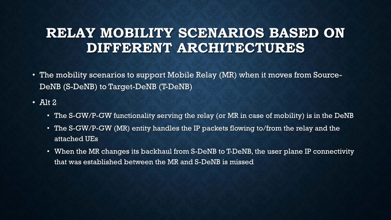
• The mobility scenarios to support Mobile Relay (MR) when it moves from Source-
DeNB (S-DeNB) to Target-DeNB (T-DeNB)
• Alt 2
• The S-GW/P-GW functionality serving the relay (or MR in case of mobility) is in the DeNB
• The S-GW/P-GW (MR) entity handles the IP packets flowing to/from the relay and the
attached UEs
• When the MR changes its backhaul from S-DeNB to T-DeNB, the user plane IP connectivity
that was established between the MR and S-DeNB is missed

RELAY MOBILITY SCENARIOS BASED ON DIFFERENT ARCHITECTURES

RELAY MOBILITY SCENARIOS BASED ON DIFFERENT ARCHITECTURES

RELAY MOBILITY SCENARIOS BASED ON DIFFERENT ARCHITECTURES
• Alt 2
• The group mobility for the attached UEs is not supported.
• The MR needs to obtain a new IP address and establish the IP connectivity with T-DeNB.
• This phase of the attach procedure includes
• relay backhaul reconfiguration that is completed by OAM (Operations, Administration and
Maintenance)
• relay-initiated S1/X2 setup
• S1/X2 eNB configuration update
• one more problem because of the IP connectivity is lost when the MR

RELAY MOBILITY SCENARIOS BASED ON DIFFERENT ARCHITECTURES
• Alt 2
• When the MR goes from the S-DeNB to the T-DeNB the connection between the MR and its
OAM is interrupted
• Alarms in the MR generate bursts of high-priority traffic and have to be transported in real
time
• Not appropriate at it is to support these requirements and some enhancements are
needed.

RELAY MOBILITY SCENARIOS BASED ON DIFFERENT ARCHITECTURES
• Alt 1
• When the MR moves from the S-DeNB to the T-DeNB, the S-GW/P-GW of the MR serves as
anchor
• IP connectivity is handled through retaining a stable “IP anchor point” in the network
• The IP address of the MR is not changed during the movement.
• As a result group mobility for the attached UEs is supported
• It is not required also to perform the network re-entry at the T-DeNB

MOBILE RELAY HANDOVER PROCEDURE FOR DIFFERENT ARCHITECTURE
ALTERNATIVES

MOBILE RELAY HANDOVER PROCEDURE FOR DIFFERENT ARCHITECTURE ALTERNATIVES
• Concentrate on the handover procedure when the mobile relay moves between S-DeNB
and T-DeNB
• the relay supports a subset of the UE functionality in order to be wirelessly connected to
the DeNB
• the legacy UE handover procedure can be re-used as a basis for the mobile relay handover
procedure
• like the legacy UE handover procedure includes three phases
• handover preparation
• handover execution
• handover preparation
MOBILE RELAY HANDOVER PROCEDURE FOR DIFFERENT ARCHITECTURE ALTERNATIVES
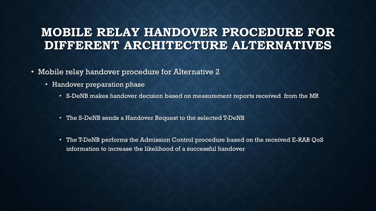
• Mobile relay handover procedure for Alternative 2
• Handover preparation phase
• S-DeNB makes handover decision based on measurement reports received from the MR
• The S-DeNB sends a Handover Request to the selected T-DeNB
• The T-DeNB performs the Admission Control procedure based on the received E-RAB QoS
information to increase the likelihood of a successful handover

MOBILE RELAY HANDOVER PROCEDURE FOR DIFFERENT ARCHITECTURE ALTERNATIVES

MOBILE RELAY HANDOVER PROCEDURE FOR DIFFERENT ARCHITECTURE ALTERNATIVES
• Mobile relay handover procedure for Alternative 2
• Handover execution phase
• The RRC message contains RRC Connection Reconfiguration information to be sent by the S-
DeNB towards the MR for the relay backhaul reconfiguration specified for the Un interface
• The S-DeNB sends the SN Status Transfer to the T-DeNB taking into account the Un interface
specific functionality
• After receiving the RRC Connection Reconfiguration message
• the MR completes synchronization and reconfiguration of the relay backhaul to T-DeNB
• The T-DeNB performs uplink allocation towards the MR.
• The MR sends the RRC Connection Reconfiguration Complete message to the T-DeNB to confirm the
handover

MOBILE RELAY HANDOVER PROCEDURE FOR DIFFERENT ARCHITECTURE ALTERNATIVES
• Mobile relay handover procedure for Alternative 2
• Handover execution phase
• The MR configuration is downloaded from the OAM system through the T-DeNB
• The S1/X2 setup is initiated between the MR and the T-DeNB
• T-DeNB updates its configuration on the S1/X2 interfaces

MOBILE RELAY HANDOVER PROCEDURE FOR DIFFERENT ARCHITECTURE ALTERNATIVES
• Mobile relay handover procedure for Alternative 2
• Handover completion phase
• The mobile relay sends a Path Switch Request
• The S-GW/P-GW of the UEs switches downlink path and sends packet data to the T-DeNB sends
one or more "end marker" packets on the old path to the S-DeNB
• The S-GW/P-GW of the UEs issues a User Plane Response to the MME (UEs) which sends a Path
Switch Acknowledge message towards the mobile relay
• if the UEs attached to the mobile relay are served by different S-GWs/MMEs, the above items of the
handover completion phase are completed for each S-GW/MME serving the UEs
• the S-DeNB can release related resources associated to the MR context

MOBILE RELAY HANDOVER PROCEDURE FOR DIFFERENT ARCHITECTURE ALTERNATIVES

MOBILE RELAY HANDOVER PROCEDURE FOR DIFFERENT ARCHITECTURE ALTERNATIVES
• Mobile relay handover procedure for Alternative 1
• The handover preparation phase is similar to one for the Alternative 2
• Handover execution phase is also similar excepting last three items
• there is no need in this case for the MR to download configuration from the OAM
• initiate the S1/X2 setup
• it is not required for the T-DeNB to update its configuration on the S1/X2 interfaces

MOBILE RELAY HANDOVER PROCEDURE FOR DIFFERENT ARCHITECTURE ALTERNATIVES
• Mobile relay handover procedure for Alternative 1
• Handover completion phase
• The T-DeNB sends a Path Switch Request to the MME serving the MR to inform that the MR was
detached from the S-DeNB
• The MME serving the MR issues a User Plane Update Request to the S-GW/P-GW serving the MR
to switch downlink path. Now packet data are sent to the T-DeNB
• The S-GW/P-GW of the MR sends one or more "end marker" packets on the old path to the S-
DeNB to release resources related to the user plane
• It also issues a User Plane Update Response to the MME of the MR which sends a Path Switch
Request Acknowledge to the T-DeNB.

MOBILE RELAY HANDOVER PROCEDURE FOR DIFFERENT ARCHITECTURE ALTERNATIVES
• The handover procedure for the MR moving between S-DeNB and T-DeNB based in the
architecture Alt 1 looks more simplified than one based on the architecture Alt 2
• it does not include the network re-entry procedure for the MR at T-DeNB
• the separated S-GW/P-GW (MR) acting as the MR stable IP anchor point
• architecture Alt 2
• the user plane is handled by the S-GW/P-GW of a UE
• The UEs attached to the MR can be connected to different the S-GW/P-GWs (UE) that can be under
control of different MMEs (UE)
• It can lead to more complex and time-consuming procedure because of multiple data path switching

COMPARATIVE ANALYSIS WITH OTHERALTERNATIVES

COMPARATIVE ANALYSIS WITH OTHERALTERNATIVES
• We briefly re-analyze the other architectural solutions, Alt 3 and Alt 4
• Alt 3
• that relay bearers are terminated in the DeNB
• Alt 4
• that the user plane of the S1 interface is terminated in the DeNB
• These alternatives have the same crucial problems as the architecture Alt 2
• the S-GW/P-GW functionality serving the relay in the architectures Alt 3 and Alt 4 is embedded into the
DeNB
• no “IP anchor point” handling IP connectivity for the mobile relay performing the handover procedure
• Some enhancements can be done to support the relay mobility in the Alternatives 2, 3, and 4
PERFORMANCE EVALUATION OF BASIC RELAY ARCHITECTURE SCENARIOS
(LATENCY ANALYSIS)

PERFORMANCE EVALUATION OF BASIC RELAYARCHITECTURE SCENARIOS (LATENCY
ANALYSIS)

PERFORMANCE EVALUATION OF BASIC RELAYARCHITECTURE SCENARIOS (LATENCY
ANALYSIS)

PERFORMANCE EVALUATION OF BASIC RELAYARCHITECTURE SCENARIOS (LATENCY
ANALYSIS)
• the handover procedure duration when the MR moves from S-DeNB to T-DeNB is
analyzed for the Alt 1 and Alt 2.
• Assumed that one-way transmission time between the relay and the DeNB (2 ms) is the
same as the transmission time between a UE and a relay/Enb
• OAM configuration downloading for the MR takes 7 ms
• S1/X2 setup initiation between the MR and the T-DeNB is around 17 ms
• The T-DeNB configuration update takes 2 ms.

PERFORMANCE EVALUATION OF BASIC RELAYARCHITECTURE SCENARIOS (LATENCY
ANALYSIS)
• As seen from Table I
• the latency to perform the MR handover procedure from S-DeNB to T-DeNB for the Alt 1 is
about 1.5 times less than for the Alt 2
• The handover procedure for the Alt 2 requires additional operations when MR performs the
network re-entry at the TDeNB
• Alt 2, it is supposed in Table I that all UEs attached to the MR are under the same S-
GW/MME serving the UEs
• If they are connected to different S-GWs/MMEs it can lead to multiple downlink data path
switching
• The architecture Alt 1 shows better performance in a mobile relay network.

CONCLUSIONS

CONCLUSIONS
• In the study we have reviewed the basic 3GPP fixed relay architecture alternatives
• That for mobile relay changing its backhaul link (Un interface) from Source-DeNB to
Target-DeNB
• Alt 1 (a full L3 relay) has more benefits than other architecture alternatives
• The architecture Alt 1 supposes the stable IP anchor point supporting continuous IP
connectivity for the mobile relay.
• does not require the time-consuming relay re-attach procedure when backhaul link is re-
established to TDeNB
• it handles interworking between the mobile relay and OAM without connectivity interruption
• the handover procedure does not require some downlink data path switches related to different
S-GWs/MMEs serving UEs.