Embed Size (px)
Citation preview

M. Biagini, INFN-LNFeeFACT, Daresbury, October 27th 2016
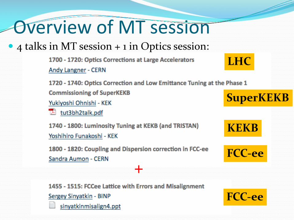
OverviewofMTsession� 4 talks in MT session + 1 in Optics session:
+
LHC
SuperKEKB
KEKB
FCC-ee
FCC-ee
Whyweneedmachinetuning� Design a lattice is the easy part… making this lattice to deliver expected
performances is the real job� Unavoidable machine errors (magnet misalignments, field errors,
BPMs, …) must absolutely be corrected in order to achieve machine performances: low emittances and luminosity in colliders
� Errors affect mostly vertical emittance which is zero in a ”perfect” lattice� Errors must be included in Dynamic Aperture calculations à re-
optimization needed� ee-Factories can profit of the synergies with low emittance Synchrotron
Light Sources à available tools, codes comparison, methods� Machine model must be accurate in order to be able to reproduce the
measurements and to perform needed corrections and tuning� Luminosity tuning at ee-Factories is essential to reach and keep the
design performances
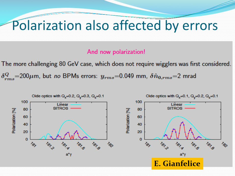
E. Gianfelice
Polarizationalsoaffectedbyerrors

K. Oide

D. Einfeld
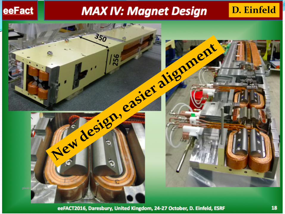
D. Einfeld
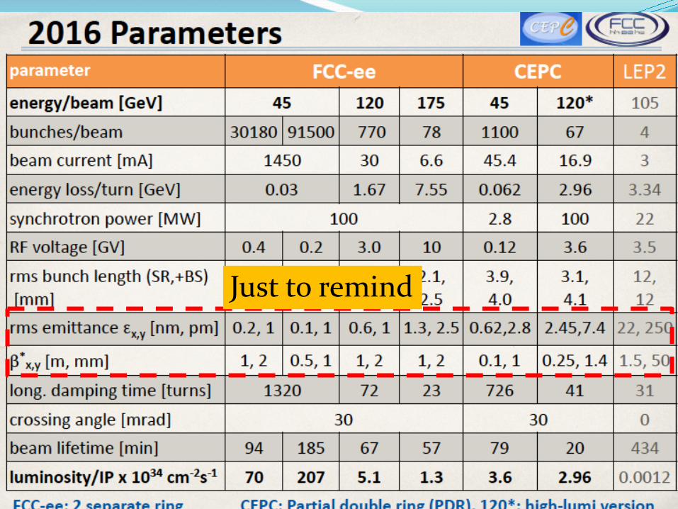
Just to remind

Furthercomplication…
K. Oide
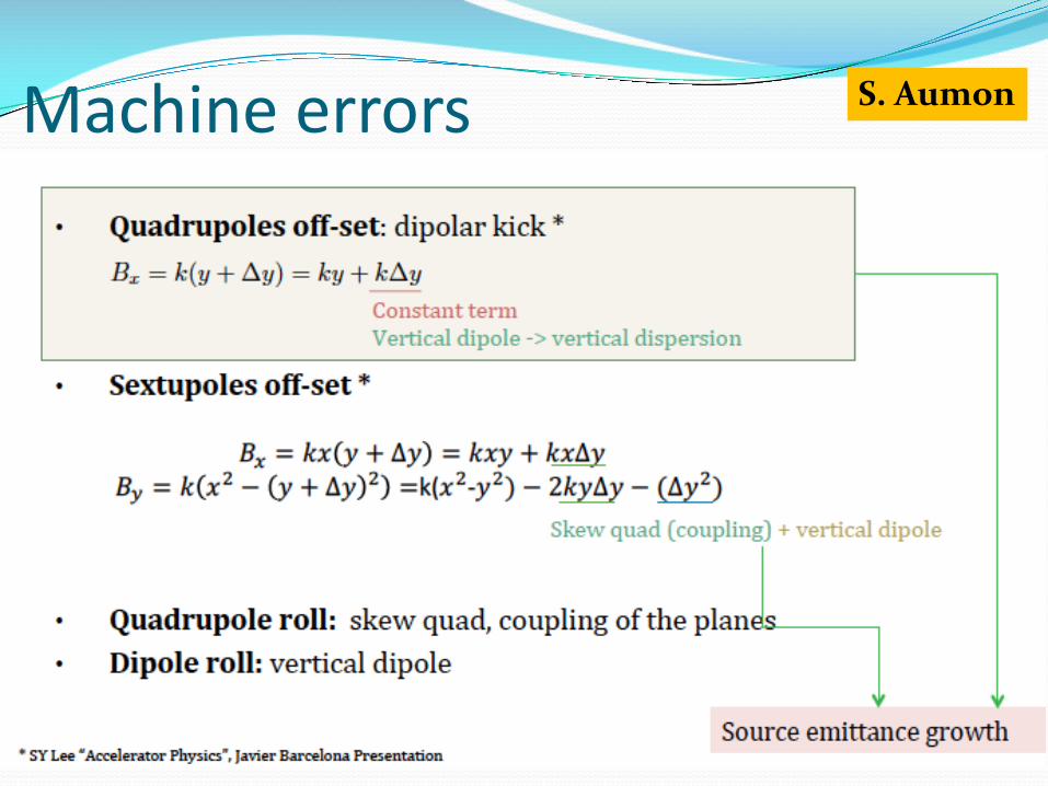
Machineerrors S. Aumon
K. Oide
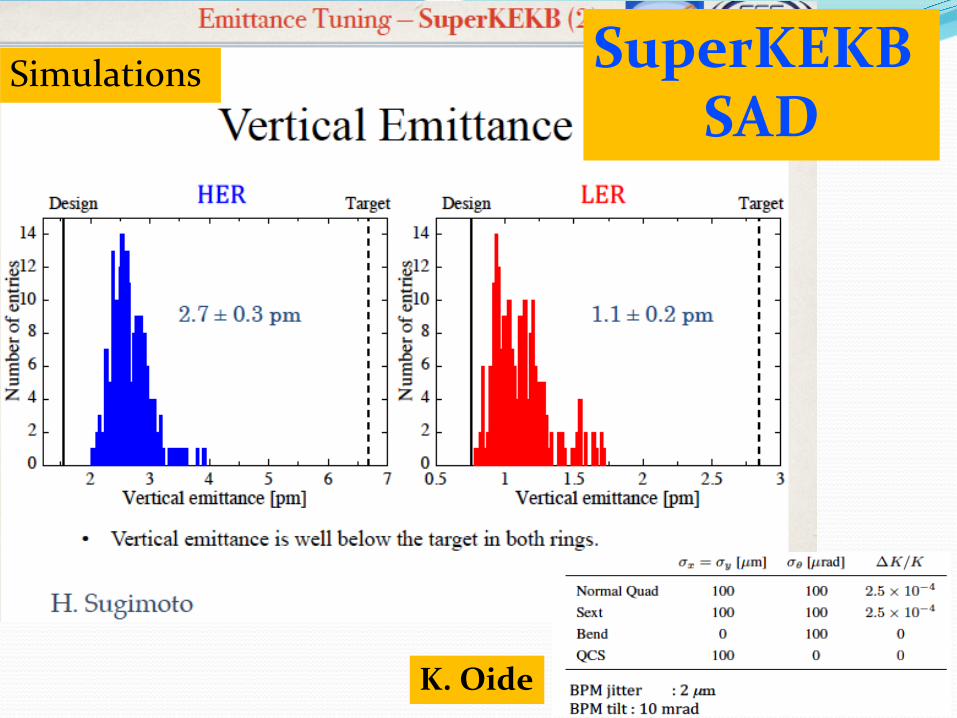
Simulations SuperKEKBSAD

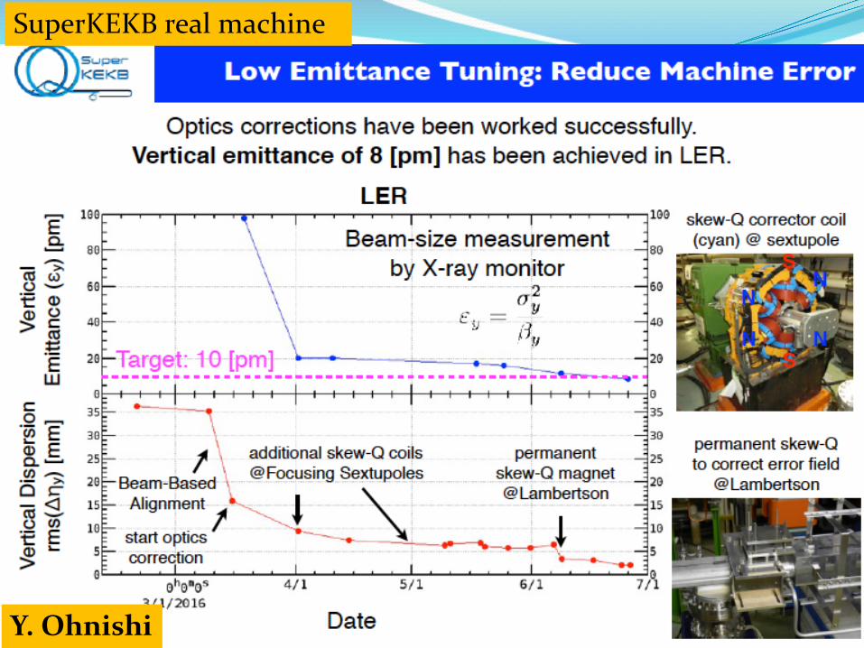
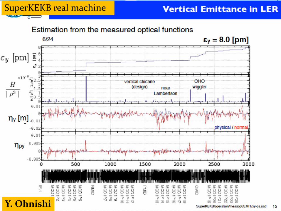
SuperKEKB real machine
SADY. Ohnishi
SuperKEKB real machine
Y. Ohnishi
SuperKEKB real machine
Y. Ohnishi

SuperKEKB real machine
Understand your machine à Model correction ! Understanding OFF-momentum optics is needed for DA optimization
Y. Ohnishi
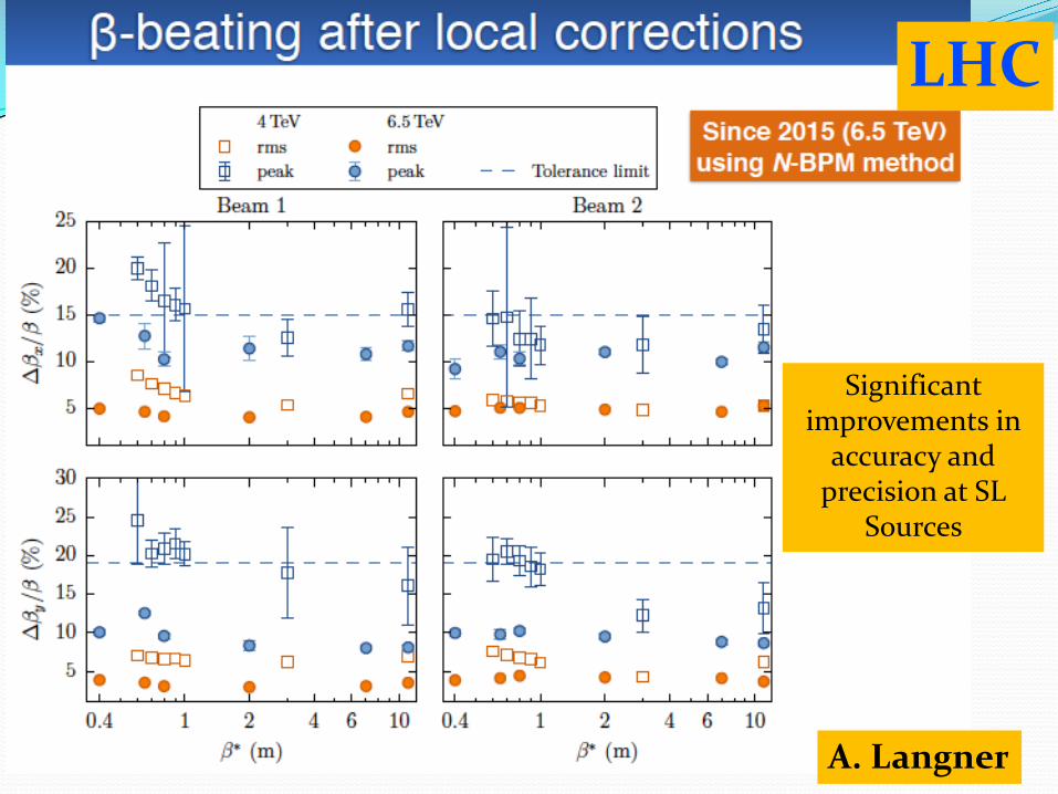
LHC
A. Langner
Significant improvements in
accuracy and precision at SL
Sources

LHC
A. Langner

18
MisalignmentsofelementsEmittancesratio
� Misalignments of elements: � BPM: FF ΔX,Y = 25 um, CCS ΔX,Y = 50 um, ARC ΔX,Y = 100 um;� Dipole: ΔTilt = 200 urad;� Quadrupole: FF ΔX,Y = 25 um, CCS ΔX,Y = 100 um, ARC ΔX,Y = 100 um;� Sextupole: CCS ΔX,Y = 100 um, ARC ΔX,Y = 100 um;
� <εy / εx> is reduced from 15 % to 1.4 % after CO, betatroncoupling and vertical dispersion correction.
0
0.05
0.1
0.15
0.2
0.25
0.3
0.35
0.4
1.0 2.0 3.0 4.0 5.0 6.0 7.0 8.0 9.0 10.Ni
Em_y
/Em
_x
Em_y / Em_x = 0.0144before correction by SQafter correction by SQ
S. Sinyatkin
FCC-eeMADX
Separated study for Arcs quads and FF quads.Difficult to find CO in presence of errors in MADX

19
Misalignmentsofelements(E=175GeV;AfterCO&SQcorrection)
Element
dx,y,um
Tilt, mrad
CO
before corr.
Dy , m
m
Qx
Qy
εx , nm*rad
εy / εx , %
ARC BPM 100 0 + 5.5 0.003 0.041 1.40 0.66FF BPM 25 0 + 3.2 0.000 0.002 1.39 0.20CCS_XY BPM 50 0 + 7.8 0.002 0.043 1.40 0.72Dipole - 0.2 + 2.6 0.000 0.000 1.39 0.14Quads 100 0 - 3.3 0.003 0.063 1.46 0.12FF Quads 25 0 - 4.0 0.000 0.000 1.40 0.38CCS_XY Quad 100 0 - 1.8 0.002 0.024 1.40 0.07Sextupole 100 0 + 3.1 0.005 0.009 1.42 0.26CCS_XY Sext 100 0 + 1.8 0.004 0.082 1.40 0.28Total * * - 7.0 0.011 0.048 1.46 1.44
* - all misalignments included.S. SinyatkinNo tilt errors in quads
FCC-eeMADX
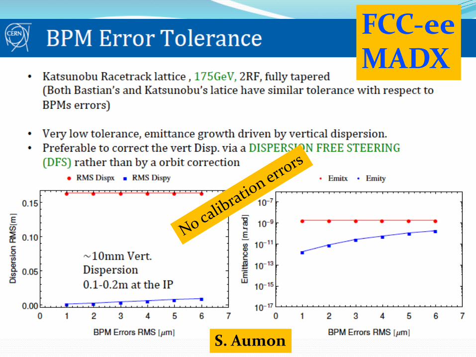
S. Aumon

FCC-eeMADX
S. Aumon
20µ quads misalignmentAll quads at same timeNo sextupolemisalignment
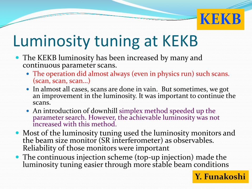
LuminositytuningatKEKB� The KEKB luminosity has been increased by many and
continuous parameter scans.� The operation did almost always (even in physics run) such scans.
(scan, scan, scan…)� In almost all cases, scans are done in vain. But sometimes, we got
an improvement in the luminosity. It was important to continue the scans.
� An introduction of downhill simplex method speeded up the parameter search. However, the achievable luminosity was not increased with this method.
� Most of the luminosity tuning used the luminosity monitors and the beam size monitor (SR interferometer) as observables. Reliability of those monitors were important
� The continuous injection scheme (top-up injection) made the luminosity tuning easier through more stable beam conditions
Y. Funakoshi
KEKB

TuningknobsforluminosityatKEKB
� A method of parameter search based on downhill simplex method was developed in 2007, which can search 12 parameters simultaneously. The speed of the luminosity tuning became faster. However, with this method the achievable luminosity was not improved.
chromaticityofx-ycouplingatIP Landsy attheSRM ~3days
Y. Funakoshi
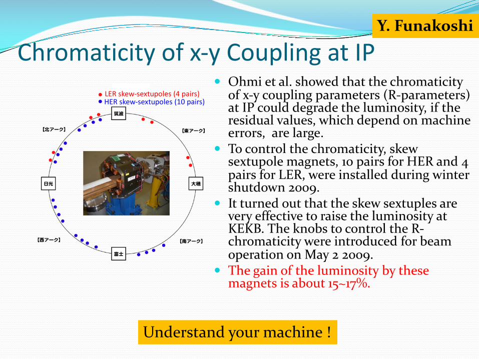
Chromaticityofx-yCouplingatIPLERskew-sextupoles(4pairs)HERskew-sextupoles(10pairs)
� Ohmi et al. showed that the chromaticity of x-y coupling parameters (R-parameters) at IP could degrade the luminosity, if the residual values, which depend on machine errors, are large.
� To control the chromaticity, skew sextupole magnets, 10 pairs for HER and 4 pairs for LER, were installed during winter shutdown 2009.
� It turned out that the skew sextuples are very effective to raise the luminosity at KEKB. The knobs to control the R-chromaticity were introduced for beam operation on May 2 2009.
� The gain of the luminosity by these magnets is about 15~17%.
Y. Funakoshi
Understand your machine !

Comments(1)� Turn-by-turn BPMs are needed for optimum measurement and
correction of CO and b-beating� BPMs errors (both misalignment and calibration) must be
included � Perform a separate analysis of Arcs Quads errors from FF
Quads, which affect much more performances due to high gradient/fringing fields
� Include detector solenoid (and anti-solenoids) in FF lattice to perform a real coupling minimization
� Knowledge of the real machine is important to be able to reproduce measured effects (ex. Lambertson septum in SuperKEKB) and correct them
� Separate power supplies (shunts) in quads are helpful for adjustments/measurements à b measurements, energy saw-tooth tapering
Comments(2)� Simulation of emittance tuning is a long process à pick
only one baseline lattice !� Use of MADX probably not optimal à check other codes
(SAD, AT with Matlab) à SL Sources experience � Colliders have strong FF doublets which are main
contribution to emittance growth by errors (not in SLS !)� Is 25 µ a realistic tolerance? What happens to luminosity
if design vertical emittance is not met? Can we “push” other parameters? à backup strategy
� b-beat correction is as important as emittance for a collider à luminosity depends on by* and zero hx,v*
� BUT… error correction is not ALL !
Comments(3)� Luminosity tuning is essential for optimizing
performances BUT is a long and tedious process � Multi-parameters knobs are useful (see KEKB
experience)� Knowledge of the real lattice is crucial à have a very
good MODEL � Understanding physical phenomena in your machine
is the key to success (ex. SuperKEKB)� This is a difficult but not impossible work… (see B-
Factories records!)
Keep going and improving!