Embed Size (px)
Citation preview
MV capacitors banks and accessories
Power factor correction and harmonic filtering
الکتروهمند
www.electrohamand.com
R8/9-2
MV capacitors banks and accessories
Introduction · · · · · · · · · · · · · · · · · · · · · · · · · · · · · · · · · · · · · · · · · · · · · · · · · · · · · · · · · · · · · · · · · · · · · · · · · · · · · · · · · · · · · · · · ·R8/9- 3
R.8 - MV capacitors and accessories
CHV-M Single-phase capacitor (indoor and outdoor use) · · · · · · · · · · · · · · · · · · · · · · · · · · · · · · · · · · · · · · · · · · · · · · · · · · · · · · · · · · · · · · · · R8-13
CHV-TThree-phase capacitor (Indoor use, with fuses and discharge resistor, internal) · · · · · · · · · · · · · · · · · · · · · · · · · · · · · · · · · · · · · · · · R8-17
LVC Three-phase contactor for MV capacitors. · · · · · · · · · · · · · · · · · · · · · · · · · · · · · · · · · · · · · · · · · · · · · · · · · · · · · · · · · · · · · · · · · · · · ·R8-19
RMV Choke reactor for capacitor banks · · · · · · · · · · · · · · · · · · · · · · · · · · · · · · · · · · · · · · · · · · · · · · · · · · · · · · · · · · · · · · · · · · · · · · · · · · · ·R8-20
R.9 - MV Capacitor banks
CIRKAP-C Fixed or automatic capacitor banks in cabinet · · · · · · · · · · · · · · · · · · · · · · · · · · · · · · · · · · · · · · · · · · · · · · · · · · · · · · · · · · · · · · · · · · ·R9-22
CIRKAP-GP High-powered capacitor banks in cabinet · · · · · · · · · · · · · · · · · · · · · · · · · · · · · · · · · · · · · · · · · · · · · · · · · · · · · · · · · · · · · · · · · · · · · ·R9-25
CIRKAP-CMFR / CMAR Fixed or automatic capacitor banks in cabinet with detuned filters · · · · · · · · · · · · · · · · · · · · · · · · · · · · · · · · · · · · · · · · · · · · · · · · · · ·R9-25
CIRKAP-B Capacitor banks in frames · · · · · · · · · · · · · · · · · · · · · · · · · · · · · · · · · · · · · · · · · · · · · · · · · · · · · · · · · · · · · · · · · · · · · · · · · · · · · · · · · ·R9-26
R8/9-3
Power factor correction and harmonic filtering
Medium Voltage Power Factor correction
R.8/9MV Power factor correction is directly related to the different aspects that as-sist the technical management of trans-port and distribution networks. These are:
Power quality. This involves the in-crease in the levels of voltage in substa-tion busbars and line ends.
Optimisation of the installation's cost of operation. In other words, the decrease of the reactive energy and, therefore, the reduction of apparent power entail two aspects of a strong technical relevance:
y Reduction of losses y Increase in the performance of trans-
formers and installations
Reduction of the economic cost of energy.
An in-depth description of each point is provided in the following sections.
Supply quality, voltage level
There are two cases: control of volt-age in MV substation busbars and line ends.
Control of voltage in substation bus-bars
One of the critical points in the distribu-tion of electrical energy is maintaining voltage in line ends. Distribution com-panies usually maintain the MV levels above its nominal value.
Therefore, MV capacitor banks are used. In fact, the connection of capaci-tor banks has an associated increase in voltage in the connection points.
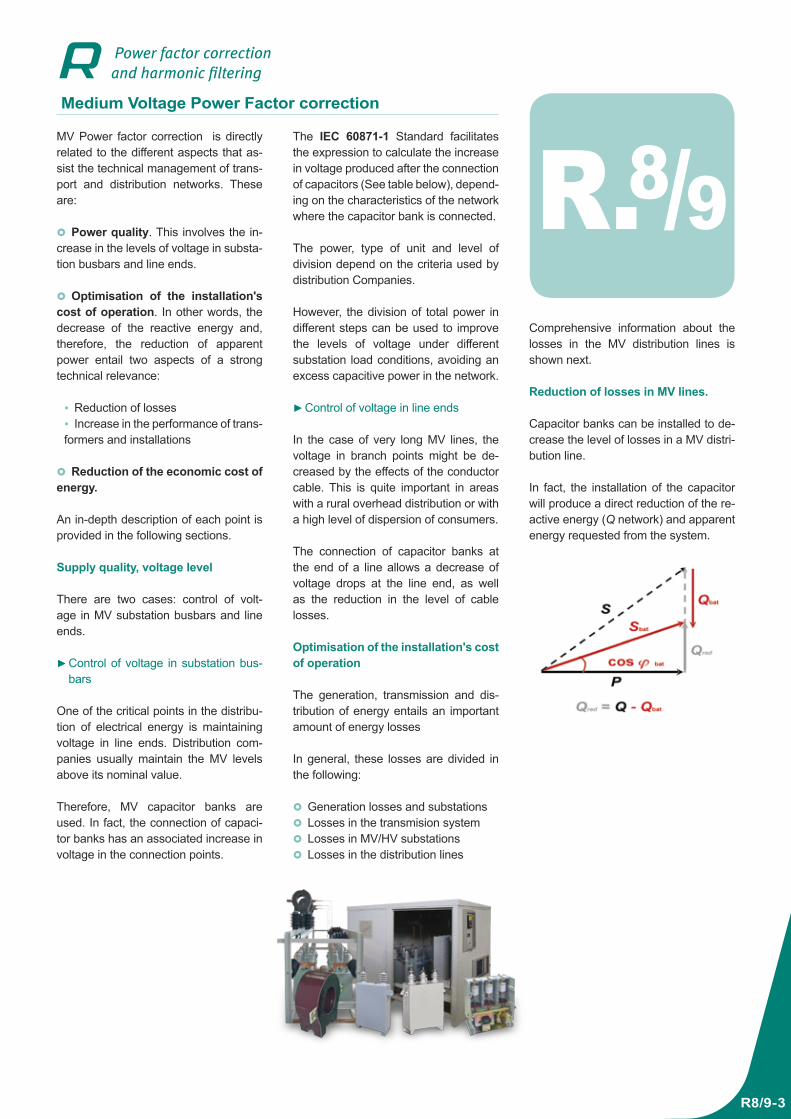
Comprehensive information about the losses in the MV distribution lines is shown next.
Reduction of losses in MV lines.
Capacitor banks can be installed to de-crease the level of losses in a MV distri-bution line.
In fact, the installation of the capacitor will produce a direct reduction of the re-active energy (Q network) and apparent energy requested from the system.
The IEC 60871-1 Standard facilitates the expression to calculate the increase in voltage produced after the connection of capacitors (See table below), depend-ing on the characteristics of the network where the capacitor bank is connected.
The power, type of unit and level of division depend on the criteria used by distribution Companies.
However, the division of total power in different steps can be used to improve the levels of voltage under different substation load conditions, avoiding an excess capacitive power in the network.
Control of voltage in line ends
In the case of very long MV lines, the voltage in branch points might be de-creased by the effects of the conductor cable. This is quite important in areas with a rural overhead distribution or with a high level of dispersion of consumers.
The connection of capacitor banks at the end of a line allows a decrease of voltage drops at the line end, as well as the reduction in the level of cable losses.
Optimisation of the installation's cost of operation
The generation, transmission and dis-tribution of energy entails an important amount of energy losses
In general, these losses are divided in the following:
Generation losses and substations Losses in the transmision system Losses in MV/HV substations Losses in the distribution lines
MV capacitors banks and accessories
R8/9-4
Units used to understand the calculation expressions:
P active power transmitted by the line in kW
Q reactive energy absorbed without capacitor banks
Qbank power of the capacitor bank in MV ·A
I current
U Network voltage in kV
R1 resistance of the cable in Ω/km
X1 reactor of the cable in Ω/km
L length of the line in km
SCC short-circuit power in the connection point in MV ·A.
This point is important when making the economic assessment of the performance of an installation, since there is an added “hidden cost” to the payment for reactive energy consumption, which is represented by the active energy dissipated during distribution.
Line and cable discharge
The decrease in apparent power after the connection of a capacitor bank en-tails two immediate consequences:
Decrease of the load transmitted through cables
Increase of the supply capacity of transformers
Increase of the voltage at the end of the line
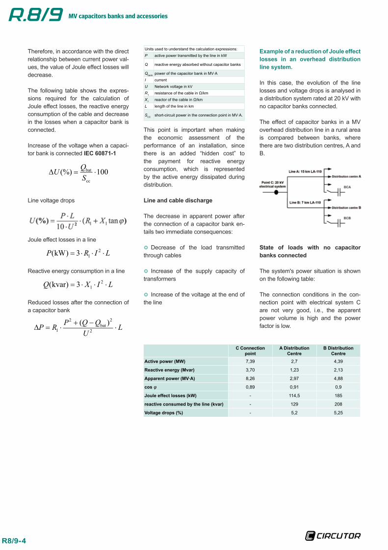
Example of a reduction of Joule effect losses in an overhead distribution line system.
In this case, the evolution of the line losses and voltage drops is analysed in a distribution system rated at 20 kV with no capacitor banks connected.
The effect of capacitor banks in a MV overhead distribution line in a rural area is compared between banks, where there are two distribution centres, A and B.
State of loads with no capacitor banks connected
The system's power situation is shown on the following table:
The connection conditions in the con-nection point with electrical system C are not very good, i.e., the apparent power volume is high and the power factor is low.
C Connection point
A Distribution Centre
B Distribution Centre
Active power (MW) 7,39 2,7 4,39
Reactive energy (Mvar) 3,70 1,23 2,13
Apparent power (MV·A) 8,26 2,97 4,88
cos φ 0,89 0,91 0,9
Joule effect losses (kW) - 114,5 185
reactive consumed by the line (kvar) - 129 208
Voltage drops (%) - 5,2 5,25
Therefore, in accordance with the direct relationship between current power val-ues, the value of Joule effect losses will decrease.
The following table shows the expres-sions required for the calculation of Joule effect losses, the reactive energy consumption of the cable and decrease in the losses when a capacitor bank is connected.
Increase of the voltage when a capaci-tor bank is connected IEC 60871-1
Line voltage drops
Joule effect losses in a line
Reactive energy consumption in a line
Reduced losses after the connection of a capacitor bank
MV capacitors banks and accessories
R8/9-5
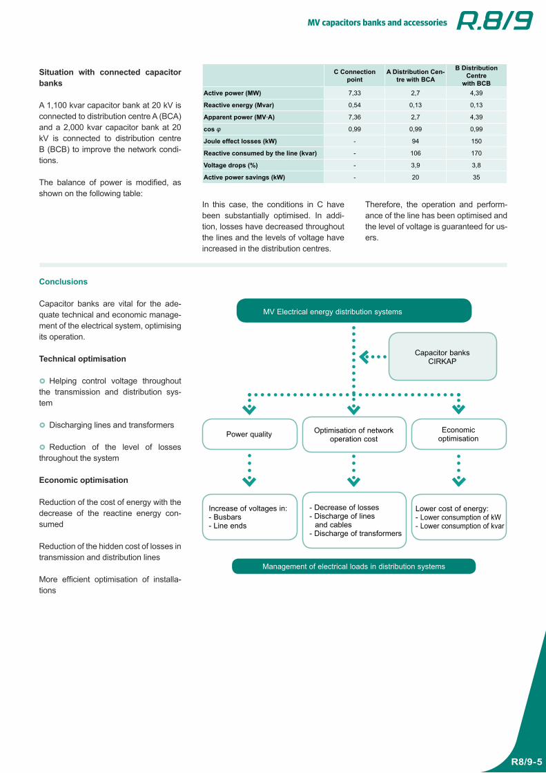
Situation with connected capacitor banks
A 1,100 kvar capacitor bank at 20 kV is connected to distribution centre A (BCA) and a 2,000 kvar capacitor bank at 20 kV is connected to distribution centre B (BCB) to improve the network condi-tions.
The balance of power is modified, as shown on the following table:
Conclusions
Capacitor banks are vital for the ade-quate technical and economic manage-ment of the electrical system, optimising its operation.
Technical optimisation
Helping control voltage throughout the transmission and distribution sys-tem
Discharging lines and transformers
Reduction of the level of losses throughout the system
Economic optimisation
Reduction of the cost of energy with the decrease of the reactine energy con-sumed
Reduction of the hidden cost of losses in transmission and distribution lines
More efficient optimisation of installa-tions
In this case, the conditions in C have been substantially optimised. In addi-tion, losses have decreased throughout the lines and the levels of voltage have increased in the distribution centres.
Therefore, the operation and perform-ance of the line has been optimised and the level of voltage is guaranteed for us-ers.
C Connection point
A Distribution Cen-tre with BCA
B Distribution Centre
with BCBActive power (MW) 7,33 2,7 4,39
Reactive energy (Mvar) 0,54 0,13 0,13
Apparent power (MV·A) 7,36 2,7 4,39
cos φ 0,99 0,99 0,99
Joule effect losses (kW) - 94 150
Reactive consumed by the line (kvar) - 106 170
Voltage drops (%) - 3,9 3,8
Active power savings (kW) - 20 35
MV Electrical energy distribution systems
Power quality Optimisation of network operation cost
Capacitor banksCIRKAP
Management of electrical loads in distribution systems
Economicoptimisation
Increase of voltages in:- Busbars- Line ends
- Decrease of losses- Discharge of lines
and cables- Discharge of transformers
Lower cost of energy:- Lower consumption of kW- Lower consumption of kvar
MV capacitors banks and accessories
R8/9-6
Where to compensate in MV
Electrical energy generation, transmis-sion and distribution
Reactive energy transmission and distri-bution throughout the electrical system is noteworthy, as stated above. Therefore, the reactive energy must be compensat-ed in determined points of the electrical network. These are:
Generation stations: Such as low-powered hydroelectric power plants and wind farms Receiving / distribution substations.
(for example, reception 400 kV, distribu-tion at 20 kV) Distribution centres
Industrial installations with MV distri-bution and consumption
In general, the installations that distrib-ute and consume MV are likely to be compensated.
For example:
Pumping stations Mining Industry: cement, chemical, steel,
etc.
There are transformers, asynchronous motors or electric arc equipment in all of these industries, which are large reac-tive energy consumers.
MV distribution and LV consuming installations
In MV receiving installations with a distri-bution and consumption of LV, the com-pensation must always be carried out in Low Voltage. The reasons are:
Low power is cheaper in LV More accurate regulation
However, when there is a high number of LV / MV transformers, we recommend the installation of LV regulated capacitor banks and a fixed MV section.
Components for MV capacitor banks
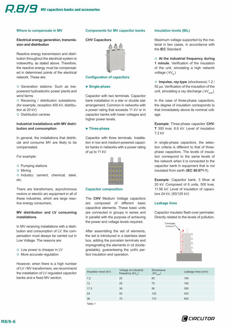
CHV Capacitors
Configuration of capacitors
Single-phase
Capacitor with two terminals. Capacitor bank installation in a star or double star arrangement. Common in networks with a power rating that exceeds 11 kV or in capacitor banks with lower voltages and higher power levels.
Three-phase
Capacitor with three terminals. Installa-tion in low and medium-powered capaci-tor banks in networks with a power rating of up to 11 kV.
Capacitor composition
The CHV Medium Voltage capacitors are composed of different basic capacitive elements. These basic units are connected in groups in series and in parallel with the purpose of achieving the power and voltage levels required.
After assembling the set of elements, the set is introduced in a stainless steel box, adding the porcelain terminals and impregnating the elements in oil (biode-gradable), guaranteeing the unit's per-fect insulation and operation.
Insulation levels (BIL)
Maximum voltage supported by the ma-terial in two cases, in accordance with the IEC Standard:
At the industrial frequency during 1 minute. Verification of the insulation of the unit, simulating a high network voltage ( kVef.)
Impulse, ray-type (shockwave) 1.2 / 50 µs. Verification of the insulation of the unit, simulating a ray discharge ( kVpeak)
In the case of three-phase capacitors, the degree of insulation corresponds to that immediately above its nominal volt-age.
Example: Three-phase capacitor CHV-T 300 kvar, 6.6 kV. Level of insulation 7.2 kV
In single-phase capacitors, the selec-tion criteria is different to that of three-phase capacitors. The levels of insula-tion correspond to the same levels of the network when it is connected to the capacitor bank in equipment that is not insulated from earth (IEC 60.671-1).
Example: Capacitor bank, 3 Mvar at 20 kV. Composed of 6 units, 500 kvar, 11.56 kV. Level of insulation of capaci-tors 24 kV, (50/125 kV)
Leakage lines
Capacitor insulator flash-over perimeter. Directly related to the levels of pollution.
Insulation level (kV) Voltage at industrial frequency (kVef.)
Shockwave (kVpeak)
Leakage lines (mm)
7,2 20 60 190
12 28 75 190
17,5 38 95 300
24 50 125 435
36 70 170 600
Table 1
MV capacitors banks and accessories
R8/9-7
Pollution levels
The pollution level defines the environ-mental contamination existing in the place where equipment is installed. Therefore, to avoid insulation defects as a consequence of flash-over, the greater the degree of environmental pollution, the greater the leakage of insulators.
It is expressed in mm / kV. In other words, the relationship between the in-sulator leakage line and network volt-age. The pollution levels defined are shown on the following table:
Classification Pollution level
Low 16 mm/kV
Medium 20 mm/kV
High 25 mm/kV
Very high 31 mm/kV
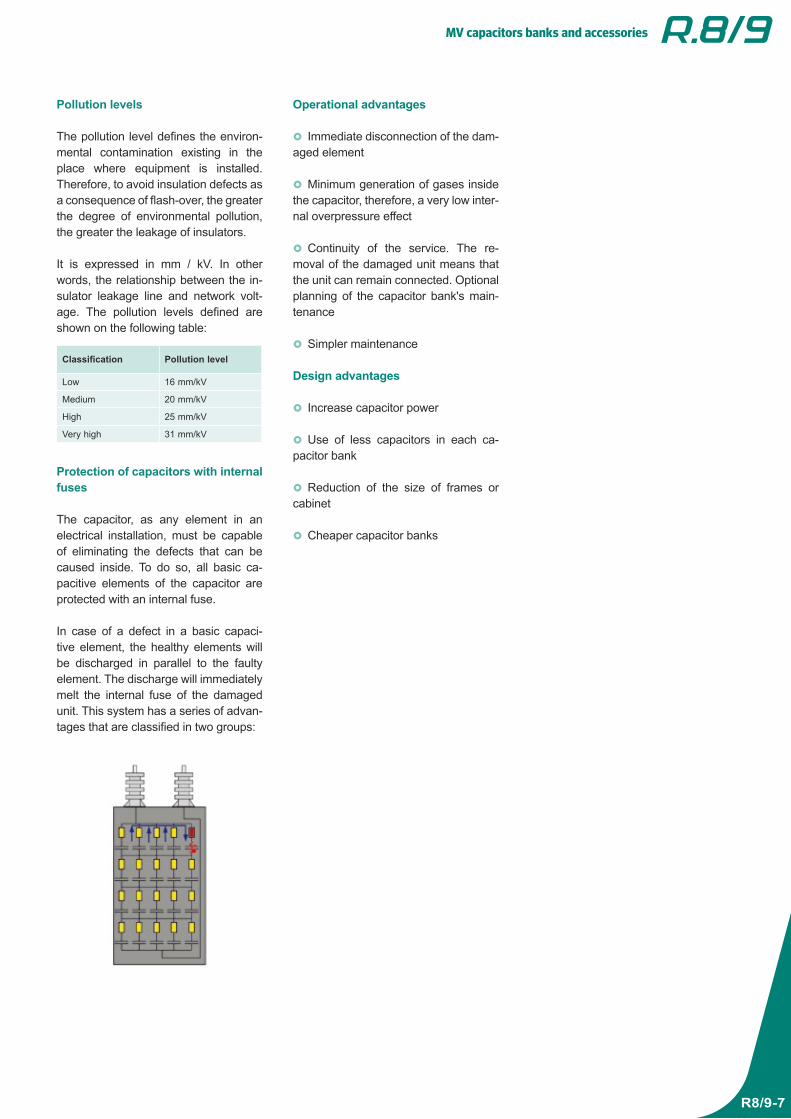
Protection of capacitors with internal fuses
The capacitor, as any element in an electrical installation, must be capable of eliminating the defects that can be caused inside. To do so, all basic ca-pacitive elements of the capacitor are protected with an internal fuse.
In case of a defect in a basic capaci-tive element, the healthy elements will be discharged in parallel to the faulty element. The discharge will immediately melt the internal fuse of the damaged unit. This system has a series of advan-tages that are classified in two groups:
Operational advantages
Immediate disconnection of the dam-aged element
Minimum generation of gases inside the capacitor, therefore, a very low inter-nal overpressure effect
Continuity of the service. The re-moval of the damaged unit means that the unit can remain connected. Optional planning of the capacitor bank's main-tenance
Simpler maintenance
Design advantages
Increase capacitor power
Use of less capacitors in each ca-pacitor bank
Reduction of the size of frames or cabinet
Cheaper capacitor banks
MV capacitors banks and accessories
R8/9-8
MV Capacitor banks
Configuration of capacitor banks
The use of different configurations is common in MV capacitor banks. These depend on the type of capacitor used and, above all, on the installation's elec-trical parameters.
Capacitor banks, three-phase capaci-tors
These units are useful in industrial in-stallations, since they are capable of hosting low and medium-powered ap-plications in small dimensions.
The maximum service voltage is 11 kV and the maximum power is 1.4 Mvar.
The most common applications are:
Compensation of motors Compensation of transformers Automatic capacitor banks
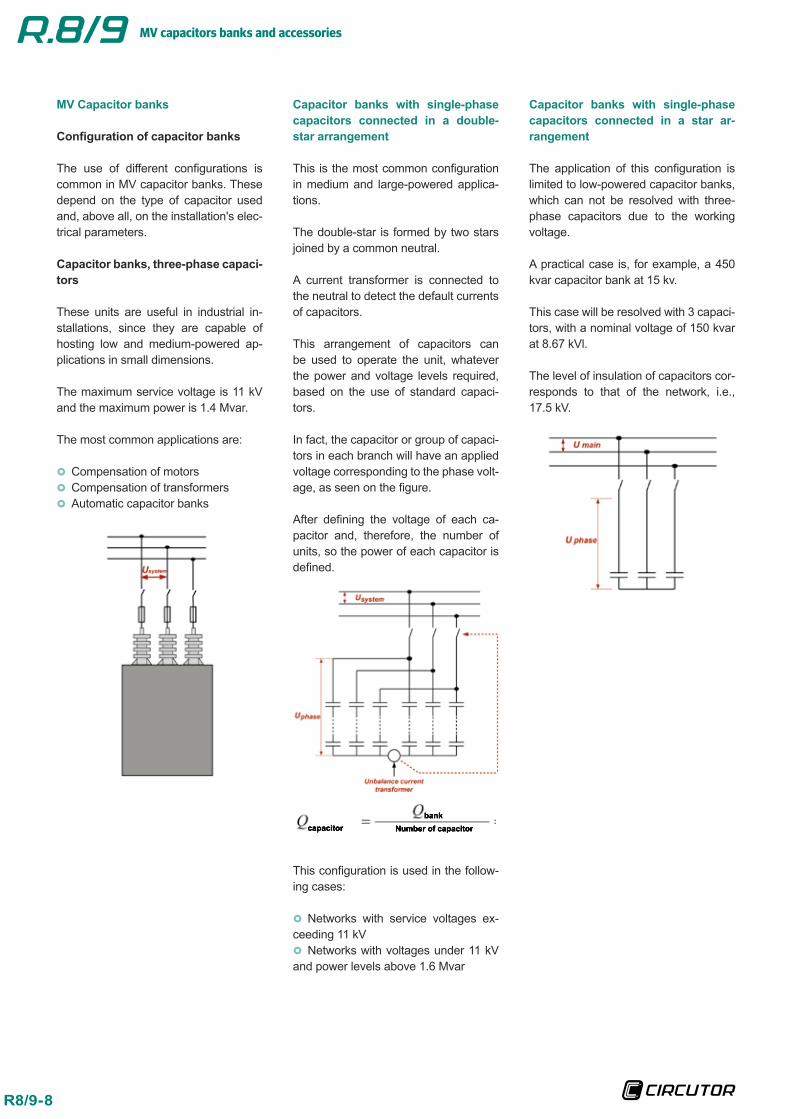
Capacitor banks with single-phase capacitors connected in a double-star arrangement
This is the most common configuration in medium and large-powered applica-tions.
The double-star is formed by two stars joined by a common neutral.
A current transformer is connected to the neutral to detect the default currents of capacitors.
This arrangement of capacitors can be used to operate the unit, whatever the power and voltage levels required, based on the use of standard capaci-tors.
In fact, the capacitor or group of capaci-tors in each branch will have an applied voltage corresponding to the phase volt-age, as seen on the figure.
After defining the voltage of each ca-pacitor and, therefore, the number of units, so the power of each capacitor is defined.
This configuration is used in the follow-ing cases:
Networks with service voltages ex-ceeding 11 kV Networks with voltages under 11 kV
and power levels above 1.6 Mvar
Capacitor banks with single-phase capacitors connected in a star ar-rangement
The application of this configuration is limited to low-powered capacitor banks, which can not be resolved with three-phase capacitors due to the working voltage.
A practical case is, for example, a 450 kvar capacitor bank at 15 kv.
This case will be resolved with 3 capaci-tors, with a nominal voltage of 150 kvar at 8.67 kVl.
The level of insulation of capacitors cor-responds to that of the network, i.e., 17.5 kV.
MV capacitors banks and accessories
R8/9-9
Protection of capacitor banks
In general, capacitor bank protection systems are divided in external and in-ternal protections.
Internal protection
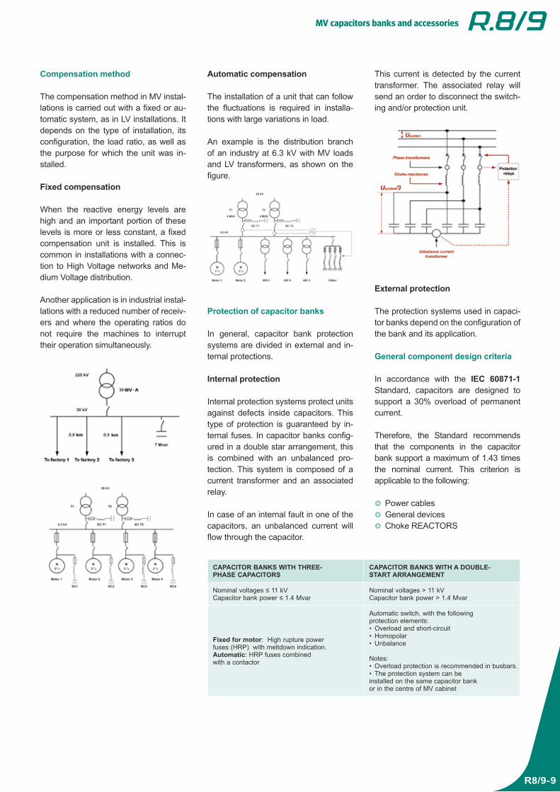
Internal protection systems protect units against defects inside capacitors. This type of protection is guaranteed by in-ternal fuses. In capacitor banks config-ured in a double star arrangement, this is combined with an unbalanced pro-tection. This system is composed of a current transformer and an associated relay.
In case of an internal fault in one of the capacitors, an unbalanced current will flow through the capacitor.
CAPACITOR BANKS WITH THREE-PHASE CAPACITORS
CAPACITOR BANKS WITH A DOUBLE-START ARRANGEMENT
Nominal voltages ≤ 11 kVCapacitor bank power ≤ 1.4 Mvar
Nominal voltages > 11 kVCapacitor bank power > 1.4 Mvar
Fixed for motor: High rupture power fuses (HRP) with meltdown indication.Automatic: HRP fuses combined with a contactor
Automatic switch, with the following protection elements: • Overload and short-circuit • Homopolar • Unbalance
Notes: • Overload protection is recommended in busbars. • The protection system can be
installed on the same capacitor bank or in the centre of MV cabinet
Compensation method
The compensation method in MV instal-lations is carried out with a fixed or au-tomatic system, as in LV installations. It depends on the type of installation, its configuration, the load ratio, as well as the purpose for which the unit was in-stalled.
Fixed compensation
When the reactive energy levels are high and an important portion of these levels is more or less constant, a fixed compensation unit is installed. This is common in installations with a connec-tion to High Voltage networks and Me-dium Voltage distribution.
Another application is in industrial instal-lations with a reduced number of receiv-ers and where the operating ratios do not require the machines to interrupt their operation simultaneously.
Automatic compensation
The installation of a unit that can follow the fluctuations is required in installa-tions with large variations in load.
An example is the distribution branch of an industry at 6.3 kV with MV loads and LV transformers, as shown on the figure.
This current is detected by the current transformer. The associated relay will send an order to disconnect the switch-ing and/or protection unit.
External protection
The protection systems used in capaci-tor banks depend on the configuration of the bank and its application.
General component design criteria
In accordance with the IEC 60871-1 Standard, capacitors are designed to support a 30% overload of permanent current.
Therefore, the Standard recommends that the components in the capacitor bank support a maximum of 1.43 times the nominal current. This criterion is applicable to the following:
Power cables General devices Choke REACTORS
MV capacitors banks and accessories
R8/9-10
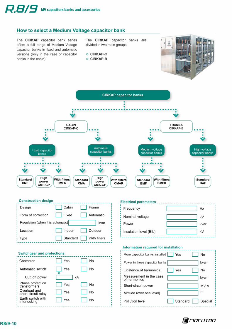
CIRKAP capacitor banks
CABINCIRKAP-C
FRAMESCIRKAP-B
Automatic capacitor banks
High-voltage capacitor banks
Medium voltage capacitor banks
Fixed capacitor banks
With filtersBMFR
StandardBMF
StandardBAF
With filtersCMAR
StandardCMA
High power
CMA-GP
With filtersCMFR
StandardCMF
High power
CMF-GP
How to select a Medium Voltage capacitor bank
The CIRKAP capacitor bank series offers a full range of Medium Voltage capacitor banks in fixed and automatic versions (only in the case of capacitor banks in the cabin).
Electrical parametersConstruction design
Information required for installation
More capacitor banks installed
Existence of harmonics
Pollution level Standard Special
Altitude (over sea level) m
Measurement in the case of harmonics kvar
Yes No
Yes No
Power in these capacitor banks kvar
Short-circuit power MV ·A
Switchgear and protections
Power kvar
Insulation level (BIL) kV
Nominal voltage kV
Frequency Hz
Location
Form of correction
Type
Design
Regulation (when it is automatic)
Cabin Frame
kvar
Standard With filters
Fixed Automatic
Indoor Outdoor
Contactor
Automatic switch
Phase protection transformersOverload and short-circuit relayEarth switch with interlocking
Cutt off power
Yes No
Yes No
Yes No
Yes No
Yes No
kA
The CIRKAP capacitor banks are divided in two main groups:
CIRKAP-C CIRKAP-B
MV capacitors banks and accessories
R8/9-11
GENERAL BASIC INFORMATION
INST
ALL
ATIO
N
• Network voltage (kV) • Network frequency (Hz) • Short-circuit power MV ·A • Existence of more capacitor banks (Yes/No)
• Existence of harmonics (Yes/No)
1
CA
PAC
ITO
R B
AN
K • Power of the capacitor bank (kvar) • Capacitor bank voltage (kV) • Fixed / automatic • Type: standard or with filters • General protection requirement (Yes/No)
• Location: indoor or outdoor • Other special needs
2
DEFINITION OF COMPONENTS
CA
PAC
ITO
RS • Configuration, single or three-phase
• Nominal voltage (kV) • Frequency (Hz) • Insulation level (kV) • Reactive power (kvar) • Special leakage line (mm/kV)
REA
CTO
RS
• Quantity (3 per capacitor bank or step) • Inductance (µH) • Current (A) • Level of insulation (kV) • Short-duration current (kA/1s) • Location: indoor or outdoor
SWIT
CH
GEA
R For automatic capacitor banks • Contactor U < 12 kV • Switch U > 12 kV • Capacitive power to cut off(kvar) • Insulation level (kV) • Switch cut off power (kA)
7
DEFINITION OF THE CAPACITOR BANK
CO
NFI
GU
RAT
ION When U > 11.5 kV and Q < 1 400 kvar
•Capacitor bank, three-phase capacitors
When U > 11.5 and Q < 1 400 kvar orWhen U < 11.5 and Q > 1 400 kvar •Double-star capacitor bank, single-phase capacitors
3
DES
IGN
Fixed: • CMF • BMF
Automatic: • CMA • Number and power of steps
4
Equipment and component definition guide
Calculation example
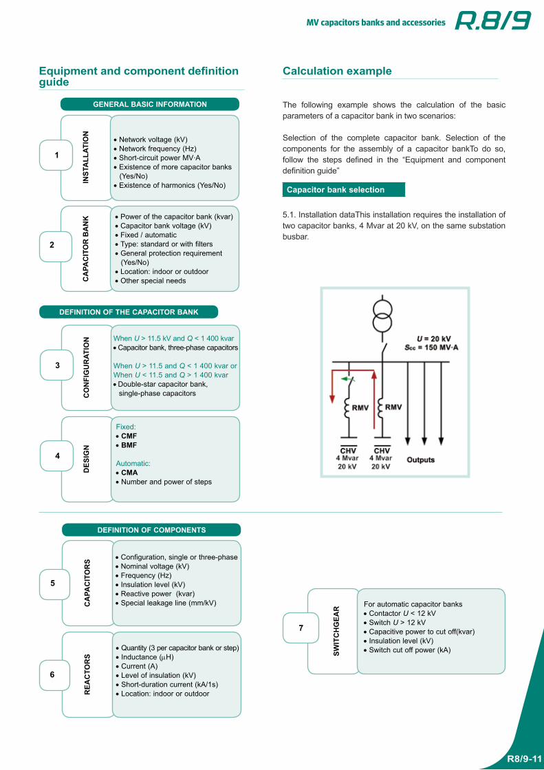
The following example shows the calculation of the basic parameters of a capacitor bank in two scenarios:
Selection of the complete capacitor bank. Selection of the components for the assembly of a capacitor bankTo do so, follow the steps defined in the “Equipment and component definition guide”
Capacitor bank selection
5.1. Installation dataThis installation requires the installation of two capacitor banks, 4 Mvar at 20 kV, on the same substation busbar.
5
6
MV capacitors banks and accessories
R8/9-12R8/9-12
GENERAL BASIC INFORMATIONIN
STA
LLAT
ION
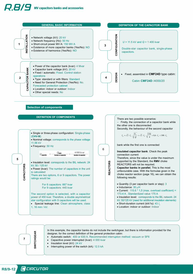
• Network voltage (kV): 20 kV • Network frequency (Hz): 50 Hz • Short-circuit power MV ·A: 150 MV ·A • Existence of more capacitor banks (Yes/No): NO • Existence of harmonics (Yes/No): NO
1
CA
PAC
ITO
R B
AN
K
• Power of the capacitor bank (kvar): 4 Mvar • Capacitor bank voltage (kV): 20 kV • Fixed / automatic: Fixed. Control station
operations • Type: standard or with filters: Standard • Need for General Protection (Yes/No): No.
Forecasted protection cabinet • Location: indoor or outdoor: Indoor • Other special needs: No
2
DEFINITION OF THE CAPACITOR BANK
CO
NFI
GU
RAT
ION
3
DES
IGN • Fixed, assembled in CMF24D type cabin:
Cabin CMF24D /4000/204
U > 11.5 kV and Q > 1 400 kvar
Double-star capacitor bank, single-phase capacitors.
Selection of components
DEFINITION OF COMPONENTS
CA
PAC
ITO
RS
• Single or three-phase configuration: Single-phase (CHV-M) • Nominal voltage: corresponds to the phase voltage
11.56 kV • Frequency: 50 Hz
• Insulation level: corresponds to the BIL network: 24 kV, 50 / 125 kV • Power (kvar): The number of capacitors in the unit
is calculatedThere are two options, 6 or 9 capacitors. The power ratings would be:
For 6 capacitors: 667 kvar For 9 capacitors: 445 kvar
The second option is selected, with a capacitor power of 450 kvar. Therefore, a double asymmetrical star configuration with 9 capacitors will be used. • Special leakage line: Clean atmosphere, class
1, 16 mm / kV.
5
REA
CTO
RS
There are two possible scenarios: − Firstly, the connection of a capacitor bank while
the other one is disconnectedSecondly, the behaviour of the second capacitor
bank while the first one is connected
Insulated capacitor bank. Check the peak connection currentTherefore, since the value is under the maximum supported by the Standard, the RMV choke REACTORS will not be required.Capacitor banks in parallel. This is the most unfavourable case. With the formulae given in the choke reactor section (page 16), we can obtain the following results:
• Quantity (3 per capacitor bank or step): 3 • Inductance: 30 µH • Current: 115.6 * 1,5 (max. overload coefficient) =
173.4 A . Standardized value 175 A • Insulation level: corresponds to the BIL network: 24
kV, 50/125 kV (need for additional insulation elements) • Short-duration current (kA/1s): 43 In • Location: indoor or outdoor: Indoor
6
SWIT
CH
GEA
R In this example, the capacitor banks do not include the switchgear, but there is information provided for the designer, for the correct definition of the general protection cabin: • Automatic switch: 400 or 630 A. Recommended interruption method: vacuum or SF6 • Capacitive power interrupted (kvar): 4 000 kvar • Insulation level (kV): 24 kV • Interrupting power of the switch (kA): 12.5 kA
7
MV capacitors and accessories
R8-13
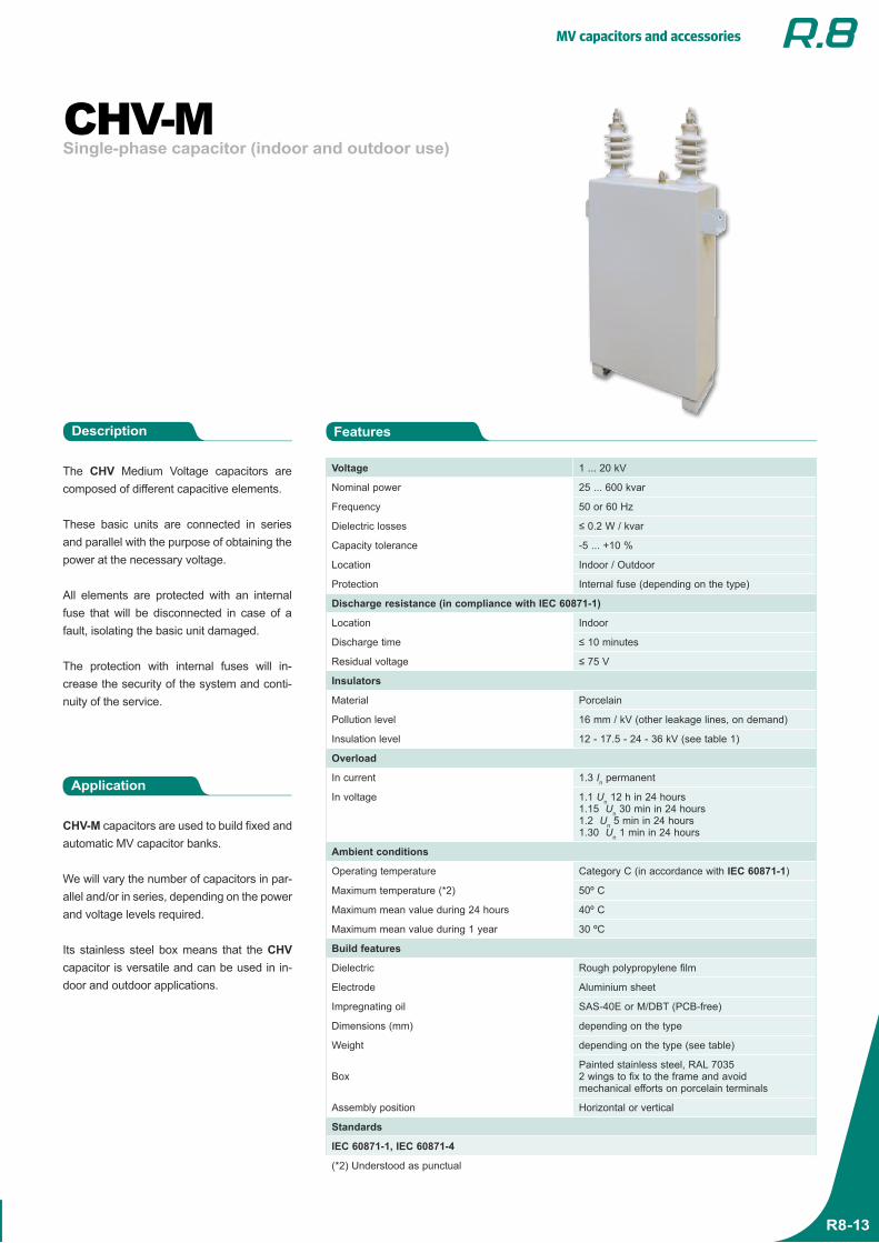
Single-phase capacitor (indoor and outdoor use)CHV-M
The CHV Medium Voltage capacitors are composed of different capacitive elements.
These basic units are connected in series and parallel with the purpose of obtaining the power at the necessary voltage.
All elements are protected with an internal fuse that will be disconnected in case of a fault, isolating the basic unit damaged.
The protection with internal fuses will in-crease the security of the system and conti-nuity of the service.
Application
CHV-M capacitors are used to build fixed and automatic MV capacitor banks.
We will vary the number of capacitors in par-allel and/or in series, depending on the power and voltage levels required.
Its stainless steel box means that the CHV capacitor is versatile and can be used in in-door and outdoor applications.
FeaturesDescription
Voltage 1 ... 20 kV
Nominal power 25 ... 600 kvar
Frequency 50 or 60 Hz
Dielectric losses ≤ 0.2 W / kvar
Capacity tolerance -5 ... +10 %
Location Indoor / Outdoor
Protection Internal fuse (depending on the type)
Discharge resistance (in compliance with IEC 60871-1)
Location Indoor
Discharge time ≤ 10 minutes
Residual voltage ≤ 75 V
Insulators
Material Porcelain
Pollution level 16 mm / kV (other leakage lines, on demand)
Insulation level 12 - 17.5 - 24 - 36 kV (see table 1)
Overload
In current 1.3 In permanent
In voltage 1.1 Un 12 h in 24 hours1.15 Un 30 min in 24 hours1.2 Un 5 min in 24 hours1.30 Un 1 min in 24 hours
Ambient conditions
Operating temperature Category C (in accordance with IEC 60871-1)
Maximum temperature (*2) 50º C
Maximum mean value during 24 hours 40º C
Maximum mean value during 1 year 30 ºC
Build features
Dielectric Rough polypropylene film
Electrode Aluminium sheet
Impregnating oil SAS-40E or M/DBT (PCB-free)
Dimensions (mm) depending on the type
Weight depending on the type (see table)
BoxPainted stainless steel, RAL 70352 wings to fix to the frame and avoid mechanical efforts on porcelain terminals
Assembly position Horizontal or vertical
Standards
IEC 60871-1, IEC 60871-4
(*2) Understood as punctual
MV capacitors and accessories
R8-14
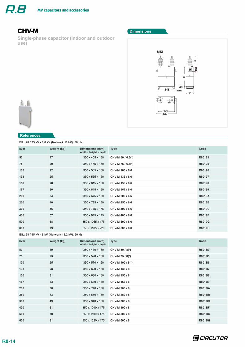
References
Dimensions
Single-phase capacitor (indoor and outdoor use)
CHV-M
BIL: 28 / 75 kV - 6.6 kV (Network 11 kV). 50 Hz
kvar Weight (kg) Dimensions (mm)width x height x depth
Type Code
50 17 350 x 405 x 160 CHV-M 50 / 6.6(*) R80193
75 20 350 x 455 x 160 CHV-M 75 / 6.6(*) R80195
100 22 350 x 505 x 160 CHV-M 100 / 6.6 R80196
133 25 350 x 565 x 160 CHV-M 133 / 6.6 R80197
150 28 350 x 615 x 160 CHV-M 150 / 6.6 R80198
167 30 350 x 615 x 160 CHV-M 167 / 6.6 R80199
200 34 350 x 675 x 160 CHV-M 200 / 6.6 R8019A
250 40 350 x 785 x 160 CHV-M 250 / 6.6 R8019B
300 46 350 x 775 x 175 CHV-M 300 / 6.6 R8019C
400 57 350 x 915 x 175 CHV-M 400 / 6.6 R8019F
500 68 350 x 1055 x 175 CHV-M 500 / 6.6 R8019G
600 79 350 x 1165 x 220 CHV-M 600 / 6.6 R8019H
BIL: 38 / 95 kV - 8 kV (Network 13.2 kV). 50 Hz
kvar Weight (kg) Dimensions (mm)width x height x depth
Type Code
50 19 350 x 470 x 160 CHV-M 50 / 8(*) R801B3
75 23 350 x 520 x 160 CHV-M 75 / 8(*) R801B5
100 25 350 x 570 x 160 CHV-M 100 / 8(*) R801B6
133 28 350 x 620 x 160 CHV-M 133 / 8 R801B7
150 31 350 x 680 x 160 CHV-M 150 / 8 R801B8
167 33 350 x 680 x 160 CHV-M 167 / 8 R801B9
200 38 350 x 740 x 160 CHV-M 200 / 8 R801BA
250 43 350 x 850 x 160 CHV-M 250 / 8 R801BB
300 49 350 x 940 x 160 CHV-M 300 / 8 R801BC
400 61 350 x 1010 x 175 CHV-M 400 / 8 R801BF
500 70 350 x 1190 x 175 CHV-M 500 / 8 R801BG
600 81 350 x 1230 x 175 CHV-M 600 / 8 R801BH
MV capacitors and accessories
R8-15
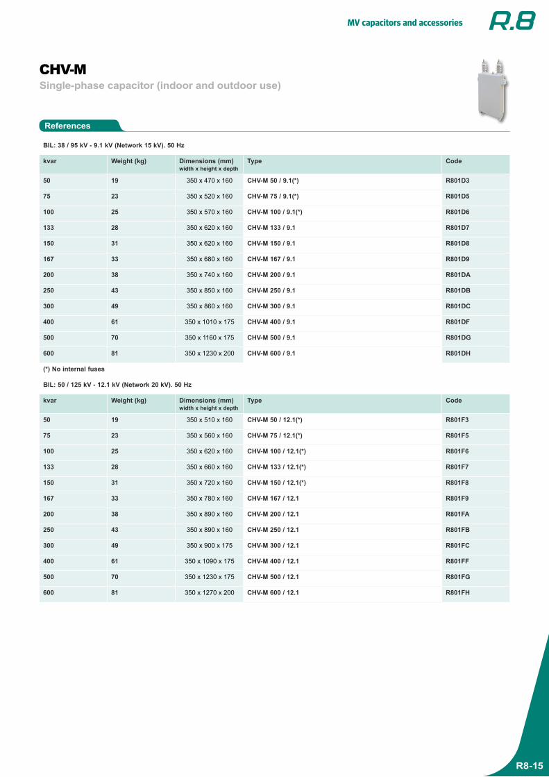
References
Single-phase capacitor (indoor and outdoor use)CHV-M
BIL: 38 / 95 kV - 9.1 kV (Network 15 kV). 50 Hz
kvar Weight (kg) Dimensions (mm)width x height x depth
Type Code
50 19 350 x 470 x 160 CHV-M 50 / 9.1(*) R801D3
75 23 350 x 520 x 160 CHV-M 75 / 9.1(*) R801D5
100 25 350 x 570 x 160 CHV-M 100 / 9.1(*) R801D6
133 28 350 x 620 x 160 CHV-M 133 / 9.1 R801D7
150 31 350 x 620 x 160 CHV-M 150 / 9.1 R801D8
167 33 350 x 680 x 160 CHV-M 167 / 9.1 R801D9
200 38 350 x 740 x 160 CHV-M 200 / 9.1 R801DA
250 43 350 x 850 x 160 CHV-M 250 / 9.1 R801DB
300 49 350 x 860 x 160 CHV-M 300 / 9.1 R801DC
400 61 350 x 1010 x 175 CHV-M 400 / 9.1 R801DF
500 70 350 x 1160 x 175 CHV-M 500 / 9.1 R801DG
600 81 350 x 1230 x 200 CHV-M 600 / 9.1 R801DH
(*) No internal fuses
BIL: 50 / 125 kV - 12.1 kV (Network 20 kV). 50 Hz
kvar Weight (kg) Dimensions (mm)width x height x depth
Type Code
50 19 350 x 510 x 160 CHV-M 50 / 12.1(*) R801F3
75 23 350 x 560 x 160 CHV-M 75 / 12.1(*) R801F5
100 25 350 x 620 x 160 CHV-M 100 / 12.1(*) R801F6
133 28 350 x 660 x 160 CHV-M 133 / 12.1(*) R801F7
150 31 350 x 720 x 160 CHV-M 150 / 12.1(*) R801F8
167 33 350 x 780 x 160 CHV-M 167 / 12.1 R801F9
200 38 350 x 890 x 160 CHV-M 200 / 12.1 R801FA
250 43 350 x 890 x 160 CHV-M 250 / 12.1 R801FB
300 49 350 x 900 x 175 CHV-M 300 / 12.1 R801FC
400 61 350 x 1090 x 175 CHV-M 400 / 12.1 R801FF
500 70 350 x 1230 x 175 CHV-M 500 / 12.1 R801FG
600 81 350 x 1270 x 200 CHV-M 600 / 12.1 R801FH
MV capacitors and accessories
R8-16
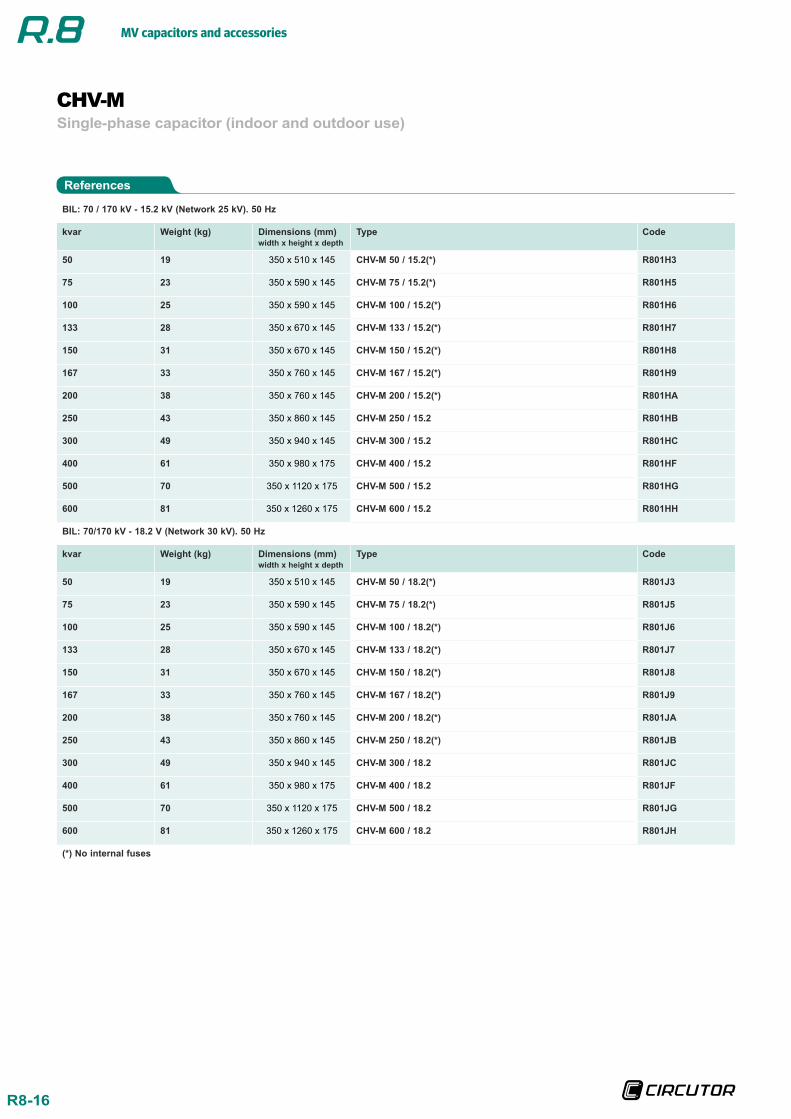
BIL: 70 / 170 kV - 15.2 kV (Network 25 kV). 50 Hz
kvar Weight (kg) Dimensions (mm)width x height x depth
Type Code
50 19 350 x 510 x 145 CHV-M 50 / 15.2(*) R801H3
75 23 350 x 590 x 145 CHV-M 75 / 15.2(*) R801H5
100 25 350 x 590 x 145 CHV-M 100 / 15.2(*) R801H6
133 28 350 x 670 x 145 CHV-M 133 / 15.2(*) R801H7
150 31 350 x 670 x 145 CHV-M 150 / 15.2(*) R801H8
167 33 350 x 760 x 145 CHV-M 167 / 15.2(*) R801H9
200 38 350 x 760 x 145 CHV-M 200 / 15.2(*) R801HA
250 43 350 x 860 x 145 CHV-M 250 / 15.2 R801HB
300 49 350 x 940 x 145 CHV-M 300 / 15.2 R801HC
400 61 350 x 980 x 175 CHV-M 400 / 15.2 R801HF
500 70 350 x 1120 x 175 CHV-M 500 / 15.2 R801HG
600 81 350 x 1260 x 175 CHV-M 600 / 15.2 R801HH
BIL: 70/170 kV - 18.2 V (Network 30 kV). 50 Hz
kvar Weight (kg) Dimensions (mm)width x height x depth
Type Code
50 19 350 x 510 x 145 CHV-M 50 / 18.2(*) R801J3
75 23 350 x 590 x 145 CHV-M 75 / 18.2(*) R801J5
100 25 350 x 590 x 145 CHV-M 100 / 18.2(*) R801J6
133 28 350 x 670 x 145 CHV-M 133 / 18.2(*) R801J7
150 31 350 x 670 x 145 CHV-M 150 / 18.2(*) R801J8
167 33 350 x 760 x 145 CHV-M 167 / 18.2(*) R801J9
200 38 350 x 760 x 145 CHV-M 200 / 18.2(*) R801JA
250 43 350 x 860 x 145 CHV-M 250 / 18.2(*) R801JB
300 49 350 x 940 x 145 CHV-M 300 / 18.2 R801JC
400 61 350 x 980 x 175 CHV-M 400 / 18.2 R801JF
500 70 350 x 1120 x 175 CHV-M 500 / 18.2 R801JG
600 81 350 x 1260 x 175 CHV-M 600 / 18.2 R801JH
(*) No internal fuses
References
Single-phase capacitor (indoor and outdoor use)CHV-M
MV capacitors and accessories
R8-17
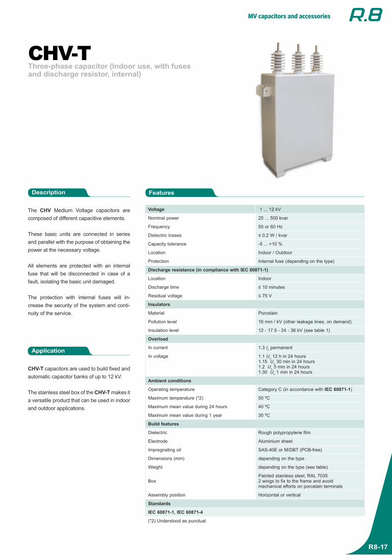
Three-phase capacitor (Indoor use, with fuses and discharge resistor, internal)
CHV-T
The CHV Medium Voltage capacitors are composed of different capacitive elements.
These basic units are connected in series and parallel with the purpose of obtaining the power at the necessary voltage.
All elements are protected with an internal fuse that will be disconnected in case of a fault, isolating the basic unit damaged.
The protection with internal fuses will in-crease the security of the system and conti-nuity of the service.
Application
CHV-T capacitors are used to build fixed and automatic capacitor banks of up to 12 kV.
The stainless steel box of the CHV-T makes it a versatile product that can be used in indoor and outdoor applications.
FeaturesDescription
Voltage 1 ... 12 kV
Nominal power 25 ... 500 kvar
Frequency 50 or 60 Hz
Dielectric losses ≤ 0.2 W / kvar
Capacity tolerance -5 ... +10 %
Location Indoor / Outdoor
Protection Internal fuse (depending on the type)
Discharge resistance (in compliance with IEC 60871-1)
Location Indoor
Discharge time ≤ 10 minutes
Residual voltage ≤ 75 V
Insulators
Material Porcelain
Pollution level 16 mm / kV (other leakage lines, on demand)
Insulation level 12 - 17.5 - 24 - 36 kV (see table 1)
Overload
In current 1.3 In permanent
In voltage 1.1 Un 12 h in 24 hours1.15 Un 30 min in 24 hours1.2 Un 5 min in 24 hours1.30 Un 1 min in 24 hours
Ambient conditions
Operating temperature Category C (in accordance with IEC 60871-1)
Maximum temperature (*2) 50 ºC
Maximum mean value during 24 hours 40 ºC
Maximum mean value during 1 year 30 ºC
Build features
Dielectric Rough polypropylene film
Electrode Aluminium sheet
Impregnating oil SAS-40E or M/DBT (PCB-free)
Dimensions (mm) depending on the type
Weight depending on the type (see table)
BoxPainted stainless steel, RAL 70352 wings to fix to the frame and avoid mechanical efforts on porcelain terminals
Assembly position Horizontal or vertical
Standards
IEC 60871-1, IEC 60871-4
(*2) Understood as punctual
MV capacitors and accessories
R8-18
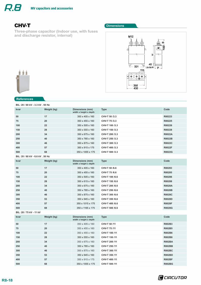
Three-phase capacitor (Indoor use, with fuses and discharge resistor, internal)
CHV-T
BIL: 20 / 60 kV - 3.3 kV . 50 Hz
kvar Weight (kg) Dimensions (mm)width x height x depth
Type Code
50 17 350 x 405 x 160 CHV-T 50 /3.3 R80223
75 20 350 x 455 x 160 CHV-T 75 /3.3 R80225
100 22 350 x 505 x 160 CHV-T 100 /3.3 R80226
150 28 350 x 555 x 160 CHV-T 150 /3.3 R80228
200 34 350 x 675 x 160 CHV-T 200 /3.3 R8022A
250 40 350 x 785 x 160 CHV-T 250 /3.3 R8022B
300 46 350 x 875 x 160 CHV-T 300 /3.3 R8022C
400 57 350 x 915 x 175 CHV-T 400 /3.3 R8022F
500 68 350 x 1055 x 175 CHV-T 500 /3.3 R8022G
BIL: 20 / 60 kV - 6.6 kV . 50 Hz
kvar Weight (kg) Dimensions (mm)width x height x depth
Type Code
50 17 350 x 405 x 160 CHV-T 50 /6.6 R80283
75 20 350 x 455 x 160 CHV-T 75 /6.6 R80285
100 22 350 x 505 x 160 CHV-T 100 /6.6 R80286
150 28 350 x 615 x 160 CHV-T 150 /6.6 R80288
200 34 350 x 675 x 160 CHV-T 200 /6.6 R8028A
250 40 350 x 785 x 160 CHV-T 250 /6.6 R8028B
300 46 350 x 875 x 160 CHV-T 300 /6.6 R8028C
350 53 350 x 945 x 160 CHV-T 350 /6.6 R8028D
400 57 350 x 1015 x 175 CHV-T 400 /6.6 R8028F
500 68 350 x 1165 x 175 CHV-T 500 /6.6 R8028G
BIL: 28 / 75 kV - 11 kV
kvar Weight (kg) Dimensions (mm)width x height x depth
Type Code
50 17 350 x 405 x 160 CHV-T 50 /11 R802B3
75 20 350 x 455 x 160 CHV-T 75 /11 R802B5
100 22 350 x 455 x 160 CHV-T 100 /11 R802B6
150 28 350 x 555 x 160 CHV-T 150 /11 R802B8
200 34 350 x 675 x 160 CHV-T 200 /11 R802BA
250 40 350 x 785 x 160 CHV-T 250 /11 R802BB
300 46 350 x 875 x 160 CHV-T 300 /11 R802BC
350 53 350 x 945 x 160 CHV-T 350 /11 R802BD
400 57 350 x 915 x 175 CHV-T 400 /11 R802BF
500 68 350 x 1055 x 175 CHV-T 500 /11 R802BG
Dimensions
References
350
430
M12
P
40
B
H
10
0
321 2x÷9x16
115
MV capacitors and accessories
R8-19
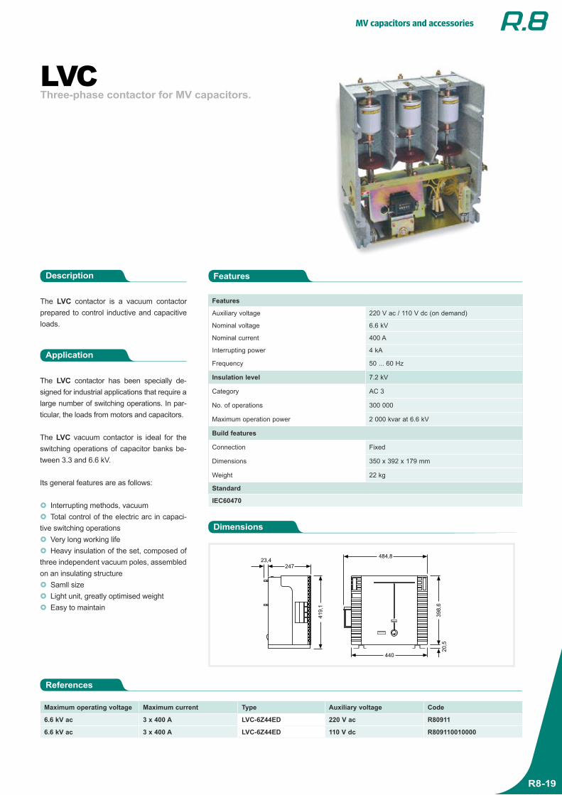
Three-phase contactor for MV capacitors. LVC
The LVC contactor is a vacuum contactor prepared to control inductive and capacitive loads.
Application
The LVC contactor has been specially de-signed for industrial applications that require a large number of switching operations. In par-ticular, the loads from motors and capacitors.
The LVC vacuum contactor is ideal for the switching operations of capacitor banks be-tween 3.3 and 6.6 kV.
Its general features are as follows:
Interrupting methods, vacuum Total control of the electric arc in capaci-
tive switching operations Very long working life Heavy insulation of the set, composed of
three independent vacuum poles, assembled on an insulating structure Samll size Light unit, greatly optimised weight Easy to maintain
FeaturesDescription
Features
Auxiliary voltage 220 V ac / 110 V dc (on demand)
Nominal voltage 6.6 kV
Nominal current 400 A
Interrupting power 4 kA
Frequency 50 ... 60 Hz
Insulation level 7.2 kV
Category AC 3
No. of operations 300 000
Maximum operation power 2 000 kvar at 6.6 kV
Build features
Connection Fixed
Dimensions 350 x 392 x 179 mm
Weight 22 kg
Standard
IEC60470
Dimensions
References
Maximum operating voltage Maximum current Type Auxiliary voltage Code
6.6 kV ac 3 x 400 A LVC-6Z44ED 220 V ac R80911
6.6 kV ac 3 x 400 A LVC-6Z44ED 110 V dc R809110010000
247
23,4
41
9,1
484,8
39
8,6
20
,5
440
MV capacitors and accessories
R8-20
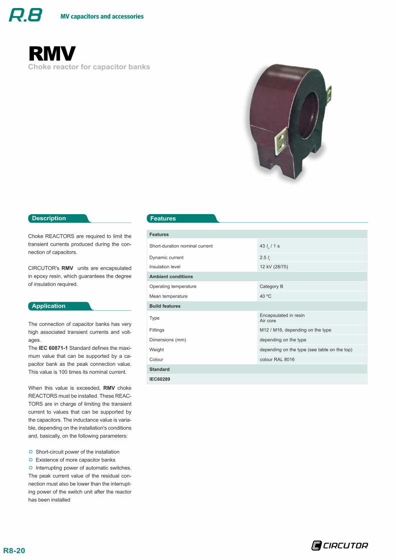
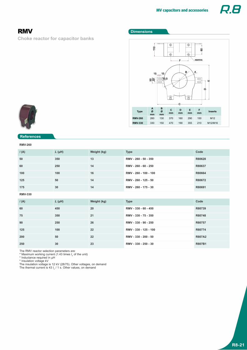
Choke reactor for capacitor banksRMV
Choke REACTORS are required to limit the transient currents produced during the con-nection of capacitors.
CIRCUTOR's RMV units are encapsulated in epoxy resin, which guarantees the degree of insulation required.
Application
The connection of capacitor banks has very high associated transient currents and volt-ages.The IEC 60871-1 Standard defines the maxi-mum value that can be supported by a ca-pacitor bank as the peak connection value. This value is 100 times its nominal current.
When this value is exceeded, RMV choke REACTORS must be installed. These REAC-TORS are in charge of limiting the transient current to values that can be supported by the capacitors. The inductance value is varia-ble, depending on the installation's conditions and, basically, on the following parameters:
Short-circuit power of the installation Existence of more capacitor banks Interrupting power of automatic switches.
The peak current value of the residual con-nection must also be lower than the interrupt-ing power of the switch unit after the reactor has been installed
FeaturesDescription
Features
Short-duration nominal current 43 In / 1 s
Dynamic current 2.5 It
Insulation level 12 kV (28/75)
Ambient conditions
Operating temperature Category B
Mean temperature 40 ºC
Build features
Type Encapsulated in resinAir core
Fittings M12 / M16, depending on the type
Dimensions (mm) depending on the type
Weight depending on the type (see table on the top)
Colour colour RAL 8016
Standard
IEC60289
MV capacitors and accessories
R8-21
Dimensions
References
Choke reactor for capacitor banksRMV
RMV-260
I (A) L (μH) Weight (kg) Type Code
50 350 13 RMV - 260 - 50 - 350 R80628
60 250 14 RMV - 260 - 60 - 250 R80637
100 100 16 RMV - 260 - 100 - 100 R80664
125 50 14 RMV - 260 - 125 - 50 R80672
175 30 14 RMV - 260 - 175 - 30 R80691
RMV-330
I (A) L (μH) Weight (kg) Type Code
60 450 20 RMV - 330 - 60 - 450 R80739
75 350 21 RMV - 330 - 75 - 350 R80748
90 250 26 RMV - 330 - 90 - 250 R80757
125 100 22 RMV - 330 - 125 - 100 R80774
200 50 22 RMV - 330 - 200 - 50 R807A2
250 30 23 RMV - 330 - 250 - 30 R807B1
The RMV reactor selection parameters are:* Maximum working current (1.43 times In of the unit)* Inductance required in μH* Insulation voltage kVThe insulation voltage is 12 kV (28/75). Other voltages, on demandThe thermal current is 43 In / 1 s. Other values, on demand
TypeAØ
mm
BØ
mm
Cmm
Dmm
Emm
Fmm Inserts
RMV-260 260 130 370 160 290 150 M12
RMV-330 330 150 470 190 355 210 M12/M16
MV Capacitor banks
R9-22
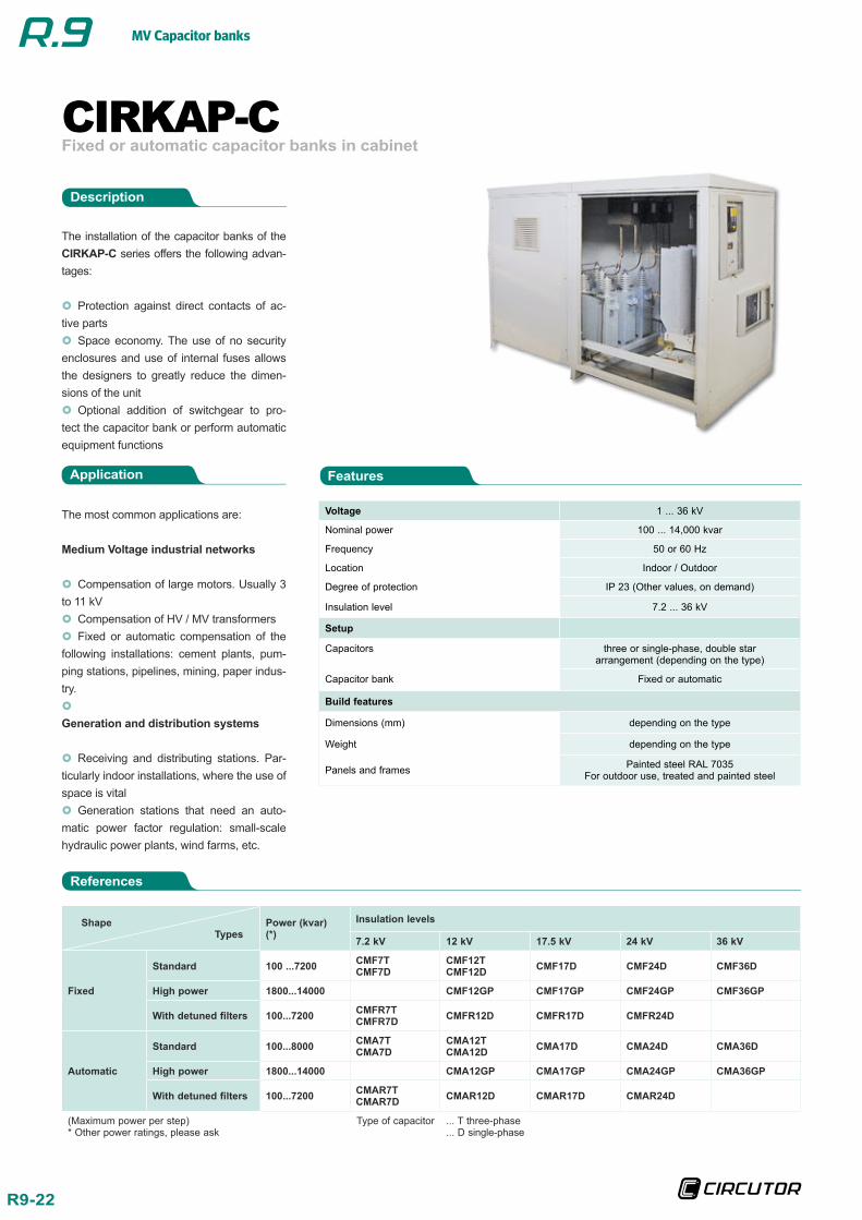
Fixed or automatic capacitor banks in cabinetCIRKAP-C
The most common applications are:
Medium Voltage industrial networks
Compensation of large motors. Usually 3 to 11 kV Compensation of HV / MV transformers Fixed or automatic compensation of the
following installations: cement plants, pum-ping stations, pipelines, mining, paper indus-try.
Generation and distribution systems
Receiving and distributing stations. Par-ticularly indoor installations, where the use of space is vital Generation stations that need an auto-
matic power factor regulation: small-scale hydraulic power plants, wind farms, etc.
Application
The installation of the capacitor banks of the CIRKAP-C series offers the following advan-tages:
Protection against direct contacts of ac-tive parts Space economy. The use of no security
enclosures and use of internal fuses allows the designers to greatly reduce the dimen-sions of the unit Optional addition of switchgear to pro-
tect the capacitor bank or perform automatic equipment functions
Features
Description
Voltage 1 ... 36 kV
Nominal power 100 ... 14,000 kvar
Frequency 50 or 60 Hz
Location Indoor / Outdoor
Degree of protection IP 23 (Other values, on demand)
Insulation level 7.2 ... 36 kV
Setup
Capacitors three or single-phase, double star arrangement (depending on the type)
Capacitor bank Fixed or automatic
Build features
Dimensions (mm) depending on the type
Weight depending on the type
Panels and frames Painted steel RAL 7035For outdoor use, treated and painted steel
References
Shape Types
Power (kvar)(*)
Insulation levels
7.2 kV 12 kV 17.5 kV 24 kV 36 kV
Fixed
Standard 100 ...7200 CMF7TCMF7D
CMF12TCMF12D CMF17D CMF24D CMF36D
High power 1800...14000 CMF12GP CMF17GP CMF24GP CMF36GP
With detuned filters 100...7200 CMFR7TCMFR7D CMFR12D CMFR17D CMFR24D
Automatic
Standard 100...8000 CMA7TCMA7D
CMA12TCMA12D CMA17D CMA24D CMA36D
High power 1800...14000 CMA12GP CMA17GP CMA24GP CMA36GP
With detuned filters 100...7200 CMAR7TCMAR7D CMAR12D CMAR17D CMAR24D
(Maximum power per step)* Other power ratings, please ask
Type of capacitor ... T three-phase... D single-phase
MV Capacitor banks
R9-23
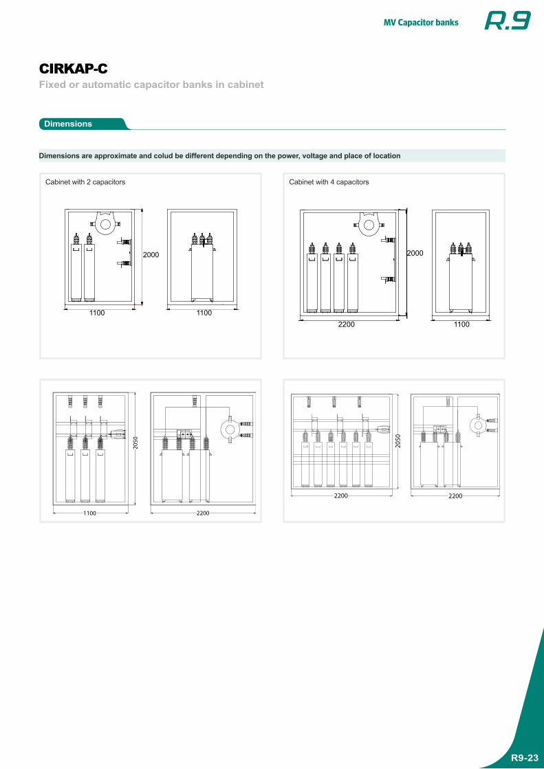
Dimensions
Fixed or automatic capacitor banks in cabinetCIRKAP-C
1100 1100
2000
2200
2000
1100
1100 2200
2050
2200 2200
2050
Dimensions are approximate and colud be different depending on the power, voltage and place of location
Cabinet with 2 capacitors Cabinet with 4 capacitors
MV Capacitor banks
R9-24
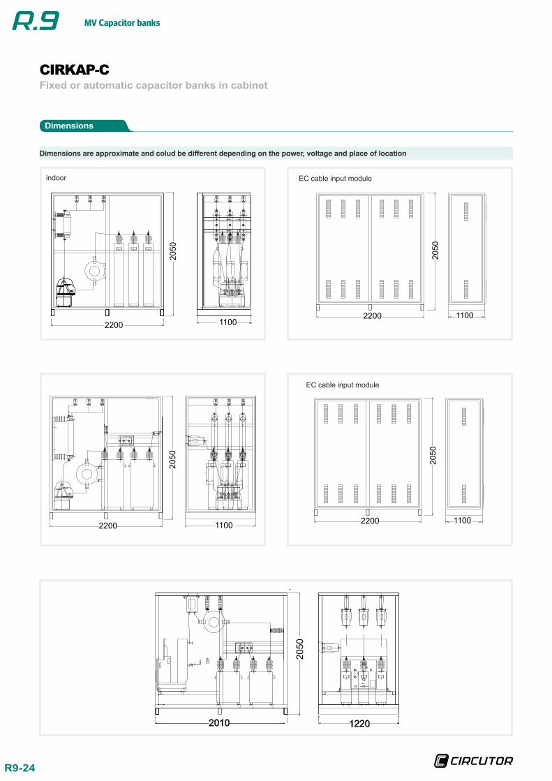
Dimensions
Fixed or automatic capacitor banks in cabinetCIRKAP-C
EC cable input module
11002200
2050
2200 1100
2050
2200 1100
2050
2050
11002200
2010
2050
1220
Dimensions are approximate and colud be different depending on the power, voltage and place of location
indoor
EC cable input module
MV Capacitor banks
R9-25
High-powered capacitor banks in cabinetCIRKAP-GP
CIRKAP-CMFR / CMAR
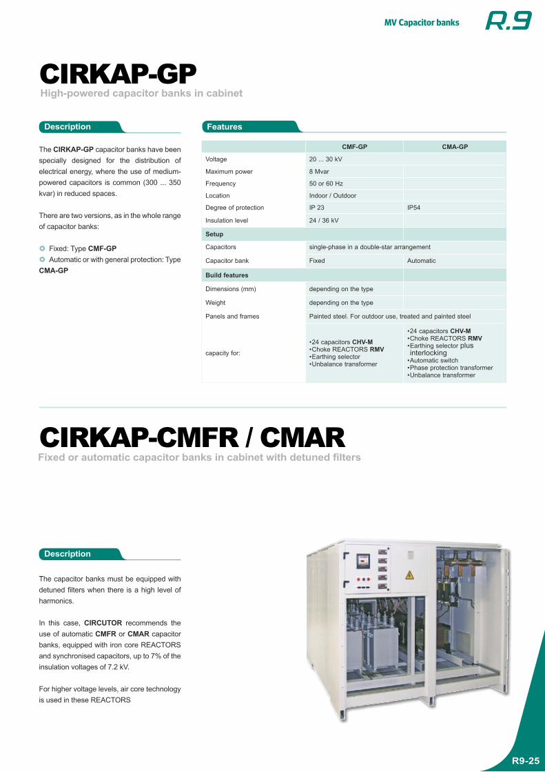
The CIRKAP-GP capacitor banks have been specially designed for the distribution of electrical energy, where the use of medium-powered capacitors is common (300 ... 350 kvar) in reduced spaces.
There are two versions, as in the whole range of capacitor banks:
Fixed: Type CMF-GP Automatic or with general protection: Type
CMA-GP
The capacitor banks must be equipped with detuned filters when there is a high level of harmonics.
In this case, CIRCUTOR recommends the use of automatic CMFR or CMAR capacitor banks, equipped with iron core REACTORS and synchronised capacitors, up to 7% of the insulation voltages of 7.2 kV.
For higher voltage levels, air core technology is used in these REACTORS
Fixed or automatic capacitor banks in cabinet with detuned filters
CMF-GP CMA-GP
Voltage 20 ... 30 kV
Maximum power 8 Mvar
Frequency 50 or 60 Hz
Location Indoor / Outdoor
Degree of protection IP 23 IP54
Insulation level 24 / 36 kV
Setup
Capacitors single-phase in a double-star arrangement
Capacitor bank Fixed Automatic
Build features
Dimensions (mm) depending on the type
Weight depending on the type
Panels and frames Painted steel. For outdoor use, treated and painted steel
capacity for:
• 24 capacitors CHV-M• Choke REACTORS RMV• Earthing selector• Unbalance transformer
• 24 capacitors CHV-M• Choke REACTORS RMV• Earthing selector plus interlocking
• Automatic switch• Phase protection transformer• Unbalance transformer
Description
Description
Features
MV Capacitor banks
R9-26
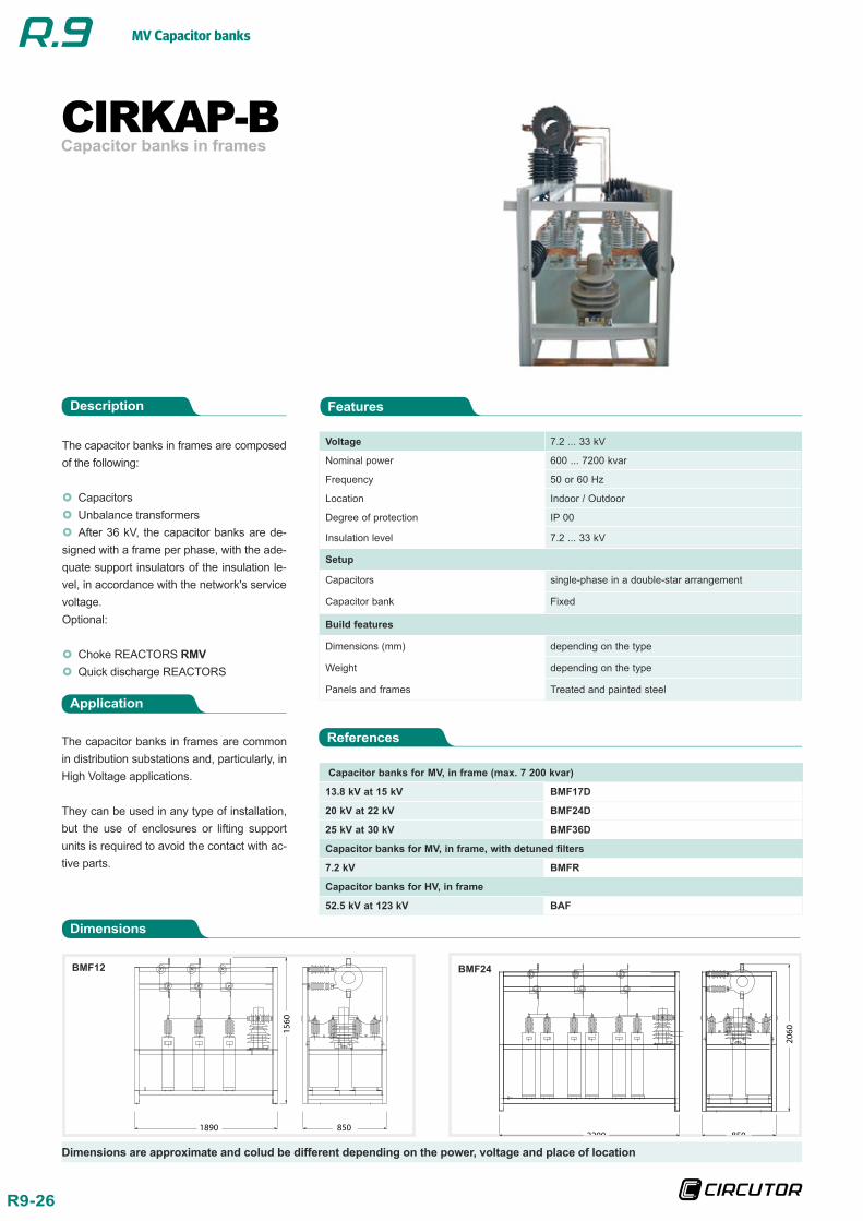
Capacitor banks in framesCIRKAP-B
The capacitor banks in frames are composed of the following:
Capacitors Unbalance transformers After 36 kV, the capacitor banks are de-
signed with a frame per phase, with the ade-quate support insulators of the insulation le-vel, in accordance with the network's service voltage.Optional:
Choke REACTORS RMV Quick discharge REACTORS
Application
The capacitor banks in frames are common in distribution substations and, particularly, in High Voltage applications.
They can be used in any type of installation, but the use of enclosures or lifting support units is required to avoid the contact with ac-tive parts.
FeaturesDescription
Voltage 7.2 ... 33 kV
Nominal power 600 ... 7200 kvar
Frequency 50 or 60 Hz
Location Indoor / Outdoor
Degree of protection IP 00
Insulation level 7.2 ... 33 kV
Setup
Capacitors single-phase in a double-star arrangement
Capacitor bank Fixed
Build features
Dimensions (mm) depending on the type
Weight depending on the type
Panels and frames Treated and painted steel
Dimensions
References
Capacitor banks for MV, in frame (max. 7 200 kvar)
13.8 kV at 15 kV BMF17D
20 kV at 22 kV BMF24D
25 kV at 30 kV BMF36D
Capacitor banks for MV, in frame, with detuned filters
7.2 kV BMFR
Capacitor banks for HV, in frame
52.5 kV at 123 kV BAF
BMF12 BMF24
1890
1560
8502200 850
2060
Dimensions are approximate and colud be different depending on the power, voltage and place of location

MV Capacitor banks
R9-27
Electro Hamand
No. 44/ Shahid Torabi Goudarzi Str./ South Lalehzar Ave./ Tehran-Iran Tel: (+98-21) -33974808, 33974809, 33936263,33925714, 33970485, 33970486, 33113073, 33973953 Fax : (+98-21)- 33117956
www.electrohamand.com