Embed Size (px)
Citation preview

The contents of this literature are as of Mar. 2010This catalog is printed with soy ink.MGS-LS-1004-EN-C
http: //www.mgscale.com
Magnescale Co., Ltd.
Industriestaße 24 77815 BühlTel. 07223/91249-30 Fax. 07223/91249-59www.gebotech.de info(at)gebotech.de
Ihr Fachhandelspartner:
echTGeBo GmbH
Laserscale® General Catalog
Shinagawa Intercity Tower A-18F, 2-15-1, Konan, Minato-ku, Tokyo 108-6018, JAPAN
Magnescale Co., Ltd.
HeadquatersTokyo OfficeNagoya OfficeOsaka OfficeInternational Sales DepartmentMagnescale Americas Inc. Magnescale Europe GmbH
45 Suzukawa, Isehara-shi, Kanagawa 259-1146, Japan45 Suzukawa, Isehara-shi, Kanagawa 259-1146, Japan2-35-16, Meieki, Nakamura-ku, Nagoya Aichi, 450-0002, JAPAN2-14-6, Nishi-Nakajima, Yodogawa-ku, Osaka 532-0011, JAPAN45 Suzukawa, Isehara-shi, Kanagawa 259-1146, Japan5740 Warland Drive, Cypress, CA 90630, USAAntoniusstrasse 14, 73249 Wernau, Germany
TEL.+81(0)463-92-1011TEL.+81(0)463-92-7972TEL.+81(0)52-587-1823TEL.+81(0)6-6305-3101TEL.+81(0)463-92-7971TEL.+1(949)770-8400 TEL.+49(0) 7153 934 291
FAX.+81(0)463-92-1012FAX.+81(0)463-92-7978FAX.+81(0)52-587-1848FAX.+81(0)6-6304-6586FAX.+81(0)463-92-7978FAX.+1(949)770-8408 FAX.+49(0)7153 934 240
:::::::
Magnescale Co., Ltd.
PD LD
Laserscale®
Magnescale Corporation
ContentsSafety
Traceability
Contents
Introduction
Principle
Application
Lineup
BS78
BS65-R
BH25-RE /BH25-NE
BH20-RE /BH20-NE
BH200-RE /BH200-NE
BL57-RE /BL57-NE
BL55-RU
BD96
BD95
Connection Cable
Technology
2
2
3
4
6
7
8
10
14
16
18
20
22
28
30
32
34
35
2 3
* The product name "Laserscale" is trademark of Magnescale Corporation.
Safety
We have met:
Our products comply with CE Marking requirements, have acquired UL certifications and meet other regulations, ensuring safe use the world over.
* When using our devices with machines to which the European Machinery Drirective applies, please make sure that the devices when installed on the machines fulfil the applicable requirements of the Directive.
* Standards or regulations to be complied with may vary by product.
•EMC Directives(CE)
EMI: EN 55011 Group 1 Class A / 91
EMS: EN 61000-6-2
•FCC regulation
FCC Part 15 Subpart B Class A
for Products with built-in AC power supply:
•UL 61010-1
for Products with Laser:
•DHHS Class 1 (21CFR1040.10)
The total quality control system that operates throughout the entire design and production process ensures products with enhanced safety, high quality, and high reliability that match our customers’ requirements. The company is certified for length calibration in compliance with the traceability system required by the “Weights and Measures Act,” and has been granted ISO 9001 certification, which is the international standard for quality assurance.
No compromise for high-accuracy products
TraceabilityTraceability Flow Chart (Length)
National Primary Standards
National Institute of Advanced Industrial Science and Technology (AIST)Iodine saturation absorption stabilized He-Ne laser at 633nmSpeed of light (laser) C=299792458m/s
Nationalstandards
International Committee for Weightsand Measures (CIPM)
International Bureau of Weights and Measures (BIPM)
NationalSecondaryStandards
PracticalStandards
Iodine saturation absorption stabilized He-Ne laser at 633nm
Magnescale Corporation
Calibration product (Customer,s equipment)
Stabilized He-Ne Laser (633nm)
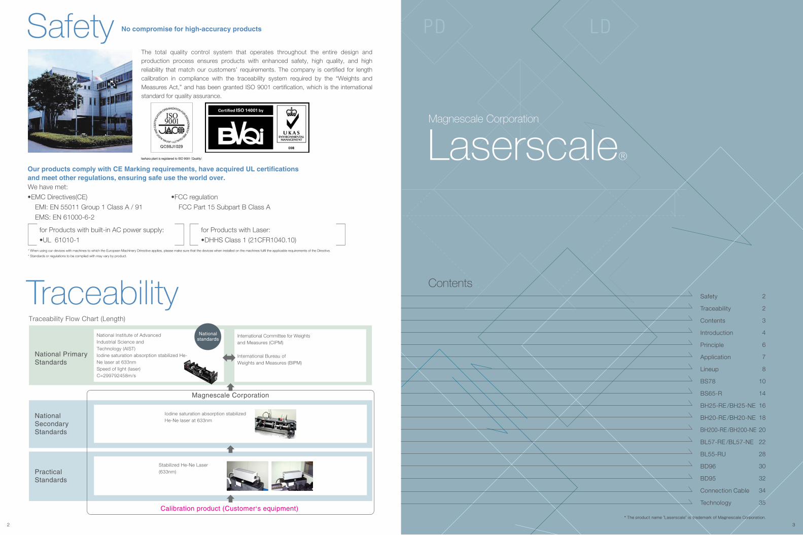
High-resolution scale with signal wavelength of approx. 138nm outperforms light wave interferometer systems High stability : Free from humidity, air pressure, or air disturbances Easy installation & maintenance
What's Lasers cale?The world of super-resolution is going further than 1nm
High stability against external disturbances (air pressure disturbances/fluctuations)
BS seriesSignal wavelength:
138nm
Model Output
Binary
Number of divisions
8000
Resolutions
17 pm
Maximum response speed
400mm/s
Unaffected by the change of clearance between head & scaleEasy installation
Clearance change
Track direction
Clearance direction
138nm
Air pressure effect
Pos
ition
(40n
m/d
iv)
Laserinterferometer
LASERSCALE
Time(min)0 800
Lissajous figure
4 5
Laserscale easily achieves measurement and control by ultra high resolution less than 1nm.
Sinusoidal wave of approx. 138nm signal period is generated by a hologram scale with high diffraction efficiency and
a high resolution detecting head based on grating interference method,strong against disturbance
by air pressure or current, plus easy to install (BS series). Signal distortion in principle remains minimal
at high S/N ratio. The highest resolution reaches 17pm in combination with a
interpolator featuring automatic compensation.
Optical axis shiftby change of Clearance
[Easy to handle]Large tolerance for installationEasy installation, remarkable for ultra-high resolution, accuracy and non-contact detection
No electric adjustment after installationEven with high tolerance for installation, no electric adjustmentrequired after installation.
Protected holographic gratingHolographic grating is protected with cover glasses, which guards the grating against external pressure. The glass can be wiped out to clean dust and dirt.
Ultra-high resolutionVolume holography technology of Laserscale®
achieves high diffraction efficiency to
generate high S/N signal and big output signal.
Highest resolution 17pmOne count movement by holographic grating
of 550nm wave length diffracts interfering signal
to 4 periods, resulting 1/4 of original signal (approx. 0.14μm). And signals go
through electrical Interpolator, it will be maxmum 17pm resolution.
Ultra-high resolution and high speed responseGrating interference principle linear encoder generates signal of approx.
0.14μm period, that is 1/140 of conventional linear encoder with 20μm signal period.
Also using our interpolator, 17pm resolution and high response as max.
response speed 400mm/s are available.
AB quadrature 32 60mm/s4.31 nm
Holographic grating
Holographic scale
Cover glass
PD LDPD LD
Yoing direction:±6min
Pitching direction:±6min
Rolling direction:±10min
Track direction:±0.2mm
BL Series
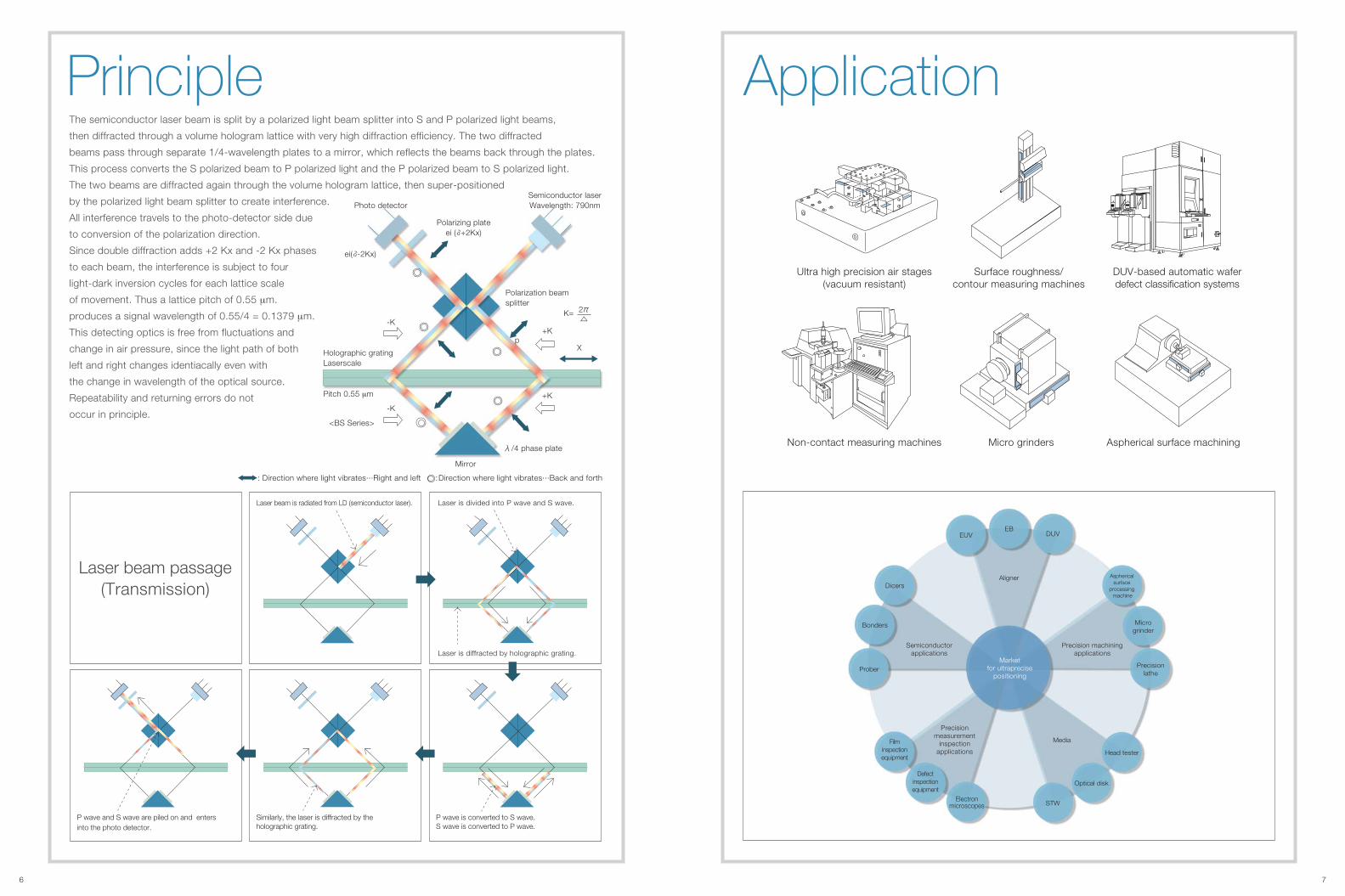
Aligner
EUVEB
DUV
Aspherical surface
processing machine
Microgrinder
Precisionlathe
Semiconductorapplications
Dicers
Bonders
Prober
Precisionmeasurement
inspectionapplications
Filminspectionequipment
Defectinspectionequipment
Electronmicroscopes
Media
Head tester
Optical disk
STW
Ultra high precision air stages(vacuum resistant)
Surface roughness/contour measuring machines
DUV-based automatic waferdefect classification systems
Non-contact measuring machines Micro grinders Aspherical surface machining
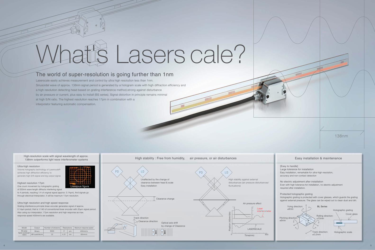
Laser beam is radiated from LD (semiconductor laser). Laser is divided into P wave and S wave.
Laser beam passage(Transmission)
Principle
Laser is diffracted by holographic grating.
6 7
ApplicationThe semiconductor laser beam is split by a polarized light beam splitter into S and P polarized light beams,
then diffracted through a volume hologram lattice with very high diffraction efficiency. The two diffracted
beams pass through separate 1/4-wavelength plates to a mirror, which reflects the beams back through the plates.
This process converts the S polarized beam to P polarized light and the P polarized beam to S polarized light.
The two beams are diffracted again through the volume hologram lattice, then super-positioned
by the polarized light beam splitter to create interference.
All interference travels to the photo-detector side due
to conversion of the polarization direction.
Since double diffraction adds +2 Kx and -2 Kx phases
to each beam, the interference is subject to four
light-dark inversion cycles for each lattice scale
of movement. Thus a lattice pitch of 0.55 μm.
produces a signal wavelength of 0.55/4 = 0.1379 μm.
This detecting optics is free from fluctuations and
change in air pressure, since the light path of both
left and right changes identiacally even with
the change in wavelength of the optical source.
Repeatability and returning errors do not
occur in principle.
Precision machiningapplications
P wave and S wave are piled on and enters into the photo detector.
Similarly, the laser is diffracted by the holographic grating.
P wave is converted to S wave.S wave is converted to P wave.
Marketfor ultraprecise
positioning
<BS Series>
: Direction where light vibrates···Right and left : Direction where light vibrates···Back and forth
Photo detectorSemiconductor laserWavelength: 790nm
ei( -2Kx)
Polarization beamsplitter
Holographic gratingLaserscale
Pitch 0.55 μm
-K
-K
+K
+Kp
Mirror
K=
X
Polarizing plateei ( +2Kx)
/4 phase plate
8 9
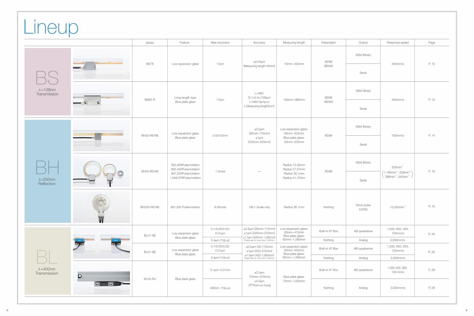
Series Feature Response speed Page
LineupMax.resolution Measuring length
0.4μm (1Vp-p) 3,000mm/s
Interpolator
Nothing
Output
40bit Binary
Analog
Accuracy
40bit Binary
Serial
BS78 Low expansion glass 400mm/s P. 1017pm 10mm~420mmBD96(BD95)
±0.04μm(Measuring length 40mm)
Serial
BS65-RLong-length typeBlue plate glass
400mm/s P. 1217pm 160mm~960mmBD96(BD95)
40bit Binary
Serial
BH25-RE/NELow expansion glass
Blue plate glass700mm/s P, 140.03125nm
Low expansion glass:30mm~420mmBlue plate glass:30mm~420mm
BD96
±0.5μm(30mm-170mm)
±1μm(220mm-420mm)
BL55-RU Blue plate glass
P, 28
P, 28
1,500, 650, 300, 120 mm/s
3,000mm/s
0.1μm~0.01nm
400nm (1Vp-p)
Blue plate glass:70mm~1,020mm
Built-in I/F Box
Nothing
AB quadrature
Analog
±2.5μm (70mm-370mm)
±4.5μm (370mm or more)
BH200-RE/NE 907,200 Pulse/rotation P, 1813,000min-16.93nrad Radius 36.1mm NothingClock pulse
(LVDS)r36.1 Scale only
BL57-RE
BL57-NE
Low expansion glassBlue plate glass
P, 20
P, 20
0.1/0.05/0.02/0.01μm
Low expansion glass:30mm~410mmBlue plate glass:60mm~1,060mm
Low expansion glass:30mm~420mmBlue plate glass:60mm~1,060mm
0.4μm (1Vp-p)
Low expansion glassBlue plate glass
0.1/0.05/0.02/0.01μm
1,500, 650, 300,120mm/s
3,000mm/s
1,500, 650, 300,120mm/s
Built-in I/F Box
Nothing
Built-in I/F Box
AB quadrature
Analog
AB quadrature
±0.5μm (30mm-170mm)
±1μm (220mm-370mm)
±1.5μm (420mm-1,060mm)Please ask for more than 1,060mm
±0.5μm (30-170mm)
±1μm (220-370mm)
±1.5μm (420-1,060mm)Please ask for more than 1,060mm
BS =138nm
Transmission
BH =250nmReflection
BL =400nm
Transmission
40bit Binary
Serial
BH20-RE/NE
302,400Pulse/rotation680,400Pulse/rotation907,200Pulse/rotation
1,048,576Pulse/rotation
P, 161.5nrad
Radius 12.03mmRadius 27.07mmRadius 36.1mm
Radius 41.72mm
BD96-555min-1
( )1,190min-1, 529min-1
396min-1, 343min-1
L<460:(0.1+0.4L/100)μmL>460:3μmp-p
L:Measuring length(mm)=

BS BS78(with/without origin)
10 11
Actual size
• High-resolution scale with signal wavelength of approx. 138nm,
outperforming light wave interferometer systems
• High stability, unaffected by humidity, air pressure and air disturbances
• Reference point accuracy : ±0.1μm
• Scale accuracy : ±0.04μm or better (measuring length : 40 mm)
• Completely non-contact design Return error is virtually eliminated.
• Special non-magnetic and vacuum-compatible models available
• Using low expansion glass : -0.7 x 10⁻⁶/ ˚C
(measuring length : 10 to 420 mm)
High-speed and high-resolution, while maintaining stable, ultraprecision measuring.
Ideal for precision stages, semiconductor inspection/manufacturing systems,
and ultraprecision processing machines.
Type example : BS78-220R
R: with reference point; RS: high accuracy with reference point N: without reference point; NS: high accuracy without reference point
Effective length
External Dimensions
L1 1
50 3*
60
L3 1 L3 1L2 1 L2 1
2538
Spacer t=2
10
25±0.2* 25±0.2* 25±0.2* 25±0.2* 25±0.2*
2-M4 reference plate mounting screw
N-M4 scale clamp mounting screw
Scale movementReference pointdetection direction
38 0.2*46 0.33
29.5
43.5
32.7
0.3
Detector head mounting screw2-M3x30
45.9 15
40.5
ø7Cable length3000
Reference signal detection position
Scale signal detection position
M0.010.01
*A
4.6
6
13.19.8 0.2*
0.03 A*
30.5
145
13.3 6.8
Reference plate t=2
Referencehole
2550
42
60
9 14
3-ø5ø4+0.05 0
2-ø5
Scale clamp
255
12
38
ø4+0.05 0
4+
0.05
0
Unit: mm
ModelBS78-40R (RS)BS78-120R (RS)BS78-170R (RS)BS78-220R (RS)BS78-370R (RS)BS78-420R (RS)
L166
146196246396446
L2—5075
10075
100
L3————75
100
N2666
1010
Unit: mm
ModelBS78-70R (RS)BS78-270R (RS)BS78-320R (RS)
L196
296346
L2—
120120
N488
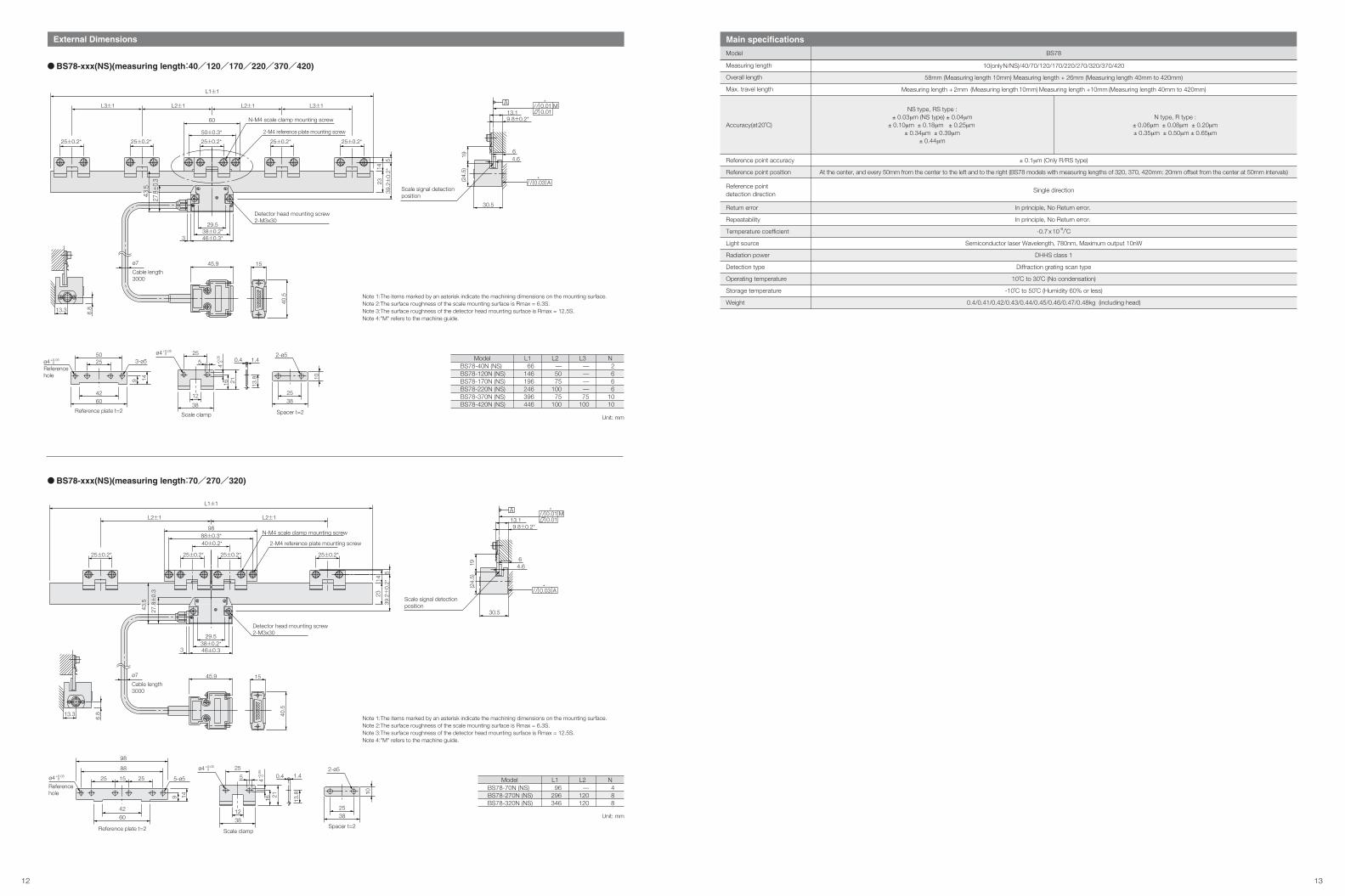
Note 1:The items marked by an asterisk indicate the machining dimensions on the mounting surface.Note 2:The surface roughness of the scale mounting surface is Rmax = 6.3S.Note 3:The surface roughness of the detector head mounting surface is Rmax = 12.5S.Note 4:"M" refers to the machine guide.Note 5:Reference point detection direction : Standard (Scale movement direction with the head stationary)
Note 1:The items marked by an asterisk indicate the machining dimensions on the mounting surface.Note 2:The surface roughness of the scale mounting surface is Rmax = 6.3S.Note 3:The surface roughness of the detector head mounting surface is Rmax = 12.5S.Note 4:"M" refers to the machine guide.Note 5:Reference point detection direction : Standard (Scale movement direction with the head stationary)
L1 1
Spacer t=2
10
2538
Detector head mounting screw2-M3x30
L2 1 L2 1
Scale movementReference pointdetection direction
40 0.2*88 0.3*
25 0.2* 25 0.2* 25 0.2* 25 0.2*
98N-M4 scale clamp mounting screw
2-M4 reference plate mounting screw
39.2
0.2*
14
523
38 0.2*46 0.3
43.5
29.5
3
32.7
0.3
1545.9
40.5
ø7Cable length3000
6.813.3
Reference signal detection position
Scale signal detection position
M0.010.01
*A
0.03 A*
9.8 0.2*13.1
30.5
6
4.6
Scale clamp
38
25
5
12
1.4
16 21
0.4
13.8
ø4+0.05 0
4+0.
05 0
Referencehole
9 14
4260
25 15 25
88
98
5-ø52-ø5
ø4+0.05 0
Reference plate t=2
BS78-xxxN(NS)(measuring length:40/120/170/220/370/420)
BS78-xxxN(NS)(measuring length:70/270/320)
1.40.4
N type, R type :± 0.06μm ± 0.08μm ± 0.20μm± 0.35μm ± 0.50μm ± 0.65μm
NS type, RS type :± 0.03μm (NS type) ± 0.04μm
± 0.10μm ± 0.18μm ± 0.25μm ± 0.34μm ± 0.39μm
± 0.44μm
Single direction
Measuring length
Overall length
Max. travel length
Reference point accuracy
Reference point position
Return error
Repeatability
Temperature coefficient
Light source
Radiation power
Detection type
Operating temperature
Storage temperature
Weight
± 0.1μm (Only R/RS type)
At the center, and every 50mm from the center to the left and to the right (BS78 models with measuring lengths of 320, 370, 420mm: 20mm offset from the center at 50mm intervals)
In principle, No Return error.
In principle, No Return error.
-0.7 x 10⁻⁶/˚C
Semiconductor laser Wavelength, 780nm, Maximum output 10nW
DHHS class 1
Diffraction grating scan type
10˚C to 30˚C (No condensation)
-10˚C to 50˚C (Humidity 60% or less)
0.4/0.41/0.42/0.43/0.44/0.45/0.46/0.47/0.48kg (including head)
Main specifications
Model BS78
Accuracy(at20˚C)
Reference point detection direction
10(onlyN/NS)/40/70/120/170/220/270/320/370/420
58mm (Measuring length 10mm) Measuring length + 26mm (Measuring length 40mm to 420mm)
Measuring length + 2mm (Measuring length 10mm) Measuring length +10mm (Measuring length 40mm to 420mm)
12 13
External Dimensions
L1 1
Spacer t=2
2538
10
Unit: mm
ModelBS78-40N (NS)BS78-120N (NS)BS78-170N (NS)BS78-220N (NS)BS78-370N (NS)BS78-420N (NS)
L166
146196246396446
L2—5075
10075
100
L3————75
100
N2666
1010
BS78-xxx(NS)(measuring length:40/120/170/220/370/420)
BS78-xxx(NS)(measuring length:70/270/320)
Unit: mm
ModelBS78-70N (NS)BS78-270N (NS)BS78-320N (NS)
L196
296346
L2—
120120
N488
L1 1
L3 1 L3 1L2 1 L2 1
2-M4 reference plate mounting screw
N-M4 scale clamp mounting screw
50 0.3*
25 0.2* 25 0.2* 25 0.2* 25 0.2* 25 0.2*
60
39.2
0.2*
5
1423
3
29.538 0.2*46 0.3*
Detector head mounting screw2-M3x30
ø7
Cable length3000
45.9 15
40.5
13.3 6.8
Reference plate t=2
Referencehole
5025
4260
9 14
3-ø5ø4+0.05 0
ø4+0.05 0
4+0.
05 0
Scale clamp
25
5
12
38
16 21
0.4 1.4
13.8
2-ø5
9.8 0.2*
30.5
13.1
64.619
(24.
5)
Scale signal detectionposition
M0.010.01
*
A0.03*
L2 1 L2 1
2-M4 reference plate mounting screw
N-M4 scale clamp mounting screw
40 0.2*88 0.3*
98
25 0.2* 25 0.2* 25 0.2* 25 0.2*
14
539
.20.
2*
23
43.5
3
Detector head mounting screw2-M3x30
29.538 0.2*46 0.3
27.8
0.3
ø7
Cable length3000
1545.9
40.5
13.3
6.8
Referencehole
Reference plate t=2
9 14
42
60
25 15 25
98
88
5-ø5ø4+0.05 0
ø4+0.05 0
4+
0.05
0
Scale clamp
38
25
5
12
1.4
1621
0.4
13.8
Spacer t=2
10
2538
2-ø5
9.8 0.2*
30.5
13.1
4.66
19(2
4.5)
M0.010.01
*
A0.03*
Scale signal detection position
Note 1:The items marked by an asterisk indicate the machining dimensions on the mounting surface.Note 2:The surface roughness of the scale mounting surface is Rmax = 6.3S.Note 3:The surface roughness of the detector head mounting surface is Rmax = 12.5S.Note 4:"M" refers to the machine guide.
Note 1:The items marked by an asterisk indicate the machining dimensions on the mounting surface.Note 2:The surface roughness of the scale mounting surface is Rmax = 6.3S.Note 3:The surface roughness of the detector head mounting surface is Rmax = 12.5S.Note 4:"M" refers to the machine guide.
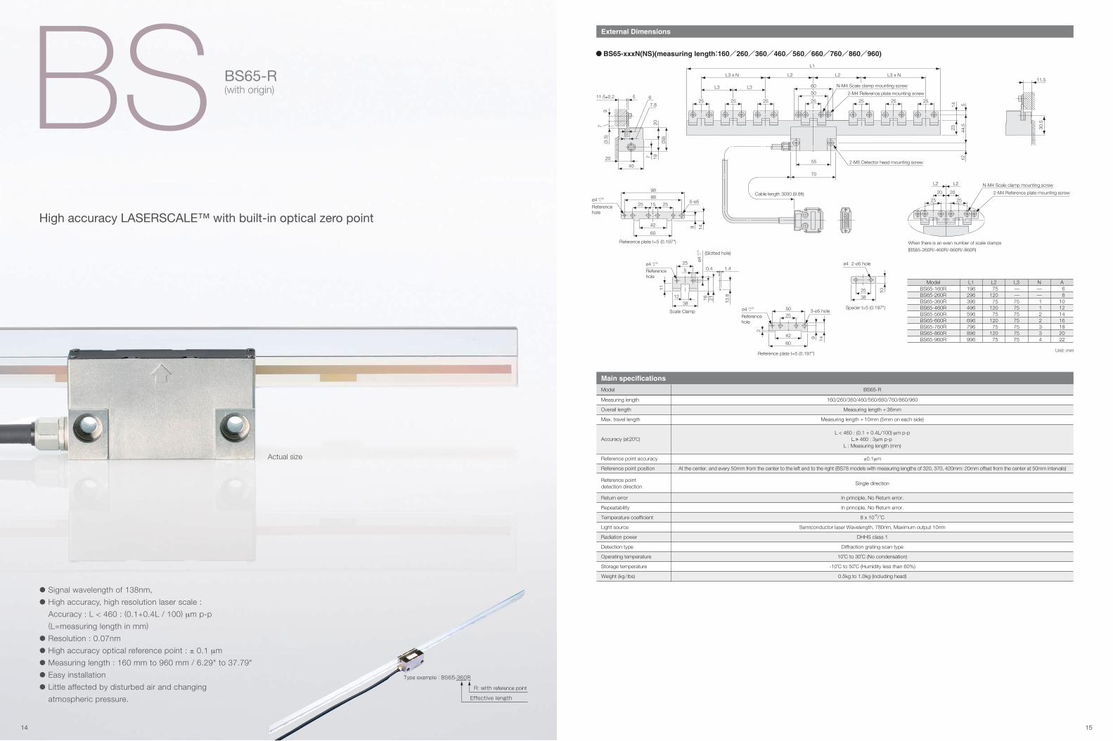
BS BS65-R(with origin)
External Dimensions
Actual size
• Signal wavelength of 138nm,
• High accuracy, high resolution laser scale :
Accuracy : L < 460 : (0.1+0.4L / 100) μm p-p
(L=measuring length in mm)
• Resolution : 0.07nm
• High accuracy optical reference point : ± 0.1 μm
• Measuring length : 160 mm to 960 mm / 6.29" to 37.79"
• Easy installation
• Little affected by disturbed air and changing
atmospheric pressure.
Unit: mm
ModelBS65-160RBS65-260RBS65-360RBS65-460RBS65-560RBS65-660RBS65-760RBS65-860RBS65-960R
L1196296396496596696796896996
L275
12075
12075
12075
12075
L3——75757575757575
N A——1122334
68
10121416182022
High accuracy LASERSCALE™ with built-in optical zero point
11.5
30.5
11.5±0.2 6
7.8
5
20
40
(39)
20197
79
(3.5
)
70
L1
L3 x N L3 x N
L3 L3
L2L2
55
N-M4 Scale clamp mounting screw
2-M4 Reference plate mounting screw
2-M5 Detector head mounting screw
44.5
512
2314
Cable length 3000 (9.8ft)
25 25 25 25 25 2525
50
60
20 20
L2 L2 N-M4 Scale clamp mounting screw
2-M4 Reference plate mounting screw
25 25
When there is an even number of scale clamps
(BS65-260R/-460R/-660R/-860R)
9888
1525 25
60
14942
5-ø5Referencehole
Reference plate t=5 (0.197")
ø4 +0.05 0
2538
10
2-ø5 holeø4
Spacer t=5 (0.197")
9 14
5025
42
60
3-ø5 holeReferencehole
Reference plate t=5 (0.197")
2
ø4 +0.05 0
13.816 21
25
5
3812
0.4 1.4
11
Scale Clamp
(Slotted hole)
ø4 +0.05 0
ø4+
0.05
0
Referencehole
Measuring length
Overall length
Max. travel length
Reference point accuracy
Reference point position
Return error
Repeatability
Temperature coefficient
Light source
Radiation power
Detection type
Operating temperature
Storage temperature
Weight (kg/ lbs)
160/260/360/460/560/660/760/860/960
Measuring length + 36mm
Measuring length + 10mm (5mm on each side)
±0.1μm
At the center, and every 50mm from the center to the left and to the right (BS78 models with measuring lengths of 320, 370, 420mm: 20mm offset from the center at 50mm intervals)
In principle, No Return error.
In principle, No Return error.
8 x 10⁻⁶/ ˚C
Semiconductor laser Wavelength, 780nm, Maximum output 10nm
DHHS class 1
Diffraction grating scan type
10˚C to 30˚C (No condensation)
-10˚C to 50˚C (Humidity less than 60%)
0.5kg to 1.0kg (including head)
Main specifications
Model BS65-R
L < 460 : (0.1 + 0.4L/100) μm p-pL ≥ 460 : 3μm p-p
L : Measuring length (mm)
Single direction
Accuracy (at20˚C)
Reference point detection direction
Type example : BS65-360R
R: with reference point
Effective length
BS65-xxxN(NS)(measuring length:160/260/360/460/560/660/760/860/960)
14 15
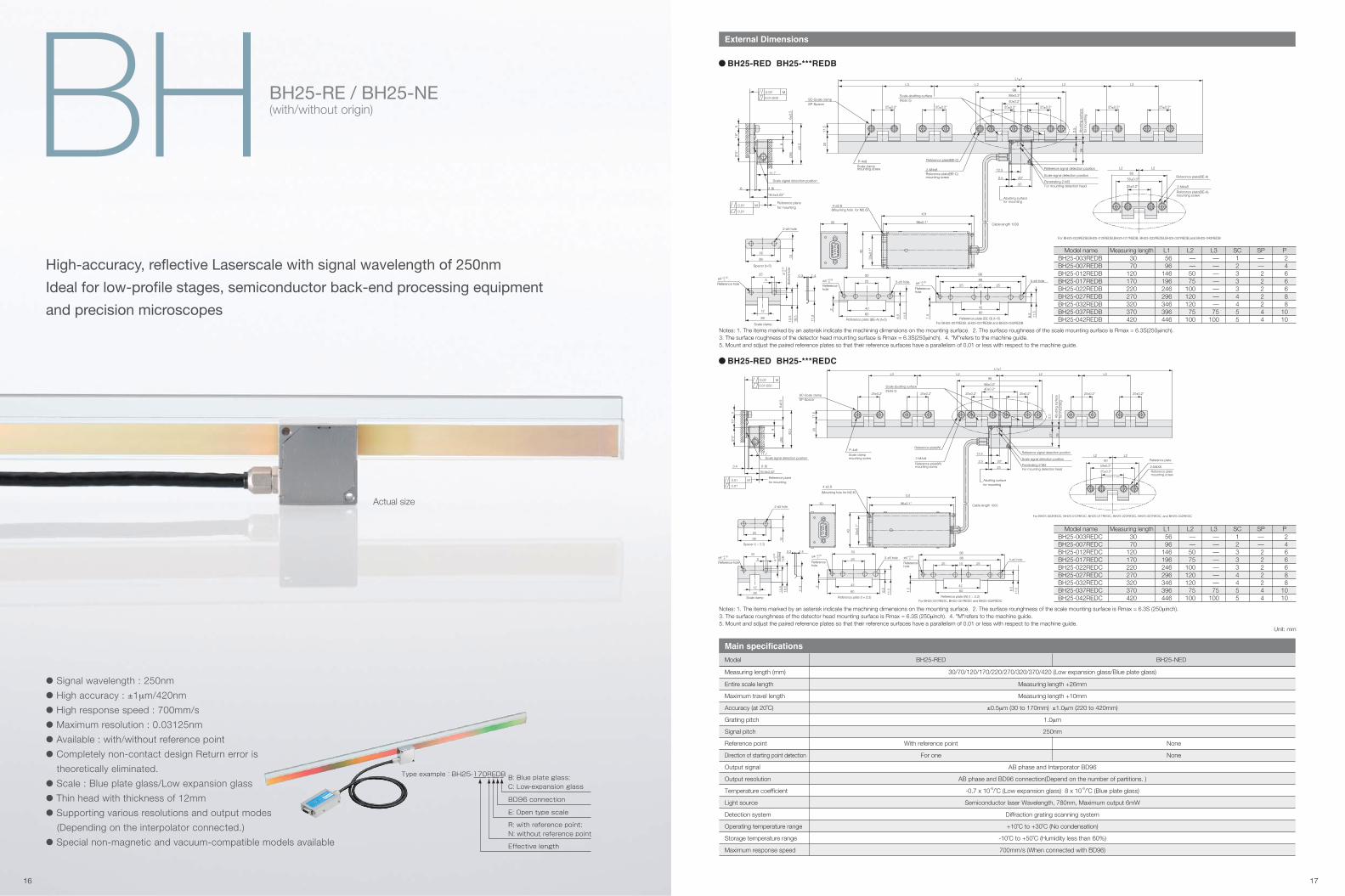
BH BH25-RE / BH25-NE(with/without origin)
Actual size
• Signal wavelength : 250nm
• High accuracy : ±1μm/420nm
• High response speed : 700mm/s
• Maximum resolution : 0.03125nm
• Available : with/without reference point
• Completely non-contact design Return error is
theoretically eliminated.
• Scale : Blue plate glass/Low expansion glass
• Thin head with thickness of 12mm
• Supporting various resolutions and output modes
(Depending on the interpolator connected.)
• Special non-magnetic and vacuum-compatible models available
High-accuracy, reflective Laserscale with signal wavelength of 250nm
Ideal for low-profile stages, semiconductor back-end processing equipment
and precision microscopes
Type example : BH25-170REDB
Effective length
B: Blue plate glass;
C: Low-expansion glass
R: with reference point;
N: without reference point
E: Open type scale
BD96 connection
External Dimensions
Entire scale length
Maximum travel length
Accuracy (at 20˚C)
Grating pitch
Signal pitch
Reference point
Direction of starting point detection
Output signal
Output resolution
Temperature coefficient
Light source
Detection system
Operating temperature range
Storage temperature range
Maximum response speed
Measuring length +26mm
Measuring length +10mm
±0.5μm (30 to 170mm) ±1.0μm (220 to 420mm)
1.0μm
250nm
AB phase and Intarporator BD96
AB phase and BD96 connection(Depend on the number of partitions. )
-0.7 x 10⁻⁶/˚C (Low expansion glass) 8 x 10⁻⁶/˚C (Blue plate glass)
Semiconductor laser Wavelength, 780nm, Maximum output 6mW
Diffraction grating scanning system
+10˚C to +30˚C (No condensation)
-10˚C to +50˚C (Humidity less than 60%)
700mm/s (When connected with BD96)
Main specifications
Model BH25-RED BH25-NED
Measuring length (mm) 30/70/120/170/220/270/320/370/420 (Low expansion glass/Blue plate glass)
None
None
With reference point
For one
Unit: mm
BH25-RED BH25-***REDB
BH25-RED BH25-***REDC
M
Penetrating 2-M3
P-4x8
M
0.01
0.01
0.02
Spacer (t=5)
Reference plate (BE-B) (t=5)For BH25-007REDB, bH25-027REDB and BH25-032REDB
Reference plate (BE-A) (t=5)
Referencehole
2-M4x8
SP-SpacerSC-Scale clamp
Scale signal detection position
Reference planefor mounting
0.01/200
Reference hole
Slo
tted
hol
e
Reference hole
Scale clamp
Scale clampmounting screw
Reference plate(BE-C)
2-M4x8Reference plate(BE-C)mounting screw
Cable length 1000
Abutting surfacefor mounting
For mounting detection head
Scale signal detection position
Reference signal detection position
Abu
ttin
g su
rface
for
mou
ntin
g
Scale abutting surface(Note 5)
(Mounting hole for M2.6)
Reference plate(BE-A)
Reference plate(BE-A)mounting screw
L2L2
25
2011
.5
88±0.3*
98
40±0.2*
33±0
.1*
101
96±0.1*30
40
43.5
11.7
(26)
4-ø2.8
20*2.5
21*
2.5
26
L2 L3L2L3
L1±1
9
515
*(2
1)*
60
422
25
50
6.5
11.5
25
38
18.5
12
13.5
11.3
5
10
25
38
42
88
1525
98
60
25
11.5
6.5
1.5
2-ø5 hole
1.40.3
5-ø5 hole3-ø5 hole
25±0.2*
60
50±0.3*
6 (1.8)
19.5±0.02*
12.5
25±0.2*25±0.2*25±0.2*25±0.2*25±0.2*25±0.2*
6±0.
5
ø4 +0.05 0 ø4 +0.05
0
ø4 +0.05 0
4+
0.05
0
Notes: 1. The items marked by an asterisk indicate the machining dimensions on the mounting surface. 2. The surface roughness of the scale mounting surface is Rmax = 6.3S(250μinch).3. The surface roughness of the detector head mounting surface is Rmax = 6.3S(250μinch). 4. "M"refers to the machine guide.5. Mount and sdjust the paired reference plates so that their reference surfaces have a parallelism of 0.01 or less with respect to the machine guide.
Model nameBH25-003REDBBH25-007REDBBH25-012REDBBH25-017REDBBH25-022REDBBH25-027REDBBH25-032REDBBH25-037REDBBH25-042REDB
Measuring length3070
120170220270320370420
L15696
146196246296346396446
L2——5075
10012012075
100
L3———————75
100
P2466688
1010
SP——2222244
SC123334455
For BH25-003REDB,BH25-012REDB,BH25-017REDB, BH25-022REDB,BH25-037REDB,and BH25-042REDB
M
Penetrating 2-M3
M
0.01
0.01
0.02
Reference plate (W) (t = 2.2)For BH25-007REDC, BH25-027REDC and BH25-032REDC
Spacer (t = 2.2)
Reference plate (t = 2.2)
Referencehole
For BH25-003REDC, BH25-012REDC, BH25-017REDC, BH25-022REDC, BH25-037REDC, and BH25-042REDC
Reference plate
Reference platemounting screw
2-M4X825±0.2*
SP-SpacerSC-Scale clamp
Scale signal detection position
Reference planefor mounting
0.01/200
Referencehole
Slo
tted
hole
Reference hole
Scale clamp
Scale clampmounting screw
Reference plate(W)
Reference plate(W)mounting screw
Cable length 1000
Abutting surfacefor mounting
For mounting detection head
Scale signal detection position
Reference signal detection position
Abu
ttin
g su
rface
for
mou
ntin
g
Scale abutting surface(Note 5)
(Mounting hole for M2.6)
L2 L2
25
2011
.5
88±0.3*
98
40±0.2*
33±0
.1*
101
96±0.1*30
40
43.5
3.4 (1.8)
11.7
(26)
4-ø2.8
20*2.5
21*
2.5
26
L2 L3L2L3
L1±1
2-M4x8
P-4x8
9
515
*(2
1)*
16.9±0.02*
60
422
25
50
6.5
11.5
25
38
18.512
13.5
11.3
5
10
25
38
42
88
1525
98
60
25
11.56.
5
1.5
2-ø5 hole
1.40.3
5-ø5 hole3-ø5 hole
60
50±0.3*
12.5
25±0.2*25±0.2*25±0.2*25±0.2*25±0.2*25±0.2*
6±0.
5
ø4 +0.05 0
ø4 +0.05 0ø4 +0.05
0
4+
0.05
0
Notes: 1. The items marked by an asterisk indicate the machining dimensions on the mounting surface. 2. The surface rounghness of the scale mounting surface is Rmax = 6.3S (250μinch).3. The surface rounghness of the detector head mounting surface is Rmax = 6.3S (250μinch). 4. "M"refers to the machine guide.5. Mount and sdjust the paired reference plates so that their reference surfaces have a parallelism of 0.01 or less with respect to the machine guide.
Model nameBH25-003REDCBH25-007REDCBH25-012REDCBH25-017REDCBH25-022REDCBH25-027REDCBH25-032REDCBH25-037REDCBH25-042REDC
Measuring length3070
120170220270320370420
L15696
146196246296346396446
L2——5075
10012012075
100
L3———————75
100
P2466688
1010
SP——2222244
SC123334455
16 17

BH BH20-RE / BH20-NE(with origin) / (without origin)
External Dimensions
Actual size
• Signal wavelength : 250nm
• High–speed response : 1,500mm/s (When using analog output),
700mm/s(When using interpolator BD96)
160 min-1 (when using r=41mm scale)
555 min-1(when using r=12mm scale)
• High resolution : 4,294,967,296 pulses/rotation
(when using r=41mm scale, divisions=4096)
3.017 x 10⁻⁴ sec (when using r=41mm scale)
1.46nrad (when using r=41mm scale)
• Available with/without reference point
• Thin head with thickness of 12mm
• Interpolators with various resolutions and output modes available
• Special nonmagnetic and vacuum-compatible models available
Unit: mm
BH20-NED
Main specifications
Detection system
Light source
Reference point
Grating pitch
Signal pitch
Reference point
Direction of starting point detection
Maximum response speed
Operating temperature range
Storage temperature range
Diffraction grating scanning system
Semiconductor laser with power of 6mW or less and wavelength of 790nm
1.0μm
250μm
1,500mm/s(When using analog output),700mm/s(When using interpolator BD96)
+10˚C to +30˚C no condensation. Avoid operating under high humidity.
±0˚C to +50˚C no condensation. Avoid operating under high humidity.
Model
Detection head
BH20-RED BH20-NED
ScaleLinear scale : 7 to 18mm (scale : Ni-Co or Si )
Rotary scale : Radius 6.016, 9.454, 12.032, 27.073, 36.097mm (rotary scale Ni-Co)
Single reference point; single -direction detection
With reference point
For one
None
None
None
12.032mm
13.532mm
10.532mm
7.7mm
13.45mm
20ømm
1190 min-1
302400
27.073mm
28.573mm
25.573mm
19.77mm
28.57mm
59ømm
529 min-1
680400
36.097mm
37.597mm
34.597mm
29.00mm
37.60mm
77ømm
396 min-1
907200
41.723mm
43.523mm
40.597mm
34mm
43.523mm
87ømm
343min-1
1048576
Detection radius
Scale diameter
Maximum response speed *
Film scale (BE10)
Number of output pulseof one rotation
Max.radius
Min.radius
Internal diameter
External diameter
Detection track
External form
Compact, reflective rotary Laserscale featuring high accuracy,
high resolution and high response speed.
Ideal for high-resolution angle measuring in HDD manufacturing equipment,
precision measuring instruments, and aspheric surface processing machines.
ø5.5
12.5
1000
2.5
11.7
12.5
Incremental signal detector
26
8.85
2-M2 (Mounting hole)4
20
Amplifier BOX
21
2-M3
20
25
2.5
2.5
10214-52A2JL (Manufactured by 3M)
30.5
50.5
Type example : BH20-RED
D:BD Connected type
E:Open type scale
R:with reference point; N: without reference point
*Contact us directly for detail specifications
External diameter
Detection track, Min.radius
Detection track, Max.radius
Detection radius
Internal diameter
*Putting out of length of cable
* When using cable length 1m and Analog output. However, the Max.response speed is limited depending on the cable length.
18 19

Actual size
BHCompact, reflective rotary Laserscale featuring high accuracy,
high resolution, and high-speed response,
Ideal for high-resolution angle measuring in HDD manufacturing equipment
and precision measuring instruments
BH200-RE / BH200-NE(with origin) / (without origin)
External Dimensions
• High resolution and high response speed
(signal wavelength : 250nm)
• Clock generator from 10 to 200 MHz
• 907,200 pulses/Rotation (r=36mm)
• Completely non-contact remote head
• Available with reference point (BH200-RE)
and without reference point (BH200-NE)
Unit: mm
BH200-RE / BH200-NE
R2.25
ø4.5
4.5
54252
4
5.4
106
98
87.2
Cable Length 1000
2924.5
20.5
13.5
4.1
7.1
(2.5
)
0.5
13.5
4.1
7.1
(2.5
)
0.5
1.65
1.6
29
Incremental Measuring point
Reference mark measuring point
48.5
27.2
Incremental Measuring point
BH200-RE
BH200-NE
11.5
11.5
20.6
Type example : BH200-RE
E:Open type scale
R: with Reference point;
N: without Reference point
Reference point*1
Detection method
Light source
Pulse number/scale radius
Response speed
Category temperature range
Storage temperature range
The maximum response speed
Output signal
Input signal
Power supply
Maximum power consumption
Operating temperature
Storage temperature
Jitter (target)*3
Optical fiber minimum bending radius
Grating interferometer
Semiconductor laser Wavelength: 790nm Output: 6mW or less
907,200 pulses, scale detection radius: 36.1mm
10MHz to 200MHz(660rpm to 13,000min-1)
10 ˚C~30 ˚C (head) 0 ˚C~50 ˚C (detector part)
Thing to avoid high humidity there is no 10˚C~50˚C be dewy
13,000min-1
±10min(output ±40%)
±10min(output ±40%)
±10min(output ±40%)
±70μm(output ±40%)
±70μm(output ±40%)
±50μm(output ±40%)
CLK signal(LVDS), 1/2 or 1/4 CLK signal(LVDS)*2
Switch over 1/2 or 1/4(TTL)
DC ±5V(±5%)
DC +5V: 400mA, DC -5V: 200mA
+10 to +30 ˚C (head), 0 to +50 ˚C (detector)
-10 to +50 ˚C No condensation Avoid operating under high humidity
0.5 nsec (@5000rpm)
50mm
Main specifications
Model BH200-RE BH200-NE
Pitching
Azimuth
Rolling
Head angulartolerance
Head positiontolerance
Asynchronous, unidirectional detection None
X
Y
Z
*1 Zero point signal is asynchronous to CLK, 1/2CLK and 1/4CLK signals. Detection is unidirectional.*2 1/2 or 1/4 signals to CLK signal frequency. No output with input frequency of 50MHz or less. 1/2 CLK and 1/4 CLK signals cannot be used simultaneously with CLK signal.*3 Jitter of CLK signal: Pulse duration variation at 1000 pulses(3 p-p). Measured by inspection equipment at Magnescale Corporation.
*Contact us directly for detail specifications
20 21
Actual size
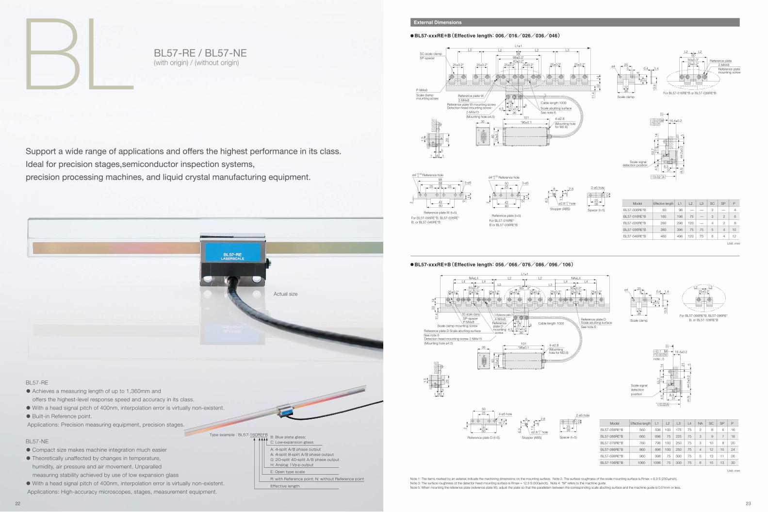
BL BL57-RE / BL57-NE(with origin) / (without origin)
External Dimensions
BL57-RE
• Achieves a measuring length of up to 1,360mm and
offers the highest-level response speed and accuracy in its class.
• With a head signal pitch of 400nm, interpolation error is virtually non-existent.
• Built-in Reference point.
Applications: Precision measuring equipment, precision stages.
BL57-NE
• Compact size makes machine integration much easier
• Theoretically unaffected by changes in temperature,
humidity, air pressure and air movement. Unparalled
measuring stability achieved by use of low expansion glass
• With a head signal pitch of 400nm, interpolation error is virtually non-existent.
Applications: High-accuracy microscopes, stages, measurement equipment.
Support a wide range of applications and offers the highest performance in its class.
Ideal for precision stages,semiconductor inspection systems,
precision processing machines, and liquid crystal manufacturing equipment.
Note 1: The items marked by an asterisk indicate the machining dimensions on the mounting surface. Note 2: The surface roughness of the scale mounting surface is Rmax = 6.3 S (250 μinch).Note 3: The surface roughness of the detector head mounting surface is Rmax = 12.5 S (500μinch). Note 4: "M" refers to the machine guide.Note 5: When mounting the reference plate (reference plate W), adjust the plate so that the parallelism between the corresponding scale abutting surface and the machine guide is 0.01mm or less.
Model
BL57-056RE*B
BL57-066RE*B
BL57-076RE*B
BL57-086RE*B
BL57-096RE*B
BL57-106RE*B
Effective length
560
660
760
860
960
1060
L1
596
696
796
896
996
1096
L2
100
75
100
100
75
75
L3
175
225
250
250
300
300
L4
75
75
75
75
75
75
NA
2
3
3
4
5
6
SC
8
9
10
12
13
15
SP
6
7
8
10
11
13
P
16
18
20
24
26
30
Unit: mm
Model
BL57-006RE*B
BL57-016RE*B
BL57-026RE*B
BL57-036RE*B
BL57-046RE*B
Effective length
60
160
260
360
460
L1
96
196
296
396
496
L2
—
75
120
75
120
L3
—
—
—
75
75
SC
2
3
4
5
6
SP
—
2
2
4
4
P
4
6
8
10
12
Unit: mm
BL57-xxxRE*B(Effective length: 006/016/026/036/046)
BL57-xxxRE*B(Effective length: 056/066/076/086/096/106)
4.5
(4.5
)8.3
5
53.7
1417
.8
21
44.2±0
.2
31
16.4±0.2
0.02 A
0.01 M0.01
Scale signal detection position
3825
10
2-ø5 hole
Spacer (t=5)
2.8
1.5
6
6.3
Stopper (ABS)
ø2.8+0.1 0 hole
5025
3-ø5
2 914
4260
For BL57-016RE*B or BL57-036RE*B
Reference plate (t=5)
Reference holeø4+0.05 0
5-ø5
2 9
14
25
4260
98
25 1588
For BL57-006RE*B, BL57-026RE*B, or BL57-046RE*B
Reference plate W (t=5)
Reference holeø4+0.05 0
ø4 25
4
21
13.8
16
38
0.4
12
5 1.4
Scale clamp
1.5
1 1
29
6
5
*33±
0.1
Scale abutting surface See note 6
P-M4x8
22
11.4
14
L1±1
2-M4x15
2-M4x8
L2L2 L3L3
27±0.2
36
92718
4.5
4-ø2.830
101
*96±0.1
40
(Mounting hole ø4.5)
(Mounting hole for M2.6)
Reference plate W mounting screwDetection head mounting screw
Scale clamp mounting screw
SC-scale clamp
Reference plate W
Cable length 1000
SP-spacer
25±0.2* 25±0.2*25±0.2* 25±0.2*
88±0.3*40±0.2*
98
25±0.2*25±0.2* 2-M4X8Reference plate
L2L2
Reference plate mounting screw
For BL57-016RE*B or BL57-036RE*B
50±0.3*60
25±0.2*
1.5
6 2.8
6.3
Stopper (ABS)
ø2.8 +0.1 0 hole
3825
10
2-ø5 hole
Spacer (t=5)
149
8
25
60
50
2
4-ø5 hole
Reference plate D (t=5)
44.2±0
.2
4.5
(4.5
)8.3
5
53.7
141
7.8
21
31
16.4±0.2
Scale signal detection position
* A
M0.02/2000.1
0.02
note : 5
ø4 25
4
21
13.8
16
38
0.4
12
5 1.4
Scale clamp
1.5
1 1
29
65
50±0.2*
*33±
0.1
40
Reference plate DScale abutting surfaceSee note 6
Reference plate D Scale abutting surfaceSee note 6
11.4
Detection head mounting screw 2-M4x15
1422
27±0.236
92718
4.5
4-ø2.830
101*96±0.1
NAxL4L4L4
L2
L3L3
NAxL4L4 L4
L2L1±1
P-M4x8
2-Reference plate D4-M4x8
SC-scale clamp
(Mounting hole ø4.5)
(Mounting hole for M2.6)
Scale clamp mounting screwCable length 1000
SP-spacerReference plate D mounting screw
50±0.3*25±0.2* 25±0.2*25±0.2*25±0.2*25±0.2*25±0.2*25±0.2*
50±0.3*25±0.2*
L2L2
For BL57-066RE*B, BL57-096RE*B, or BL57-106RE*B
25±0.2*
Type example : BL57-160REFB
Effective length
B: Blue plate glass;
C: Low-expansion glass
R: with Reference point; N: without Reference point
E: Open type scale
A: 4-split A/B phase output
A: 4-split 8-split A/B phase output
G: 20-split 40-split A/B phase output
H: Analog 1Vp-p output
22 23

External Dimensions External Dimensions
Note 1: The items marked by an asterisk indicate the machining dimensions on the mounting surface. Note 2: The surface roughness of the scale mounting surface is Rmax = 6.3 S (250μ inch).Note 3: The surface roughness of the detector head mounting surface is Rmax = 12.5 S (500μ inch). Note 4: "M" refers to the machine guide.Note 5: When mounting the reference plate (reference plate W), adjust the plate so that the parallelism between the corresponding scale abutting surface and the machine guide is 0.01mm or less.
Model
BL57-056NE*B
BL57-066NE*B
BL57-076NE*B
BL57-086NE*B
BL57-096NE*B
BL57-106NE*B
Effective length
560
660
760
860
960
1060
L1
596
696
796
896
996
1096
L2
100
75
100
100
75
75
L3
175
225
250
250
300
300
L4
75
75
75
75
75
75
NA
2
3
3
4
5
6
SC
8
9
10
12
13
15
SP
6
7
8
10
11
13
P
16
18
20
24
26
30
Unit: mm
Model
BL57-006NE*B
BL57-016NE*B
BL57-026NE*B
BL57-036NE*B
BL57-046NE*B
Effective length
60
160
260
360
460
L1
96
196
296
396
496
L2
—
75
120
75
120
L3
—
—
—
75
75
SC
2
3
4
5
6
SP
—
2
2
4
4
P
4
6
8
10
12
Unit: mm
BL57-xxxNE*B(Effective length: 006/016/026/036/046) BL57-xxxRE*C(Effective length: 003/006/011/016/021/026/031/036/041)
BL57-xxxNE*B(Effective length: 056/066/076/086/096/106)
1.5
6 2.8
6.3
Stopper (ABS)
holeø2.8 +0.05 0 38
25
10
2-ø5 hole
Spacer (t=5)
5-ø5
Reference hole
2 9
14
25
4260
98
25 1588
For BL57-006NE*B, BL57-026NE*B, or BL57-046NE*B
Reference plate W (t=5)
ø4 +0.05 0
5025
3-ø5
2 914
4260
For BL57-016NE*B or BL57-036NE*B
Reference plate W (t=5)
Reference holeø4 +0.05
0
16.4±0.2
48.7
18.2
514
21
Scale signal detection position 4.
6
40.5±0
.2
31 3.2
A0.01
0.01M* 0.01
*
ø4 25
4
21
13.8
16
38
0.4
12
5 1.4
Scale clamp
1.5
1 16
5
20.5
*33±
0.1
2-M2 x 12
Detection head mounting screw
See note 5
2211
.414
P-M4 x 8
L1±1
4-ø2.8
1813
30101
*96±0.1
40
2-M4 x 8
L2L2 L3L3
Cable length 300
(Mounting hole for M2.6)
Mounting hole
Reference plate W mounting screw
Scale clamp mounting screw
SC-scale clamp
Reference plate W
SP-spacer
Reference plate Scale abutting surface
88±0.3*40±0.2*
98
25±0.2* 25±0.2* 25±0.2*25±0.2*25±0.2*25±0.2* 2-M4x8
Reference plate
L2L2
Reference plate mounting screw
For BL57-016NE*B or BL57-036NE*B
50±0.3*
60
25±0.2*
8.3
5(3
.2)
31
16.4±0.2
40.5±0
.2
4.6
48.7
18.2
514
Scale signal detection position
21
0.01 A
M0.010.1
NOTE 5
3825
10
2-ø5 hole
Spacer (t=5)
149
8
25
60
50
2
4-ø5 hole
Reference plate W (t=5)
1.5
6 2.8
6.3
Stopper (ABS)
holeø2.8 +0.05 0
ø4 25
4
21
13.8
16
38
0.4
12
5 1.4
Scale clamp
L2L2
For BL57-066NE*B, BL57-096NE*B, or BL57-106NE*B
25±0.2*
1.5
1 1
20.5
6
5
*33±
0.1
Reference plate DScale abutting surfaceSee note 6
11.4
1422
NAxL4L4L4
L2
L3L3
NAxL4L4 L4
L2L1±1
40
*96±0.1101
30
1318 2-M2x12
Detection head mounting screw
P-M4x8
2-Reference plate D4-M4x8
SC-scale clamp
Mounting hole
Mounting hole
Reference plate D mounting screwScale clamp
mounting screw
Cable length 300
SP-spacer
4-ø2.8
25±0.2*25±0.2*25±0.2*25±0.2*25±0.2*25±0.2*25±0.2*25±0.2*50±0.3* 50 50±0.3*
Output signal form
Detection system
Grating pitch
Signal pitch
Thermal expansion coefficient
Main specifications [BL57-RE]
Model
Diffraction grating scanning system
30. 60. 110. 160. 210. 260. 310. 360. 410
Measuring length + 10mm (5mm on each side)
Measuring length + 36mm
60. 160. 260. 360. 460. 560. 660. 760. 860. 960. 1060
Measuring length +10mm (5mm on each side)
Measuring length + 36mm
1.6μm
0.4μm
Low expansion glass:-0.7x10⁻⁶/ ˚C • Blue plate glass:8x10⁻⁶/˚C
GF H
Measuring length(mm)
Maximum movable length
Entire scale length
Measuring length(mm)
Maximum movable length
Entire scale length
A/B quadrature output Analogue output
Differential (only zero pointoutput models are
compliant with EIA-422)Differential (compliant with EIA-422)Output signal
Scale length(Low expansion glass)
Scale length(Blue plate glass)
Resolution0.1/0.05μm(switchable)
0.02/0.01μm(switchable)
±0.5μm(30 to 170mm) / ±1.0μm(220 to 370mm) /±1.5μm(420mm or more)
0.4μm (1Vp-p)
1,500mm/s(0.1μm)650mm/s(0.05μm)
Minimum phase difference:38ns
300mm/s(0.02μm)120mm/s(0.01μm)
Minimum phase difference:38ns
3000mm/s
Max 7.5MHz
Accuracy (at 20˚C)
Maximum response speed
Note 1: There is a correlation between the maximum response speed and output cable length (the part beyond the interface box).Note 2: A power supply line longer than 10m is incompatible with EN61000-6-2. Take surge protection measures upon use.Note 3: Satisfy the required specifications at the connector input section.Note 4: Special models can support up to 3m. However, the maximum response speed is limited depending on the cable length.(In a 3m cable, the maximum response speed is two-thirds that of a 1m cable.)Note 5: Special models can support a measuring length of 1,070mm to 1,360mm.
User definable (within the range of effective length)
±0.4μm (depending on machine movement accuracy)
1m (Note 4)
When stationary : 10mm
+5V (±5%)
450mA (no load) 600mA (with 120 ohm termination)
100m/s2 (50 to 2000Hz)
200m/s2
0 to +40˚C(No condensation)
-10 to + 50˚C
Semiconductor laser with power of 4mW and wavelength of 790nm
JIS Class 1 equivalent, DHHS Class 1 equnivalent
Cable length
Bending radius
Alarm
Head cable
High impedance, alarm by output signalwhen maximum response speed is
exceeded or signal level error detected
15m Max (Note 2)(to the electronic control section) 15m Max(Note1) (Note 2)
3000
2330
1660
Unidirectional synchronous reference point (specify the position and detection direction)
Reference point output signal
Reference point position
Reference point accuracy (at 20˚C)
Output cable length
Power supply (Note 3)
Power consumption
Vibration resistance
Impact resistance
Operating temperature range
Storage temperature range
Light source
Radiation power
Model GF H
None
3
9
15
Cable length (m) Maximum response speed (mm/s)
Note 1: The items marked by an asterisk indicate the machining dimensions on the mounting surface. Note 2: The surface roughness of the scale mounting surface is Rmax = 6.3 S (250 μinch).Note 3: The surface roughness of the detector head mounting surface is Rmax = 12.5 S (500μinch). Note 4: "M" refers to the machine guide.Note 5: When mounting the reference plate (reference plate W), adjust the plate so that the parallelism between the corresponding scale abutting surface and the machine guide is 0.01mm or less.
Model
BL57-003RE*C
BL57-006RE*C
BL57-011RE*C
BL57-016RE*C
BL57-021RE*C
BL57-026RE*C
BL57-031RE*C
BL57-036RE*C
BL57-041RE*C
Effective length
30
60
110
160
210
260
310
360
410
L1
66
96
146
196
246
296
346
396
446
L2
—
—
50
75
100
120
120
75
100
L3
—
—
—
—
—
—
—
75
100
SC
1
2
3
3
3
4
4
5
5
SP
—
—
2
2
2
2
2
4
4
P
2
4
6
6
6
8
8
10
10
Unit: mm
Stopper (ABS)
1.5
6 2.8
6.3
hole+0.1 0ø2.811
.56.
5
5025
3-ø5
2 4260
For BL57-003RE*C, BL57-011RE*C, BL57-016RE*C, BL57-021RE*C,
BL57-036RE*C, or BL57-041RE*C
Reference plate W (t=2.2)
Reference holeø4 +0.05 0
10
25
2-ø5
38
Spacer (t=2.2)
ø41.45
11.3
13.512
18.5
0.3
38
25
4
Scale clamp
5-ø5
1.5
6.5
11.5
25
60
98
25 1588
42
For BL57-006RE*C, BL57-026RE*C, or BL57-031RE*C
Reference plate W (t=2.2)
Reference holeø4+0.05 0
1.5
1.7 1.7
29
2.3
4.6
*33±
0.1
Scale abutting surface See note 6
11.4
(Mounting hole ø”4.5)
L±1L3 L3L2 L2
11.5
23
2-M4x8P-M4x8
*27±0.236
92718
4.5
4-ø2.830
101*96±0.1
40
(Mounting hole for M2.6)
Reference plate W mounting screw Detection head mounting screw
Scale clamp mounting screw
Reference plate W
Cable length 1000
SP-spacer25±0.2* 25±0.2*
25±0.2*25±0.2*25±0.2*25±0.2*
88±0.3*98
40±0.2*SC-scale clamp Reference plate
2-M4X8
L2 L2
Reference plate mounting screw
For BL57-003RE*C, BL57-011RE*C, BL57-016RE*C, BL57-021RE*C, BL57-036RE*C, or BL57-041RE*C
6050±0.3*25±0.2*
42.7±0
.2
*
4.5
(4.5
)18
.5
52.2
11.5
18.4±0.2
18.8
5
8.331
*
0.01M0.01
A0.02
Scale signal detection position
24 25
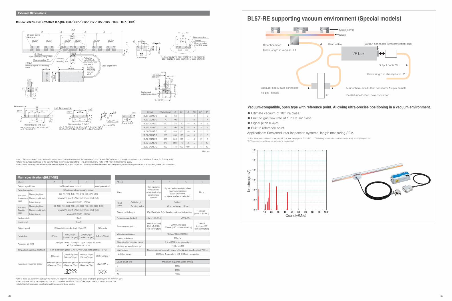
*1: For dimensions of head, scale, and I/F box, see the page on BL57-RE. *2: Cable length in vacuum and in atmosphere (L1 + L2) is up to 3m.*3: These components are not included in the product.
Vacuum-compatible, open type with reference point. Allowing ultra-precise positioning in a vacuum environment.
• Ultimate vacuum of 10-5 Pa class.
• Emitted gas flow rate of 10-6 Pa • m3 class.
• Signal pitch 0.4μm
• Built-in reference point.
Applications: Semiconductor inspection systems, length measuring SEM.
BL57-RE supporting vacuum environment (Special models)
1010-12
10-11
10-10
10-9
10-8
10-7
10-6
20 30 40 50 60 70 80 90 100
Scale clamp
Head cable Output connector (with protection cap)
I/F box
Output cable *3
Cable length in atmosphere: L2
Detection head
Cable length in vacuum: L1
Vacuum-side D-Sub connector
15-pin, female
Atmosphere-side D-Sub connector 15-pin, female
Sealed-side D-Sub male connector
Scale
Power source (Note 3)
Vibration resistance
Impact resistance
Operating temperature range
Storage temperature range
Light source
Radiation power
Model A
300min
When stationary: 10mm
100m/s2(50 to 2000Hz)
200m/s2
0 to +40˚C(no condensation)
-10 to + 50˚C
Semiconductor laser with power of 4mW and wavelength of 790nm
JIS Class 1 equivalent, DHHS Class 1 equivalent
Cable length
Bending radius
High-impedanceA/B quadrature
output signals whensignal level error
detected.
Alarm
Head cable
High-impedance output when maximum responsespeed exceeded
or signal level error detected.
15mMax (Note 2) (to the electronic control section)
F G H
None
15mMax (Note 1) (Note 2)
Power consumption
+5V (±5%)+5V (+10%-5%)
200 mA (no load)250 mA (9120
ohm termination)
290mA (no load)350mA (120 ohm termination)
250 mA (no load,120
ohm termination)
Output signal form
Detection system
Grating pitch
Signal pitch
Temperature expansion coefficient
Main specifications[BL57-NE]
Model
Diffraction grating scanning system
30. 70. 120. 170. 220. 270. 320. 370. 420
Measuring length +10mm (5mm on each side)
Measuring length + 26mm
60. 160. 260. 360. 460. 560. 660. 760. 860. 960. 1060
Measuring length +10mm (5mm on each side)
Measuring length + 36mm
1.6μm
0.4μm
Low expansion glass: -0.7 x 10⁻⁶/ ˚C • Blue plate glass:8 x 10⁻⁶/ ˚C
A
A/B quadrature output
F G
Analogue output
H
DifferentialDifferential (compliant with EIA-422)Output signal
Resolution
Maximum response speed
0.1μm0.1/0.05μm
(can be changed)0.02/0.01μm
(can be changed)
±0.5μm (30 to 170mm)/ ±1.0μm (220 to 370mm)/±1.5μm (420mm or more)
0.4μm (1Vp-p)
1,500mm/s (0.1μm)650mm/s(0.05μm)
300mm/s(0.02μm)120mm/s(0.01μm)
3000mm/s (Note 1)
Accuracy (at 20˚C)
1000mm/s
Measuring length(mm)
Maximum movable length
Entire scale length
Measuring length(mm)
Maximum movable length
Entire scale length
Scale length(Low expansion glass)
Scale length(Blue plate glass)
Minimum phasedifference:80ns
Max 7.5MHzMinimum phasedifference:38ns
Minimum phasedifference:38ns
Output cable length
Note 1: There is a correlation between the maximum response speed and output cable length (the part beyond the interface box).Note 2: A power supply line longer than 10m is incompatible with EN61000-6-2.Take surge protection measures upon use.Note 3: Satisfy the required specifications at the connector input section.
3000
2330
1660
3
9
15
Cable length (m) Maximum response speed (mm/s)
External Dimensions
Note 1: The items marked by an asterisk indicate the machining dimensions on the mounting surface. Note 2: The surface roughness of the scale mounting surface is Rmax = 6.3 S (250μ inch).Note 3: The surface roughness of the detector head mounting surface is Rmax = 12.5 S (500μ inch). Note 4: "M" refers to the machine guide.Note 5: When mounting the reference plate (reference plate W), adjust the plate so that the parallelism between the corresponding scale abutting surface and the machine guide is 0.01mm or less.
Model
BL57-003NE*C
BL57-007NE*C
BL57-012NE*C
BL57-017NE*C
BL57-022NE*C
BL57-027NE*C
BL57-032NE*C
BL57-037NE*C
BL57-042NE*C
Effective length
30
70
120
170
220
270
320
370
420
L1
56
96
146
196
246
296
346
396
446
L2
—
—
50
75
100
120
120
75
100
L3
—
—
—
—
—
—
—
75
100
SC
1
2
3
3
3
4
4
5
5
SP
—
—
2
2
2
2
2
4
4
P
2
4
6
6
6
8
8
10
10
Unit: mm
BL57-xxxNE*C(Effective length: 003/007/012/017/022/027/032/037/042) 1.
5
6.5
11.5
25
60
98
25 1588
42
For BL57-007NE*C, BL57-027NE*C, or BL57-032NE*C
Reference plate W (t=2.2)
Reference hole
ø4+0.05 0
5-ø5 Reference hole1.
5
6 2.8
6.3
Stopper (ABS)
holeø2.8+0.05 0
10
25
2-ø5
38Spacer (t=2.2)
Scale signal detection position
4.6
31 3.2
32.5±0
.218
.5
12.8
18.4±0.2
40.7
11.5
A0.01*
M*0.010.01
ø41.45
11.3
13.512
18.5
0.3
38
25
4
Scale clamp
1.5
1.7 1.72.3
4.6
20.5
*33±
0.1
2-M2x12
16.5
8
40
4-ø2.810130 *96±0.1
13
18
L1±1L3 L3L2 L2
11.5
2-M4x8
P-M4x8
(Mounting hole for M2.6)
Cable length 1000
Mounting hole
Reference plate W mounting screw
Scale clamp mounting screw
Reference plate WReference plate D Scale abutting surfaceSee note 5
SC-scale clampSP-spacer
25±0.2* 25±0.2* 25±0.2* 25±0.2* 25±0.2* 25±0.2*
88±0.3*98
40±0.2* Reference plate
2-M4x8
L2 L2
Reference plate mounting screw
For BL57-003NE*C, BL57-012NE*C, BL57-017NE*C, BL57-022NE*C, BL57-037NE*C, or BL57-042NE*C
6050±0.3*25±0.2*
11.56.5
5025
3-ø5
2
60
For BL57-003NE*C, BL57-012NE*C, BL57-017NE*C, BL57-022NE*C, BL57-037NE*C, or BL57-042NE*C
Reference plate W (t=2.2)
ø4+0.05 0
42
Ion
stre
ngth
(A)
Quantity (M/e)
26 27
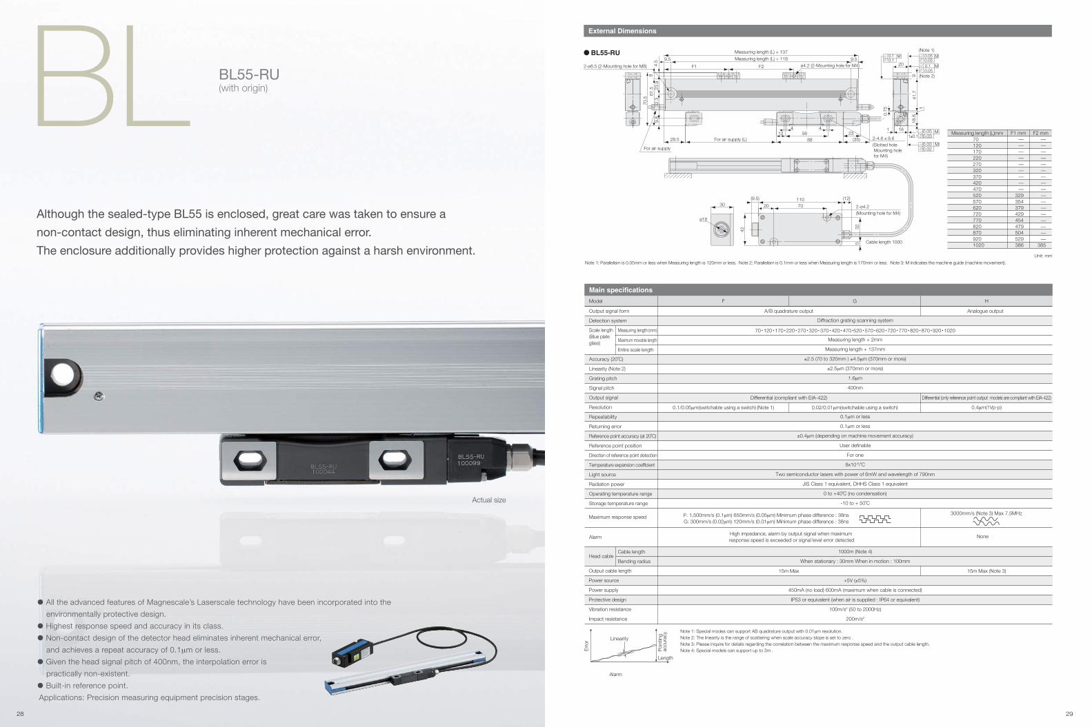
BL BL55-RU(with origin)
External Dimensions
Actual size
• All the advanced features of Magnescale’s Laserscale technology have been incorporated into the
environmentally protective design.
• Highest response speed and accuracy in its class.
• Non-contact design of the detector head eliminates inherent mechanical error,
and achieves a repeat accuracy of 0.1μm or less.
• Given the head signal pitch of 400nm, the interpolation error is
practically non-existent.
• Built-in reference point.
Applications: Precision measuring equipment precision stages.
Note 1: Parallelism is 0.05mm or less when Measuring length is 120mm or less. Note 2: Parallelism is 0.1mm or less when Measuring length is 170mm or less. Note 3: M indicates the machine guide (machine movement).
Although the sealed-type BL55 is enclosed, great care was taken to ensure a
non-contact design, thus eliminating inherent mechanical error.
The enclosure additionally provides higher protection against a harsh environment.Unit: mm
Measuring length (L)mm701201702202703203704204705205706207207708208709201020
F1 mm—————————
329354379429454479504529386
F2 mm—————————————————
385
BL55-RU
1
1±0.1
9.8
70.5
61.5
4.5
23.9
20
41.7
For air supply
44
F2F1
For air supply (L)28.5
Measuring length (L) + 137
Measuring length (L) + 118
(12)
(35)23
8812
0.75
18.8
1
18
2-ø8.5 (2-Mounting hole for M8)
2-ø4.2(Mounting hole for M4)
2-4.6 x 8.6 (Slotted hole Mounting hole for M4)
702030
ø18
42
32
(9.5) 110
56
Cable length 1000
9.5
32.3
9.5
9
5
9 (Note 2)
(Note 1)M
0.050.05
M0.020.03
M0.030.05
M0.10.1
M0.050.1ø4.2 (2-Mounting hole for M4)
Diffraction grating scanning system
Measuring length + 2mm
Measuring length + 137mm
±2.5 (70 to 320mm ) ±4.5μm (370mm or more)
±2.5μm (370mm or more)
1.6μm
400nm
0.1μm or less
0.1μm or less
±0.4μm (depending on machine movement accuracy)
User definable
For one
8x10⁻⁶/˚C
Two semiconductor lasers with power of 6mW and wavelength of 790nm
JIS Class 1 equivalent, DHHS Class 1 equivalent
0 to +40˚C (no condensation)
-10 to + 50˚C
Output signal form
Detection system
Accuracy (20˚C)
Linearity (Note 2)
Grating pitch
Signal pitch
Output signal
Resolution
Repeatability
Returning error
Reference point accuracy (at 20˚C)
Reference point position
Direction of reference point detection
Temperature expansion coefficient
Light source
Radiation power
Operating temperature range
Storage temperature range
Alarm
Main specifications
Model F G
Output cable length
Power source
Power supply
Protective design
Vibration resistance
Impact resistance
Cable length
Bending radiusHead cable
15m Max
Alarm
High impedance, alarm by output signal when maximum response speed is exceeded or signal level error detected
None
15m Max (Note 3)
Maximum movable length
Entire scale length
A/B quadrature output
H
Analogue output
Differential (only reference point output models are compliant with EIA-422)
0.4μm(1Vp-p)
Differential (compliant with EIA-422)
0.1/0.05μm(switchable using a switch) (Note 1) 0.02/0.01μm(switchable using a switch)
Measuring length (mm)
Maximum response speed F: 1,500mm/s (0.1μm) 650mm/s (0.05μm) Minimum phase difference : 38nsG: 300mm/s (0.02μm) 120mm/s (0.01μm) Minimum phase difference : 38ns
3000mm/s (Note 3) Max 7.5MHz
70 • 120 • 170 • 220 • 270 • 320 • 370 • 420 • 470 •520 • 570 • 620 • 720 • 770 • 820 • 870 • 920 • 1020Scale length(Blue plate glass)
Poi
ntin
g ac
cura
cy
Linearity
Length
Err
or
Note 1: Special modes can support AB quadrature output with 0.01μm resolution.Note 2: The linearity is the range of scattering when scale accuracy slope is set to zero .Note 3: Please inquire for details regarding the correlation between the maximum response speed and the output cable length .Note 4: Special models can support up to 3m .
1000m (Note 4)
When stationary : 30mm When in motion : 100mm
+5V (±5%)
450mA (no load) 600mA (maximum when cable is connected)
IP53 or equivalent (when air is supplied : IP64 or equivalent)
100m/s2 (50 to 2000Hz)
200m/s2
28 29

BD BD96Interpolator for Laserscale TM
External Dimensions
Maximum resolution of 17pm when combined with the BS series.
Supporting various serial and binary outputs.
• Maximum resolution :
0.4nm (When connected with BL series)
31pm (When connected with BH series)
17pm (When connected with BS series)
• High response speed :
1,100mm/s (When connected with BL series)
700mm/s (When connected with BH series)
400mm/s (When connected with BS series)
• Various serial or binary outputs
• Includes automatic signal compensation
• AB quadrature output
(standard : 4 divisions) (binary output axis 1 or 2 type)
BS series : 34.5nm, BH series : 62.5nm, BL series : 100nm
• Maximum no. of divisions : 8000 (When connected with BS and BH series)
* Please inquire about various specifications, such as the number of divisions.
DC +5V : 0.4A DC +12V : 0.7A DC -12V : 0.5A ( 2 axes type )Current Consumption ( When scale is connected )
0.4nm (When connected with BL series),0.03125nm (When connected with BH series),0.017nm (When connected with BS series)
400mm/s (When connected with BS series),700mm/s (When connected with BH series),1,100mm/s (When connected with BL series)
025 : 256, 051 : 512, 040 : 400, 050 : 500, 100 : 1000, 200 : 2000, 400 : 4000, 800 : 8000
When exceeding the maximum response speed or when the laser signal level is too low (disconnection ); LED lights up
DC offset, amplitude, phase
DC +5V±5% DC +12V±5% DC -12V±5%
0 to +40˚C
-10 to +50˚C
236 (W) x 215.2 (D) x 48 (H)mm
Approx. 1.6kg
Main specifications
Model BD 96
MAX. resolution
Response speed
MAX. division
Alarm
Input signal compensation
Power supply
Operating temperature range
Storage temperature range
Dimensions
Weight
Output mode B: Binary (Axis type 1 or J : 40 bits, 2 : 20bits) Y: Yaskawa Electric serial M: Mitsubishi Electric serial F: FANUC*2 serial*2 Special model
Axis type 1: 1 axis 2: 2 axes J: Supports long scales of the BLseries (Max. 512 divisions)
Division 025: 256 divisions 051: 512 divisions 040: 400 divisions 050: 500 divisions 100: 1000 divisions 200: 2000 divisions 400: 4000 divisions 800: 8000 divisions
Scale type S: BS series H: BH series L: BL series
Shape C: Case type
48
●BD96-Y1/M1
●BD96-B1
24
Base (opposite side)4-M3 Tap (for mounting)
6-M3 Tap (for mounting)(both sides)
28180(28)
200
(15.
2)18
0
25
10
11.5
10
180
(10)
236
(15.
2)
(10)25 11.5
24
180
10(1
0)
200
Base (opposite side)4-M3 Tap (for mounting)
180
6-M3 Tap (for mounting)(both sides)
1028180(28)
236
3
1 12
●BD96-B2
24
Base (opposite side)4-M3 Tap (for mounting)
6-M3 Tap (for mounting)(both sides)
28180(28)
200
(15.
2)18
0
25
10
11.5
10
180
(10)
236
48
3
1 12
48
3
1
SENSOR 1SERIAL 1
●BD96-Y2/M2
(15.
2)
(10)25 11.5
24
180
10(1
0)
200
Base (opposite side)4-M3 Tap (for mounting)
180
6-M3 Tap (for mounting)(both sides)
1028180(28)
236
48
3
1
SERIAL 1 SENSOR 2 SENSOR 1SERIAL 2
HEAD IN 2 HEAD IN 1
Unit: mm
*2 External dimensions of the 1- and 2-axis are identical.
30 31
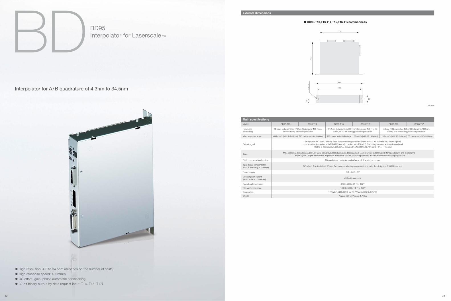
BD BD95Interpolator for Laserscale TM
External Dimensions
• High resolution: 4.3 to 34.5nm (depends on the number of splits)
• High response speed: 400mm/s
• DC offset, gain, phase automatic conditioning
• 32 bit binary output by data request input (T14, T16, T17)
Unit: mm
Interpolator for A/B quadrature of 4.3nm to 34.5nm
Resolution(selectable)
Main specifications
Model BD95-T13 BD95-T14 BD95-T16 BD95-T10BD95-T15 BD95-T17
Power supply
Operating temperature
Storage temperature
Dimensions
Weight
Input signal compensation (On/Off switching is possible)
Consumption current (when scale is connected)
Alarm
DC + 24V ± 1V
0˚C to 50˚C / 32˚ F to 122˚F
-10˚C to 60˚C / 14˚ F to 140˚F
172 (W)x144(D)x32(H) mm/6.77”(W)x5.66”(D)x1.25”(H)
Approx. 0.8 kg/Approx.1.76Ibs
AB quadrature 1 only A round-off error of 1 resolution occurs.
DC offset, Amplitude level, Phase. Frequencies allowing compensation update: Input signals of 180 kHz or less
34.5 nm (4divisions) or 17.2nm (8 divisions) 100 nm or50 nm during pitchcompensation
17.2 nm (8divisions) or 8.6 nm(16 divisions) 100 nm, 5050nm, or 10 nm during pitch compensation
8.6 nm (16divisions) or 4.3 nm(32 divisions) 100 nm,50nm, or 5 nm during pitch compensation
Max. response speed exceeded Low laser signal level(cable broken or disconnected) LEDs (Turn on independently for speed alarm and level alarm) Output signal: Output when either a speed or level alarm occurs. Switching between automatic reset and holding is possible
AB quadrature 1 with / without pitch compensation (compliant with EIA-422) AB quadrature 2 without pitchcompensation (compliant with EIA-422) Alarm (compliant with EIA-422) (Switching between automatic reset and
holding is possible) LASERSCALE signal (SIN/COS) 32-bit binary data (-T14, -T16 only)
Max. response speed
Output signal
Pitch compensation function
275 mm/s (with 8 divisions) 120 mm/s (with 16 divisions) 120 mm/s (with 16 divisions) 60 mm/s (with 32 divisions)400 mm/s (with 4 divisions) 275 mm/s (with 8 divisions)
400mA (maximum)
172
144
200
2-R
2.2
16
32
190
BD95-T10,T13,T14,T15,T16,T17commonness
32 33

TechnologyBefore use
Upside
Downside
or
Mounting Direction BL55-RU
Please see the diagram blow about an instrallation method of Laserscale.
SliderThe slider has a built-in detector head. The slider is secured in place by the slider holders at shipping.
Scale unitThe scale unit incorporates a high-accuracy LASERSCALE. It is protected by an aluminum cover.
Foot plateThis is used to secure the scale in place.
The number of attached foot plates varies depending on the scale measuring length.
Measuring length of 470 mm or less ........................ none
Measuring length of 520 mm to 920 mm ................... 1
Measuring length of 1020 mm .................................. 2
Air inletThis is used when air is injected. To inject air, remove the hex.socket-head set screws covering the inlets, and then attach the hex. sockethead half-union.
Scale
A
OK
Checking the Installation Direction
Check that the scale is installed in the positional relationship
shown in Fig. 3-1.
Except when installed on a vertical axis, only the orientation in Fig.
3-1 should be used.
[Note]
If installing on a machine tool or other equipment where powder and dust occur, install using the A orientation
since this allows usage of cutting fluid and prevents the intrusion of cutting dust.
Install using the B orientation only in other situations when virtually no foreign objects can enter the scale.
B
Conditional
BL55RUxxxxxxx
Slider1 Connector6
Model name and Serial No.5
Scale unit2
Air inlet4
Foot plate3
1
2
3
4
Connection Cable Scales
Extension Cable*2 InterpolatorModel Head cable length*1
3m (Standard)
1m (Standard)
1m (Standard)
BD95
BD96
Robot cable:CK-T133 (0.1m) CK-T137 (3.0m) CK-T112 (5.0m)
Robot cable:CK-T148 (3.0m)
Robot cable:CE20-03T10 (3.0m) CE20-06T01 (6.0m) CK-T144 (9.0m)
Robot cable:CK-T61 (1.0m) CK-T24 (3.0m) CK-T54 (6.0m)
BS78BS65-R
BH20-NE
BH25-REDBH20-REDBL57-RED
ScalesExtension Cable Interpolator
Model Head cable length*1
1m (Standard)
0.3m (Standard)
1m (Standard)
0.3m (Standard)
1m (Standard)
Built-in I/FBox
Robot cable:CE20-03T07 (3.0m) CE20-05T05 (5.0m)
Robot cable:CE20-07T03 (7.0m)
Robot cable:CE20-03 (3.0m) CE20-05 (5.0m) CE20-07 (7.0m)
BL55-RU
BL57-NE(A/B phase)
BL57-RE(A/B phase)
BL57-NE(Analog)
BL57-RE(Analog)
*1 Please ask for other length. *2 can lengthen to max. 9m. Please ask for more than 9m.
*1 Please ask for other length. The robot cable minimum bend radius: R80mm is fixed repeatedly R10mm.
Upside
Downside
*Please refer to page 39 for an electric supply.
34 35
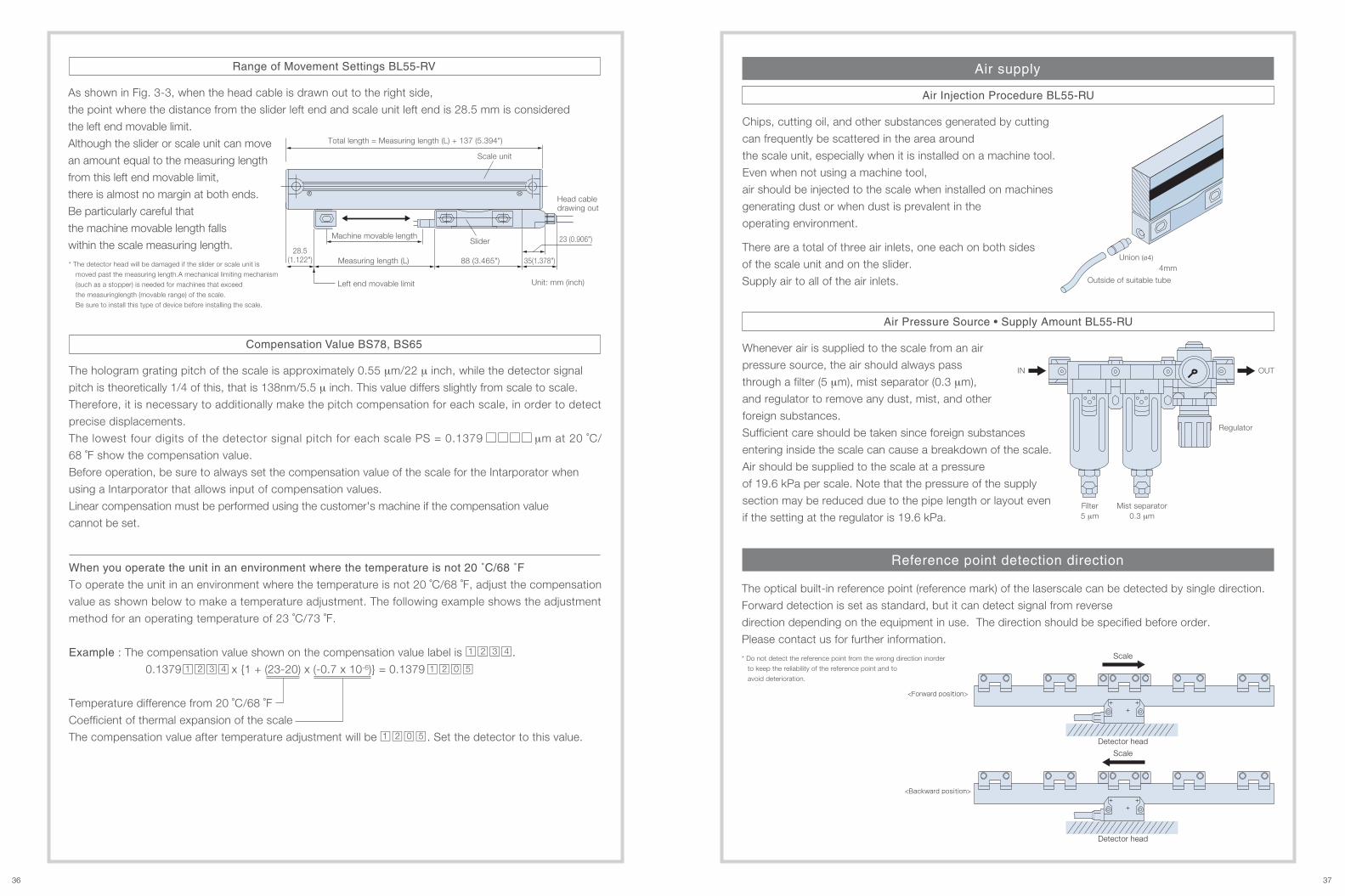
The optical built-in reference point (reference mark) of the laserscale can be detected by single direction.
Forward detection is set as standard, but it can detect signal from reverse
direction depending on the equipment in use. The direction should be specified before order.
Please contact us for further information.
Reference point detection direction
Air supply
<Forward position>
Scale
Detector head
<Backward position>
Scale
Detector head
* Do not detect the reference point from the wrong direction inorder
to keep the reliability of the reference point and to
avoid deterioration.
Union (ø4)
Outside of suitable tube
Regulator
Mist separator0.3 μm
Filter5 μm
4mm
Unit: mm (inch)
Slider
Scale unit
Machine movable length
Left end movable limit
Measuring length (L)
Total length = Measuring length (L) + 137 (5.394")
Head cable drawing out
28.5(1.122") 88 (3.465") 35(1.378")
IN OUT
Range of Movement Settings BL55-RV
As shown in Fig. 3-3, when the head cable is drawn out to the right side,
the point where the distance from the slider left end and scale unit left end is 28.5 mm is considered
the left end movable limit.
Although the slider or scale unit can move
an amount equal to the measuring length
from this left end movable limit,
there is almost no margin at both ends.
Be particularly careful that
the machine movable length falls
within the scale measuring length.
Air Injection Procedure BL55-RU
Chips, cutting oil, and other substances generated by cutting
can frequently be scattered in the area around
the scale unit, especially when it is installed on a machine tool.
Even when not using a machine tool,
air should be injected to the scale when installed on machines
generating dust or when dust is prevalent in the
operating environment.
Air Pressure Source • Supply Amount BL55-RU
Whenever air is supplied to the scale from an air
pressure source, the air should always pass
through a filter (5 μm), mist separator (0.3 μm),
and regulator to remove any dust, mist, and other
foreign substances.
Sufficient care should be taken since foreign substances
entering inside the scale can cause a breakdown of the scale.
Air should be supplied to the scale at a pressure
of 19.6 kPa per scale. Note that the pressure of the supply
section may be reduced due to the pipe length or layout even
if the setting at the regulator is 19.6 kPa.
Compensation Value BS78, BS65
The hologram grating pitch of the scale is approximately 0.55 μm/22 μ inch, while the detector signal
pitch is theoretically 1/4 of this, that is 138nm/5.5 μ inch. This value differs slightly from scale to scale.
Therefore, it is necessary to additionally make the pitch compensation for each scale, in order to detect
precise displacements.
The lowest four digits of the detector signal pitch for each scale PS = 0.1379 μm at 20 ˚C/
68 ˚F show the compensation value.
Before operation, be sure to always set the compensation value of the scale for the Intarporator when
using a Intarporator that allows input of compensation values.
Linear compensation must be performed using the customer's machine if the compensation value
cannot be set.
23 (0.906")
When you operate the unit in an environment where the temperature is not 20 ˚C/68 ˚F
To operate the unit in an environment where the temperature is not 20 ˚C/68 ˚F, adjust the compensation
value as shown below to make a temperature adjustment. The following example shows the adjustment
method for an operating temperature of 23 ˚C/73 ˚F.
Example : The compensation value shown on the compensation value label is .
0.1379 x {1 + (23-20) x (-0.7 x 10⁻⁶)} = 0.1379
Temperature difference from 20 ˚C/68 ˚F
Coefficient of thermal expansion of the scale
The compensation value after temperature adjustment will be . Set the detector to this value.
1 2 3 4
1 2 3 4 1 2 0 5
1 2 0 5
There are a total of three air inlets, one each on both sides
of the scale unit and on the slider.
Supply air to all of the air inlets.
* The detector head will be damaged if the slider or scale unit is
moved past the measuring length.A mechanical limiting mechanism
(such as a stopper) is needed for machines that exceed
the measuringlength (movable range) of the scale.
Be sure to install this type of device before installing the scale.
36 37
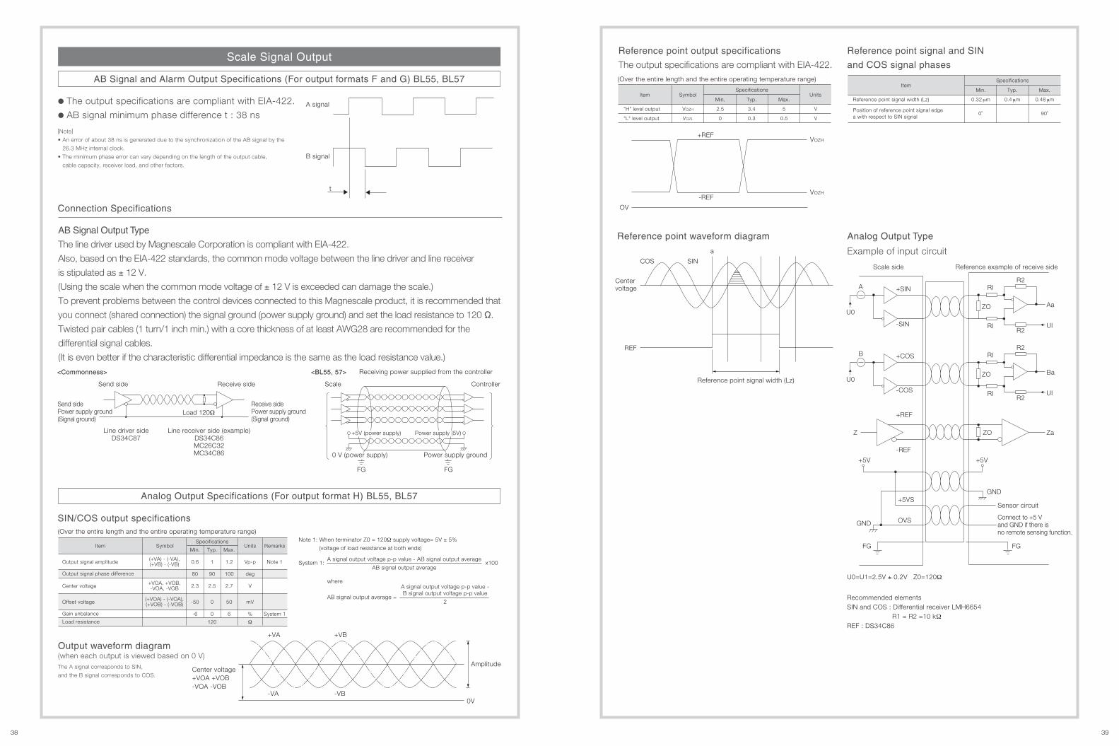
AB Signal Output Type
The line driver used by Magnescale Corporation is compliant with EIA-422.
Also, based on the EIA-422 standards, the common mode voltage between the line driver and line receiver
is stipulated as ± 12 V.
(Using the scale when the common mode voltage of ± 12 V is exceeded can damage the scale.)
To prevent problems between the control devices connected to this Magnescale product, it is recommended that
you connect (shared connection) the signal ground (power supply ground) and set the load resistance to 120 Ω.
Twisted pair cables (1 turn/1 inch min.) with a core thickness of at least AWG28 are recommended for the
differential signal cables.
(It is even better if the characteristic differential impedance is the same as the load resistance value.)
SIN/COS output specifications
A signal
B signal
t
Output waveform diagram (when each output is viewed based on 0 V)The A signal corresponds to SIN,
and the B signal corresponds to COS.
Reference point output specifications
The output specifications are compliant with EIA-422.
Reference point waveform diagram Analog Output Type
Example of input circuit
Scale side Reference example of receive side
Sensor circuit
Connect to +5 V and GND if there isno remote sensing function.
U0=U1=2.5V ± 0.2V Z0=120Ω
Recommended elementsSIN and COS : Differential receiver LMH6654 R1 = R2 =10 kΩREF : DS34C86
+REF
-REF
VOZH
OV
VOZH
(Over the entire length and the entire operating temperature range)
(Over the entire length and the entire operating temperature range)
Item Symbol Units
"H" level output
"L" level output
VOZH
VOZL
V
V
Specifications
Min.
2.5
0
Typ.
3.4
0.3
Max.
5
0.5
Reference point signal and SIN
and COS signal phases
ZaZ
Scale Signal Output
Gain unbalance
Load resistance
Units RemarksSpecifications
Item
Output signal amplitude
Output signal phase difference
Symbol
(+VA) - (-VA),(+VB) - (-VB)
(+VOA) - (-VOA),(+VOB) - (-VOB)
+VOA, +VOB,-VOA, -VOBCenter voltage
Offset voltage
Min. Typ. Max.
0.6
80
2.3
-50
-6
1
90
2.5
0
0
120
Vp-p
deg
V
mV
%
Ω
1.2
100
2.7
50
6 System 1
Note 1
COS SIN
A
B
U0
U0Receiving power supplied from the controller
+VA
-VA
+VB
-VB0V
AmplitudeCenter voltage+VOA +VOB-VOA -VOB
+SIN
-SIN
+COS
-COS
+REF
-REF
+5VS
OVS
+5V+5V
GND
GND
FG FG
ZO
RIR2
R2RI UI
Aa
ZO
RIR2
R2RI UI
Ba
ZO
Centervoltage
Reference point signal width (Lz)
REF
a
Send side
Send sidePower supply ground(Signal ground)
Receive side
Receive sidePower supply ground(Signal ground)
Line receiver side (example)DS34C86MC26C32MC34C86
Line driver sideDS34C87
Load 120Ω
AB Signal and Alarm Output Specifications (For output formats F and G) BL55, BL57
Analog Output Specifications (For output format H) BL55, BL57
Connection Specifications
• The output specifications are compliant with EIA-422.
• AB signal minimum phase difference t : 38 ns
[Note]
• An error of about 38 ns is generated due to the synchronization of the AB signal by the
26.3 MHz internal clock.
• The minimum phase error can vary depending on the length of the output cable,
cable capacity, receiver load, and other factors.
Scale Controller
FG FG
+5V (power supply) Power supply (5V)
Power supply ground0 V (power supply)
Note 1: When terminator Z0 = 120Ω supply voltage= 5V ± 5%
(voltage of load resistance at both ends)
where
AB signal output average =
A signal output voltage p-p value -B signal output voltage p-p value
2
System 1:A signal output voltage p-p value - AB signal output average
AB signal output averagex100
Item
Position of reference point signal edgea with respect to SIN signal
Specifications
Min.
0.32 μm
Typ.
0.4 μm
Max.
0.48 μmReference point signal width (Lz)
0˚ 90˚
<Commonness> <BL55, 57>
38 39

40 41
Connectors (Open type) BL57-RE, BL57NE
A/B signal output Analog output
A
B
C
D
E
F
G
H
J
K
L
M
Pin arrangement
A
*A
B
*B
Z
*Z
+5 V (power supply)
0 V (power supply)
0 V (signal)
0 V (signal)
+5 VS
0 VS
A/B signal output
+COS
-COS
+SIN
-SIN
+REF
-REF
Analog output
Input/output specifications
1
2
3
4
5
6
7
8
9
10
11
12
13
14
15
16
17
18
19
20
21
22
23
24
25
26
Pin arrangement
A
*A
B
*B
REF
*REF
+5 V (power supply)
ALM
+5 V (power supply)
*ALM
+5VS
(Not connectable)
+5 V (power supply)
SIN (M)
0 V (power supply)
COS (M)
0 V (power supply)
(Not connectable)
0VS
(Not connectable)
0V (M)
(Not connectable)
0 V (power supply)
(Not connectable)
0 V (signal)
(Not connectable)
A/B signal output(Output format F, G)
+COS
-COS
+SIN
-SIN
(Not connectable)
0 V (power supply)
0VS
(Not connectable)
+5 V (power supply)
+5VS
+REF
-REF
(Not connectable)
(Not connectable)
(Not connectable)
Analog output(Output format H)
Input/output specifications
[Note]
• 0 V is the circuit ground, and it is not connected to the frame ground.
• Make sure that the power supply voltage is 5 V DC ± 5 % at the input connector to the interface unit.
• +5 V S and 0 V S are for checking the voltage (remote sensing function) applied to the input connector of the interface unit.
These voltages can be used to check and control for drops in the supply voltage due to the cables.
When using a power supply that cannot control power supply fluctuations,
a power supply input terminal can be used to reduce the supply voltage drops occurring due to the cable length.
In this case, connect the cable to the respective +5 V or 0 V power supply.
• The appropriate cable thickness is AWG28 to AWG24.
• Connect all of the 0 V terminals to prevent mis-wiring.
• Use shielded cables for all cabling.
• Use twisted-pair cables for the output signals.
Use cables so that the following signals are paired: A and *A, B and *B, Z and *Z, +SIN and -SiN, +COS and -COS, +REF and -REF.
Input/Output Connectors
Connectors BL55
Interface unit side : R04-R12M (manufactured by TAJIMI ELECTRONICS CO., LTD.)
Cable side : R04-P12F (manufactured by TAJIMI ELECTRONICS CO., LTD.) ....... Waterproof type
R03-PB12F (manufactured by TAJIMI ELECTRONICS CO., LTD.) ..... Non-waterproof type
Interface unit side:A/B signal output : 10226-52A2JL
(manufactured by SUMITOMO 3M Limited)
Analog output : D02-M15SAG-26L9
(manufactured by Japan Aviation Electronics Industry, Limited)
Cable side:A/B signal output : Plug 10126-3000VE
(manufactured by SUMITOMO 3M Limited)
: Shell 10326-52F0-00S
(manufactured by SUMITOMO 3M Limited)
Analog output : Plug D02-M15PG-N-F0
(manufactured by Japan Aviation Electronics Industry, Limited)
: Contact When AWG24 wire is used
D02-22-22P-PKG100
(manufactured by Japan Aviation Electronics Industry, Limited)
: Contact When AWG26-28 wire is used
D02-22-26P-PKG100
(manufactured by Japan Aviation Electronics Industry, Limited)
: Shell DE-C8-J9-F2-1
(manufactured by Japan Aviation Electronics Industry, Limited)

http://www.mgscale.com
42 43