Embed Size (px)
DESCRIPTION
MANUAL BOILER DE DEPOSITO INDUSTRIAL A GAS LP ULTRA EFICIENTE 95% REDUCE COSTOS LINEA SPIDERfire
Citation preview

Printed in USA
FOR YOUR SAFETY!
— Do not store or use gasoline or other flammable vapors or liquids or other combustible materials in the vicinity of this or any other appliance. To do so may result in an explosion or fire.
— WhAT TO DO iF YOU SmEll gAS
• Do not try to light any appliance.
• Do not touch any electrical switch; do not use any phone in your building.
• immediately call your gas supplier from a neighbor's phone. Follow the gas supplier's instructions.
• if you cannot reach your gas supplier, call the fire department.
• Do not return to your building until authorized by the gas supplier or fire department.
— improper installation, adjustment, alteration, service or maintenance can cause injury, property dam-age or death. Refer to this manual. installation and service must be performed by a qualified installer, service agency or the gas supplier.
WARNiNg: if the information in these instructions are not followed exactly, a fire or explosion may result causing property damage, personal injury or death.
NOTiCE: This water heater is designed for use in a commercial application and the installation and maintenance of it should be per-formed by a qualified, licensed service personnel. if the foregoing assumption is not appropriate, then we recommend that you obtain and retain our Residential Use & Care manual.
!
!
!
AP14729-1(10/09)
WiTh iNSTAllATiON iNSTRUCTiONS FOR ThE CONTRACTOR
Commercial high Efficiency Water heater
USE & CARE mANUAl
CAliFORNiA PROPOSiTiON 65 WARNiNg: This product contains chemicals known to the State of California to cause cancer, birth defects or other reproductive harm.!
Do Not Destroy this manual. Please read carefully and keep in a safe place for Future Reference.
Recognize this symbol as an indication of important Safety information! ! !
DESIGN
CERTIFIED ®
Safety Information
Safety Precautions . . . . . . . . . . . . . . . . . . .3-4
Introduction
local installation Regulations . . . . . . . . . . 5
Water heater location . . . . . . . . . . . . . . . . . 5
Installation Instructions
inspect Shipment . . . . . . . . . . . . . . . . . . . . . 5
Water Supply Connections . . . . . . . . . . . . . 6
gas Supply . . . . . . . . . . . . . . . . . . . . . . . . . . 6
Wiring . . . . . . . . . . . . . . . . . . . . . . . . . . . . . . . 7
Typical installation . . . . . . . . . . . . . . . . . . . . 8
Vent installation . . . . . . . . . . . . . . . . . . . .9-21
installation Checklist . . . . . . . . . . . . . . . . . 22
TABlE OF CONTENTS
Your safety and the safety of others are very impor-tant. There are many important safety messages in this manual and on your appliance. Always read and obey all safety messages.
!This is the safety alert symbol. Recognize this symbol as an indication of Important Safety Information! This sym-bol alerts you to potential hazards that can kill or hurt you and others.
All safety messages will follow the safety alert sym-bol and either the word “DANgER”, “WARNiNg”, “CAUTiON” or “NOTiCE”.
These words mean:
! DANgER An imminently hazardous situation that will result in death or serious injury.
! WARNiNg A potentially hazardous situ-ation that could result in death or serious injury and/or damage to property.
! CAUTiON A potentially hazardous situ-ation that may result in minor or moderate injury.
Notice: Attention is called to observe a specified procedure or maintain a specific condition.
READ THE SAFETY INFORMATION
2
Operating Instructions
lighting instructions . . . . . . . . . . . . . . . . . 23
Water Temperature . . . . . . . . . . . . . . . . . . . 24
Emergency Shut Down . . . . . . . . . . . . . . . 24
User interface . . . . . . . . . . . . . . . . . . . . .25-26
Troubleshooting
Before You Call For Service . . . . . . . . 28- 29
Customer Service
Parts list . . . . . . . . . . . . . . . . . . . . . . . . . . . 30
Wiring Diagrams . . . . . . . . . . . . . . . . . . . . . . 31
how to Obtain Service Assistance . . . . . 32
Care and Cleaning
Pressure Switch inspection . . . . . . . . . . . 27
Venting inspection . . . . . . . . . . . . . . . . . . . 27
Routine Maintenance . . . . . . . . . . . . . . . . . . 27
Anode inspection . . . . . . . . . . . . . . . . . . . . 27
Seasonal Operation . . . . . . . . . . . . . . . . . . 27

3
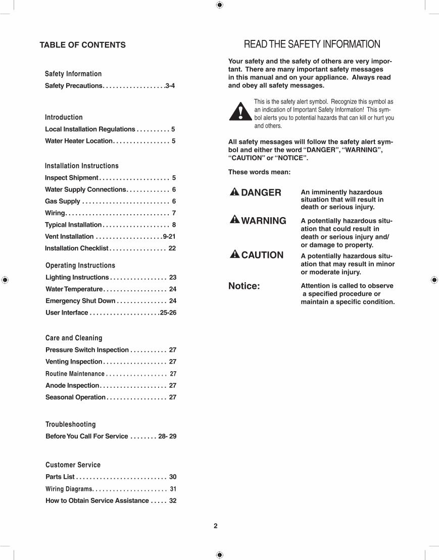
To meet commercial water use needs, the temperature on this water heater is adjustable up to 185°F (85° C). however, water tem-peratures over 125°F (52° C) can cause severe burns instantly or death from scalds. This is the preferred starting point for setting the control for supplying general purpose hot water.
Safety and energy conservation are factors to be considered when setting the water temperature. The most energy efficient operation will result when the temperature setting is the lowest that satisfies the needs consistent with the application.maximum water temperatures occur just after burner has shut off.
To find hot water temperature being delivered, turn on a hot water faucet and place a thermometer in the hot water stream and read the thermometer.
general Safety Precautions!The following chart details the relationship of water temperature and time with regard to scald injury and may be used as a guide in determining the safest water temperature for your applications.
The temperature of the water in the heater can be regulated by setting the temperature on the display (see pages 18 & 19). To comply with safety regulations the temperature was set at 120°F before water heater was shipped from the factory. The illustra-tion information on pages 25 & 26 shows the Display and how to adjust the water temperature.
hotter water increases the Potential for hot Water SCAlDS.
NOTiCE: mixing valves are available for reducing point of use water temperature by mixing hot and cold water in branch water lines. Contact a licensed plumber or the local plumbing authority for further information.
D A N G E R!
HOT
Water temperature over 125°F cancause severe burns instantly ordeath from scalds.
Children, disabled and elderly areat highest risk of being scalded.
See instruction manual beforesetting temperature at waterheater.Feel water before bathing orshowering.Temperature limiting valves areavailable, see manual.
BURN
Temperature Time to Produce Serious Burn 120° F (49°C) More than 5 minutes 125° F (52°C) 11/2 to 2 minutes 130° F (54°C) About 30 seconds 135° F (57°C) About 10 seconds 140° F (60°C) Less than 5 seconds 145° F (63°C) Less than 3 seconds 150° F (66°C) About 11/2 seconds 155° F (68°C) About 1 second
Table courtesy of Shriners Burn Institute
TimE / TEmPERATURE RElATiONShiPS iN SCAlDS
DANGER!
See Section "User interface" (pages 25 & 26) for setting the temperature.
4
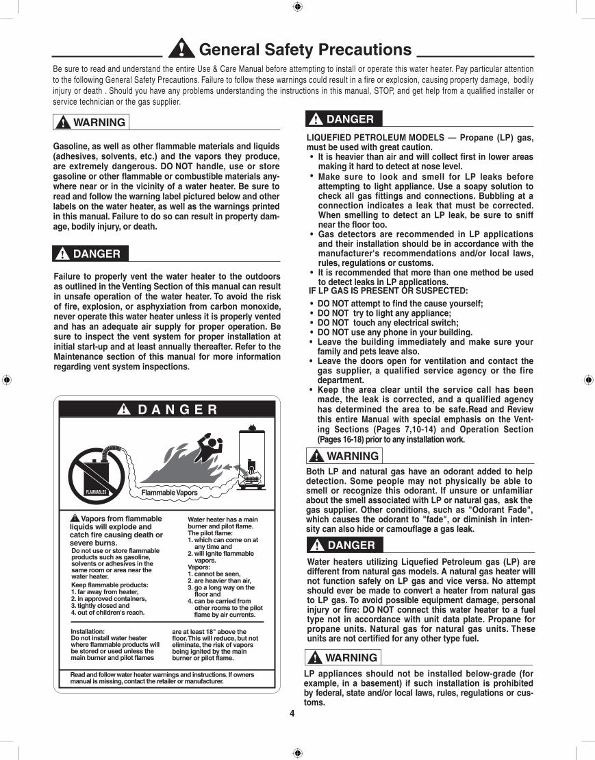
general Safety PrecautionsBe sure to read and understand the entire Use & Care Manual before attempting to install or operate this water heater. Pay particular attention to the following General Safety Precautions. Failure to follow these warnings could result in a fire or explosion, causing property damage, bodily injury or death . Should you have any problems understanding the instructions in this manual, STOP, and get help from a qualified installer or service technician or the gas supplier.
DANGER!
DANGER!
WARNING!
Failure to properly vent the water heater to the outdoors as outlined in the Venting Section of this manual can result in unsafe operation of the water heater. To avoid the risk of fire, explosion, or asphyxiation from carbon monoxide, never operate this water heater unless it is properly vented and has an adequate air supply for proper operation. Be sure to inspect the vent system for proper installation at initial start-up and at least annually thereafter. Refer to the maintenance section of this manual for more information regarding vent system inspections.
DANGER!
WARNING!
liQUEFiED PETROlEUm mODElS — Propane (lP) gas, must be used with great caution.• it is heavier than air and will collect first in lower areas
making it hard to detect at nose level.• make sure to look and smell for lP leaks before
attempting to light appliance. Use a soapy solution to check all gas fittings and connections. Bubbling at a connection indicates a leak that must be corrected. When smelling to detect an lP leak, be sure to sniff near the floor too.
• gas detectors are recommended in lP applications and their installation should be in accordance with the manufacturer's recommendations and/or local laws, rules, regulations or customs.
• it is recommended that more than one method be used to detect leaks in lP applications.
iF lP gAS iS PRESENT OR SUSPECTED:• DO NOT attempt to find the cause yourself;• DO NOT try to light any appliance;• DO NOT touch any electrical switch;• DO NOT use any phone in your building.• leave the building immediately and make sure your
family and pets leave also.• leave the doors open for ventilation and contact the
gas supplier, a qualified service agency or the fire department.
• Keep the area clear until the service call has been made, the leak is corrected, and a qualified agency has determined the area to be safe.Read and Review this entire manual with special emphasis on the Vent-ing Sections (Pages 7,10-14) and Operation Section (Pages 16-18) prior to any installation work.
gasoline, as well as other flammable materials and liquids (adhesives, solvents, etc.) and the vapors they produce, are extremely dangerous. DO NOT handle, use or store gasoline or other flammable or combustible materials any-where near or in the vicinity of a water heater. Be sure to read and follow the warning label pictured below and other labels on the water heater, as well as the warnings printed in this manual. Failure to do so can result in property dam-age, bodily injury, or death.
Both lP and natural gas have an odorant added to help detection. Some people may not physically be able to smell or recognize this odorant. if unsure or unfamiliar about the smell associated with lP or natural gas, ask the gas supplier. Other conditions, such as "Odorant Fade", which causes the odorant to "fade", or diminish in inten-sity can also hide or camouflage a gas leak.
!
Water heaters utilizing liquefied Petroleum gas (lP) are different from natural gas models. A natural gas heater will not function safely on lP gas and vice versa. No attempt should ever be made to convert a heater from natural gas to lP gas. To avoid possible equipment damage, personal injury or fire: DO NOT connect this water heater to a fuel type not in accordance with unit data plate. Propane for propane units. Natural gas for natural gas units. These units are not certified for any other type fuel.
lP appliances should not be installed below-grade (for example, in a basement) if such installation is prohibited by federal, state and/or local laws, rules, regulations or cus-toms.
WARNING!
!
D A N G E R!
FLAMMABLES Flammable Vapors
Vapors from flammableliquids will explode andcatch fire causing death orsevere burns.Do not use or store flammableproducts such as gasoline,solvents or adhesives in thesame room or area near thewater heater.Keep flammable products:1. far away from heater,2. in approved containers,3. tightly closed and4. out of children's reach.
Water heater has a mainburner and pilot flame.The pilot flame:1. which can come on at
any time and2. will ignite flammable
vapors.Vapors:1. cannot be seen,2. are heavier than air,3. go a long way on the
floor and4. can be carried from
other rooms to the pilot flame by air currents.
Installation:Do not install water heaterwhere flammable products willbe stored or used unless themain burner and pilot flames
are at least 18" above thefloor. This will reduce, but noteliminate, the risk of vaporsbeing ignited by the mainburner or pilot flame.
Read and follow water heater warnings and instructions. If ownersmanual is missing, contact the retailer or manufacturer.

5
LOCAL INSTALLATION REGULATIONSThis water heater must be installed in accordance with these instructions, local codes, utility company requirements and/or, in the absence of local codes, the latest edition of the National Fuel Gas Code, ANSI Z223.1 in the United States, or CAN/CSA B149.1 Installation Codes in Canada.
LOCATIONA. If this water heater is of the Direct Vent design, all air for combustion
and all products of combustion are routed through the venting system, directly from and to the outside of the building.
Otherwise: This unit can also be set up as a Power Vent Unit. Combus-tion air for a power vent unit will be obtained from the surrounding area. Make sure that there is an adequate air supply for the water heater, see codes in "Local Installation Regulations".
The water heater should be installed in a clean, dry location as close as practical to the vent terminals. Long hot water lines should be insulated to conserve water and energy. The water heater and water lines should be protected from exposure to freezing temperatures.
B. A gas fired water heater should not be installed in a space where liquids which give off flammable vapors are to be used or stored. Such liquids include gasoline, LP gas (butane and propane), paint or adhesives and their thinners, solvents or removers. Because of natural air movement in a room or other enclosed space, flammable vapors can be carried some distance from where their liquids are being used or stored. The open flame of the water heater’s main burner can ignite these vapors causing an explosion or fire which may result in severe burns or death to those in range, as well as property damage. For these reasons, installation of a gas fired water heater in a garage is not desirable.
C. All models are certified for installation on combustible floors and in alcoves. The minimum side and top clearance to walls and ceiling for providing protection of combustible materials are shown on the water heater’s rating label. A front clearance of 18 inches (46 cm) should be provided for adequate inspection and servicing.
If the water heater must be installed on carpeting, place a metal or wood panel beneath water heater extending beyond its full width and depth at least 3 inches (7.6 cm) in all directions. If the water heater is installed in an alcove, the entire floor must be covered by the panel.
NOTICE: Auxiliary catch pan installation MUST conform to the ap-plicable local codes.
The water heater should not be located in an area where leak-age of the tank or connections will result in damage to the area adjacent to it or to lower floors of the structure. When such areas cannot be avoided, it is recommended that a suitable catch pan, adequately drained, be installed under the water heater. The pan mUST NOT interfere with the operation of the water heater and access of the serviceable components.
D. RESTAURANT INSTALLATION: — If the water heater is to be installed in a restaurant or other location where NSF International listing is re-quired, this unit must be sealed to the floor and other components must be added utilizing Rheem's UL Listed NSF Seal Kit. A factory designed sealing kit is available from the distributor or store where the water heater was purchased. When installed according to the instructions supplied with the kit, these heaters will meet the NSF international requirements.
E. CORROSIVE ATMOSPHERES — The heater should not be installed near an air supply containing halogenated hydrocarbons. For example, the air in beauty shops, dry cleaning establishments, photo process-ing labs, and storage areas for liquid and powdered bleaches or swim pool chemicals often contain such hydrocarbons. The air there may be safe to breathe, but when it passes through a gas flame, corrosive elements are released that will shorten the life of any gas burning appliance. Propellants from common spray cans or gas leaks from refrigeration equipment are highly corrosive after passing through a flame. The limited warranty is voided when failure of water heater is due to a corrosive atmosphere. (Refer to the Certificate of Limited Warranty for complete terms and conditions.)The manufacturer’s warranty does not cover any damage or defect caused by installation, or attachment, or use of any special attachment such as energy saving devices (other than those authorized by the manufacturer) into, onto, or in conjunc-tion with the water heater. The use of such unauthorized devices may shorten the life of the water heater and may endanger life and property. The manufacturer disclaims any responsibility for such loss or injury resulting from the use of such unauthorized devices.
1. INSPECT SHIPMENT — for possible damage. The manufacturer’s re-sponsibility ceases upon delivery of goods to the carrier in good condi-tion. Any claims for damage, shortage in shipments, or non delivery must be filed immediately against carrier by consignee.
2. THERMAL EXPANSION — Determine if a check valve exists in the inlet water line. It may have been installed in the cold water line as a separate back flow preventer, or it may be part of a pressure reducing valve, water meter or water softener. A check valve located in the cold water inlet line can cause what is referred to as a ”closed water sys-tem”. A cold water inlet line with no check valve or back flow prevention device is referred to as an ”open” water system.
As water is heated, it expands in volume and creates an increase in the pressure within the water system. This action is referred to as ”thermal expansion”. In an ”open” water system, expanding water which exceeds the capacity of the water heater flows back into the city main where the pressure is easily dissipated.
A ”closed water system”, however, prevents the expanding water from flowing back into the main supply line, and the result of ”thermal expansion” can create a rapid, and dangerous pressure increase in the water heater and system piping. This rapid pressure increase can quickly reach the safety setting of the relief valve, causing it to oper-ate during each heating cycle. Thermal expansion, and the resulting rapid, and repeated expansion and contraction of components in the water heater and piping system can cause premature failure of the relief valve, and possibly the heater itself. Replacing the relief valve will not correct the problem!
The suggested method of controlling thermal expansion is to install an expansion tank in the cold water line between the water heater and the check valve. The expansion tank is designed with an air cushion built in that compresses as the system pressure increases, thereby relieving the over pressure condition and eliminating the repeated operation of the relief valve. Other methods of controlling thermal expansion are also available. Contact your installing contractor, water supplier, or plumbing inspector for additional information regarding this subject.
If a recirculation line is installed, the return connection should be made to a tee close to the inlet connection on the water heater. A check valve should always be installed in the recirculation line to prevent cold water from entering.
introduction
CAUTION!

WATER CONNECTIONS — This water heater may be connected indi-vidually, in multiples with others, or with an external hot water storage tank.
Inlet water connections are made to the lower coupling on the heater, and outlet water connections are made to the upper coupling.
Each water heater is supplied with the necessary components (Dif-fuser tubes) to make the water connections that will ensure proper performance. The components are supplied in a bag attached to the water heater. If special instructions are required for any specific water heater, they will be included in the bag.
Cap or plug unused connections. Use only clean, new galvanized steel, copper or approved plastic pipe for water connections. Local codes or regulations shall govern the exact type of material to be used. The installation of unions on the inlet and outlet water lines and a shut-off valve in at least the cold water inlet line is recommended, so the water heater may be easily disconnected for servicing. Dielectric unions are not required for protection of water heater.
When this water heater is supplying general purpose hot water require-ments for use by individuals, a thermostatically controlled mixing valve is recommended to reduce the risk of scald injury. Contact a licensed plumber or the local plumbing authority for further information.
Thermometer(s) should be installed so that they indicate the tempera-ture of the water at or near the outlet of the water heater and storage tank(s) if provided. See Fig. 2.
3. RELIEF VALVE — A new factory installed combination pressure and temperature relief valve, complying with the Standard for Relief Valves and Automatic Gas Shutoff Devices for Hot Water Supply Systems, ANSI Z21.22, or Standard CSA 4.4, Temperature, Pressure, Tempera-ture and Pressure Relief Valves and Vacuum Relief Valves is provided with the water heater. No valve is to be placed between the relief valve and the water heater. For a circulating tank installation, the separate storage tank(s) must have similar protection. The pressure rating of the relief valve must not exceed 150 psi (1034 kPa) (160 psi for ASME models), the maximum working pressure as marked on front of the water heater.
Connect the outlet of the relief valve to a suitable open drain. The discharge line must pitch downward from the valve to allow complete draining (by gravity) of the relief valve and discharge line, and be no smaller than the outlet of the valve. The end of the discharge line should not be threaded or concealed and should be protected from freezing. No valve of any type, restriction or reduc-er coupling should be installed in the discharge line. local codes shall govern the installation of relief valves.
The Btu/h rating of the relief valve must equal or exceed the Btu/h input of the water heater as marked on its rating plate.
4. GAS SUPPLY — The inlet gas pressure to the water heater must not exceed 10.5” w.c. (2.6 kPa) for Natural gas and 13.0" w.c. (3.2 kPa) for L.P. gas. The minimum inlet gas pressure (with main burner on) is shown on the rating plate. Check to see if high or low gas pressure is present and then contact the gas company for correction.
The gas line should be of adequate size to prevent undue pressure drop. Sizing based upon information in Table 2. No additional allowance is necessary for an ordinary number of fittings.
A ground joint union and manual shutoff valve should be installed in the gas line near the water heater so that the burner assembly may be easily removed. The shut-off valve must be readily accessible for turning on or off. See Fig. 2.
Where a sediment trap is not incorporated as part of the appliance, a sediment trap shall be installed downstream of the equipment shutoff valve as close to the inlet of the appliance as practical at the time of the appliance installation. The sediment trap shall be either a tee fitting with a capped nipple in the bottom outlet or other device recognized as an effective sediment trap. See Fig. 2.
LEAK TESTING — The water heater and its gas connections MUST be leak tested at normal operating pressure before it is placed in op-eration. Turn ON the manual gas shut-off valve near the water heater. Use a soapy water solution to test for gas leaks at all connections and fittings. Bubbles indicate a gas leak that must be corrected. The water heater factory connections to the gas valve should also be leak tested after placing the water heater in operation.
NEVER use open flame to test for gas leaks, as bodily injury or prop-erty damage could result.
PRESSURE TESTING THE GAS SUPPLY SYSTEM — The water heater and its manual gas shut-off valve MUST be disconnect-ed from the gas supply piping system during any high pressure testing of that system at pressures in excess of 1/2 psi (14” w.c. / 3.5 kPa).
The water heater MUST be isolated from the gas piping system by closing the manual gas shut-off valve during any pressure test-ing of the gas supply piping at pressures equal to or less than 1/2 psi (14” w.c. / 3.5 kPa).
5. CONDENSATEFilling The Condensate Trap:
THE CONDENSATE TRAP MUST BE FILLED WITH WATER, BEFORE OPERATING WATER HEATER.
To fill the trap (Refer to Figure 1), remove the plastic cap on the left side of the trap. Pour about one (1) cup of water into the trap and then re-install the plastic cap.
This is a condensing high efficiency appliance, therefore this unit has a condensate removal system. Condensate is nothing more than water vapor, derived from the combustion products. This condensate does have a low pH and condensate removal must comply with all local codes. See information below for optional Condensate Neutralizer, if required. It is very important that the condensate line is sloped away from and down to a suitable inside drain. If the condensate outlet on this unit is lower than the drain, you must use a condensate removal pump. It is also very important that the condensate line is not exposed to freezing temperatures, or any other type of blockage. Plastic tubing should be the only material used for the condensate line. Steel, brass, copper, or other metals will be subject to corrosion and deterioration. A second vent may be necessary to prevent condensate line vacuum lock if a long horizontal run is used. Also an increase to 1" tubing may be necessary.
6
installation
WARNING!

7
installation
Plastic Cap
Figure 1 - Condensate Trap
CONDENSATE LINE CONDENSATE LINE WITH PUMP
TO DRAIN
TO DRAIN
iNSTAllATiON OF A CONDENSATE NEUTRAliZER AND PUmP (Not Supplied)
Condensate line must be pitched down at least 1/4" per foot to prop-erly drain. If this cannot be done or a very long length of condensate hose is used, you must increase the condensate hose to a minimum
of 1" ID and place a tee in the line after the condensate neutralizer, to properly reduce vacuum lock in the drain line.
6. WIRING — A polarized 120V 50/60 Hz power supply, with suitable disconnect means, must be connected to the black and white leads provided. The maximum current draw by these models is 6 Amps. The water heater, when installed, must be electrically grounded in ac-cordance with local codes, or, in the absence of local codes, with the National Electrical Code, ANSI/NFPA 70 in the United States; or CSA C22.1 Electrical Code, in Canada. Improper grounding may result in abnormal operation of the unit . Refer on page 31 of this manual for water heater internal wiring diagrams.
The water heater must be vented to the outdoors as described in these instructions.
DO NOT connect this water heater to an existing Vent or Chim-ney; it must be vented separately from all other appliances.
Failure to properly vent the water heater to the outdoors as out-lined above and in the following section can result in unsafe opera-tion of the water heater causing bodily injury, explosion, fire or death.
NOTICE: DO NOT use in conjunction with a GFCI.To avoid the risk of fire, explosion or asphyxiation from carbon monoxide, NEVER operate this water heater unless it is properly vented and has an adequate air supply for proper operation. The vent pipe must overlap a minimum of ½" on each connection. it is important that the vent pipe engages fully into any pipe fitting and be kept in that position until the adhesive has fully cured. DO NOT drill or punch holes in the plastic pipe or fittings.
WARNING!
WARNING!
WARNING!
WARNING!

8
installation
Temperature & PressureRelief Valve
Air Gap 6"
Hot Outlet
Cold WaterInlet
Thermal Expansion Tank (if required)
Shut -Off Valve
Vacuum Relief Valve (Not Supplied)
If required, install per local codes and valve manufacturer’s
instructions.
Figure 2. — Typical installation Drawing.
Vacuum Relief Valve (Not Supplied)
If required, install per local codes and valve manufacturer’s
instructions.
* Can be GHE or THE
Gas Valve Pipe Size*130,160 & 200 1/2" NPT*250, 300 ,350 3/4" NPT
Sediment Trap
To Gas Supply
Manual Gas Shut Off
Gas Pipe to Gas Valve
Discharge Line to suitable open drain
NOTES:1.) The gas supply piping must be adequately supported and
aligned to minimize loads (forces) on the water heater’s gas valve and burner system.
2.) Refer to local codes for installation guidelines for the Ther-mal Expansion Tank (if required).
Condensate Trap

9
7. VENTING —NOTE: This unit can be vented either as a Direct Vent or Power Vent configuration. NOTICE: This unit can be vented using only the following
recommended pipe material . Use only 2, 3- or 4-inch diameter pipe .Refer to local codes for restrictions on the use of PVC, CPVC or ABSpipe and fittings . All exhaust venting materials for product installed in Canada must meet ULC-S636 . PVC (Schedule 40, ASTM D-1785)
CPVC (Schedule 40, ASTM F-441) ABS (Schedule 40, ASTM D-2661)(Not permitted in Canada)
PVC Cellular Core (Schedule 40, ASTM F-891)(Not Permitted in Canada)
The fittings, other than the VENT TERMINAL, should be equiv-alent to the following:
PVC (Schedule 40 DWV, ASTM D-2665) CPVC (Schedule 40 DWV, ASTM F-438) ABS (Schedule 40 DWV, ASTM D-2661)(Not permitted in Canada)
The unit may be vented horizontally through a wall or vertically through the roof. Pipe runs must be adequately supported along both vertical and horizontal runs. Maximum unsupported span is recommended to be no more than 4 feet. It is imperative that the first hanger be located on the horizontal run immediately adjacent to the first 90-degree elbow from the vertical rise or at the blower outlet in the case of a horizontal blower position. Support method used should isolate the vent pipe from floor joists or other structural members to help prevent the transmis-sion of noise and vibration. Do not support, pin or otherwise secure the venting system in a way that restricts the normal thermal expansion and contraction of the chosen venting material.
If the water heater is being installed as a replacement for an existing power vented water heater, a thorough inspection of the existing venting system must be performed prior to any installation work. Verify that the correct materials, as detailed above have been used, and that the minimum or maximum vent length and terminal locations as detailed in this manual have been met. Carefully inspect the entire venting system for any signs of cracks or fractures, particularly at the joints between elbows or other fittings and the straight runs of vent pipe. Check the system for signs of sagging or other stresses in the joints as a result of misalignment of any components in the system. If any of these conditions are found, they must be corrected in accordance with the venting instructions in this manual before completing the installation and putting the water heater into service.
VENT PIPE CONNECTION —NOTE: This unit can be vented either as a Direct Vent or Power Vent configuration.
Refer to Figure 3, for connecting the vent pipe to the water heater. These models can be vented either as a Direct Vent or as a Power Vent water heater.
NOTICE: If the unit is installed as a Power Vent water heater, the vent terminal with screen must still be installed on the inlet air side.
Before starting the vent installation, careful planning should be given to the routing and termination of the vent pipes. The length of the vent pipes (inlet and outlet) should be kept to a minimum. Also, see Figure 10 for vent terminal placement. Refer to the venting charts on Table 1, for the pipe sizes that can be used and the total equivalent length of pipe that can be used. Do not exceed equivalent length of pipe in charts.
Depending on the size of pipe that is chosen for venting the water heater, it might be necessary to use a fitting for stepping up or down in pipe size, to connect to the water heater. All models are shipped with three ( 3 ) inch vent terminals with screen. If another size of pipe is used for venting the unit, the proper vent terminal must be installed.
When the unit is vented as a Direct Vent , though a side wall, the vent terminals must be on the same exterior wall mounted horizontally and at least twenty-four (24) inches apart (on center). See Figure 10 for other vent terminal restrictions.
JOINING PIPES AND FITTINGS – All pipe, fittings, solvent cement, primers and procedures, for the U.S., must conform to American National Standards Institute and American Society for Testing and Materials (ANSI/ASTM) standards. For Canada, all pipe, fittings, solvent cement, primers and procedures must conform to ULC-S636 and vent manufacture specifications
. CEMENTING JOINTS – All joints in the vent piping must be properly
sealed and we recommend using the following material: PVC materials should use ASTM D-2564 grade cement. CPVC materials should use ASTM F-493 grade cement. ABS materials should use ASTM D-2235 grade cement. (ABS is not allowed in Canada)
Cleaner-Primer and Medium Body Solvent Cement1. Cut pipe end square, remove jagged edges and burrs. Chamfer end of
pipe, then clean fitting socket and pipe joint area of all dirt, grease or moisture.
2. After checking pipe and socket for proper fit, wipe socket and pipe with cleaner-primer. Apply a liberal coat of primer to inside surface of socket and outside of pipe. Do not allow primer to dry before applying cement.
3. Apply a thin coat of cement evenly in the socket. Quickly apply a heavy coat of cement to the pipe end and insert pipe into fitting with a slight twisting motion until it bottoms out.
NOTICE: Cement must be fluid; if not, re-coat.4. Hold the pipe fitting for 30 seconds to prevent the tapered socket from
pushing the pipe out of the fitting.
5. Wipe all excess cement from the joint with a rag. Allow 15 minutes before handling. Cure time will vary according to fit, temperature and humidity.
installation
Figure 3. — Vent Pipe Connection locations

10
NOTICE: Stir the solvent cement frequently while using. Use a natural bristle brush or the dauber supplied with the can. The proper brush size is one inch.
FOR PROPER iNSTAllATiON:
CAUTION!• DO NOT use solvent cement that has become
curdled, lumpy or thickened.
• DO NOT thin solvent cement. Observe shelf precautions printed on the containers.
• For applications below 32°F use only low temperature type solvent cement.
• Appropriate solvent and cleaner must be used for the type of vent pipe used (PVC, CPVC or ABS).
WARNING!
DANgER OF FiRE OR BODilY iNJURY – Solvent cements and primers are highly flammable. Pro-vide adequate ventilation and do not assemble near heat source or open flame. Do not smoke. Avoid skin or eye contact. Observe all cautions and warnings on material containers.
DiRECT VENT iNSTAllATiON - Check to make sure flue gases do not recirculate into the air intake terminal when using direct venting. If the water heater is having service issues, flue recirculation may be a contributing factor. Even when the minimum vent terminal separation distances are followed, recirculation may still occur depending upon the location outside the building, the distance from other buildings, prox-imity to corners, weather conditions, wind patterns, and snow depth. Periodically check to make sure that flue recirculation is not occurring. Signs of flue gas recirculation include frosted or frozen intake termi-nals, condensate in the intake terminal and venting system, oxidation or white chalk material on the flame sensor or igniter shield. Correction to flue recirculation may involve angling the intake away from the ex-haust terminal, increasing the distance between them, or using inside
air for combustion. Check to be sure the intake and exhaust terminals are not obstructed, especially during periods of below freezing weather.
All intake and exhaust venting components must have the same diam-eter size. Do not use a different size on the intake and exhaust venting.
Be sure the condensate runs freely to a drain and does not accumulate inside the water heater. In cold climates, precautions may need to be taken to insure that the condensate drain does not freeze. Make sure the condensate trap or drain loop is installed to prevent flue gases from being discharged into the room. Refer to the Venting section of the Installation and Operating Instructions Manual for complete instructions on venting and condensate drainage.
Stress levels in the pipe and fittings can be significantly increased by improper installation. If rigid pipe clamps are used to hold the pipe in place, or if the pipe cannot move freely through a wall penetration, the pipe may be directly stressed, or high thermal stresses may be formed when the pipe heats up and expands. Install accordingly to minimize such stresses. Follow the following procedure to vent through the wall:
1. Cut two 2 1/2" (6.4 cm) diameter holes (for a 2" (5.1 cm) diameter pipe), 3 1/2 in. (8.9 cm) diameter holes (for 3” (7.6 cm) diameter pipe) or 4 ½” (11.4 cm) diameter holes (for 4” (10.2 cm) diameter pipe) in the wall. Vent terminals must be a minimum of 24 inches (61 cm) and a maximum of 36 inches ( cm) horizontally apart (See Figure 4).
2. Use the proper PVC cement to secure the exhaust vent and air intake terminals provided with the water heater to the plastic pipes. The distance between the back edge of the exhaust vent terminal and the exterior wall (see Figure 7) must be 6 inches (12.7 cm) more for the exhaust vent terminal than the air intake terminal. Use the proper cement or sealant and assembly procedures to secure the vent connector joints between the terminal and the blower outlet. Provide support brackets for every 3 feet (.91 m) of horizontal vent beyond the intake terminal as seen in Figure 7.
installation

11
Power Direct Vent
Vent Pipe Size ( In. )
2 3 4
Model Maximum Vent Length for Inlet or Outlet ( ft. )
*GHE100-130 20 60 85
GHE100-160 20 50 75
GHE100-200 20 40 65
GHE100-250 n/a 40 65
GHE100-300 n/a 40 40
GHE100-350 n/a 40 40
For each 90° elbow, reduce pipe length by five ( 5 ) feet. For each 45° elbow, reduce pipe length by five ( 2.5 ) feet.
Example of Venting for 2” Power Direct Vent Setup :Refer to the chart above, “ Power Direct Vent”, for actual vent length allowed on each model.
Number of 90° Elbows excluding Vent Terminals
Number of 45° Elbows
Minimum Pipe
Length Required
(ft)
Maxi-mumPipe
Length(ft)
Inlet Vent Outlet Vent
None None None 5.0 20.0
One ( 1 ) One ( 1 ) None ----- 15.0
One ( 1 ) One ( 1 ) One ( 1 ) ----- 12.5
Two ( 2 ) Two ( 2 ) None ----- 10.0
Two ( 2 ) Two ( 2 ) One ( 1 ) ----- 7.5
Three ( 3 ) Three ( 3 ) None ----- 5.0
Three ( 3 ) Three ( 3 ) One ( 1 ) ----- 2.5
miNimUm AND mAximUm VENT lENgThSNote: Vent pipe size should not be mixed for venting these units. Use same size pipe fo all venting of the unit.
NOTICE: Vent terminals need to be mounted horizontally a minimum of 24 inches (center to center) horizontally apart and a maximum of 36 inches apart (center to center) See Figure 12 for venting multiple units.
Power Vent
Vent Pipe Size ( In. )
2 3 4
Model Maximum Vent Length for Outlet ( ft. )
GHE100-130 20 60 85
GHE100-160 20 50 75
GHE100-200 20 40 65
GHE100-250 n/a 40 65
GHE100-300 n/a 40 40
GHE100-350 n/a 40 40
For each 90° elbow, reduce pipe length by five ( 5 ) feet. For each 45° elbow, reduce pipe length by five ( 2.5 ) feet.
Example of Venting for a 4” Power Vent Setup (GHE100-130) Refer to the chart above, “ Power Vent”, for actual vent length allowed on each model.
Number of 90° Elbows, excluding Vent Terminals
Number of 45 ° Elbows
Minimum Pipe
Length Required
(ft)
Maxi-mum Pipe
Length(ft)
Outlet Vent
None None 5.0 85.0
One ( 1 ) None ----- 80.0
One ( 1 ) One ( 1 ) ----- 77.5
Two ( 2 ) None ----- 75.0
Two ( 2 ) One ( 1 ) ----- 72.5
Three ( 3 ) None ----- 70.0
Three ( 3 ) One ( 1 ) ----- 67.5
Four ( 4 ) None ----- 65.0
Four ( 4 ) One ( 1 ) ----- 62.5
Five ( 5 ) None ----- 60.0
*NOTICE: The GHE Prefix on the model numbers above can also be THE.
TABLE 1.DO NOT exceed the venting distances or the number of elbows listed in this manual.
Exceeding the maximum lengths may cause the water heater to malfunction or cause a lock-out condition.
installation

12
HORIZONTAL VENT INSTALLATION – Once the vent terminal location has been determined, make a hole through the exterior wall to accommodate the vent pipe. Vent pipe must exit exterior wall horizontally only (See Figure 5).
Insert a small length of vent pipe through the wall and connect the coupling as shown in Figure 5. Connect terminal as shown to the vent pipe on the exterior of the building. Seal any opening around the vent pipe or fittings with mortar or silicone caulk as shown in Figure 5.
Complete the rest of the vent pipe installation to the water heater’s vent connector f i tt ing on the blower outlet. If necessary support horizontal run as previously mentioned.
Figure 6 – Vertical Vent Terminal location
Short Piece of Vent Pipe
*Min. 12" Above Roof
or
Min. 12" Above Anticipated Snow Level.
Max. 24" Above Roof (Without Additional Support)
Vent PipeThrough Roof
Elbows
Figure 4
Min. 24"Max. 36"
Inlet Outlet
Additional Considerations (See Figure 9 & 10)1. Do Not install vent terminals under any patio or deck.2. To help prevent moisture from freezing on walls and under eaves, do
not locate outlet vent terminal on the side of a build ing with prevailing winter winds.
3. Do Not terminate vent pipe directly on brick or masonry surfaces. Use a rust-resistant sheet metal backing plate behind vent. (See Figure 5.)
4. Do Not locate vent terminal too close to shrubbery, since flue gases may damage them.
5. Caulk all cracks, seams and joints within six (6) (1.83 m) feet of vent terminal.
6. All painted surfaces should be primed to lessen the chance of physical damage. Painted surfaces will require maintenance.
7. Insulate vent pipe exposed to cold conditions (attics, crawl spaces, etc.) to help prevent moisture from accumulating in vent pipe.
8. This water heater requires its own separate venting system. DO NOT connect the exhaust vent to an existing vent pipe or chimney.
WARNING!moisture in the flue gas will condense as it leaves the vent terminal. in cold weather this condensate can freeze on the exterior wall, under the eaves and on surrounding objects. Some discoloration to the exterior of the building is to be expected. however, improper location or installation can result in se-vere damage to the structure or exterior finish of the building.
VERTICAL VENT INSTALLATION – Once the vent termi-nal location has been determined, make a hole through the roof and interior ceiling to accommodate the vent pipe. Com-plete the vent pipe installation to the water heater’s vent connector fitting on the blower outlet. Suppor t ver tical or horizontal runs as previously mentioned.
Install adequate flashing where the vent pipe passes through the roof. Determine the vent terminal height and cut vent pipe accord-ingly. Refer to Fig. 8 for proper vent terminal height. Connect vent elbow onto vertical pipe through roof. Connect short piece of vent pipe (approximately 3" (7.6 cm) long) to elbow, then join terminal to the short piece of vent pipe.
VERTICAL VENT TERMINAL LOCATION – The location of vertical vent terminal depends on the following considerations (see Figure 6):1. Minimum twelve (12 inches) (30.5 cm) above roof 18" inches (46
cm) for Canada.2. Minimum twelve (12 inches) (30.5 cm) inches above anticipated snow
level.3. Maximum twenty-four (24 inches) (61 cm) inches above roof level without
additional support for vent pipe.4. Four (4) feet (1.22 m) from any gable, dormer or other roof structure
with building interior access (i.e., vent, window, etc.).5. Ten (10) feet (3.05 m) from any forced air inlet to the building.
Any fresh or make-up air inlet such as a dryer or furnace area is considered to be a forced air inlet.
6. Vent Terminals are a minimum of twenty-four (24) inches (61 cm) and a max of 36" horizontally apart.
VENT INSTALLATION – Before proceeding, make cer tain you understand the procedure and cautions covered in the section “Joining Pipes and Fittings.”
installation
Figure 5 – Typical horizontal Vent installation
Pipe & Coupling
Sheet Metal Shield on Brick or Masonry Walls
Outside ofBuilding Wall
From Water Heater
Vent Pipe
Vent Terminal with 1/2" Mesh ProtectiveScreen Inside
Vent Pipe
* Min of 18" for Canada

installation
13
Figure - 7- Typical Horizontal Direct Vent System
SUPPORT BRACKET
EVERY 3' MAX.
2, 3, OR 4" PVC PIPE
45° TERMINAL
1"
WALL
DRAIN PAN
WATER HEATER
FLOOR

installation
Through The Wall Venting With Low Ground Clearance: When venting cannot exit through the wall at a height greater than or equal to 12” (30.5 cm) (and above expected snow level) from the ground, then the
installation must be modified as shown below (see Figure 9).
Figure 9. Vent Terminal (Low Ground Clearance)
STRAIGHT EXHAUST TERMINAL
90° INTAKE TERMINAL
SUPPORT BRACKET
WATER HEATER
FLOOR
Figure 8. Typical Vertical Direct Vent System Installation
NOTICE: Intake and exhaust terminals must be on the same outside wall.
3" (97.6 CM) OR 4" (10.2 CM) PVC
3" 97.6 CM) OR 4" (10.2 CM) PVC90° INTAKE
TERMINAL
90° INTAKE TERMINAL
12" (30.5 CM) MIN.
12" (30.5 CM) MIN.
GROUND LEVEL
GROUND LEVEL
1" (2.54 CM) 6" (15.2 CM)
14
24" Min.
24" Above anticipated. snow level.

15
D
V
V
E
FIXED
CLOSED
OPERAB
LE
OPERAB
LEFIXE
D
CLOSED
v
v
B
L
F
C
B
v
v
v
X
B
B
BA
J
C
I
H
X v
M
K
v
G
A
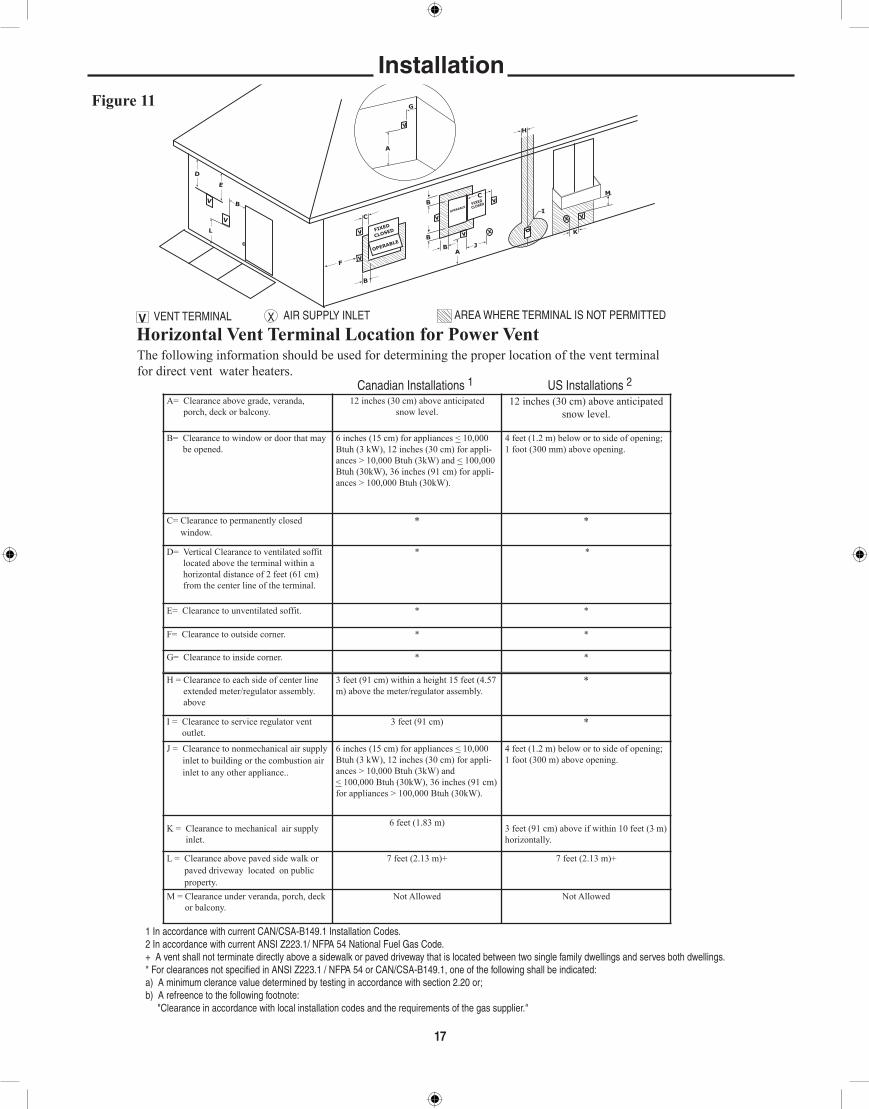
The following information should be used for determining the proper location of the vent terminal for direct vent water heaters.
V VENT TERMINAL X AIR SUPPLY INLET AREA WHERE TERMINAL IS NOT PERMITTED
HorizontalVentTerminalLocationforPowerDirectVent
Canadian Installations 1 US Installations 2A= Clearance above grade, veranda,
porch, deck or balcony. 12 inches (30 cm) above anticipated
snow level.12 inches (30 cm) above anticipated
snow level.
B= Clearance to window or door that may be opened.
6 inches (15 cm) for appliances < 10,000 Btuh (3 kW), 12 inches (30 cm) for appli-ances > 10,000 Btuh (3kW) and < 100,000 Btuh (30kW), 36 inches (91 cm) for appli-ances > 100,000 Btuh (30kW).
6 inches (15 cm) for appliances.< 10,000 Btuh (3 kW), 9 inches (23 cm) for appli-ances > 10,000 Buth (3 kW) and < 50,000 Btuh (15 kW), 12 inches (30 cm) for appli-ances > 50,000 Btuh (15 kW)
C= Clearance to permanently closed window.
* *
D= Vertical Clearance to ventilated soffit located above the terminal within a horizontal distance of 2 feet (61 cm) from the center line of the terminal.
* *
E= Clearance to unventilated soffit. * *
F= Clearance to outside corner. * *
G= Clearance to inside corner. * *
Figure 10
1 In accordance with current CAN/CSA-B149.1 Installation Codes.2 In accordance with current ANSI Z223.1/ NFPA 54 National Fuel Gas Code.+ A vent shall not terminate directly above a sidewalk or paved driveway that is located between two single family dwellings and serves both dwellings.* For clearances not specified in ANSI Z223.1 / NFPA 54 or CAN/CSA-B149.1, one of the following shall be indicated:a) A minimum clerance value determined by testing in accordance with section 2.20 or;b) A refreence to the following footnote: "Clearance in accordance with local installation codes and the requirements of the gas supplier."
H = Clearance to each side of center line extended meter/regulator assembly. above
3 feet (91 cm) within a height 15 feet (4.57 m) above the meter/regulator assembly.
*
I = Clearance to service regulator vent outlet.
3 feet (91 cm) *
J = Clearance to nonmechanical air supply inlet to the building or the combustion air inlet of any other appliance..
6 inches (15 cm) for appliances < 10,000 Btuh (3 kW), 12 inches (30 cm) for appli-ances > 10,000 Btuh (3kW) and < 100,000 Btuh (30kW), 36 inches (91 cm) for appliances > 100,000 Btuh (30kW).
6 inches (15 cm) for appliances.< 10,000 Btuh (3 kW), 9 inches (23 cm) for appli-ances > 10,000 Buth (3 kW) and < 50,000 Btuh (15 kW), 12 inches (30 cm) for appli-ances > 50,000 Btuh (15 kW)
K = Clearance to mechanical air supply inlet.
6 feet (1.83 m) 3 feet (91 cm) above if within 10 feet(3 m) horizontally.
L = Clearance above paved side walk or paved driveway located on public property.
7 feet (2.13 m)+ 7 feet (2.13 m)+
M = Clearance under veranda, porch, deck or balcony.
Not Allowed Not Allowed
installation

16
POWER VENT INSTALLATION: Power venting is where the indoor air is used and the exhaust is vented
to the outside. Venting may be run horizontally through an outside wall or vertically through a roof through using either 2" (5.1 cm), 3" (7.6 cm) or 4" (10.2 cm) diameter PVC, ABS or CPVC. This water heater is supplied with a screened intake elbow and exhaust coupling referred to as the air intake terminal and the exhaust vent terminal
In a horizontal application, it is important that condensate not be allowed to buildup in the exhaust vent pipe. To prevent this from hap-
pening, the pipe should be installed with a slight upward slope of ¼” per foot. The vent system must be supported every 5 feet of vertical run and every 3 feet of horizontal run of vent pipe length.
Failure to properly support the vent piping with hangers and clamps may result in damage to the water heater or venting system.
CAUTION!
installation
D
V
V
E
FIXED
CLOSED
OPERAB
LE
OPERAB
LEFIXE
D
CLOSED
v
v
B
L
F
C
B
v
v
v
X
B
B
BA
J
C
I
H
X v
M
K
v
G
A
The following information should be used for determining the proper location of the vent terminal for direct vent water heaters.
V VENT TERMINAL X AIR SUPPLY INLET AREA WHERE TERMINAL IS NOT PERMITTED
HorizontalVentTerminalLocationforPowerVent
Canadian Installations 1 US Installations 2A= Clearance above grade, veranda,
porch, deck or balcony. 12 inches (30 cm) above anticipated
snow level.12 inches (30 cm) above anticipated
snow level.
B= Clearance to window or door that may be opened.
6 inches (15 cm) for appliances < 10,000 Btuh (3 kW), 12 inches (30 cm) for appli-ances > 10,000 Btuh (3kW) and < 100,000 Btuh (30kW), 36 inches (91 cm) for appli-ances > 100,000 Btuh (30kW).
4 feet (1.2 m) below or to side of opening; 1 foot (300 mm) above opening.
C= Clearance to permanently closed window.
* *
D= Vertical Clearance to ventilated soffit located above the terminal within a horizontal distance of 2 feet (61 cm) from the center line of the terminal.
* *
E= Clearance to unventilated soffit. * *
F= Clearance to outside corner. * *
G= Clearance to inside corner. * *
Figure11
1 In accordance with current CAN/CSA-B149.1 Installation Codes.2 In accordance with current ANSI Z223.1/ NFPA 54 National Fuel Gas Code.+ A vent shall not terminate directly above a sidewalk or paved driveway that is located between two single family dwellings and serves both dwellings.* For clearances not specified in ANSI Z223.1 / NFPA 54 or CAN/CSA-B149.1, one of the following shall be indicated:a) A minimum clerance value determined by testing in accordance with section 2.20 or;b) A refreence to the following footnote: "Clearance in accordance with local installation codes and the requirements of the gas supplier."
H = Clearance to each side of center line extended meter/regulator assembly. above
3 feet (91 cm) within a height 15 feet (4.57 m) above the meter/regulator assembly.
*
I = Clearance to service regulator vent outlet.
3 feet (91 cm) *
J = Clearance to nonmechanical air supply inlet to building or the combustion air inlet to any other appliance..
6 inches (15 cm) for appliances < 10,000 Btuh (3 kW), 12 inches (30 cm) for appli-ances > 10,000 Btuh (3kW) and < 100,000 Btuh (30kW), 36 inches (91 cm) for appliances > 100,000 Btuh (30kW).
4 feet (1.2 m) below or to side of opening; 1 foot (300 m) above opening.
K = Clearance to mechanical air supply inlet.
6 feet (1.83 m) 3 feet (91 cm) above if within 10 feet (3 m) horizontally.
L = Clearance above paved side walk or paved driveway located on public property.
7 feet (2.13 m)+ 7 feet (2.13 m)+
M = Clearance under veranda, porch, deck or balcony.
Not Allowed Not Allowed
17
installation

18
Figure 12: multiple Unit VentingNOTiCE: All spacing is horiziontal. Do not stack kits vertically.
Intake Exhaust Intake Exhaust
24" to 36" Heater #1
24" to 36" Heater #2
24" Min,between heater
vents
NOTiCE: There must be a minimum of 36" spacing between every 2 units' vent. All spacing is horiziontal. Do not stack gangs vertically.
Example of 2 Units' Vents.
Example of 4 Units' Vent.
installation
Intake Exhaust Intake Exhaust
24" to 36" Heater #1
24" to 36" Heater #2
24" Min,between
heater vents
Intake Exhaust Intake Exhaust
24" to 36" Heater #3
24" to 36" Heater #4
24" Min,between
heater vents36" Minimum
19
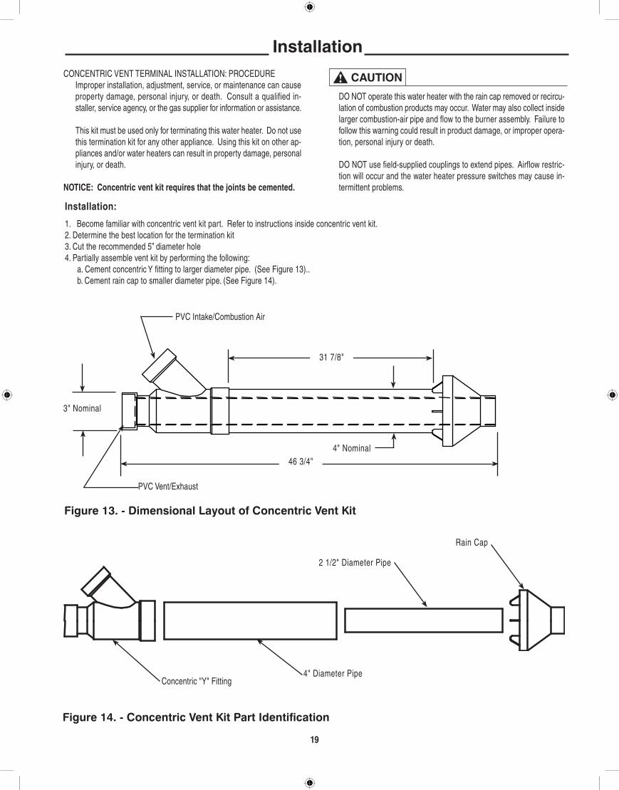
CONCENTRIC VENT TERMINAL INSTALLATION: PROCEDURE Improper installation, adjustment, service, or maintenance can cause
property damage, personal injury, or death. Consult a qualified in-staller, service agency, or the gas supplier for information or assistance.
This kit must be used only for terminating this water heater. Do not use this termination kit for any other appliance. Using this kit on other ap-pliances and/or water heaters can result in property damage, personal injury, or death.
NOTICE: Concentric vent kit requires that the joints be cemented .
DO NOT operate this water heater with the rain cap removed or recircu-lation of combustion products may occur. Water may also collect inside larger combustion-air pipe and flow to the burner assembly. Failure to follow this warning could result in product damage, or improper opera-tion, personal injury or death.
DO NOT use field-supplied couplings to extend pipes. Airflow restric-tion will occur and the water heater pressure switches may cause in-termittent problems.
CAUTION!
installation
Installation:
1. Become familiar with concentric vent kit part. Refer to instructions inside concentric vent kit.2. Determine the best location for the termination kit3. Cut the recommended 5” diameter hole4. Partially assemble vent kit by performing the following: a. Cement concentric Y fitting to larger diameter pipe. (See Figure 13).. b. Cement rain cap to smaller diameter pipe. (See Figure 14).
PVC Intake/Combustion Air
4" Nominal
31 7/8"
46 3/4"
PVC Vent/Exhaust
3" Nominal
Concentric "Y" Fitting4" Diameter Pipe
2 1/2" Diameter Pipe
Rain Cap
Figure 13. - Dimensional Layout of Concentric Vent Kit
Figure 14. - Concentric Vent Kit Part Identification

20
installation
Install concentric Y fitting and pipe assembly through the structure’s hole and field-supplied roof boot/flashing. Do not allow insulation or other materials to accumulate inside pipe assembly when installing through the hole. 6.
Secure assembly to roof structure as shown in Figure 16 using field-supplied metal strapping or equivalent support material.
NOTICE Ensure termination height is above the roof surface or antici-pated snow level. Figure 16.
If assembly is too short to meet height requirements, the two pipes supplied in the kit may be replaced by using the same diameter pipe. DO NOT extend the overall dimension by more than 60 inches. See Fig. 15.
Install rain cap and small diameter pipe assembly in roof penetration assembly. Ensure small diameter pipe is cemented and bottomed in Y concentric fitting.
Cement heater combustion-air and vent pipes to concentric y fitting assembly (Figure 13). See Figure 16 for proper pipe attachment.
Operate heater through one cycle to ensure combustion-air and vent pipes are properly connected and sealed to concentric vent termination connections.
Horizontal Installation: 1. Become familiar with coaxial vent kit part no. SP20261 for CAN &
US. As shown in Figures 14 through 16. 2. Determine the best location for the termination kit.
Clearance above highest antici-pated snow level.
Roof boot/flashing (Field Supplied)
Support (Field Supplied)
Combustion Air Vent
All joints must be sealed with PVC Cement.
Figure 15 - Rain Cap to Small Vent Pipe Assembly
Figure 16 - Concentric Vent Roof Top Attachment

21
NOTICE: Position termination where vent vapors will not damage plants/shrubs or air conditioning equipment. NOTICE: Position termination where vent vapors will not be adversely affected by wind condition.NOTICE: Position termination where it will not be damaged or be subjected to foreign objects. Position termination where vapors will not be objectionable.
Cut the recommended 5” diameter hole.
Partially assembled vent kit. a. Cement Y concentric fitting to larger diameter kit pipe. (See Figure
14). b. Cement rain cap to smaller diameter kit pipe. (See Figure 16).
Install concentric Y fitting and pipe assembly through the structure’s hole and field-supplied roof boot/flashing. Do not allow insulation or other materials to accumulate inside pipe assembly when installing through the hole.
Install rain cap and small diameter pipe assembly in concentric Y fitting and large pipe assembly. Ensure small diameter pipe is cemented and bottomed in concentric Y fitting.
Secure assembly to structure as shown in Figure 17. Ensure clearances as shown in Figure 17.
Cement heater combustion-air and vent pipes to concentric Y fitting ter-mination assembly.
Operate heater through one cycle to ensure combustion-air and vent pipes are properly connected and sealed to concentric vent termination con-nections.
Strap (Field Supplied)
Elbow (Field Supplied)
Combustion Air
Roof Overhang
Combustion Air
Vent
Vent
All joints must be sealed with PVC Cement Maintain 12" Clearance above highest anticipated snow level or grade which-ever is greater.
NOTICE: Strap must be field installed to prevent movement of vent terminal in wall.
Support Strap (Every 3' Min.)
12" Minimum1" Max.
Figure 17. Concentric Vent Side Wall Attachment
installation
36" Min. 36" Min.

22
A. Water Heater Location
❑Close to area of vent.
❑Indoors and protected from freezing temperatures.
❑Proper clearance from combustible surfaces observed and water heater not installed on carpeted floor.
❑Air supply free of corrosive elements and flammable vapors.
❑Provisions made to protect area from water damage.
❑Sufficient room to service heater.
B. Water Supply
❑Water heater completely filled with water.
❑Water heater and piping air vented.
❑Water connections tight and free of leaks.
C. Gas Supply ❑Gas line equipped with shut-off valve, union, and sediment trap/drip
leg. ❑Approved pipe joint compound used.
❑ Soap and water solution used to check all connections and fittings for possible gas leak.
❑Gas Company inspected installation (if required).
D. Relief Valve
❑Discharge line run to open drain.
❑Discharge line protected from freezing.
E. Venting
❑All pipe connections are secure (at blower, vent terminals and for each pipe joint connection)
❑Vent terminals mounted properly and in correct location.
F. Condensate ❑Condensate trap installed and primed.
installation Check list
TABlE 2For U.S. installations
maximum Capacity of Pipe in Cubic Feet of gas per hour for gas Pressures of0.5 psig or less and a Pressure Drop of 0.3 inch Water Column
Based on a 0.60 Specific gravity Natural gas; if 1.5 Specific gravity l.P. gas is used, multiply capacity by 0.63
Nominal internal iron Pipe Size, Diameter inches inches 10 20 30 40 50 60 70 80 90 100 125 150 175 200 1/2 .622 132 92 73 63 56 50 46 43 40 38 34 31 28 26 3/4 .824 278 190 152 130 115 105 96 90 84 79 72 64 59 55 1 1.049 520 350 285 245 215 195 180 170 160 150 130 120 110 100 1 1/4 1.380 1,050 730 590 500 440 400 370 350 320 305 275 250 225 210 1 1/2 1.610 1,600 1,100 890 760 670 610 560 530 490 460 410 380 350 320 2 2.067 3,050 2,100 1,650 1,450 1,270 1,150 1,050 990 930 870 780 710 650 610 2 1/2 2.469 4,800 3,300 2,700 2,300 2,000 1,850 1,700 1,600 1,500 1,400 1,250 1,130 1,050 980 3 3.068 8,500 5,900 4,700 4,100 3,600 3,250 3,000 2,800 2,600 2,500 2,200 2,000 1,850 1,700 4 4.026 17,500 12,000 9,700 8,300 7,400 6,800 6,200 5,800 5,400 5,100 4,500 4,100 3,800 3,500
Length of Pipe, Feet
22
maximum Pipe Capacity for installations in Canada, refer to CAN/CSA B149.1. For Natural Gas see Tables A.1 to A.17 For Propane (LP) Gas see Tables B.1 to B.12

23
WARNING: If you do not follow these instructions exactly, a fire or explosion mayresult causing property damage, personal injury or loss of life
This appl iance is equipped with an igni t iondevice which automatically lights the burner. DONOT try to light the burner by hand.
A .
BEFORE OPERATI NG smel l a l l around theappliance area for gas. Be sure to smell next tothe floor because some gas is heavier than airand will settle on the floor.
B .
WHAT TO DO IF YOU SMELL GAS• Do not try to light any appliance• Do not touch any electrical switch; do not use any phone in your building.• Immediately cal l your gas suppl ier from a neighbor's phone. Follow the gas supplier's instructions.
• If you cannot reach your gas supplier, call the fire department.
Use only your hand to turn the gas control knob.Never use tools. If the knob will not turn by hand,don't try to repair it, call a qualified servicetechnician. Force or attempt to repair may resultin a fire or explosion.
C .
Do not use this appliance if any part has beenunder water. Immediately call a qualified ser-vice technician to inspect the appliance and toreplace any part of the control system and anygas control which has been under water.
D .
2 .
OPERATING INSTRUCTIONS
TO TURN OFF GAS TO APPLIANCE
FOR YOUR SAFETY READ BEFORE OPERATING
SET THE “ON/OFF” SWITCH NEXT TO THECONTROL DISPLAY TO THE “OFF” POSI-TION.
3 . THIS APPLIANCE IS EQUIPPED WITH AN IGNITION DEVICE WHICH AUTOMATIC-ALLY LIGHTS THE BURNER.
4 . IF YOU THEN SMELL GAS, STOP! FOLLOW“B” IN THE SAFETY INFORMATION ABOVEON THIS LABEL. IF YOU DON’T SMELL GAS,GO TO THE NEXT STEP.
DO NOT TRY TO LIGHT THE BURNER BY HAND
5 . TURN ON ELECTRICAL POWER TO THEAPPLIANCE SWITCH LOCATED TO THE LEFTOF THE CONTROL DISPLAY.
6 . IF THE APPLIANCE WILL NOT OPERATE, FOLLOW THE INSTRUCTIONS “TO TURNOFF GAS TO APPLIANCE”.
7 . WATER TEMPERATURE ADJUSTMENT ISAPPROXIMATELY 120˚ F. SET THE THER-MOSTAT TO THE DESIRED TEMPERATURESETTING.
CAUTION: HOTTER WATER INCREASES THE RISK OF SCALD INJURY. CONSULT THE INSTRUCTION MANUAL BEFORECHANGING TEMPERATURE.
WARNING: TURN OFF ALL ELECTRICPOWER BEFORE SERVICING.
TURN OFF ALL ELECTRIC POWER TO THE APPLI-ANCE IF SERVICE IS TO BE PERFORMED.
1. TURN THE “MANUAL GAS VALVE KNOB”TO THE “OFF” POSITION.
2.
AX4904
STOP! READ THE SAFETY INFORMATIONABOVE ON THIS LABEL.
1 .
23
OperationBefore operating this water heater, be sure to read and follow the instructions on the label pictured below and all other labels on the water heater, as well as the warnings printed in this manual. Failure to do so can result in unsafe operation of the water heater resulting in property damage, bodily injury, or death. Should you have any problems reading or following the instructions in this manual, STOP, and get help from a qualified person.

24
1. TEMPERATURE SETTINGS — The temperature is adjusted to120° F when shipped from the factory. To meet commercial water use needs, it is adjustable up to 185°F (85°C). However, water temperatures over 125°F (52°C) can cause severe burns instantly or death from scalds. This is the preferred starting point for setting the control for supplying general purpose hot water.
Safety and energy conservation are factors to be considered when setting the water temperature. The most energy efficient operation will result when the temperature setting is the lowest that satisfies the needs consistent with the application.
hotter water increases the Potential for hot Water SCAlDS.
When this water heater is supplying general purpose hot water requirements for individuals, a thermostatically controlled mixing valve for reducing point of use water temperature is recommend-ed. Contact a licensed plumber or the local plumbing authority for further information.
Outlet water temperature will vary during normal operating cycles. Reli-able temperature readings should be taken shortly after main burner cycles off during a period of little or no use.
2 CHECK INPUT — Consult the local Gas Company to determine the heating value of the gas supplied. Check input by clocking gas meter with all other gas appliances turned off. Use the following formula:
DO NOT exceed input shown on the water heater's rating plate! To insure accuracy for rating, clock enough cubic feet of gas so that the clocked time is at least 60 seconds.
DO NOT exceed input shown on the water heater's rating plate!
4. EMERGENCY SHUTDOWN —
Should overheating occur or the gas supply fail to shut off, turn off the manual gas control valve to the appliance.
DO NOT use this appliance if any part has been under water. immediately call a qualified service technician to inspect the appli-ance and to replace any part of the control system and any gas control which has been under water.
If the water heater has been subjected to fire or physical damage, turn off gas at the manual gas control (shut-off) valve. Do not operate the water heater again until it has been checked out by a qualified service technician.
Operation
A. Do turn off manual gas shut-off valve if water heater has been sub-jected to over heating, fire, flood, physical damage or if gas supply fails to shut off.
B. Do Not turn on water heater unless it is filled with water.C. Do Not turn on water heater if cold water supply shut-off valve is
closed.D. Do Not store or use gasoline or other flammable vapors and liq-
uids, such as adhesives or paint thinner, in vicinity of this or any other appliance. If such flammables must be used, open doors and windows for ventilation, and all gas burning appliances in vicinity should be shut off, including their pilot lights, to avoid vapors ignit-ing.
NOTICE: Flammable vapors may be drawn by air currents from sur-rounding areas to the water heater.
E. Do not allow combustible materials such as newspaper, rags or mops to accumulate near water heater.
F. If there is any difficulty in understanding or following the OPERA-TION or MAINTENANCE instructions, it is recommended that a qualified person or serviceman perform the work.
hydrogen gas can be produced in a hot water system served by this water heater that has not been used for a long period of time (generally two weeks or more). hYDRO-gEN gAS iS ExTREmElY FlAmmABlE!! To dissipate such gas and to reduce risk of injury, it is recommended that the hot water faucet be opened for several minutes at the kitchen sink before using any electrical appliance connected to the hot water system. if hydrogen is present, there will probably be an unusual sound such as air escap-ing through the pipe as the water begins to flow. Do not smoke or use an open flame near the faucet at the time it is open.
SAFETY PRECAUTIONS
CAUTION!
INPUT (btu/h) = (3,600) x (Heating Value) x (Number of Cubic Feet Timed)
Seconds Clocked
DANGER!
WARNING!
WARNING!
WARNING!
WARNING!

25
Overview of the functionality provided by each button of the user interface.
MENU: To enter user menu mode for access to Tempera-tures, Heater Status, and Heater Information.
UP/DN: To navigate through heater menus for adjustment of settings.
OK: To confirm storage of adjustments to system settings.
HELP: Access to heater information in the event of a system fault.
DISPLAY WINDOW: Provides information as changes are made to control.
User interface
MENU: To enter user menu mode for access to Temperatures, Heater Status, and Heater Infor-mation.
HELP: Access to heater information in the event of a system fault.
OK: To confirm storage of adjustments to system settings.
UP/DN: To navigate through heater menus for adjustment of settings..
DISPLAY WINDOW: Provides information as changes are made to control.
Figure 11 - User Interface

26
User interface
Temperature Adjustment :
Enter Menu Mode by pressing the “MENU” button on the LCD interface screen, see Figure 11.
Press the UP or DN button to move the arrow to the Temperatures header. Press OK to enter the Temperatures submenu, see Figure 12.
Figure 12 Menu Mode
Figure 13 Temperatures Menu Press the MENU button to return to MAIN MENU screen.
Water Temperature Setting
To adjust the water temperature set point, press the OK button. The Set Point value will begin blinking( see Figure 13 above ). Press the UP or DN buttons to change the value of the Set Point. Press the OK button to confirm
the setting. The interface automatically moves to the next adjustable parameter (Differential setting) wherein such parameter will begin blinking.

27
Properly maintained, this water heater will provide years of dependable, trouble free service. It is strongly suggested that a regular routine mainte-nance program be established and followed by the owner. It is further rec-ommended that a periodic inspection of the relief valve and venting system should be made by service technicians qualified in gas appliance repair.
1. ROUTINE PREVENTIVE MAINTENANCE
A. PRESSURE SWITCH — Inspect the inlet to the pressure switch and the tubing for debris or blockage. Clean out the tubing periodically to prevent buildup of debris.
B COLLECTOR PAN —Remove any particles.
C. CONDENSATE TRAP — Check for blockages.
D. ELECTRICAL CONNECTIONS — Periodic inspection of all electrical connections and wiring conditions.
label all wires prior to disconnection when servicing con-trols. Wiring errors can cause improper and dangerous op-eration.
VERiFY PROPER OPERATiON AFTER SERViCiNg !
make certain all power to the water heater is turned "OFF" before performing any maintenance or inspec-tion work on this water heater.
Before manually operating the relief valve, make certain no
one will be exposed to the danger of coming in contact with the hot water released by this valve. The water may be hot enough to create a SCAlD hazard. The water released should be directed to a suitable drain to prevent injury or damage.
NOTICE: If the temperature and pressure relief valve on the water heater discharges periodically, this may be due to thermal expansion in a “closed” water system. Contact the water supplier or local plumbing inspector on how to correct this. DO NOT plug the relief valve outlet.
E. TANK— Good maintenance requires that the tank be cleaned of de-posits. Unless the water supply is soft (0 to 5 grains hardness), scale or lime deposits will accumulate in the tank. Hard water scale is de-posited at an increasingly high rate in proportion to increased water temperature. Accumulation of these deposits may reduce efficiency, and shorten the life of the water heater.
Any new installation should have a tank inspection program set up initially for frequent inspection. The first inspection should be within a six month period. Once the scaling tendencies have been established, the inspection program can be modified to suit the water conditions.
Cleaning should be performed if the scale has accumulated above the drain valve opening.
A wet-dry shop vac with a nozzle fashioned from 1” and/or 3/4” poly-ethylene pipe makes a good tool for scraping and removing scale.
TO CLEAN OR INSPECT TANK:
1. Shut off gas valve and drain tank.
2. Remove tank clean-out cover on jacket and with pocket knife cut and remove a circular plug of insulation the full size of jacket open-ing.
3. Loosen nut on seal plate assembly enough to twist yoke sideways. Hold assembly securely and push inward, then remove from tank.
4. Remove as much built-up scale from flue tubes and tank bottom as practical. Do not attempt to clean so thoroughly that the tool used damages the glass lining.
5. Clean the seal plate and install a new gasket. Wipe clean the interior surface of the tank that contacts the gasket. Reinstall the seal plate and tighten in position. Fill tank with water and check for leaks. If no leaks are found, install insulation plug and clean-out cover on jacket and re-light the water heater.
If chemical lime dissolving cleaners are preferred, cautiously follow the instructions supplied with the cleaner. DO NOT use a muriatic or hydrochloric acid (HCl) base cleaner.
2. ANODE INSPECTION — The water supply in certain areas contains very aggressive elements. In these areas, periodic inspection of the anode is recommended to determine if replacement is necessary. The anode(s) supplied in this water heater is slowly consumed , thereby eliminating or minimizing corrosion and protecting the glass lined tank. The anode(s) should be replaced when more than 6 inches (15 cm) of core wire is exposed at either end.
3. SEASONAL OPERATION - If the water heater is to remain idle for an extended period (60 days or more) the heater should be turned off. The water heater and piping should be drained if they might be subjected to freezing temperatures. It is recommended that the water heater's operation is thoroughly checked (by a qualified service technician) be-fore it is placed back in service. NOTICE: Refer to the Hydrogen Gas caution notation on page 24.
F. VENTING SYSTEM — Inspect venting system at least yearly to make certain the passageways are free and unobstructed, and that the vent connector from the water heater’s blower assembly is properly posi-tioned and securely attached. Remove any obstructions in vent con-nector or vent terminal.
maintenance
CAUTION!
CAUTION!

Before You Call For Service…Troubleshooting TipsSave time and money! Review the charts on the following pages first and you may not need to call for service.
Problem Possible Causes What To DoDisplay not on Is there power to unit? Verify that there is 120 Vac to Control Board.
Is display not completely installed? Make sure that the two pins on the back of the display are inserted into circuit board.
Is harness from control board connected? Make sure that wire harness from Control Board is still connected.
Blower does not run No power to blower motor. Verify power to Control Board and that all harnesses to the blower are properly installed. Make sure that there is no damage to harness or connectors.
Unable to lightthe main burner
Air in gas line. Let the unit cycle at least three times to remove air from gas line. If unit does not try to light, contact a qualified service technician to purge the air from the gas line.
Manual Gas Shut-offvalve(s) not open.
Check to make sure that all manual gas shut-off valves between unit and gas line are open.
Blocked Inlet or ExhaustVent pipe.
Contact a qualified Service Technician to evaluate vent pipes for blockage.
Pressure Switch. Make sure the pressure switch hoses are not "kinked" or disconnected.
Blocked inlet or outlet vent systems will cause pressure switch to shut off unit. Contact a qualified Service Technician to evaluate vent system.
Wire Connection not fullysecured.
Contact a qualified service technician to confirm wire connections.
If the screen on the display is flashing, the burner did not light. To reset the ignition sequence, press the "HELP" button and then the "OK" button (see Display screen at left). On initial startup, it might be necessary to clear the "flashing" screen two or three times, to make sure that the gas has made its way to the burner. If the unit has been operating and then shows the flashing display, then there is another issue to be resolved (unless gas has been off).
Some basic trouble codes:A01: burner did not light during three consecutive trials for ignition.A25: pressure switch did not close.A26: pressure switch was not open on initial check.E21: incorrect polarity on power supply.
28
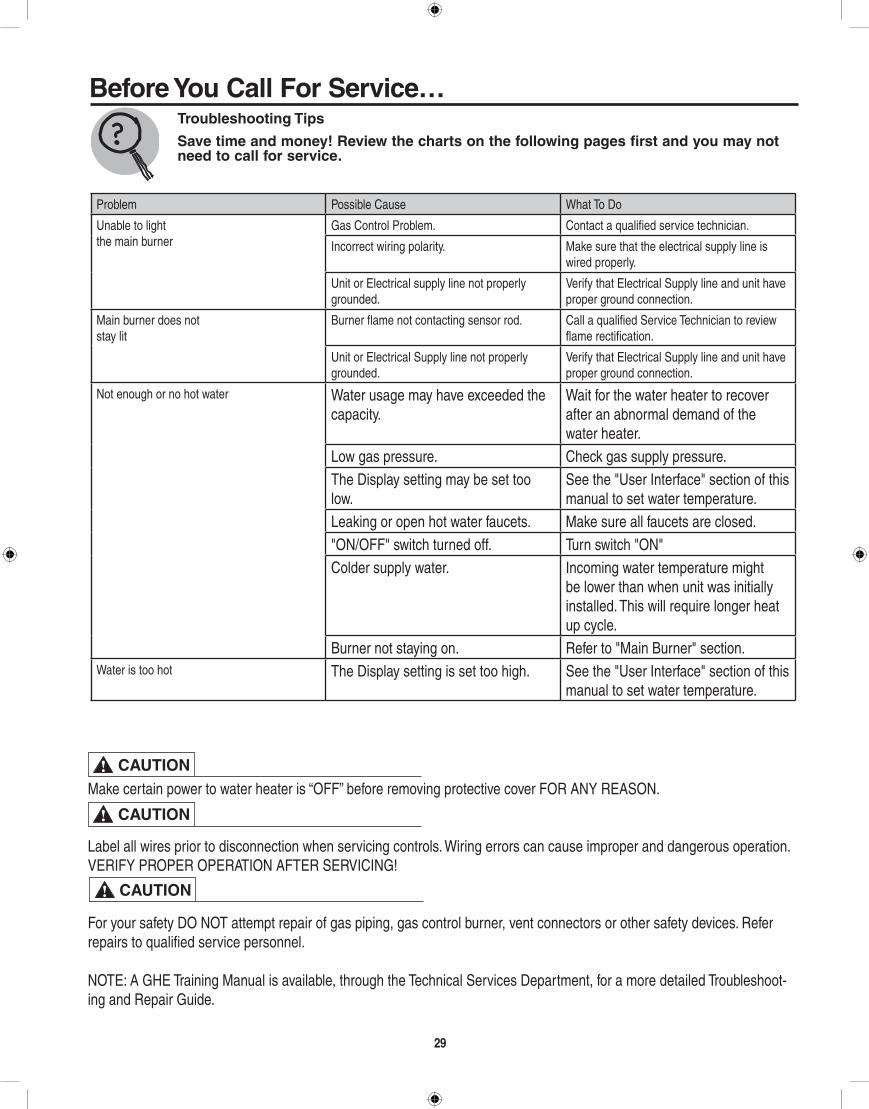
Problem Possible Cause What To Do
Unable to lightthe main burner
Gas Control Problem. Contact a qualified service technician.
Incorrect wiring polarity. Make sure that the electrical supply line is wired properly.
Unit or Electrical supply line not properly grounded.
Verify that Electrical Supply line and unit have proper ground connection.
Main burner does notstay lit
Burner flame not contacting sensor rod. Call a qualified Service Technician to review flame rectification.
Unit or Electrical Supply line not properly grounded.
Verify that Electrical Supply line and unit have proper ground connection.
Not enough or no hot water Water usage may have exceeded the capacity.
Wait for the water heater to recover after an abnormal demand of the water heater.
Low gas pressure. Check gas supply pressure.The Display setting may be set too low.
See the "User Interface" section of this manual to set water temperature.
Leaking or open hot water faucets. Make sure all faucets are closed."ON/OFF" switch turned off. Turn switch "ON"Colder supply water. Incoming water temperature might
be lower than when unit was initially installed. This will require longer heat up cycle.
Burner not staying on. Refer to "Main Burner" section.Water is too hot The Display setting is set too high. See the "User Interface" section of this
manual to set water temperature.
29
Make certain power to water heater is “OFF” before removing protective cover FOR ANY REASON.
Label all wires prior to disconnection when servicing controls. Wiring errors can cause improper and dangerous operation. VERIFY PROPER OPERATION AFTER SERVICING!
For your safety DO NOT attempt repair of gas piping, gas control burner, vent connectors or other safety devices. Refer repairs to qualified service personnel.
NOTE: A GHE Training Manual is available, through the Technical Services Department, for a more detailed Troubleshoot-ing and Repair Guide.
CAUTION!
CAUTION!
CAUTION!
Before You Call For Service…Troubleshooting Tips
Save time and money! Review the charts on the following pages first and you may not need to call for service.
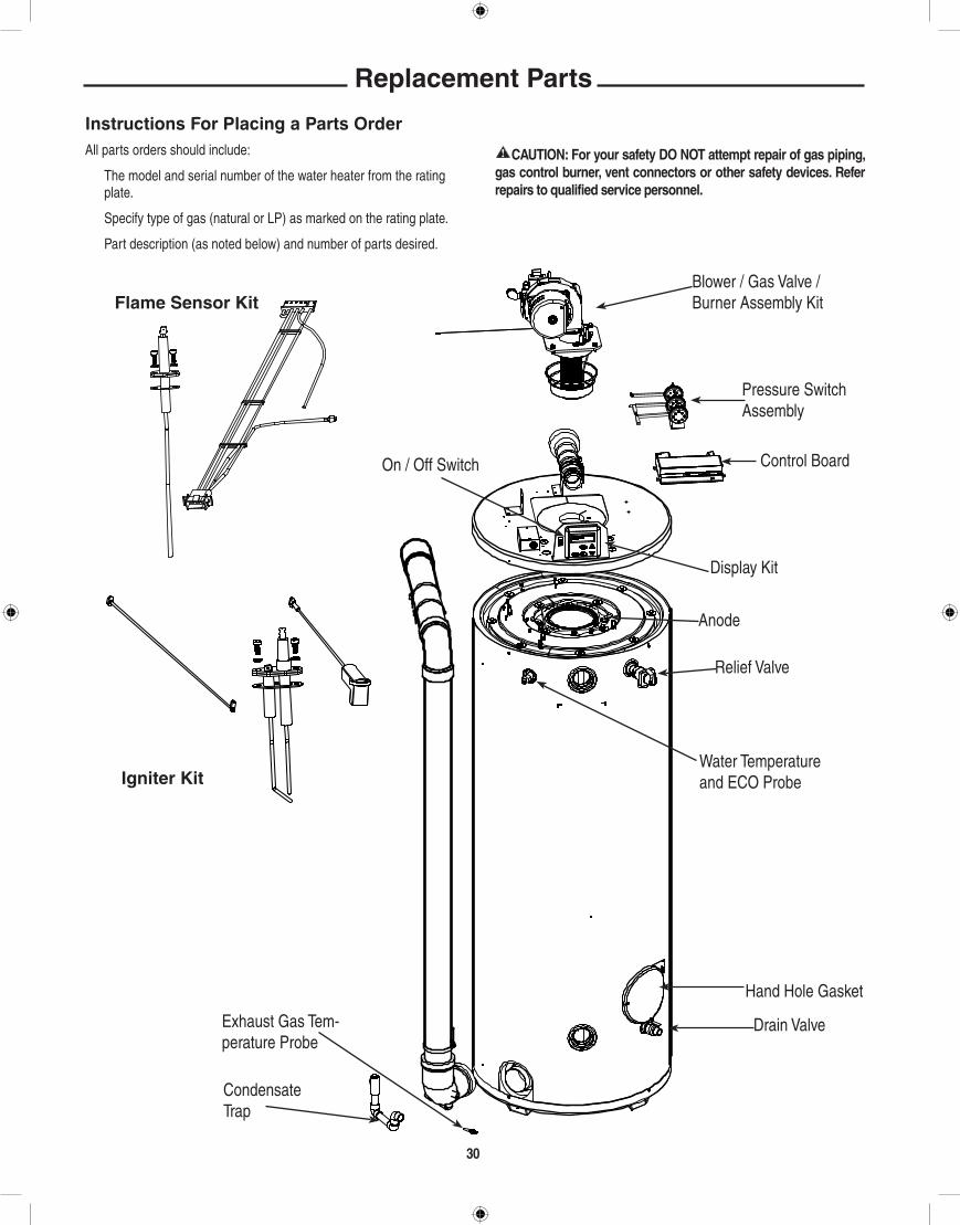
3030
Replacement Parts
Instructions For Placing a Parts OrderAll parts orders should include:
The model and serial number of the water heater from the rating plate.
Specify type of gas (natural or LP) as marked on the rating plate.
Part description (as noted below) and number of parts desired.
! CAUTiON: For your safety DO NOT attempt repair of gas piping, gas control burner, vent connectors or other safety devices. Refer repairs to qualified service personnel.
Flame Sensor KitBlower / Gas Valve / Burner Assembly Kit
Control Board
Pressure Switch Assembly
Anode
Display Kit
Relief Valve
Water Temperature and ECO Probe
Condensate Trap
Hand Hole Gasket
Drain ValveExhaust Gas Tem-perature Probe
On / Off Switch
igniter Kit

3131
Wiring and Schematic Diagrams
label all wires prior to disconnection when servicing controls. Wiring errors can cause improper and dangerous operation VERiFY PROPER OPERATiON AFTER SERViCiNg!
CAUTION!
J13
1K
J16
BKBK
PKPK
BKBK
YLYL
BRBR
RDRD
J16
J5J5
J5
J5J5
J5J5
J5J5
J14
J1
S4ONOFF
ARGUS LINE/PC CONNECTION
ARGUS LINEBUS POWER
PROGRAMMING HEADER
PROGRAMMING JUMPER
SAFETY LIMIT(ECO)
FLUE
BLOCKED INTAKE/EXHAUSTSWITCHES
AIR FLOWPROVING SWITCH
AIR FLOWPROVING SWITCH
TEMPERATUREPROBE
EXTERNALDISPLAY
IONIZATIONIGNITION
SPARKRETURN
IGNITER CABLE
BURNER
BLOWER
JUMPER
GAS VALVE
120VAC 60Hz
ONOFF
SAFETY LIMIT(ECO)
FLUE
BLOCKED INTAKE/EXHAUST SWITCHES
TEMPERATUREPROBE
EXTERNALDISPLAY
IONIZATIONIGNITION
SPARKRETURN
L N GN
IGNITER CABLE
BURNER
BLOWER
JUMPER
GAS VALVE
120VAC 60Hz
J18J18 J2
J2J2
J13J13
J13
J13J13
J9
J9J9
J12
T2
YL
OR
GN GN
GNBKW
BL
YLYL
BK
BK
W
W
GN
GN
GN
LN
1K
J5
CONNECTION DIAGRAM
IMPORTANTAC POLARITY
L - LINE N - NEUTRAL GN - GROUND
SCHEMATICIF ANY OF THE ORIGINAL WIRE AS SUPPLIED WITH THIS APPLIANCE MUST BEREPLACED, IT MUST BE REPLACED WITH 18 GA., 600V, 105°C WIRE OR ITSEQUIVALENT. AX4912-1
Size: 5.5” x 6.5”, 1/8” CRColors: Black on White
Approved By:
32
The following Gaskets are required for Normal Maintenance for all Models:
SP5886 Tank Handhole Sealplate Gasket
All other Parts can be ordered by providing the following information:
1. Description of Part(s), such as: Gas Valve Igniter Burner Switch/Sensor Blower Assembly Anode Rod Or other parts as required (see replacement parts section). 2. Quantity of each part required. 3. Complete model number and name of the water heater. 4. Serial Number of water heater. 5. Specify Type of Gas. 6. Address Parts Orders to your distributor or dealer.
1. Should you have any questions about your new water heater, or if it requires adjustment, repair, or routine maintenance, it is suggested that you first contact your installer, plumbing contrac-tor or previously agreed upon service agency. In the event that the firm has moved, or is unavailable, refer to the telephone directory commercial listings or local utility for qualified service assistance.
2. Should your problem not be solved to your complete satisfac-tion, you should then contact the Manufacturer’s National Ser-vice Department at one of the following address:
In The U.S.A.: Rheem Manufacturing Co., Water Heater Division 1241 Carwood Court Montgomery, Alabama 36117 Phone: 1-800-432-8373.
In CANADA: Rheem Canada, Ltd. / Ltée 125 Edgeware Road, Unit 1 Brampton, ON L6Y 0P5 Phone: 1-800-268-6966.
When contacting the manufacturer, the following information
should be made available:
a. Model and serial numbers of the water heater as shown on the rating plate attached to the jacket of the heater.
b. Address where water heater is located and can be seen.
c. Name and address of installer and any service agency who performed service on the water heater.
d. Date of original installation and dates any service work was performed.
e. Details of the problem as you can best describe them.
f. List of people, with dates, who have been contacted regarding your problem.
how to Obtain Service Assistance