Embed Size (px)
Citation preview

02/2006R1- Cod. 3225890 -
IMER INTERNATIONAL S.p.A.53036 POGGIBONSI (SIENA) loc. SALCETO
(ITALY)tel. 0577 97341 - fax 0577 983304
INTONACATRICEGUNITEUSE
MORTAR MIXERVERPUTZMASCHINE
ENFOSCADORA
( 1106045 )
Manuale uso manutenzione ricambi
Manuel utilisation entretien pièces de rechange
Operating, maintenance, spare parts manual
Handbuch für Bedienung, Wartung und Ersatzteile
Manual de uso, mantenimiento y recambios
EL
2
IMER INTERNATIONAL S.p.A.INTONACATRICI IMER
ENGLISH FRANÇAIS DEUTSCH ESPAÑOL
14
111012
13
5
8
7
1
1b
1a
2
2a
4a
4b
6
9
3
4
15
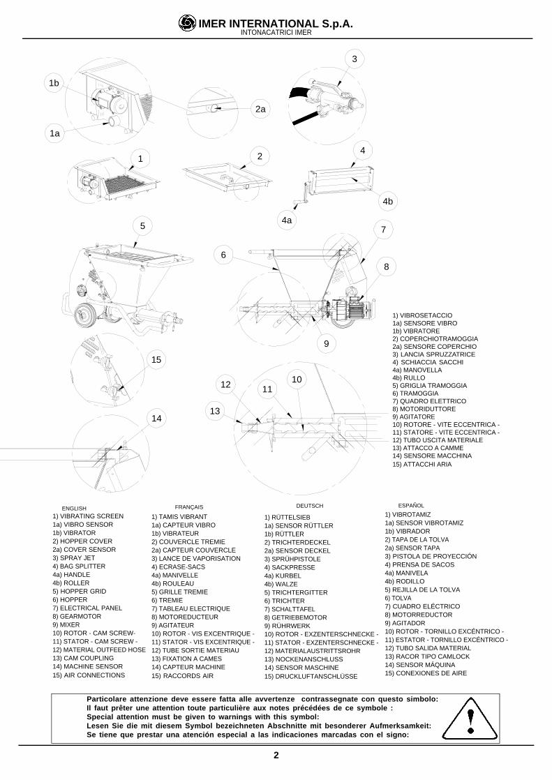
1) VIBROSETACCIO1a) SENSORE VIBRO1b) VIBRATORE2) COPERCHIOTRAMOGGIA2a) SENSORE COPERCHIO3) LANCIA SPRUZZATRICE4) SCHIACCIA SACCHI4a) MANOVELLA4b) RULLO5) GRIGLIA TRAMOGGIA6) TRAMOGGIA7) QUADRO ELETTRICO8) MOTORIDUTTORE9) AGITATORE10) ROTORE - VITE ECCENTRICA -11) STATORE - VITE ECCENTRICA -12) TUBO USCITA MATERIALE13) ATTACCO A CAMME14) SENSORE MACCHINA15) ATTACCHI ARIA
Particolare attenzione deve essere fatta alle avvertenze contrassegnate con questo simbolo:Il faut prêter une attention toute particulière aux notes précédées de ce symbole :Special attention must be given to warnings with this symbol:Lesen Sie die mit diesem Symbol bezeichneten Abschnitte mit besonderer Aufmerksamkeit:Se tiene que prestar una atención especial a las indicaciones marcadas con el signo:
1) TAMIS VIBRANT1a) CAPTEUR VIBRO1b) VIBRATEUR2) COUVERCLE TREMIE2a) CAPTEUR COUVERCLE3) LANCE DE VAPORISATION4) ECRASE-SACS4a) MANIVELLE4b) ROULEAU5) GRILLE TREMIE6) TREMIE7) TABLEAU ELECTRIQUE8) MOTOREDUCTEUR9) AGITATEUR10) ROTOR - VIS EXCENTRIQUE -11) STATOR - VIS EXCENTRIQUE -12) TUBE SORTIE MATERIAU13) FIXATION A CAMES14) CAPTEUR MACHINE15) RACCORDS AIR
1) RÜTTELSIEB1a) SENSOR RÜTTLER1b) RÜTTLER2) TRICHTERDECKEL2a) SENSOR DECKEL3) SPRÜHPISTOLE4) SACKPRESSE4a) KURBEL4b) WALZE5) TRICHTERGITTER6) TRICHTER7) SCHALTTAFEL8) GETRIEBEMOTOR9) RÜHRWERK10) ROTOR - EXZENTERSCHNECKE -11) STATOR - EXZENTERSCHNECKE -12) MATERIALAUSTRITTSROHR13) NOCKENANSCHLUSS14) SENSOR MASCHINE15) DRUCKLUFTANSCHLÜSSE
1) VIBRATING SCREEN1a) VIBRO SENSOR1b) VIBRATOR2) HOPPER COVER2a) COVER SENSOR3) SPRAY JET4) BAG SPLITTER4a) HANDLE4b) ROLLER5) HOPPER GRID6) HOPPER7) ELECTRICAL PANEL8) GEARMOTOR9) MIXER10) ROTOR - CAM SCREW-11) STATOR - CAM SCREW -12) MATERIAL OUTFEED HOSE13) CAM COUPLING14) MACHINE SENSOR15) AIR CONNECTIONS
1) VIBROTAMIZ1a) SENSOR VIBROTAMIZ1b) VIBRADOR2) TAPA DE LA TOLVA2a) SENSOR TAPA3) PISTOLA DE PROYECCIÓN4) PRENSA DE SACOS4a) MANIVELA4b) RODILLO5) REJILLA DE LA TOLVA6) TOLVA7) CUADRO ELÉCTRICO8) MOTORREDUCTOR9) AGITADOR10) ROTOR - TORNILLO EXCÉNTRICO -11) ESTATOR - TORNILLO EXCÉNTRICO -12) TUBO SALIDA MATERIAL13) RACOR TIPO CAMLOCK14) SENSOR MÁQUINA15) CONEXIONES DE AIRE
3
IMER INTERNATIONAL S.p.A.
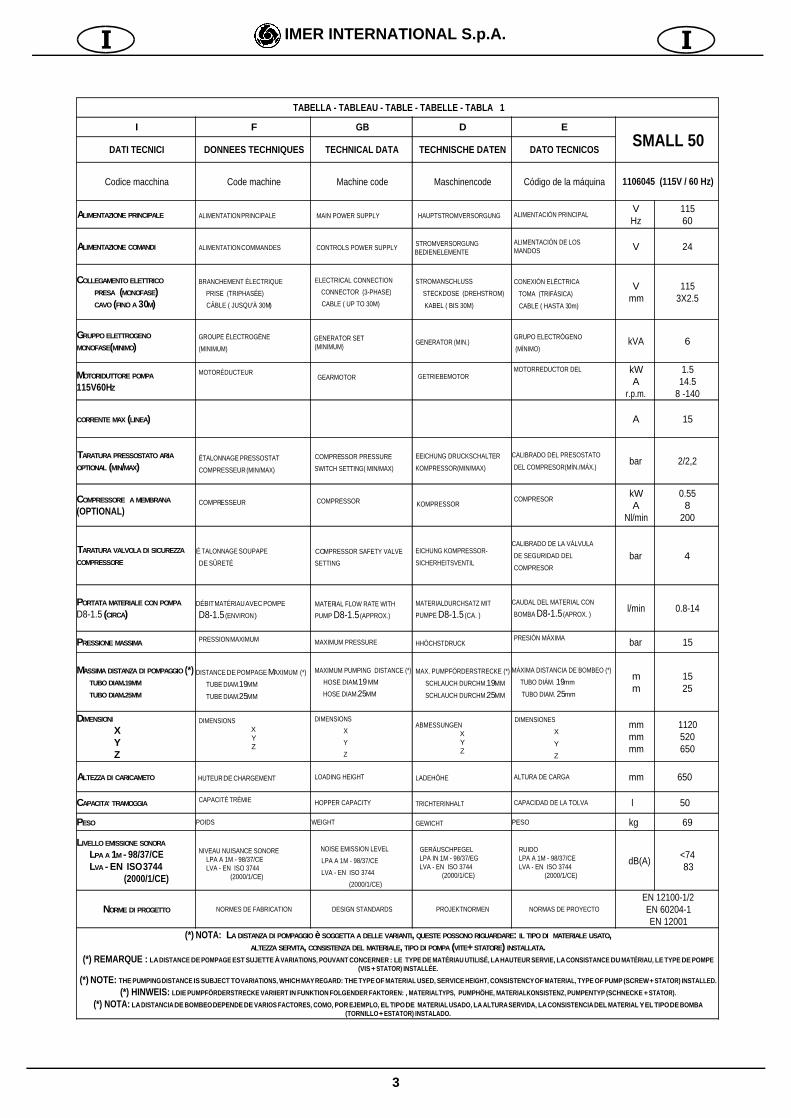
TABELLA - TABLEAU - TABLE - TABELLE - TABLA 1
I F GB D E
SMALL 50DATI TECNICI DONNEES TECHNIQUES TECHNICAL DATA TECHNISCHE DATEN DATO TECNICOS
Codice macchina Code machine Machine code Maschinencode Código de la máquina 1106045 (115V / 60 Hz)
ALIMENTAZIONE PRINCIPALE ALIMENTATION PRINCIPALE MAIN POWER SUPPLY HAUPTSTROMVERSORGUNG ALIMENTACIÓN PRINCIPALVHz
11560
ALIMENTAZIONE COMANDI ALIMENTATION COMMANDES CONTROLS POWER SUPPLY STROMVERSORGUNG BEDIENELEMENTE
ALIMENTACIÓN DE LOS MANDOS V 24
COLLEGAMENTO ELETTRICO
PRESA (MONOFASE) CAVO (FINO A 30M)
BRANCHEMENT ÉLECTRIQUE
PRISE (TRIPHASÉE)
CÂBLE ( JUSQU'À 30M)
ELECTRICAL CONNECTION
CONNECTOR (3-PHASE)
CABLE ( UP TO 30M)
STROMANSCHLUSS
STECKDOSE (DREHSTROM)
KABEL ( BIS 30M)
CONEXIÓN ELÉCTRICA
TOMA (TRIFÁSICA)
CABLE ( HASTA 30m)
Vmm
1153X2.5
GRUPPO ELETTROGENO
MONOFASE(MINIMO) GROUPE ÉLECTROGÈNE
(MINIMUM)
GENERATOR SET (MINIMUM)
GENERATOR (MIN.) GRUPO ELECTRÓGENO
(MÍNIMO)kVA 6
MOTORIDUTTORE POMPA
115V60HZ
MOTORÉDUCTEUR GEARMOTOR GETRIEBEMOTOR
MOTORREDUCTOR DEL kWA
r.p.m.
1.514.5
8 -140
CORRENTE MAX (LINEA) A 15
TARATURA PRESSOSTATO ARIA
OPTIONAL (MIN/MAX) ÉTALONNAGE PRESSOSTAT
COMPRESSEUR (MIN/MAX)
COMPRESSOR PRESSURE
SWITCH SETTING( MIN/MAX)
EEICHUNG DRUCKSCHALTER
KOMPRESSOR(MIN/MAX)
CALIBRADO DEL PRESOSTATO
DEL COMPRESOR(MÍN./MÁX.)bar 2/2,2
COMPRESSORE A MEMBRANA
(OPTIONAL) COMPRESSEUR COMPRESSOR KOMPRESSOR
COMPRESORkWA
Nl/min
0.558
200
TARATURA VALVOLA DI SICUREZZA
COMPRESSORE
É TALONNAGE SOUPAPE
DE SÛRETÉ
COMPRESSOR SAFETY VALVE
SETTING
EICHUNG KOMPRESSOR-
SICHERHEITSVENTIL
CALIBRADO DE LA VÁLVULA
DE SEGURIDAD DEL
COMPRESOR
bar 4
PORTATA MATERIALE CON POMPA
D8-1.5 (CIRCA)DÉBIT MATÉRIAU AVEC POMPE
D8-1.5 (ENVIRON )
MATERIAL FLOW RATE WITH
PUMP D8-1.5 (APPROX.)
MATERIALDURCHSATZ MIT
PUMPE D8-1.5 (CA. )
CAUDAL DEL MATERIAL CON
BOMBA D8-1.5 (APROX. )l/min 0.8-14
PRESSIONE MASSIMA PRESSION MAXIMUM MAXIMUM PRESSURE HHÖCHSTDRUCK PRESIÓN MÁXIMA bar 15
MASSIMA DISTANZA DI POMPAGGIO (*) TUBO DIAM.19MM
TUBO DIAM.25MM
DISTANCE DE POMPAGE MAXIMUM (*)
TUBE DIAM.19MM
TUBE DIAM.25MM
MAXIMUM PUMPING DISTANCE (*)
HOSE DIAM.19 MM
HOSE DIAM.25MM
MAX. PUMPFÖRDERSTRECKE (*)
SCHLAUCH DURCHM.19MM
SCHLAUCH DURCHM.25MM
MÁXIMA DISTANCIA DE BOMBEO (*)
TUBO DIÁM. 19mm
TUBO DIAM. 25mm
mm
1525
DIMENSIONI
X Y Z
DIMENSIONSXYZ
DIMENSIONS
X
Y
Z
ABMESSUNGENXYZ
DIMENSIONES
X Y Z
mmmmmm
1120520650
ALTEZZA DI CARICAMETO HUTEUR DE CHARGEMENT LOADING HEIGHT LADEHÖHE ALTURA DE CARGA mm 650
CAPACITA' TRAMOGGIA CAPACITÉ TRÉMIE HOPPER CAPACITY TRICHTERINHALT CAPACIDAD DE LA TOLVA l 50
PESO POIDS WEIGHT GEWICHT PESO kg 69
LIVELLO EMISSIONE SONORA
LPA A 1M - 98/37/CE LVA - EN ISO 3744
(2000/1/CE)
NIVEAU NUISANCE SONORE LPA A 1M - 98/37/CE LVA - EN ISO 3744 (2000/1/CE)
NOISE EMISSION LEVEL
LPA A 1M - 98/37/CE
LVA - EN ISO 3744
(2000/1/CE)
GERÄUSCHPEGEL LPA IN 1M - 98/37/EG LVA - EN ISO 3744 (2000/1/CE)
RUIDO LPA A 1M - 98/37/CE LVA - EN ISO 3744 (2000/1/CE)
dB(A)<74 83
NORME DI PROGETTO NORMES DE FABRICATION DESIGN STANDARDS PROJEKTNORMEN NORMAS DE PROYECTO
EN 12100-1/2EN 60204-1EN 12001
(*) NOTA: LA DISTANZA DI POMPAGGIO è SOGGETTA A DELLE VARIANTI, QUESTE POSSONO RIGUARDARE: IL TIPO DI MATERIALE USATO,ALTEZZA SERVITA, CONSISTENZA DEL MATERIALE, TIPO DI POMPA (VITE+ STATORE) INSTALLATA.
(*) REMARQUE : LA DISTANCE DE POMPAGE EST SUJETTE À VARIATIONS, POUVANT CONCERNER : LE TYPE DE MATÉRIAU UTILISÉ, LA HAUTEUR SERVIE, LA CONSISTANCE DU MATÉRIAU, LE TYPE DE POMPE(VIS + STATOR) INSTALLÉE.
(*) NOTE: THE PUMPING DISTANCE IS SUBJECT TO VARIATIONS, WHICH MAY REGARD: THE TYPE OF MATERIAL USED, SERVICE HEIGHT, CONSISTENCY OF MATERIAL, TYPE OF PUMP (SCREW + STATOR) INSTALLED.
(*) HINWEIS: LDIE PUMPFÖRDERSTRECKE VARIIERT IN FUNKTION FOLGENDER FAKTOREN: , MATERIALTYPS, PUMPHÖHE, MATERIALKONSISTENZ, PUMPENTYP (SCHNECKE + STATOR).
(*) NOTA: LA DISTANCIA DE BOMBEO DEPENDE DE VARIOS FACTORES, COMO, POR EJEMPLO, EL TIPO DE MATERIAL USADO, LA ALTURA SERVIDA, LA CONSISTENCIA DEL MATERIAL Y EL TIPO DE BOMBA(TORNILLO + ESTATOR) INSTALADO.
18
IMER INTERNATIONAL S.p.A.
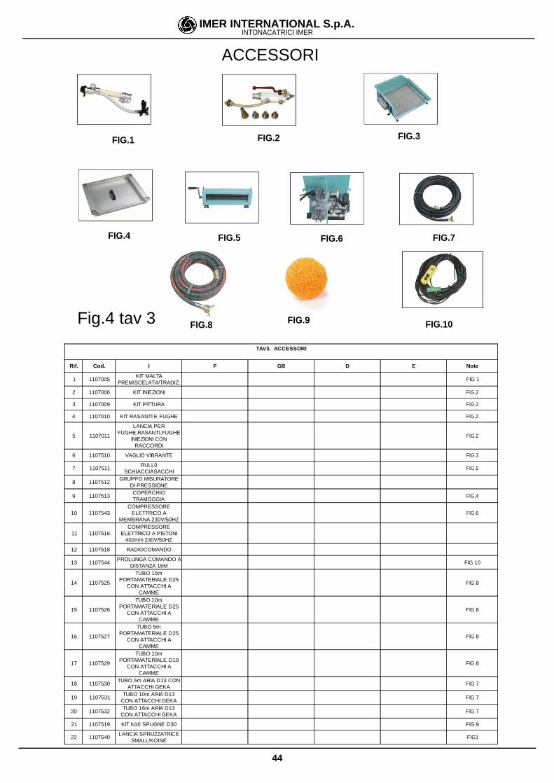
accessories, as described in paragraph 4.2.
4.2 DESCRIPTION OF MAIN ACCESSORIES REQUIREDFOR THE RANGE OF APPLICATIONSSMALL 50 is undoubtedly the smallest and most versatile pumpavailable. There are manifold applications in which this pumprepresents the ideal solution in terms of operation and speed. Bythe simple addition or replacement of an accessory, SMALL 50can be adapted to diverse requirements. For this reason, it isimportant to be aware of the wide range of accessories available,to enable full exploitation of the potential of this machine.IMER INTERNATIONAL is available, through their dealers andauthorised service centres to evaluate your requirements andfind the ideal solution.
Commonly used optional accessories (see fig.1):
- IMER VIBRO - SCREEN code no. 1107548
- This accessory replaces the hopper grid and istherefore equipped with a safety sensor.It must be used when the material is to be mixed on site withcollection of aggregate from a loose storage deposit: in thiscase some aggregate may have a larger particle size thanadmissible values, which could obstruct the spray outlet or causepremature wear of the statorAfter removing the hopper grid (ref.5), position the screen onthe hopper (ref. 6) and make the electrical connection with themachine s electrical panel (fig.5,ref. 12), fitted with the vibratoron/off control.Operation: after positioning and connecting the machine, andbefore pouring the material into the hopper, set the main switchto ON to start up the vibrator. Pour in the required material and oncompletion turn the switch to OFF, removing any residue trappedin the screen.
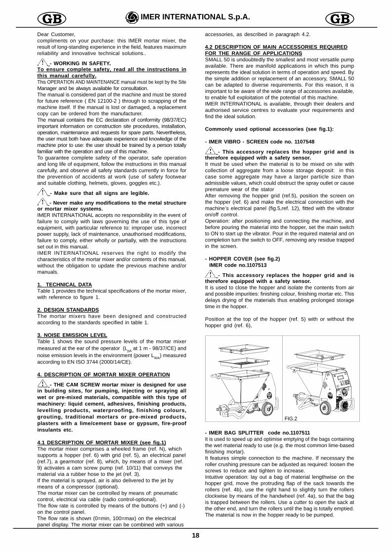
- HOPPER COVER (see fig.2) IMER code no.1107513
- This accessory replaces the hopper grid and istherefore equipped with a safety sensor.It is used to close the hopper and isolate the contents from airand possible impurities: finishing colour, finishing mortar etc. Thisdelays drying of the materials thus enabling prolonged storagetime in the hopper.
Position at the top of the hopper (ref. 5) with or without thehopper grid (ref. 6),
- IMER BAG SPLITTER code no.1107511It is used to speed up and optimise emptying of the bags containingthe wet material ready to use (e.g. the most common lime-basedfinishing mortar).It features simple connection to the machine. If necessary theroller crushing pressure can be adjusted as required: loosen thescrews to reduce and tighten to increase.Intuitive operation: lay out a bag of material lengthwise on thehopper grid, move the protruding flap of the sack towards therollers (ref. 4b), use the right hand to slightly turn the rollersclockwise by means of the handwheel (ref. 4a), so that the bagis trapped between the rollers. Use a cutter to open the sack atthe other end, and turn the rollers until the bag is totally emptied.The material is now in the hopper ready to be pumped.
Dear Customer,compliments on your purchase: this IMER mortar mixer, theresult of long-standing experience in the field, features maximumreliability and innovative technical solutions..
- WORKING IN SAFETY..
To ensure complete safety, read all the instructions inthis manual carefully.This OPERATION AND MAINTENANCE manual must be kept by the SiteManager and be always available for consultation.The manual is considered part of the machine and must be storedfor future reference ( EN 12100-2 ) through to scrapping of themachine itself. If the manual is lost or damaged, a replacementcopy can be ordered from the manufacturer.The manual contains the EC declaration of conformity (98/37/EC)important information on construction site procedures, installation,operation, maintenance and requests for spare parts. Nevertheless,the user must both have adequate experience and knowledge of themachine prior to use: the user should be trained by a person totallyfamiliar with the operation and use of this machine.To guarantee complete safety of the operator, safe operationand long life of equipment, follow the instructions in this manualcarefully, and observe all safety standards currently in force forthe prevention of accidents at work (use of safety footwearand suitable clothing, helmets, gloves, goggles etc.).
- Make sure that all signs are legible.
- Never make any modifications to the metal structureor mortar mixer systems.IMER INTERNATIONAL accepts no responsibility in the event offailure to comply with laws governing the use of this type ofequipment, with particular reference to: improper use, incorrectpower supply, lack of maintenance, unauthorised modifications,failure to comply, either wholly or partially, with the instructionsset out in this manual.IMER INTERNATIONAL reserves the right to modify thecharacteristics of the mortar mixer and/or contents of this manual,without the obligation to update the previous machine and/ormanuals.
1. TECHNICAL DATATable 1 provides the technical specifications of the mortar mixer,with reference to figure 1.
2. DESIGN STANDARDSThe mortar mixers have been designed and constructedaccording to the standards specified in table 1.
3. NOISE EMISSION LEVELTable 1 shows the sound pressure levels of the mortar mixermeasured at the ear of the operator (LpA at 1 m - 98/37/CE) andnoise emission levels in the environment (power LWA) measuredaccording to EN ISO 3744 (2000/14/CE).
4. DESCRIPTION OF MORTAR MIXER OPERATION
- THE CAM SCREW mortar mixer is designed for usein building sites, for pumping, injecting or spraying allwet or pre-mixed materials, compatible with this type ofmachinery: liquid cement, adhesives, finishing products,levelling products, waterproofing, finishing colours,grouting, traditional mortars or pre-mixed products,plasters with a lime/cement base or gypsum, fire-proofinsulants etc.
4.1 DESCRIPTION OF MORTAR MIXER (see fig.1)The mortar mixer comprises a wheeled frame (ref. N), whichsupports a hopper (ref. 6) with grid (ref. 5), an electrical panel(ref.7), a gearmotor (ref. 8), which, by means of a mixer (ref.9) activates a cam screw pump (ref. 10/11) that conveys thematerial via a rubber hose to the jet (ref. 3).If the material is sprayed, air is also delivered to the jet bymeans of a compressor (optional).The mortar mixer can be controlled by means of: pneumaticcontrol, electrical via cable (radio control-optional).The flow rate is controlled by means of the buttons (+) and (-)on the control panel.The flow rate is shown (0=min, 100=max) on the electricalpanel display. The mortar mixer can be combined with various
FIG.2
19
IMER INTERNATIONAL S.p.A.IMER MORTAR MIXERS
- Before using the mortar mixer, ensure that it is
fitted with all safety devices.
- Never insert parts of the body and/or tools in the
hopper .All current standards governing accident prevention and safetydevices must be observed in the workplace.Take care when handling bags of material, to avoid sprays whichmay come into contact with the eyes or other parts of the body.Wear safety goggles and gloves. Avoid the dispersion of dustwhich may be inhaled. Always wear a mouth and nose protectionmask during use.
- Never use the machine in areas subject to the risk of
explosion/fires or in underground installations.The mortar mixer is not equipped with a lighting system andtherefore the workplace must be fitted with adequate lighting.The power lines must be laid to prevent any possible damage.Never place the mortar mixer on electric power cables.Ensure that the electrical connection is protected against the riskof water penetration in connectors. Use exclusively connectorsand couplings equipped with water spray protection.- Never use inadequate or provisional electric lines; if in doubtconsult specialist personnel for assistance.- Repairs to the electrical circuit must be performed exclusivelyby specialised personnel. Disconnect the machine from the powersupply before performing maintenance or repairs.-Avoid contact of electric wires with movable and/or movingparts of the machine to avoid injury from contact with live metalparts.
6. ELECTRICAL SAFETYThe SMALL 50 mortar mixer is constructed according to standard EN60204-1, with protection against water sprays and protection againstoverload and power failure.The mortar mixer must be connected to the earthing circuit.
- Caution ! Keep hands away from the rollers when
turning to avoid the risk of fingers becoming trapped.
- IMER COMPRESSORS code no.1107546The air delivered by the compressor to the spray jet via a rubberhose is used to spray the pumped material. Compressors withdifferent air flow rates can be applied on the machine: from 180l/min to 600 l/min of air output. The selection of the type ofcompressor to be used is based on the type of material handledand the type of application. In general, the greater the air flowrate, the finer the material spray delivered.The 180 l/min compressor is suitable for most products which,after spraying on walls require manual distribution (thickapplications: plaster, grouting, finishing mortar etc...). Acompressor with greater output is required for all products, which,once sprayed uniformly onto the walls, do not need specialspreading operations, or which are only smoothed (thin layerapplications: levelling products, colours, some finishing mortars,waterproofing agents etc.).IMER code no.1107546, is an autonomous compressor. It isconnected to the site panel and the pneumatic circuit of themachine.
- Caution ! For installation, connections, operationand maintenance, refer to the compressor instructionmanual.
- This compressor is connected directly to the sitemains electrical panel.This enables machine start-up when the air line is open andshutdown when it is closed. The compressor is equipped withan auto-shutdown system, overload cut-out, and main switch,which lights up when the unit is powered.Maintenance: Check the air filters weekly, clean or replace whennecessary, above all if working in excessively dustyenvironments (see compressor operation and maintenancemanual).It is positioned in the vicinity of the mortar mixer and connecteddirectly to the spray jet hose.In this case the machine is turned on and off from the jet position,using the remote control supplied with the mortar mixer, or theoptional radio control.
- RADIO CONTROL code no.1107518Enables remote control of machine start-up/shutdown withelectrical cable connections.The receiver is installed in the electrical panel.The receiver is extremely practical; it can be held in the hand,pocket or fixed to the spray jet, outlet or other element by meansof magnets. To turn on the machine, press ON, and to shut downpress OFF.
- Caution ! Protect the unit from water jets; it mustnever get wet.
- PRESSURE GAUGE code no. 1107512This is a control instrument used to read pressure levels in thematerial hose lines.For example: in the case of using traditional mortar at the maximumflow rate of 100 on the panel display, and if pressure exceeds15 bar (maximum pump pressure). To prevent tripping of themachine protection devices, simply reduce the material flow rateby pressing the pushbutton (-) on the electrical panel, until thevalue falls below 15 bar.
5. OPERATION SAFETY
20
IMER INTERNATIONAL S.p.A.IMER MORTAR MIXERS
7. MECHANICAL SAFETYThe hazardous points on the IMER mortar mixer are protectedby means of suitable safety devices, which must remain fittedat all times and kept in perfect condition, such as the electricmotor cooling fan guard, the grid on the hopper, the vibro-screen and the hopper cover to prevent contact with the mixer.All elements are connected to a safety sensor: when disen-gaged, all moving parts of the machine are shut down.
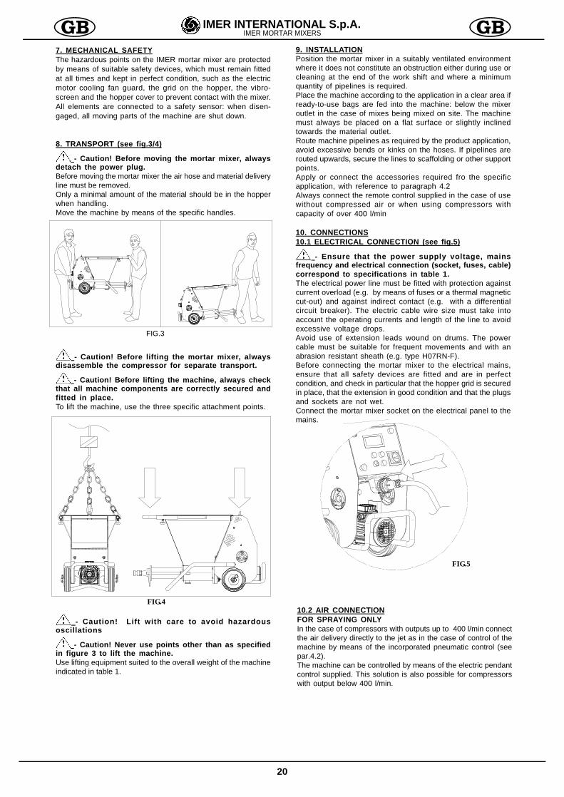
8. TRANSPORT (see fig.3/4)
- Caution! Before moving the mortar mixer, always
detach the power plug.Before moving the mortar mixer the air hose and material deliveryline must be removed.Only a minimal amount of the material should be in the hopperwhen handling.Move the machine by means of the specific handles.
- Caution! Before lifting the mortar mixer, alwaysdisassemble the compressor for separate transport.
- Caution! Before lifting the machine, always checkthat all machine components are correctly secured andfitted in place.To lift the machine, use the three specific attachment points.
- Caution! Lift with care to avoid hazardousoscillations
- Caution! Never use points other than as specifiedin figure 3 to lift the machine.Use lifting equipment suited to the overall weight of the machineindicated in table 1.
9. INSTALLATIONPosition the mortar mixer in a suitably ventilated environmentwhere it does not constitute an obstruction either during use orcleaning at the end of the work shift and where a minimumquantity of pipelines is required.Place the machine according to the application in a clear area ifready-to-use bags are fed into the machine: below the mixeroutlet in the case of mixes being mixed on site. The machinemust always be placed on a flat surface or slightly inclinedtowards the material outlet.Route machine pipelines as required by the product application,avoid excessive bends or kinks on the hoses. If pipelines arerouted upwards, secure the lines to scaffolding or other supportpoints.Apply or connect the accessories required fro the specificapplication, with reference to paragraph 4.2Always connect the remote control supplied in the case of usewithout compressed air or when using compressors withcapacity of over 400 l/min
10. CONNECTIONS10.1 ELECTRICAL CONNECTION (see fig.5)
- Ensure that the power supply voltage, mainsfrequency and electrical connection (socket, fuses, cable)correspond to specifications in table 1.The electrical power line must be fitted with protection againstcurrent overload (e.g. by means of fuses or a thermal magneticcut-out) and against indirect contact (e.g. with a differentialcircuit breaker). The electric cable wire size must take intoaccount the operating currents and length of the line to avoidexcessive voltage drops.Avoid use of extension leads wound on drums. The powercable must be suitable for frequent movements and with anabrasion resistant sheath (e.g. type H07RN-F).Before connecting the mortar mixer to the electrical mains,ensure that all safety devices are fitted and are in perfectcondition, and check in particular that the hopper grid is securedin place, that the extension in good condition and that the plugsand sockets are not wet.Connect the mortar mixer socket on the electrical panel to themains.
FIG.3
FIG.4
FIG.5
10.2 AIR CONNECTIONFOR SPRAYING ONLYIn the case of compressors with outputs up to 400 l/min connectthe air delivery directly to the jet as in the case of control of themachine by means of the incorporated pneumatic control (seepar.4.2).The machine can be controlled by means of the electric pendantcontrol supplied. This solution is also possible for compressorswith output below 400 l/min.
21
IMER INTERNATIONAL S.p.A.IMER MORTAR MIXERS
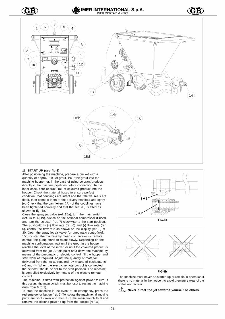
11. START-UP (see fig.6)After positioning the machine, prepare a bucket with aquantity of approx. 10l. of grout. Pour the grout into themachine hopper, or, in the case of using colorant products,directly in the machine pipelines before connection. In thelatter case, pour approx. 10l. of coloured product into thehopper. Check the material hoses to ensure perfectcondition, that couplings are intact and the relative seals arefitted, then connect them to the delivery manifold and sprayjet. Check that the cam levers ( A ) of the couplings havebeen tightened correctly and that the seal (B) is fitted asshown in fig. 6a.Close the spray jet valve (ref. 15a), turn the main switch(ref. 3) to 1(ON), switch on the optional compressor if used,and turn the selector (ref. 7) clockwise to the start position.The pushbuttons (+) flow rate (ref. 6) and (-) flow rate (ref.5), control the flow rate as shown on the display (ref. 8) at30. Open the spray jet air valve (or pneumatic control)(ref.15d) or start the machine by means of the electric remotecontrol: the pump starts to rotate slowly. Depending on themachine configuration, wait until the grout in the hopperreaches the level of the mixer, or until the coloured product isdelivered from the jet. At this point shut down the machine bymeans of the pneumatic or electric control, fill the hopper andstart work as required. Adjust the quantity of materialdelivered from the jet as required, by means of pushbuttons(+) and (-). When the electric remote control is connected,the selector should be set to the start position. The machineis controlled exclusively by means of the electric remotecontrol.The machine is fitted with protection against power failure: ifthis occurs, the main switch must be reset to restart the machine(turn from 0 to 1).To stop the machine in the event of an emergency, press thered emergency button (ref. 2) To isolate the machine, all movingparts are shut down and then turn the main switch to 0 andremove the electric power plug from the socket (ref.11).
1
3
79
2
10 12
11
6 5 4
1314
8
15a1515b
15c
15d
( A )
FIG.6b
( B )
FIG.6a
The machine must never be started up or remain in operation ifthere is no material in the hopper, to avoid premature wear of thestator and screw.
- Never direct the jet towards yourself or others
22
IMER INTERNATIONAL S.p.A.IMER MORTAR MIXERS
OVERLOAD AND ELECTRICAL PROTECTIONS
- The electric motors are protected against overload by
thermal magnetic cut-outs, the activation of which is indicated bytotal shutdown of the machine. In this case, after the motors havecooled, the specific personnel should reset the main switch toresume operation.
For the pump motor there is an additional safety protection: athermal sensor shuts down the machine in the event of a motor tem-perature overload.
-The inverter device housed inside the electrical panel isequipped with protections for the event of a power failureor if power exceeds the set admissible limits, voltagefluctuations caused by other site utilities, overload ofthe electric motor due to improper use or overheating ofthe inverter.Activation of these safety devices is indicated byillumination of a red light (ref. 9), in which case,authorised personnel must remedy the cause andresetthe safety device via the main switch, turning it from0 to 1.
- The main switch on the electrical panel (ref. 3) is onlyenabled when: power is connected to the protection gridor the vibroscreen is fitted on the machine.
12. OPERATION (see fig.1)
- The hopper safety grid must always be fitted.Never place materials other than premixed wet materialsin the hopper.
- Removal of the hopper grid or vibro-screen causesshutdown of the machine moving parts. If this occurs,the grid or vibro-screen must be refitted and the mainswitch must be reset to restart the machine.
- Wear envisaged personal protection devices beforestarting work
Interruptions exceeding 30min should be avoided, and in anyevent these pauses should be reduced to the minimum possiblewhen using rapid-drying materialsProlonged shutdown can cause clogging in the material deliverylines: in this case no material is delivered from the jet and thepressure gauge indicates a higher pressure than the normalworking value.In this case, turn the selector anticlockwise (opposite positionto normal work setting), the pump motor rotates in the oppositedirection and the pipelines are depressurised. As soon as thepipeline becomes soft and flexible (the pressure gauge reads0 bar), stop the machine.Locate the point of clogging in the hose and remove by tappingthe hose with a rubber mallet and totally empty by hand.
- If necessary, disconnect the jet or open the pipelinecouplings, checking previously if any residual pressure ispresent.The material pressure gauge must indicate 0 bar and thepipelines, excluding the clogged sections, must be flexible.The personnel assigned for this task must be specially trainedin these procedures.In the event of any doubt as to the presence of residual pressure,never open the couplings.Reconnect the pipelines and spray jet, set the main switch to thecorrect position and restart the machine.
- Do not move the machine with the hopper full.A reduction in material flow to the jet may indicate a worn pump.To replace the pump, proceed as follows: with the machineempty and clean, remove the hopper grid, tilt the machine withmanifold upwards, remove the wedges, with the aid of a mallet,and at the same time remove the delivery manifold, screw andstator (fig.N).
To insert the screw in the stator, use the lubricant spray availablefrom IMER. Never use mineral oil or grease for screw assemblyas this may damage the stator. Avoid all types of benzene.Refit the pump taking care to insert the mixer in the envisagedseats.In the case of a power failure during operation, clean the machineand pipelines immediately. Also disassemble the pump, removethe screw from the stator and clean. On completion reassembleall components.Refit the pump taking care to insert the mixer in the envisagedseats.
13. MACHINE SHUTDOWN AND CLEANINGAt the end of work, stop the machine after completely emptyingthe hopper by means of the relative selector and set the mainswitch to 0.- Open the jet valve, detach the jet and clean thoroughly, cleaningthe nozzle with the special tool supplied.
- Before disconnecting the jet or pipelines, ensure thatthere is no residual pressure.-Disconnect the material pipelines from the delivery manifold.-Remove the hopper grid or vibro-screen and clean thoroughly.-Remove the plug at the bottom of the hopper and use water towash the machine thoroughly, starting from the bag splitter ifinstalled- Refit the plug in the hopper and fill with water.-Restart the machine for a few seconds until clean water isdelivered from the manifold: this confirms complete cleaning ofthe pump.- While the pipelines are still full, insert two cleaning spongesand refit the pipeline in the manifold (fig.8)- Start the machine again so that the water in the hopper ispumped through the pipelines to remove all residue.When the two sponges are delivered from the hose, washingis complete.- At this point, on completion of machine cleaning, turn off themain switch, and disconnect the power plug.
FIG.7
FIG.8
23
IMER INTERNATIONAL S.p.A.IMER MORTAR MIXERS
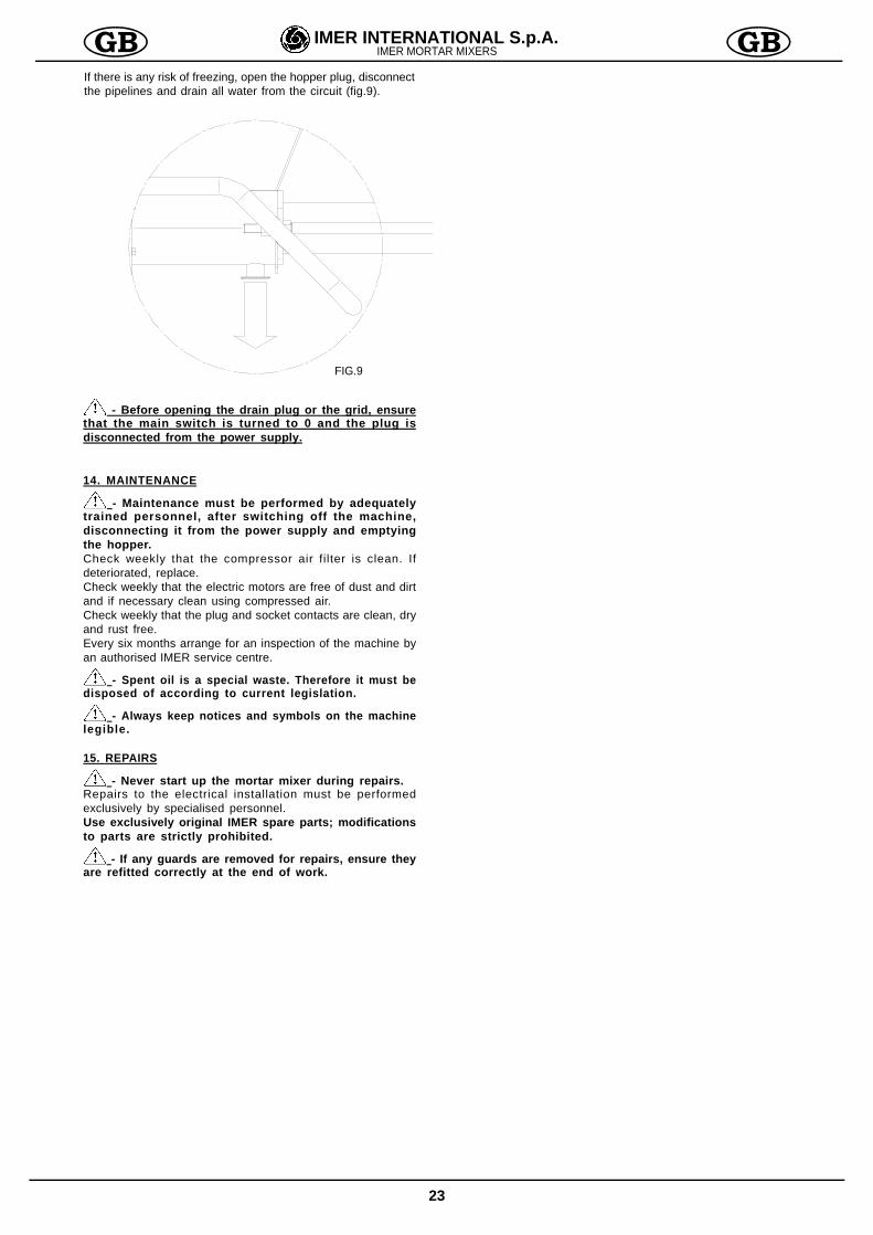
If there is any risk of freezing, open the hopper plug, disconnectthe pipelines and drain all water from the circuit (fig.9).
- Before opening the drain plug or the grid, ensurethat the main switch is turned to 0 and the plug isdisconnected from the power supply.
14. MAINTENANCE
- Maintenance must be performed by adequatelytrained personnel, after switching off the machine,disconnecting it from the power supply and emptyingthe hopper.Check weekly that the compressor air filter is clean. Ifdeteriorated, replace.Check weekly that the electric motors are free of dust and dirtand if necessary clean using compressed air.Check weekly that the plug and socket contacts are clean, dryand rust free.Every six months arrange for an inspection of the machine byan authorised IMER service centre.
- Spent oil is a special waste. Therefore it must bedisposed of according to current legislation.
- Always keep notices and symbols on the machinelegible.
15. REPAIRS
- Never start up the mortar mixer during repairs.Repairs to the electrical installation must be performedexclusively by specialised personnel.Use exclusively original IMER spare parts; modificationsto parts are strictly prohibited.
- If any guards are removed for repairs, ensure theyare refitted correctly at the end of work.
FIG.9
24
IMER INTERNATIONAL S.p.A.IMER MORTAR MIXERS
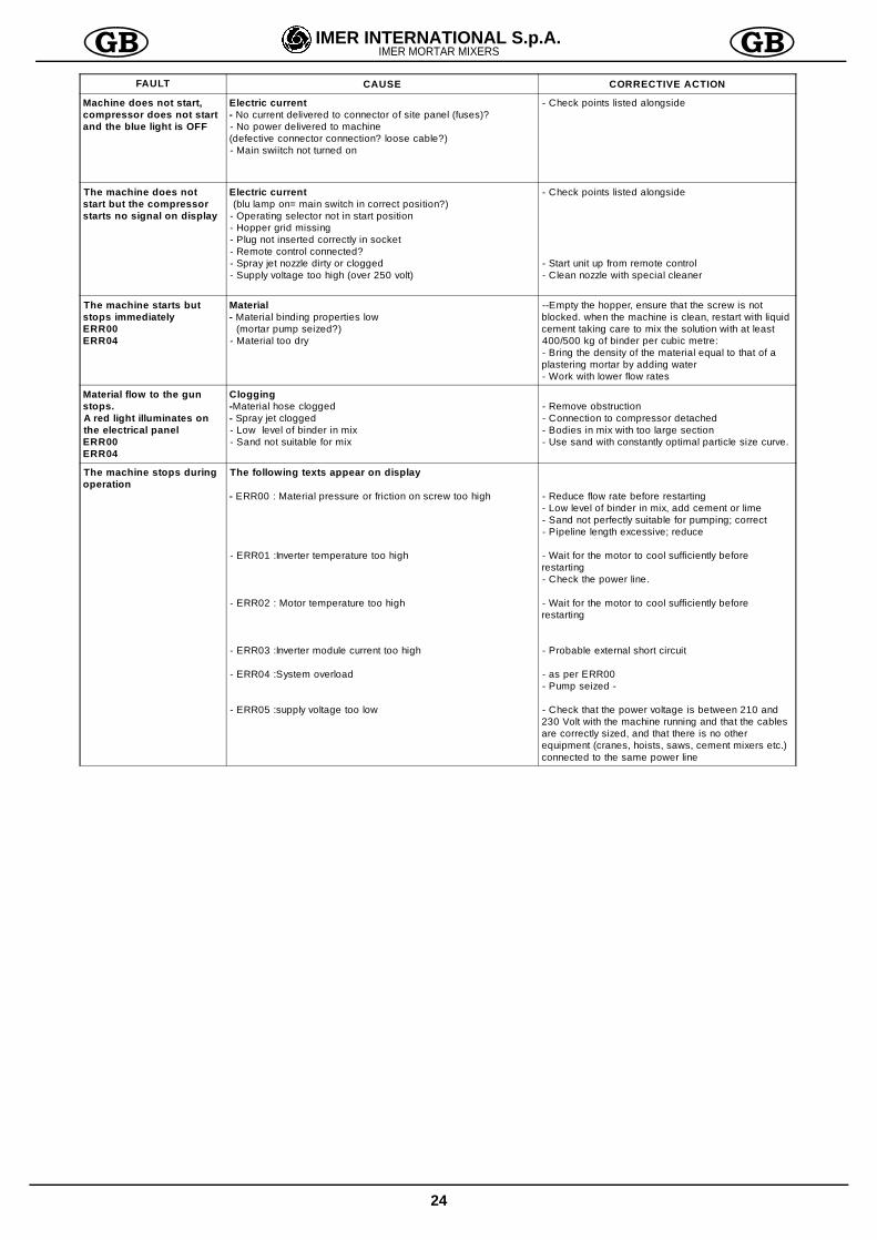
FAULT CAUSE CORRECTIVE ACTION
Machine does not start,compressor does not startand the blue light is OFF
Electric current- No current delivered to connector of site panel (fuses)?- No power delivered to machine(defective connector connection? loose cable?)- Main swiitch not turned on
- Check points listed alongside
The machine does notstart but the compressorstarts no signal on display
Electric current (blu lamp on= main switch in correct position?)
- Operating selector not in start position- Hopper grid missing- Plug not inserted correctly in socket- Remote control connected?- Spray jet nozzle dirty or clogged- Supply voltage too high (over 250 volt)
- Check points listed alongside
- Start unit up from remote control- Clean nozzle with special cleaner
The machine starts butstops immediatelyERR00ERR04
Material- Material binding properties low
(mortar pump seized?)- Material too dry
--Empty the hopper, ensure that the screw is notblocked. when the machine is clean, restart with liquidcement taking care to mix the solution with at least400/500 kg of binder per cubic metre:- Bring the density of the material equal to that of aplastering mortar by adding water- Work with lower flow rates
Material flow to the gunstops.A red light illuminates onthe electrical panelERR00ERR04
Clogging-Material hose clogged- Spray jet clogged- Low level of binder in mix- Sand not suitable for mix
- Remove obstruction- Connection to compressor detached- Bodies in mix with too large section- Use sand with constantly optimal particle size curve.
The machine stops duringoperation
The following texts appear on display
- ERR00 : Material pressure or friction on screw too high
- ERR01 :Inverter temperature too high
- ERR02 : Motor temperature too high
- ERR03 :Inverter module current too high
- ERR04 :System overload
- ERR05 :supply voltage too low
- Reduce flow rate before restarting- Low level of binder in mix, add cement or lime- Sand not perfectly suitable for pumping; correct- Pipeline length excessive; reduce
- Wait for the motor to cool sufficiently beforerestarting- Check the power line.
- Wait for the motor to cool sufficiently beforerestarting
- Probable external short circuit
- as per ERR00- Pump seized -
- Check that the power voltage is between 210 and230 Volt with the machine running and that the cablesare correctly sized, and that there is no otherequipment (cranes, hoists, saws, cement mixers etc.)connected to the same power line
39
IMER INTERNATIONAL S.p.A.INTONACATRICI IMER
24
30
11
1332
27
28
21
14
18
28
25
16
10
12
8
29
3536
7
3
15
6
2
23
33
37
34
9
1
4
5
28
11
10
12
1314
16
17
20
28
19
21
22
29
13
31
34
31
26
38
39
39
Fig.1 tav 1
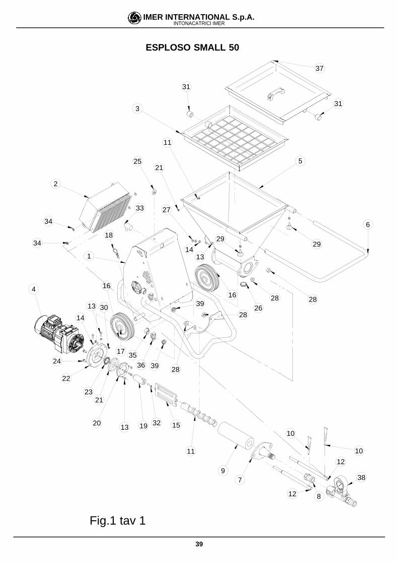
ESPLOSO SMALL 50
40
IMER INTERNATIONAL S.p.A.INTONACATRICI IMER
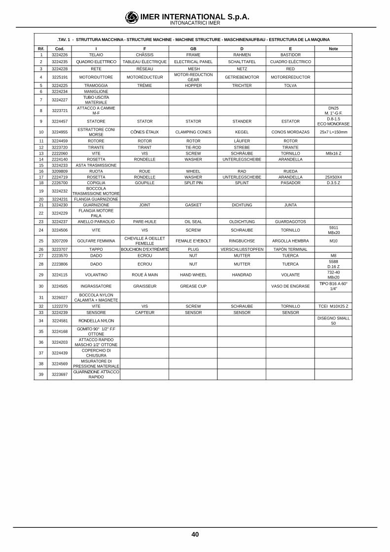
.TAV. 1 - STRUTTURA MACCHINA - STRUCTURE MACHINE - MACHINE STRUCTURE - MASCHINENAUFBAU - ESTRUCTURA DE LA MAQUINA
Rif. Cod. I F GB D E Note1 3224226 TELAIO CHÂSSIS FRAME RAHMEN BASTIDOR
2 3224235 QUADRO ELETTRICO TABLEAU ÉLECTRIQUE ELECTRICAL PANEL SCHALTTAFEL CUADRO ELÉCTRICO
3 3224228 RETE RÉSEAU MESH NETZ RED
4 3225191 MOTORIDUTTORE MOTORÉDUCTEURMOTOR-REDUCTION
GEARGETRIEBEMOTOR MOTOREREDUCTOR
5 3224225 TRAMOGGIA TRÉMIE HOPPER TRICHTER TOLVA6 3224234 MANIGLIONE
7 3224227TUBO USCITAMATERIALE
8 3223721ATTACCO A CAMME
M-FDN25
M. 1"-G F.
9 3224457 STATORE STATOR STATOR STANDER ESTATORD.8-1.5
ECO MONOFASE
10 3224955ESTRATTORE CONI
MORSECÔNES ÉTAUX CLAMPING CONES KEGEL CONOS MORDAZAS 25x7 L=150mm
11 3224459 ROTORE ROTOR ROTOR LÄUFER ROTOR
12 3223720 TIRANTE TIRANT TIE-ROD STREBE TIRANTE13 2222060 VITE VIS SCREW SCHRÄUBE TORNILLO M8x16 Z14 2224140 ROSETTA RONDELLE WASHER UNTERLEGSCHEIBE ARANDELLA15 3224233 ASTA TRASMISSIONE16 3209809 RUOTA ROUE WHEEL RAD RUEDA17 2224719 ROSETTA RONDELLE WASHER UNTERLEGSCHEIBE ARANDELLA 25X50X418 2226700 COPIGLIA GOUPILLE SPLIT PIN SPLINT PASADOR D.3.5 Z
19 3224232BOCCOLA
TRASMISSIONE MOTORE20 3224231 FLANGIA GUARNIZIONE21 3224230 GUARNIZIONE JOINT GASKET DICHTUNG JUNTA
22 3224229FLANGIA MOTORE
PALA23 3224237 ANELLO PARAOLIO PARE-HUILE OIL SEAL OLDICHTUNG GUARDAGOTOS
24 3224506 VITE VIS SCREW SCHRAUBE TORNILLO5911
M8x20
25 3207209 GOLFARE FEMMINACHEVILLE À OEILLET
FEMELLEFEMALE EYEBOLT RINGBUCHSE ARGOLLA HEMBRA M10
26 3223707 TAPPO BOUCHION D'EXTRÉMITÉ PLUG VERSCHLUßSTOPFEN TAPÒN TERMINAL
27 2223570 DADO ECROU NUT MUTTER TUERCA M8
28 2223806 DADO ECROU NUT MUTTER TUERCA5588
D.16 Z
29 3224115 VOLANTINO ROUE À MAIN HAND WHEEL HANDRAD VOLANTE732-40M8x20
30 3224505 INGRASSATORE GRAISSEUR GREASE CUP VASO DE ENGRASETIPO B16 A 60°
1/4"
31 3226027BOCCOLA NYLON
CALAMITA + MAGNETE
32 1222270 VITE VIS SCREW SCHRAUBE TORNILLO TCEI M10X25 Z
33 3224239 SENSORE CAPTEUR SENSOR SENSOR SENSOR
34 3224581 RONDELLA NYLONDISEGNO SMALL
50
35 3224168GOMITO 90° 1/2" F.F
OTTONE
36 3224203ATTACCO RAPIDO
MASCHO 1/2" OTTONE
37 3224439COPERCHIO DI
CHIUSURA
38 3224569MISURATORE DI
PRESSIONE MATERIALE
39 3223697GUARNIZIONE ATTACCO
RAPIDO
41
IMER INTERNATIONAL S.p.A.INTONACATRICI IMER
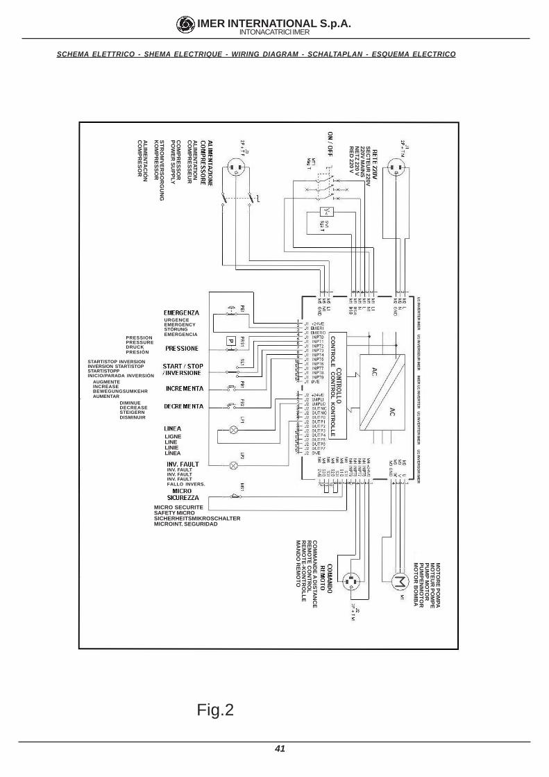
SCHEMA ELETTRICO - SHEMA ELECTRIQUE - WIRING DIAGRAM - SCHALTAPLAN - ESQUEMA ELECTRICO
Fig.2
ALIM
ENTATIO
NC
OM
PRESSEU
R
CO
MPR
ESSOR
POW
ER SU
PPLY
STRO
MVER
SOR
GU
NG
KO
MPR
ESSOR
ALIM
ENTA
CIÓ
NC
OM
PRESO
R
SECTEU
R 220V
220V MA
INS
NETZ 220 V
RED
220 V
CO
NTR
OLE C
ON
TRO
L KO
NTR
OLLE
URGENCEEMERGENCYSTÖRUNGEMERGENCIA
PRESSIONPRESSUREDRUCKPRESIÓN
START/STOP INVERSIONINVERSION START/STOPSTART/STOPPINICIO/PARADA INVERSIÓN
AUGMENTEINCREASEBEWEGUNGSUMKEHRAUMENTAR
DIMINUEDECREASESTEIGERNDISMINUIR
MICRO SECURITESAFETY MICROSICHERHEITSMIKROSCHALTERMICROINT. SEGURIDAD
LIGNELINELINIELÍNEA
CO
MM
AN
DE A D
ISTAN
CE
REM
OTE C
ON
TRO
LR
EMO
TE-KO
NTR
OLLE
MA
ND
O R
EMO
TO
INV. FAULTINV. FAULTINV. FAULTFALLO INVERS.
U1 IN
VERTER
IMER
U1 IN
VERSEU
R IM
ER IM
ER U
1 INVER
TER U
1 INVER
TER IM
ER U
1 INVER
SOR
IMER
MO
TOR
E POM
PAM
OTEU
R PO
MPE
PUM
P MO
TOR
PUM
PENM
OTO
RM
OTO
R B
OM
BA
42
IMER INTERNATIONAL S.p.A.INTONACATRICI IMER
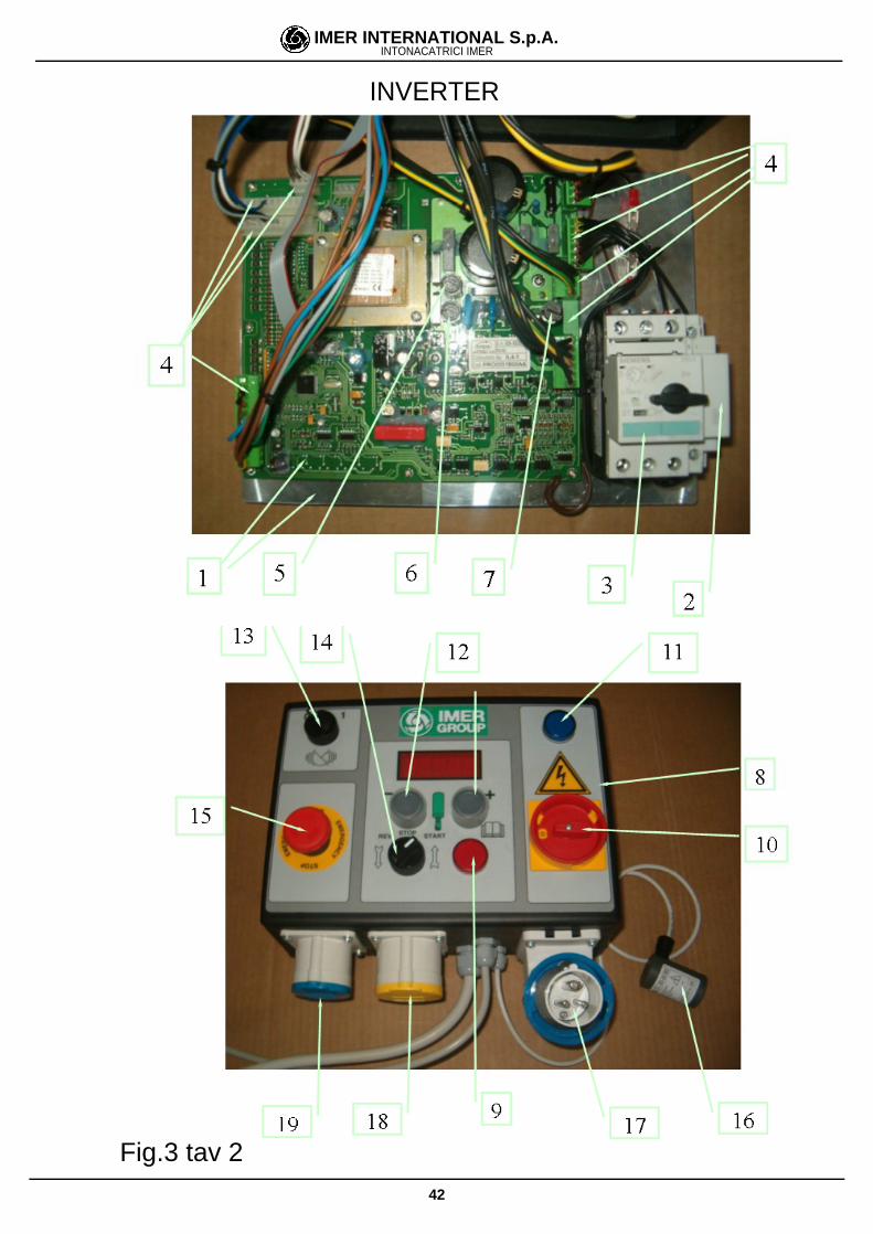
INVERTER
Fig.3 tav 2
43
IMER INTERNATIONAL S.p.A.INTONACATRICI IMER
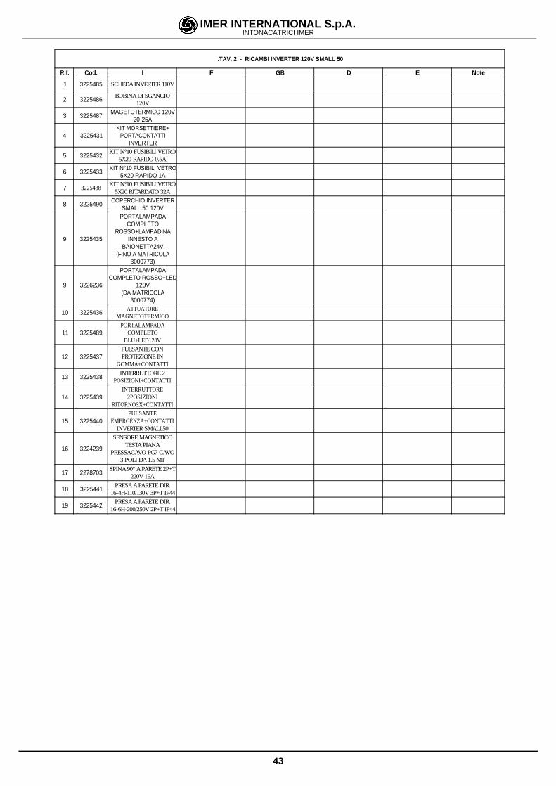
.TAV. 2 - RICAMBI INVERTER 120V SMALL 50
Rif. Cod. I F GB D E Note
1 3225485 SCHEDA INVERTER 110V
2 3225486BOBINA DI SGANCIO
120V
3 3225487MAGETOTERMICO 120V
20-25A
4 3225431KIT MORSETTIERE+
PORTACONTATTIINVERTER
5 3225432KIT N°10 FUSIBILI VETRO
5X20 RAPIDO 0.5A
6 3225433KIT N°10 FUSIBILI VETRO
5X20 RAPIDO 1A
7 3225488KIT N°10 FUSIBILI VETRO
5X20 RITARDATO 32A
8 3225490COPERCHIO INVERTER
SMALL 50 120V
9 3225435
PORTALAMPADACOMPLETO
ROSSO+LAMPADINAINNESTO A
BAIONETTA24V(FINO A MATRICOLA
3000773)
9 3226236
PORTALAMPADACOMPLETO ROSSO+LED
120V(DA MATRICOLA
3000774)
10 3225436ATTUATORE
MAGNETOTERMICO
11 3225489PORTALAMPADA
COMPLETOBLU+LED120V
12 3225437PULSANTE CONPROTEZIONE IN
GOMMA+CONTATTI
13 3225438INTERRUTTORE 2
POSIZIONI+CONTATTI
14 3225439INTERRUTTORE
2POSIZIONIRITORNOSX+CONTATTI
15 3225440PULSANTE
EMERGENZA+CONTATTIINVERTER SMALL50
16 3224239
SENSORE MAGNETICOTESTA PIANA
PRESSACAVO PG7 CAVO3 POLI DA 1.5 MT
17 2278703SPINA 90° A PARETE 2P+T
220V 16A
18 3225441PRESA A PARETE DIR.
16-4H-110/130V 3P+T IP44
19 3225442PRESA A PARETE DIR.
16-6H-200/250V 2P+T IP44
44
IMER INTERNATIONAL S.p.A.INTONACATRICI IMER
TAV3. ACCESSORI
Rif. Cod. I F GB D E Note
1 1107005KIT MALTA
PREMISCELATA/TRADIZ.FIG 1
2 1107006 KIT INIEZIONI FIG.2
3 1107009 KIT PITTURA FIG.2
4 1107010 KIT RASANTI E FUGHE FIG.2
5 1107011
LANCIA PERFUGHE,RASANTI,FUGHE
INIEZIONI CONRACCORDI
FIG.2
6 1107510 VAGLIO VIBRANTE FIG.3
7 1107511RULL0
SCHIACCIASACCHIFIG.5
8 1107512GRUPPO MISURATORE
DI PRESSIONE
9 1107513COPERCHIOTRAMOGGIA
FIG.4
10 1107543COMPRESSORE
ELETTRICO AMEMBRANA 230V/50HZ
FIG.6
11 1107516COMPRESSORE
ELETTRICO A PISTONI402m/n 230V/50HZ
12 1107518 RADIOCOMANDO
13 1107544PROLUNGA COMANDO A
DISTANZA 16MFIG 10
14 1107525
TUBO 15mPORTAMATERIALE D25
CON ATTACCHI ACAMME
FIG 8
15 1107526
TUBO 10mPORTAMATERIALE D25
CON ATTACCHI ACAMME
FIG 8
16 1107527
TUBO 5mPORTAMATERIALE D25
CON ATTACCHI ACAMME
FIG 8
17 1107529
TUBO 10mPORTAMATERIALE D19
CON ATTACCHI ACAMME
FIG 8
18 1107530TUBO 5m ARIA D13 CON
ATTACCHI GEKAFIG 7
19 1107531TUBO 10m ARIA D13
CON ATTACCHI GEKAFIG 7
20 1107532TUBO 16m ARIA D13
CON ATTACCHI GEKAFIG 7
21 1107519 KIT N10 SPUGNE D30 FIG 9
22 1107540LANCIA SPRUZZATRICE
SMALL/KOINEFIG1
FIG.4
FIG.3
FIG.5
FIG.2FIG.1
FIG.6
FIG.9
FIG.7
FIG.8 FIG.10Fig.4 tav 3
ACCESSORI
45
IMER INTERNATIONAL S.p.A.INTONACATRICI IMER
2
5
5
4
8
2
2
9
10
7
8
1
3
2
5 7
11
12
13
Fig.5 tav 4
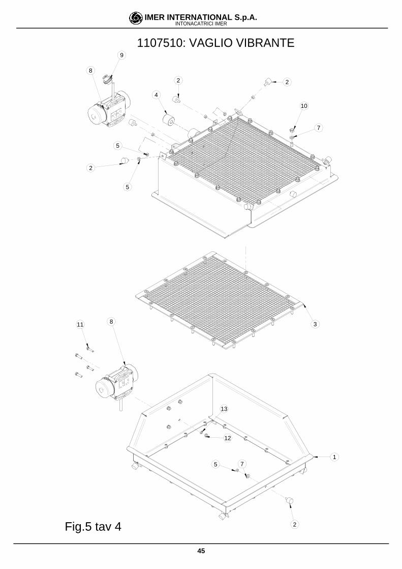
1107510: VAGLIO VIBRANTE
46
IMER INTERNATIONAL S.p.A.INTONACATRICI IMER
.TAV. 4 1107510 - VAGLIO VIBRANTE-
Rif. Cod. I F GB D E Note
1 3224526VIBROSETACCIO
VERNICIATO
2 3224801 ANTIVIBRANTEGN 17 0315
ARTEFLEX 70SHORE
3 3224563 TELAIO RETE VAGLIO
4 3226027BOCCOLA CALAMITA +
MAGNETE5 2223280 DADO 5588 D6 Z
6 3201339 VITETSPEI 8.8 5933
M8X25 Z7 1224083 ROSETTA PIANA UNI 6592 D8 Z8 3224553 MOTOVIBRATORE MICRO 230V 50HZ
9 3203504 SPINA VOLANTINO V220 IP67 16A
10 3210623DADO AUTOBLOCCANTE
D8 BASSO
11 2222010 VITE TE 8.8 5739 6 X25Z
12 2223924 DADODIN 982 M6CLASSE 8
13 2224530 RONDELLAUNI 6592 DN6DE12.5, S1.6 Z
47
IMER INTERNATIONAL S.p.A.INTONACATRICI IMER
12
3
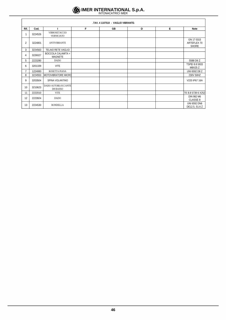
MOTORIDUTTORE 3225191
.3226244 MOTORIDUTTORE-
Rif. Cod. I F GB D E Note
1 3226244 STATORE
2 3226239 COPRIVENTOLA
3 3226240 VENTOLA
47
IMER INTERNATIONAL S.p.A.INTONACATRICI IMER
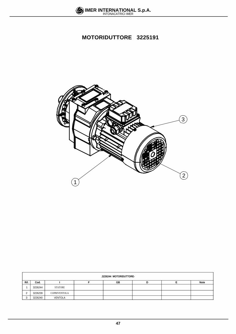
COMPRESSORE 1107543
23
25
27
1
9
3
4
511
8
1012
16
13
22
26
24
21
20
14
217
15
29
19
18
6
7
31
4
2
3
5
29
23
19
23
20
16
16
3
6
7
23
2 8
1
12
30
32
33
Fig.6 tav 5
48
IMER INTERNATIONAL S.p.A.INTONACATRICI IMER
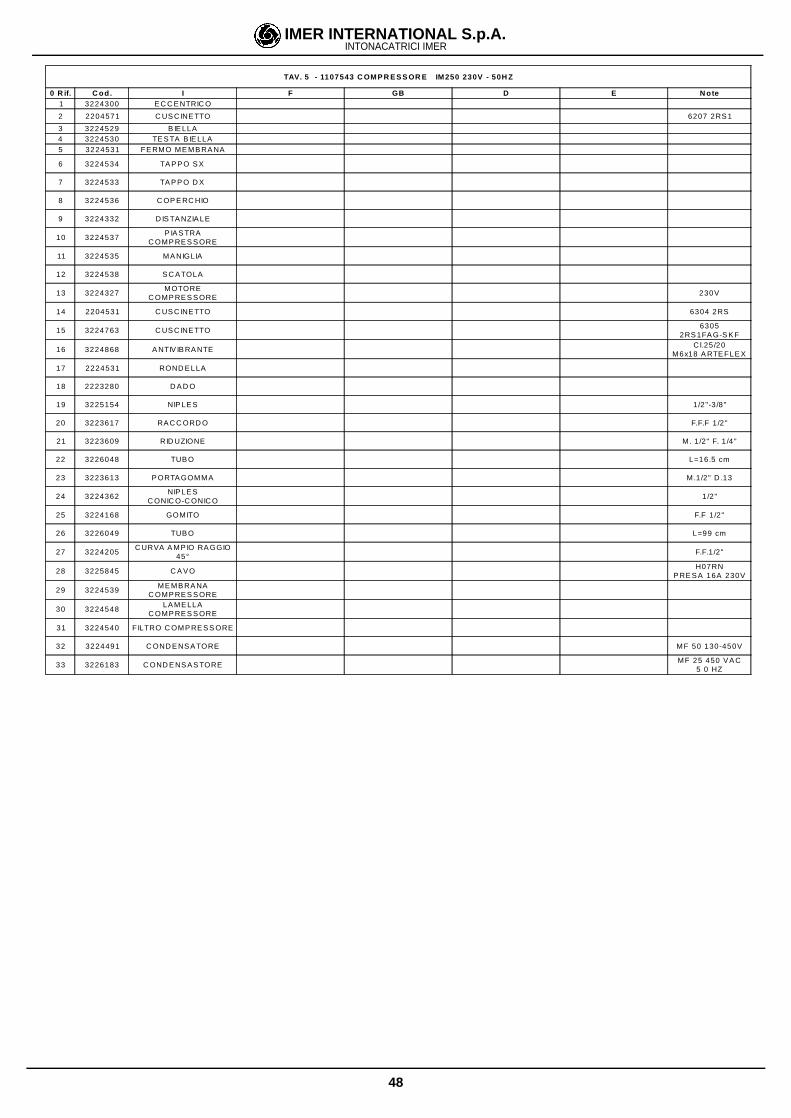
TAV. 5 - 1107543 C OMP R E S S OR E IM250 230V - 50H Z
0 R if. C od. I F GB D E N ote1 3224300 E C C E NTRIC O
2 2204571 C US C INE TTO 6207 2RS 1
3 3224529 B IE LLA4 3224530 TE S TA B IE LLA5 3224531 FE RMO ME MB RA NA
6 3224534 TA P P O S X
7 3224533 TA P P O D X
8 3224536 C OP E RC HIO
9 3224332 D IS TA NZIA LE
10 3224537P IA S TRA
C OMP RE S S ORE
11 3224535 MA NIGLIA
12 3224538 S C A TOLA
13 3224327MOTORE
C OMP RE S S ORE230V
14 2204531 C US C INE TTO 6304 2RS
15 3224763 C US C INE TTO6305
2RS 1FA G-S K F
16 3224868 A NTIV IB RA NTEC l.25 /20
M6x18 A RTE FLE X
17 2224531 ROND E LLA
18 2223280 D A D O
19 3225154 NIP LE S 1/2"-3/8"
20 3223617 RA C C ORD O F.F.F 1 /2"
21 3223609 RID UZIONE M. 1/2" F. 1 /4"
22 3226048 TUB O L=16.5 cm
23 3223613 P ORTA GOMMA M.1/2" D .13
24 3224362NIP LE S
C ONIC O-C ONIC O1/2"
25 3224168 GOMITO F.F 1/2"
26 3226049 TUB O L=99 cm
27 3224205C URVA A MP IO RA GGIO
45°F.F.1/2"
28 3225845 C A V OH07RN
P RE S A 16A 230V
29 3224539ME MB RA NA
C OMP RE S S ORE
30 3224548LA ME LLA
C OMP RE S S ORE
31 3224540 FILTRO C OMP RE S S ORE
32 3224491 C OND E NS A TORE MF 50 130-450V
33 3226183 C OND E NS A S TOREMF 25 450 V A C
5 0 HZ
49
IMER INTERNATIONAL S.p.A.INTONACATRICI IMER
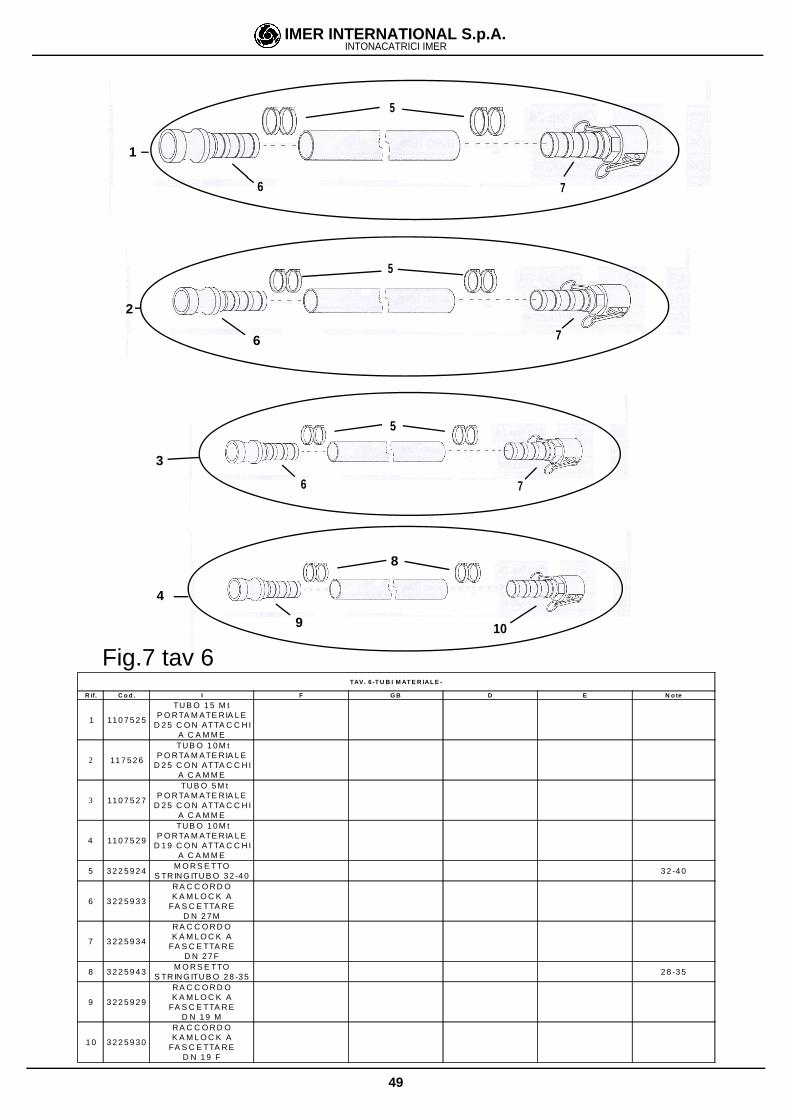
TAV. 6 -T U B I M AT E R IA L E -
R if. C o d . I F G B D E N o te
1 11 0 7 5 2 5
TU B O 1 5 M tP O RTA M ATE RIA L E
D 2 5 C O N ATTA C C H IA C A M M E
2 11 7 5 2 6
TUB O 1 0 M tP O RTA M ATE RIA L E
D 2 5 C O N ATTA C C H IA C A M M E
3 11 0 7 5 2 7
TU B O 5 M tP O RTA M ATE RIA L E
D 2 5 C O N ATTA C C H IA C A M M E
4 11 0 7 5 2 9
TUB O 1 0 M tP O RTA M ATE RIA L E
D 1 9 C O N ATTA C C H IA C A M M E
5 3 2 2 5 9 2 4M O R S E TTO
S TR IN G ITU B O 3 2 -4 03 2 -4 0
6 3 2 2 5 9 3 3
RA C C O R D OK A M L O C K A
FA S C E TTA R ED N 2 7 M
7 3 2 2 5 9 3 4
RA C C O R D OK A M L O C K A
FA S C E TTA R ED N 2 7 F
8 3 2 2 5 9 4 3M O R S E TTO
S TR IN G ITU B O 2 8 -3 52 8 -3 5
9 3 2 2 5 9 2 9
RA C C O R D OK A M L O C K A
FA S C E TTA R ED N 1 9 M
1 0 3 2 2 5 9 3 0
RA C C O R D OK A M L O C K A
FA S C E TTA R ED N 1 9 F
Fig.7 tav 6
5
1
5
6 7
4
3
2
5
8
6 7
6 7
9 10
50
IMER INTERNATIONAL S.p.A.INTONACATRICI IMER
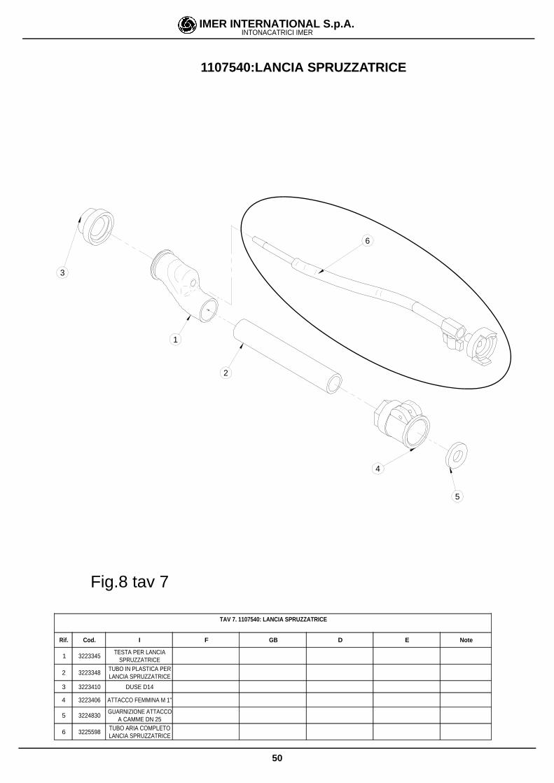
TAV 7. 1107540: LANCIA SPRUZZATRICE
Rif. Cod. I F GB D E Note
1 3223345TESTA PER LANCIA
SPRUZZATRICE
2 3223348TUBO IN PLASTICA PERLANCIA SPRUZZATRICE
3 3223410 DUSE D14
4 3223406 ATTACCO FEMMINA M 1"
5 3224830GUARNIZIONE ATTACCO
A CAMME DN 25
6 3225598TUBO ARIA COMPLETOLANCIA SPRUZZATRICE
1
2
4
3
5
6
1107540:LANCIA SPRUZZATRICE
Fig.8 tav 7
51
IMER INTERNATIONAL S.p.A.INTONACATRICI IMER
4
9
3
5
7
6
11
2
1
8
10
11
8
12
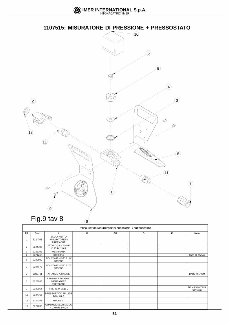
.TAV 8:1107515:MISURATORE DI PRESSIONE + PRESSOSTATO
Rif. Cod. I F GB D E Note
1 3224762BLOCCHETTO
MISURATORE DIPRESSIONE
2 3224709ATTACCO A CAMME
D.25 F-1" G F3 3223392 MEMBRANA4 2224460 ROSETTA 6539 D. 15X45
5 3223609RIDUZIONE M.1/2" F.1/4"
OTTONE
6 3224173RIDUZIONE M.1/2" F.1/2"
OTTONE
7 3223721 ATTACCO A CAMME DN25 M-1" GM
8 3224765LAMIERA APPOGGIO
MISURATOREPRESSIONE
9 2222064 VITE TE M 8X16 ZTE M 8X16 Z UNI
5739 8.8
10 3224766PRESSOSTATO FF 142-8
DAH 1/4 G
11 3224353 NIPLES 1"
12 3224830GUARNIZIONE ATTACCO
A CAMME DN 25
1107515: MISURATORE DI PRESSIONE + PRESSOSTATO
Fig.9 tav 8
52
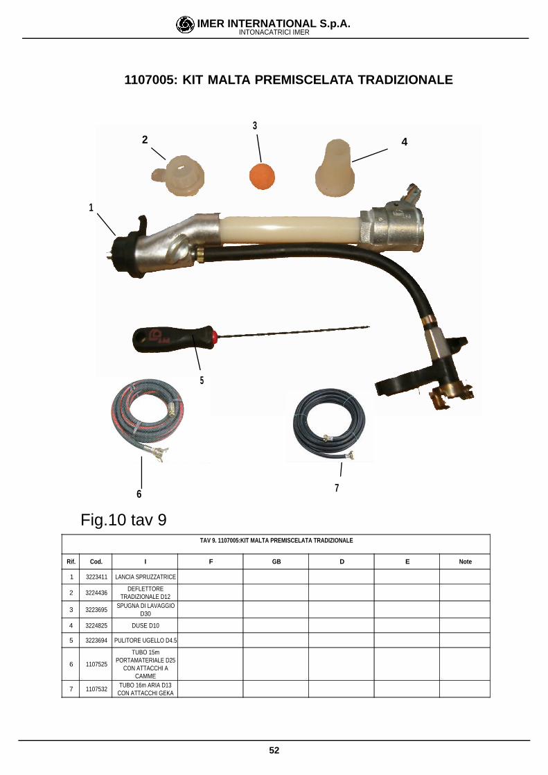
IMER INTERNATIONAL S.p.A.INTONACATRICI IMER
TAV 9. 1107005:KIT MALTA PREMISCELATA TRADIZIONALE
Rif. Cod. I F GB D E Note
1 3223411 LANCIA SPRUZZATRICE
2 3224436DEFLETTORE
TRADIZIONALE D12
3 3223695SPUGNA DI LAVAGGIO
D30
4 3224825 DUSE D10
5 3223694 PULITORE UGELLO D4.5
6 1107525
TUBO 15mPORTAMATERIALE D25
CON ATTACCHI ACAMME
7 1107532TUBO 16m ARIA D13
CON ATTACCHI GEKA
1
5
3 2 4
6 7
1107005: KIT MALTA PREMISCELATA TRADIZIONALE
Fig.10 tav 9

53
IMER INTERNATIONAL S.p.A.INTONACATRICI IMER
TAV10. 1107010KIT RASANTI E FUGHE
Rif. Cod. I F GB D E Note
1 3224301LANCIA SPRUZZATRICEPER RASANTI FUGHE E
INIEZIONI
2 3224956 NIPLES 1" OTTONE
3 3224701ATTACCO A CAMMEDN25 F1"G F PLAST.
BETON.
4 3224704DEFLETTORE CONPORTAGOMMA D16
SMALL 50
5 3224957RIDUZIONE M.3/4" F.1/2"V
OTTONE
6 3223613PORTAGOMMA M.1/2"X13 OTTONE
7 1220019 TAPPO FILETTATO M.3/8"
8 1220018 TAPPO FILETTATO M.1/4"
9 3223695SPUGNA DI LAVAGGIO
D30
10 3224303DEFLETTORE SMALL 50
D5
11 3224302DEFLETTORE SMALL 50
D6
12 3224279DEFLETTORE SMALL 50
D8
13 3224413DEFLETORE SMALL 50
D10
14 3223694 PULITORE UGELLO D4.5
15 1107525
TUBO 15mPORTAMATERIALE D25
CON ATTACCHI ACAMME
16 1107532TUBO 16m ARIA D13
CON ATTACCHI GEKA
1107010:KIT RASANTI E FUGHE
4
7
1
5
6 8
9
10 12 11
13
14
15 16
2
3
Fig.11 tav. 10
54
IMER INTERNATIONAL S.p.A.INTONACATRICI IMER
TAV 11. 1107009: KIT PITTURA
Rif. Cod. I F GB D E Note
1 3224301LANCIA SPRUZZATRICEPER RASANTI FUGHE E
INIEZIONI
2 3224707NIPLES RID. 1"M. 3/4"M.
OTTONE CIL.
3 3224706ATTACCO A CAMMEDN19 F-3/4" G F ALL
300302
4 3224658SPUGNA DI LAVAGGIO
D25
5 3224303DEFLETTORE SMALL 50
D5
6 3224302DEFLETTORE SMALL 50
D6
7 3224709ATTACCO ACAMME
DN25 F 1"G FBETONCINO
8 3223608RIDUZIONE M.1" F. 3/4"
OTTONE
9 3224328ATTACCO ACAMME
DN19 M.3/4" G M INOX
10 3223694 PULITORE UGELLO D 4.5
11 1107529
TUBO 1OmPORTAMATERIALE D19
CON ATTACCHI ACAMME
12 1107532TUBO 16m ARIA D13
CON ATTACCHI GEKA
4
5
1
7
3
2
10
6
8
9
11 12
1107010:KIT PITTURA
Fig.12 tav 11
55
IMER INTERNATIONAL S.p.A.INTONACATRICI IMER
5
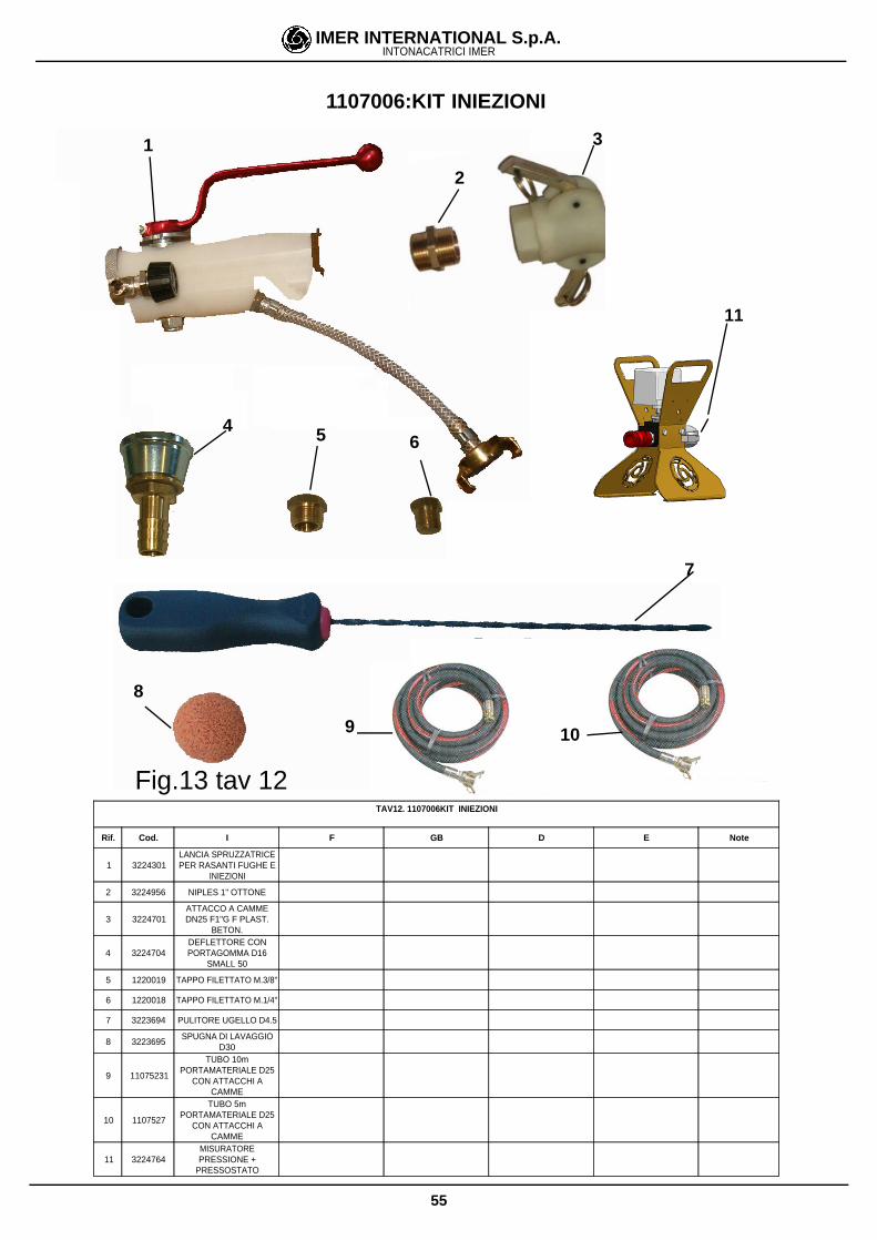
TAV12. 1107006KIT INIEZIONI
Rif. Cod. I F GB D E Note
1 3224301LANCIA SPRUZZATRICEPER RASANTI FUGHE E
INIEZIONI
2 3224956 NIPLES 1" OTTONE
3 3224701ATTACCO A CAMMEDN25 F1"G F PLAST.
BETON.
4 3224704DEFLETTORE CONPORTAGOMMA D16
SMALL 50
5 1220019 TAPPO FILETTATO M.3/8"
6 1220018 TAPPO FILETTATO M.1/4"
7 3223694 PULITORE UGELLO D4.5
8 3223695SPUGNA DI LAVAGGIO
D30
9 11075231
TUBO 10mPORTAMATERIALE D25
CON ATTACCHI ACAMME
10 1107527
TUBO 5mPORTAMATERIALE D25
CON ATTACCHI ACAMME
11 3224764MISURATOREPRESSIONE +
PRESSOSTATO
1107006:KIT INIEZIONI
3
6
2
4
1
8
7
9 10
11
Fig.13 tav 12
56
IMER INTERNATIONAL S.p.A.INTONACATRICI IMER
11
5
3
4
6
8
9
7
10
2
1
10
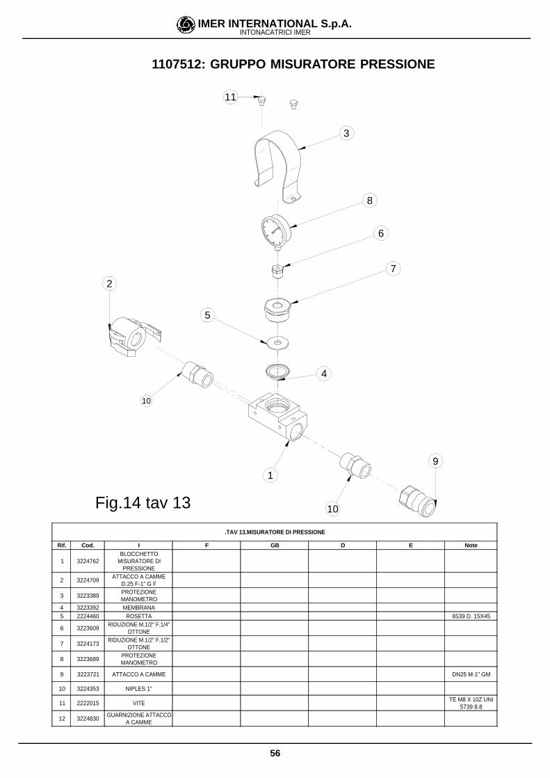
.TAV 13.MISURATORE DI PRESSIONE
Rif. Cod. I F GB D E Note
1 3224762BLOCCHETTO
MISURATORE DIPRESSIONE
2 3224709ATTACCO A CAMME
D.25 F-1" G F
3 3223389PROTEZIONEMANOMETRO
4 3223392 MEMBRANA5 2224460 ROSETTA 6539 D. 15X45
6 3223609RIDUZIONE M.1/2" F.1/4"
OTTONE
7 3224173RIDUZIONE M.1/2" F.1/2"
OTTONE
8 3223689PROTEZIONEMANOMETRO
9 3223721 ATTACCO A CAMME DN25 M-1" GM
10 3224353 NIPLES 1"
11 2222015 VITETE M8 X 10Z UNI
5739 8.8
12 3224830GUARNIZIONE ATTACCO
A CAMME
1107512: GRUPPO MISURATORE PRESSIONE
Fig.14 tav 13
57
IMER INTERNATIONAL S.p.A.INTONACATRICI IMER
18
14
1215
3
6
10
9
2
11
8
4
19
7
17
1
5
16
13
1107511: RULLO SCHIACCIASACCHI
Fig.15 tav 14
58
IMER INTERNATIONAL S.p.A.INTONACATRICI IMER
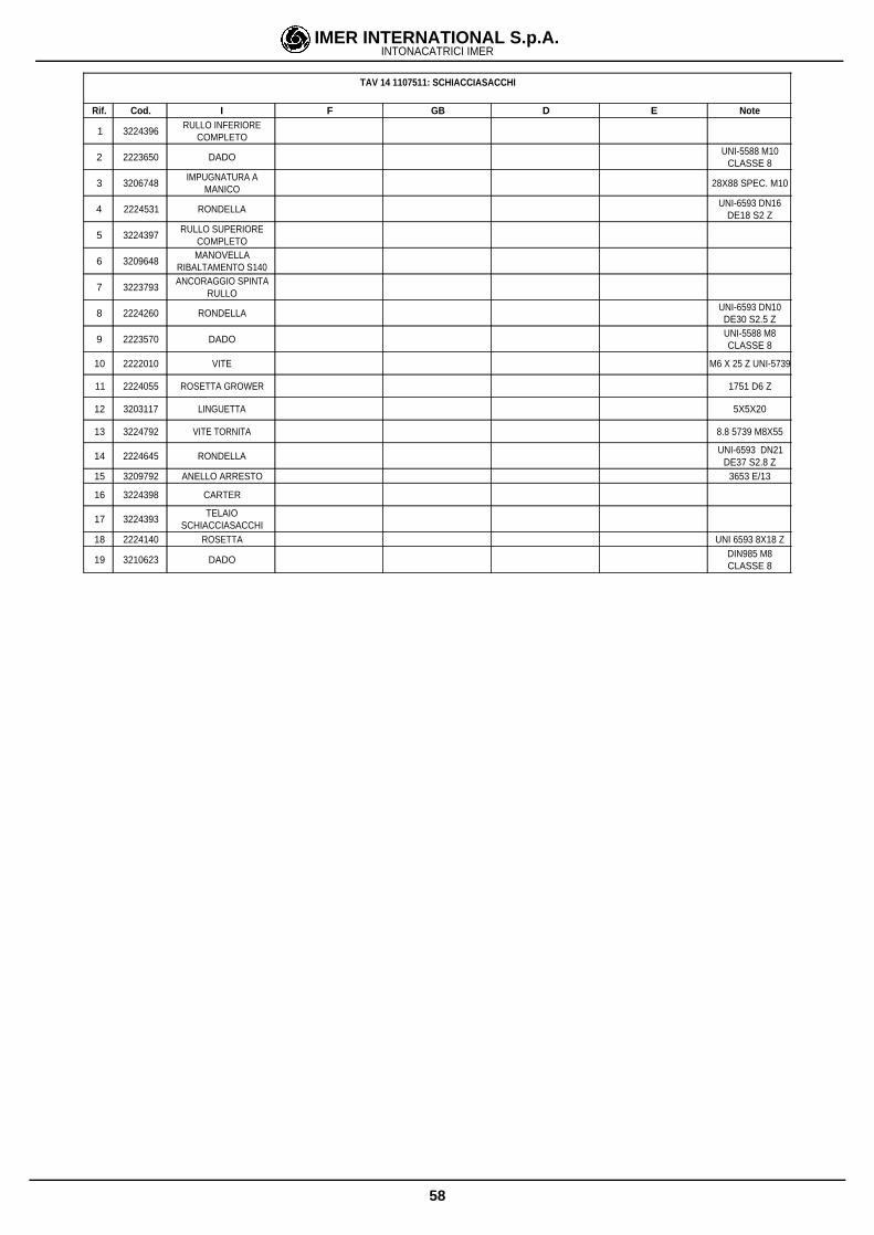
TAV 14 1107511: SCHIACCIASACCHI
Rif. Cod. I F GB D E Note
1 3224396RULLO INFERIORE
COMPLETO
2 2223650 DADOUNI-5588 M10
CLASSE 8
3 3206748IMPUGNATURA A
MANICO28X88 SPEC. M10
4 2224531 RONDELLAUNI-6593 DN16
DE18 S2 Z
5 3224397RULLO SUPERIORE
COMPLETO
6 3209648MANOVELLA
RIBALTAMENTO S140
7 3223793ANCORAGGIO SPINTA
RULLO
8 2224260 RONDELLAUNI-6593 DN10DE30 S2.5 Z
9 2223570 DADOUNI-5588 M8CLASSE 8
10 2222010 VITE M6 X 25 Z UNI-5739
11 2224055 ROSETTA GROWER 1751 D6 Z
12 3203117 LINGUETTA 5X5X20
13 3224792 VITE TORNITA 8.8 5739 M8X55
14 2224645 RONDELLAUNI-6593 DN21
DE37 S2.8 Z15 3209792 ANELLO ARRESTO 3653 E/13
16 3224398 CARTER
17 3224393TELAIO
SCHIACCIASACCHI18 2224140 ROSETTA UNI 6593 8X18 Z
19 3210623 DADODIN985 M8CLASSE 8
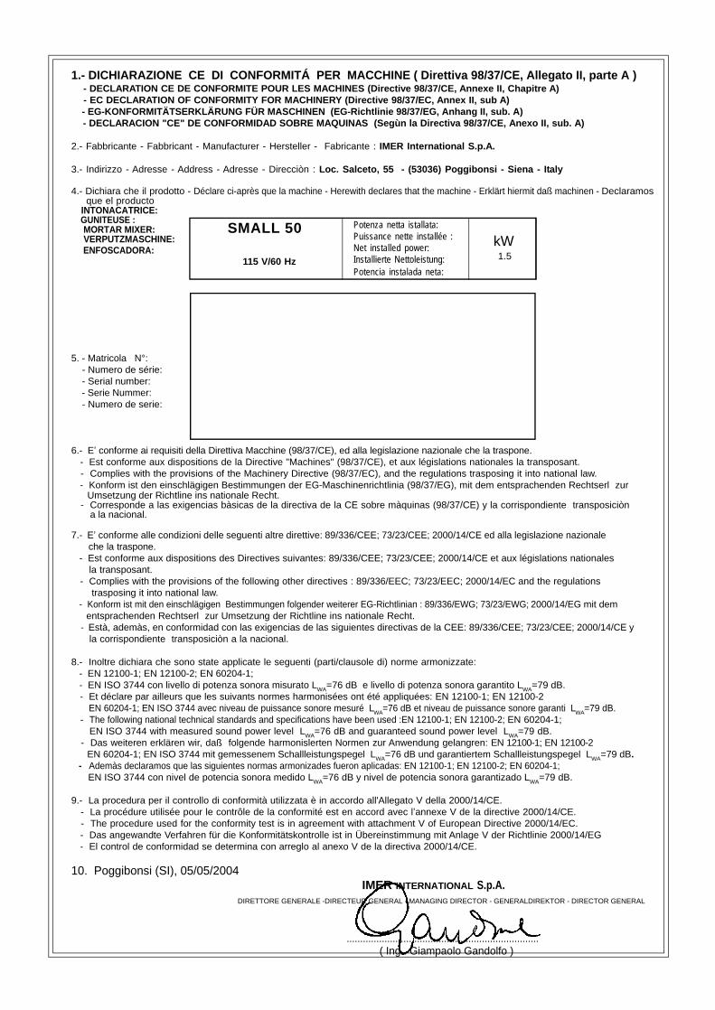
1.- DICHIARAZIONE CE DI CONFORMITÁ PER MACCHINE ( Direttiva 98/37/CE, Allegato II, parte A ) - DECLARATION CE DE CONFORMITE POUR LES MACHINES (Directive 98/37/CE, Annexe II, Chapitre A) - EC DECLARATION OF CONFORMITY FOR MACHINERY (Directive 98/37/EC, Annex II, sub A)
- EG-KONFORMITÄTSERKLÄRUNG FÜR MASCHINEN (EG-Richtlinie 98/37/EG, Anhang II, sub. A) - DECLARACION "CE" DE CONFORMIDAD SOBRE MAQUINAS (Segùn la Directiva 98/37/CE, Anexo II, sub. A)
2.- Fabbricante - Fabbricant - Manufacturer - Hersteller - Fabricante : IMER International S.p.A.
3.- Indirizzo - Adresse - Address - Adresse - Direcciòn : Loc. Salceto, 55 - (53036) Poggibonsi - Siena - Italy
4.- Dichiara che il prodotto - Déclare ci-après que la machine - Herewith declares that the machine - Erklärt hiermit daß machinen - Declaramos que el producto
INTONACATRICE: GUNITEUSE : MORTAR MIXER: VERPUTZMASCHINE: ENFOSCADORA:
5. - Matricola N°: - Numero de série: - Serial number: - Serie Nummer: - Numero de serie:
6.- E conforme ai requisiti della Direttiva Macchine (98/37/CE), ed alla legislazione nazionale che la traspone. - Est conforme aux dispositions de la Directive "Machines" (98/37/CE), et aux législations nationales la transposant. - Complies with the provisions of the Machinery Directive (98/37/EC), and the regulations trasposing it into national law. - Konform ist den einschlägigen Bestimmungen der EG-Maschinenrichtlinia (98/37/EG), mit dem entsprachenden Rechtserl zur
Umsetzung der Richtline ins nationale Recht. - Corresponde a las exigencias bàsicas de la directiva de la CE sobre màquinas (98/37/CE) y la corrispondiente transposiciòn
a la nacional.
7.- E conforme alle condizioni delle seguenti altre direttive: 89/336/CEE; 73/23/CEE; 2000/14/CE ed alla legislazione nazionale che la traspone.
- Est conforme aux dispositions des Directives suivantes: 89/336/CEE; 73/23/CEE; 2000/14/CE et aux législations nationales la transposant.
- Complies with the provisions of the following other directives : 89/336/EEC; 73/23/EEC; 2000/14/EC and the regulations trasposing it into national law.
- Konform ist mit den einschlägigen Bestimmungen folgender weiterer EG-Richtlinian : 89/336/EWG; 73/23/EWG; 2000/14/EG mit dem entsprachenden Rechtserl zur Umsetzung der Richtline ins nationale Recht.
- Està, ademàs, en conformidad con las exigencias de las siguientes directivas de la CEE: 89/336/CEE; 73/23/CEE; 2000/14/CE y la corrispondiente transposiciòn a la nacional.
8.- Inoltre dichiara che sono state applicate le seguenti (parti/clausole di) norme armonizzate: - EN 12100-1; EN 12100-2; EN 60204-1; - EN ISO 3744 con livello di potenza sonora misurato LWA=76 dB e livello di potenza sonora garantito LWA=79 dB.
- Et déclare par ailleurs que les suivants normes harmonisées ont été appliquées: EN 12100-1; EN 12100-2 EN 60204-1; EN ISO 3744 avec niveau de puissance sonore mesuré LWA=76 dB et niveau de puissance sonore garanti LWA=79 dB.
- The following national technical standards and specifications have been used :EN 12100-1; EN 12100-2; EN 60204-1; EN ISO 3744 with measured sound power level LWA=76 dB and guaranteed sound power level LWA=79 dB.
- Das weiteren erklären wir, daß folgende harmonislerten Normen zur Anwendung gelangren: EN 12100-1; EN 12100-2 EN 60204-1; EN ISO 3744 mit gemessenem Schallleistungspegel LWA=76 dB und garantiertem Schallleistungspegel LWA=79 dB. - Ademàs declaramos que las siguientes normas armonizades fueron aplicadas: EN 12100-1; EN 12100-2; EN 60204-1;
EN ISO 3744 con nivel de potencia sonora medido LWA=76 dB y nivel de potencia sonora garantizado LWA=79 dB.
9.- La procedura per il controllo di conformità utilizzata è in accordo all'Allegato V della 2000/14/CE. - La procédure utilisée pour le contrôle de la conformité est en accord avec l annexe V de la directive 2000/14/CE. - The procedure used for the conformity test is in agreement with attachment V of European Directive 2000/14/EC. - Das angewandte Verfahren für die Konformitätskontrolle ist in Übereinstimmung mit Anlage V der Richtlinie 2000/14/EG - El control de conformidad se determina con arreglo al anexo V de la directiva 2000/14/CE.
10. Poggibonsi (SI), 05/05/2004 IMER INTERNATIONAL S.p.A.
DIRETTORE GENERALE -DIRECTEUR GENERAL - MANAGING DIRECTOR - GENERALDIREKTOR - DIRECTOR GENERAL
....................................................................... ( Ing. Giampaolo Gandolfo )
Potenza netta istallata:Puissance nette installée :Net installed power:Installierte Nettoleistung:Potencia instalada neta:
kW 1.5115 V/60 Hz
SMALL 50
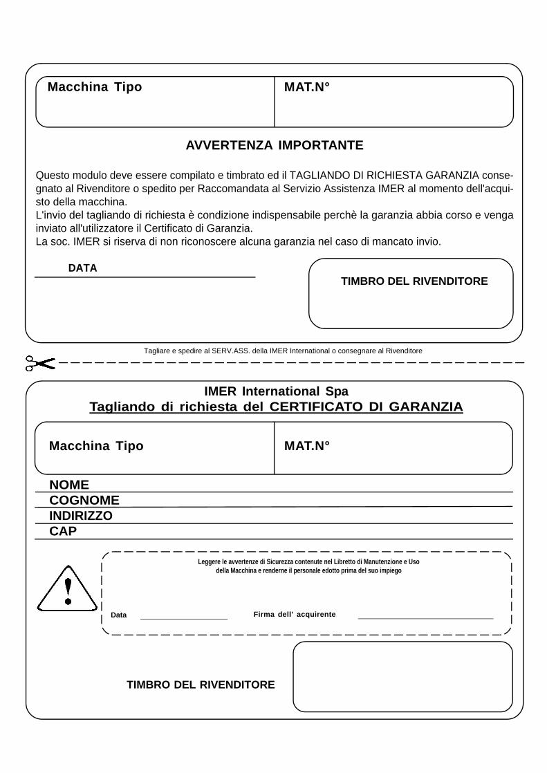
Macchina Tipo MAT.N°
NOMECOGNOMEINDIRIZZOCAP
TIMBRO DEL RIVENDITORE
Tagliare e spedire al SERV.ASS. della IMER International o consegnare al Rivenditore
Macchina Tipo MAT.N°
IMER International SpaTagliando di richiesta del CERTIFICATO DI GARANZIA
Leggere le avvertenze di Sicurezza contenute nel Libretto di Manutenzione e Usodella Macchina e renderne il personale edotto prima del suo impiego
Data Firma dell' acquirente
AVVERTENZA IMPORTANTE
Questo modulo deve essere compilato e timbrato ed il TAGLIANDO DI RICHIESTA GARANZIA conse-gnato al Rivenditore o spedito per Raccomandata al Servizio Assistenza IMER al momento dell'acqui-sto della macchina.L'invio del tagliando di richiesta è condizione indispensabile perchè la garanzia abbia corso e vengainviato all'utilizzatore il Certificato di Garanzia.La soc. IMER si riserva di non riconoscere alcuna garanzia nel caso di mancato invio.
DATA TIMBRO DEL RIVENDITORE
Spett.le Ditta
IMER International S.p.a.Loc.Salceto
53036 POGGIBONSI (SI) - ITALY
IMER International S.p.A. garantisce all acquirente l acquisto di una macchina nuova, integra in ogni suo componente e che i materiali IMERsono controllati esenti da vizi o difetti di fabbricazione.
CONDIZIONI DI GARANZIA
Per la validità della garanzia occorre che venga restituito all'azienda opportunamente compilato, il relativo modulo allegato al manuale di uso emanutenzione. Per garanzia si intende la riparazione e/o sostituzione di quelle parti che risultassero difettose di fabbricazione. E' esclusa lasostituzione integrale.Per tutti i beni prodotti, la garanzia delle parti che risultassero difettose di fabbricazione, è di dodici mesi dalla data di spedizione o consegnaall'utilizzatore. La garanzia sul motore endotermico è assicurata dal relativo fabbricante.
I materiali ritenuti difettosi dovranno essere fatti pervenire presso il ns. stabilimento, franco destino, e dopo benestare tecnico sarà riconosciutoe inviato il materiale in porto assegnato. Restando in ogni caso a carico esclusivo dell'acquirente tutte le spese di mano d'opera e trasferterelative alla riparazione o sostituzione eventualmente eseguite presso l'acquirente in base alle tariffe pubblicate dall'ANIMA.
L applicazione della garanzia è subordinata al rigoroso rispetto delle istruzioni indicate nel manuale di uso e manutenzione ed alla esecuzionepuntuale degli interventi di manutenzione previsti eseguiti da personale di assistenza autorizzato IMER. La garanzia non copre i danni causatida condizioni ambientali particolari non previste (ad es. ambienti corrosivi, scariche atmosferiche, calore, immersione) o calamità naturali.Il fabbricante non sarà responsabile per gli eventuali danni a terzi consequenziali all uso della macchina od attribuibili indirettamente ad essa,né sarà imputabile per danni da perdita di profitto imputabile a sosta forzata, qualunque ne sia la causa.La garanzia viene a cessare quando:1) I prodotti venduti vengono modificati, riparati, smontati o comunque manomessi dall'acquirente o vengono sugli stessi montate attrezzatu
re o altri accessori, non espressamente forniti o autorizzati dalla venditrice o sui quali siano stati utilizzati ricambi non originali.2) I prodotti venduti non vengono usati o montati in modo conforme alle indicazioni della venditrice, o per negligenza od errori da parte
dell utilizzatore.3) Vengono impiegati combustibili e lubrificanti inadatti, in caso di ostruzione di prese d aria o scarichi o di problemi causati da bulloneria
evidentemente allentatasi nell uso e lasciata tale.4) Le riparazioni effettuate in garanzia non interrompono il periodo della garanzia stessa.5) I collegamenti elettrici non sono effettuati secondo le ns.disposizioni causando danno ai componenti elettrici.
Il rivenditore, all atto della consegna, è incaricato di trasmettere all acquirente finale il manuale fornito con la macchina, contenente le necessarieistruzioni, affinché la macchina venga usata solamente dopo che l operatore le abbia ricevute e lette.


![PERSPECTIVAS PARA O USO DA PESQUISA OBSERVACIONAL EM …eprints.rclis.org/31890/1/8647275-28456-4-PB.pdf · 2017-10-23 · Campinas, SP v.15 n.3 p.550-570 set./dez. 2017 [551] RESUMO:](https://img.pdfslide.tips/doc/110x75/5ec4e1e93866dc5418480567/perspectivas-para-o-uso-da-pesquisa-observacional-em-2017-10-23-campinas-sp-v15.jpg)