Embed Size (px)
Citation preview
CES5801 Design and Construction in Timber
Project #8P Ferguson, Robert
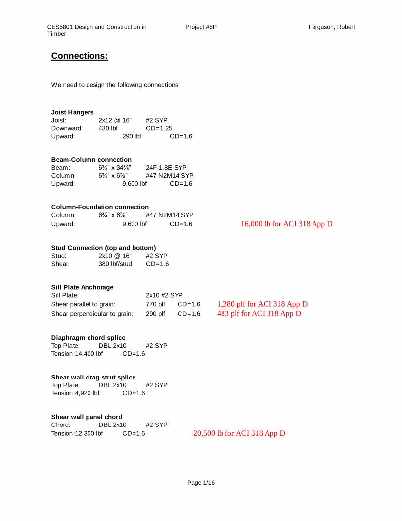
Connections:
We need to design the following connections:
Joist HangersJoist: 2x12 @ 16” #2 SYPDownward: 430 lbf CD=1.25Upward: 290 lbf CD=1.6
Beam-Column connectionBeam: 6¾” x 34⅞” 24F-1.8E SYPColumn: 6¾” x 6⅞” #47 N2M14 SYPUpward: 9,600 lbf CD=1.6
Column-Foundation connectionColumn: 6¾” x 6⅞” #47 N2M14 SYPUpward: 9,600 lbf CD=1.6 16,000 lb for ACI 318 App D
Stud Connection (top and bottom)Stud: 2x10 @ 16” #2 SYPShear: 380 lbf/stud CD=1.6
Sill Plate AnchorageSill Plate: 2x10 #2 SYPShear parallel to grain: 770 plf CD=1.6 1,280 plf for ACI 318 App DShear perpendicular to grain: 290 plf CD=1.6 483 plf for ACI 318 App D
Diaphragm chord spliceTop Plate: DBL 2x10 #2 SYPTension:14,400 lbf CD=1.6
Shear wall drag strut spliceTop Plate: DBL 2x10 #2 SYPTension:4,920 lbf CD=1.6
Shear wall panel chordChord: DBL 2x10 #2 SYPTension:12,300 lbf CD=1.6 20,500 lb for ACI 318 App D
Page 1/16
CES5801 Design and Construction in Timber
Project #8P Ferguson, Robert
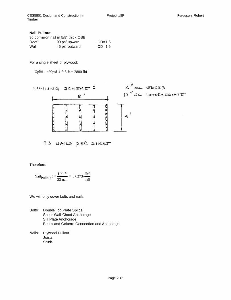
Nail Pullout8d common nail in 5/8” thick OSBRoof: 90 psf upward CD=1.6Wall: 45 psf outward CD=1.6
For a single sheet of plywood:
Uplift 90psf 4 ft 8 ft 2880 lbf=:=
Therefore:
NailPulloutUplift33 nail
87.273lbfnail=:=
We will only cover bolts and nails:
Bolts: Double Top Plate SpliceShear Wall Chord AnchorageSill Plate AnchorageBeam and Column Connection and Anchorage
Nails: Plywood PulloutJoistsStuds
Page 2/16
CES5801 Design and Construction in Timber
Project #8P Ferguson, Robert
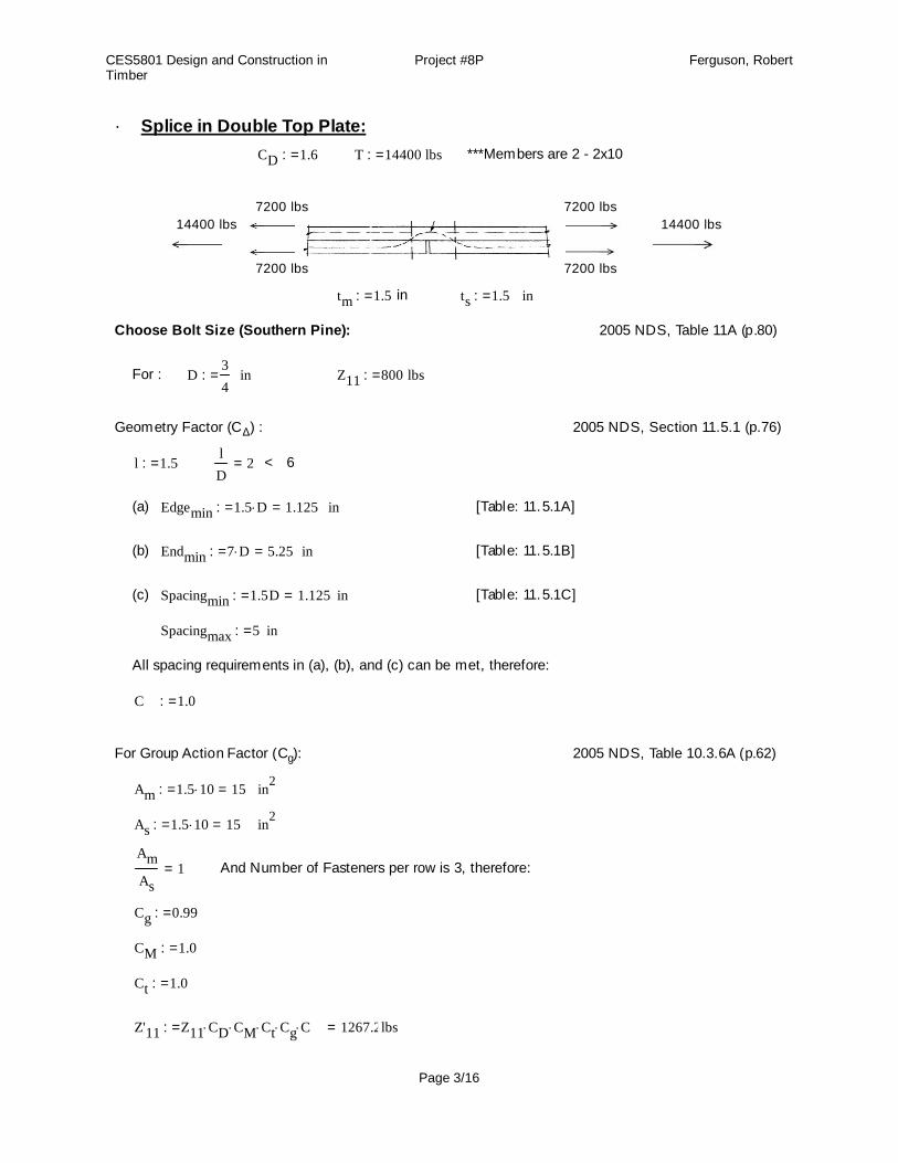
Splice in Double Top Plate:·
CD 1.6:= T 14400:= lbs ***Members are 2 - 2x10
7200 lbs 7200 lbs14400 lbs 14400 lbs
7200 lbs 7200 lbs
tm 1.5:= in ts 1.5:= in
Choose Bolt Size (Southern Pine): 2005 NDS, Table 11A (p.80)
For : D34
:= in Z11 800:= lbs
Geometry Factor (CΔ) : 2005 NDS, Section 11.5.1 (p.76)
l 1.5:=lD
2= < 6
(a) Edgemin 1.5 D 1.125=:= in [Table: 11.5.1A]
(b) Endmin 7 D 5.25=:= in [Table: 11.5.1B]
(c) Spacingmin 1.5D 1.125=:= in [Table: 11.5.1C]
Spacingmax 5:= in
All spacing requirements in (a), (b), and (c) can be met, therefore:
CΔ 1.0:=
For Group Action Factor (Cg): 2005 NDS, Table 10.3.6A (p.62)
Am 1.5 10 15=:= in2
As 1.5 10 15=:= in2
AmAs
1= And Number of Fasteners per row is 3, therefore:
Cg 0.99:=
CM 1.0:=
Ct 1.0:=
Z'11 Z11 CD CM Ct Cg CΔ 1267.2=:= lbs
Page 3/16
CES5801 Design and Construction in Timber
Project #8P Ferguson, Robert
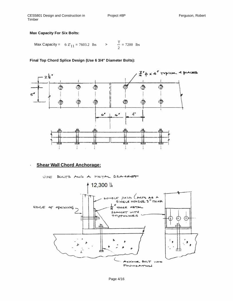
Max Capacity For Six Bolts:
Max Capacity = 6 Z'11 7603.2= lbs > T2
7200= lbs
Final Top Chord Splice Design (Use 6 3/4" Diameter Bolts):
Shear Wall Chord Anchorage:·
Page 4/16
CES5801 Design and Construction in Timber
Project #8P Ferguson, Robert
For Double Studs And Metal Bracket:
T 12300:= lbs (studs are 2 - 2x10 in)
Choose Bolt Size (Southern Pine): 2005 NDS, Table 11B (p.82)
Interpolate b/t 2.5" and 3" main member thickness:
For : D 1:= in Z112480 1830-
21830+ 2155=:= lbs
nT
CD Z11( )3.567=:= Try 4 - 1" bolts, 2 rows of 2.
Geometry Factor (CΔ) : 2005 NDS, Section 11.5.1 (p.76)
l 3:=lD
3= < 6
(a) Edgemin 1.5 D 1.5=:= in [Table :11.5.1A]
(b) Endmin 7 D 7=:= in [Table :11.5.1B]
(c) Spacingmin 1.5D 1.5=:= in [Table :11.5.1C]
Spacingmax 5:= in
All spacing requirements in (a), (b), and (c) can be met.
CΔ 1.0:=
For Group Action Factor (Cg): 2005 NDS, Table 10.3.6C (p.63)
Am 1.5 10 15=:= in2
As .25 8 2=:= in2
AmAs
7.5= And Number of Fasteners per row is 2, therefore:
Cg 0.99:=
CM 1.0:=
Ct 1.0:=
Z'11 Z11 CD CM Ct Cg CΔ 3413.52=:= lbs
Max Capacity For Four Bolts:
Max Capacity = 4 Z'11 13654.08= lbs > T 12300= lbs
Page 5/16
CES5801 Design and Construction in Timber
Project #8P Ferguson, Robert
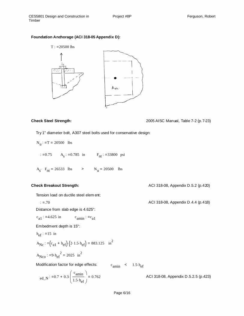
Foundation Anchorage (ACI 318-05 Appendix D):
T 20500:= lbs
Check Steel Strength: 2005 AISC Manual, Table 7-2 (p.7-23)
Try 1" diameter bolt, A307 steel bolts used for conservative design:
Nu T 20500=:= lbs
ϕ 0.75:= As 0.785:= in ϕFnt 33800:= psi
As ϕFnt 26533= lbs > Nu 20500= lbs
Check Breakout Strength: ACI 318-08, Appendix D .5.2 (p.420)
Tension load on ductile steel elem ent:
ϕ .70:= ACI 318-08, Appendix D .4.4 (p.418)
Distance from slab edge is 4.625":
ca1 4.625:= in camin ca1:=
Embedment depth is 15":
hef 15:= in
ANc ca1 hef+( ) 2 1.5 hef( ) 883.125=:= in2
ANco 9 hef2
2025=:= in2
Modification factor for edge effects: camin < 1.5 hef
Ψed_N 0.7 0.3camin1.5 hef
+ 0.762=:= ACI 318-08, Appendix D .5.2.5 (p.423)
Page 6/16

CES5801 Design and Construction in Timber
Project #8P Ferguson, Robert
Modification factor for cracked concrete at service loads:
Ψc_N 1.0:= ACI 318-08, Appendix D .5.2.6 (p.424)
Modification factor for post-installed anchors:
Ψcp_N 1.0:= For cast in place anchor. ACI 318-08, Appendix D .5.2.7 (p.425)
Basic concrete breakout strength of a single anchor in cracked concrete:
kc 24:= (for bolts) f'c 4000:=
Nb kc f'c hef1.5
88181.631=:= lbs
NcbANcANco
Ψed_N Ψc_N Ψcp_N Nb 29291.407=:= lbs
ϕ Ncb 20503.985= lbs > Nu 20500= lbs
Check Pullout Strength: ACI 318-08, Appendix D .5.3 (p.426)
ϕ .70:= Ψc_P 1.0:= (for cracking) Abrgπ 1.6252
4π 12
4- 1.289=:=
Np 8 Abrg f'c 41233.404=:=
ϕ Np 28863.383= lb
Check Side-Face Blowout Strength:
2.5ca1 < hef , therefore no blowout calculation is not needed
Final Shear Wall C hord Anchorage Design:
Page 7/16
CES5801 Design and Construction in Timber
Project #8P Ferguson, Robert
Bottom Sill Plate Anchorage :·
Shear parallel to grain: F11 770:= plf CD 1.6:=
Shear perpendicular to grain: Fper 290:= plf CD 1.6:=
Sill Plate Size: 2 x 10 On Concrete ts 1.5:= in
Choose Bolt Size:
Try 1" bolt so that the same bolt is used everywhere:
D 1:= in
Check Shear Perpendicular To Grain: 2005 NDS, Table 11E (p.85)
Zper 2250:= lbs / bolt
CΔ 1.0:=
Cg 1.0:=
CM 1.0:=
Ct 1.0:=
Z'per Zper CD CM Ct Cg CΔ 3600=:=lbsbolt
Check Shear Parallel To Grain: 2005 NDS, Table 11E (p.85)
Z11 1020:=lbsbolt
CΔ 1.0:=
Cg 1.0:=
CM 1.0:=
Ct 1.0:=
Z'11 Z11 CD CM Ct Cg CΔ 1632=:=lbsbolt
Design Edge Distance:
Edgemin 4 D 4=:= in < 4.625 in
Design Lateral Spacing:
SpacingperZ'perFper
12.414=:= ft Therefore, use 12' o.c.
Page 8/16
CES5801 Design and Construction in Timber
Project #8P Ferguson, Robert
Spacing11Z'11F11
2.119=:= ft
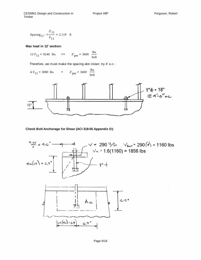
Max load in 12' section:
12 F11 9240= lbs >> Z'per 3600=lbsbolt
Therefore, we must make the spacing alot closer; try 4' o.c.:
4 F11 3080= lbs < Z'per 3600=lbsbolt
Check Bolt Anchorage for Shear (ACI 318-05 Appendix D):
Page 9/16
CES5801 Design and Construction in Timber
Project #8P Ferguson, Robert
Check Steel Strength: 2005 AISC Manual, Table 7-1 (p.7-22)
Try 1" diameter bolt, A307 steel bolts used for conservative design:
Vu 1856:= lbs
ϕ 0.75:= As 0.785:= in ϕFnv 18000:= psi
As ϕFnv 14130= lbs > Vu 1856= lbs
Check Breakout Strength: ACI 318-08, Appendix D .6.2 (p.429)
Tension load on ductile steel elem ent:
ϕ .70:= ACI 318-08, Appendix D .4.4 (p.418)
Distance from slab edge is 4.625":
ca1 4.625:= in
Embedment depth is 11":
hef 11:= in
AVc 1.5 ca1 1.5 ca1+( )1.5 ca1 96.258=:= in2
AVco 4.5 ca12
96.258=:= in2
Modification factor for edge effects:
Ψed_V 1.0:= Only one edge. ACI 318-08, Appendix D .6.2.6 (p.433)
Modification factor for cracked concrete at service loads:
Ψc_V 1.0:= ACI 318-08, Appendix D .6.2.7 (p.434)
Basic concrete breakout strength in shear of a single anchor in cracked concrete:
da 1:= in 8 da 8=
le 8 da:= f'c 4000:=
Vb 7leda
0.2
da f'c ca11.5
6674.422=:= lbs ACI 318-08, Appendix D .6.2.2 (p.431)
VcbAVcAVco
Ψed_V Ψc_V Vb 6674.422=:= lbs
ϕ Vcb 4672.095= lbs > Vu 1856= lbs
Page 10/16
CES5801 Design and Construction in Timber
Project #8P Ferguson, Robert
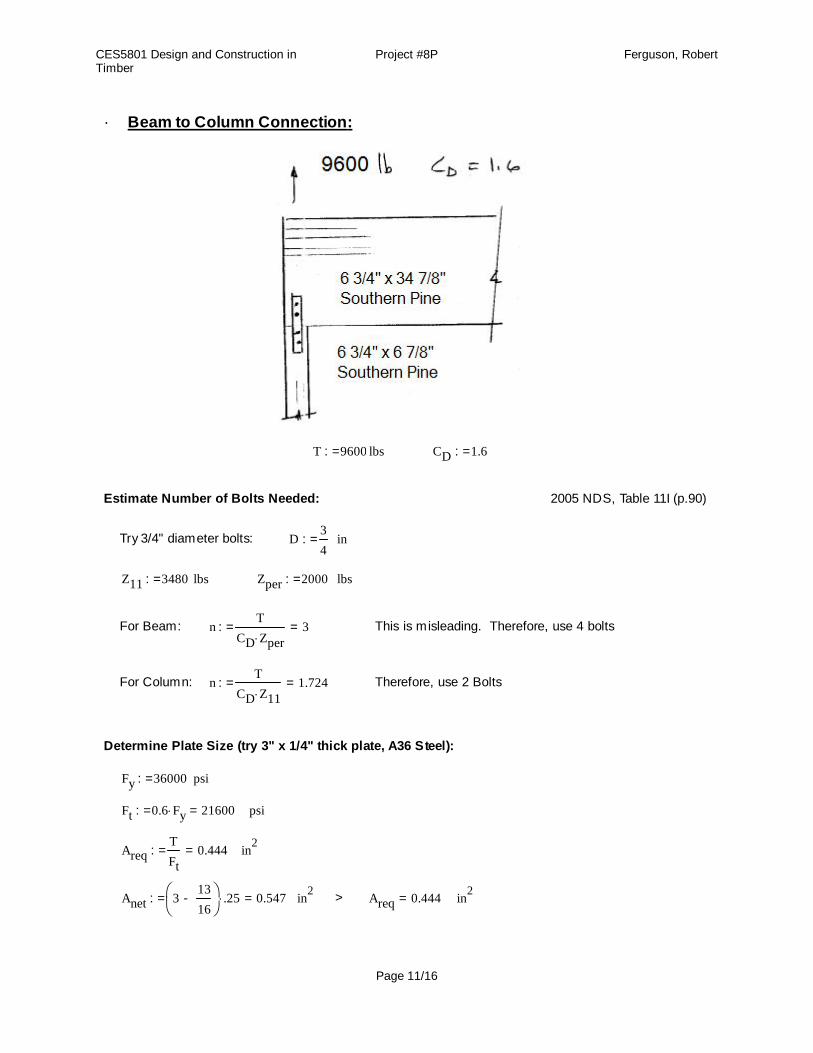
Beam to Column Connection :·
T 9600:= lbs CD 1.6:=
Estimate Number of Bolts Needed: 2005 NDS, Table 11I (p.90)
Try 3/4" diameter bolts: D34
:= in
Z11 3480:= lbs Zper 2000:= lbs
For Beam: nT
CD Zper3=:= This is misleading. Therefore, use 4 bolts
For Column: nT
CD Z111.724=:= Therefore, use 2 Bolts
Determine Plate Size (try 3" x 1/4" thick plate, A36 Steel):
Fy 36000:= psi
Ft 0.6 Fy 21600=:= psi
AreqTFt
0.444=:= in2
Anet 31316
-
.25 0.547=:= in2 > Areq 0.444= in2
Page 11/16
CES5801 Design and Construction in Timber
Project #8P Ferguson, Robert
For Group Action Factor, Cg: 2005 NDS, Table 10.3.6C (p.63)
Am 6.75 6.875 46.406=:= in2
As 2 .25 3 1.5=:= in2
AmAs
30.938=
For 2 bolts: For 4 bolts:
Cg2 1.0:= Cg4 0.96:=
Geometry Factor (CΔ) : 2005 NDS, Section 11.5.1 (p.76)
(a) Edgemin 1.5 D 1.125=:= in [Table :11.5.1A]
(b) Endmin 7 D 5.25=:= in [Table :11.5.1B]
(c) Spacingmin 4 D 3=:= in [Table :11.5.1C]
Spacingmax 5:= in
All spacing requirements in (a), (b), and (c) can be met, therefore:
CΔ 1.0:=
CM 1.0:=
Ct 1.0:=
Capacity For Column:
Z'column Z11 CD CM Ct Cg2 CΔ 5568=:= lbs
For 2 Bolts:
2 Z'column 11136= lbs > T 9600= lbs
Capacity For Beam:
Z'beam Zper CD CM Ct Cg4 CΔ 3072=:= lbs
For 4 Bolts:
4 Z'beam 12288= lbs > T 9600= lbs
Page 12/16
CES5801 Design and Construction in Timber
Project #8P Ferguson, Robert
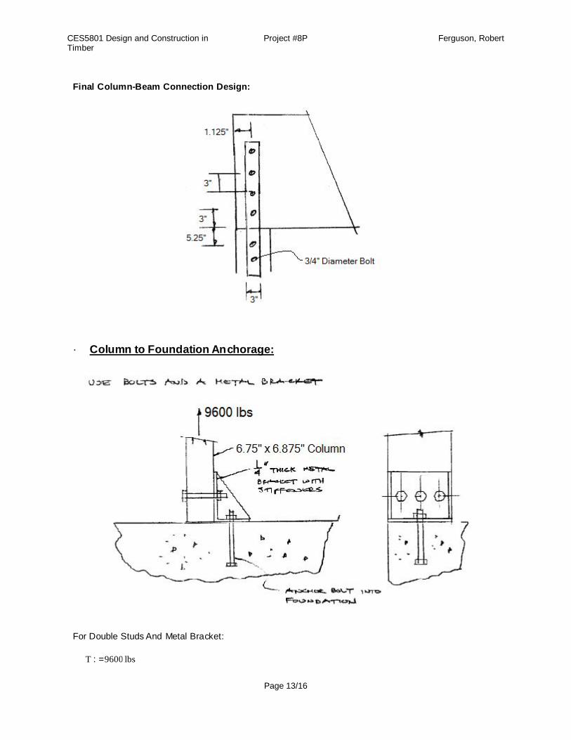
Final Column-Beam Connection Design:
Column to Foundation Anchorage:·
For Double Studs And Metal Bracket:
T 9600:= lbs
Page 13/16
CES5801 Design and Construction in Timber
Project #8P Ferguson, Robert
Choose Bolt Size (Southern Pine): 2005 NDS, Table 11B (p.82)
Main member size is 6.875", therefore interpolate b/t 7.5" and 5.5":
For : D 1:= in Z11 2980:= lbs
nT
CD Z11( )2.013=:= Try 2 - 1" bolts, I know we should round up, but I'm using my
engineering judgement to say it's close enough.
Geometry Factor (CΔ) : 2005 NDS, Section 11.5.1 (p.76)
l 6.875:=lD
6.875= < 6
(a) Edgemin 1.5 D 1.5=:= in [Table :11.5.1A]
(b) Endmin 7 D 7=:= in [Table :11.5.1B]
(c) Spacingmin 1.5D 1.5=:= in [Table :11.5.1C]
Spacingmax 5:= in
All spacing requirements in (a), (b), and (c) can be met.
CΔ 1.0:=
For Group Action Factor (Cg): 2005 NDS, Table 10.3.6C (p.63)
Am 1.5 10 15=:= in2
As .25 8 2=:= in2
AmAs
7.5= And Number of Fasteners per row is 2, therefore:
Cg 0.99:=
CM 1.0:=
Ct 1.0:=
Z'11 Z11 CD CM Ct Cg CΔ 4720.32=:= lbs
Max Capacity For Four Bolts:
Max Capacity = 4 Z'11 18881.28= lbs > T 9600= lbs
Page 14/16
CES5801 Design and Construction in Timber
Project #8P Ferguson, Robert
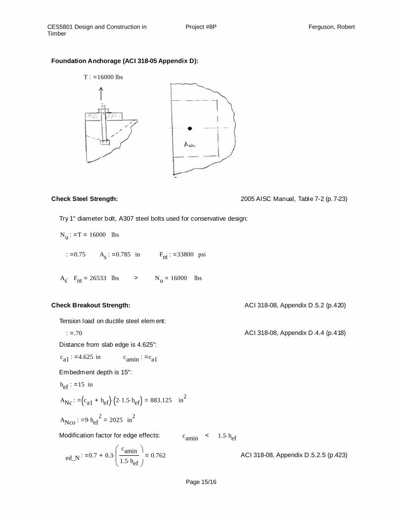
Foundation Anchorage (ACI 318-05 Appendix D):
T 16000:= lbs
Check Steel Strength: 2005 AISC Manual, Table 7-2 (p.7-23)
Try 1" diameter bolt, A307 steel bolts used for conservative design:
Nu T 16000=:= lbs
ϕ 0.75:= As 0.785:= in ϕFnt 33800:= psi
As ϕFnt 26533= lbs > Nu 16000= lbs
Check Breakout Strength: ACI 318-08, Appendix D .5.2 (p.420)
Tension load on ductile steel elem ent:
ϕ .70:= ACI 318-08, Appendix D .4.4 (p.418)
Distance from slab edge is 4.625":
ca1 4.625:= in camin ca1:=
Embedment depth is 15":
hef 15:= in
ANc ca1 hef+( ) 2 1.5 hef( ) 883.125=:= in2
ANco 9 hef2
2025=:= in2
Modification factor for edge effects: camin < 1.5 hef
Ψed_N 0.7 0.3camin1.5 hef
+ 0.762=:= ACI 318-08, Appendix D .5.2.5 (p.423)
Page 15/16
CES5801 Design and Construction in Timber
Project #8P Ferguson, Robert
Modification factor for cracked concrete at service loads:
Ψc_N 1.0:= ACI 318-08, Appendix D .5.2.6 (p.424)
Modification factor for post-installed anchors:
Ψcp_N 1.0:= For cast in place anchor. ACI 318-08, Appendix D .5.2.7 (p.425)
Basic concrete breakout strength of a single anchor in cracked concrete:
kc 24:= (for bolts) f'c 4000:=
Nb kc f'c hef1.5
88181.631=:= lbs
NcbANcANco
Ψed_N Ψc_N Ψcp_N Nb 29291.407=:= lbs
ϕ Ncb 20503.985= lbs > Nu 16000= lbs
Check Pullout Strength: ACI 318-08, Appendix D .5.3 (p.426)
ϕ .70:= Ψc_P 1.0:= (for cracking) Abrgπ 1.6252
4π 12
4- 1.289=:=
Np 8 Abrg f'c 41233.404=:=
ϕ Np 28863.383= lb
Check Side-Face Blowout Strength:
2.5ca1 < hef , therefore no blowout calculation is not needed
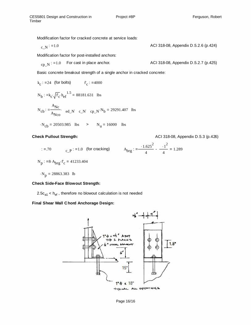
Final Shear Wall C hord Anchorage Design:
Page 16/16