Embed Size (px)
Citation preview

MAX7219 8 digit 7‐segment LED Display module
Specifications:
1. MAX7219 Common cathode LED driving IC
2. Support 2x 4 digit common cathode LED Module, size 0.56inch
3. PCB are designed to support perfect cascading of multiple MAX7219
4. LED module Color Choice: White, Red, Orange, Blue, Bright green
5. Size: 100mmx19mm
Package List:
1. 2x 0.56” 4 digit 7‐segment 5461 common cathode module
2. PCB,
3. MAX7219 DIP24 and DIP24 IC socket
4. 2x 10uF capacitor (1206), 1x 4.7k resistor (1206)
5. 1x5 pin 2.54 header
Soldering guide:
1. Solder 10uF capacitor to C1, C2.
4.7k resistor (High brightness) to R1
(any orientation is OK)
2. Solder IC socket and 1x5pin header
3. Solder the LED module (Caution: Aware the location pin1 of the LED module
before soldering)
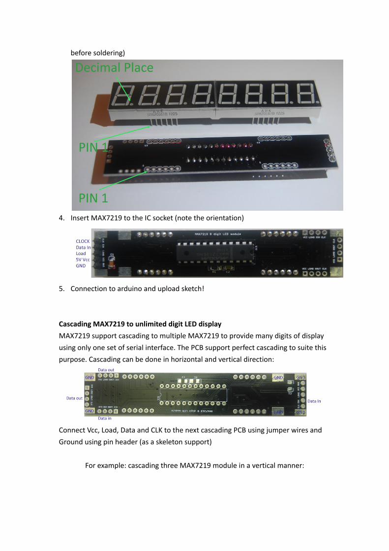
4. Insert MAX7219 to the IC socket (note the orientation)
5. Connection to arduino and upload sketch!
Cascading MAX7219 to unlimited digit LED display
MAX7219 support cascading to multiple MAX7219 to provide many digits of display
using only one set of serial interface. The PCB support perfect cascading to suite this
purpose. Cascading can be done in horizontal and vertical direction:
Connect Vcc, Load, Data and CLK to the next cascading PCB using jumper wires and
Ground using pin header (as a skeleton support)
For example: cascading three MAX7219 module in a vertical manner:
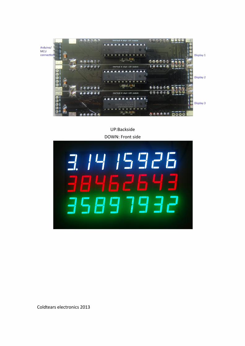
UP:Backside
DOWN: Front side
Coldtears electronics 2013