Embed Size (px)
Citation preview
AIR-CONDITIONER
1/52
ISTRUZIONI DI MONTAGGIO DEL CONDIZIONATOREAIR CONDITIONER MOUNTING INSTRUCTIONS
INSTRUCTIONS POUR LE MONTAGE DU CLIMATISEURMONTAGE DER KLIMAANLAGE
INSTRUCCIONES DE MONTAJE DEL ACONDICIONADOR
CONDIZIONATOREAIR-CONDITIONER
CLIMATISEURKLIMAANLAGE
ACONDICIONADOR
MB Actros MP2-MP3
AIR-CONDITIONER
2/52
SOMMARIO PAGINA
Immagini esplosi 3
Avvertenze generali 5
Componenti forniti 6
Installazione / Fasi di montaggio 7
SOMMAIRE PAGE
Éclatés 3
Recommandations générales 23
Composants fournis 24
Installation / Phases de montage 25
SUMARIO PÁGINA
Imágenes desglosadas 3
Advertencias generales 41
Componentes suministrados 42
Instalación / Fases de montaje 43
CONTENTS PAGE
Exploded views 3
General precautions 14
Supplied components 15
Installation/Assembly steps 16
INHALT SEITE
Explosionszeichnungen 3
Allgemeine Hinweise 32
Mitgelieferte Komponenten 33
Aufstellung / Montagephasen 34
AIR-CONDITIONER
3/52
01
AIR-CONDITIONER
4/52
02
CONDIZIONATORE
ITALIANO
5/52
AVVERTENZE GENERALI
Per l'installazione, è importante attenersi scrupolosamente alle indicazioni riportate nel presente manuale. Il costruttore declina ogni responsabilità, in caso di danni a cose e persone provocati da installazioni o varia-zioni non conformi dell'impianto.
Gli interventi di installazione devono essere effettuati esclusivamente da un tecnico specializzato ed informato sui pericoli connessi e sulle relative prescrizioni.
Utilizzare il condizionatore esclusivamente per l’uso previsto dal produttore e non eseguire modifiche o trasformazioni dell’apparecchio in modo arbitrario.
Non inserire le mani nella griglia delle bocchette di aerazione e non introdurre nessun oggetto esterno nell’impianto.
PRIMA DELL’INSTALLAZIONE DELL’IMPIANTO, SCOLLEGARE TUTTI I COLLEGAMENTI ALLA BATTERIA DEL VEICOLO.
Installare il gruppo a tetto in modo sicuro per impedire che possa rovesciarsi o cadere.
Durante le fasi di montaggio e l’esecuzione di fori sul veicolo, prestare attenzione a non danneggiare cablaggi o tubazioni di impianti già installati in precedenza.
Quando si effettuano delle operazioni in prossimità delle batterie (evaporatrice e/o condensatrice) prestare attenzione a non tagliarsi con i bordi delle alette.
Se i cavi elettrici devono passare attraverso pareti con spigoli vivi, utilizzare tubi di protezione o canaline specifiche.
Fissare fermamente i cavi elettrici prestando particolare attenzione al loro percorso lungo pareti metalliche che con-ducono elettricità; evitare inoltre il contatto con parti taglienti.
Prima di iniziare l'installazione, controllare che una volta posizionato il gruppo sul tetto, le aperture per l'ingresso ed uscita aria sul condensatore non siano ostruite o coperte.
Verificare se in seguito al montaggio del condizionatore, è necessario modificare la registrazione dell’altezza del veicolo segnalata sul libretto di circolazione (contattare la casa produttrice dell’automezzo).
Spegnere il condizionatore prima di utilizzare dispositivi di lavaggio automatico per la pulizia del veicolo.
Verificare che la batteria del veicolo abbia una capacità di almeno 170Ah.
Per il montaggio su consiglia l’utilizzo di sigillante poliuretanico adatto a giunti in lamiera, cofani, tettucci e superfici verniciate.
Prima di posizionare il condizionatore sul tetto del veicolo, verificare che su di esso si possa accedere e che possa sostenere il peso del condizionatore che si intende installare.
CONDIZIONATORE
ITALIANO
6/52
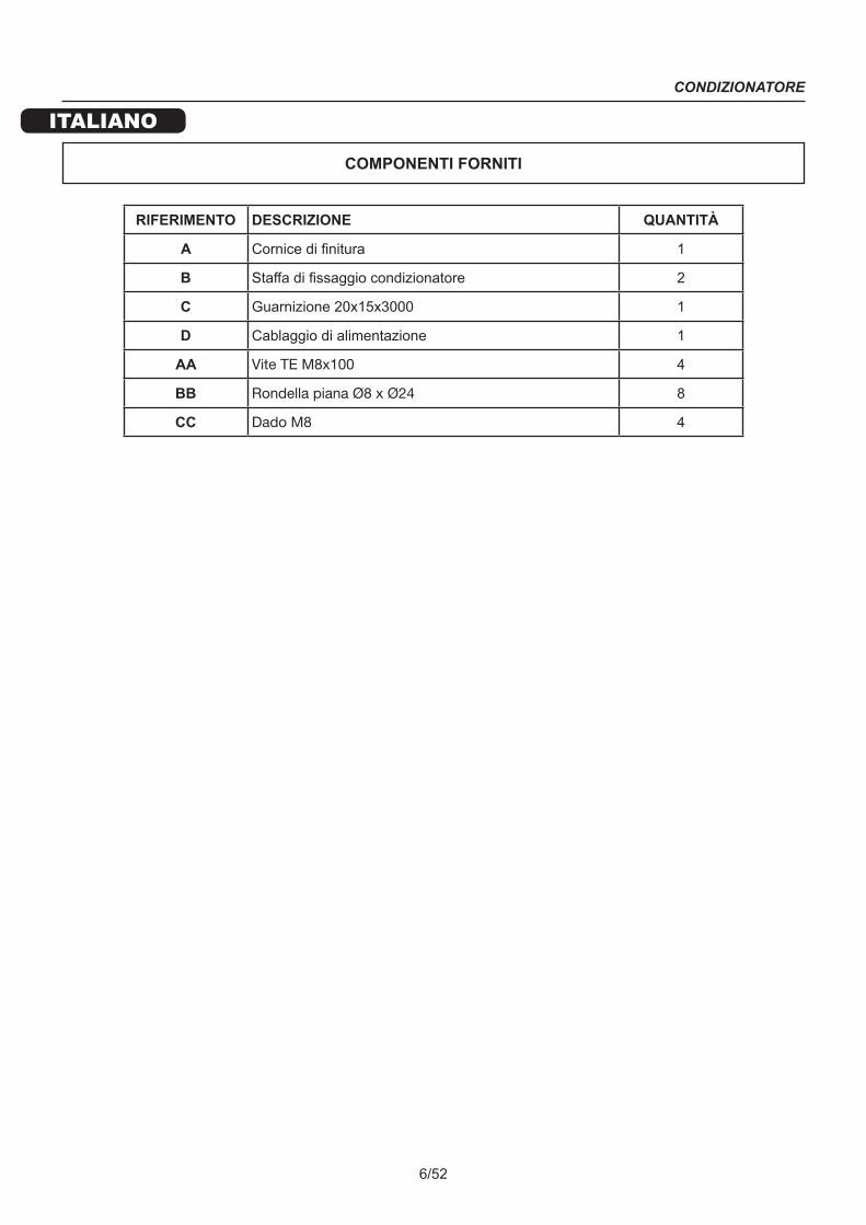
COMPONENTI FORNITI
RIFERIMENTO DESCRIZIONE QUANTITÀ
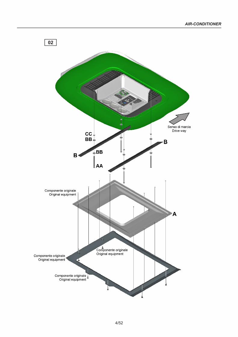
A Cornice di finitura 1
B Staffa di fissaggio condizionatore 2
C Guarnizione 20x15x3000 1
D Cablaggio di alimentazione 1
AA Vite TE M8x100 4
BB Rondella piana Ø8 x Ø24 8
CC Dado M8 4

CONDIZIONATORE
ITALIANO
7/52
INSTALLAZIONE
FASI DI MONTAGGIO
1. Scollegare la batteria del veicolo.
2. Smontare la cornice originale del veicolo (vedi fig. 1) svitando e recuperando le 8 viti di fissaggio evidenziate in fig. 2. Eliminare la cornice interna e la tendina parasole (fig. 3 - 4) recuperando soltanto la cornice più esterna illustrata in fig. 5.
1 2
3
4
5
CONDIZIONATORE
ITALIANO
8/52
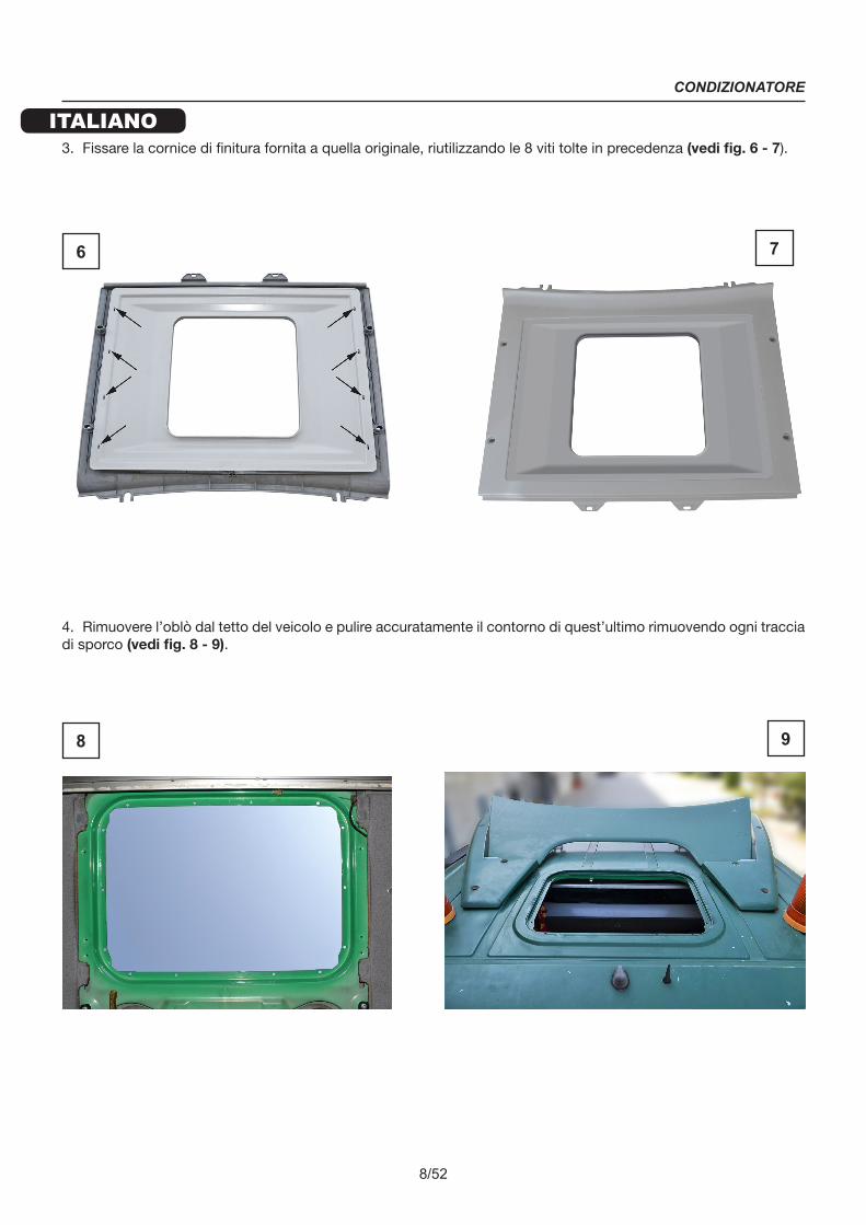
3. Fissare la cornice di finitura fornita a quella originale, riutilizzando le 8 viti tolte in precedenza (vedi fig. 6 - 7).
4. Rimuovere l’oblò dal tetto del veicolo e pulire accuratamente il contorno di quest’ultimo rimuovendo ogni traccia di sporco (vedi fig. 8 - 9).
6 7
8 9
CONDIZIONATORE
ITALIANO
9/52
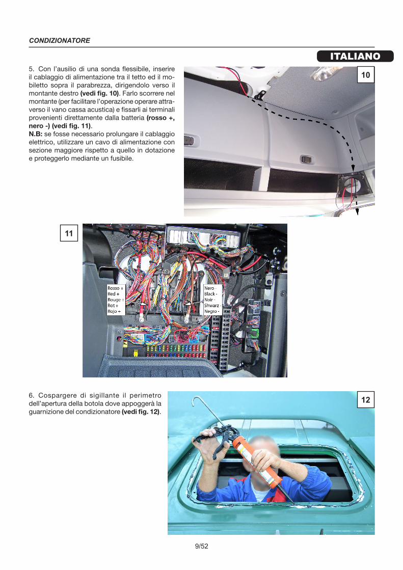
5. Con l’ausilio di una sonda flessibile, inserire il cablaggio di alimentazione tra il tetto ed il mo-biletto sopra il parabrezza, dirigendolo verso il montante destro (vedi fig. 10). Farlo scorrere nel montante (per facilitare l’operazione operare attra-verso il vano cassa acustica) e fissarli ai terminali provenienti direttamente dalla batteria (rosso +, nero -) (vedi fig. 11).N.B: se fosse necessario prolungare il cablaggio elettrico, utilizzare un cavo di alimentazione con sezione maggiore rispetto a quello in dotazione e proteggerlo mediante un fusibile.
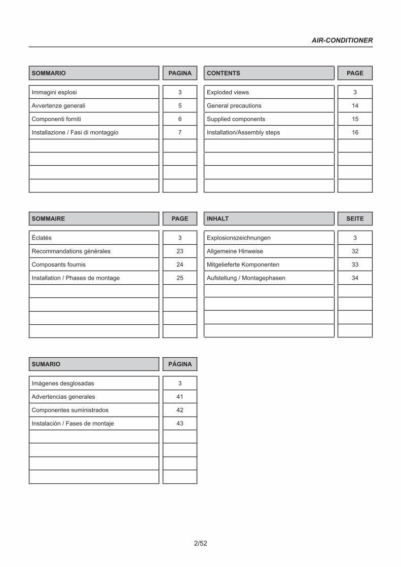
6. Cospargere di sigillante il perimetro dell’apertura della botola dove appoggerà la guarnizione del condizionatore (vedi fig. 12).
10
11
12

CONDIZIONATORE
ITALIANO
10/52
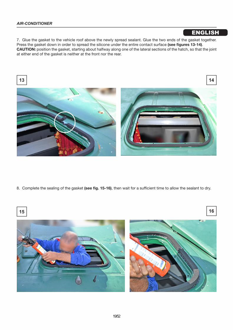
7. Incollare la guarnizione al tetto del veicolo sopra al sigillante appena distribuito. Incollare anche tra loro le due estremità della guarnizione. Premere la guarnizione per distribuire il silicone sotto tutta la superficie di contatto (vedi fig. 13 - 14).ATTENZIONE: posizionare la guarnizione partendo da circa metà di uno dei tratti laterali della botola, in modo che la giunzione delle due estremità della guarnizione non si trovi nella parte anteriore o posteriore.
8. Completare la sigillatura della guarnizione (vedi fig. 15 - 16). Attendere quindi alcuni minuti per permettere al silicone di essiccare.
13 14
15 16

CONDIZIONATORE
ITALIANO
11/52
9. Portare il condizionatore sul tetto del veicolo e collocarlo nell’apertura della botola (vedi fig. 17 - 18). Allineare il diffusore secondo la quota indicata (vedi fig. 19 - 20).ATTENZIONE: durante questa fase porre molta cautela per NON rovinare la guarnizione già posizionata sul tetto.
10. Collegare il cablaggio di alimentazione già inserito al condizionatore (vedi fig. 19 - 20).
17 18
19 20
CONDIZIONATORE
ITALIANO
12/52
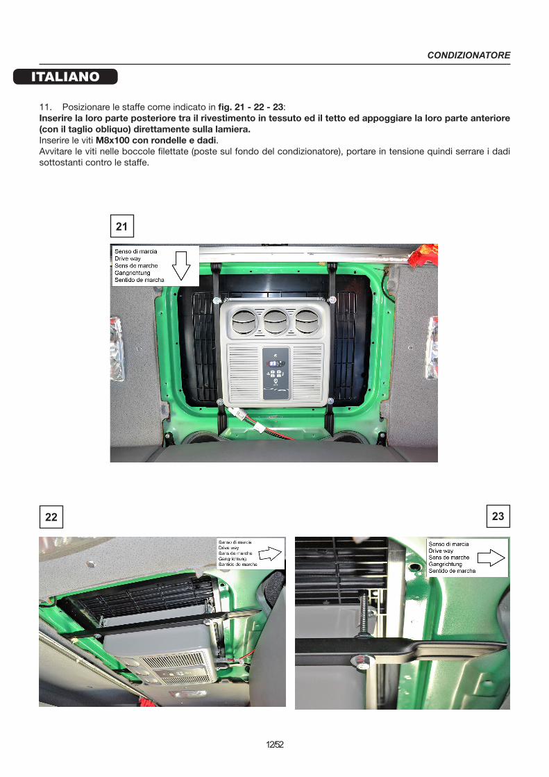
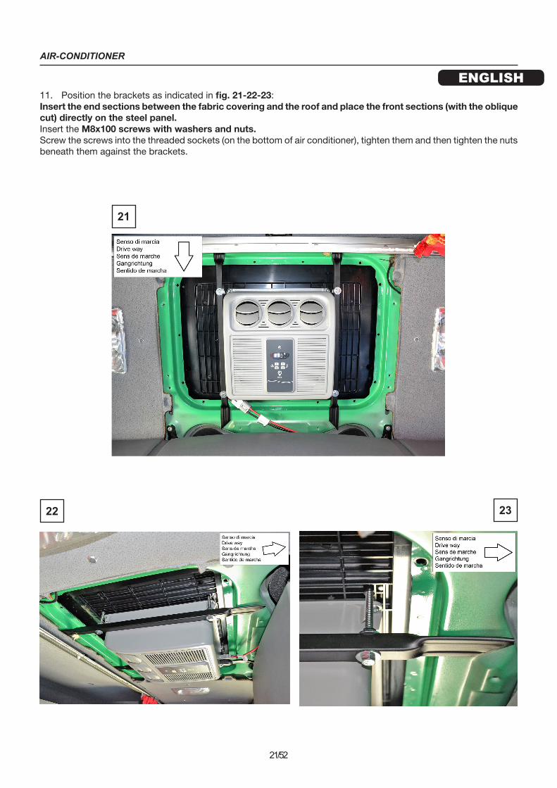
11. Posizionare le staffe come indicato in fig. 21 - 22 - 23:Inserire la loro parte posteriore tra il rivestimento in tessuto ed il tetto ed appoggiare la loro parte anteriore (con il taglio obliquo) direttamente sulla lamiera.Inserire le viti M8x100 con rondelle e dadi.Avvitare le viti nelle boccole filettate (poste sul fondo del condizionatore), portare in tensione quindi serrare i dadi sottostanti contro le staffe.
22 23
21

CONDIZIONATORE
ITALIANO
13/52
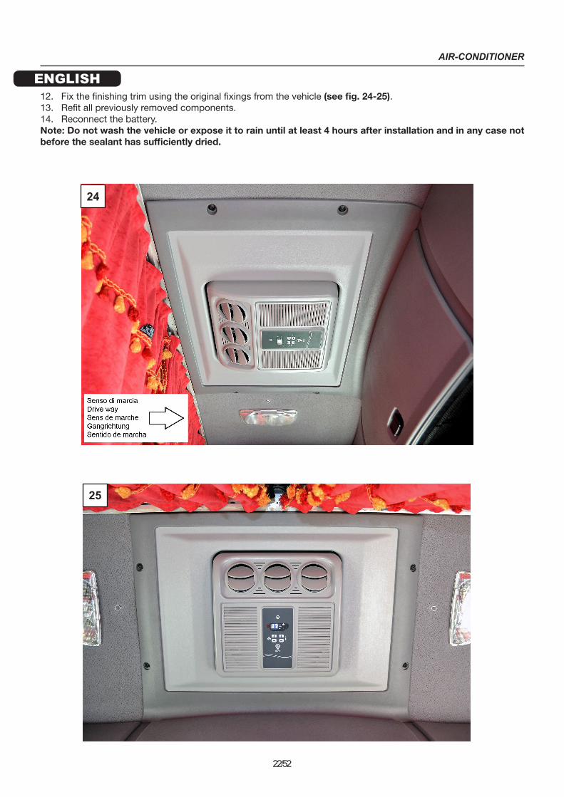
12. Fissare la cornice di finitura utilizzando i fissaggi originali del veicolo (vedi fig. 24 - 25).13. Rimontare i componenti precedentemente smontati.14. Ricollegare la batteria.N.B.: Lavare o esporre a pioggia non prima di 4 ore dal termine del montaggio e comunque non prima che il sigillante si sia sufficientemente asciugato.
24
25
AIR-CONDITIONER
ENGLISH
14/52
GENERAL PRECAUTIONS
It is important to carefully follow the installation instructions given in this manual. The manufacturer declines all responsibility for damage to persons or property caused by non-compliant installation or modification of the system.
The installation work must be performed exclusively by a specialized technician who is aware of the risks involved and the relevant regulations.
The air-conditioner must only be used as specified by the manufacturer and no arbitrary alterations or changes should be made to the device.
Do not place your hands in the ventilation grilles or insert any foreign objects into the system.
BEFORE INSTALLING THE DEVICE, REMOVE ALL CONNECTIONS TO THE VEHICLE BATTERY.
Install the roof unit securely to prevent it from overturning or falling.
During installation and when drilling holes in the vehicle, take care not to damage any wiring or tubes from previously installed systems.
When working close to the batteries (evaporator and/or condenser), be careful not to cut yourself on the edges of the fins.
If the electrical cables have to pass through panels with sharp edges, use suitable ducting or conduit.
Securely fasten the electrical cables, taking particular care where they run along conductive metal panels; avoid contact with sharp edges.
Once the unit is positioned on the roof, before starting to install it, check that the openings for the air inlet and outlet on the condenser are not blocked or covered.
Check whether you will need to change the stated height on the vehicle registration documents once the air condi-tioner is installed (contact the vehicle manufacturer).
Turn off the air conditioner before using automatic washing devices to clean the vehicle.
Ensure that the vehicle battery has a capacity of at least 170Ah.
A polyurethane sealant suitable for joints in sheet metal, car bonnets, canopies and painted surfaces is recommen-ded for the installation.
Before positioning the air conditioner on the vehicle roof, make sure that you can access it and that it can support the weight of the model you intend to install.

AIR-CONDITIONER
ENGLISH
15/52
SUPPLIED COMPONENTS
REFERENCE DESCRIPTION QUANTITY
A Finishing trim 1
B Air conditioner fixing bracket 2
C Gasket 20x15x3000 1
D Electrical wiring 1
AA Hex head screw M8x100 4
BB Flat washer Ø8 x Ø24 8
CC Nut M8 4

AIR-CONDITIONER
ENGLISH
16/52
INSTALLATION
ASSEMBLY STEPS
1. Disconnect the vehicle battery.
2. Remove the original frame from the vehicle (see fig. 1) by unscrewing the 8 screws indicated in fig. 2, which will be reused. Remove the interior frame and the sunshade (fig. 3 - 4) keeping only the outer frame shown in Fig. 5 for reuse.
1 2
3
4
5
AIR-CONDITIONER
ENGLISH
17/52
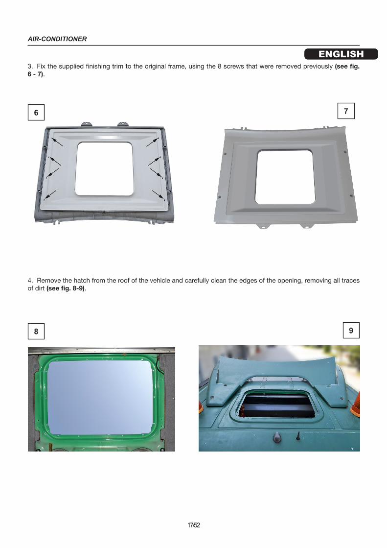
3. Fix the supplied finishing trim to the original frame, using the 8 screws that were removed previously (see fig. 6 - 7).
4. Remove the hatch from the roof of the vehicle and carefully clean the edges of the opening, removing all traces of dirt (see fig. 8-9).
6 7
8 9

AIR-CONDITIONER
ENGLISH
18/52
5. With the help of a flexible probe, insert the power cable between the roof and the cabinet above the windscreen, directing it towards the right-hand door frame (see fig. 10). Slide it down the inside of the door frame (working through the loudspeaker opening for easier access) and fix the wires to the terminals coming directly from the battery (red +, black -) (see fig. 11).Note: if the electrical wiring needs to be extended, use a power cable of larger diameter than that provided and protect it by means of a fuse.
6. Spread sealant along the edge of the ha-tch opening where the air conditioner gasket will be placed (see fig. 12).
10
11
12
AIR-CONDITIONER
ENGLISH
19/52
7. Glue the gasket to the vehicle roof above the newly spread sealant. Glue the two ends of the gasket together. Press the gasket down in order to spread the silicone under the entire contact surface (see figures 13-14).CAUTION: position the gasket, starting about halfway along one of the lateral sections of the hatch, so that the joint at either end of the gasket is neither at the front nor the rear.
8. Complete the sealing of the gasket (see fig. 15-16), then wait for a sufficient time to allow the sealant to dry.
13 14
15 16

AIR-CONDITIONER
ENGLISH
20/52
9. Lift the air conditioner onto the roof of the vehicle and position it in the opening of the hatch (see fig. 17-18). Align the diffuser in accordance with the indicated height (see fig. 19-20).CAUTION: during this step, take particular care NOT to damage the gasket already positioned on the roof.
10. Connect the electrical wiring already inserted in the air conditioner (see fig. 19 - 20).
17 18
19 20
AIR-CONDITIONER
ENGLISH
21/52
11. Position the brackets as indicated in fig. 21-22-23:Insert the end sections between the fabric covering and the roof and place the front sections (with the oblique cut) directly on the steel panel.Insert the M8x100 screws with washers and nuts.Screw the screws into the threaded sockets (on the bottom of air conditioner), tighten them and then tighten the nuts beneath them against the brackets.
22 23
21
AIR-CONDITIONER
ENGLISH
22/52
12. Fix the finishing trim using the original fixings from the vehicle (see fig. 24-25).13. Refit all previously removed components.14. Reconnect the battery.Note: Do not wash the vehicle or expose it to rain until at least 4 hours after installation and in any case not before the sealant has sufficiently dried.
24
25
CLIMATISEUR
FRANÇAIS
23/52
RECOMMANDATIONS GÉNÉRALES
Pour l’installation, il est important de veiller à respecter scrupuleusement les indications figurant dans le présent manuel. Le constructeur décline toute responsabilité en cas de dommages matériels et/ou corporels causés par une installation ou une modification non conforme de l'appareil.
Les interventions d’installation doivent être exclusivement confiées à un technicien qualifié et informé des dangers et des prescriptions correspondants.
Utiliser le climatiseur uniquement pour l’utilisation prévue par le fabricant et n’apporter aucune modification ni aucune transformation à l’appareil de manière arbitraire.
Ne jamais introduire les mains dans la grille des bouches d’aération et n’introduire aucun objet étranger dans l’appareil.
AVANT D’INSTALLER L’APPAREIL, RETIRER TOUS LES BRANCHEMENTS À LA BATTERIE DU VÉHICULE.
Installer le groupe sur le toit de manière sûre pour éviter qu’il ne puisse se renverser ou tomber.
Pendant les phases de montage et de réalisation de trous sur le véhicule, veiller à ne pas endommager les câblages ni les tuyaux installés précédemment.
Lors d’opérations effectuées à proximité des batteries (d’évaporation et/ou de condensation), faire attention pour prévenir les risques de coupure sur le bord des ailettes.
Si les câbles électriques doivent passer à travers des parois qui présentent des angles vifs, utiliser des tuyaux de protection ou des gaines spécialement prévues à cet effet.
Fixer solidement les câbles électriques en veillant à bien en définir le parcours, en particulier le long de parois métall-iques conductrices ; éviter par ailleurs tout contact avec des parties coupantes.
Avant d’entamer l’installation, s’assurer, une fois le groupe positionné sur le toit, que les ouvertures d’arrivée et de sortie d’air sur le condensateur ne sont pas bouchées ni couvertes.Après le montage du climatiseur, il est nécessaire de modifier l’enregistrement de la hauteur du véhicule indiquée sur la carte grise (contacter le constructeur du véhicule).
Éteindre le climatiseur avant de laver le véhicule sur un système de lavage automatique.S’assurer que la batterie du véhicule a une capacité d’au moins 170 Ah.
Pour le montage, il est recommandé d’utiliser un isolant à base de polyuréthane adapté aux joints métalliques, ca-pots, toits et autres surfaces peintes.
Avant de positionner le climatiseur sur le toit du véhicule, s’assurer qu’il est possible d’accéder au toit et que celui-ci est en mesure de supporter le poids du climatiseur à installer.

CLIMATISEUR
FRANÇAIS
24/52
COMPOSANTS FOURNIS
RÉFÉRENCE DÉSIGNATION QUANTITÉ
A Cadre de finition 1
B Bride de fixation climatiseur 2
C Joint 20x15x3000 1
D Câblage d’alimentation 1
AA Vis TE M8x100 4
BB Rondelle plate Ø8 x Ø24 8
CC Écrou M8 4
CLIMATISEUR
FRANÇAIS
25/52
INSTALLATION
PHASES DE MONTAGE
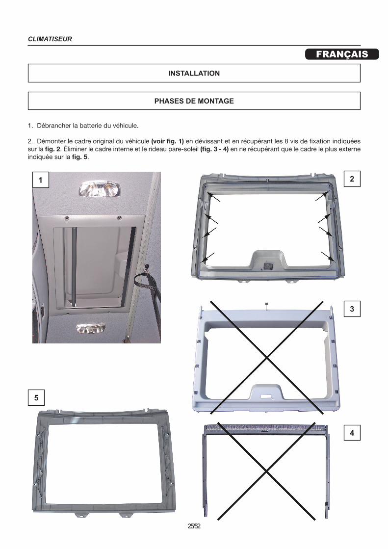
1. Débrancher la batterie du véhicule.
2. Démonter le cadre original du véhicule (voir fig. 1) en dévissant et en récupérant les 8 vis de fixation indiquées sur la fig. 2. Éliminer le cadre interne et le rideau pare-soleil (fig. 3 - 4) en ne récupérant que le cadre le plus externe indiquée sur la fig. 5.
1 2
3
4
5
CLIMATISEUR
FRANÇAIS
26/52
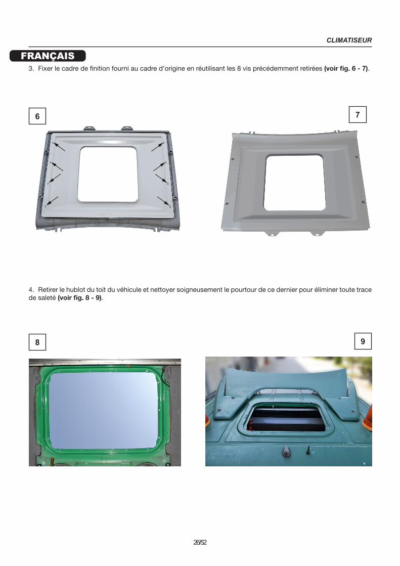
3. Fixer le cadre de finition fourni au cadre d’origine en réutilisant les 8 vis précédemment retirées (voir fig. 6 - 7).
4. Retirer le hublot du toit du véhicule et nettoyer soigneusement le pourtour de ce dernier pour éliminer toute trace de saleté (voir fig. 8 - 9).
6 7
8 9

CLIMATISEUR
FRANÇAIS
27/52
5. A l’aide d’une sonde flexible, introduire le câblage d’alimentation entre le toit et le meuble sur le pare-brise, en l’orientant vers le montant droit (voir fig. 10). Le faire passer dans le mon-tant (pour faciliter l’opération, passer à travers le logement du haut-parleur) le fixer aux bornes provenant directement de la batterie (rouge +, noir -) (voir fig. 11).NB : dans le cas où il serait nécessaire de pro-longer le câblage électrique, utiliser un câble d’alimentation de section supérieure à celle du câble fourni et le protéger au moyen d’un fusible.
6. Couvrir de produit d’isolation le périmètre de l’ouverture de la trappe à hauteur de la-quelle doit reposer le joint du climatiseur (voir fig. 12).
10
11
12
CLIMATISEUR
FRANÇAIS
28/52
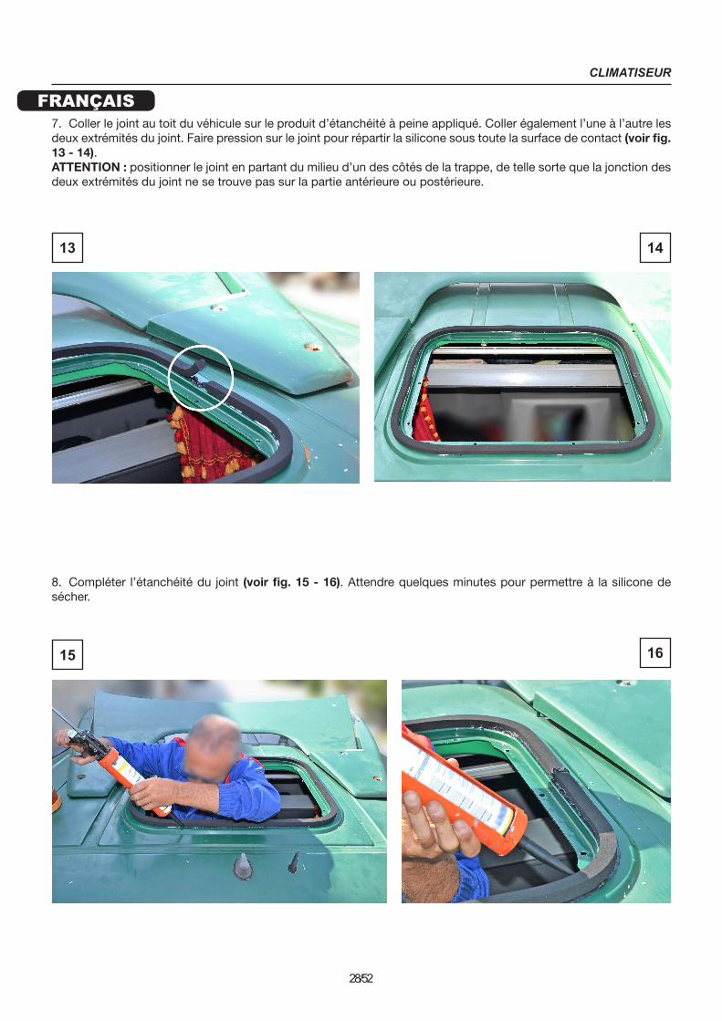
7. Coller le joint au toit du véhicule sur le produit d’étanchéité à peine appliqué. Coller également l’une à l’autre les deux extrémités du joint. Faire pression sur le joint pour répartir la silicone sous toute la surface de contact (voir fig. 13 - 14).ATTENTION : positionner le joint en partant du milieu d’un des côtés de la trappe, de telle sorte que la jonction des deux extrémités du joint ne se trouve pas sur la partie antérieure ou postérieure.
8. Compléter l’étanchéité du joint (voir fig. 15 - 16). Attendre quelques minutes pour permettre à la silicone de sécher.
13 14
15 16

CLIMATISEUR
FRANÇAIS
29/52
9. Amener le climatiseur sur le toit du véhicule et le placer sur l’ouverture de la trappe (voir fig. 17 - 18). Aligner le diffuseur à la cote indiquée (voir fig. 19 - 20).ATTENTION : lors de cette phase, faire très attention à NE PAS endommager le joint déjà positionné sur le toit.
10. Brancher le câblage d’alimentation déjà introduit au climatiseur (voir fig. 19 - 20).
17 18
19 20
CLIMATISEUR
FRANÇAIS
30/52
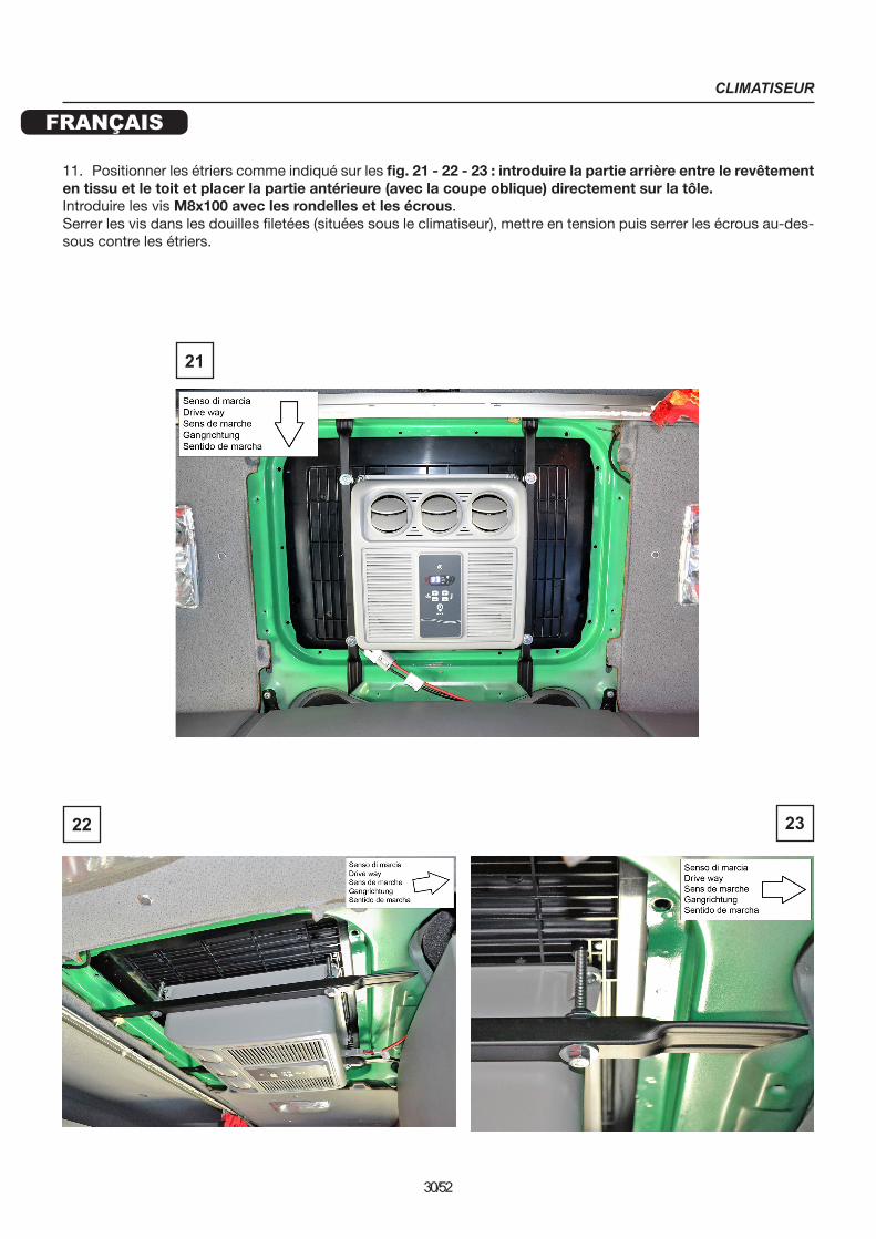
11. Positionner les étriers comme indiqué sur les fig. 21 - 22 - 23 : introduire la partie arrière entre le revêtement en tissu et le toit et placer la partie antérieure (avec la coupe oblique) directement sur la tôle.Introduire les vis M8x100 avec les rondelles et les écrous.Serrer les vis dans les douilles filetées (situées sous le climatiseur), mettre en tension puis serrer les écrous au-des-sous contre les étriers.
22 23
21
CLIMATISEUR
FRANÇAIS
31/52
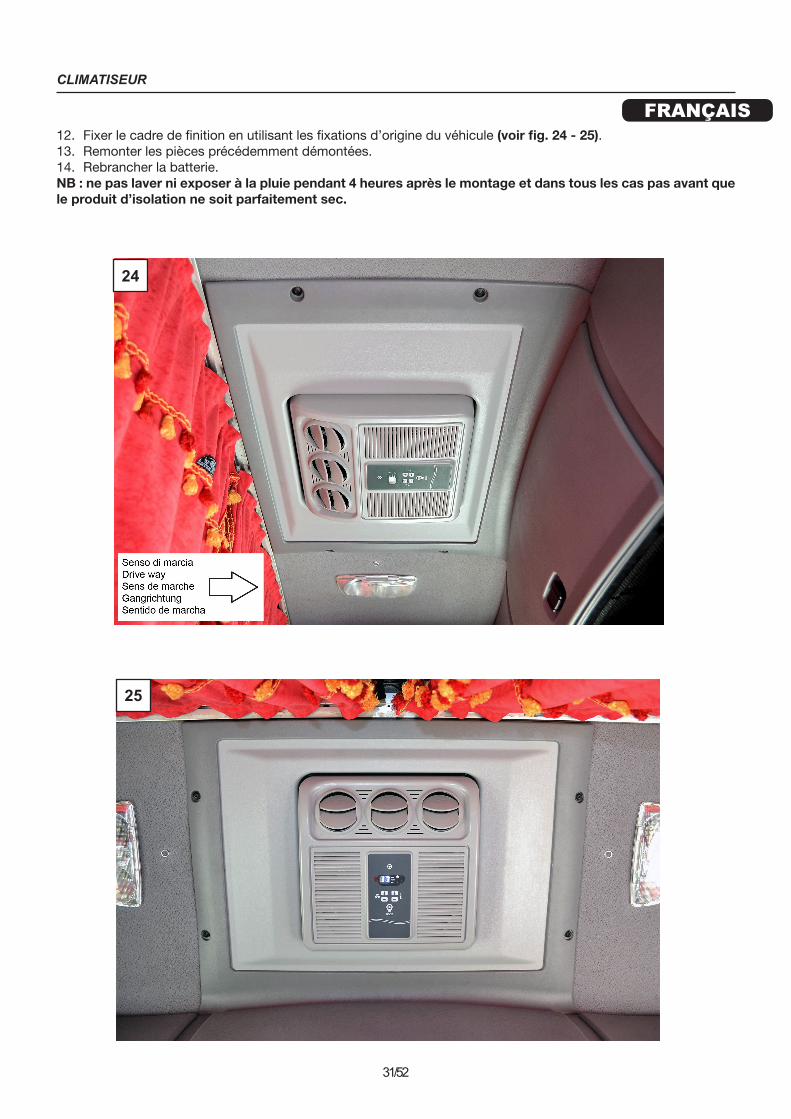
12. Fixer le cadre de finition en utilisant les fixations d’origine du véhicule (voir fig. 24 - 25).13. Remonter les pièces précédemment démontées.14. Rebrancher la batterie.NB : ne pas laver ni exposer à la pluie pendant 4 heures après le montage et dans tous les cas pas avant que le produit d’isolation ne soit parfaitement sec.
24
25

KLIMAANLAGE
DEUTSCH
32/52
ALLGEMEINE HINWEISE
Für die Installation ist es wichtig, dass die in diesem Handbuch genannten Anweisungen strikt befolgt werden. Der Hersteller lehnt jede Haftung für Sach- und Personenschäden ab, die durch unsachgemäße Installationen oder Veränderungen der Anlage entstehen.
Die Installationsarbeiten dürfen nur von einem spezialisierten und über die damit verbundenen Gefahren und über die entsprechenden Vorschriften informierten Techniker ausgeführt werden.
Die Klimaanlage darf nur für den vom Hersteller vorgesehenen Zweck eingesetzt werden und es dürfen keine wil-lkürlichen Veränderungen oder Umwandlungen des Gerätes stattfinden.
Die Hände nicht in das Gitter der Auslassöffnungen stecken und keine Gegenstände in die Anlage einführen.
VOR DER MONTAGE DER ANLAGE ALLE VERBINDUNGEN ZUR BATTERIE DES FAHRZEUGS ABKLEMMEN.
Das Dachaggregat auf sichere Weise montieren, sodass es weder umkippen noch fallen kann.
Während der Montagephasen und der Bohrung von Löchern auf dem Fahrzeug darauf achten, dass keine Kabel oder Leitungen von bereits montierten Anlagen beschädigt werden.
Wenn Arbeiten in der Nähe der Batterien erfolgen (Wärmetauscher und/oder Kondensator), ist darauf zu achten, dass man sich nicht an den Rändern der Rippen verletzt.
Falls die Elektrokabel durch Wände mit scharfen Kanten verlaufen müssen, sind Schutzrohre oder spezielle Kabel-führungen zu verwenden.
Die Elektrokabel müssen gut befestigt werden, dabei besonders auf ihren Verlauf entlang metallischer Wände achten, die Elektrizität weiterleiten; Kontakt mit scharfkantigen Teilen vermeiden.
Vor der Montage, sobald das Aggregat auf dem Dach positioniert ist, überprüfen, dass die Öffnungen für den Luftein-gang- und Ausgang der Klimaanlage nicht versperrt oder bedeckt sind.
Überprüfen, ob es nach der Montage der Klimaanlage notwendig ist, die Eintragung der Fahrzeughöhe im Fahrzeu-gbrief zu verändern (Hersteller des Fahrzeugs kontaktieren).
Vor der Nutzung von automatischen Waschvorrichtungen für die Reinigung des Fahrzeugs muss die Klimaanlage ausgeschaltet werden.
Überprüfen, dass die Batterie des Fahrzeugs eine Leistung von mindestens 170 Ah aufweist.
Für die Montage wird die Verwendung von Polyurethan-Dichtmaterial empfohlen, geeignet für Fugen auf Blech, Hauben, Schiebedächern und lackierten Oberflächen.
Vor der Positionierung der Klimaanlage auf dem Dach des Fahrzeugs überprüfen, ob es sich gut erreichen lässt und ob es das Gewicht der Klimaanlage, die installiert werden soll, tragen kann.
KLIMAANLAGE
DEUTSCH
33/52
MITGELIEFERTE KOMPONENTEN
REFERENZ BESCHREIBUNG MENGE
A Zierrahmen 1
B Spannbügel Klimaanlage 2
C Dichtung 20x15x3000 1
D Stromversorgungskabel 1
AA Sechskantschraube M8x100 4
BB Flachschraube Ø8 x Ø24 8
CC Mutter M8 4

KLIMAANLAGE
DEUTSCH
34/52
AUFSTELLUNG
1. Die Batterie des Fahrzeugs abklemmen.
2. Den Originalrahmen des Fahrzeugs (siehe Abb. 1) abmontieren. Dazu die in Abb. 2 angezeigten 8 Befestigun-gsschrauben lösen und zur Wiederverwendung bereithalten. Den Innenrahmen und die Sonnenschutzvorrichtung (Abb. 3 - 4) entfernen und lediglich den in Abb. 5 gezeigten äußeren Rahmen zur Wiederverwendung bereithalten.
1 2
3
4
5
MONTAGESPHASEN
KLIMAANLAGE
DEUTSCH
35/52
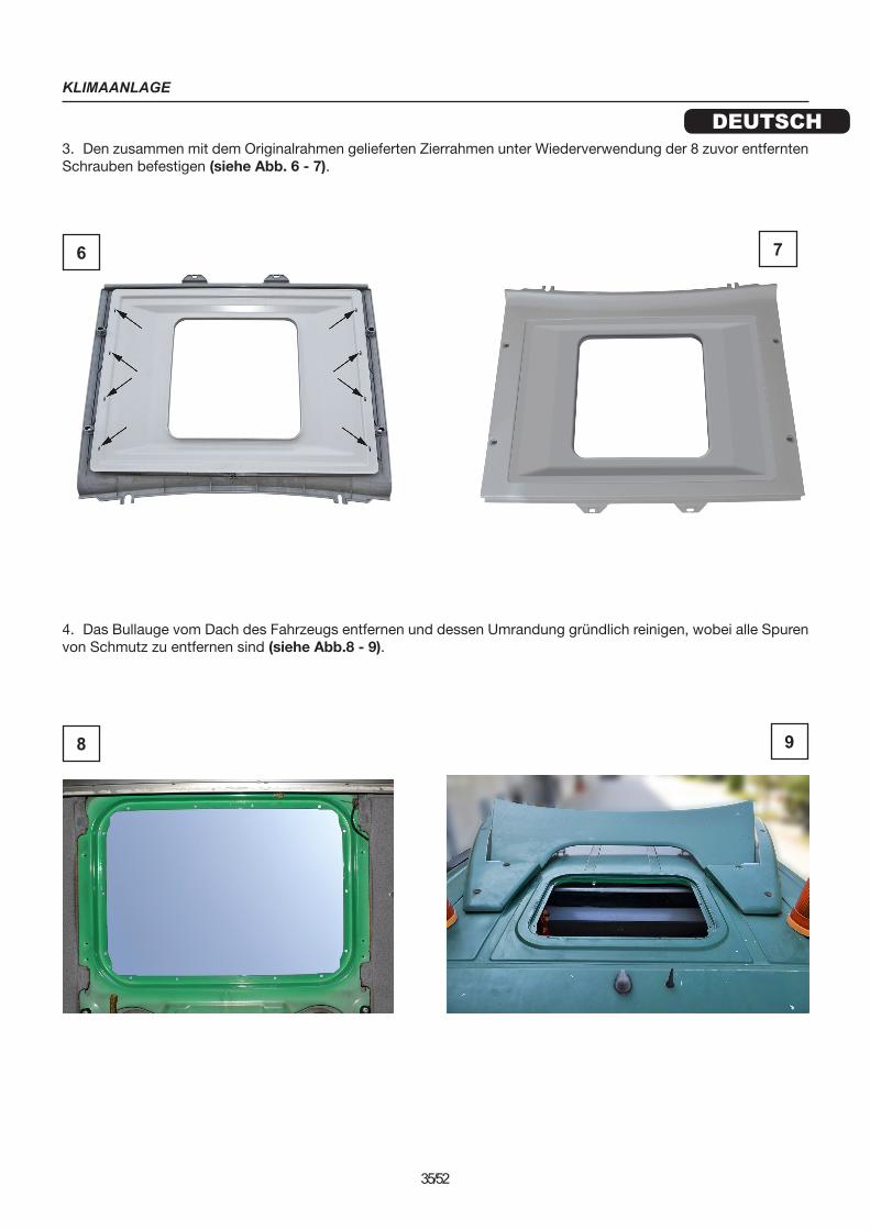
3. Den zusammen mit dem Originalrahmen gelieferten Zierrahmen unter Wiederverwendung der 8 zuvor entfernten Schrauben befestigen (siehe Abb. 6 - 7).
4. Das Bullauge vom Dach des Fahrzeugs entfernen und dessen Umrandung gründlich reinigen, wobei alle Spuren von Schmutz zu entfernen sind (siehe Abb.8 - 9).
6 7
8 9

KLIMAANLAGE
DEUTSCH
36/52
5. Das Stromversorgungskabel mithilfe einer flexi-blen Sonde zwischen dem Dach und dem Korpus über der Frontscheibe einführen und zur rechten Strebe hin führen (siehe Abb. 10). Dieses durch die Strebe führen (zur Erleichterung des Vorgangs durch das Lautsprecherfach arbeiten) und an den direkt von der Batterie kommenden Klemmen (rot +, schwarz -) befestigen (siehe Abb. 11).ANMERKUNG: Wenn die elektrische Verkabelung verlängert werden muss, ein Versorgungskabel mit einem Querschnitt verwenden, der über demje-nigen des mitgelieferten Kabels liegt und dieses Kabel mit einer Sicherung schützen.
6. Den Umriss der Öffnung der Luke dort, wo die Dichtung der Klimaanlage aufliegen wird, mit Dichtmaterial bestreichen (siehe Abb. 12).
10
11
12
KLIMAANLAGE
DEUTSCH
37/52
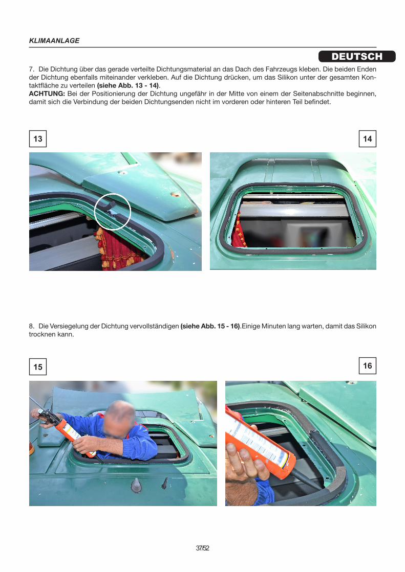
7. Die Dichtung über das gerade verteilte Dichtungsmaterial an das Dach des Fahrzeugs kleben. Die beiden Enden der Dichtung ebenfalls miteinander verkleben. Auf die Dichtung drücken, um das Silikon unter der gesamten Kon-taktfläche zu verteilen (siehe Abb. 13 - 14).ACHTUNG: Bei der Positionierung der Dichtung ungefähr in der Mitte von einem der Seitenabschnitte beginnen, damit sich die Verbindung der beiden Dichtungsenden nicht im vorderen oder hinteren Teil befindet.
8. Die Versiegelung der Dichtung vervollständigen (siehe Abb. 15 - 16).Einige Minuten lang warten, damit das Silikon trocknen kann.
13 14
15 16
KLIMAANLAGE
DEUTSCH
38/52
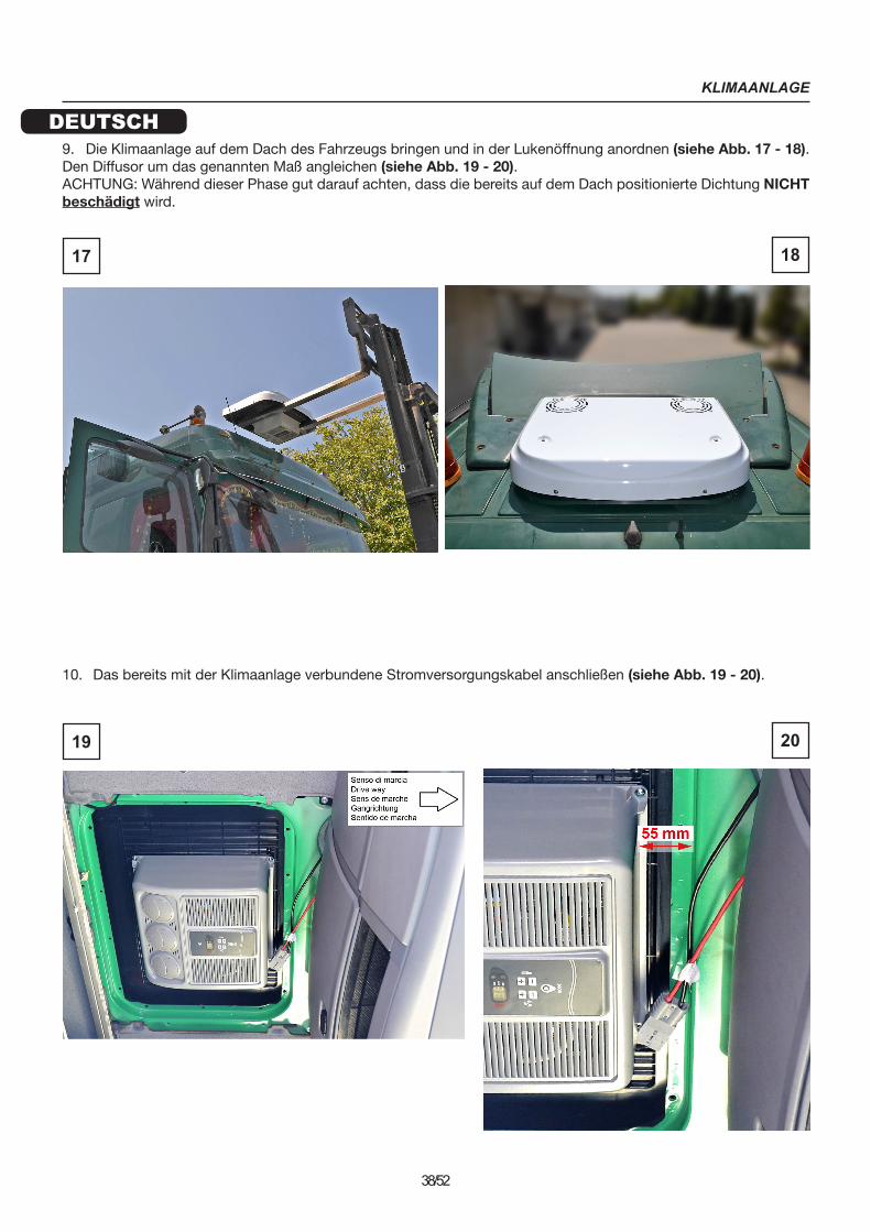
9. Die Klimaanlage auf dem Dach des Fahrzeugs bringen und in der Lukenöffnung anordnen (siehe Abb. 17 - 18). Den Diffusor um das genannten Maß angleichen (siehe Abb. 19 - 20).ACHTUNG: Während dieser Phase gut darauf achten, dass die bereits auf dem Dach positionierte Dichtung NICHT beschädigt wird.
10. Das bereits mit der Klimaanlage verbundene Stromversorgungskabel anschließen (siehe Abb. 19 - 20).
17 18
19 20
KLIMAANLAGE
DEUTSCH
39/52
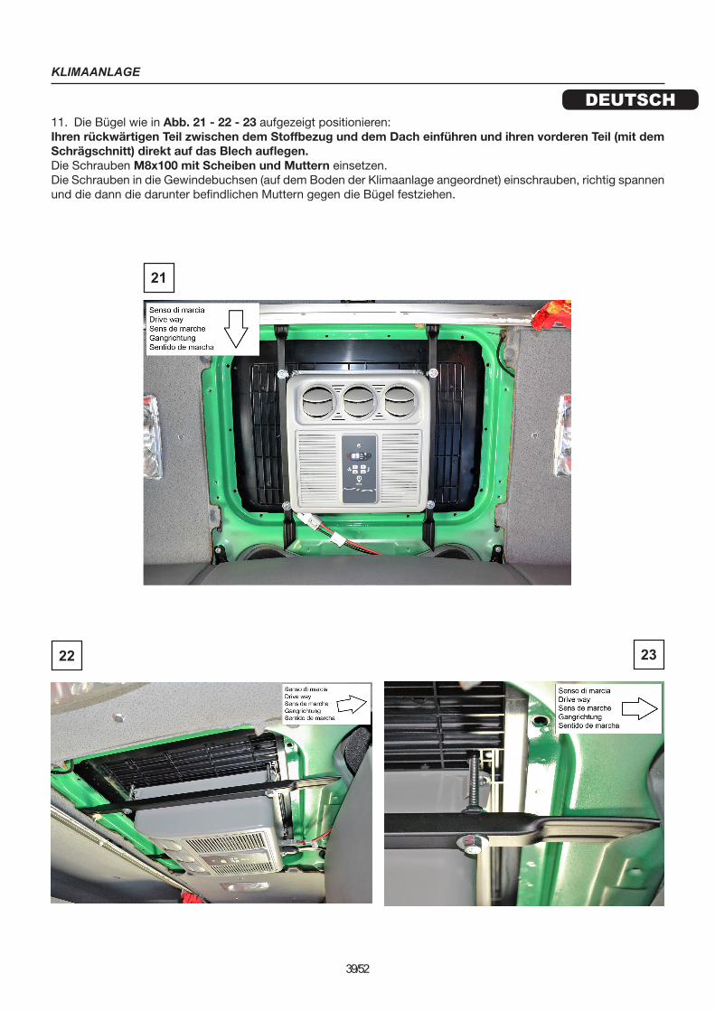
11. Die Bügel wie in Abb. 21 - 22 - 23 aufgezeigt positionieren:Ihren rückwärtigen Teil zwischen dem Stoffbezug und dem Dach einführen und ihren vorderen Teil (mit dem Schrägschnitt) direkt auf das Blech auflegen.Die Schrauben M8x100 mit Scheiben und Muttern einsetzen.Die Schrauben in die Gewindebuchsen (auf dem Boden der Klimaanlage angeordnet) einschrauben, richtig spannen und die dann die darunter befindlichen Muttern gegen die Bügel festziehen.
22 23
21
KLIMAANLAGE
DEUTSCH
40/52
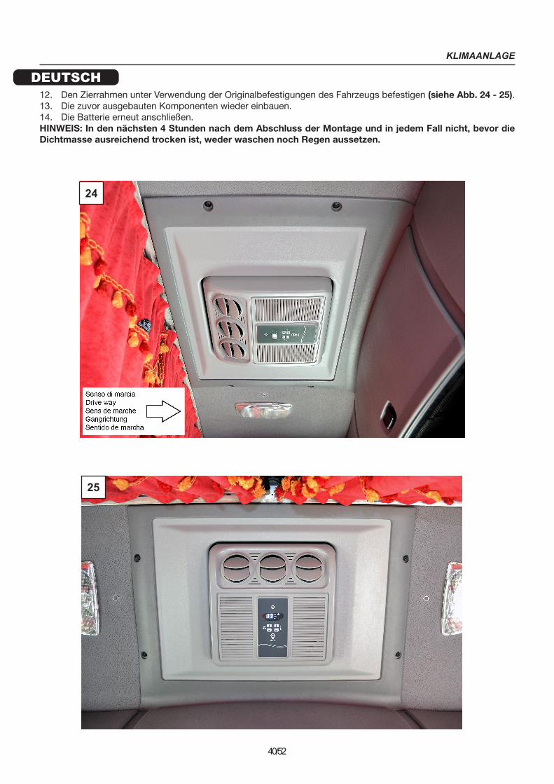
12. Den Zierrahmen unter Verwendung der Originalbefestigungen des Fahrzeugs befestigen (siehe Abb. 24 - 25).13. Die zuvor ausgebauten Komponenten wieder einbauen.14. Die Batterie erneut anschließen.HINWEIS: In den nächsten 4 Stunden nach dem Abschluss der Montage und in jedem Fall nicht, bevor die Dichtmasse ausreichend trocken ist, weder waschen noch Regen aussetzen.
24
25
ACONDICIONADOR
ESPAÑOL
41/52
ADVERTENCIAS GENERALES
Para la instalación, es importante seguir estrictamente las instrucciones que se indican en este manual. El fabricante declina toda responsabilidad en caso de daños a cosas y personas causados por instalaciones inadecuadas o cambios no conformes en el sistema.
Las operaciones de instalación deben ser efectuadas exclusivamente por un técnico especializado e informado sobre los peligros relacionados y los requisitos correspondientes.
Utilizar el aire acondicionado exclusivamente para el uso previsto por el fabricante y no realizar cambios o transfor-maciones del aparato de forma arbitraria.
No introducir las manos en la rejilla de las boquillas de ventilación y no introducir ningún objeto externo en el equipo.
ANTES DE INSTALAR EL EQUIPO, DESCONECTAR TODAS LAS CONEXIONES A LA BATERÍA DEL VEHÍCULO.
Instalar la unidad de techo de forma segura para impedir que pueda volcarse o caer.
Durante las fases de montaje y la realización de agujeros en el vehículo, tener cuidado de no dañar cables o tuberías de sistemas ya instalados con anterioridad.
Cuando se lleven a cabo operaciones cerca de las baterías (evaporadora y/o condensadora) prestar atención a no cortarse con los bordes de las aletas.
Si los cables eléctricos deben pasar a través de paredes con bordes afilados, utilizar tubos de protección o con-ductos específicos.
Fijar firmemente los cables eléctricos, prestando especial atención a su recorrido a través de paredes metálicas que conducen electricidad; evitar también el contacto con partes cortantes.
Antes de comenzar la instalación, comprobar que una vez colocada la unidad en el techo, las aberturas para la entrada y salida de aire en el condensador no estén obstruidas o cubiertas.
Comprobar si, después del montaje del aire acondicionado, es necesario modificar el ajuste de la altura del vehículo indicado en el permiso de circulación (ponerse en contacto con el fabricante del vehículo).
Apagar el aire acondicionado antes de utilizar dispositivos de lavado automático para la limpieza del vehículo.
Comprobar que la batería del vehículo tenga una capacidad de al menos 170 Ah.
Para el montaje, se recomienda utilizar sellador de poliuretano adecuado para juntas de chapa, capós, techos y superficies pintadas.
Antes de colocar en aire acondicionado en el techo del vehículo, comprobar que se pueda acceder por encima de este y que pueda soportar el peso del aire acondicionado que se pretende instalar.
ACONDICIONADOR
ESPAÑOL
42/52
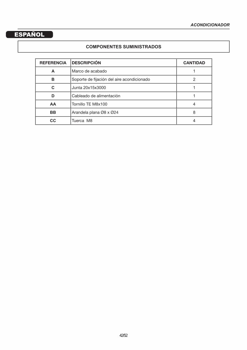
COMPONENTES SUMINISTRADOS
REFERENCIA DESCRIPCIÓN CANTIDAD
A Marco de acabado 1
B Soporte de fijación del aire acondicionado 2
C Junta 20x15x3000 1
D Cableado de alimentación 1
AA Tornillo TE M8x100 4
BB Arandela plana Ø8 x Ø24 8
CC Tuerca M8 4

ACONDICIONADOR
ESPAÑOL
43/52
INSTALACIÓN
FASES DE MONTAJE
1. Desconectar la batería del vehículo.
2. Desmontar el marco original del vehículo (ver fig. 1) destornillando y recuperando los 8 tornillos de fijación que se muestran en la fig. 2. Retirar el marco interior y la cortinilla parasol (fig. 3 - 4) recuperando solo el marco exterior que se muestra en la fig. 5.
1 2
3
4
5
ACONDICIONADOR
ESPAÑOL
44/52
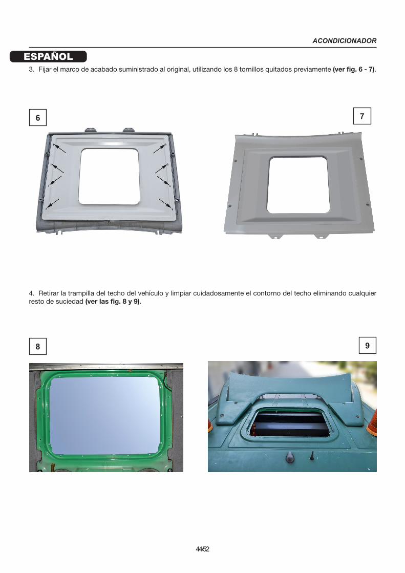
3. Fijar el marco de acabado suministrado al original, utilizando los 8 tornillos quitados previamente (ver fig. 6 - 7).
4. Retirar la trampilla del techo del vehículo y limpiar cuidadosamente el contorno del techo eliminando cualquier resto de suciedad (ver las fig. 8 y 9).
6 7
8 9

ACONDICIONADOR
ESPAÑOL
45/52
5. Con la ayuda de una sonda flexible, introducir el cableado de alimentación entre el techo y el gabinete por encima del parabrisas, dirigiéndolo hacia el montante derecho (ver fig. 10). Deslizarlo en el montante (para facilitar la operación, operar a través del compartimento de la caja acústica) y fijarlo a los terminales que proceden directamente de la batería (rojo +, negro -) (ver fig. 11).Nota: si es necesario prolongar el cableado eléctrico, utilizar un cable de alimentación con mayor sección que el suministrado y protegerlo mediante un fusible.
6. Esparcir sellador en el perímetro de la abertura de la trampilla donde se apoyará la junta del aire acondicionado (ver fig. 12).
10
11
12

ACONDICIONADOR
ESPAÑOL
46/52
7. Pegar la junta al techo del vehículo sobre el sellador que se ha distribuido recientemente. Pegar también los dos extremos de la junta. Presionar la junta para distribuir la silicona debajo de toda la superficie de contacto (ver fig. 13 - 14).ATENCIÓN: colocar la junta a partir de aproximadamente la mitad de uno de los laterales de la trampilla, de manera que el empalme de los dos extremos de la junta no se encuentre en la parte delantera o trasera.
8. Completar el sellado de la junta (ver fig. 15 - 16). Esperar unos minutos para que la silicona se seque.
13 14
15 16
ACONDICIONADOR
ESPAÑOL
47/52
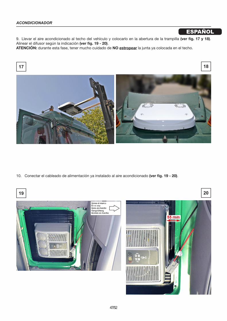
9. Llevar el aire acondicionado al techo del vehículo y colocarlo en la abertura de la trampilla (ver fig. 17 y 18). Alinear el difusor según la indicación (ver fig. 19 - 20).ATENCIÓN: durante esta fase, tener mucho cuidado de NO estropear la junta ya colocada en el techo.
10. Conectar el cableado de alimentación ya instalado al aire acondicionado (ver fig. 19 - 20).
17 18
19 20

ACONDICIONADOR
ESPAÑOL
48/52
11. Colocar los soportes como se indica en las fig. 21 - 22 - 23:Introducir su parte trasera entre el revestimiento de tejido y el techo, y apoyar su parte delantera (con el corte oblicuo) directamente sobre la chapa.Introducir los tornillos M8x100 con arandelas y tuercas.Apretar los tornillos en los casquillos roscados (situados en la parte inferior del aire acondicionado), ajustarlos y apretar las tuercas de abajo contra los soportes.
22 23
21

ACONDICIONADOR
ESPAÑOL
49/52
12. Fijar el marco de acabado utilizando las fijaciones originales del vehículo (ver fig. 24 - 25).13. Montar los componentes que se han desmontado anteriormente.14. Volver a conectar la batería.NOTA: No lavar o exponer a la lluvia antes de 4 horas desde la finalización del montaje y, en cualquier caso, no antes de que el sellador se haya secado suficientemente.
24
25

AIR-CONDITIONER
50/52

AIR-CONDITIONER
51/52

AIR-CONDITIONER
________ - Settembre 2018