Embed Size (px)
Citation preview
Measurement of Concrete Damage Mechanics by Internal
Friction and Laser Shearography
Richard A. LivingstonMaterials Science & Engineering Dept
University of Maryland
12th
Int. Symposium on Nondestructive Characterization of Materials
Blacksburg, VA June 23, 2011

Co‐Authors, Civil Engineering Dept.
•
Nicolas McMorris
•
Cintia
Lijeron
•
Amde
M. Amde
•
Jorgemai
Ceesay
•
Hung Khong

Outline
•
Introduction
•
Experimental Approach
•
Q‐factor Analysis
•
Shearography
Analysis
•
Conclusions

Distributed Damage in Concrete•
Characteristic of:–
Alkali Silica Reaction (ASR)
–
Delayed Ettringite
Formation (DEF)
–
Freeze‐thaw Damage (F‐T)
•
Mechanism is the formation of expansive phases:‐
Ettringite
‐
ASR gel
‐
Ice
•
Results in multiple subvisible
microcracks
•
Damage is usually measured on laboratory specimens by
reduction in strength or stiffness
•
Therefore an NDT method is needed to measure distributed
damage in the field

Damped Free Oscillator( ) exp( ) cos ou t A t t
where :
u(t) = displacementA
= amplitude
α
= damping factor or internal friction
ωo
= fundamental frequency in radians per secondt
= time.
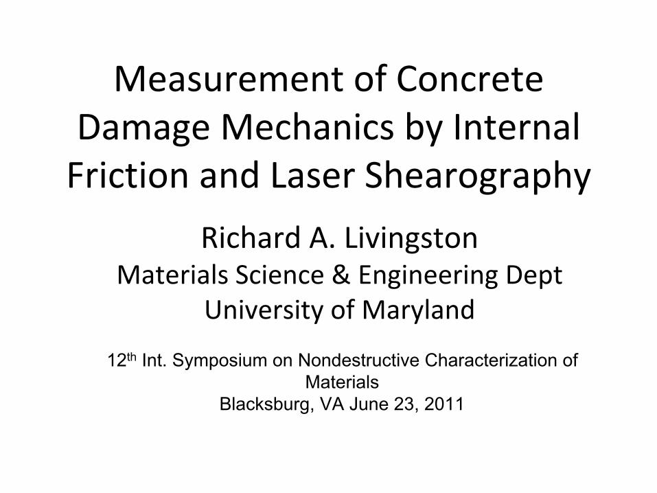
2o Q
Q‐factor
2 1
o
Q

Experimental Approach
•
Standard 3”
x 3”
x 11”
concrete prisms
•
Two types of accelerated damage–
Freeze‐thaw cycles ASTM C 666
–
Duggan expansion test
•
Two potassium levels–
Control = 0.56 % K2
O
–
High Potassium =2.06% K2
O

Duggan Test Water Storage

Test Methods
•
Ultrasound : ASTM C 215: Fundamental Transverse Frequency and Quality Factor
•
Expansion: ASTM C 490
•
Weight change
•
Compressive strength
•
Fracture surface Scanning Electron Microscopy
•
Laser shearography

ASTM C 215

Q‐factor for F‐T samples

Q‐factor for DEF samples

All Q vs
Normalized Damage
Q‐factor
2 1
o
Q
Q 2o
12
2
114o Q
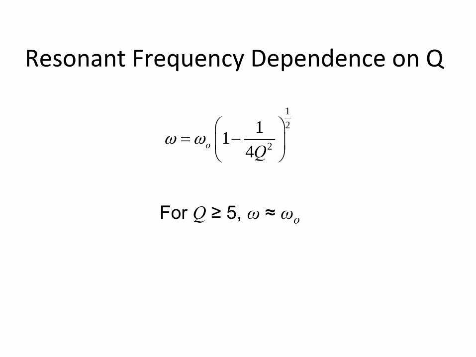
Resonant Frequency Dependence on Q
For Q
≥
5, ω
≈
ωo

DEF Specimens, Damping

DEF Specimens, Frequency

ASTM C‐215 Equation for Resonant Frequency
3
3
* **0.9464* *
E b tfM L c
where: f = resonant frequency, HzE = Dynamic elastic modulusM
= mass of prism, KgL = Length of prism, mb
= Width of prism, mt = Depth of prism, mc = Correction factor, depends on radius of gyration
and Poisson’s ratio

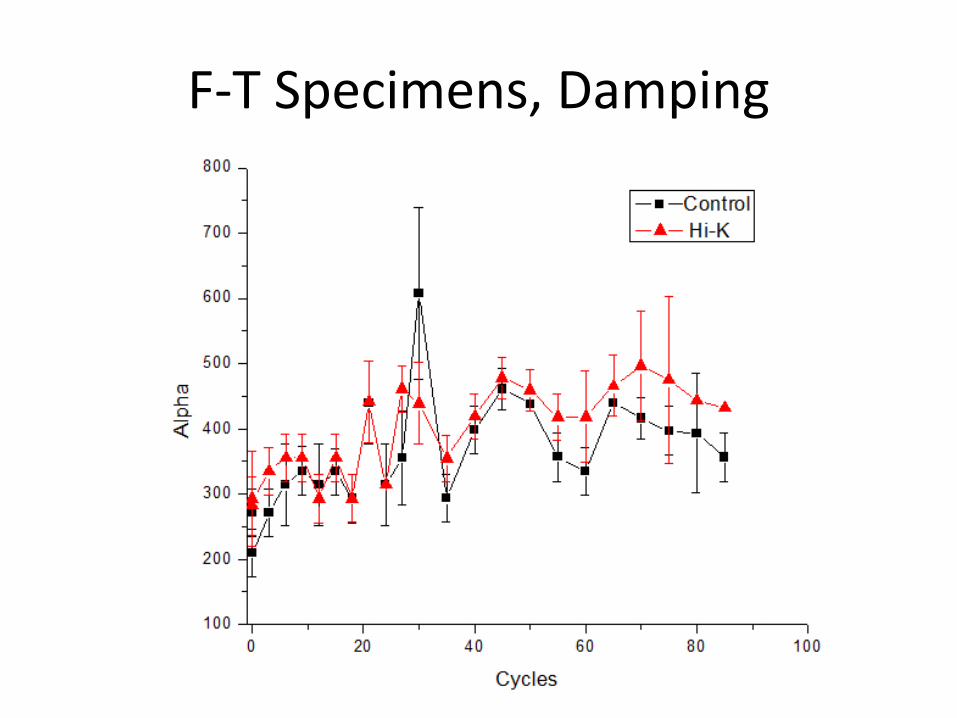
F‐T Specimens, Damping

F‐T Specimens, Frequency
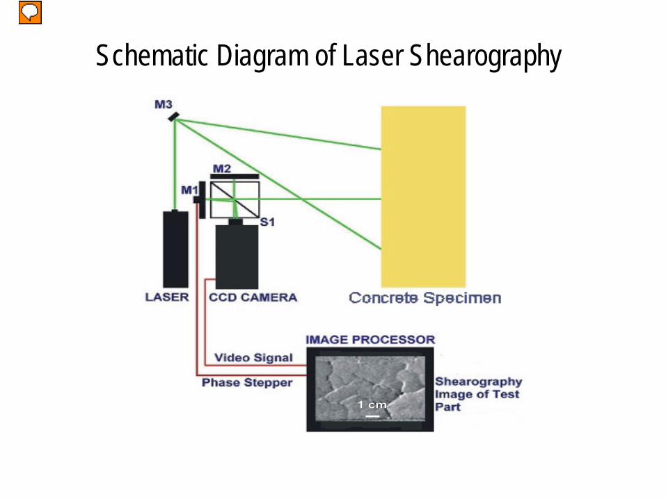
Schematic Diagram of Laser Shearography

Shearogram
Crack Image Analysis, F-T Control, 100 Days
Crack Detection Segmented Image

Crack Density, Control Crack Density, Hi-K
DEF
Freeze-Thaw
DEF
Freeze-Thaw

Summary,DEF•
DEF does not significantly change internal
friction
•
Resonant frequency increases over time because elastic modulus increases due to continued concrete curing
•
Therefore linear resonance spectroscopy is not feasible as an NDT method for DEF.
•
Higher potassium levels systematically reduce elastic modulus

Summary, Freeze‐Thaw•
F‐T damage only weakly increases internal
friction
•
F‐T damage significantly affects resonant frequency
•
Therefore, resonant frequency rather than Q‐ factor would be an effective basis for NDT

Comparative Damage Mechanics•
F‐T distributed damage develops through
microcracking
•
DEF damage involve crystallization of ettringite which fills cracks
•
Conventional mechanism for distributed damage of expansive pressure does not explain DEF damage

2nd
Order Harmonic Ratio2 2
2
22 21 2 ...o
u u uc
t x x
.
co
= constant β2
= second‐order nonlinear coefficient
β2
= A2
/(A1
)2
A1
= Amplitude of fundamental peakA2
= Amplitude of second harmonic peak

Duggan Test Thermal Cycling

Mas
s Lo
ss %
Cycles
Mass Loss for F-T Specimens