Embed Size (px)
Citation preview

1
ABYARAN Copyright © 2014 - All Rights Reserved
Standby Prime
KVA KW KVA KW
دیزل ژنراتور 280 350 - 385
:Mecc alte ژنراتور Perkinsموتور دیزل :

Photographs are for illustrative purposes only and may not reflect final specification.
All information in this document is substantially correct at time of printing and may be altered subsequently. Publication No. PN1880/09/12 Produced in England ©2012 Perkins Engines Company Limited
2200 Series 2206A-E13TAG2 Diesel Engine – ElectropaK
349 kWm at 1500 rpm 381 kWm at 1800 rpm
The 2200 Series engine has been developed using the latest engineering techniques and builds on the strengths of the already very successful 2000 Series family and addresses today’s uncompromising demands within the power generation industry. Developed from a proven heavy-duty industrial base, these products offer superior performance and reliability.
The 2206A-E13TAG range are 6 cylinder, turbocharged air-to-air charge cooled diesel engines. It’s premium features provide exceptional power to weight ratio resulting in exceptional fuel consumption.
The overall performance and reliability characteristics make this the prime choice for today’s power generation industry.
Economic powerl Mechanically operated unit fuel injectors with electronic
control combined with carefully matched turbocharging, give excellent fuel atomisation and combustion with optimum economy
l Low emissions result from electronic control of fuel injected
Reliable powerl Developed and tested using the latest engineering
techniques and finite element analysis for high reliability, low oil usage and low wear rates
l High compression ratios ensure clean rapid starting in all conditions
l Perkins global product support is designed to enhance the customer experience of owning a Perkins powered machine. We deliver this through the quality of our distribution network, extensive global coverage and a range of Perkins supported OEM partnership options. So whether you are an end-user or an equipment manufacturer our engine expertise is essential to your success
Compact, clean and efficient powerl Exceptional power
to weight ratio and compact size give optimum power density for ease of installation and more cost effective transportation
l Designed to provide excellent service access for ease of maintenance
Product supportl Perkins actively pursues product support excellence by
ensuring our distribution network invest in their territory – strengthening relationships and providing more value to you, our customer
l Through an experienced global network of distributors and dealers, fully trained engine experts deliver total service support around the clock, 365 days a year. They have a comprehensive suite of web based tools at their fingertips covering technical information, parts identification and ordering systems, all dedicated to maximising the productivity of your engine
l Throughout the entire life of a Perkins engine, we provide access to genuine OE specification parts and service. We give 100% reassurance that you receive the very best in terms of quality for lowest possible cost .. wherever your Perkins powered machine is operating in the world
This engine does not comply to Harmonized International Regulated Emissions Limits
Engine Speed(rev/min)
Type of Operation
Typical GeneratorOutput (Net)
Engine Power
Gross Net
kVA kWe kWm bhp kWm bhp
1500 Prime Power 350 280 324 434 305 409
Standby Power 400 320 368 493 349 469
1800 Baseload Power 400 320 373 500 349 468
Standby Power 438 350 407 546 381 511
The above ratings represent the engine performance capabilities to conditions specified in ISO 8528/1, ISO 3046/1:1986, BS 5514/1, DIN 6271. Derating may be required for conditions outside these; consult Perkins Engines Company Limited.
Generator powers are typical and are based on an average alternator efficiency and a power factor (cos. θ) of 0.8. Fuel specification: BS 2869: Part 2 1998 Class A2 or BSEN590 or ASTM D975 Class 1D and 2D. Lubricating oil: 15W40 to API CI4.
Rating Definitions Prime Power: Variable load. Unlimited hours usage with an average load factor of 70% of the published prime power rating over each 24 hour period. A 10% overload is available for 1 hour in every 12 hours of operation. Standby Power: Variable load. Limited to 500 hours annual usage up to 300 hours of which may be continuous running. No overload is permitted.

Photographs are for illustrative purposes only and may not reflect final specification.
All information in this document is substantially correct at time of printing and may be altered subsequently. Publication No. PN1880/09/12 Produced in England ©2012 Perkins Engines Company Limited
Perkins Engines Company LimitedPeterborough PE1 5FQ United Kingdom Telephone +44 (0)1733 583000 Fax +44 (0)1733 582240www.perkins.com
2200 Series 2206A-E13TAG2 Diesel Engine – ElectropaK
349 kWm at 1500 rpm 381 kWm at 1800 rpm
Fuel Consumption (based on net power)
Engine Speed1500 rev/min 1800 rev/min
g/kWh l/hr g/kWh l/hr
Standby Power 195 80 193 87
110% of Prime Power 195 77 195 88
100% of Prime Power 196 71 196 81
75% of Prime Power 198 54 199 62
50% of Prime Power 203 37 205 43
General dataNumber of cylinders ................................................................. 6Cylinder arrangement ............................................Vertical in-lineCycle ..............................................................................4 strokeInduction system ...... Turbocharged and air-to-air charge cooledCombustion system ..............................................Direct injectionCooling system ...................................................... Water-cooledBore and stroke ....................................................130 x 157 mmDisplacement .............................................................. 12.5 litresCompression ratio ............................................................ 16.3:1Direction of rotation ............... Anti-clockwise, viewed on flywheelTotal lubrication system capacity .................................... 40 litresTotal coolant capacity .................................................. 51,4 litresTotal dry weight ............................................................. 1478 kgDimensions – Length .................................................. 2410 mm Width .................................................... 1120 mm Height ................................................... 1725 mmFinal weight and dimensions will depend on completed specification
2410 mm 1120 mm
1725 mm
Optional equipmentl 110 volt/240 volt immersion heaterl Additional speed sensorl Temperature and pressure sensors for gaugesl Air filter rain hoodl Twin starters/facility for second starterl Tool kit
Standard ElectropaK specification
Air inletl Mounted air filter
Fuel systeml Mechanically actuated electronically controlled unit fuel
injectors with full authority electronic controll Governing to ISO 8528-5 class G2 with isochronous
capabilityl Replaceable ‘Ecoplus’ fuel filter elements with primary filter/
water separatorl Fuel cooler
Lubrication systeml Wet sump with filler and dipstickl Full-flow replaceable ‘Ecoplus’ filter l Oil cooler integral with filter header
Cooling systeml Gear-driven circulating pumpl Mounted belt-driven pusher fanl Radiator incorporating air-to-air charge cooler, (supplied
loose)l System designed for ambients up to 50ºC
Electrical equipmentl 24 volt starter motor and 24 volt 70 amp alternator with DC
outputl ECM mounted on engine with wiring looms and sensorsl 3 level engine protection system
Flywheel and housingl High inertia flywheel to SAE J620 size 14l SAE 1 flywheel housing
Mountingsl Front engine mounting bracket
Literaturel User’s Handbook and Parts Manual

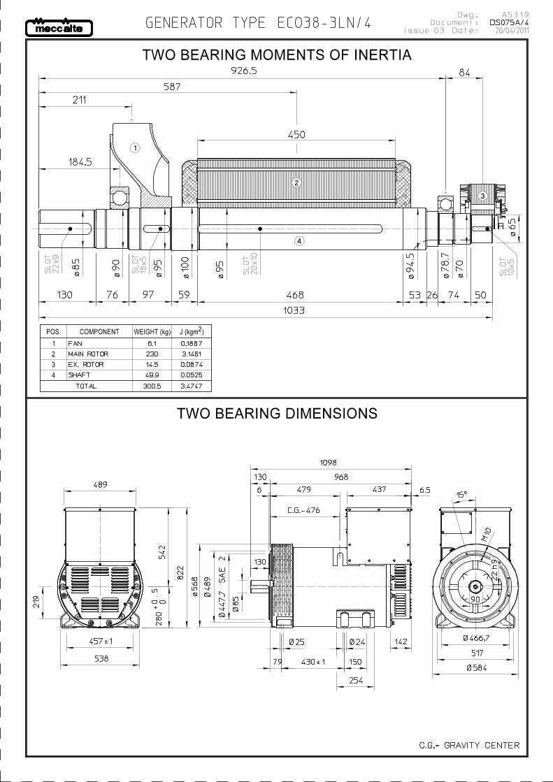
GENERATOR TYPE ECO 38-3LN/4 Document : DS075A/1issue 004 date 28/10/2013
Electrical CharacteristicsFrequency HzVoltage (series star) V 380 400 415 440 415 440 460 480
Rated power class H kVA 350 350 350 340 380 420 420 420
kW 280 280 280 272 304 336 336 336
Rated power class F kVA 320 320 320 310 350 385 385 385
kW 256 256 256 248 280 308 308 308
Regulation with DSRInsulation classExecution Stator windingRotorEfficiencies class H 4/4 % 93,4 93,5 93,2 93 93,6 94,1 94,2 94,3
(see graph. for details) 3/4 % 93,4 93,7 93,6 93,3 93,9 94,1 94,3 94,5
2/4 % 92,5 92,6 92,6 92,4 93 93,1 93,2 93,3
1/4 % 90,1 89,9 89,7 89,5 90,6 90,6 90,6 90,4
Reactances (f. l.cl. F) Xd % 238,2 215 199,7 172,6 260,2 255,9 234,1 215
Xd' % 19,1 17,2 16,0 13,8 20,8 20,5 18,7 17,2
Xd" % 10,4 9,4 8,7 7,5 11,4 11,2 10,2 9,4
Xq % 139,6 126 117,1 101,2 152,5 150,0 137,2 126
Xq' % 139,6 126 117,1 101,2 152,5 150,0 137,2 126
Xq" % 22,3 20,1 18,7 16,1 24,3 23,9 21,9 20,1X2 % 17,4 15,7 14,6 12,6 19,0 18,7 17,1 15,7X0 % 2,4 2,2 2,0 1,8 2,7 2,6 2,4 2,2
Short Circuit Ratio Kcc 0,37 0,42 0,57 0,92 0,24 0,32 0,37 0,42
Time Constants Td' sec.Td" sec.Tdo' sec.Tα sec.
Short Circuit Current Capacity %Excitation at no load Amp. 0,55 0,72 0,95 1,2 0,35 0,35 0,6 0,7
Excitation at full load Amp. 3,5 3,9 4,1 4,3 3,3 3,5 3,7 3,9
Overload (long-term) %Overload per 20 sec. %Stator Winding Resistance (20°C) ΩRotor Winding Resistance (20°C) ΩExciter Resistance (20 °C) Ω Rotor : 0,685 Stator : 15,28
Heat dissipation at f.l.cl.H W 19786 19465 20429 20473 20786 21067 20688 20310
Telephone Interference THF < 2% TIF < 40
Radio interferenceWaveform Distors.(THD) at f. load LL/LN % 3,1 / 2,9
Waveform Distors.(THD) at no load LL/LN % 2,7 / 2,7
Mechanical characteristicsProtection IP 21 (other protection on request )
DE bearing 6318.2RS
NDE bearing 6314.2RS
Weight of wound stator assembly kg 347
Weight of wound rotor assembly kg 230
Weight of complete generator kg 905
Maximun overspeed rpm 2250
Unbalanced magnetic pull at f.l.cl.F kN/mm 6,2
Cooling air requirement m³/min 32 39
Inertia Constant (H) sec. 0,123 0,147Noise level at 1m/7m dB(A) 82 / 69 86 / 73
This document is a propriety of Mecc Alte S.p.a..All rights reserved.
EN61000-6-3, EN61000-6-2. For others standards apply to factory
All technical data are to be considered as a reference and they can be modified without any notice.
50 60
±1 % with any power factor and speed variations between -5% +30%
H
Brushless
12 ends
with damping cage
0,099
0,0127
1,50
300
0,0042
6,780
0,013
>350>300
1 hour in a 6 hours period 110% rated load

Document : DS075A/2issue 004 date : 28/10/2013
This document is a propriety of Mecc Alte S.p.a.. All rights reserved.
GENERATOR TYPE ECO 38-3LN/4
50 Hz
88
89
90
91
92
93
94
95
96
97
0,1 0,2 0,3 0,4 0,5 0,6 0,7 0,8 0,9 1 1,1
Effi
cien
cy %
Load p.u.
380/50
0,8 p.f.
1 p.f.
88
89
90
91
92
93
94
95
96
97
0,1 0,2 0,3 0,4 0,5 0,6 0,7 0,8 0,9 1 1,1
Effi
cien
cy %
Load p.u.
1 p.f.
0,8 p.f.
400/50
88
89
90
91
92
93
94
95
96
97
0,1 0,2 0,3 0,4 0,5 0,6 0,7 0,8 0,9 1 1,1
Effi
cien
cy %
Load p.u.
1 p.f.
0,8 p.f.
87
88
89
90
91
92
93
94
95
96
0,1 0,2 0,3 0,4 0,5 0,6 0,7 0,8 0,9 1 1,1
Effi
cien
cy %
Load p.u.
1 p.f.
0,8 p.f.
0
10
20
30
40
0 1 2 3 4
Vol
tage
dip
%
380/50
Current p.u.
0,8 p.f.
1 p.f.
0 p.f.
0
10
20
30
40
0 1 2 3 4
Vol
tage
dip
%
Current p.u.
400/50
0 p.f.
0,8 p.f.
1 p.f.
0
10
20
30
40
0 1 2 3 4
Vol
tage
dip
%
Current p.u.
0 p.f.
0,8 p.f.
1 p.f.
415/50
440/50
415/50
0
10
20
30
0 1 2 3 4
Vol
tage
dip
%
Current p.u.
0 p.f.
0,8 p.f.
1 p.f.
10
100
1000
10000
100000
0,001 0,01 0,1 1 10
Am
pere
s
Three phase short circuit decrement curve. No load excitation at rated speed
Seconds
Asymmetrical
Symmetrical
440/50
Document : DS075A/3issue 004 date : 28/10/2013
This document is a propriety of Mecc Alte S.p.a.. All rights reserved.
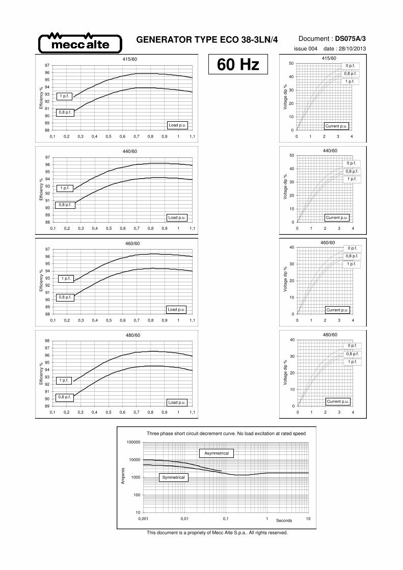
GENERATOR TYPE ECO 38-3LN/4
60 Hz
88
89
90
91
92
93
94
95
96
97
0,1 0,2 0,3 0,4 0,5 0,6 0,7 0,8 0,9 1 1,1
Effi
cien
cy %
Load p.u.
415/60
0,8 p.f.
1 p.f.
88
89
90
91
92
93
94
95
96
97
0,1 0,2 0,3 0,4 0,5 0,6 0,7 0,8 0,9 1 1,1
Effi
cien
cy %
Load p.u.
1 p.f.
0,8 p.f.
440/60
88
89
90
91
92
93
94
95
96
97
0,1 0,2 0,3 0,4 0,5 0,6 0,7 0,8 0,9 1 1,1
Effi
cien
cy %
Load p.u.
1 p.f.
0,8 p.f.
89
90
91
92
93
94
95
96
97
98
0,1 0,2 0,3 0,4 0,5 0,6 0,7 0,8 0,9 1 1,1
Effi
cien
cy %
Load p.u.
1 p.f.
0,8 p.f.
0
10
20
30
40
50
0 1 2 3 4
Vol
tage
dip
%
415/60
Current p.u.
0,8 p.f.
1 p.f.
0 p.f.
0
10
20
30
40
50
0 1 2 3 4
Vol
tage
dip
%
Current p.u.
440/60
0 p.f.
0,8 p.f.
1 p.f.
0
10
20
30
40
0 1 2 3 4
Vol
tage
dip
%
Current p.u.
0 p.f.
0,8 p.f.
1 p.f.
460/60
480/60
460/60
0
10
20
30
40
0 1 2 3 4
Vol
tage
dip
%
Current p.u.
0 p.f.
0,8 p.f.
1 p.f.
10
100
1000
10000
100000
0,001 0,01 0,1 1 10
Am
pere
s
Three phase short circuit decrement curve. No load excitation at rated speed
Seconds
Asymmetrical
Symmetrical
480/60