Embed Size (px)
Citation preview
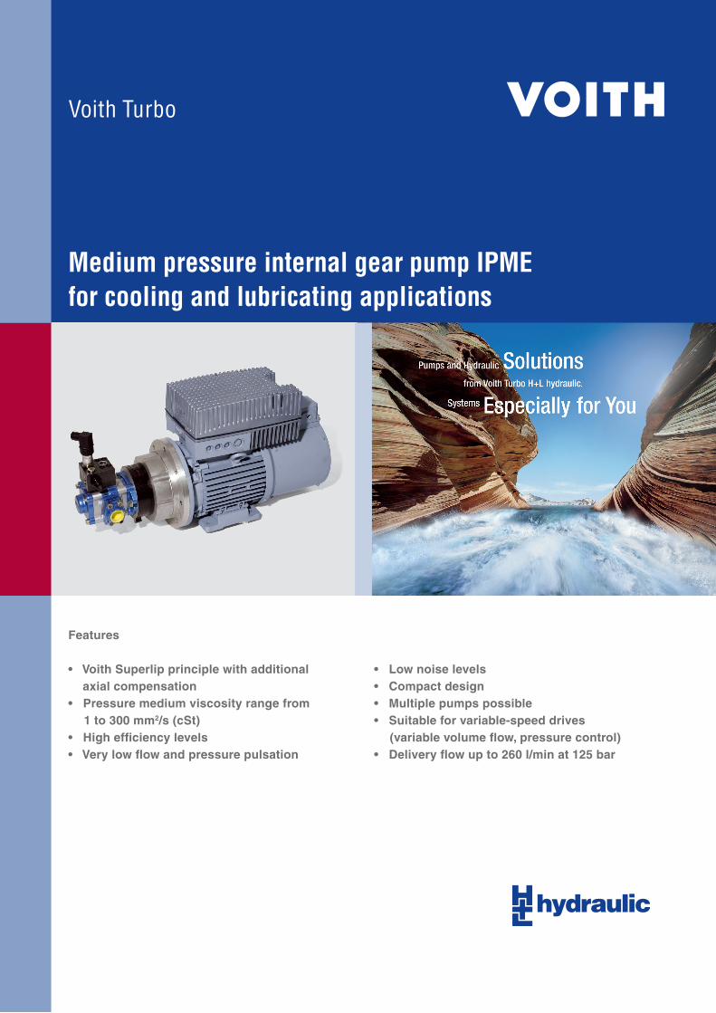
Medium pressure internal gear pump IPMEfor cooling and lubricating applications
Features
• Voith Superlip principle with additional axial compensation• Pressure medium viscosity range from 1 to 300 mm2/s (cSt)• High efficiency levels• Very low flow and pressure pulsation
• Low noise levels• Compact design• Multiple pumps possible• Suitable for variable-speed drives (variable volume flow, pressure control)• Delivery flow up to 260 l/min at 125 bar

Voith Turbo H + L Hydraulic | Page IP101-0� | Revision 1107 en
�
Characteristic data ..........................................................................................................................................3
Design options .................................................................................................................................................3
Technical data ..................................................................................................................................................4
Operational characteristics IPME 4 standard design ...................................................................................5
Dimensional drawing IPME 4 standard design .............................................................................................6
Operational characteristics IPME 5 standard design ...................................................................................7
Dimensional drawing IPME 5 standard design .............................................................................................8
Operational characteristics IPME 6 standard design ...................................................................................9
Dimensional drawing IPME 6 standard design ...........................................................................................10
Multiple combinations for greater displacement volumes ........................................................................11
Possible pump combinations .......................................................................................................................12
Dimensions for calculating total length of pump combinations ...............................................................12
EPA − electric motor pump set .....................................................................................................................13
Type code EPA ...............................................................................................................................................14
EPA(F) − Electric motor pump set with variable flow .................................................................................15
Type code EPAF .............................................................................................................................................16
Standard value EPA(F) ..................................................................................................................................17
Design example EPAF 5,5-4-V1-XLF-ME4-13-L1 .........................................................................................21
Components for pressure control................................................................................................................22
Table of contents

Voith Turbo H + L Hydraulic | Page IP101-0� | Revision 1107 en
Standard TypeSize
Displacement volume*
Revolution speed Delivered flow**Continuous
pressureWeight
(pmax) min max n = 1450 1/min
n = nmax .10cSt <10cSt
cm�/U 1/min 1/min l/min l/min bar bar kg
IPME 4 1� 400 �600 19,1 47,4 100 1�5 5,5
IPME 5 �5 400 �000 �6,6 75,7 100 1�5 9,8
IPME 6 50 400 �600 7�,0 1�0,9 100 1�5 16,5
Design options
* Due to manufacturing tolerances the displacement volume can be lower around 1,5%
** Delivered flow without consideration of the volumetric efficiency
I P M E G 4 - 1 � 1 0 1
Shaft extension1 = key
Fastening flange0 = SAE � hole4 = ISO � hole
Direction of rotation (view of pump shaft)1 = right6 = left
Displacement volume
Size
Shaft sealwithout designation = Varilip (standard)G = mechanical seal
�
Characteristic data

Voith Turbo H + L Hydraulic | Page IP101-04 | Revision 1107 en
General
Type of construction internal gear pump without filler element with radial gap compen-sation (Voith Superlip principle)
Fastening possibilities ISO or SAE � hole flange with key shaft
Direction of rotation right or left rotation
Drive power see the following data sheets
Shaft load for radial and/or axial load of the drive shaft please consult us
Installation position any position
Flow medium coolants and lubricants (emulsions and oils), cutting oil, special fluids on request
Ambient temperature °C -10 to +60
Contamination level max. admissible contamination level of the pressurized fluid 40 mg/l and particle size < �0 μm. This corresponds to NAS 16�8 class 11 with steel and class 1� with aluminum.
Hydraulic characteristics
Input pressure bar 0,8 to �,0 bar (abs.) max. 6,0 bar (abs.) with mechanical seal
Continuous pressure bar see table characteristic data
Flow medium temperature °C 0 to +80
Viscosity range mm�/s 1 to �00; admissible start up viscosity: �000
Technical data
4
Voith Turbo H + L Hydraulic | Page IP101-05 | Revision 1107 en
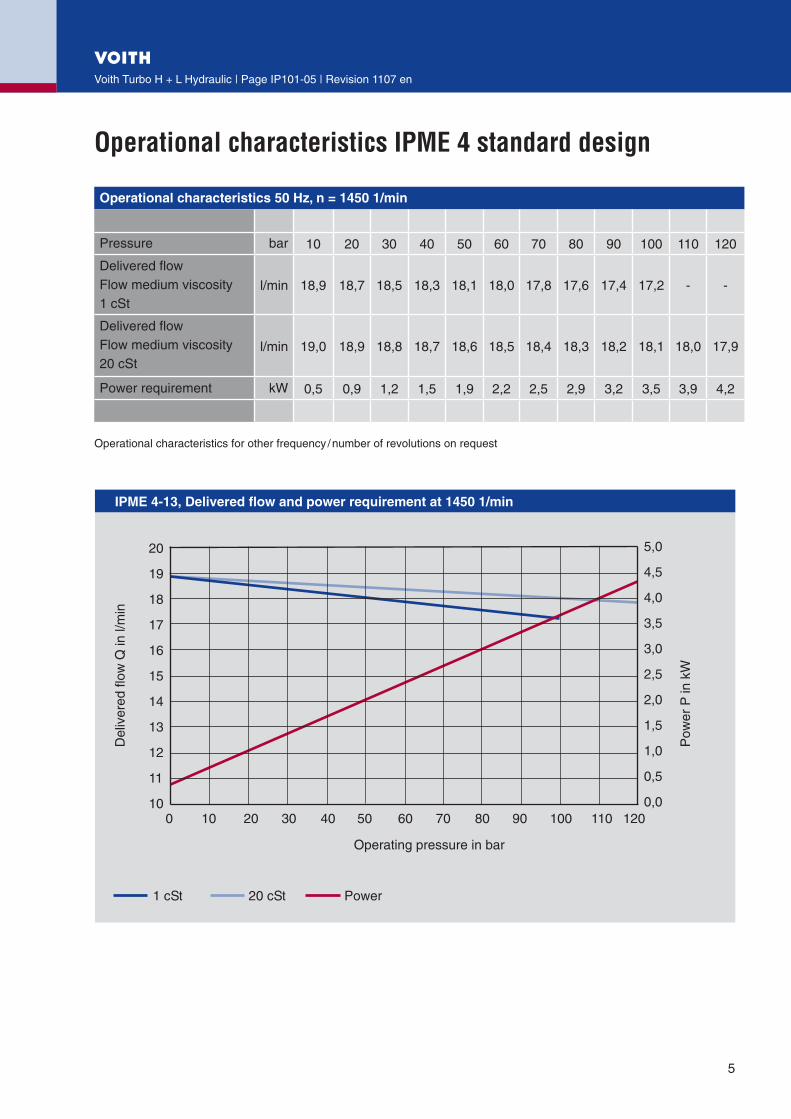
Operational characteristics IPME 4 standard design
Operational characteristics 50 Hz, n = 1450 1/min
Pressure bar 10 �0 �0 40 50 60 70 80 90 100 110 1�0
Delivered flow Flow medium viscosity 1 cSt
l/min 18,9 18,7 18,5 18,� 18,1 18,0 17,8 17,6 17,4 17,� - -
Delivered flow Flow medium viscosity �0 cSt
l/min 19,0 18,9 18,8 18,7 18,6 18,5 18,4 18,� 18,� 18,1 18,0 17,9
Power requirement kW 0,5 0,9 1,� 1,5 1,9 �,� �,5 �,9 �,� �,5 �,9 4,�
Operational characteristics for other frequency / number of revolutions on request
5
��
��
��
��
��
��
��
��
��
��
��
���
���
���
���
���
���
���
���
���
���
���� �� �� �� �� �� �� �� �� �� ��� ��� ���
�������������������������������������������������������������
�������
�������
�����
����
��
�������������������������
���
����
������
����� ������ �����
Voith Turbo H + L Hydraulic | Page IP101-06 | Revision 1107 en
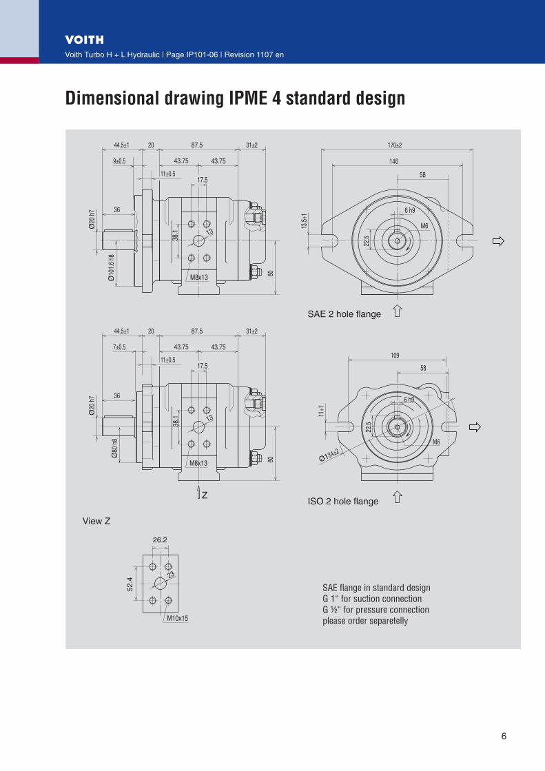
Dimensional drawing IPME 4 standard design
6
���
���
���
���
������
�
����
����
��
������
������������������������������������������������������������������������������������������������������������
�����������������
�����������������
�����
��
�����
��
���
�������
�
�����
����
���
����
���
����
�
����
��
����
����� �����
����
����
��������
��
�����
������
��
��
���
������
����
����
����
����
����
����� �����
����
����
��������
��
�����
������
��
���� ��

Voith Turbo H + L Hydraulic | Page IP101-07 | Revision 1107 en
Operational characteristics IPME 5 standard design
Operational characteristics 50 Hz, n = 1450 1/min
Pressure bar 10 �0 �0 40 50 60 70 80 90 100 110 1�0
Delivered flow Flow medium viscosity 1 cSt
l/min �6,� �5,9 �5,5 �5,� �4,8 �4,4 �4,1 ��,7 ��,� ��,0 - -
Delivered flow Flow medium viscosity �0 cSt
l/min �6,4 �6,� �6,0 �5,9 �5,7 �5,5 �5,� �5,1 �4,9 �4,7 �4,5 �4,4
Power requirement kW 1,� 1,8 �,4 �,1 �,7 4,4 5,0 5,6 6,� 6,9 7,6 8,�
Operational characteristics for other frequency / number of revolutions on request
7
��
��
��
��
��
��
��
��
��
��
��
��
�
�
�
�
�
�
�
�
�
�� �� �� �� �� �� �� �� �� �� ��� ��� ���
�������������������������������������������������������������
�������
�������
�����
����
��
�������������������������
���
����
������
����� ������ �����
Voith Turbo H + L Hydraulic | Page IP101-08 | Revision 1107 en
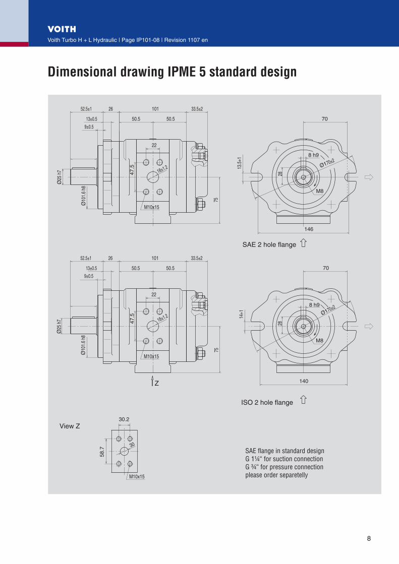
Dimensional drawing IPME 5 standard design
8
����
��
��
���
����
��
��
���
����
����
����
����
��
������
�
������
�������������������������������������������������������������������������������������������������������������
�����������������
�����������������
���
����
��
������
���� ����
�����������
�����������
��
������
������
������
������
��
����
��
����
����
���
���
���
����
��
������
���� ����
�����������
�����������
��
������
������
��
���
���

Voith Turbo H + L Hydraulic | Page IP101-09 | Revision 1107 en
Operational characteristics IPME 6 standard design
Operational characteristics 50 Hz, n = 1450 1/min
Pressure bar 10 �0 �0 40 50 60 70 80 90 100 110 1�0
Delivered flow Flow medium viscosity 1 cSt
l/min 7�,� 71,6 70,8 70,1 69,4 68,7 67,8 67,� 66,5 65,8 - -
Delivered flow Flow medium viscosity �0 cSt
l/min 7�,6 7�,� 71,9 71,6 71,� 70,8 70,5 70,1 69,7 69,4 69,0 68,7
Power requirement kW �,1 �,4 4,7 5,9 7,� 8,5 9,8 11,1 1�,4 1�,6 14,9 16,4
Operational characteristics for other frequency / number of revolutions on request
9
��
��
��
��
��
��
��
��
��
��
��
��
��
��
��
��
��
�
�
�
�
�� �� �� �� �� �� �� �� �� �� ��� ��� ���
�������������������������������������������������������������
�������
�������
�����
����
��
�������������������������
���
����
������
����� ������ �����

Voith Turbo H + L Hydraulic | Page IP101-010 | Revision 1107 en
Dimensional drawing IPME 6 standard design
10
�����
���
��
���
�����������������
�����
���
���
��
�����������������
������
���
����
��
�
���
����
����
����� �����
�������������
�����
��
������ ��
���
���
����
���� ����
��
��
��
������
�������������������������������������������������������������������������������������������������������������
��
������
���
����
����
����� �����
�������������
�����
��
������
������
��
���
���
����
����
������
���
����
��
Voith Turbo H + L Hydraulic | Page IP101-011 | Revision 1107 en
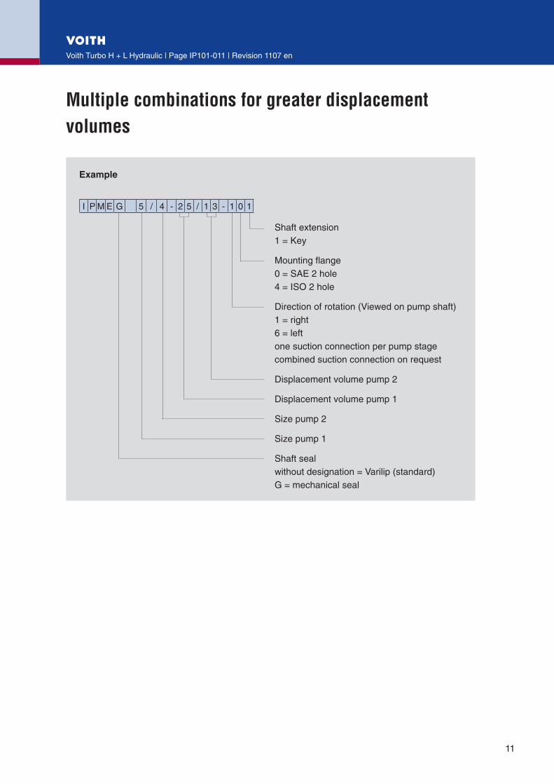
Multiple combinations for greater displacement volumes
I P M E G 5 / 4 - � 5 / 1 � - 1 0 1
Shaft extension1 = Key
Mounting flange0 = SAE � hole4 = ISO � hole
Direction of rotation (Viewed on pump shaft)1 = right6 = leftone suction connection per pump stagecombined suction connection on request
Displacement volume pump �
Displacement volume pump 1
Size pump �
Size pump 1
Shaft sealwithout designation = Varilip (standard)G = mechanical seal
11
Example

Voith Turbo H + L Hydraulic | Page IP101-01� | Revision 1107 en
Possible pump combinations
Pump 2
IPME 4-1� IPME 5-�5 IPME 6-50
Pu
mp
1
IPME 4-1� IPME 4/4-1�/1� - -
IPME 5-�5 IPME 5/4-�5/1� IPME 5/5-�5/�5 -
IPME 6-50 IPME 6/4-50/1� IPME 6/5-50/�5 IPME 6/6-50/50
Requiered intermediate housing
IPME 4-1� ��5 - -
IPME 5-�5 ��6 ��7 -
IPME 6-50 ��8 ��9 ��0
Flange thickness “a” primary pumpLength of housing “c”primary pumpLength dimension “m / o” intermediate housingLength of pump housing “d” B-stage End cover “e” of the B-stage
Detail dimensions see single pump
The example shows a combination of two pumps.Combination of three pumps on request.
Dimensions for calculating total length of pump combinations
�� � � �
a c m d e
IPME 4/4-1�/1� �0 87,5 48 87,5 �1
IPME 5/4-�5/1� �6 101 54 87,5 �1
IPME 5/5-�5/�5 �6 101 6� 101 ��,5
IPME 6/4-50/1� �4 1�7,5 6� 87,5 �1
IPME 6/5-50/�5 �4 1�7,5 66 101 ��,5
IPME 6/6-50/50 �4 1�7,5 67 1�7,5 40
1�

Voith Turbo H + L Hydraulic | Page IP101-01� | Revision 1107 en
EPA − electric motor pump set
Parameter of the normated motors DIN 42677 at 50 Hz, 1450 min-1
Size PowerVoith Code
Pump type
Total delivered flow at continuous pressure
Continuous pressure max.
.10 cSt <10 cSt 1 cSt �0 cSt
kW l/min l/min bar bar
90 S 1,1 1,1 IPME 4 18,6 18,9 �5
90 L 1,5 1,5 IPME 4 18,� 18,7 40
100 L �,� �,� IPME 4 18,0 18,5 60
100 L�,0 �,0
IPME 4 17,6 18,� 80
IPME 5 �5,� �4,8 50
11� M 4,0 4,0IPME 4 17,� 18,0 100 110
IPME 5 �4,6 �5,6 55
IPME 5/4 5�,7 54,7 �0
1�� S 5,5 5,5IPME 4 17,9 1�0
IPME 5 ��,7 �5,1 80
IPME 5/4 5�,8 54,� 50
1�� M 7,5 7,5
IPME 5 ��,0 �4,5 100 110
IPME 5/4 51,8 5�,7 70
IPME 6 69,� 71,0 55
IPME 6/4 88,4 90,� 40
IPME 6/5 88,4 90,� 40
160 M 11 011
IPME 5 �4,4 1�0
IPME 5/4 50,� 5�,8 100 110
IPME 6 67,� 70,1 80
IPME 6/4 86,6 89,� 60
IPME 6/5 86,6 89,� 60
IPME 6/6 140,7 14�,� �5
160 L 15 015
IPME 5/4 5�,� 1�0
IPME 6 65,8 69,0 100 110
IPME 6/4 84,� 88,� 85
IPME 6/5 10�,0 105,0 70
IPME 6/6 1�9,0 14�,6 50
180M 18,5 018
IPME 6 68,7 1�0
IPME 6/4 8�,9 87,� 100 105
IPME 6/5 100,0 105,0 85
IPME 6/6 1�9,0 14�,6 65
180 L ��0��
IPME 6/4 86,6 1�0
IPME 6/5 100,0 105,0 85
IPME 6/6 1�4,4 140,� 80
�00 L�0 0�0
IPME 6/5 10�,0 1�0
IPME 6/6 1�1,5 1�8,0 100 110
��5 S IPME 6/6 1�7,� 1�0
Other power, frequency and number of revolutions on request 1�

Type code EPA
Voith Turbo H + L Hydraulic | Page IP101-014 | Revision 1107 en
E P A - 0 1 8 - 4 - V 1 - L L E - M E 6 - 5 0 - L 1
Direction pressure connection1 = Direction terminal box� = 90° to terminal box� = opposite terminal box4 = �70° to terminal box
Direction of rotation pump(seen on pump shaft)L = leftR = right
Pump according to type code page � page 11 for double pumps respectively
CoolingE = self-ventilatedF = force-ventilated
Direction cable connectionL = leftR = right
Direction terminal boxL = leftR = rightO = topside
Mounting formV1 = diving designB�5 = pedestal design
Number of poles
Rated power according to Voith Code Page 1�
Electric motor pump set
14

EPA(F) − Electric motor pump set with variable flow
Voith Turbo H + L Hydraulic | Page IP101-015 | Revision 1107 en
15
With the help of an additional frequency converter the described electric motor pump units can be operated at variable speed and thus variable deli-very. It is possible to use the entire operating range of the electric motor under the motor control given deliveries and/or operating pressures without valve technology.Two modes of operation are possible:
1. Flow controlThe necessary cooling agent quantities are given by machine control. The operating pressure places itself according to the resistances (piping etc.) in the
system and dependent on the available torque ac-cording to the motor characteristic. Individual pressu-re phases and maximum pressure must be secured separately with pressure control valves.
2. Pressure controlThe necessary cooling agent pressures are given by machine control. The motor speed is reduced accor-ding to the motor characteristic, and/or regulated by frequency changer so that the pressure is held. Pres-sure control valves for individual pressure phases are not required, a maximum pressure protection is only needed.
���������������������������������������������������������
���������������������
��������������������������������������������������
����� �����
�����������������
�����������������
�����������������
����
������
����
����
�����
�
Reference values for the operating points A, B and C see tables on the pages 17 to �0.

Type code EPAF
Voith Turbo H + L Hydraulic | Page IP101-016 | Revision 1107 en
E P A F - 4, 0 - 4 - V 1 - X L E - M E 6 - 5 0 - L 1
Direction pressure connection1 = Direction terminal box� = 90° to terminal box� = opposite terminal box4 = �70° to terminal box
Direction of rotation pump(seen on pump shaft)L = leftR = right
Pump according to type code page � and page 10 for double pumps respectively
CoolingE = self-ventilatedF = force-ventilated
Direction cable connectionL = leftR = right
Direction terminal boxL = leftR = rightO = topsideX = replaced by frequency converter
Mounting formV1 = diving designB�5 = pedestal design
number of poles
Rated power according to Voith Code Page 1�
Frequency converter fitted direct on elec-tric motor (only up to 7,5 kW possible)
Electric motor pump power pack
16

Standard value EPA(F)
Voith Turbo H + L Hydraulic | Page IP101-017 | Revision 1107 en
EPA-XXX-4-V1-XLE-ME4-13-L1
IPME 4-1�, Vg=1� cm�
nominalelectric motor
speed
voltage factor0,95
operating point A operating point Bn = ca. �000 1/min
operating point Cn = ca. �000 1/min
p Q p Q p Q
kW 1/min 1/min bar l/min bar l/min bar l/min
1,5 1�80 1�11 �6 16 �4 �5 11 �8
�,� 1410 1�40 57 16 �8 �5 17 �7
�,0 1410 1�40 8� 16 55 �4 �4 �6
4,0 14�0 1�49 11� 16 76 �� �4 �5
5,5 14�0 1�59 *158 15 107 �� 48 ��
EPA-XXX-4-V1-XLE-ME5-25-L1
IPME 5-�5, Vg=�5 cm�
nominalelectric motor
speed
voltage factor0,95
operating point A operating point Bn = ca. �000 1/min
operating point Cn = ca. �000 1/min
p Q p Q p Q
kW 1/min 1/min bar l/min bar l/min bar l/min
�,0 1410 1�40 �7 �� �5 48 11 7�
4,0 14�0 1�49 5� �� �6 48 16 71
5,5 14�0 1�59 77 �� 5� 46 �� 70
7,5 14�0 1�59 109 �1 74 45 �� 68
11,0 1465 1�9� *161 �0 11� 4� 50 64
17
*Attention: Please be aware of the admissible continuous pump pressure!

Standard value EPA(F)
Voith Turbo H + L Hydraulic | Page IP101-018 | Revision 1107 en
EPA-XXX-4-V1-XLE-ME6-50-L1
IPME 6-50, Vg=50 cm�
nominalelectric motor
speed
voltage factor0,95
operating point A operating point Bn = ca. �000 1/min
operating point Cn = ca. �600 1/min
p Q p Q p Q
kW 1/min 1/min bar l/min bar l/min bar l/min
5,5 14�0 1�59 �� 66 �� 98 1� 1�7
7,5 14�0 1�59 48 66 �� 97 19 1�6
11,0 1465 1�9� 74 66 5� 95 �1 1��
15,0 1465 1�9� 106 65 74 9� 4� 1�1
18,5 1470 1�97 1��* 64 9� 91 55 118
EPA-XXX-4-V1-XLE-ME5/4-25/13-L1
IPME 5/4-�5/1�, Vg=�8 cm�
nominalelectric motor
speed
voltage factor0,95
operating point A operating point Bn = ca. �000 1/min
operating point Cn = ca. �000 1/min
p Q p Q p Q
kW 1/min 1/min bar l/min bar l/min bar l/min
4,0 14�0 1�49 �1 50 �1 74 9 111
5,5 14�0 1�59 46 49 �1 7� 14 109
7,5 14�0 1�59 67 48 46 71 �0 107
11,0 1465 1�9� 10� 48 71 69 �1 104
15,0 1465 1�9� 14�* 46 99 66 44 99
18
*Attention: Please be aware of the admissible continuous pump pressure!
Standard value EPA(F)
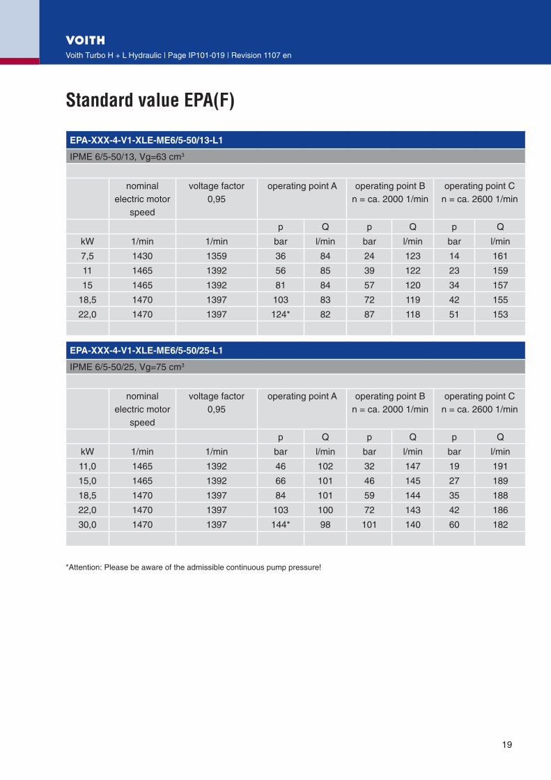
Voith Turbo H + L Hydraulic | Page IP101-019 | Revision 1107 en
EPA-XXX-4-V1-XLE-ME6/5-50/13-L1
IPME 6/5-50/1�, Vg=6� cm�
nominalelectric motor
speed
voltage factor0,95
operating point A operating point Bn = ca. �000 1/min
operating point Cn = ca. �600 1/min
p Q p Q p Q
kW 1/min 1/min bar l/min bar l/min bar l/min
7,5 14�0 1�59 �6 84 �4 1�� 14 161
11 1465 1�9� 56 85 �9 1�� �� 159
15 1465 1�9� 81 84 57 1�0 �4 157
18,5 1470 1�97 10� 8� 7� 119 4� 155
��,0 1470 1�97 1�4* 8� 87 118 51 15�
EPA-XXX-4-V1-XLE-ME6/5-50/25-L1
IPME 6/5-50/�5, Vg=75 cm�
nominalelectric motor
speed
voltage factor0,95
operating point A operating point Bn = ca. �000 1/min
operating point Cn = ca. �600 1/min
p Q p Q p Q
kW 1/min 1/min bar l/min bar l/min bar l/min
11,0 1465 1�9� 46 10� �� 147 19 191
15,0 1465 1�9� 66 101 46 145 �7 189
18,5 1470 1�97 84 101 59 144 �5 188
��,0 1470 1�97 10� 100 7� 14� 4� 186
�0,0 1470 1�97 144* 98 101 140 60 18�
19
*Attention: Please be aware of the admissible continuous pump pressure!

Standard value EPA(F)
Voith Turbo H + L Hydraulic | Page IP101-0�0 | Revision 1107 en
EPA-XXX-4-V1-XLE-ME6/6-50/50-L1
IPME 6/6-50/50, Vg=100 cm�
nominalelectric motor
speed
voltage factor0,95
operating point A operating point Bn = ca. �000 1/min
operating point Cn = ca. �600 1/min
p Q p Q p Q
kW 1/min 1/min bar l/min bar l/min bar l/min
11,0 14�0 1�59 �� 1�4 �� 198 1� �57
15,0 1465 1�9� 47 1�7 �� 197 19 �56
18,5 1465 1�9� 61 1�6 4� 196 �5 �55
��,0 1470 1�97 74 1�6 5� 195 �1 �5�
�0,0 1470 1�97 105 1�5 7� 19� 4� �51
�7,0 1470 1�97 1��* 1�� 9� 191 55 �48
�0
*Attention: Please be aware of the admissible continuous pump pressure!

Design example EPAF 5,5-4-V1-XLF-ME4-13-L1
Voith Turbo H + L Hydraulic | Page IP101-0�1 | Revision 1107 en
�1
The direct construction of the frequency static fre-quency convertor on the electric motor is possible for electric motors from 1,1 kW to 7,5 kW. For this
and higher power also separate frequency static frequency convertor for control cabinet installation are available.
��
���
�
����
���
�
����
��
����
������
��������������
���
��� ���
����
���������������
����
���
�����
��
��
������������
���

Components for pressure control
Voith Turbo H + L Hydraulic | Page IP101-0�� | Revision 1107 en
Pressure control valves for cooling and lubricating applications
Pipe connection - see separate data sheetFlange design for direct mounting on the pump - see separate data sheet
��
������������������
����������������������������
����������������������
������������������������������������������
��������������������������������
��� �������������������������������������������������������� ������������������������������������������
�����������������������������
��
�

Voith Turbo H + L Hydraulic GmbH & Co. KG
Schuckertstraße 15
71�77 Rutesheim, Germany
Tel. +49 (0)715� / 99�-�
Fax +49 (0)715� / 99�-400
www.voithturbo.com
VT
HL
IP10
1 en
, MB
i, 11
/07.
Dim
ensi
ons
and
illus
trat
ions
with
out o
blig
atio
n. S
ubje
ct to
mod
ifcat
ions
.