Embed Size (px)
Citation preview

Military Product Catalog

Field Tested... Proven Reliability
Partial Listing: F-16
F/A-18
F-22
P-3 Orion
Tornado
AWACS
J-STARS
V-22 Osprey
Eurofighter Typhoon
Predator UAV
E-2C Hawkeye
Nimrod MRA4
EA-6B Prowler
Bradley M2/M3
Harpoon Missile
Tow Missile
Tomahawk Cruise Missile
Patriot Missile Launcher
THAAD Missile Launcher
MLRS Missile Launcher
NASA Space Shuttle
International Space Station
Secure Communications Equipment
Digital Displays
Fire Control Systems
Mine Hunting Sonar
Electronic Warfare
Radar Jamming Systems
Vicor’s military products have been and continue to be selected for use in a wide variety
of strategic military and aerospace applications.

4
6
Table of Contents
2
3
28
30
32
34
35
368
14
16
18
20
24
12
Accessories
Environmental Stress ScrScreening & MTBFeening & MTBFDescription of the post-production module screening.Includes examples of calculated MTBF
Environmental QualificationProduct qualification to MIL-STD-810 and MIL-STD-202
Custom PowerVicor Integration Architects (VIAs) and International Value Added Resellers (VARs) offer turnkey custom power systems
Custom Configured ModulesWeb-based computer aided configuration of semi-custom 2nd Generation converters
Technical SupportWorldwide contacts for customer service and applications support
19
Military StandardsProduct compliance with military standards
Product OverviewSummary presentation of military product line
Military Data Sheets
MI-20050 to 100W, high-densityDC-DC converters
MI-J0010 to 50W, high-densityDC-DC converters
24/28V, 48V, 270/300V/300V,, 375V375VUp to 600W, high-density 2nd Generation DC-DC converters
MI-IAMEMI/RFI filtering and transient protectionmodule for 28Vdc and 270Vdc systems
M-FIAM3 & M-FIAM52nd Generation input filter and transient suppression module
MI-AIMAC front end module115Vac input, 250W output
MI-RAMOutput ripple attenuator modules
MicroRAMOutput ripple attenuator modules
MI-MegaMod10 to 300W chassis mountDC-DC converters
MI-ComPACComplete single, dual, or tripleoutput DC-DC power supply
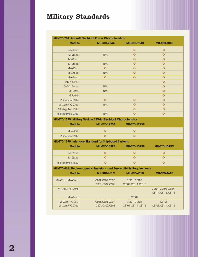
Military Standards
MI-J2x-xx
MI-J6x-xx N/A
MI-22x-xx
MI-26x-xx N/A
MI-A22-xx
MI-A66-xx N/A
MI-AIM-xx
24Vin Series
300Vin Series N/A
M-FIAM3 N/A
M-FIAM5
MI-ComPAC 28V
MI-ComPAC 270V N/A
MI-MegaMod 28V
MI-MegaMod 270V N/A
MI-A22-xx
MI-ComPAC 28V
MI-J5x-xx
MI-25x-xx
MI-MegaMod 155V
MI-A22-xx, MI-A66-xx CE01, CE03, CE07, CE101, CE102,
CS01, CS02, CS06 CS101, CS114, CS116
M-FIAM3, M-FIAM5 CE101, CE102, CS101,
CS114, CS115, CS116
MI-AIM-xx CE102
MI-ComPAC 28V, CE01, CE03, CE07, CE101, CE102, CE101
MI-ComPAC 270V CS01, CS02, CS06 CS101, CS114, CS116 CS101, CS114, CS116
MIL-STD-704: Aircraft Electrical Power Characteristics
Module MIL-STD-704A MIL-STD-704D MIL-STD-704E
MIL-STD-1275: Military Vehicle 28Vdc Electrical Characteristics
Module MIL-STD-1275A MIL-STD-1275B
MIL-STD-1399: Interface Standard for Shipboard Systems
Module MIL-STD-1399A MIL-STD-1399B MIL-STD-1399C
MIL-STD-461: Electromagnetic Emissions and Susceptibility Requirements
Module MIL-STD-461C MIL-STD-461D MIL-STD-461E
2
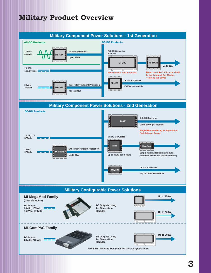
Military Configurable Power Solutions
Up to 300W
MI-MegaMod Family(Chassis Mount)
Up to 300W
MI-ComPAC Family
1-3 Outputs using1st Generation Modules
Front End Filtering Designed for Military Applications
1-3 Outputs using1st Generation Modules
DC Inputs28Vdc, 155Vdc, 165Vdc, 270Vdc
DC Inputs28Vdc, 270Vdc
Up to 150W
115Vac60/400Hz
28, 155,165, 270Vdc
Rectifier/EMI Filter
Up to 250WMI-AIM
MI-IAM
MI-200
MI-J00
MI-RAM
More Power? Add a Booster. Ultra Low Noise? Add an MI-RAMto the Output of Any Module.<3mV pp at 5-50Vdc
10-50W per module
Up to 20A
DC-DC Converter50-100W
DC-DC Converter
AC-DC Products
Military Component Power Solutions - 1st Generation
EMI Filter/Transient Protection
Up to 200W
DC-DC Products
Up to 600W per module
M-FIAMUp to 20A
MAXIDC-DC Converter
MINI
DC-DC Converter
Up to 300W per module
DC-DC Converter
Up to 150W per module
MICRO
Single Wire Paralleling for High Power, Fault Tolerant Arrays
EMI Filter/Transient Protection
Military Component Power Solutions - 2nd GenerationDC-DC Products
28Vdc, 270Vdc
28Vdc, 270Vdc
28, 48, 270, 375Vdc
MicroRAM
Output ripple attenuation module combines active and passive filtering
Military Product Overview
3
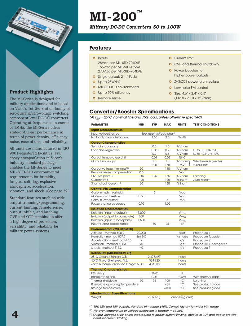
Product HighlightsThe MI-Series is designed for
military applications and is based
on Vicor’s 1st Generation family of
zero-current/zero-voltage switching,
component level DC-DC converters.
Operating at frequencies in excess
of 1MHz, the MI-Series offers
state-of-the-art performance in
terms of power density, efficiency,
noise, ease of use, and reliability.
All units are manufactured in ISO
9001-registered facilities. Full
epoxy encapsulation in Vicor’s
industry standard package
enables the MI-Series to meet
MIL-STD-810 environmental
requirements for humidity,
fungus, salt, fog, explosive
atmosphere, acceleration,
vibration, and shock. (See page 32.)
Standard features such as wide
output trimming/programming,
current limiting, remote sense,
output inhibit, and latching
OVP and OTP combine to offer
a high degree of protection,
versatility, and reliability for
military power systems.
MI-200TM
PARAMETER MIN TYP MAX UNITS TEST CONDITIONS
Input CharacteristicsInput voltage range See input voltage chartNo load power dissipation 1.35 2.0 Watts
Output CharacteristicsSet point accuracy 0.5 1.0 % VnomLoad/line regulation 0.05 0.2 % Vnom LL to HL, 10% to FL
0.2 0.5 % Vnom LL to HL, NL to 10%Output temperature drift 0.01 0.02 %/°COutput noise - pp 1.0 1.5 % Vnom Whichever is greater
100 150 mV 20MHz BWOutput voltage trimming(1) 50 110 % VnomRemote sense compensation 0.5 VdcOVP set point (2) 115 125 135 % Vnom LatchingCurrent limit 105 125 % Inom Auto restartShort circuit current (3) 20 130 % Inom
Control Pin CharacteristicsGate-in high threshold 6 VdcGate-in low threshold 0.65 VdcGate-in low current 6 mAPower sharing accuracy 0.95 1.05
Isolation CharacteristicsIsolation (input to output) 3,000 VrmsIsolation (output to baseplate) 500 VrmsIsolation (input to baseplate) 1,500 VrmsInput/output capacitance 50 75 pF
Environmental (MIL-STD-810)Altitude - method 500.2 70,000 feet Procedure IIHumidity - method 507.2 86/240 %/hours Procedure 1, cycle 1Acceleration - method 513.3 9 g's Procedure 2Vibration - method 514.3 20 g's Procedure 1, category 6Shock - method 516.3 40 g's Procedure 1
Reliability (MIL-HDBK-217F)25°C Ground Benign: G.B. 2,478,477 hours50°C Naval Sheltered: N.S. 584,920 hours65°C Airborne Inhabited Cargo: A.I.C. 483,303 hours
Thermal CharacteristicsEfficiency 80-90 %Baseplate to sink 0.07 °C/W With thermal padsThermal shutdown 90 95 105 °C LatchingBaseplate operating temperature +85 °C See product grade Storage temperature +100 °C See product grade
Mechanical SpecificationsWeight 6.0 (170) ounces (grams)
Converter/Booster Specifications(At TBP = 25°C, nominal line and 75% load, unless otherwise specified)
Features
Military DC-DC Converters 50 to 100W
(1) 10V, 12V, and 15V outputs, standard trim range ±10%. Consult factory for wider trim range.(2) No over temperature or voltage protection in booster modules.(3) Output voltages of 5V or less incorporate foldback current limiting; outputs of 10V and above provide
constant current limiting.4
Inputs:28Vdc per MIL-STD-704D/E155Vdc per MIL-STD-1399A270Vdc per MIL-STD-704D/E
Single output: 2 – 48Vdc
Up to 23W/in3
MIL-STD-810 environments
Up to 90% efficiency
Remote sense
Current limit
OVP and thermal shutdown
Power boosters for
higher power outputs
ZVS/ZCS power architecture
Low noise FM control
Size: 4.6" x 2.4" x 0.5"(116,8 x 61,0 x 12,7mm)

Configuration Chart
Input VoltageNominal Range Transient2 = 28V 18 – 50V
(1)60V
5 = 155V 100 – 210V 230V6 = 270V 125 – 400V
(2)475V
7 = 165V 100 – 310V
MI - 2 -Semi-custom driver and boostermodules available: Consult factory.
(1) 16V operation at 75% load.
(2) These units rated at 75% load from 125-150Vin:
MI-26Z-xVMI-26Y-xVMI-260-xW
28Vdc input per MIL-STD 704D/E155Vdc input per DOD-STD-1399A270Vdc input per MIL-STD-704D/E
Product Grade Specifications
+0.030 (0,76)-0.000 (0)
Product IDthis surface
FULL R
5
67
8
94
3
2
1
Pin # 1 2 3 4 5 6* 7* 8* 9
Function +InGate InGate Out
-In +Out+Sense Trim-Sense -Out
* Do not connect on Booster modules
Aluminum Base
.01
0.040 (1,0) Dia (7) placesSolder plateover copper alloy
0.080 (2,0) Dia (2) placesSolder plateover copper alloy 0.30±0.015
(7,6)±(0,38)
1.80(45,7)
4.20
0.50
0.22 (5,6) MIN
0.12
4.60
2.40
1.75 0.30
0.15(3,8)
2.10(53,3)
0.40 (10,2)
0.35±0.015 (8,9)±(0,38)
1.40(35,6)1.00
(25,4)0.70(17,8)
3.60
MI-200 Mechanical Drawing
0.50(12,7)
0.15(3,8)
MI-200
(116,8)
(91,4)
(3,0)
(7,6)Min
(12,7)
(61,0)
(44,5) (106,7)
*Test data available for review or download from vicorpower.com
Mechanical Drawing
5
Output Power/Current≥5V <5V
Y = 50W 10AX = 75W 15AW = 100W 20AV = —o 30A
For additional power, 100W and 75W boostermodules available. Change MI-2xx-xx to MI-Bxx-xx.
Product Grade Operating Temp.I = -40°C to +85°C
M = -55°C to +85°C
PARAMETER PRODUCT GRADEI -Grade M-Grade
Storage temperature -55°C to +100°C -65°C to +100°C
Operating temperature (baseplate) -40°C to +85°C -55°C to +85°C
Power cycling burn-in 12 hours, 25 cycles 96 hours, 200 cycles
Temperature cycled with power off48 hours, 12-16 cycles 48 hours, 12-16 cycles
-55°C to +100°C -65°C to +100°C
Test data supplied at these temperatures* -40°C, +80°C -55°C, +80°C
Warranty 2 years 2 years
Environmental compliance MIL-STD-810 MIL-STD-810
Derating NAVMAT P-4855-1A NAVMAT P-4855-1A
Output VoltageZ = 2V T = 6.5V N = 18.5VY = 3.3V R = 7.5V 3 = 24V0 = 5V M= 10V L = 28VX = 5.2V 1 = 12V J = 36VW= 5.5V P = 13.8V K = 40VV = 5.8V 2 = 15V 4 = 48V
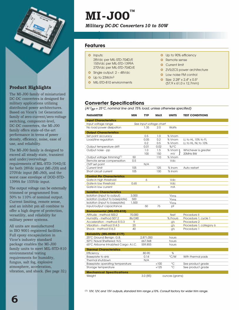
Product HighlightsThe MI-J00 family of miniaturized
DC-DC converters is designed for
military applications utilizing
distributed power architectures.
Based on Vicor’s 1st Generation
family of zero-current/zero-voltage
switching, component-level,
DC-DC converters, the MI-J00
family offers state-of-the-art
performance in terms of power
density, efficiency, noise, ease of
use, and reliability.
The MI-J00 family is designed to
exceed all steady-state, transient
and under/overvoltage
requirements of MIL-STD-704D/E
for both 28Vdc input (MI-J20) and
270Vdc input (MI-J60), and the
worst case envelope of DOD-STD-
1399A for 155Vdc input.
The output voltage can be externally
trimmed or programmed from
50% to 110% of nominal output.
Current limiting, remote sense,
and an inhibit pin all combine to
offer a high degree of protection,
versatility, and reliability for
military power systems.
All units are manufactured
in ISO 9001-registered facilities.
Full epoxy encapsulation in
Vicor’s industry standard
package enables the MI-J00
family units to meet MIL-STD-810
environmental testing
requirements for humidity,
fungus, salt fog, explosive
atmosphere, acceleration,
vibration, and shock. (See page 32.)
MI-J00TM
Military DC-DC Converters 10 to 50W
6
Inputs:28Vdc per MIL-STD-704D/E155Vdc per MIL-STD-1399A270Vdc per MIL-STD-704D/E
Single output: 2 – 48Vdc
Up to 23W/in3
MIL-STD-810 environments
Up to 90% efficiency
Remote sense
Current limit
ZVS/ZCS power architecture
Low noise FM control
Size: 2.28" x 2.4" x 0.5"(57,9 x 61,0 x 12,7mm)
PARAMETER MIN TYP MAX UNITS TEST CONDITIONS
Input CharacteristicsInput voltage range See input voltage chartNo load power dissipation 1.35 2.0 Watts
Output CharacteristicsSet point accuracy 0.5 1.0 % VnomLoad/line regulation 0.05 0.2 % Vnom LL to HL, 10% to FL
0.2 0.5 % Vnom LL to HL, NL to 10%Output temperature drift 0.01 0.02 %/°COutput noise - pp 1.0 1.5 % Vnom Whichever is greater
100 150 mV 20MHz BWOutput voltage trimming(1) 50 110 % VnomRemote sense compensation 0.5 VdcOVP set point N/ACurrent limit 105 125 % Inom Auto restartShort circuit current 105 130 % Inom
Control Pin CharacteristicsGate-in high threshold 6 VdcGate-in low threshold 0.65 VdcGate-in low current 6 mA
Isolation CharacteristicsIsolation (input to output) 3,000 VrmsIsolation (output to baseplate) 500 VrmsIsolation (input to baseplate) 1,500 VrmsInput/output capacitance 50 75 pF
Environmental (MIL-STD-810)Altitude - method 500.2 70,000 feet Procedure IIHumidity - method 507.2 86/240 %/hours Procedure 1, cycle 1Acceleration - method 513.3 9 g's Procedure 2Vibration - method 514.3 20 g's Procedure 1, category 6Shock - method 516.3 40 g's Procedure 1
Reliability (MIL-HDBK-217F)25°C Ground Benign: G.B. 2,871,050 hours50°C Naval Sheltered: N.S. 667,568 hours65°C Airborne Inhabited Cargo: A.I.C. 559,855 hours
Thermal CharacteristicsEfficiency 80-90 %Baseplate to sink 0.14 °C/W With thermal padsThermal shutdown N/ABaseplate operating temperature +100 °C See product grade Storage temperature +125 °C See product grade
Mechanical SpecificationsWeight 3.0 (85) ounces (grams)
Converter Specifications(At TBP = 25°C, nominal line and 75% load, unless otherwise specified)
(1) 10V, 12V, and 15V outputs, standard trim range ±10%. Consult factory for wider trim range.
Features

Configuration Chart
MI - J -Semi-custom modules available:Consult factory.
(1) 16V operation at 75% load.
(2) These units rated at 75% load from 125-150Vin:
MI-J6Z-xYMI-J6Y-xYMI-J60-xY
28Vdc input per MIL-STD 704D/E155Vdc input per DOD-STD-1399A270Vdc input per MIL-STD-704D/E
Product Grade Specifications
5
6
7
8
94
3
2
1
0.080 Dia (2) placesSolder plateover copper alloy
0.040 (1,0) Dia (7) placesSolder plateover copper alloy
.01
Aluminum Base
Product IDthis surface
Function +In
–In +Out
Trim–Sense –Out
Pin # 1 2 3 4 5 6 7 8 9
FULL R
+0.030 (0,76)-0.000 (0)
(5,6) Min.(7,6) Min. (44,4) Max.
2.40
2.28
0.12
0.50
1.90
0.65(16,5)
0.49(12,4)
0.30±0.015 (7,6)±(0,38)
0.15
2.10(53,4)
1.30
0.40(10,2)
0.35± 0.015 (8,9)±(0,38)
1.40(35,6)1.00
(25,4)0.70 (17,8)
Gate In Gate Out
+Sense
MI-J00
(57,9)
(33,0)
(3,8) 0.15 (3,8)
0.30 (61,0)
1.75 (48,3) 0.22
(3,0)
(12,7)
*Test data available for review or download from vicorpower.com
Mechanical Drawing
7
Output Power/Current≥5V <5V
A = 10W —oZ = 25W 5AY = 50W 10A
Product Grade Operating Temp.I = -40°C to +100°C
M = -55°C to +100°C
PARAMETER PRODUCT GRADEI -Grade M-Grade
Storage temperature -55°C to +125°C -65°C to +125°C
Operating temperature (baseplate) -40°C to +100°C -55°C to +100°C
Power cycling burn-in 12 hours, 25 cycles 96 hours, 200 cycles
Temperature cycled with power off48 hours, 12-16 cycles 48 hours, 12-16 cycles
-55°C to +100°C -65°C to +100°C
Test data supplied at these temperatures* -40°C, +80°C -55°C, +80°C
Warranty 2 years 2 years
Environmental compliance MIL-STD-810 MIL-STD-810
Derating NAVMAT P-4855-1A NAVMAT P-4855-1A
Input VoltageNominal Range Transient2 = 28V 18 – 50V
(1)60V
5 = 155V 100 – 210V 230V6 = 270V 125 – 400V
(2)475V
7 = 165V 100 – 310V
Output VoltageZ = 2V T = 6.5V N = 18.5VY = 3.3V R = 7.5V 3 = 24V0 = 5V M= 10V L = 28VX = 5.2V 1 = 12V J = 36VW= 5.5V P = 13.8V K = 40VV = 5.8V 2 = 15V 4 = 48V
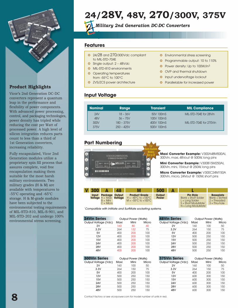
Product HighlightsVicor’s 2nd Generation DC-DC
converters represent a quantum
leap in the performance and
flexibility of power components.
With advanced power processing,
control, and packaging technologies,
power density has tripled while
reducing the cost per Watt of
processed power. A high level of
silicon integration reduces parts
count to less than a third of
1st Generation converters,
increasing reliability.
Fully encapsulated, Vicor 2nd
Generation modules utilize a
proprietary spin fill process that
assures complete, void free
encapsulation making them
suitable for the most harsh
military environments. Two
military grades (H & M) are
available with temperatures to
-55°C operating and -65°C
storage. H & M-grade modules
have been subjected to the
environmental testing requirements
of MIL-STD-810, MIL-S-901, and
MIL-STD-202 and undergo 100%
environmental stress screening.
24/28V, 48V, 270/300V, 375VMilitary 2nd Generation DC-DC Converters
8
24/28 and 270/300Vdc compliant to MIL-STD-704E
Single output: 2 – 48Vdc
MIL-STD-810 environments
Operating temperaturesfrom -55°C to 100°C
ZVS/ZCS power architecture
Environmental stress screening
Programmable output: 10 to 110%
Power density: Up to 100W/in3
OVP and thermal shutdown
Input undervoltage lockout
Parallelable for increased power
V 300 A 48 M 500 A LInput Package Output Product Grade Output Pin Style Baseplate
Voltage A = Maxi Voltage H = –40°C to +100°C Power Blank = Short Solder Blank = SlottedB = Mini M = –55°C to +100°C L = Long Solder 2 = ThreadedC = Micro S = Short ModuMate1 3 = Thru-hole
N = Long ModuMate1
Maxi Converter Example: V300A48M500AL300Vin, maxi, 48Vout @ 500W, long pins
Mini Converter Example: V300B15M250AL 300Vin, mini, 15Vout @ 250W, long pins
Micro Converter Example: V300C24M150A 300Vin, micro, 24Vout @ 150W, short pins
Part Numbering
1Compatible with InMate and SurfMate socketing systems.
Features
Contact factory or see vicorpower.com for model number of units in red.
24Vin Series Output Power (Watts)Output Voltage (Vdc) Maxi Mini Micro
2V 160 80 403.3V 264 132 755V 400 200 100
12V 400 200 10015V 400 200 10024V 400 200 10028V 400 200 10048V 400 200 100
300Vin Series Output Power (Watts)Output Voltage (Vdc) Maxi Mini Micro
2V 160 100 503.3V 264 150 755V 400 200 100
12V 500 250 15015V 500 250 15024V 500 250 15028V 500 250 15048V 500 250 150
48Vin Series Output Power (Watts)Output Voltage (Vdc) Maxi Mini Micro
2V 160 100 503.3V 264 150 755V 400 200 100
12V 500 250 15015V 500 250 15024V 500 250 15028V 500 250 15048V 500 250 150
375Vin Series Output Power (Watts)Output Voltage (Vdc) Maxi Mini Micro
2V 160 100 503.3V 264 150 755V 400 200 100
12V 600 300 15015V 600 300 15024V 600 300 15028V 600 300 15048V 600 300 150
Nominal Range Transient MIL Compliance
24V 18 – 36V 50V 100mS MIL-STD-704E for 28Vin48V 36 – 75V 100V 100mS
300V 180 – 375V 400V 100mS MIL-STD-704E for 270Vin375V 250 – 425V 500V 100mS
Input Voltage

Module Enable/Disable. The module may
be disabled by pulling PC below 2.3V with
respect to the –Input. This may be done
with an open collector transistor, relay, or
optocoupler. Multiple converters may be
disabled with a single transistor or relay
either directly or via “OR’ing” diodes.
See Figure 1.
Module Alarm.The module contains
“watchdog” circuitry which monitors input
voltage, operating temperature, and internal
operating parameters. In the event that any
of these parameters are outside of their
allowable operating range, the module will
shut down and PC will go low. PC will
periodically go high and the module will
check to see if the fault (as an example,
overtemperature) has cleared. If the fault
has not been cleared, PC will go low again
and the cycle will restart. The SC pin will
go low in the event of a fault and return to
its normal state after the fault has been
cleared. See Figures 2 and 3. 9
PARAMETER MIN TYP MAX UNITS NOTESInput CharacteristicsUndervoltage turn-on 24V 17.5 17.9 Vdc
48V 34.9 35.7 Vdc300V 174.6 178.2 Vdc375V 242.5 247.5 Vdc
Undervoltage turn-off 24V 14.74 15.3 Vdc48V 29.4 30.5 Vdc300V 147.4 152.8 Vdc375V 204.7 212.2 Vdc
Overvoltage turn-off/on 24V 36.3 37.8 39.6 Vdc48V 75.7 78.8 82.5 Vdc300V Not Included Vdc375V 429.2 446.3 467.5 Vdc
Output CharacteristicsLine regulation ±0.02 ±0.20 % Low line to high line; full loadTemperature regulation ±0.002 ±0.005 %/°C Over operating temperature rangePower sharing accuracy ±2 ±5 % 10 to 100% of full load
For trimming below 90% ofProgramming range 10 110 % Vnom nominal, a minimum load
may be required.Current limit 115 % Iout Output voltage 95% of nominalShort circuit current 115 % Iout Output voltage < 250mV
Isolation Characteristics
Isolation voltage (in to out) 3000 Vrms Complies with reinforced insulation requirements
Isolation voltage (in to base) 1550 Vrms Complies with basicinsulation requirements
Isolation voltage (out to base) 500 Vrms Complies with operational insulation requirements
Isolation resistance (in to out) 10 Megohms
RATING UNIT NOTESThermal CharacteristicsOperating temperature (H-grade) -40 to +100 °C BaseplateStorage temperature (H-grade) -55 to +125 °COperating temperature (M-grade) -55 to +100 °C BaseplateStorage temperature (M-grade) -65 to +125 °CTemperature limiting (typical) 115 °C
Environmental Stress Screening See page 30 for details
General Specifications (See vicorpower.com for model specific data sheets)
Specifications
Control Functions - PC Pin+In
PC
PR
–In
Disable
Disable = PC <2.3V
Figure 1 – Module enable/disable
Figure 2 – PC/SC module alarm logic
Figure 3 – PC/SC module alarm timing
+Out
+S
SC
–S
–Out
+In
PC
PR
–In
Input Undervoltage
2-20ms typ.f (VIN)
AutoRestart
5.7Vdc(0-3mA)
50Ω
SW2 SW3
1.23Vdc 6K
1K
SW1
SW1, 2, & 3shown in
"Fault" position
Input OvervoltageOvertemperatureModule Faults
2-20ms typ.
Fault
SC
PC
1.23V
5.7V40µs typ.

10
Control Functions - SC Pin
Control Functions - PR Pin
Output Voltage Programming. The output voltage of the converter can be adjusted or
programmed via fixed resistors, potentiometers, or voltage DACs. See Figures 4 and 5.
RU (ohms) = 1,000 (Vout-1.23) Vnom
– 1,0001.23 (Vout-Vnom)
RD (ohms) = 1,000 Vout
Vnom - Vout
Trim-Down. 1. This converter is not a constant power
device – it has a constant current limit.
Hence, available output power is reduced
by the same percentage that output
voltage is trimmed down. Do not exceed
maximum rated output current.
2. The trim-down resistor must
be connected to the –Sense pin
(–Out pin on a micro).
Trim-Up. 1. The converter is rated for a maximum
delivered power. To ensure that
maximum rated power is not
exceeded, reduce maximum output
current by the same percentage
increase in output voltage.
2. The trim-up resistor must be
connected to the +Sense pin.
(+Out pin on a micro).
3. Do not trim the converter above
maximum trim range (typically +10%)
or the output overvoltage protection
circuitry may be activated.
Parallel Operation. The PR pin supports paralleling for
increased power with N+1 (N+M)
redundancy and phased array capability.
Modules of the same input voltage,
output voltage, and power level will
current share if all PR pins
are suitably interfaced.
Compatible interface architectures include:
DC coupled single-wire interface. All PR
pins are directly connected to one
another. This interface supports current
sharing but is not fault tolerant. Minus In
pins must be tied to the same electric
potential. See Figure 6.
AC coupled single-wire interface. All PR
pins are connected to a single communication
bus through 0.001µF (500V) capacitors.
This interface supports current sharing
and is fault tolerant except for the
communication bus. See Figure 7.
+Out
+S
SC
–S
–Out
RUTrim Up LoadError
Amp
1kΩ
1.23V
0.033µF
Figure 5 – Output voltage trim-up circuit(Micro inset)
Load
+Out
+S
SC
–S
–Out
RDTrim Down
ErrorAmp
1kΩ
1.23V
0.033µF
Figure 4 – Output voltage trim-down circuit(Micro inset)
+In
PC
PR
–In
Module 2(up to 12)
+In
PC
PR
–In
Module 1
Ground plane
Figure 7 – AC coupled single-wire interface
+In
PC
PR
–In
Module 2(up to 12)
+In
PC
PR
–In
Module 1
Ground plane
Figure 6 – DC coupled single-wire interface
0.001µF
0.001µF
Load
RDTrim Down
ErrorAmp
1kΩ
1.23V
0.033µF
+Out
SC
–Out
RUTrim Up
LoadErrorAmp
1kΩ
1.23V
0.033µF
+Out
SC
–Out
Note:Please consult theappropriate Vicor DesignGuide for additionalinformation regarding theuse of these products.

Pin Styles
Tin/LeadHot Solder Dip (Pin Style 1&2)
Gold Plated Copper (Pin Style S&N)
Pin Styles
Tin/LeadHot Solder Dip (Pin Style 1&2)
Gold Plated Copper (Pin Style S&N)
1.7444,2
2.2055,9
56789
4321
0.235,8
(REF)
0.1804,57
0.0802,03
1.40035,56
1.00025,40
0.70017,78
0.40010,16
DIA,(7X)
DIA,(2X)
4-40 UNC-2BThru (4X)***
(Style 2 and 3 only)
Slotted (Style 1)
or
Threaded (Style 2) 4-40 UNC-2B (6X)
or
Thru Hole (Style 3) #30 Drill Thru (6X)(0.1285)
0.5012,7
0.061,5 2.20
55,9(REF)
1.8045,7
4.60116,8
3.6091,4
0.133,3
FULL R (6X)
(6X)
R (3X)
CHAMFER
0.102,5
X 45°
0.5413,7
0.4310,9
0.389,6
0.20**5,08
0.12*3,1
(2X)
0.01
Use a4-40 Screw (6x)
Torque to:5 in-lbs
0.57 N-m
Pin Style 2&N(Long Pin)
0.6215,7
Pin Style 1&S(Short Pin)
(9X)
(9X)
(ALL M
AR
KIN
GS
TH
IS S
UR
FAC
E)
ALUMINUM BASEPLATE
0.50 ±0.0212,7 ±0,5
* Style 1 baseplate only ** Style 2 & 3 baseplates *** Reserved for Vicor accessories Not for mounting
4.200106,68
0.300±0.0157,62±0,38
0.300±0.0157,62±0,38
2.0050,8
0.102,5
(2X)
0.01
0.358,8
0.20**5,1
0.12*3,1
DIA,(7X)
0.1503,81
(REF)
DIA,(2X)
0.0802,03
431
9 8
2
7 6 5
0.235,8
0.40010,16
1.40035,56
1.00025,40
0.70017,78
2.2055,91.7444,2
FULL R (6X)
(6X)
(REF.)
0.102,5
1.3033,0
2.2857,9
2.2055,9
0.130
3,30
0.4912,4
0.6516,5
0.061,5
R (3X)
X 45˚
CHAMFER
Use a 4-40 Screw (6X)Torque to:
5 in-lbs.57 N-m
0.5413,7
0.4310,9
Pin Style 2&N(Long Pin)
0.6215,7
Pin Style 1&S(Short Pin)
(9X)
(9X)
(ALL M
AR
KIN
GS
T
HIS
SU
RFA
CE
)
ALUMINUM BASEPLATE
style 2 & 3 baseplates only(4X)***
0.300 ±0.0157,62 ±0,38
.300 ±0.0157,62 ±0,38
1.90048,26
2.00050,80
0.102,5
567
4321
(REF)
0.0802,03
DIA. (7X)
0.215,2
0.27
6,9(2X)
1.0426,4
1.4536,8
0.275
6,99
0.80020,32
0.52513,34
0.40010,16
0.12*
3,1
0.20**
5,08
FULL R (6X)
0.102,5
CHAMFER
(REF.)
(6X)
0.6516,5
0.4912,4
1.3033,0
2.2857,9
1.4536,8
0.133,3
0.06
1,5R (3X)
0.01
X 45˚
Use a4-40 Screw (6x)
Torque to:5 in-lbs
0.57 N-m
0.5413,7
0.4310,9
Pin Style 2&N(Long Pin)
0.6215,7
Pin Style 1&S(Short Pin)
(7X)
(7X)
(ALL M
AR
KIN
GS
TH
IS S
UR
FAC
E)
ALUMINUM BASEPLATE
style 2 & 3 baseplates only(4X)***
0.490 ±.015
12,45 ±0,38(REF)
2.00050,80
0.235±.0155,97±0,38
(REF)
0.350±.0158,89±0,38
(REF)
1.2732,3
0.092,3
Mechanical Drawing
11
Converter Pins
No. Function Label
1 +In +
2Primary
PCControl
3 Parallel PR
4 –In –
5 –Out –
6 –Sense –S
7Secondary
SCControl
8 +Sense +S
9 +Out +
Converter Pins
No. Function Label
1 +In +
2Primary
PCControl
3 Parallel PR
4 –In –
5 –Out –
6 –Sense –S
7Secondary
SCControl
8 +Sense +S
9 +Out +
Converter Pins
No. Function Label
1 +In +
2Primary
PCControl
3 Parallel PR
4 –In –
5 –Out –
6Secondary
SCControl
7 +Out +
Maxi
Mini
Micro
Pin Styles
Tin/LeadHot Solder Dip (Pin Style 1&2)
Gold Plated Copper (Pin Style S&N)
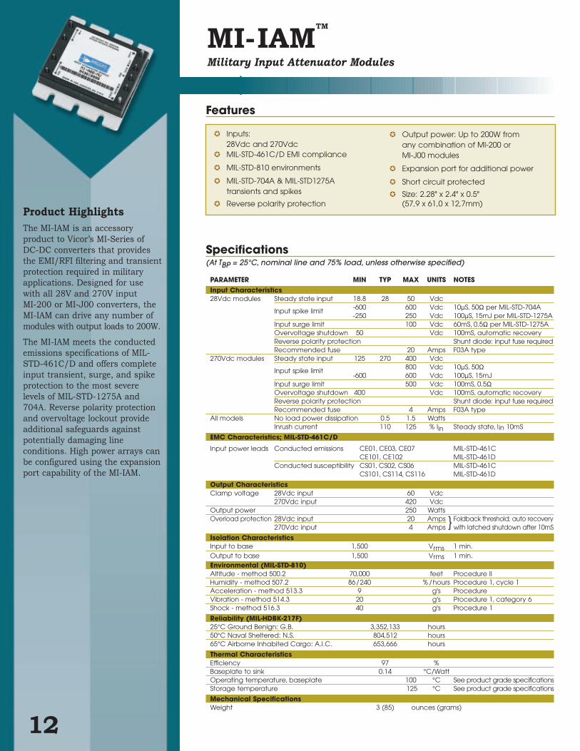
Product HighlightsThe MI-IAM is an accessory
product to Vicor’s MI-Series of
DC-DC converters that provides
the EMI/RFI filtering and transient
protection required in military
applications. Designed for use
with all 28V and 270V input
MI-200 or MI-J00 converters, the
MI-IAM can drive any number of
modules with output loads to 200W.
The MI-IAM meets the conducted
emissions specifications of MIL-
STD-461C/D and offers complete
input transient, surge, and spike
protection to the most severe
levels of MIL-STD-1275A and
704A. Reverse polarity protection
and overvoltage lockout provide
additional safeguards against
potentially damaging line
conditions. High power arrays can
be configured using the expansion
port capability of the MI-IAM.
MI-IAMTM
Military Input Attenuator Modules
12
Inputs:28Vdc and 270Vdc
MIL-STD-461C/D EMI compliance
MIL-STD-810 environments
MIL-STD-704A & MIL-STD1275A transients and spikes
Reverse polarity protection
Output power: Up to 200W fromany combination of MI-200 or MI-J00 modules
Expansion port for additional power
Short circuit protected
Size: 2.28" x 2.4" x 0.5"(57,9 x 61,0 x 12,7mm)
Specifications(At TBP = 25°C, nominal line and 75% load, unless otherwise specified)
PARAMETER MIN TYP MAX UNITS NOTESInput Characteristics28Vdc modules Steady state input 18.8 28 50 Vdc
Input spike limit -600 600 Vdc 10µS, 50Ω per MIL-STD-704A-250 250 Vdc 100µS, 15mJ per MIL-STD-1275A
Input surge limit 100 Vdc 60mS, 0.5Ω per MIL-STD-1275AOvervoltage shutdown 50 Vdc 100mS, automatic recoveryReverse polarity protection Shunt diode: input fuse requiredRecommended fuse 20 Amps F03A type
270Vdc modules Steady state input 125 270 400 Vdc
Input spike limit 800 Vdc 10µS, 50Ω-600 600 Vdc 100µS, 15mJ
Input surge limit 500 Vdc 100mS, 0.5ΩOvervoltage shutdown 400 Vdc 100mS, automatic recoveryReverse polarity protection Shunt diode: input fuse requiredRecommended fuse 4 Amps F03A type
All models No load power dissipation 0.5 1.5 WattsInrush current 110 125 % Iin Steady state, lin 10mS
EMC Characteristics; MIL-STD-461C/D
Input power leads Conducted emissions CE01, CE03, CE07 MIL-STD-461CCE101, CE102 MIL-STD-461D
Conducted susceptibility CS01, CS02, CS06 MIL-STD-461C CS101, CS114, CS116 MIL-STD-461D
Output CharacteristicsClamp voltage 28Vdc input 60 Vdc
270Vdc input 420 VdcOutput power 250 WattsOverload protection 28Vdc input 20 Amps Foldback threshold; auto recovery
270Vdc input 4 Amps with latched shutdown after 10mS
Isolation CharacteristicsInput to base 1,500 Vrms 1 min.Output to base 1,500 Vrms 1 min.Environmental (MIL-STD-810)Altitude - method 500.2 70,000 feet Procedure IIHumidity - method 507.2 86/240 % /hours Procedure 1, cycle 1Acceleration - method 513.3 9 g's Procedure Vibration - method 514.3 20 g's Procedure 1, category 6Shock - method 516.3 40 g's Procedure 1
Reliability (MIL-HDBK-217F)25°C Ground Benign: G.B. 3,352,133 hours50°C Naval Sheltered: N.S. 804,512 hours65°C Airborne Inhabited Cargo: A.I.C. 653,666 hours
Thermal CharacteristicsEfficiency 97 %Baseplate to sink 0.14 °C/WattOperating temperature, baseplate 100 °C See product grade specificationsStorage temperature 125 °C See product grade specifications
Mechanical SpecificationsWeight 3 (85) ounces (grams)
Features

MI-IAM Model Selection Chart
Product Grade Specifications
MI-IAM Safe Operating Area*
5
6
7
8
94
3
2
1
0.080 Dia (2) placesSolder plateover copper alloy
0.040 (1,0) Dia (7) placesSolder plateover copper alloy
.01
Aluminum Base
Product IDthis surface
Function +In
–In +Out
ParallelGate Out –Out
Pin # 1 2 3 4 5 6 7 8 9
FULL R
+0.030 (0,76)-0.000 (0)
(5,6) Min.(7,6) Min. (44,4) Max.
2.40
2.28
0.12
0.50
1.90
0.65(16,5)
0.49(12,4)
0.30±.015 (7,6)±(0,38)
0.15
2.10(53,4)
1.30
0.40(10,2)
0.35± 0.015 (8,9)±(0,38)
1.40(35,6)1.00
(25,4)0.70 (17,8)
+In –In
Gate In
VI-IAM
(57,9)
(33,0)
(3,8)
0.15 (3,8)
(48,3) 0.22
(3,0)
(12,7)
0.30
(61,0)
1.75
*Test data available for review or download from vicorpower.com
Mechanical Drawing
13
PARAMETER PRODUCT GRADEI -Grade M-Grade
Storage temperature -55°C to +125°C -65°C to +125°C
Operating temperature (baseplate) -40°C to +100°C -55°C to +100°C
Power cycling burn-in 12 hours, 25 cycles 96 hours, 200 cycles
Temperature cycled with power off48 hours, 12-16 cycles 48 hours, 12-16 cycles
-55°C to +100°C -65°C to +100°C
Test data supplied at these temperatures* -40°C, +80°C -55°C, +80°C
Warranty 2 years 2 years
Environmental compliance MIL-STD-810 MIL-STD-810
Derating NAVMAT P- 4855-1A NAVMAT P -4855-1A
MI-IAM
Gate OutParallelGate In
+Out
-Out-In
-In
+In
+In
+–
-Out
-S
+S
+Out+In
Gate In
Gate Out
-In
MI-Converter TrimC1
4700 pF
4700 pF
Input Voltage Range Capacitance (C1)28Vdc (18.8-50V) 390µF (Max.)270Vdc (125-400V) 27µF (Max.)
Model Number Nominal Input Voltage Input Range Compatible MI-Series Converter
MI-A22-MU 28Vdc 18.8–50Vdc MI-22x and MI-J2x-Mx M–grade
MI-A66-MU 270Vdc 125–400Vdc MI-26x and MI-J6x-Mx M–grade
MI-A22-IU 28Vdc 18.8–50Vdc MI-22x and MI-J2x-Ix I–grade
MI-A66-IU 270Vdc 125–400Vdc MI-26x and MI-J6x-Ix I–grade
Typical Connection Diagram
VO
LTS
-PE
AK
VA
LUE
OF
SP
IKE
VO
LTA
GE
TIME (SECONDS)
1s010
100ms-110
10ms-210
1ms-310
100µs-410
10µs-510
1µs-610
-600
-500
-400
-300
-200
-100
0
100
200
300
400
500
600
Ratings Exceeded
Reverse PolarityProtection
50VOVP
VO
LTS
-PE
AK
VA
LUE
OF
SP
IKE
VO
LTA
GE
TIME (SECONDS)
1s010
100ms-110
10ms-210
1ms-310
100µs-410
10µs-510
1µs-610
600
400
200
0
200
400
600
800Ratings Exceeded
Reverse PolarityProtection
500VOVP 400V
28Vdc Input 270Vdc Input
* Refer to input characteristics
MI-IAM

Product HighlightsThe M-FIAM is a DC front-end
module that provides EMI filtering
and transient protection required
in military applications. The
M-FIAM enables designers using
Vicor 2nd Generation 24V and
300V DC-DC converters to meet
conducted emission/conducted
susceptibility per MIL-STD-461E;
and input transients per
MIL-STD-704E.
M-FIAM is housed in an industry
standard "half brick" module
measuring 2.28" x 2.2" x 0.5".
M-FIAM3TM
& M-FIAM5TM
Military Input Attenuator Modules
14
MIL-STD-461E compliant
MIL-STD-704E input transient protection
MIL-STD-810, MIL-STD-202 environments
Environmental stress screening
Low profile mounting options
Inrush current limiting
Size: 2.28" x 2.2" x 0.5"(57,9 x 55,9x 12,7mm)
Reverse polarity protection
Specifications(At TBP = 25°C, nominal line and 75% load, unless otherwise specified)
PARAMETER MIN TYP MAX UNITS NOTESInput Characteristics28Vdc modules Steady state input 18 28 36 Vdc
Input transient 50 Vdc 100ms, MIL-STD-704EInrush limiting 0.007 A/µF
270Vdc modules Steady state input 180 270 375 VdcInput transient 400 Vdc 100ms, MIL-STD-704EInrush limiting 0.018 A/µF
EMC Characteristics; MIL-STD-461EInput power leads Conducted emissions CE101, CE102
Conducted susceptibility CS101, CS114, CS115, CS116
Output CharacteristicsOutput current 28Vdc input 20 Amps
270Vdc input 3 AmpsInternal voltage drop 28Vdc input 0.5 1.0 Vdc @ 20A, 100°C baseplate
270Vdc input 3.0 5.0 Vdc @ 3A, 100°C baseplate
Isolation CharacteristicsDielectric withstand 1,500 Vrms Input/output to base
2,121 Vdc Input/output to base.
Thermal CharacteristicsEfficiency 96 98 %Baseplate to sink; flat, greased surface 0.16 °C/WattBaseplate to sink; thermal pad (P/N 20264) 0.1 °C/WattBaseplate to ambient 7.9 °C/WattBaseplate to sink; 1000 LFM 2.2 °C/Watt
Model Nominal Input Compatible Number Input Voltage Range 2nd Generation Converters
M-FIAM5 xxx 28Vdc 18 – 36V V24 Series
M-FIAM3xxx 270Vdc 180 – 375V V300 Series
Part Numbering
M-FIAM Model Selection Chart
M FIAM 5 M 2 1Military Filter Input Input Voltage Product Grade Pin Style BaseplateProduct Attenuator Module 3 = 270Vdc H = –40°C to +100°C 1 = Short 1 = Slotted
5 = 28Vdc M = –55°C to +100°C 2 = Long 2 = ThreadedS = Short ModuMate1 3 = Thru-holeN = Long ModuMate1
1Compatible with SurfMate and InMate socketing systems.
Features
Product Grade Specifications
(2X)
0.01
0.358,8
0.20**5,1
0.12*3,1
DIA,(7X)
0.1503,81
(REF)
DIA,(2X)
0.0802,03
431
9 8
2
7 6 5
0.235,8
0.40010,16
1.40035,56
1.00025,40
0.70017,78
2.2055,91.7444,2
FULL R (6X)
(6X)
(REF.)
0.102,5
1.3033,0
2.2857,9
2.2055,9
0.130
3,30
0.4912,4
0.6516,5
0.061,5
R (3X)
X 45˚
CHAMFER
Use a 4-40 Screw (6X)Torque to:
5 in-lbs.57 N-m
0.5413,7
0.4310,9
Pin Style 2&N(Long Pin)
0.6215,7
Pin Style 1&S(Short Pin)
(9X)
(9X)
Slotted (Style 1)
or
Threaded (Style 2) 4-40 UNC-2B (6X)
or
Thru Hole (Style 3) #30 Drill Thru (6X)(0.1285)
(ALL M
AR
KIN
GS
T
HIS
SU
RFA
CE
)
ALUMINUM BASEPLATE
0.50 ±0.0212,7 ±0,5
* Style 1 baseplate only ** Style 2 & 3 baseplates *** Reserved for Vicor accessories Not for mounting
style 2 & 3 baseplates only(4X)***
0.300 ±0.0157,62 ±0,38
0.300 ±0.0157,62 ±0,38
1.90048,26
2.00050,80
0.102,5
*Test data available for review or download from vicorpower.com
Mechanical Drawing
15
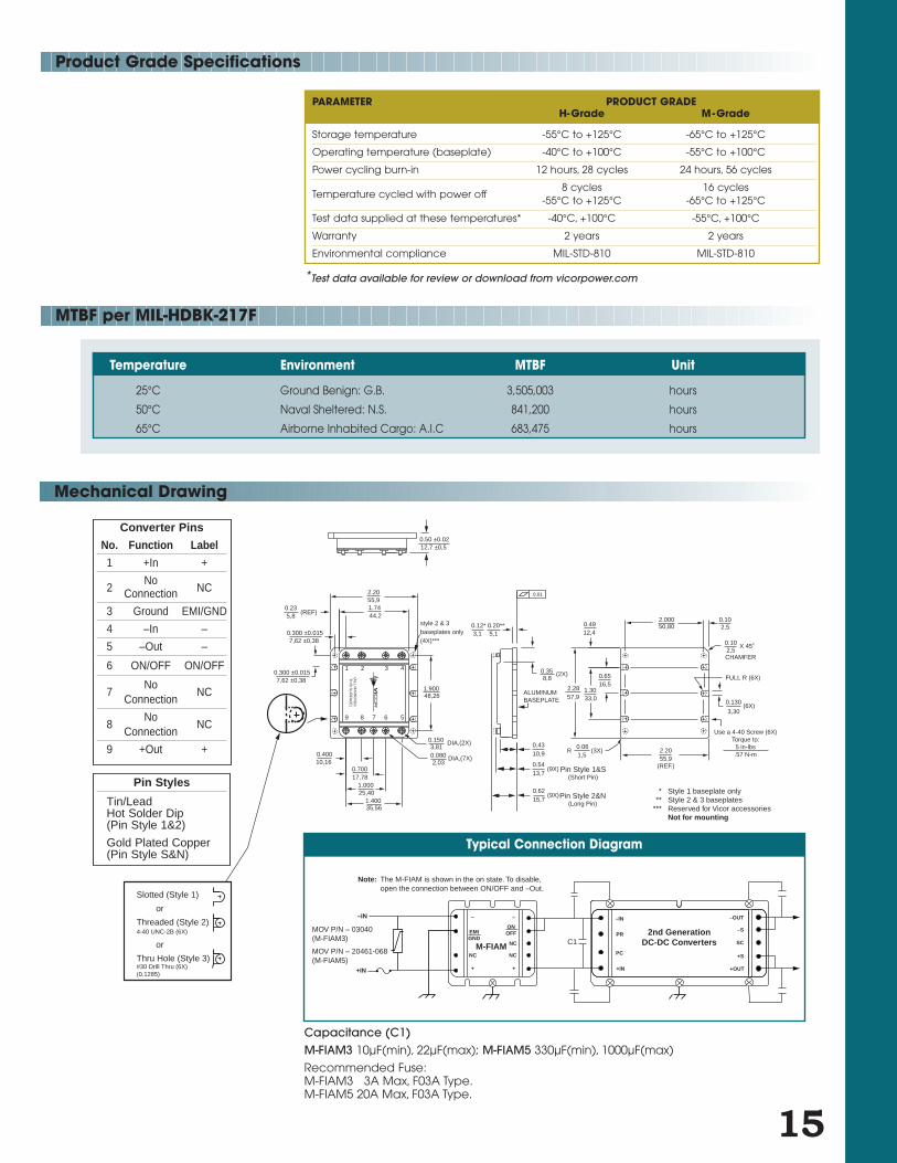
PARAMETER PRODUCT GRADEH-Grade M-Grade
Storage temperature -55°C to +125°C -65°C to +125°C
Operating temperature (baseplate) -40°C to +100°C -55°C to +100°C
Power cycling burn-in 12 hours, 28 cycles 24 hours, 56 cycles
Temperature cycled with power off8 cycles 16 cycles
-55°C to +125°C -65°C to +125°C
Test data supplied at these temperatures* -40°C, +100°C -55°C, +100°C
Warranty 2 years 2 years
Environmental compliance MIL-STD-810 MIL-STD-810
2nd GenerationDC-DC ConvertersM-FIAM
–IN
PR
PC
+IN
–OUT
–S
SC
+S
+OUT
–
EMIGND
NC
+ +
NC
NC
ONOFF
– –IN
+IN
Note: The M-FIAM is shown in the on state. To disable, open the connection between ON/OFF and –Out.
MOV P/N – 03040(M-FIAM3)
MOV P/N – 20461-068(M-FIAM5)
C1
MTBF per MIL-HDBK-217F
Temperature Environment MTBF Unit
25°C Ground Benign: G.B. 3,505,003 hours
50°C Naval Sheltered: N.S. 841,200 hours
65°C Airborne Inhabited Cargo: A.I.C 683,475 hours
Typical Connection Diagram
Converter Pins
No. Function Label
1 +In +
2No
NCConnection
3 Ground EMI/GND
4 –In –
5 –Out –
6 ON/OFF ON/OFF
7No
NCConnection
8No
NCConnection
9 +Out +
Capacitance (C1)M-FIAM3 10µF(min), 22µF(max); M-FIAM5 330µF(min), 1000µF(max)
Recommended Fuse:M-FIAM3 3A Max, F03A Type.M-FIAM5 20A Max, F03A Type.
Pin Styles
Tin/LeadHot Solder Dip (Pin Style 1&2)
Gold Plated Copper (Pin Style S&N)
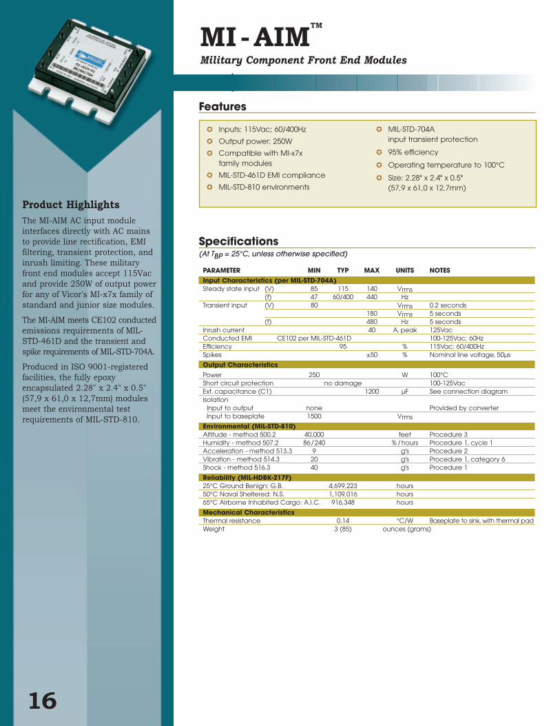
Product HighlightsThe MI-AIM AC input module
interfaces directly with AC mains
to provide line rectification, EMI
filtering, transient protection, and
inrush limiting. These military
front end modules accept 115Vac
and provide 250W of output power
for any of Vicor's MI-x7x family of
standard and junior size modules.
The MI-AIM meets CE102 conducted
emissions requirements of MIL-
STD-461D and the transient and
spike requirements of MIL-STD-704A.
Produced in ISO 9001-registered
facilities, the fully epoxy
encapsulated 2.28" x 2.4" x 0.5"
(57,9 x 61,0 x 12,7mm) modules
meet the environmental test
requirements of MIL-STD-810.
MI-AIMTM
Military Component Front End Modules
16
Inputs: 115Vac; 60/400Hz
Output power: 250W
Compatible with MI-x7x family modules
MIL-STD-461D EMI compliance
MIL-STD-810 environments
MIL-STD-704A input transient protection
95% efficiency
Operating temperature to 100°C
Size: 2.28" x 2.4" x 0.5"(57,9 x 61,0 x 12,7mm)
Specifications(At TBP = 25°C, unless otherwise specified)
PARAMETER MIN TYP MAX UNITS NOTESInput Characteristics (per MIL-STD-704A)Steady state input (V) 85 115 140 Vrms
(f) 47 60/400 440 HzTransient input (V) 80 Vrms 0.2 seconds
180 Vrms 5 seconds(f) 480 Hz 5 seconds
Inrush current 40 A, peak 125VacConducted EMI CE102 per MIL-STD-461D 100-125Vac; 60HzEfficiency 95 % 115Vac; 60/400HzSpikes ±50 % Nominal line voltage, 50µs
Output CharacteristicsPower 250 W 100°CShort circuit protection no damage 100-125VacExt. capacitance (C1) 1200 µF See connection diagramIsolation
Input to output none Provided by converterInput to baseplate 1500 Vrms
Environmental (MIL-STD-810)Altitude - method 500.2 40,000 feet Procedure 3Humidity - method 507.2 86/240 % / hours Procedure 1, cycle 1Acceleration - method 513.3 9 g's Procedure 2Vibration - method 514.3 20 g's Procedure 1, category 6Shock - method 516.3 40 g's Procedure 1
Reliability (MIL-HDBK-217F)25°C Ground Benign: G.B. 4,699,223 hours50°C Naval Sheltered: N.S. 1,109,016 hours65°C Airborne Inhabited Cargo: A.I.C. 916,348 hours
Mechanical CharacteristicsThermal resistance 0.14 °C/W Baseplate to sink, with thermal padWeight 3 (85) ounces (grams)
Features
Product Grade Specifications
*Test data available for review or download from vicorpower.com
Mechanical Drawing
UniversalAC In
MI-AIM
Gate Out
Parallel
Gate In
+Out
-OutL2/N
N/C
N/C
L1
-Out
-S
Trim
+S
+Out+In
Gate In
Gate Out
-In
MI-27x/J7xDriver Load
F2
0.01 µF (Two 4700 pF )Y-Rated Capacitors
0.01 µF Ceramic
0.01 µF Ceramic
C out*
F1
* 1200µF Max. (See Vicor's Applications Manual, page 12-2, Selecting Capacitors for AIM Modules.)
Fuse 1: 7A F03A type recommended.Fuse 2: For MI-x7x-xx – Buss PC-Tron 2.5A (450V)
0.01 µF (Two 4700 pF )Y-Rated Capacitors
0.47 µF
Connection Diagram
17
PARAMETER PRODUCT GRADEI -Grade M-Grade
Part Number MI-AIM-I1 MI-AIM-M1
Storage temperature -55°C to +125°C -65°C to +125°C
Operating temperature (baseplate) -40°C to +100°C -55°C to +100°C
Power cycling burn-in 12 hours, 25 cycles 96 hours, 200 cycles
Temperature cycled with power off48 hours, 12-16 cycles 48 hours, 12-16 cycles
-55°C to +100°C -65°C to +100°C
Test data supplied at these temperatures* -40°C, +80°C -55°C, +80°C
Warranty 2 years 2 years
Environmental compliance MIL-STD-810 MIL-STD-810
5
6
7
8
94
3
2
1
0.080 Dia (2) placesSolder plateover copper alloy
0.040 (1,0) Dia (7) placesSolder plateover copper alloy
.01
Aluminum Base
Product IDthis surface
Function L1
L2/N +Out
ParallelGate Out –Out
Pin # 1 2 3 4 5 6 7 8 9
FULL R
+0.030 (0,76)-0.000 (0)
(5,6) Min.(7,6) Min.
(44,4) Max.
2.40
2.28
0.12
0.50
1.90
0.65(16,5)
0.49(12,4)
0.30±.015 (7,6)±(0,38)
0.15
2.10(53,4)
(33,0)
0.40(10,2)
0.35± 0.015 (8,9)±(0,38)
1.40(35,6)1.00
(25,4)0.70 (17,8)
NC NC
Gate In
MI-AIM
(57,9)1.30
(3,8) 0.15 (3,8)
(48,3)
(3,0)
0.22
(12,7)
0.30 (61,0)
1.75
Mechanical Drawing
5
6
7
8
94
3
2
1
0.080 Dia (2) placesSolder plateover copper alloy
0.040 (1,0) Dia (7) placesSolder plateover copper alloy
0.01Aluminum Base
Product IDthis surface
Function +In
–In +Out
NC–Sense –Out
Pin # 1 2 3 4 5 6 7 8 9
FULL R
+0.030 (0,76)-0.000 (0)
(5,6) Min.(7,6) Min.
(44,4) Max.
2.40
2.28
0.12
0.50
1.90
0.65(16,5)
0.49(12,4)
0.30±0.015(7,6)±(0,38)
0.15
2.10(53,4)
1.30
0.40(10,2)
0.35± 0.015 (8,9)±(0,38)
1.40(35,6)1.00
(25,4)0.70 (17,8)
+Sense In –Sense In
+Sense
MI-RAM
(57,9)
(33,0)
(3,8)
0.15 (3,8)
(48,3)
(3,0)
0.22
(12,7)
0.30 (61,0)
1.75
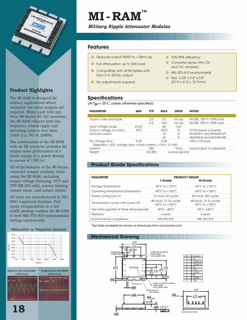
PARAMETER MIN TYP MAX UNITS NOTES
Output noise and ripple 2.0 3.0 mV pp MI-200; 10% to 100% load 6.0 10.0 mV pp MI-J00; 10% to 100% load
Input voltage range 5Vdc 50 VdcOutput voltage accuracy 99.5 100.5 % Of MI source converterFull load current 10 A MI-RAM-I1 and MI-RAM-M1
20 A MI-RAM-I2 and MI-RAM-M2DC voltage drop 0.34 0.38 10% to full load
Dissipation = (DC voltage drop x load current) + (Vin x 15 mA)Isolation 250 Vrms Input/output to baseplate Weight 3.0 (85) ounces (grams)
Input to the converter (10V/cm)
Output from the RAM (2mV/cm)
60 db
55 db
25 db
30 db
35 db
40 db
45 db
50 db
10 MHz1 MHz100 KHz10 KHz1 KHz100 Hz10 Hz
Frequency
Atte
nuat
ion
Attenuation vs. Frequency (typical)
Product Highlights
The MI-RAM is designed for
military applications where
extremely low noise outputs are
required. When used with any
Vicor MI-Series DC-DC converter,
the MI-RAM reduces both line
frequency related ripple and
switching noise to less than
10mV p-p, DC to 20MHz.
The combination of the MI-RAM
with an MI converter provides the
output noise performance of a
linear supply at a power density
in excess of 15W/in3.
All of the features of the MI-Series
converter remain available while
using the MI-RAM, including
output voltage trimming, OVP and
OTP (MI-200 only), current limiting,
remote sense, and output inhibit.
All units are manufactured in ISO
9001-registered facilities. Full
epoxy encapsulation in a low
profile package enables the MI-RAM
to meet MIL-STD-810 environmental
testing requirements.
MI-RAMTM
Military Ripple Attenuator Modules
18
Reduces output PARD to <10mV pp
Full attenuation up to 20A load
Compatible with all MI-Series units from 5 to 50Vdc output
No adjustments required
93%-99% efficiency
Converter sense, trim, OV and OC retained
MIL-STD-810 environments
Size: 2.28" x 2.4" x 0.5"(57,9 x 61,0 x 12,7mm)
Specifications(At TBP = 25°C, unless otherwise specified)
Product Grade Specifications
Features
*Test data available for review or download from vicorpower.com
PARAMETER PRODUCT GRADEI -Grade M-Grade
Storage temperature -55°C to +125°C -65°C to +125°C
Operating temperature (baseplate) -40°C to +100°C -55°C to +100°C
Power cycling burn-in 12 hours, 25 cycles 96 hours, 200 cycles
Temperature cycled with power off48 hours, 12-16 cycles 48 hours, 12-16 cycles
-55°C to +100°C -65°C to +100°C
Test data supplied at these temperatures* -40°C, +80°C -55°C, +80°C
Warranty 2 years 2 years
Environmental compliance MIL-STD-810 MIL-STD-810

19
Mechanical Drawing
567
4321
(REF)
0.0802,03
DIA. (7X)
0.215,2
0.27
6,9(2X)
1.0426,4
1.4536,8
.275
6,99
0.80020,32
0.52513,34
0.40010,16
0.12*
3,1
0.20**
5,08
0.01
0.5413,7
0.4310,9
Pin Style 2&N(Long Pin)
0.6215,7
Pin Style 1&S(Short Pin)
(7X)
(7X)
Slotted (Style 1)
or
Threaded (Style 2) 4-40 UNC-2B (6X)
or
Thru Hole (Style 3) #30 Drill Thru (6X)(0.1285)
(ALL M
AR
KIN
GS
TH
IS S
UR
FAC
E)
ALUMINUM BASEPLATE
12,7 ±0,5
0.50 ±0.02
* Style 1 baseplate only ** Style 2 & 3 baseplates *** Reserved for Vicor accessories Not for mounting
style 2 & 3 baseplates only(4X)***
0.490 ±.015
12,45 ±0,38(REF)
INO
UT
uRA
M
2.00050,80
0.235±.0155,97±0,38
(REF)
0.350±.0158,89±0,38
(REF)
0.6516,5
0.4912,4
1.3033,0
2.2857,9
0.06
1,5R (3X)
PARAMETER MIN TYP MAX UNITS NOTES
Output ripple 10.0 mV p–pInput voltage range 3.0 30.0 VdcOperating current
uRAM2xxx 0.02 20 A No internal current limitinguRAM3xxx 0.02 30 A No internal current limiting
Power DissipationuRAM2xxx VHR 380mV@1A 7.5 W VIN 28V; Iout 20AuRAM3xxx VHR 380mV@1A 11.5 W VIN 28V; Iout 30A
MicroRAMTM
Output Ripple Attenuator Modules
>40dB ripple attenuation from 60Hz to 1MHz
20-30 Amp ratings
3-30Vdc input range
Efficiency up to 98%
Envronmental stress screening
Integrated OR’ing diode supports N+1 redundancy
Combined active and passive filtering
Size: 2.28" x 1.45" x 0.5"
(57,9 x 36,8 x 12,7mm)
Specifications(At TBP = 25°C, unless otherwise specified)
Features
Part Numbering
1Compatible with SurfMate and InMate socketing systems.
uRAM 2 M 2 1Product Type
Current Rating Product Grade Pin Style Baseplate2 = 20A H = –40°C to +100°C 1 = Short 1 = Slotted3 = 30A M = –55°C to +100°C 2 = Long 2 = Threaded
S = Short ModuMate1 3 = Thru-holeN = Long ModuMate1
Product Highlights
Vicor’s MicroRAM output ripple
attenuation module combines
both active and passive filtering to
achieve greater than 40dB of noise
attenuation from 60Hz to 1MHz.
The MicroRAM operates over a
range of 3 to 30Vdc, is available in
either 20 or 30A models, and is
compatible with all manufacturers
switching converters including
Vicor’s 1st and 2nd Generation
DC-DC converters.
The MicroRAM’s closed loop
architecture greatly improves load
transient response and with dual
mode control, insures precise
point of load voltage regulation.
The MicroRAM supports redundant
and parallel operation with its
integrated OR’ing diode function.
It is available in Vicor’s standard
micro package (quarter brick) with
a variety of terminations for
through hole, socket, or surface
mount applications.
Typical Input and Output Dynamic Response. CTRAN; 35% of load
Typical Input and Output Ripple @50% (10A) load
uRAM Pins
No. Function Label
1 +In +
2 Control SC
3 C ext. CTRAN
4 –In –
5 –Out –
6 Reference Vref
7 +Out +
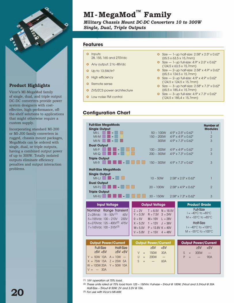
Product HighlightsVicor’s MI-MegaMod family
of single, dual, and triple output
DC-DC converters provide power
system designers with cost-
effective, high-performance, off-
the-shelf solutions to applications
that might otherwise require a
custom supply.
Incorporating standard MI-200
or MI-J00 family converters in
rugged, chassis mount packages,
MegaMods can be ordered with
single, dual, or triple outputs,
having a combined output power
of up to 300W. Totally isolated
outputs eliminate efficiency
penalties and output interaction
problems.
MI-MegaModTM
FamilyMilitary Chassis Mount DC-DC Converters 10 to 300W
Single, Dual, Triple Outputs
20
Inputs: 28, 155, 165 and 270Vdc
Any output: 2 to 48Vdc
Up to 13.5W/in3
High efficiency
Remote sense
ZVS/ZCS power architecture
Low noise FM control
Size — 1- up half-size: 2.58" x 2.5" x 0.62"(65,5 x 63,5 x 15,7mm)
Size — 1- up full-size: 4.9" x 2.5" x 0.62"(124,5 x 63,5 x 15,7mm)
Size — 2- up half-size: 2.58" x 4.9" x 0.62"(65,5 x 124,5 x 15,7mm)
Size — 2- up full-size: 4.9" x 4.9" x 0.62"(124,5 x 124,5 x 15,7mm)
Size — 3- up half-size: 2.58" x 7.3" x 0.62"(65,5 x 185,4 x 15,7mm)
Size — 3- up full-size: 4.9" x 7.3" x 0.62"(124,5 x 185,4 x 15,7mm)
Output Power/Current≥5V <5V
S = 300W —P = — 90A
Output Power/Current≥5V <5V
V = 150W 30AU = 200W —S = — 60A
Output Power/CurrentFull-Size Half-Size≥5V <5V ≥5V <5V
Y = 50W 10A A = 10W —X = 75W 15A Z = 25W 5AW = 100W 20A Y = 50W 10AV = — 30A
Product GradeFull-Size
I = –40°C to +85°CM = –55°C to +85°C
Half-SizeI = –40°C to +100°C
M = –55°C to +100°C
Output Voltage
Z = 2V T = 6.5V N = 18.5VY = 3.3V R = 7.5V 3 = 24V0 = 5V M = 10V L = 28VX = 5.2V 1 = 12V J = 36VW= 5.5V P = 13.8V K = 40VV = 5.8V 2 = 15V 4 = 48V
Input Voltage
Nominal Range Transient2 =28Vdc 18 – 50V (1) 60V5 =155Vdc 100 – 210V 230V6 =270Vdc 125 – 400V(2) 475V7 =165Vdc 100 – 310V(3)
Full-Size MegaMods Number ofSingle Output Modules
MI-L – 50 – 100W 4.9" x 2.5" x 0.62" 1MI-M – 150 – 200W 4.9" x 4.9" x 0.62" 2MI-N – 300W 4.9" x 7.3" x 0.62" 3
Dual OutputMI-P – 100 – 200W 4.9" x 4.9" x 0.62" 2MI-Q – 200 – 300W 4.9" x 7.3" x 0.62" 3
Triple OutputMI-R – 150 – 300W 4.9" x 7.3" x 0.62" 3
Half-Size MegaModsSingle Output
MI-LJ – 10 – 50W 2.58" x 2.5" x 0.62" 1
Dual OutputMI-PJ – 20 – 100W 2.58" x 4.9" x 0.62" 2
Triple OutputMI-RJ – 30 – 150W 2.58" x 7.3" x 0.62" 3
(1) 16V operation at 75% load.(2) These units rated at 75% load from 125 – 150Vin: Full-size – 5Vout @ 100W; 2Vout and 3.3Vout @ 30A
Half-Size – 5Vout @ 50W; 2V and 3.3V @ 10A.(3) For use with Vicor’s MI-AIM
Features
Configuration Chart
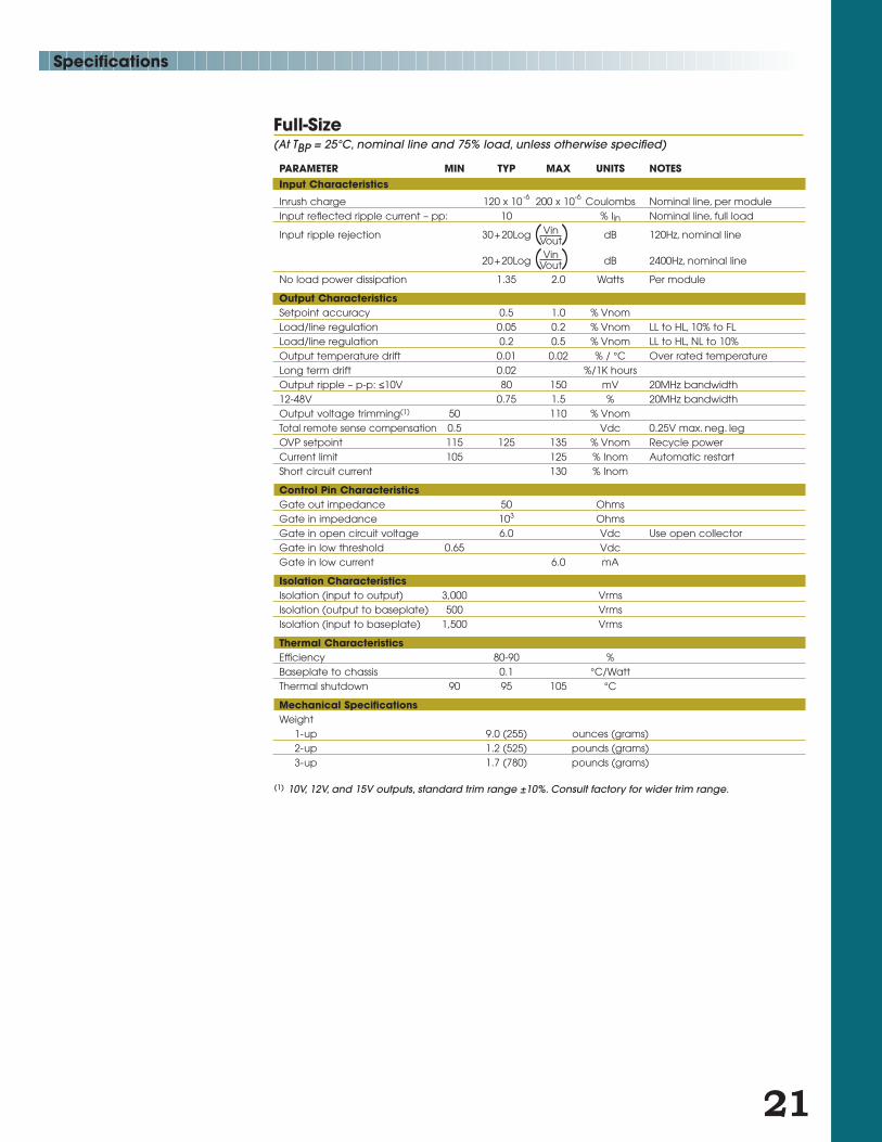
Full-Size(At TBP = 25°C, nominal line and 75% load, unless otherwise specified)
PARAMETER MIN TYP MAX UNITS NOTESInput Characteristics
Inrush charge 120 x 10-6 200 x 10-6 Coulombs Nominal line, per moduleInput reflected ripple current – pp: 10 % Iin Nominal line, full load
Input ripple rejection 30+20Log dB 120Hz, nominal line
20+20Log dB 2400Hz, nominal line
No load power dissipation 1.35 2.0 Watts Per module
Output CharacteristicsSetpoint accuracy 0.5 1.0 % VnomLoad/line regulation 0.05 0.2 % Vnom LL to HL, 10% to FLLoad/line regulation 0.2 0.5 % Vnom LL to HL, NL to 10%Output temperature drift 0.01 0.02 % / °C Over rated temperatureLong term drift 0.02 %/1K hoursOutput ripple – p-p: ≤10V 80 150 mV 20MHz bandwidth12-48V 0.75 1.5 % 20MHz bandwidthOutput voltage trimming(1) 50 110 % VnomTotal remote sense compensation 0.5 Vdc 0.25V max. neg. legOVP setpoint 115 125 135 % Vnom Recycle power Current limit 105 125 % Inom Automatic restartShort circuit current 130 % Inom
Control Pin CharacteristicsGate out impedance 50 OhmsGate in impedance 103 OhmsGate in open circuit voltage 6.0 Vdc Use open collectorGate in low threshold 0.65 VdcGate in low current 6.0 mA
Isolation CharacteristicsIsolation (input to output) 3,000 VrmsIsolation (output to baseplate) 500 VrmsIsolation (input to baseplate) 1,500 Vrms
Thermal CharacteristicsEfficiency 80-90 %Baseplate to chassis 0.1 °C/WattThermal shutdown 90 95 105 °C
Mechanical SpecificationsWeight
1-up 9.0 (255) ounces (grams)2-up 1.2 (525) pounds (grams)3-up 1.7 (780) pounds (grams)
( Vin )Vout
( Vin )Vout
(1) 10V, 12V, and 15V outputs, standard trim range ±10%. Consult factory for wider trim range.
21
Specifications
Specifications
22
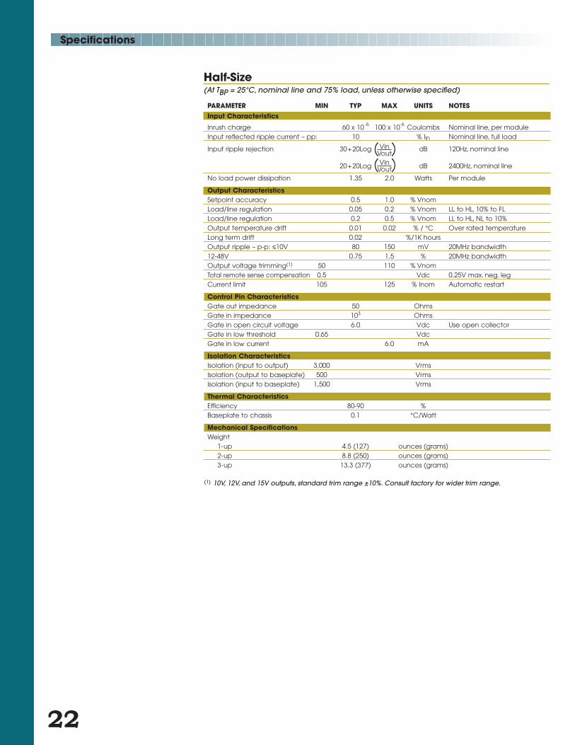
Half-Size(At TBP = 25°C, nominal line and 75% load, unless otherwise specified)
PARAMETER MIN TYP MAX UNITS NOTESInput Characteristics
Inrush charge 60 x 10-6 100 x 10-6 Coulombs Nominal line, per moduleInput reflected ripple current – pp: 10 % Iin Nominal line, full load
Input ripple rejection 30+20Log dB 120Hz, nominal line
20+20Log dB 2400Hz, nominal line
No load power dissipation 1.35 2.0 Watts Per module
Output CharacteristicsSetpoint accuracy 0.5 1.0 % VnomLoad/line regulation 0.05 0.2 % Vnom LL to HL, 10% to FLLoad/line regulation 0.2 0.5 % Vnom LL to HL, NL to 10%Output temperature drift 0.01 0.02 % / °C Over rated temperatureLong term drift 0.02 %/1K hoursOutput ripple – p-p: ≤10V 80 150 mV 20MHz bandwidth12-48V 0.75 1.5 % 20MHz bandwidthOutput voltage trimming(1) 50 110 % VnomTotal remote sense compensation 0.5 Vdc 0.25V max. neg. legCurrent limit 105 125 % Inom Automatic restart
Control Pin CharacteristicsGate out impedance 50 OhmsGate in impedance 103 OhmsGate in open circuit voltage 6.0 Vdc Use open collectorGate in low threshold 0.65 VdcGate in low current 6.0 mA
Isolation CharacteristicsIsolation (input to output) 3,000 VrmsIsolation (output to baseplate) 500 VrmsIsolation (input to baseplate) 1,500 Vrms
Thermal CharacteristicsEfficiency 80-90 %Baseplate to chassis 0.1 °C/Watt
Mechanical SpecificationsWeight
1-up 4.5 (127) ounces (grams)2-up 8.8 (250) ounces (grams)3-up 13.3 (377) ounces (grams)
( Vin )Vout
( Vin )Vout
(1) 10V, 12V, and 15V outputs, standard trim range ±10%. Consult factory for wider trim range.

Mechanical Drawing
L- and LJ-Series
Inputs
Side view (all models)
Outputs
R- and RJ-Series Q-Series N-Series
2.58(65,5)
HALF-SIZEMODULE:
SER. NO.
4.90(124,5) TYP. 0.53
(13,5)TYP.
1.60(40,6)
3.20(81,3)
ø.150 (ø3,81) THRUC'BORE ø.250 (ø6,35)X .170 (4,32) DEEP
B
D
A
C
E4
1
3
2
TOP VIEW 0.62(16.0) TYP.
5.52
(140,2)TYP.
2.76(70,1)
TYP.
0.19(4,8) TYP.
2.18
(55,4)
0.16
(4,1)
2.50(63,5)
TYP.DC-DC CONVERTER
MEGA MODULE
Baseplate (TYP.)
HALF-SIZEMODULE:
HALF-SIZEMODULE:
C
A
D
B
E
2
3
1
4 E
B
D
A
C
K
G
J
F
H
1
3
2
4
5
6
TOP VIEW
DC-DC CONVERTER
TMMEGA MODULE
5
0.25(6,4) TYP.
2.26(57,4)
2.26(57,4)
0.19(4,8)
4.90(124,5) TYP.
C
A
D
B
E
1
3
2
4
4
H
F
J
G
K
E
B
D
A
C
B
A
C
D
E
P
M
L
N
Q
J
G
K
H
F
8
7
1
2
33
2
1
7
8
4
5
6
TOP VIEW
7
6.94
(176,3)
2.26
(57,4)
2.26
(57,4)
0.19
(4,8)
7.32(185,9)
TYP.
DC-DC CONVERTER
MEGA MODULE
P- and PJ-Series M-Series M-Series P- and PJ-Series
N-Series Q-Series R- and RJ-Series
L- and LJ-Series
23
Inputs
1 –Input 5 Gate Out #22 Gate Out #1 6 Gate In #23 Gate In #1 7 Gate Out #34 +Input 8 Gate In #3
Outputs
Output #1 Output #2 Output #3A –Output F –Output L –Output B –Sense G –Sense M –SenseC Trim H Trim N TrimD +Sense J +Sense P +SenseE +Output K +Output Q +Output
Mounting InformationUse #6 machine hardware torqued to 5-7 in-lbs.
1-Up
2-Up
3-Up
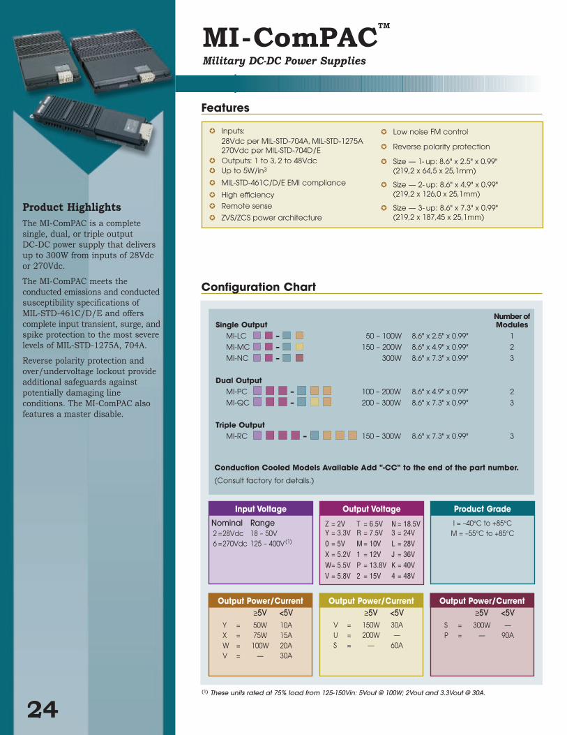
Product HighlightsThe MI-ComPAC is a complete
single, dual, or triple output
DC-DC power supply that delivers
up to 300W from inputs of 28Vdc
or 270Vdc.
The MI-ComPAC meets the
conducted emissions and conducted
susceptibility specifications of
MIL-STD-461C/D/E and offers
complete input transient, surge, and
spike protection to the most severe
levels of MIL-STD-1275A, 704A.
Reverse polarity protection and
over/undervoltage lockout provide
additional safeguards against
potentially damaging line
conditions. The MI-ComPAC also
features a master disable.
24
Inputs: 28Vdc per MIL-STD-704A, MIL-STD-1275A270Vdc per MIL-STD-704D/E
Outputs: 1 to 3, 2 to 48Vdc Up to 5W/in3
MIL-STD-461C/D/E EMI compliance
High efficiency
Remote sense
ZVS/ZCS power architecture
Low noise FM control
Reverse polarity protection
Size — 1- up: 8.6" x 2.5" x 0.99"(219,2 x 64,5 x 25,1mm)
Size — 2- up: 8.6" x 4.9" x 0.99"(219,2 x 126,0 x 25,1mm)
Size — 3- up: 8.6" x 7.3" x 0.99"(219,2 x 187,45 x 25,1mm)
Output Power/Current≥5V <5V
S = 300W —P = — 90A
Output Power/Current≥5V <5V
V = 150W 30AU = 200W —S = — 60A
Output Power/Current≥5V <5V
Y = 50W 10AX = 75W 15AW = 100W 20AV = — 30A
Product Grade
I = –40°C to +85°CM = –55°C to +85°C
Input Voltage
Nominal Range2 =28Vdc 18 – 50V6 =270Vdc 125 – 400V(1)
Number ofSingle Output Modules
MI-LC – 50 – 100W 8.6" x 2.5" x 0.99" 1
MI-MC – 150 – 200W 8.6" x 4.9" x 0.99" 2
MI-NC – 300W 8.6" x 7.3" x 0.99" 3
Dual OutputMI-PC – 100 – 200W 8.6" x 4.9" x 0.99" 2
MI-QC – 200 – 300W 8.6" x 7.3" x 0.99" 3
Triple OutputMI-RC – 150 – 300W 8.6" x 7.3" x 0.99" 3
MI-ComPACTM
Military DC-DC Power Supplies
(1) These units rated at 75% load from 125-150Vin: 5Vout @ 100W; 2Vout and 3.3Vout @ 30A.
Features
Configuration Chart
Output Voltage
Z = 2V T = 6.5V N = 18.5VY = 3.3V R = 7.5V 3 = 24V0 = 5V M = 10V L = 28VX = 5.2V 1 = 12V J = 36VW= 5.5V P = 13.8V K = 40VV = 5.8V 2 = 15V 4 = 48V
Conduction Cooled Models Available Add "-CC" to the end of the part number.
(Consult factory for details.)
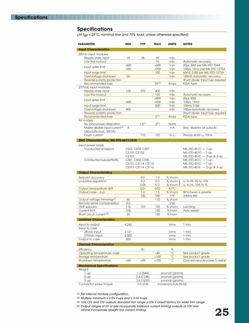
Specifications(At TBP = 25°C, nominal line and 75% load, unless otherwise specified)
Specifications
PARAMETER MIN TYP MAX UNITS NOTES
Input Characteristics
28Vdc input modulesSteady state input 18 28 50 VdcLow line lockout 16 Vdc Automatic recovery
Input spike limit -600 +600 Vdc 20µs, 50Ω per MIL-STD-704A-250 +250 Vdc 100µs, 15mJ per MIL-STD-1275A
Input surge limit 100 Vdc 60mS, 0.5Ω per MIL-STD-1275AOvervoltage shutdown 50 Vdc 100mS automatic recoveryReverse polarity protection Shunt diode: input fuse requiredRecommended fuse 10(1) Amps F03A type
270Vdc input modules Steady state input 125 270 400 VdcLow line lockout 125 Vdc Automatic recovery
Input spike limit +800 Vdc 20µs, 50Ω-600 +600 Vdc 100µs, 15mJ
Input surge limit 500 Vdc 100ms, 0.5ΩOvervoltage shutdown 400 Vdc 100µs automatic recoveryReverse polarity protection Shunt diode: input fuse requiredRecommended fuse 2(1) Amps F03A type
All modelsNo load power dissipation 1.5(1) 2(1) WattsMaster disable input current(2) 4 mA Sink; disables all outputs(Absolute max., 20mA)Inrush current 110 125 %, Iin Steady state Iin, 10ms
EMC Characteristics; MIL-STD-461C/D/E
Input power leadsConducted emissions CE01, CE03, CE07 MIL-STD-461C — 1-up
CE101, CE102 MIL-STD-461D — 1-upCE101 MIL-STD-461E — 2-up & 3-up
Conducted susceptibility CS01, CS02, CS06 MIL-STD-461C — 1-upCS101, CS114, CS116 MIL-STD-461D — 1-upCS101, CS114, CS116 MIL-STD-461E — 2-up & 3-up
Output Characteristics
Setpoint accuracy 0.5 1.0 % VnomLoad/line regulation 0.2 0.5 % Vnom LL to HL, NL to 10%
0.05 0.2 % Vnom LL to HL, 10% to FLOutput temperature drift 0.01 0.02 %/°COutput noise – p-p 1.0 1.5 % Vnom Whichever is greater
100 150 mV 20MHz BWOutput voltage trimming(3) 50 110 % VnomRemote sense compensation 0.5 VdcOVP setpoint 115 125 135 % Vnom LatchingCurrent limit 105 125 % Inom Auto restartShort circuit current (4) 20 130 % Inom
Isolation Characteristics
Input to output 4,242 Vrms 1 min.Input to case
28Vdc input 2,121 Vrms 1 min.270Vdc input 2,500 Vrms 1 min.
Output to case 500 Vrms 1 min.
Thermal Characteristics
Efficiency 81 %Operating temperature, case +85 ˚C See product gradeStorage temperature +100 ˚C See product grade Shutdown temperature +90 +95 +105 ˚C Cool and recycle power to restart
Mechanical SpecificationsWeight
1-up 1.2 (544) pounds (grams)2-up 2.4 (1248) pounds (grams)3-up 3.6 (1633) pounds (grams)
Connector screw torque 3.5 (0.4) inches-pounds (N-M)
25
(1) Per internal module configuration.(2) Multiply minimum x 2 for 2-ups and x 3 for 3-ups.(3) 10V, 12V, and 15V outputs, standard trim range ±10%. Consult factory for wider trim range.(4) Output ranges of 5V or less incorporate foldback current limiting, outputs of 10V and
above incorporate straight line current limiting.
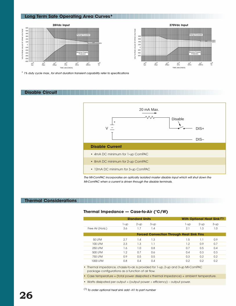
Long Term Safe Operating Area Curves*
Disable Circuit
Thermal Considerations
26
20 mA Max.
Disable
DIS+
DIS–
+
V
VO
LTS
-PE
AK
VA
LUE
OF
SP
IKE
VO
LTA
GE
TIME (SECONDS)
1s010
100ms-110
10ms-210
1ms-310
100µs-410
10µs-510
1µs-610
-600
-500
-400
-300
-200
-100
0
100
200
300
400
500
600
Ratings Exceeded
Reverse PolarityProtection
50VOVP
VO
LTS
-PE
AK
VA
LUE
OF
SP
IKE
VO
LTA
GE
TIME (SECONDS)
1s010
100ms-110
10ms-210
1ms-310
100µs-410
10µs-510
1µs-610
600
400
200
0
200
400
600
800Ratings Exceeded
Reverse PolarityProtection
500VOVP 400V
28Vdc Input 270Vdc Input
* 1% duty cycle max., for short duration transient capability refer to specifications
• Thermal impedance, chassis-to-air, is provided for 1-up, 2-up and 3-up MI-ComPAC package configurations as a function of air flow.
• Case temperature = (total power dissipated x thermal impedance) + ambient temperature.
• Watts dissipated per output = (output power ÷ efficiency) – output power.
(1) To order optional heat sink add –H1 to part number
Thermal Impedance — Case-to-Air (°C/W)
Standard Units With Optional Heat Sink(1)
1-up 2-up 3-up 1-up 2-up 3-up
Free Air (Horiz.) 3.6 1.7 1.4 2.1 1.3 1.0
Forced Convection Through Heat Sink Fins
50 LFM 2.7 1.4 1.3 1.5 1.1 0.9
100 LFM 2.3 1.3 1.1 1.2 0.9 0.7
250 LFM 1.6 1.0 0.8 0.7 0.5 0.4
500 LFM 1.2 0.7 0.6 0.4 0.3 0.3
750 LFM 0.9 0.5 0.5 0.3 0.2 0.2
1000 LFM 0.8 0.4 0.4 0.2 0.2 0.2
Disable Current
• 4mA DC minimum for 1-up ComPAC
• 8mA DC minimum for 2-up ComPAC
• 12mA DC minimum for 3-up ComPAC
The MI-ComPAC incorporates an optically isolated master disable input which will shut down the
MI-ComPAC when a current is driven through the disable terminals.

12
ø0.150 ± 0.005 THRU 6 PLACES(ø3,81 ± 0,13)
12
34
5
4.96(126,0)
4.42(112,3)
7.380(187,45)
0.18(4,6)
6.00(152,4)
2.76(70,1)
7.00(177,8)
2.288(58,12)
2.420(61,47)
0.20(5,1)
0.19(4,8)
A
E
D
C
B
A
E
D
C
B
A
E
D
C
B
0.41 (10,41)
6.95 (176,53)
6.37 (161,80)5.98 (151,89)5.59 (141,99)5.25 (133,35)
4.53 (115,06)
3.95 (100,33)3.56 (90,42)3.17 (80,52)2.83 (71,88)
2.11 (53,59)
1.53 (38,86)1.14 (28,96)0.75 (19,05)
0
#10-32 STUD 2 PLACES
#8-32 STUD 6 PLACES
0.25 TYP
D
C
B
A
E
D
C
B
AA
E
D
C
B
E
#10-32 STUD 2 PLACES
#8-32 STUD 2 PLACES
OU
TP
UT
1O
UT
PU
T 2
OU
TP
UT
1
OU
TP
UT
1O
UT
PU
T 2
OU
TP
UT
3
0.41 (10,41)
2.11 (53,59)
1.53 (38,86)1.14 (28,96)0.75 (19,05)1
2
ø0.150 ± 0.005 THRU 4 PLACES(ø3,81 ± 0,13)
0
12
34
5
2.156(54,76)
0.18(4,6)
2.76
(70,1)
6.00(152,4)
0.9123,1)
2.54
(64,5)
0.20(5,1)
0.19(4,8)
0.20(5,1)
E
D
C
B
A
0.25 TYP #8-32 STUD 2 PLACES
OU
TP
UT
1(
0.41 (10,41)
4.53 (115,06)
3.95 (100,33)3.56 (90,42)3.17 (80,52)2.83 (71,88)
2.11 (53,59)
1.53 (38,86)1.14 (28,96)0.75 (19,05)
12
ø0.150 ± 0.005 THRU 5 PLACES(ø3,81 ± 0,13)
#10-32 STUD 2 PLACES
12
34
5
3.58
(90,9)
3.04(77,2)
4.96
(126,0)
4.562(115,87)
0.18(4,6)
6.00(152,4)
2.76(70,1)
2.281(57,94)
0.20(5,1)
0.19(4,8)
#8-32 STUD 4 PLACES
A
E
D
C
B
A
E
D
C
B
4.
0
0.25 TYP
A
E
D
C
BO
UT
PU
T 1
OU
TP
UT
2
OU
TP
UT
1
OPTIONAL HEATSINK (H1)
STANDARD UNITS
1.12(28,4)
1.37
(34,80)
0.99(25,15)
0.5(12,57)
0.41(10,4)
9.25 ±.120
(235,0 ±3,05)
8.63 ±.025
(219,2±,64)
0.5(12,57)
Measure case temperature on this surface.
Mechanical Drawing
Inputs Outputs
MI-MC MI-PC
MI-NC MI-QC MI-RC
27
Inputs
1 –Ground 4 Disable–2 –Input 5 Disable+3 +Input
Outputs
Output #1 Output #2 Output #3A +Output A +Output A +Output B +Sense B +Sense B +SenseC Trim C Trim C TrimD –Sense D –Sense D –SenseE –Output E –Output E –Output
1-Up
2-Up
3-Up
MI-LC

28
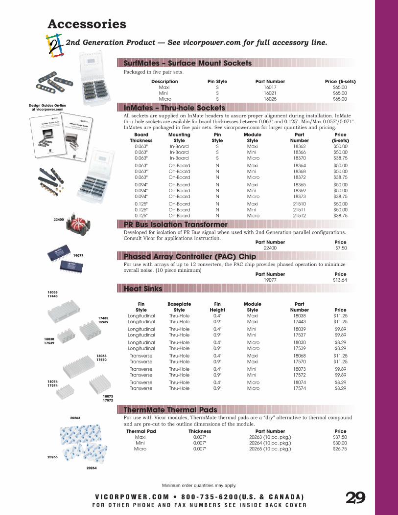
Accessories1st Generation Product — See vicorpower.com for full accessory line.
Sockets are available for all Vicor 1st Generation modules and are intended for applications requiring ease of module installation or removal. Vicor modules have nine pins; seven of which are 0.040" and two are 0.080".
Pin Size Finish Part Number Price0.040" Electro-tin 01827 $0.420.080" Electro-tin 01828 $0.85
Sockets
For mechanical mounting of 1st Generation modules. Also provides grounding of the module from the baseplate to the printed circuit board. (Sold individually)
Description Part Number Price0.525" Long., 0.25" Hex 10692-01 $1.07
Module Standoffs
Output inductors may be used to reduce differential output noise by approximately 20dB.
Inductance(@ max. A) DC Current (max.) Part Number Price130-150 ηH 40A 05298 $3.21
Inductors, Differential Mode
Common-mode inductors provide a high level of attenuation of common-mode currents.
Inductance/ DC Current/Winding Resistance Part Number Price1000 µH 12A/6.5 mΩ 02134 $14.233000 µH 7A/18 mΩ 02133 $14.23
Inductors, Common Mode
For EMI/RFI considerations, Y capacitors should be used with any of Vicor’s DC-DC converter modules.
Description Part Number Price“Y” Cap., 1500 pF 00770 $1.71“Y” Cap., 4700 pF 01000 $1.33
Capacitors, Y-Type
For use with Vicor modules, ThermMate thermal pads are a “dry” alternative to thermal compound
and are pre-cut to the outline dimensions of the module.
Thermal Pad Thickness Part Number PriceFull-Size 0.007" 20266 (10 pc. pkg.) $37.50Half-Size 0.007" 20267 (10 pc. pkg.) $30.00
ThermMate Thermal Pads
Description Fin Height Part Number PriceFull-Size (Longitudinal) 0.90" 02111 $8.02Full-Size (Longitudinal) 0.70" 06927 $8.02Full-Size (Longitudinal) 1.45" 02092 $10.70
Full-Size (Transverse) 0.90" 02113 $8.02Full-Size (Transverse) 0.70" 04431 $8.02Full-Size (Transverse) 0.40" 02112 $8.02
Half-Size (Longitudinal) 0.90" 04306 $5.35Half-Size (Transverse) 0.90" 04307 $5.35Half-Size (Transverse) 0.40" 05738 $5.35
Heat Sinks
Solid tantalum capacitor used to reduce output ripple.
Description Part Number Price270 µF/10V 24252 $5.50120 µF/20V 24253 $5.5068 µF/30V 24254 $5.5027 µF/50V 24255 $5.50
Capacitors, Tantalum
01828
01827
10692-01
05298
02134
02133
00770, 01000
20266
20267
02111
06927
02092
02113
04431
02112
0430605738
04307
V I C O R P O W E R . C O M • 8 0 0 - 7 3 5 - 6 2 0 0 ( U.S. & C A N A D A )F O R O T H E R P H O N E A N D F A X N U M B E R S S E E I N S I D E B A C K C O V E R
Minimum order quantities may apply.
24252 — 24255
For use with Vicor modules, ThermMate thermal pads are a “dry” alternative to thermal compound
and are pre-cut to the outline dimensions of the module.
Thermal Pad Thickness Part Number PriceMaxi 0.007" 20263 (10 pc. pkg.) $37.50Mini 0.007" 20264 (10 pc. pkg.) $30.00
Micro 0.007" 20265 (10 pc. pkg.) $26.75
Accessories2nd Generation Product — See vicorpower.com for full accessory line.
Packaged in five pair sets.
Description Pin Style Part Number Price (5-sets)Maxi S 16017 $65.00Mini S 16021 $65.00Micro S 16025 $65.00
SurfMates – Surface Mount Sockets
All sockets are supplied on InMate headers to assure proper alignment during installation. InMate thru-hole sockets are available for board thicknesses between 0.063" and 0.125". Min/Max 0.055"/0.071".InMates are packaged in five pair sets. See vicorpower.com for larger quantities and pricing.
Board Mounting Pin Module Part PriceThickness Style Style Style Number (5-sets)
0.063" In-Board S Maxi 18362 $50.000.063" In-Board S Mini 18366 $50.000.063" In-Board S Micro 18370 $38.75
0.063" On-Board N Maxi 18364 $50.000.063" On-Board N Mini 18368 $50.000.063" On-Board N Micro 18372 $38.75
0.094" On-Board N Maxi 18365 $50.000.094" On-Board N Mini 18369 $50.000.094" On-Board N Micro 18373 $38.75
0.125" On-Board N Maxi 21510 $50.000.125" On-Board N Mini 21511 $50.000.125" On-Board N Micro 21512 $38.75
InMates – Thru-hole Sockets
1803817443
V I C O R P O W E R . C O M • 8 0 0 - 7 3 5 - 6 2 0 0 ( U.S. & C A N A D A )F O R O T H E R P H O N E A N D F A X N U M B E R S S E E I N S I D E B A C K C O V E R
Minimum order quantities may apply.
Developed for isolation of PR Bus signal when used with 2nd Generation parallel configurations.Consult Vicor for applications instruction.
Part Number Price22400 $7.50
PR Bus Isolation Transformer
For use with arrays of up to 12 converters, the PAC chip provides phased operation to minimize overall noise. (10 piece minimum)
Part Number Price19077 $13.64
Phased Array Controller (PAC) Chip
Fin Baseplate Fin Module Part Style Style Height Style Number Price
Longitudinal Thru-Hole 0.4" Maxi 18038 $11.25Longitudinal Thru-Hole 0.9" Maxi 17443 $11.25
Longitudinal Thru-Hole 0.4" Mini 18039 $9.89Longitudinal Thru-Hole 0.9" Mini 17537 $9.89
Longitudinal Thru-Hole 0.4" Micro 18030 $8.29Longitudinal Thru-Hole 0.9" Micro 17539 $8.29
Transverse Thru-Hole 0.4" Maxi 18068 $11.25Transverse Thru-Hole 0.9" Maxi 17570 $11.25
Transverse Thru-Hole 0.4" Mini 18073 $9.89Transverse Thru-Hole 0.9" Mini 17572 $9.89
Transverse Thru-Hole 0.4" Micro 18074 $8.29Transverse Thru-Hole 0.9" Micro 17574 $8.29
Heat Sinks
ThermMate Thermal Pads20263
29
20265
20264
1748515989
1803017539
1806817570
1807317572
1807417574
19077
22400
Design Guides On-line at vicorpower.com

30
Environmental Stress Screening & MTBF
Every military module undergoes extensive post-production environmental stress
screening (ESS) before shipment to verify compliance with Vicor's high quality and
performance standards and to eliminate early life failures. To ensure the most effective
routine for precipitating module failures, Vicor continually evaluates its ESS program
and makes appropriate changes as new data becomes available or as product improvements
occur. After burn-in and temperature cycling, each module undergoes final electrical
testing over the specified temperature range. The program is outlined below.
1st Generation Module Screening I-Grade M-GradeOperating temperature MI-200 -40°C to +85°C -55°C to +85°C
MI-J00 -40°C to +100°C -55°C to +100°C
Storage temperature MI-200 -55°C to +100°C -65°C to +100°C
MI-J00 -55°C to +125°C -65°C to +125°C
Temperature cycling 3°C–4°C per minute 48 hours, 48 hours,nominal chamber rate of change, 15 minute 12–16 cycles, 12–16 cycles,dwell time -55°C to +100°C -65°C to +100°C
Ambient test at 25°C Yes Yes
Power cycling burn-in power on 10 minute,off 15 minute; module temperature cycling 12 hours, 96 hours35°C to 80°C; load to 50% or 100W; module 25 cycles 200 cyclesoutput continuously monitored while enabled
Functional and parametric ATE tests at -40°C/+80°C -55°C/+80°Clow/high temperature.
Hi-Pot test Yes Yes
Visual inspection before packing intoYes YesESD containers
Test data vicorpower.com vicorpower.com
2nd Generation Module Screening H-Grade M-Grade
Operating temperature -40°C to +100°C -55°C to +100°C
Storage temperature -55°C to +125°C -65°C to +125°C
Temperature cycling 3°C–5°C per minutenominal chamber rate of change, 15 minute 8 cycles, 16 cycles,dwell time -55°C to +125°C -65°C to +125°C
Ambient test at 25°C Yes Yes
Power cycling burn-inPower on 10 minutes, off 15 minutes; 12 hours, 24 hoursModule temperature cycling 35°C to 80°C; 28 cycles 56 cyclesload up to 125W; module output continuouslymonitored while enabled.
Functional and parametric ATE tests at -40°C to +80°C -55°C to +80°Clow/high temperature.
Hi-Pot test Yes Yes
Visual inspection before packing intoYes YesESD containers
Test data vicorpower.com vicorpower.com

31
Because operating temperature
is one of the most important factors in
determining overall module reliability, it is
imperative that the user's system design allow for
efficient heat transfer from the baseplate to system
ambient. A 10°C decrease in baseplate temperature can
increase MTBF by over 50%. Due to patented zero-voltage/zero-current switching
topology, Vicor converters are highly efficient compared to those with more traditional
topologies. High efficiency translates into both smaller size and lower temperature
rises. To minimize thermal impedance, all major power dissipating components are
mounted directly to the baseplate.
Below are representative calculated MTBF values per MIL-HDBK-217F. Vicor utilizes
the RelCalc program for MTBF calculations using actual stress ratios, temperatures,
and component qualities. If you require information about a specific model, contact
Vicor with the model number, expected baseplate temperature, and operating
environment to obtain an individually prepared report.
MTBF
2nd Generation Modules MTBF in 1,000 HoursModel No. Baseplate Temp. G.B. G.F. A.I.C. N.S.V300C12M150AL 25°C 3,343 1,671 1,003 986
(Micro) 50°C 2,675 1,337 802 788
65°C 2,173 1,086 652 641
V300B15M250AL 25°C 3,061 1,530 918 903
(Mini) 50°C 2,449 1,224 734 722
65°C 1,990 995 597 587
V300A28M500AL 25°C 2,709 1,354 812 799
(Maxi) 50°C 2,449 1,083 650 639
65°C 1,990 880 528 519
1st Generation Modules MTBF in 1,000 HoursModel No. Baseplate Temp. G.B. G.F. A.I.C. N.S.MI-J60-MY 25°C 2,871 1,435 861 846
50°C 2,296 1,148 689 677
65°C 1,866 933 559 550
MI-260-MW 25°C 2,478 1,239 743 731
50°C 1,982 991 594 584
65°C 1,611 805 483 475
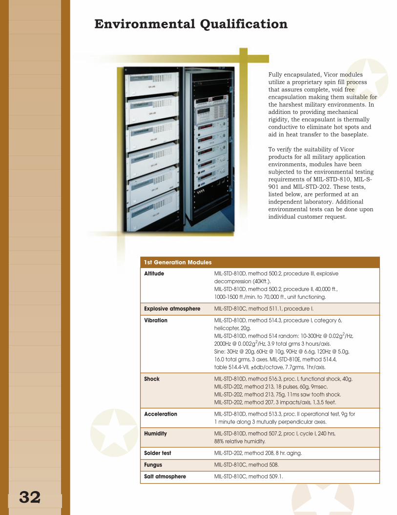
Fully encapsulated, Vicor modules
utilize a proprietary spin fill process
that assures complete, void free
encapsulation making them suitable for
the harshest military environments. In
addition to providing mechanical
rigidity, the encapsulant is thermally
conductive to eliminate hot spots and
aid in heat transfer to the baseplate.
To verify the suitability of Vicor
products for all military application
environments, modules have been
subjected to the environmental testing
requirements of MIL-STD-810, MIL-S-
901 and MIL-STD-202. These tests,
listed below, are performed at an
independent laboratory. Additional
environmental tests can be done upon
individual customer request.
32
Environmental Qualification
1st Generation Modules
Altitude MIL-STD-810D, method 500.2, procedure III, explosive decompression (40Kft.).MIL-STD-810D, method 500.2, procedure II, 40,000 ft.,1000-1500 ft./min. to 70,000 ft., unit functioning.
Explosive atmosphere MIL-STD-810C, method 511.1, procedure I.
Vibration MIL-STD-810D, method 514.3, procedure I, category 6,helicopter, 20g.MIL-STD-810D, method 514 random: 10-300Hz @ 0.02g2/Hz,2000Hz @ 0.002g2/Hz, 3.9 total grms 3 hours/axis.Sine: 30Hz @ 20g, 60Hz @ 10g, 90Hz @ 6.6g, 120Hz @ 5.0g,16.0 total grms, 3 axes. MIL-STD-810E, method 514.4,table 514.4-VII, ±6db/octave, 7.7grms, 1hr/axis.
Shock MIL-STD-810D, method 516.3, proc. I, functional shock, 40g.MIL-STD-202, method 213, 18 pulses, 60g, 9msec.MIL-STD-202, method 213, 75g, 11ms saw tooth shock.MIL-STD-202, method 207, 3 impacts/axis, 1,3,5 feet.
Acceleration MIL-STD-810D, method 513.3, proc. II operational test, 9g for 1 minute along 3 mutually perpendicular axes.
Humidity MIL-STD-810D, method 507.2, proc I, cycle I, 240 hrs,88% relative humidity.
Solder test MIL-STD-202, method 208, 8 hr. aging.
Fungus MIL-STD-810C, method 508.
Salt atmosphere MIL-STD-810C, method 509.1.
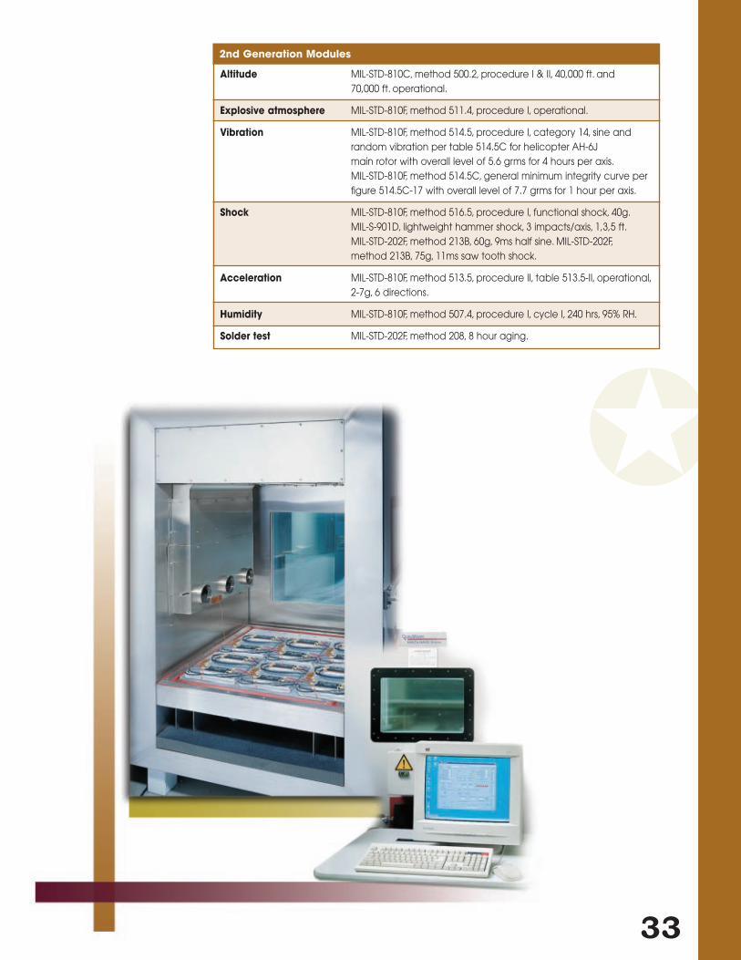
33
Altitude MIL-STD-810C, method 500.2, procedure I & II, 40,000 ft. and 70,000 ft. operational.
Explosive atmosphere MIL-STD-810F, method 511.4, procedure I, operational.
Vibration MIL-STD-810F, method 514.5, procedure I, category 14, sine andrandom vibration per table 514.5C for helicopter AH-6Jmain rotor with overall level of 5.6 grms for 4 hours per axis.MIL-STD-810F, method 514.5C, general minimum integrity curve per figure 514.5C-17 with overall level of 7.7 grms for 1 hour per axis.
Shock MIL-STD-810F, method 516.5, procedure I, functional shock, 40g.MIL-S-901D, lightweight hammer shock, 3 impacts/axis, 1,3,5 ft.MIL-STD-202F, method 213B, 60g, 9ms half sine. MIL-STD-202F,method 213B, 75g, 11ms saw tooth shock.
Acceleration MIL-STD-810F, method 513.5, procedure II, table 513.5-II, operational,2-7g, 6 directions.
Humidity MIL-STD-810F, method 507.4, procedure I, cycle I, 240 hrs, 95% RH.
Solder test MIL-STD-202F, method 208, 8 hour aging.
2nd Generation Modules
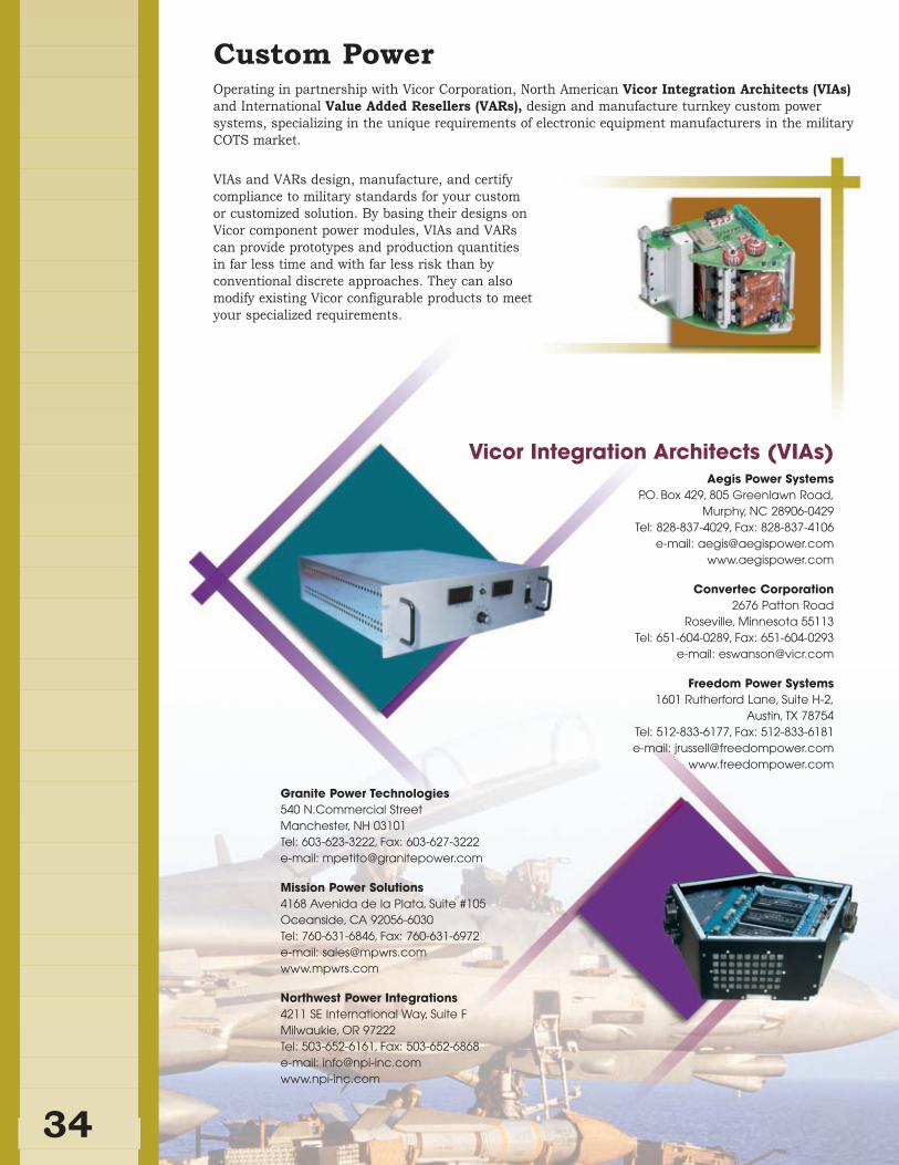
34
Custom PowerOperating in partnership with Vicor Corporation, North American Vicor Integration Architects (VIAs)and International Value Added Resellers (VARs), design and manufacture turnkey custom power
systems, specializing in the unique requirements of electronic equipment manufacturers in the military
COTS market.
VIAs and VARs design, manufacture, and certify
compliance to military standards for your custom
or customized solution. By basing their designs on
Vicor component power modules, VIAs and VARs
can provide prototypes and production quantities
in far less time and with far less risk than by
conventional discrete approaches. They can also
modify existing Vicor configurable products to meet
your specialized requirements.
Aegis Power Systems P.O. Box 429, 805 Greenlawn Road,
Murphy, NC 28906-0429Tel: 828-837-4029, Fax: 828-837-4106
e-mail: [email protected] www.aegispower.com
Convertec Corporation2676 Patton Road
Roseville, Minnesota 55113Tel: 651-604-0289, Fax: 651-604-0293
e-mail: [email protected]
Freedom Power Systems1601 Rutherford Lane, Suite H-2,
Austin, TX 78754Tel: 512-833-6177, Fax: 512-833-6181 e-mail: [email protected]
www.freedompower.com
Vicor Integration Architects (VIAs)
Granite Power Technologies540 N.Commercial StreetManchester, NH 03101Tel: 603-623-3222, Fax: 603-627-3222 e-mail: [email protected]
Mission Power Solutions 4168 Avenida de la Plata, Suite #105Oceanside, CA 92056-6030Tel: 760-631-6846, Fax: 760-631-6972 e-mail: [email protected]
Northwest Power Integrations 4211 SE International Way, Suite F Milwaukie, OR 97222 Tel: 503-652-6161, Fax: 503-652-6868e-mail: [email protected]
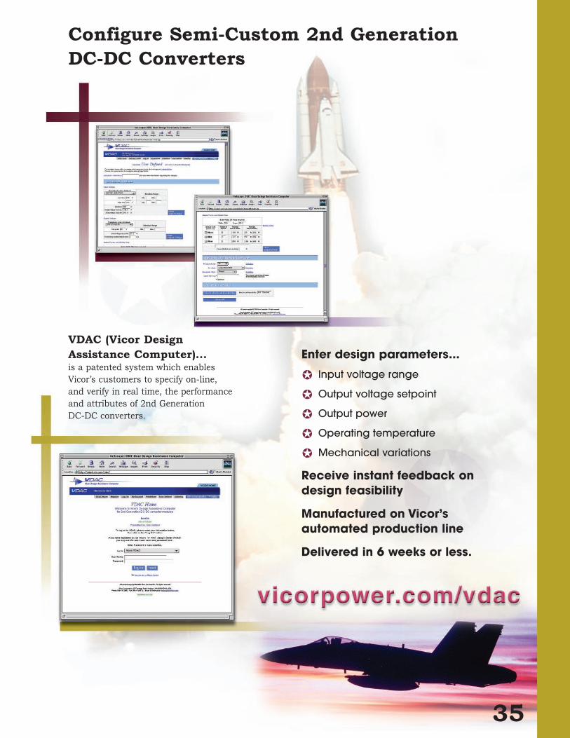
35
Configure Semi-Custom 2nd Generation DC-DC Converters
VDAC (Vicor Design Assistance Computer)...is a patented system which enables
Vicor’s customers to specify on-line,
and verify in real time, the performance
and attributes of 2nd Generation
DC-DC converters.
Enter design parameters...
Input voltage range
Output voltage setpoint
Output power
Operating temperature
Mechanical variations
Receive instant feedback on design feasibility
Manufactured on Vicor’sautomated production line
Delivered in 6 weeks or less.

36
Technical Support
Applications Engineers ...
Evaluate specific customer design issues
and offer a wide range of component-based
power solutions.
Answer technical questions.
(by phone, fax, E-mail, or the Vicor web site)
Assist with component-based power system design.
Support user needs through visits to
customer facilities.
Vicor Express Representatives ...
Provide product price and delivery information.
Help select the most appropriate product
for your application.
Can arrange a visit to your site by a Vicor
applications engineer or sales representative.
Fulfill literature requests.
Process purchase order requirements.
Order status information.
Vicor global offices are fully equipped and staffed with applications engineers and customer
service representatives to provide the product information and technical assistance customers
need concerning Vicor products and power solutions.
USAVicor Corporation (Corporate Headquarters)25 Frontage RoadAndover, MA 01810-5413vicorpower.com
For General InformationTel: 978-470-2900Fax: 978-475-6715
For Technical Support Tel: 800-927-9474Fax: 978-749-3341E-mail: [email protected]
For Sales Support (Vicor Express)In U.S. and Canada: 800-735-6200Fax: 978-475-6715E-mail: [email protected]
Vicor Corporation 377 E. Butterfield RoadLombard, IL 60148Tel: 630-769-8780Fax: 630-769-8782
Vicor Corporation 1601 Rutherford Lane, Suite H-2Austin, TX 78754Tel: 512-833-6177Fax: 512-833-6181
Vicor, Westcor Division 560 Oakmead ParkwaySunnyvale, CA 94085-4022Tel: 408-522-5280Fax: 408-774-5555
Picor CorporationP.O. Box 859Slatersville, RI 02876Tel: 401-235-1100Fax: 401-235-1117picorpower.com
EuropeVicor France6, Parc ArianeBâtiment "Le Mercure"78284 Guyancourt CedexFranceTel: +33-1-3452-18300800 419 419 (in France)Fax: +33-1-3452-2830E-mail: [email protected]
Vicor GermanyAdalperostraße 2985737 Ismaning, GermanyTel: +49-89-962439-00800 018 29 18 (in Germany)Fax: +49-89-962439-39E-mail: [email protected]
Vicor ItalyVia Milanese, 2020099 Sesto S. GiovanniMilano, ItalyTel: +39-02-2247-2326800 899 677 (in Italy)Fax: +39-02-2247-3166E-mail: [email protected]
Vicor U.K.Coliseum Business CentreRiverside Way, CamberleySurrey GU15 3YLEnglandTel: +44-1276-678-222
In UK: 0800-980-8427In Denmark: 80 88 11 41In Norway: 800 11083In Sweden: 020 798236
Fax: +44-1276-681-269E-mail: [email protected]
Asia-PacificVicor Japan Co., Ltd.6F, POLA 3rd Bldg.8-9-5, Nishi-gotandaShinagawa-kuTokyo 141-0031 JapanTel: +81-3-5487-3880Fax: +81-3-5487-3885www.vicr.co.jp
Vicor Hong Kong Rm 511, Tower 1, Silvercord30 Canton RoadTsim Sha TsuiHong Kongwww.vicr.com.cnTel: +852-2956-1782Fax: +852-2956-0782
In Latin America: Call the number below and ask the operator to connect you to 800-735-6200.Argentina: 001-800-200-1111Brazil: 000+8010Mexico: 95-800-462-4240

37
Vicor CorporationVicor designs, manufacturers, and markets modular, high-density power components and
complete configurable power systems used primarily by original equipment manufacturers
(OEMs) in the communications, data processing, industrial control, test equipment,
medical, and defense electronics markets.
Zero-Voltage/Zero-Current Switching TechnologyHigh frequency operation is the key to reducing energy storage elements to a size practical
for implementing power conversion functions in standardized modular packages. The high
efficiency of Vicor’s zero-voltage/zero-current switching topology allows converters to operate
in excess of 1MHz while avoiding energy losses in the switch element — the cause of electrical
and thermal stresses that can undermine the reliability of other high-density converters.
Zero-voltage/zero-current switching consequently results in reliable high-power density,
faster response times, lower conducted and radiated noise, and minimum required
cooling volume.
World Class ManufacturingThe standard design common to all Vicor converters enables the company to use high
speed automated mass manufacturing to dramatically reduce the time and cost of
delivering products that conform to specific customer requirements. Flexible, highly
computer-integrated processes allow Vicor to produce thousands of modules a day in
thousands of variations. The repeatable precision of automated manufacture ensures the
consistent high quality of all our products at the most competitive prices and in the
shortest time possible.
Vicor’s operations at its headquarters in Andover, Massachusetts are registered to the ISO
9001 international quality standard.
Technical SupportVicor Technical Support Centers are fully equipped and staffed with applications engineers
to provide the product information and technical assistance customers need concerning all
of our products and power solutions.
With a worldwide presence, applications engineers support users’ needs through visits to
customer facilities or our applications labs. They are available to answer technical
questions regarding Vicor products and their application in customer products; to assist
with component-based power system design; to evaluate specific customer design issues;
and to offer a wide range of component-based power solutions.
PN 25723 Rev 2 10/02 20M
v i c o r p o w e r. c o m
2ndGeneration


![New [ CS101 ] Introduction to Programming 2015 Spring - Midterm …flywing.co.kr/zokbo/file/KAIST/Common/CS101/2015_Spring... · 2017. 9. 5. · CS101 course. Your program will be](https://img.pdfslide.tips/doc/110x75/60675f28fa04bb6fd234cb3e/new-cs101-introduction-to-programming-2015-spring-midterm-2017-9-5-cs101.jpg)