Embed Size (px)
Citation preview
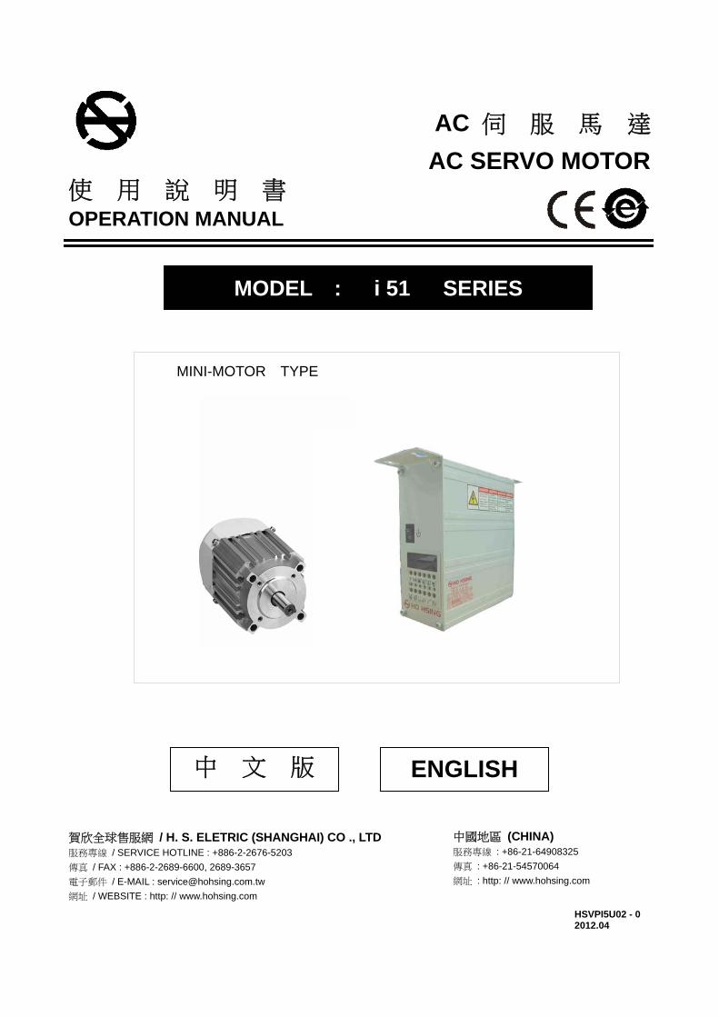
AC 伺 服 馬 達
AC SERVO MOTOR 使 用 說 明 書 OPERATION MANUAL
MODEL : i 51 SERIES
MINI-MOTOR TYPE
中 文 版
賀欣全球售服網 / H. S. ELETRIC (SHANGHAI) CO ., LTD 服務專線 / SERVICE HOTLINE : +886-2-2676-5203
傳真 / FAX : +886-2-2689-6600, 2689-3657
電子郵件 / E-MAIL : [email protected]
網址 / WEBSITE : http: // www.hohsing.com
中國地區 (CHINA) 服務專線 : +86-21-64908325
傳真 : +86-21-54570064
網址 : http: // www.hohsing.com
HSVPI5U02 - 0 2012.04
ENGLISH
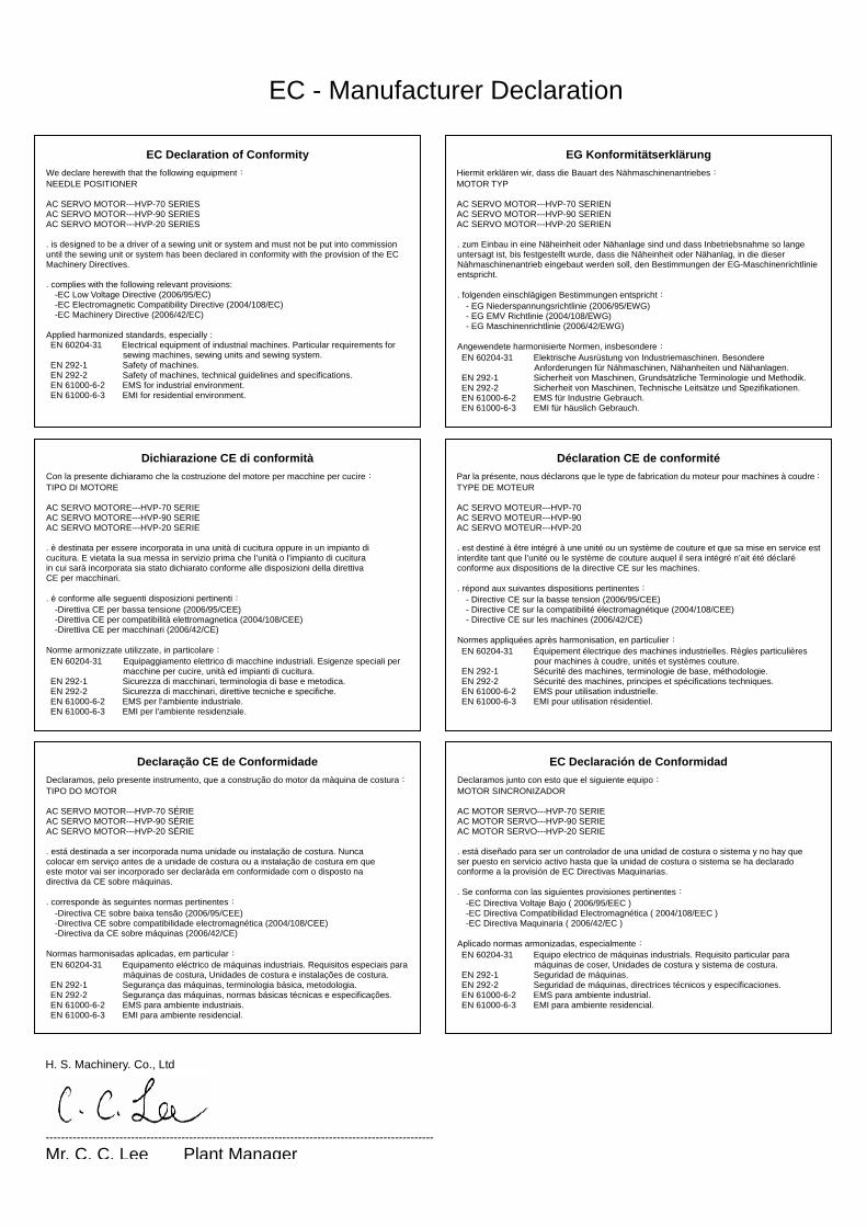
EC - Manufacturer Declaration
EC Declaration of Conformity
We declare herewith that the following equipment: NEEDLE POSITIONER AC SERVO MOTOR---HVP-70 SERIES AC SERVO MOTOR---HVP-90 SERIES AC SERVO MOTOR---HVP-20 SERIES . is designed to be a driver of a sewing unit or system and must not be put into commission until the sewing unit or system has been declared in conformity with the provision of the EC Machinery Directives. . complies with the following relevant provisions: -EC Low Voltage Directive (2006/95/EC) -EC Electromagnetic Compatibility Directive (2004/108/EC) -EC Machinery Directive (2006/42/EC) Applied harmonized standards, especially : EN 60204-31 Electrical equipment of industrial machines. Particular requirements for
sewing machines, sewing units and sewing system. EN 292-1 Safety of machines. EN 292-2 Safety of machines, technical guidelines and specifications. EN 61000-6-2 EMS for industrial environment. EN 61000-6-3 EMI for residential environment.
EG Konformitätserklärung
Hiermit erklären wir, dass die Bauart des Nähmaschinenantriebes: MOTOR TYP AC SERVO MOTOR---HVP-70 SERIEN AC SERVO MOTOR---HVP-90 SERIEN AC SERVO MOTOR---HVP-20 SERIEN . zum Einbau in eine Näheinheit oder Nähanlage sind und dass Inbetriebsnahme so lange untersagt ist, bis festgestellt wurde, dass die Näheinheit oder Nähanlag, in die dieser Nähmaschinenantrieb eingebaut werden soll, den Bestimmungen der EG-Maschinenrichtlinie entspricht. . folgenden einschlägigen Bestimmungen entspricht:
- EG Niederspannungsrichtlinie (2006/95/EWG) - EG EMV Richtlinie (2004/108/EWG) - EG Maschinenrichtlinie (2006/42/EWG)
Angewendete harmonisierte Normen, insbesondere: EN 60204-31 Elektrische Ausrüstung von Industriemaschinen. Besondere
Anforderungen für Nähmaschinen, Nähanheiten und Nähanlagen. EN 292-1 Sicherheit von Maschinen, Grundsätzliche Terminologie und Methodik. EN 292-2 Sicherheit von Maschinen, Technische Leitsätze und Spezifikationen. EN 61000-6-2 EMS für Industrie Gebrauch. EN 61000-6-3 EMI für häuslich Gebrauch.
Dichiarazione CE di conformità
Con la presente dichiaramo che la costruzione del motore per macchine per cucire: TIPO DI MOTORE AC SERVO MOTORE---HVP-70 SERIE AC SERVO MOTORE---HVP-90 SERIE AC SERVO MOTORE---HVP-20 SERIE . è destinata per essere incorporata in una unità di cucitura oppure in un impianto di cucitura. E vietata la sua messa in servizio prima che l’unità o l’impianto di cucitura in cui sarà incorporata sia stato dichiarato conforme alle disposizioni della direttiva CE per macchinari. . è conforme alle seguenti disposizioni pertinenti:
-Direttiva CE per bassa tensione (2006/95/CEE) -Direttiva CE per compatibilità elettromagnetica (2004/108/CEE) -Direttiva CE per macchinari (2006/42/CE)
Norme armonizzate utilizzate, in particolare: EN 60204-31 Equipaggiamento elettrico di macchine industriali. Esigenze speciali per
macchine per cucire, unità ed impianti di cucitura. EN 292-1 Sicurezza di macchinari, terminologia di base e metodica. EN 292-2 Sicurezza di macchinari, direttive tecniche e specifiche. EN 61000-6-2 EMS per l'ambiente industriale. EN 61000-6-3 EMI per l'ambiente residenziale.
Déclaration CE de conformité
Par la présente, nous déclarons que le type de fabrication du moteur pour machines à coudre:TYPE DE MOTEUR AC SERVO MOTEUR---HVP-70 AC SERVO MOTEUR---HVP-90 AC SERVO MOTEUR---HVP-20 . est destiné à être intégré à une unité ou un système de couture et que sa mise en service est interdite tant que l’unité ou le système de couture auquel il sera intégré n’ait été déclaré conforme aux dispositions de la directive CE sur les machines. . répond aux suivantes dispositions pertinentes:
- Directive CE sur la basse tension (2006/95/CEE) - Directive CE sur la compatibilité électromagnétique (2004/108/CEE) - Directive CE sur les machines (2006/42/CE)
Normes appliquées après harmonisation, en particulier: EN 60204-31 Équipement électrique des machines industrielles. Règles particulières
pour machines à coudre, unités et systèmes couture. EN 292-1 Sécurité des machines, terminologie de base, méthodologie. EN 292-2 Sécurité des machines, principes et spécifications techniques. EN 61000-6-2 EMS pour utilisation industrielle. EN 61000-6-3 EMI pour utilisation résidentiel.
Declaração CE de Conformidade
Declaramos, pelo presente instrumento, que a construção do motor da màquina de costura:TIPO DO MOTOR AC SERVO MOTOR---HVP-70 SÉRIE AC SERVO MOTOR---HVP-90 SÉRIE AC SERVO MOTOR---HVP-20 SÉRIE . está destinada a ser incorporada numa unidade ou instalação de costura. Nunca colocar em serviço antes de a unidade de costura ou a instalação de costura em que este motor vai ser incorporado ser declaràda em conformidade com o disposto na directiva da CE sobre máquinas. . corresponde às seguintes normas pertinentes:
-Directiva CE sobre baixa tensão (2006/95/CEE) -Directiva CE sobre compatibilidade electromagnética (2004/108/CEE) -Directiva da CE sobre máquinas (2006/42/CE)
Normas harmonisadas aplicadas, em particular: EN 60204-31 Equipamento eléctrico de máquinas industriais. Requisitos especiais para
máquinas de costura, Unidades de costura e instalações de costura. EN 292-1 Segurança das máquinas, terminologia básica, metodologia. EN 292-2 Segurança das máquinas, normas básicas técnicas e especificações. EN 61000-6-2 EMS para ambiente industriais. EN 61000-6-3 EMI para ambiente residencial.
EC Declaración de Conformidad
Declaramos junto con esto que el siguiente equipo: MOTOR SINCRONIZADOR AC MOTOR SERVO---HVP-70 SERIE AC MOTOR SERVO---HVP-90 SERIE AC MOTOR SERVO---HVP-20 SERIE . está diseñado para ser un controlador de una unidad de costura o sistema y no hay que ser puesto en servicio activo hasta que la unidad de costura o sistema se ha declarado conforme a la provisión de EC Directivas Maquinarias. . Se conforma con las siguientes provisiones pertinentes:
-EC Directiva Voltaje Bajo ( 2006/95/EEC ) -EC Directiva Compatibilidad Electromagnética ( 2004/108/EEC ) -EC Directiva Maquinaria ( 2006/42/EC )
Aplicado normas armonizadas, especialmente: EN 60204-31 Equipo electrico de máquinas industrials. Requisito particular para
máquinas de coser, Unidades de costura y sistema de costura. EN 292-1 Seguridad de máquinas. EN 292-2 Seguridad de máquinas, directrices técnicos y especificaciones. EN 61000-6-2 EMS para ambiente industrial. EN 61000-6-3 EMI para ambiente residencial.
H. S. Machinery. Co., Ltd
---------------------------------------------------------------------------------------------------- Mr. C. C. Lee Plant Manager
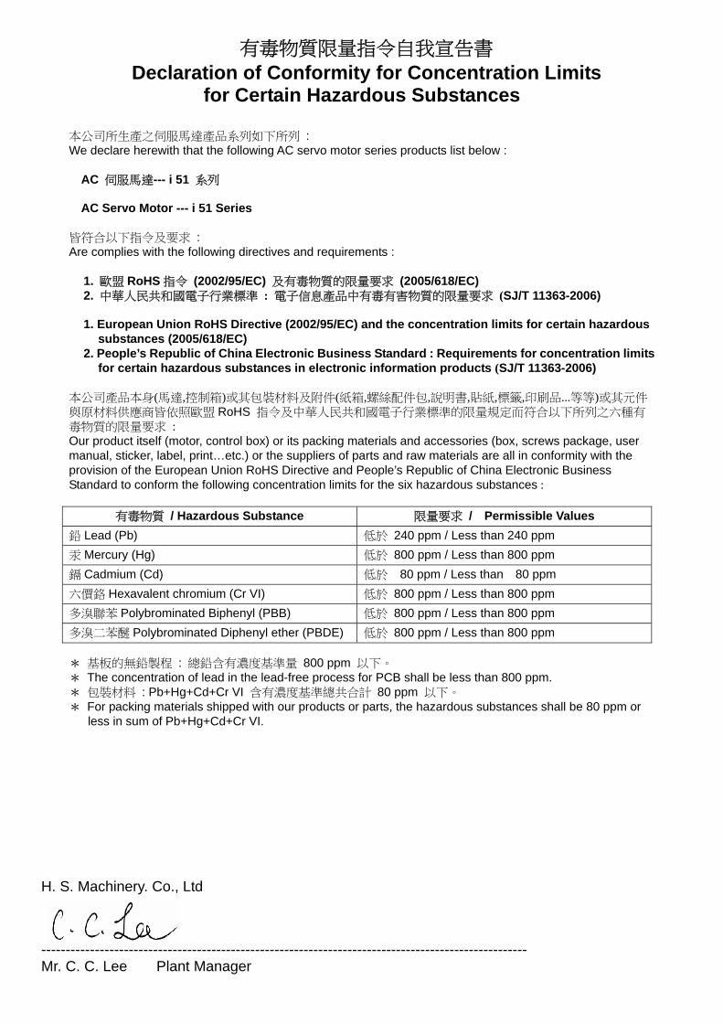
有毒物質限量指令自我宣告書 Declaration of Conformity for Concentration Limits
for Certain Hazardous Substances
本公司所生產之伺服馬達產品系列如下所列 : We declare herewith that the following AC servo motor series products list below :
AC 伺服馬達--- i 51 系列 AC Servo Motor --- i 51 Series
皆符合以下指令及要求 : Are complies with the following directives and requirements :
1. 歐盟 RoHS 指令 (2002/95/EC) 及有毒物質的限量要求 (2005/618/EC) 2. 中華人民共和國電子行業標準 : 電子信息產品中有毒有害物質的限量要求 (SJ/T 11363-2006) 1. European Union RoHS Directive (2002/95/EC) and the concentration limits for certain hazardous
substances (2005/618/EC) 2. People’s Republic of China Electronic Business Standard : Requirements for concentration limits
for certain hazardous substances in electronic information products (SJ/T 11363-2006) 本公司產品本身(馬達,控制箱)或其包裝材料及附件(紙箱,螺絲配件包,說明書,貼紙,標籤,印刷品...等等)或其元件與原材料供應商皆依照歐盟 RoHS 指令及中華人民共和國電子行業標準的限量規定而符合以下所列之六種有毒物質的限量要求 : Our product itself (motor, control box) or its packing materials and accessories (box, screws package, user manual, sticker, label, print…etc.) or the suppliers of parts and raw materials are all in conformity with the provision of the European Union RoHS Directive and People’s Republic of China Electronic Business Standard to conform the following concentration limits for the six hazardous substances :
有毒物質 / Hazardous Substance 限量要求 / Permissible Values
鉛 Lead (Pb) 低於 240 ppm / Less than 240 ppm
汞 Mercury (Hg) 低於 800 ppm / Less than 800 ppm
鎘 Cadmium (Cd) 低於 80 ppm / Less than 80 ppm
六價鉻 Hexavalent chromium (Cr VI) 低於 800 ppm / Less than 800 ppm
多溴聯苯 Polybrominated Biphenyl (PBB) 低於 800 ppm / Less than 800 ppm
多溴二苯醚 Polybrominated Diphenyl ether (PBDE) 低於 800 ppm / Less than 800 ppm * 基板的無鉛製程 : 總鉛含有濃度基準量 800 ppm 以下。 * The concentration of lead in the lead-free process for PCB shall be less than 800 ppm. * 包裝材料 : Pb+Hg+Cd+Cr VI 含有濃度基準總共合計 80 ppm 以下。 * For packing materials shipped with our products or parts, the hazardous substances shall be 80 ppm or
less in sum of Pb+Hg+Cd+Cr VI.
H. S. Machinery. Co., Ltd
---------------------------------------------------------------------------------------------------- Mr. C. C. Lee Plant Manager
1.安全上的注意事項
1.1 作業環境的安全 ………………………………………………………………………………………
1.2 安裝的安全 ……………………………………………………………………………………………
1.3 操作中的安全 …………………………………………………………………………………………
1.4 保養維修的安全 ………………………………………………………………………………………
1.5 保養維修的規定 ………………………………………………………………………………………
1.6 危險標示、注意標示 …………………………………………………………………………………
1.7 保固期限規定 …………………………………………………………………………………………
2.安裝與調整 (1). 馬達的安裝 ……………………………………………………………………………………………
(2). 控制箱的安裝 …………………………………………………………………………………………
(3). 控速器的安裝 …………………………………………………………………………………………
(4). 控速器前、後踏力量調整……………………………………………………………………………
3.接線與接地
(1). 單相與三相電源線的接法 ……………………………………………………………………………
(2). 當電源系統配置為三相四線式 380 V,欲使用單相 220 V 供應伺服電機時的接線方式 ………
(3). 當單相 220 V 伺服電機欲使用在三相 220 V 的電壓時,須注意配置使用上的負載平衡 ……… 4.控制箱各部位名稱 (1). 控制箱正面 ……………………………………………………………………………………………
(2). 控制箱背面 ……………………………………………………………………………………………
5.LED 字幕畫面的顯示模式 (1). 如何進入【一般模式】操作畫面區 …………………………………………………………………
(2). 在【一般模式】畫面區,平車機型時面板按鍵的功能與定義 ……………………………………
(3). 在【一般模式】畫面區,三本車機型時面板按鍵的功能與定義 …………………………………
(4). 在【一般模式】進入『連續回縫』與『定針縫』操作模式畫面 …………………………………
(5). 如何進入第一階【參數模式 A 】畫面區的操作步驟………………………………………………
(6). 如何進入第二階【參數模式 B 】畫面區的操作步驟………………………………………………
(7). 在【參數模式 A 與 B 】畫面區時,面板按鍵的功能與定義……………………………………
(8). 如何進入【參數內容區 】進行調整設定 ……………………………………………………………
(9). 在【參數內容區 】時,A、B、C、D 鍵調整設定的表示值………………………………………
6.常用參數內容表 ………………………………………………………………………………………
7.簡易故障排除
(1). 錯誤信息 ERO. 之顯示碼與排除對策 …………………………………………………………………
(2). 保險絲的更換 …………………………………………………………………………………………
(3). i 51 部品表 ……………………………………………………………………………………………
8.端子座 Pin 功能配置圖 (1).i 51 - 4 –AS ……………………………………………………………………………………………
封底: 七段顯示器字體與實際數值對照表
12
13
14
15
16
型 式 : i 51 系列目 次
頁次
1
1
2
2
2
2
2
3
3
3
4
5
5
5
6
6
7
7
8
8
9
9
10
10
11
- 1 -
1.安全上的注意事項 :
在使用或安裝 i 51 型伺服馬達系列控制箱驅動裝置時,請注意下列事項。
本驅動裝置僅適用於指定範圍的縫製機械,請勿移做其他用途。
1.1 作業環境的安全 :
(1).電源電壓 :
電源電壓請遵照控制箱銘牌所標示之規格 ±10 %範圍內操作。
(2).電磁波干擾 :
請遠離高週磁波機器或電波發射器等,以免所產生的電磁波干擾本驅動裝置因而發生
錯誤動作。
(3).溫濕度 :
a.請不要在室溫 45°C 以上或 5°C 以下的場所操作。
b.請不要在日光直接照射的場所或室外運作。
c.請不要在暖氣 (電熱器) 旁運作。
d.請不要在相對濕度 30 % 以下或 95 % 以上或有露水的場所運作。
(4).空氣 :
a.請不要在多灰塵或具有腐蝕性物質的場所操作。
b.請不要在有揮發性氣体的場所操作。
1.2 安裝的安全 :
(1).馬達、控制箱 : 請遵照說明書正確裝好。
(2).附屬品 : 如要裝配其它選購配件或附屬品時,請先關閉電源並拔掉電源線插頭。
(3).電源線 :
a.請注意不要被外物壓住或過度扭曲電源線。
b.裝釘電源線時請不要靠近會轉動的皮帶輪及三角皮帶,最少要離開 3 公分以上。
c.當連接電源線到電源插座時,應確定此供應電壓必須符合標示在控制箱銘牌上的指定電
壓 ±10 %內。
※注意 : 控制箱電源系統為 AC 220V 時,請勿插接到 AC 380V 的電 源插座上,否則將出現錯誤碼 。此時請立即關閉電源開
關,重新檢查電源。持續供應 380V 超過五分鐘以上,將會燒毀基板而
危及人身安全。 (4).接地 :
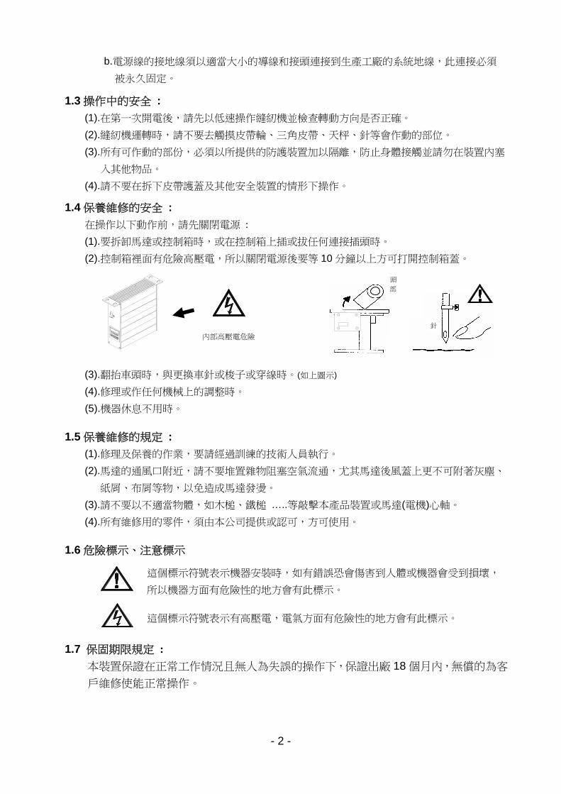
a.為防止雜訊干擾或漏電事故,請做好接地工程。(包括縫紉機、馬達、控制箱、定位器)
使用前請詳細閱讀本技術資料與所搭配的縫製機械說明書,配合正確使用,並須
由接受過正確訓練的人員來安裝或操作。
.
接地線 (綠/黃 色) 請務必做好接地
工程。如果沒有接地,漏電流將對人
體造成不適或傷害。 接控制箱端
棕色線
藍色線
綠 / 黃 色線
( 接地線)
雜訊干擾
請遠離雜訊干擾
- 2 -
b.電源線的接地線須以適當大小的導線和接頭連接到生產工廠的系統地線,此連接必須
被永久固定。
1.3 操作中的安全 :
(1).在第一次開電後,請先以低速操作縫紉機並檢查轉動方向是否正確。
(2).縫紉機運轉時,請不要去觸摸皮帶輪、三角皮帶、天枰、針等會作動的部位。
(3).所有可作動的部份,必須以所提供的防護裝置加以隔離,防止身體接觸並請勿在裝置內塞
入其他物品。
(4).請不要在拆下皮帶護蓋及其他安全裝置的情形下操作。
1.4 保養維修的安全 :
在操作以下動作前,請先關閉電源 :
(1).要拆卸馬達或控制箱時,或在控制箱上插或拔任何連接插頭時。
(2).控制箱裡面有危險高壓電,所以關閉電源後要等 10 分鐘以上方可打開控制箱蓋。
(3).翻抬車頭時,與更換車針或梭子或穿線時。(如上圖示)
(4).修理或作任何機械上的調整時。
(5).機器休息不用時。
1.5 保養維修的規定 :
(1).修理及保養的作業,要請經過訓練的技術人員執行。
(2).馬達的通風口附近,請不要堆置雜物阻塞空氣流通,尤其馬達後風蓋上更不可附著灰塵、
紙屑、布屑等物,以免造成馬達發燙。
(3).請不要以不適當物體,如木槌、鐵槌 …..等敲擊本產品裝置或馬達(電機)心軸。
(4).所有維修用的零件,須由本公司提供或認可,方可使用。
1.6 危險標示、注意標示
這個標示符號表示機器安裝時,如有錯誤恐會傷害到人體或機器會受到損壞,
所以機器方面有危險性的地方會有此標示。
這個標示符號表示有高壓電,電氣方面有危險性的地方會有此標示。
1.7 保固期限規定 :
本裝置保證在正常工作情況且無人為失誤的操作下,保證出廠 18 個月內,無償的為客
戶維修使能正常操作。
內部高壓電危險
頭
部
針
- 3 -
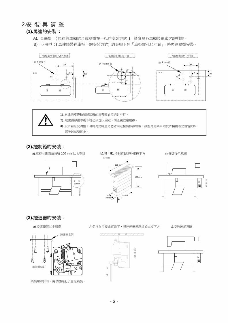
2.安 裝 與 調 整
(1).馬達的安裝 :
A). 直驅型 : ( 馬達與車頭結合或懸掛在一起的安裝方式 ) 請參閱各車頭製造廠之說明書。
B). 泛用型 : ( 馬達鎖裝在車板下的安裝方式) 請參照下列『車板鑽孔尺寸圖』,將馬達懸掛安裝。
(2).控制箱的安裝 :
(3).控速器的安裝 :
a).車板右側面須預留 100 mm 以上空間 b).將 i 51 控制箱鎖裝於車板下方 c).安裝後示意圖
100 mm
預留空間
一般標準尺寸圖 (USA 標準)
57
216
油 槽
66
105
鉆 9 mm 孔
車 板
電纜線穿過孔尺寸圖
鉆 40 mm 孔
70
槽
70
油
57
190
油 槽
70
105
德國標準 DIN 尺寸圖
車 板
鉆 9 mm 孔
1). 馬達的皮帶輪和縫紉機的皮帶輪必須絕對平行。
2). 電纜線穿過車板下後必須加以固定,防止被皮帶磨擦。
3). 皮帶鬆緊度調整,可將馬達腳座之懸臂固定栓稍作微鬆後,調整馬達與車頭皮帶輪兩者之適當間距,
再予以鎖緊固定。
a).控速器與其支架座 b).保持在吊桿成直線下,將控速器連座鎖於車板下方 c).安裝後示意圖
控
速
器
車 板
吊
桿
鎖裝螺絲釘
控速器支架
鎖裝螺絲釘時,需以螺絲起子全程鎖裝。
70mm
229 mm
157 mm
尺寸圖
180 mm
控
制
箱
- 4 -
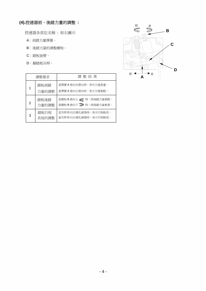
(4).控速器前、後踏力量的調整 :
控速器各部位名稱 : 如右圖示
A : 前踏力量彈簧。
B : 後踏力量的調整螺栓。
C : 踏板旋臂。
D : 腳踏板吊桿。
B
A
C
D輕 重
重 輕
1
2
3
調整需求
踏板前踏
力量的調整
踏板後踏
力量的調整
踏板行程
長短的調整
調 整 結 果
當彈簧 A 愈向右側勾時,表示力量愈重。
當彈簧 A 愈向左側勾時,表示力量愈輕。
當螺栓 B 愈向上 時,則後踏力量愈輕。
當螺栓 B 愈向下 時,則後踏力量愈重。
當吊桿 D 向右側孔鎖裝時,表示行程較長。
當吊桿 D 向左側孔鎖裝時,表示行程較短。
- 5 -
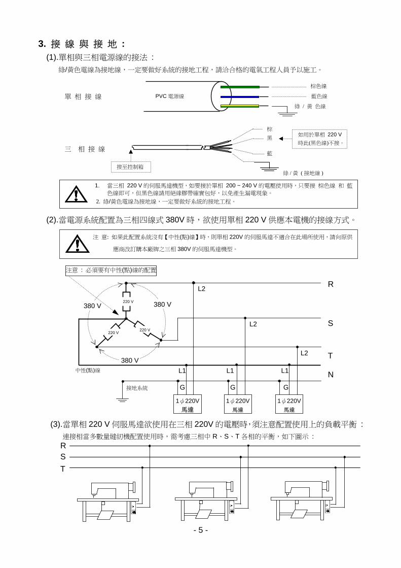
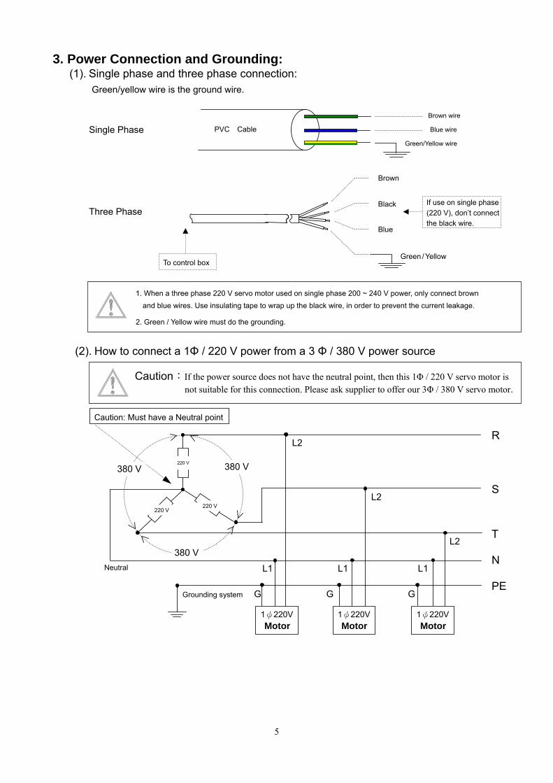
3. 接 線 與 接 地 : (1).單相與三相電源線的接法 :
綠/黃色電線為接地線,一定要做好系統的接地工程,請洽合格的電氣工程人員予以施工。
(2).當電源系統配置為三相四線式 380V 時,欲使用單相 220 V 供應本電機的接線方式。
(3).當單相 220 V 伺服馬達欲使用在三相 220V 的電壓時,須注意配置使用上的負載平衡 :
連接相當多數量縫紉機配置使用時,需考慮三相中 R、S、T 各相的平衡,如下圖示 :
單 相 接 線 PVC 電源線
棕色線
藍色線
綠 / 黃 色線
1. 當三相 220 V 的伺服馬達機型,如要接於單相 200 ~ 240 V 的電壓使用時,只要接 棕色線 和 藍色線即可,但黑色線請用絕緣膠帶確實包好,以免產生漏電現象。
2. 綠/黃色電線為接地線,一定要做好系統的接地工程。
注 意: 如果此配置系統沒有【中性(點)線】時,則單相 220V 的伺服馬達不適合在此場所使用,請向原供
應商改訂購本廠牌之三相 380V 的伺服馬達機型。
R S
T
三 相 接 線
棕
黑
藍
綠 / 黃 ( 接地線 )
如用於單相 220 V
時此(黑色線)不接。
接至控制箱
R
S
T
N
接地系統 G G G
1ψ220V
馬達 1ψ220V
馬達
1ψ220V
馬達
L1 L1 L1
L2
L2
L2
中性(點)線
注意 : 必須要有中性(點)線的配置
380 V 380 V 220 V
220 V 220 V
380 V
- 6 -
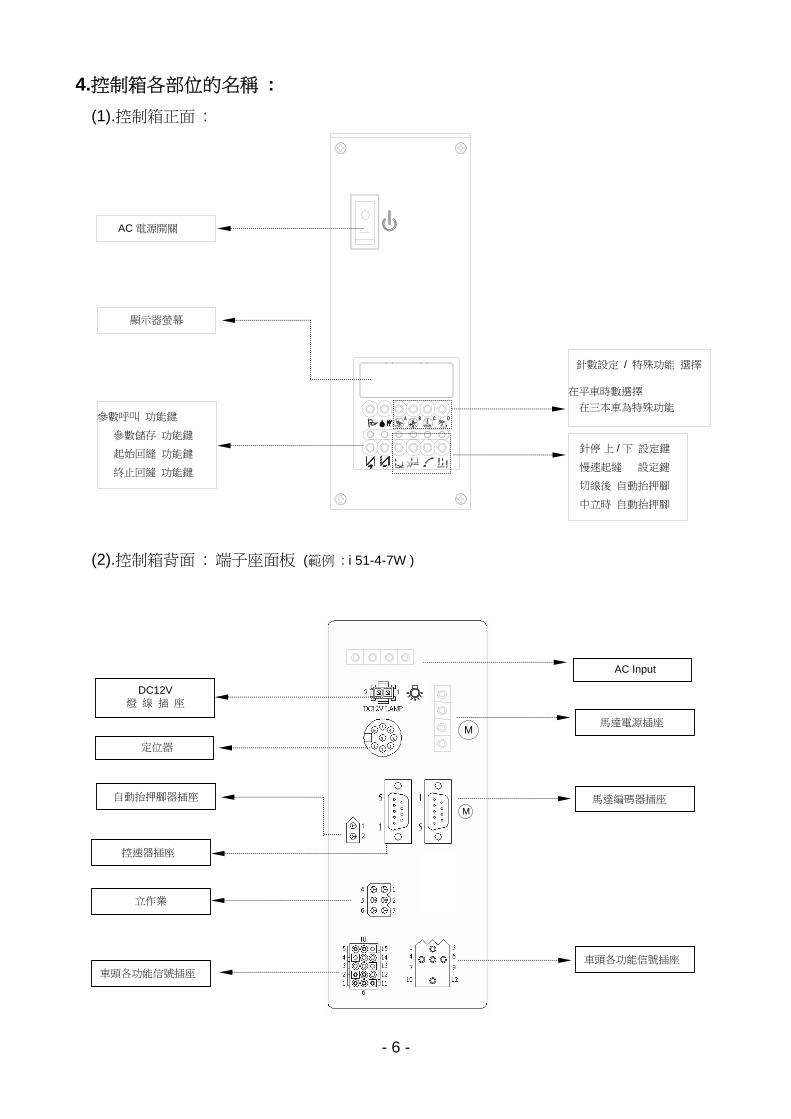
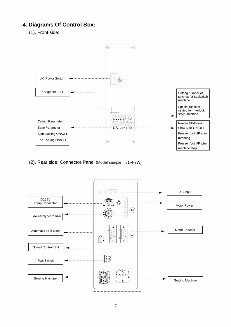
4.控制箱各部位的名稱 :
(1).控制箱正面 :
(2).控制箱背面 : 端子座面板 (範例 : i 51-4-7W )
馬達電源插座
馬達編碼器插座
控速器插座
立作業
車頭各功能信號插座
DC12V 燈 線 插 座
自動抬押腳器插座
AC Input
定位器
STOP
顯示器螢幕
針數設定 / 特殊功能 選擇
在平車時數選擇
在三本車為特殊功能
AC 電源開關
參數呼叫 功能鍵
參數儲存 功能鍵
起始回縫 功能鍵
終止回縫 功能鍵
針停 上 / 下 設定鍵
慢速起縫 設定鍵
切線後 自動抬押腳
中立時 自動抬押腳
M
M
車頭各功能信號插座
- 7 -
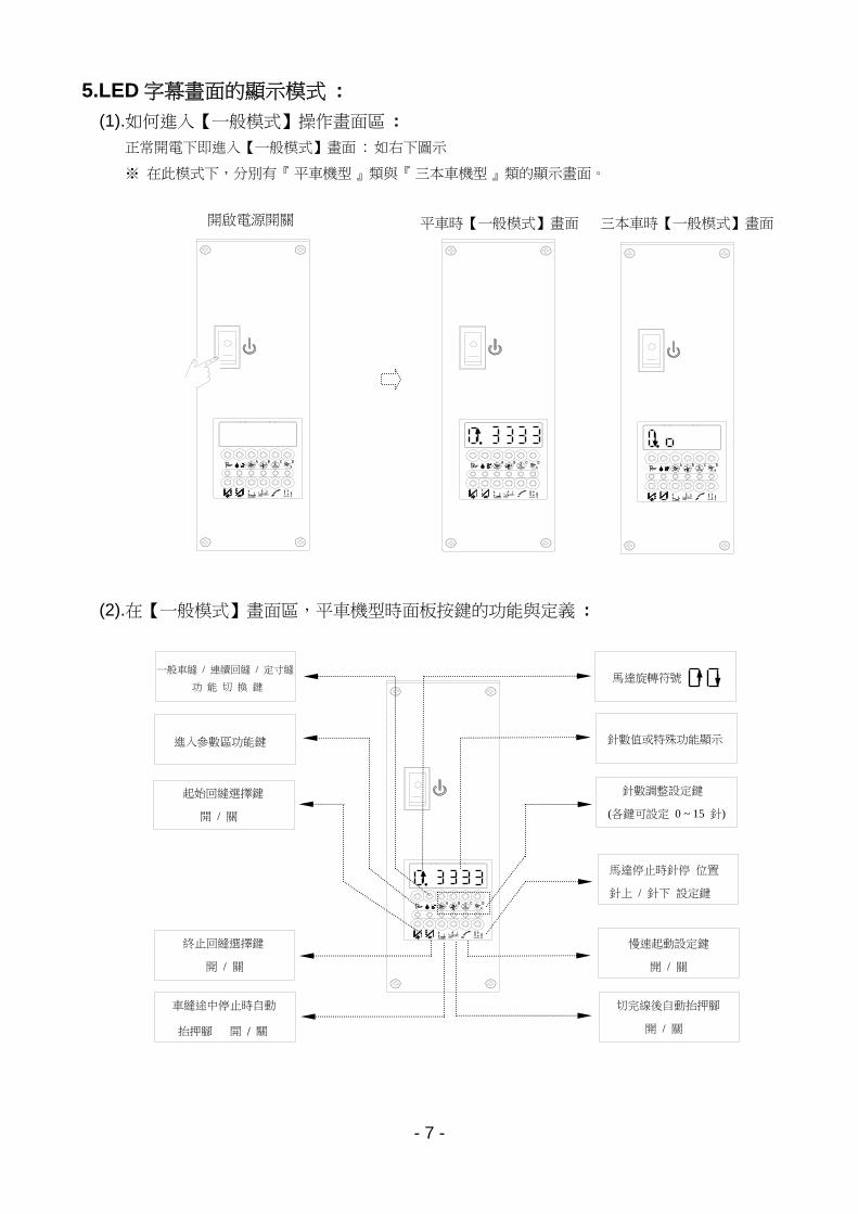
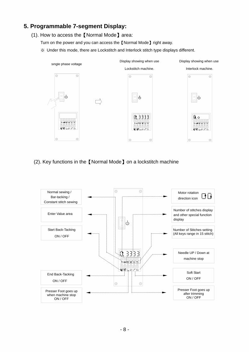
5.LED 字幕畫面的顯示模式 :
(1).如何進入【一般模式】操作畫面區 :
正常開電下即進入【一般模式】畫面 : 如右下圖示
※ 在此模式下,分別有『 平車機型 』類與『 三本車機型 』類的顯示畫面。
(2).在【一般模式】畫面區,平車機型時面板按鍵的功能與定義 :
STOP
.
平車時【一般模式】畫面 三本車時【一般模式】畫面 開啟電源開關
針數調整設定鍵
(各鍵可設定 0 ~ 15 針)
馬達旋轉符號
慢速起動設定鍵
開 / 關
馬達停止時針停 位置
針上 / 針下 設定鍵
針數值或特殊功能顯示
切完線後自動抬押腳
開 / 關
一般車縫 / 連續回縫 / 定寸縫
功 能 切 換 鍵
進入參數區功能鍵
車縫途中停止時自動
抬押腳 開 / 關
起始回縫選擇鍵
開 / 關
終止回縫選擇鍵
開 / 關
STOP STOP
STOP
. .
- 8 -
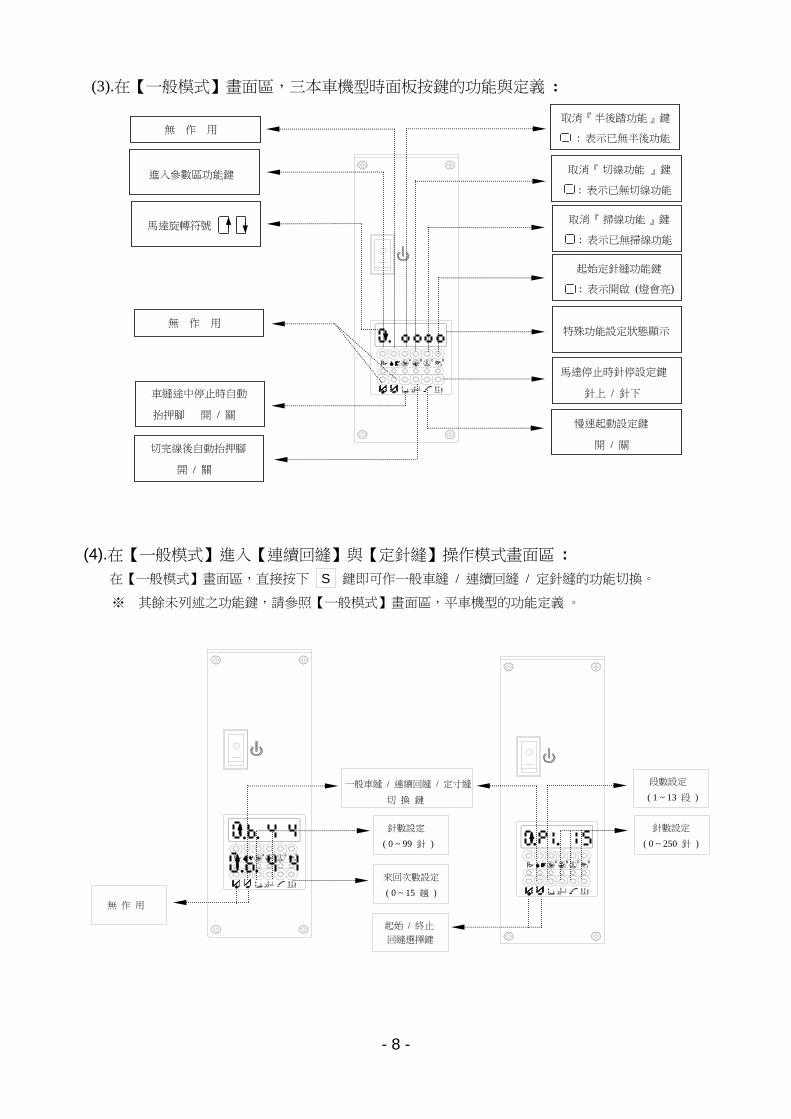
(3).在【一般模式】畫面區,三本車機型時面板按鍵的功能與定義 :
(4).在【一般模式】進入【連續回縫】與【定針縫】操作模式畫面區 :
在【一般模式】畫面區,直接按下 鍵即可作一般車縫 / 連續回縫 / 定針縫的功能切換。
STOP
STOP
STOP
一般車縫 / 連續回縫 / 定寸縫
切 換 鍵
.
S
※ 其餘未列述之功能鍵,請參照【一般模式】畫面區,平車機型的功能定義 。
取消『 半後踏功能 』鍵
: 表示已無半後功能
取消『 切線功能 』鍵
: 表示已無切線功能
取消『 掃線功能 』鍵
: 表示已無掃線功能
起始定針縫功能鍵
: 表示開啟 (燈會亮)
馬達停止時針停設定鍵
針上 / 針下
特殊功能設定狀態顯示
慢速起動設定鍵
開 / 關
無 作 用
進入參數區功能鍵
馬達旋轉符號
車縫途中停止時自動
抬押腳 開 / 關
切完線後自動抬押腳
開 / 關
無 作 用
. .
無 作 用
針數設定
( 0 ~ 99 針 )
來回次數設定
( 0 ~ 15 趟 )
段數設定
( 1 ~ 13 段 )
針數設定
( 0 ~ 250 針 ) . .
起始 / 終止
回縫選擇鍵
. .
- 9 -
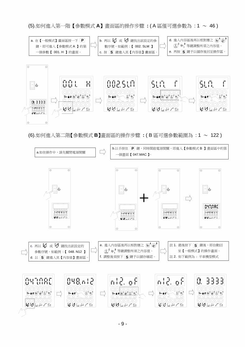
(5).如何進入第一階【參數模式 A】畫面區的操作步驟 : ( A 區僅可選參數為 : 1 ~ 46 )
(6).如何進入第二階【參數模式 B】畫面區的操作步驟 : ( B 區可選參數範圍為 : 1 ~ 122 )
STOP
STOP
STOP
STOPSTOPSTOPSTOPSTOP
STOPSTOPSTOPSTOP
a. 在【一般模式】畫面區按一下 鍵,即可進入【參數模式 A 】的第
一個參數【 001. H 】的畫面。
P b. 再以 或 鍵找出欲設定的參
數序號,如範例 :【 002. SLM 】
c. 按 鍵進入其【內容值】畫面區。S
d. 進入內容區後再以相對應之
等鍵調整所須之內容值。
e. 再按 鍵予以儲存後回至操作區。S
a.如在操作中,請先關閉電源開關 b.以手按住 鍵,同時開啟電源開關,即進入【參數模式 B 】畫面區中的第
一個畫面【 047.MAC 】。
P
c. 再以 或 鍵找出欲設定的 參數序號,如範例 :【 048. N12 】
d. 以 鍵進入其【內容值】畫面區。 S
e. 進入內容區後再以相對應之
等鍵調整所須之內容值。
f. 調整後須按下 鍵予以儲存確認。 S
註 1. 最後按下 鍵後,即自動回
至【一般模式】的操作畫面。
註 2. 如下範例為 : 平車機型模式
S
. . .
. .
STOP
.
.
. . .
. STO P
- 10 -
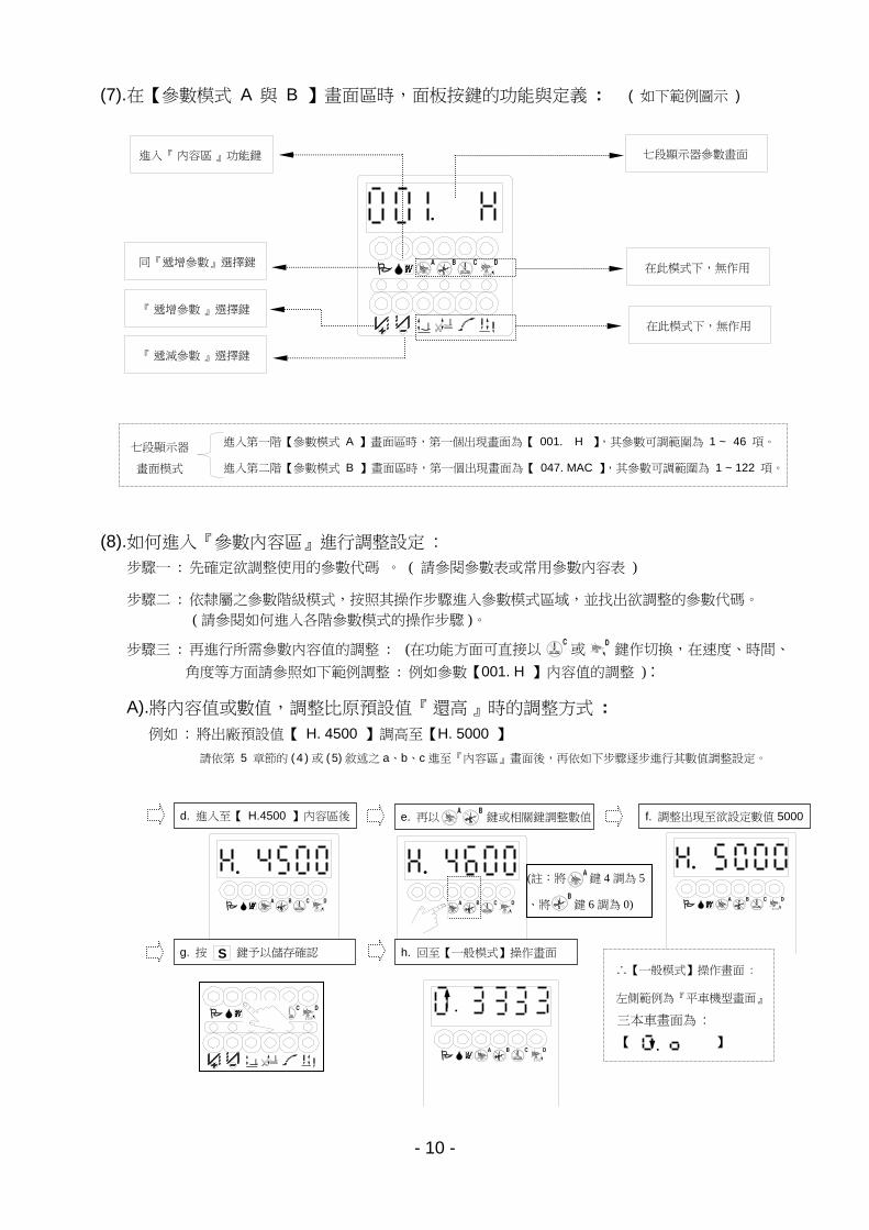
(7).在【參數模式 A 與 B 】畫面區時,面板按鍵的功能與定義 : ( 如下範例圖示 )
(8).如何進入『參數內容區』進行調整設定 :
步驟一 : 先確定欲調整使用的參數代碼 。 ( 請參閱參數表或常用參數內容表 )
步驟二 : 依隸屬之參數階級模式,按照其操作步驟進入參數模式區域,並找出欲調整的參數代碼。
( 請參閱如何進入各階參數模式的操作步驟 )。
步驟三 : 再進行所需參數內容值的調整 : (在功能方面可直接以 或 鍵作切換,在速度、時間、
角度等方面請參照如下範例調整 : 例如參數【001. H 】內容值的調整 ) :
A).將內容值或數值,調整比原預設值『 還高 』時的調整方式 :
例如 : 將出廠預設值【 H. 4500 】調高至【H. 5000 】
請依第 5 章節的 ( 4 ) 或 ( 5) 敘述之 a、b、c 進至『內容區』畫面後,再依如下步驟逐步進行其數值調整設定。
STOP
STOP
STOP
STOP STOP
STOP
進入第一階【參數模式 A 】畫面區時,第一個出現畫面為【 001. H 】,其參數可調範圍為 1 ~ 46 項。
進入第二階【參數模式 B 】畫面區時,第一個出現畫面為【 047. MAC 】,其參數可調範圍為 1 ~ 122 項。
七段顯示器
畫面模式
d. 進入至【 H.4500 】內容區後 e. 再以 鍵或相關鍵調整數值 f. 調整出現至欲設定數值 5000
g. 按 鍵予以儲存確認 S
.
h. 回至【一般模式】操作畫面 ∴【一般模式】操作畫面 :
左側範例為『平車機型畫面』
三本車畫面為 :
【 】 .
『 遞減參數 』選擇鍵
『 遞增參數 』選擇鍵
在此模式下,無作用
同『遞增參數』選擇鍵
進入『 內容區 』功能鍵 七段顯示器參數畫面
在此模式下,無作用
. .
.
.
(註:將 鍵 4 調為 5
、將 鍵 6 調為 0)
- 11 -
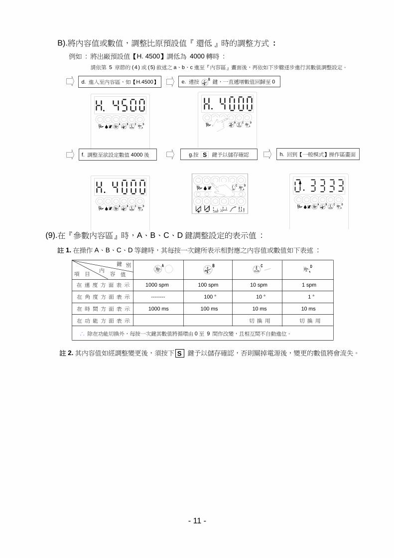
B).將內容值或數值,調整比原預設值『 還低 』時的調整方式 :
例如 : 將出廠預設值【H. 4500】調低為 4000 轉時 :
請依第 5 章節的 ( 4 ) 或 ( 5) 敘述之 a、b、c 進至『內容區』畫面後,再依如下步驟逐步進行其數值調整設定。
(9).在『參數內容區』時,A、B、C、D 鍵調整設定的表示值 :
STOP
STOP
註 1. 在操作 A、B、C、D 等鍵時,其每按一次鍵所表示相對應之內容值或數值如下表述 :
註 2. 其內容值如經調整變更後,須按下 鍵予以儲存確認,否則關掉電源後,變更的數值將會流失。 S
內 容 值 項 目
別 鍵
在 速 度 方 面 表 示 1000 spm 100 spm 10 spm 1 spm
在 角 度 方 面 表 示 -------- 100 ° 10 ° 1 °
在 時 間 方 面 表 示 1000 ms 100 ms 10 ms 10 ms
在 功 能 方 面 表 示 切 換 用 切 換 用
∴ 除在功能切換外,每按一次鍵其數值將循環由 0 至 9 間作改變,且相互間不自動進位。
d. 進入至內容區,如【H.4500】 e. 連按 鍵,一直遞增數值回歸至 0
f. 調整至欲設定數值 4000 後 g.按 鍵予以儲存確認 S h. 回到【一般模式】操作區畫面
.
.
STOP
.
STOP
. STOP
- 12 -
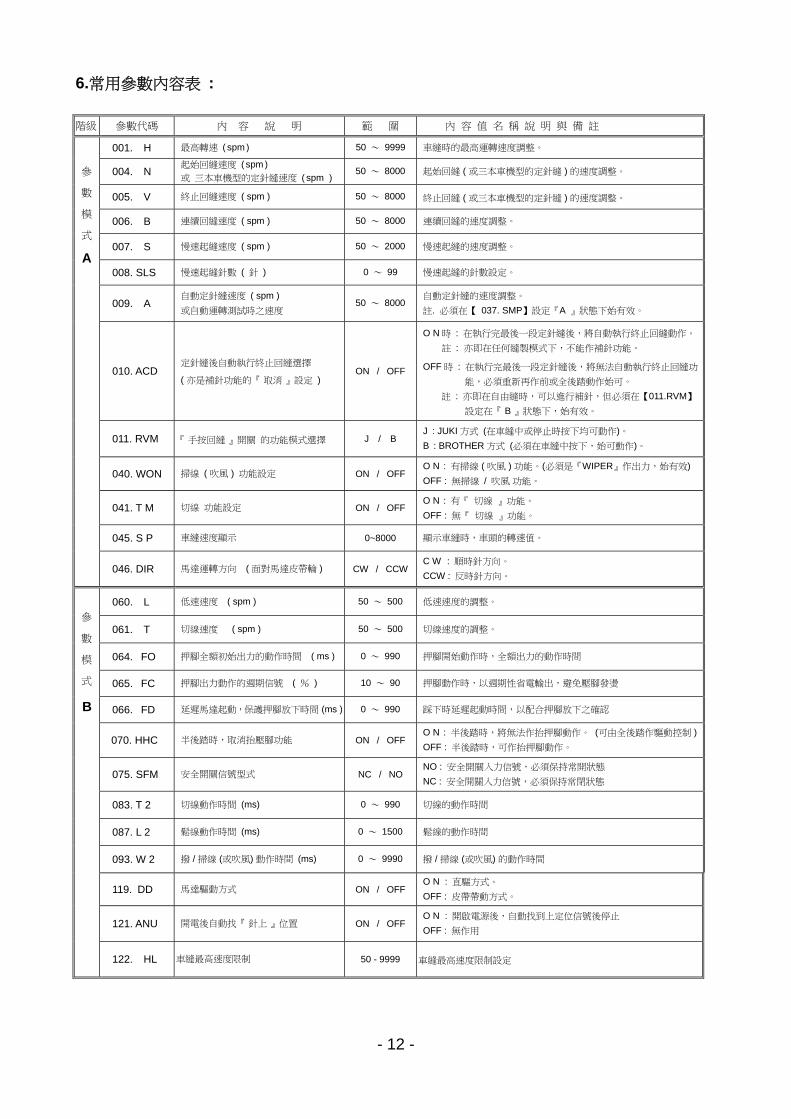
6.常用參數內容表 :
階級 參數代碼 內 容 說 明 範 圍 內 容 值 名 稱 說 明 與 備 註
001. H 最高轉速 ( spm ) 50 ~ 9999 車縫時的最高運轉速度調整。
004. N 起始回縫速度 ( spm )
或 三本車機型的定針縫速度 ( spm ) 50 ~ 8000 起始回縫 ( 或三本車機型的定針縫 ) 的速度調整。
005. V 終止回縫速度 ( spm ) 50 ~ 8000 終止回縫 ( 或三本車機型的定針縫 ) 的速度調整。
006. B 連續回縫速度 ( spm ) 50 ~ 8000 連續回縫的速度調整。
007. S 慢速起縫速度 ( spm ) 50 ~ 2000 慢速起縫的速度調整。
008. SLS 慢速起縫針數 ( 針 ) 0 ~ 99 慢速起縫的針數設定。
009. A 自動定針縫速度 ( spm )
或自動運轉測試時之速度 50 ~ 8000
自動定針縫的速度調整。
註. 必須在【 037. SMP】設定『A 』狀態下始有效。
010. ACD 定針縫後自動執行終止回縫選擇
( 亦是補針功能的『 取消 』設定 ) ON / OFF
O N 時 : 在執行完最後一段定針縫後,將自動執行終止回縫動作。
註 : 亦即在任何縫製模式下,不能作補針功能。
OFF 時 : 在執行完最後一段定針縫後,將無法自動執行終止回縫功
能,必須重新再作前或全後踏動作始可。
註 : 亦即在自由縫時,可以進行補針,但必須在【011.RVM】
設定在『 B 』狀態下,始有效。
011. RVM 『 手按回縫 』開關 的功能模式選擇 J / B J : JUKI 方式 (在車縫中或停止時按下均可動作)。
B : BROTHER 方式 (必須在車縫中按下,始可動作)。
040. WON 掃線 ( 吹風 ) 功能設定 ON / OFF O N : 有掃線 ( 吹風 ) 功能。(必須是『WIPER』作出力,始有效)
OFF : 無掃線 / 吹風 功能。
041. T M 切線 功能設定 ON / OFF O N : 有『 切線 』功能。
OFF : 無『 切線 』功能。
045. S P 車縫速度顯示 0~8000 顯示車縫時,車頭的轉速值。
參
數
模
式
046. DIR 馬達運轉方向 ( 面對馬達皮帶輪 ) CW / CCW
C W : 順時針方向。
CCW : 反時針方向。
060. L 低速速度 ( spm ) 50 ~ 500 低速速度的調整。
061. T 切線速度 ( spm ) 50 ~ 500 切線速度的調整。
064. FO 押腳全額初始出力的動作時間 ( ms ) 0 ~ 990 押腳開始動作時,全額出力的動作時間
065. FC 押腳出力動作的週期信號 ( % ) 10 ~ 90 押腳動作時,以週期性省電輸出,避免壓腳發燙
066. FD 延遲馬達起動,保護押腳放下時間 (ms ) 0 ~ 990 踩下時延遲起動時間,以配合押腳放下之確認
070. HHC 半後踏時,取消抬壓腳功能 ON / OFF O N : 半後踏時,將無法作抬押腳動作。 (可由全後踏作驅動控制 )
OFF : 半後踏時,可作抬押腳動作。
075. SFM 安全開關信號型式 NC / NO NO : 安全開關入力信號,必須保持常開狀態
NC : 安全開關入力信號,必須保持常閉狀態
083. T 2 切線動作時間 (ms) 0 ~ 990 切線的動作時間
087. L 2 鬆線動作時間 (ms) 0 ~ 1500 鬆線的動作時間
093. W 2 撥 / 掃線 (或吹風) 動作時間 (ms) 0 ~ 9990 撥 / 掃線 (或吹風) 的動作時間
119. DD 馬達驅動方式 ON / OFF O N : 直驅方式。
OFF : 皮帶帶動方式。
參
數
模
式
121. ANU 開電後自動找『 針上 』位置 ON / OFF O N : 開啟電源後,自動找到上定位信號後停止
OFF : 無作用
122. HL 車縫最高速度限制 50 - 9999 車縫最高速度限制設定
A
B
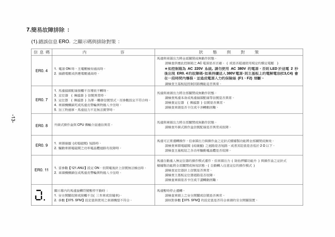
7.簡易故障排除 :
(1).錯誤信息 ERO. 之顯示碼與排除對策 :
信 息 碼 內 容 狀 態 與 對 策
ER0. 4 1. 電源 ON 時,主電壓檢知過高時。 2. 插錯電壓或供應電壓過高時。
馬達與車頭出力將全部關閉成無動作狀態。 請檢查供應此控制箱之 AC 電源是否正確。 ( 或是否超過使用規定的額定電壓 )
*如控制箱為 AC 220V 系統, 請勿使用 AC 380V 的電源,否則 LED 於送電 2 秒後出現 ER0. 4的故障碼。如果持續送入380V電源,則主基板上的電解電容(C3,C4) 會在一段時間內爆裂,並造成電源入力的保險絲 (F1、F2) 熔斷。
請檢查主基板組控制回路機能是否異常。
ER0. 7
1. 馬達插頭配線接觸不良導致不轉時。 3. 定位器 ( 傳感器 ) 信號異常時。
3. 定位器 ( 傳感器 ) 為單一觸發信號型式,而參數設定不符合時。
4. 車頭機構鎖死或馬達皮帶輪異物捲入卡住時。 5. 加工物過厚,馬達扭力不足無法貫穿時。
馬達與車頭出力將全部關閉成無動作狀態。 請檢查馬達本身或馬達插頭配線等信號是否異常。 請檢查定位器 ( 傳感器 ) 信號是否異常。 請檢查車頭是否卡住或干涉轉動困難。
ER0. 8
外掛式操作盒與 CPU 傳輸介面通信異常。 馬達與車頭出力將全部關閉成無動作狀態。 請檢查外掛式操作盒信號配線是否異常或故障。
ER0. 9 1. 車頭線圈 (或電磁閥) 短路時。 2. 驅動車頭電磁閥之功率電晶體迴路有故障時。
馬達可正常運轉操作,但車頭出力與操作盒之定針式樣縫製功能將全部關閉成無效。 請檢查車頭電磁閥 (或線圈) 之迴路是否短路,或者其阻值是否低於 2 Ω以下。 請檢查主基板組之各功率驅動電晶體是否故障。
ER0. 11 1. 當參數【121.ANU】設定 ON,但開電後針上信號無法檢出時。 2. 車頭機構鎖住或馬達皮帶輪異物捲入卡住時。
馬達自動進入無定位器的操作模式運作,但車頭出力 ( 除抬押腳功能外 ) 與操作盒之定針式 樣縫製功能將全部關閉成無效狀態。( 自動轉入任意定位的操作模式 ) 請檢查定位器針上信號是否異常。 請檢查主基板定位器迴路是否故障。 請檢查車頭是否卡住或干澀轉動困難。
顯示幕內的馬達旋轉符號暫停不動時 : 1. 安全開關故障或接觸不良( 三本車或盲縫車)。
2. 參數【075. SFM】設定值與使用之車頭機型不符合。
馬達暫時停止運轉。 請檢查車頭上之安全開關或信號是否異常。 請核對參數【075. SFM】的設定值是否符合車頭的安全開關裝置。
.
-13-
- 14 -
(2).保險絲的更換 :
保險絲位置與規格 : 如保險絲燒斷時,請先把原因排除後再更換相同容量的保險絲。
注 意 : 在打開控制箱蓋之前,請先將電源關閉約 10 分鐘後,才可打開控制箱蓋。
F1、F2 保險絲為 15 A / 250V
( AC 電源入力保護用 )
基板組正視圖 :
15 A
15 A
F1
F2
RELAY
S
C 4 C 9
JP 224 V
NTC
JP 130 V
- 15 -
編號 元件料號 品 名 規格與備註 編號 元件料號 品 名 規格與備註
1 2VP34XX209XXX 馬達本體組 依客戶選用 2- 2 2VP70304201 水泥電阻組 For i 51
2- 3 2VP7M402001 主基板組 1∮ 20 A
1-1 2VPBTV020 馬達腳座組 下掛式馬達專用 2- 4 2VPI5408BR001 端子座面板組 i 51 -4-BR
1- 2 315BGV080 皮帶蓋上蓋 下掛式馬達專用 2VPI54087W001 端子座面板組 i 51 -4-7W
1- 3 2VP2PY40XXX 皮帶輪 依客戶選用
1- 4 315BGV070 皮帶蓋底座 下掛式馬達專用 2- 6 312SMV320 控制箱面板 For i 51
1- 5 313BGE030 皮帶蓋支架 下掛式馬達專用
1- 6 2VP34XX209XXX 馬達單體 依客戶選用 2-8 2VP12MPB29102 控制箱上蓋 For i 51
2 2VPI5400BR201 控制箱 200 〜 240 V 3 2VP70306001 控速器組 For i 51
2VPI54007W201 控制箱 200 〜 240 V 4 2VP11600XXXX 定位器 依客戶選用
2VPI540066201 控制箱 200 〜 240 V
2- 1 2VP12MPB29101 控制箱底座 For i 51
(3) i 51 部品表:
3
1-1 1-2 1-3 1-61-4 1-5
馬達部份
配件部份
控制箱部份1 2
2-2
2-1
2-3
2-4
2-6
2-8
4
- 16 -
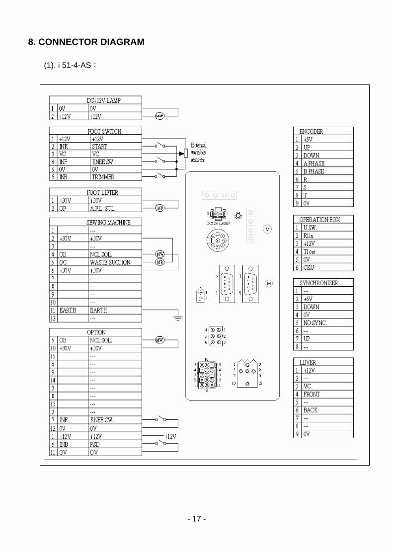
8. 端子座 Pin 功能配置圖 :
(1). i 51-4-AS:
M
M
1. Safety Precaution
1.1 Work environment ……………………………………………………………………………………… 1.2 Safety in installation …………………………………………………………………………………… 1.3 Safety in operating …………………………………………………………………………………… 1.4 Safety in maintenance and repairs …………………………………………………………………… 1.5 Regulation in maintenance and repairs ………………………………………………………………… 1.6 Danger and caution signs ……………………………………………………………………………… 1.7 Warranty information ………………………………………………………………………………
2. Installation and Adjustment (1). Motor installation …………………………………………………………………………………… (2). Control box installation ………………………………………………………………………………… (3). Speed control unit installation ……………………………………………………………………… (4). Adjust the speed control unit …………………………………………………………………………
3. Power Connection and Grounding
(1). Single phase and three phase connection ………………………………………………………… (2). How to connect a 1Φ / 220 V power from a 3 Φ / 380 V power source ………………………
(3). The load balance when use a 1Φ / 220 V motor used on a 3 Φ / 220 V power source ………
4. Diagrams of Control Box (1). Front side of the control box ……………………………………………………………………… (2). Rear side of the control box ………………………………………………………………………
5. Programmable 7-segment Display (1). How to access the【Normal Mode】 …………………………………………………………… (2). Key functions in the【Normal Mode】for a lockstitch machine ……………………………… (3). Key functions in the【Normal Mode】for a interlock machine ………………………………… (4). How to perform『BAR Tacking』and『Constant-Stitch Sewing』in the【Normal Mode】… (5). How to access 【Parameter Mode A 】………………………………………………………… (6). How to access 【Parameter Mode B 】………………………………………………………… (7). Key functions in the【Parameter Mode A and B】……………………………………………… (8). How to adjust the parameter setting ……………………………………………………………… (9). Setting values for A、B、C、D keys ………………………………………………………………
6. General Parameter Table ………………………………………………………………………
7. Basic Troubleshooting (1). Error code and measurement ……………………………………………………………………… (2). Instruction of fuse replacement ………………………………………………………………………… (3). i51 parts list …………………………………………………………………………………………
9. Basic Diagrams of Connector Panel (1). i51-4-AS ……………………………………………………………………………………………
Appendix : 7-Segment Display Characters Compare Chart
Model : i 51 Series Contents
Page
1 1 2 2 2 2 2
3 3 3 4 5 5
6 7 7
8 8 9 9 10 10 11 11 12
13
14 15 16
17
- 1 -
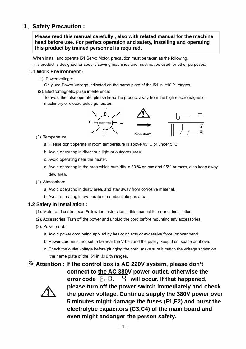
1. Safety Precaution :
When install and operate i51 Servo Motor, precaution must be taken as the following. This product is designed for specify sewing machines and must not be used for other purposes.
1.1 Work Environment :
(1). Power voltage: Only use Power Voltage indicated on the name plate of the i51 in ±10 % ranges. (2). Electromagnetic pulse interference: To avoid the false operate, please keep the product away from the high electromagnetic machinery or electro pulse generator.
(3). Temperature:
a. Please don’t operate in room temperature is above 45°C or under 5°C
b. Avoid operating in direct sun light or outdoors area.
c. Avoid operating near the heater.
d. Avoid operating in the area which humidity is 30 % or less and 95% or more, also keep away
dew area.
(4). Atmosphere:
a. Avoid operating in dusty area, and stay away from corrosive material.
b. Avoid operating in evaporate or combustible gas area.
1.2 Safety In Installation :
(1). Motor and control box: Follow the instruction in this manual for correct installation.
(2). Accessories: Turn off the power and unplug the cord before mounting any accessories.
(3). Power cord:
a. Avoid power cord being applied by heavy objects or excessive force, or over bend.
b. Power cord must not set to be near the V-belt and the pulley, keep 3 cm space or above.
c. Check the outlet voltage before plugging the cord, make sure it match the voltage shown on
the name plate of the i51 in ±10 % ranges.
Attention : If the control box is AC 220V system, please don’t connect to the AC 380V power outlet, otherwise the error code will occur. If that happened, please turn off the power switch immediately and check the power voltage. Continue supply the 380V power over 5 minutes might damage the fuses (F1,F2) and burst the electrolytic capacitors (C3,C4) of the main board and even might endanger the person safety.
Please read this manual carefully , also with related manual for the machine head before use. For perfect operation and safety, installing and operating this product by trained personnel is required.
Interference
Keep away
※
.
- 2 -
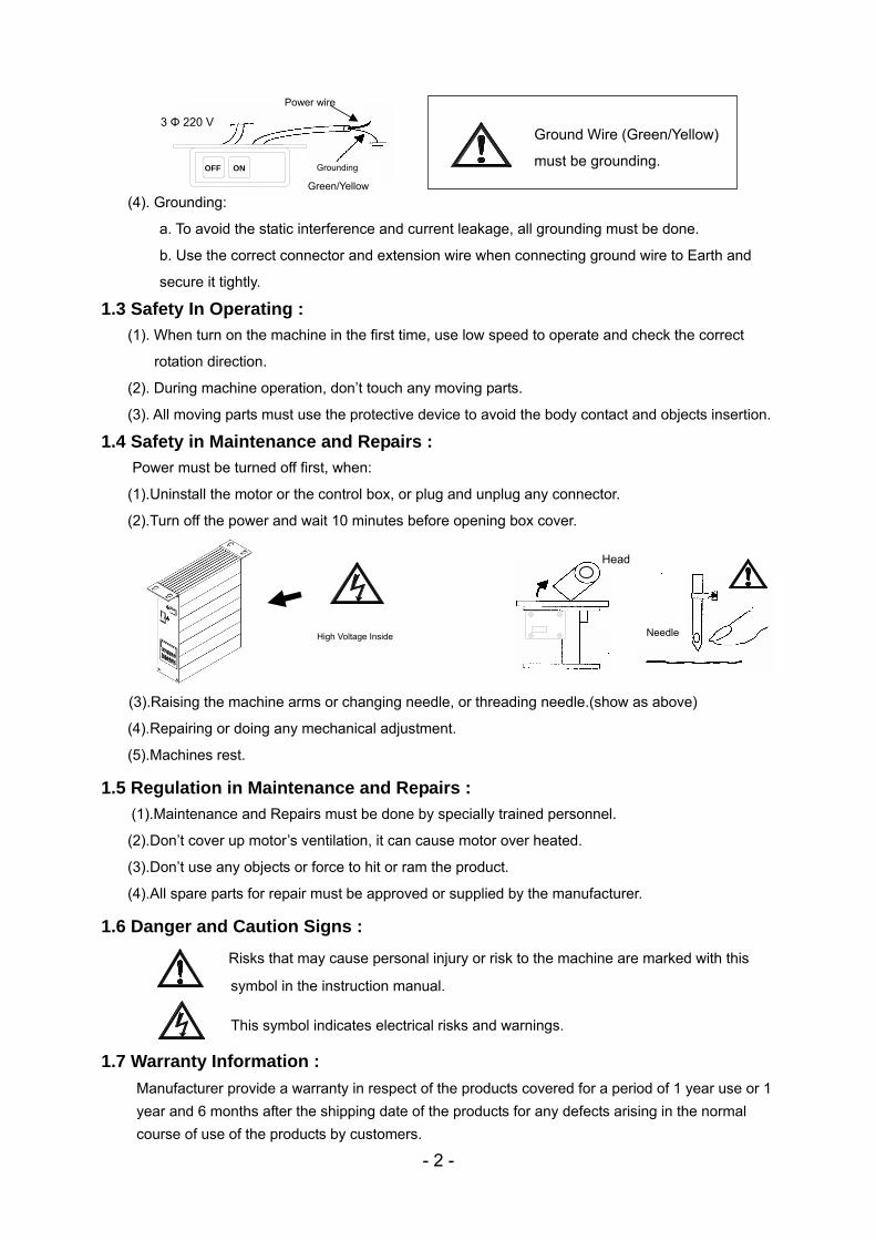
(4). Grounding:
a. To avoid the static interference and current leakage, all grounding must be done.
b. Use the correct connector and extension wire when connecting ground wire to Earth and
secure it tightly.
1.3 Safety In Operating :
(1). When turn on the machine in the first time, use low speed to operate and check the correct
rotation direction.
(2). During machine operation, don’t touch any moving parts.
(3). All moving parts must use the protective device to avoid the body contact and objects insertion.
1.4 Safety in Maintenance and Repairs :
Power must be turned off first, when:
(1).Uninstall the motor or the control box, or plug and unplug any connector.
(2).Turn off the power and wait 10 minutes before opening box cover.
(3).Raising the machine arms or changing needle, or threading needle.(show as above)
(4).Repairing or doing any mechanical adjustment.
(5).Machines rest.
1.5 Regulation in Maintenance and Repairs :
(1).Maintenance and Repairs must be done by specially trained personnel.
(2).Don’t cover up motor’s ventilation, it can cause motor over heated.
(3).Don’t use any objects or force to hit or ram the product.
(4).All spare parts for repair must be approved or supplied by the manufacturer.
1.6 Danger and Caution Signs :
Risks that may cause personal injury or risk to the machine are marked with this
symbol in the instruction manual.
This symbol indicates electrical risks and warnings.
1.7 Warranty Information :
Manufacturer provide a warranty in respect of the products covered for a period of 1 year use or 1 year and 6 months after the shipping date of the products for any defects arising in the normal course of use of the products by customers.
Ground Wire (Green/Yellow)
must be grounding.
High Voltage Inside
Head
Needle
OFF ON
3 Φ 220 V
Power wire
Grounding
Green/Yellow
- 3 -
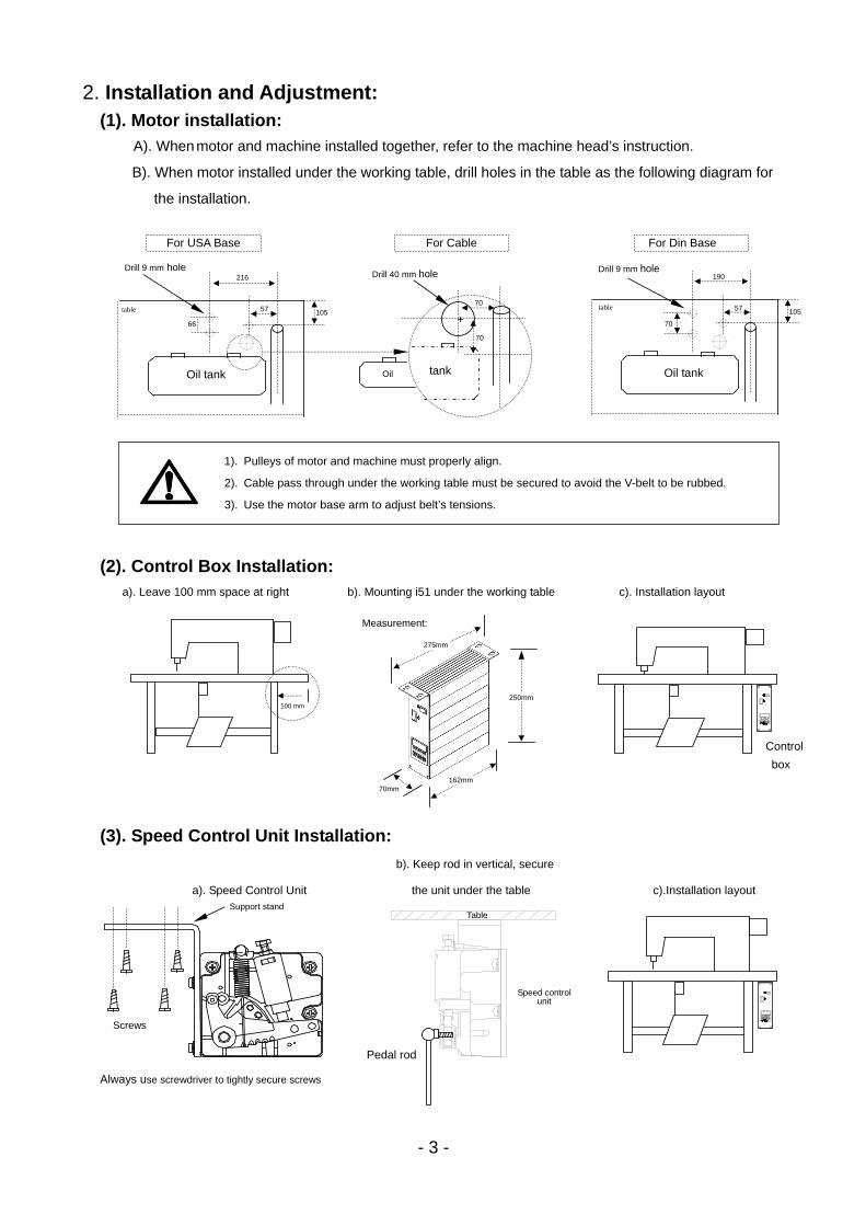
2. Installation and Adjustment: (1). Motor installation:
A). When motor and machine installed together, refer to the machine head’s instruction.
B). When motor installed under the working table, drill holes in the table as the following diagram for
the installation.
(2). Control Box Installation:
(3). Speed Control Unit Installation:
a). Leave 100 mm space at right b). Mounting i51 under the working table c). Installation layout
Control
box
100 mm
For USA Base
57
216
Oil tank
66
105
Drill 9 mm hole
table
For Cable
Drill 40 mm hole
70
tank
70
Oil
57
190
Oil tank
70
105
For Din Base
table
Drill 9 mm hole
1). Pulleys of motor and machine must properly align.
2). Cable pass through under the working table must be secured to avoid the V-belt to be rubbed.
3). Use the motor base arm to adjust belt’s tensions.
b). Keep rod in vertical, secure
a). Speed Control Unit the unit under the table c).Installation layout
Speed control unit
Table
Pedal rod
Screws
Support stand
Always use screwdriver to tightly secure screws
70mm
275mm
162mm
Measurement:
250mm
- 4 -
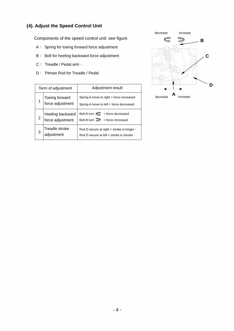
(4). Adjust the Speed Control Unit
Components of the speed control unit: see figure
A: Spring for toeing forward force adjustment
B: Bolt for heeling backward force adjustment
C: Treadle / Pedal arm。
D: Pitman Rod for Treadle / Pedal
B
A
C
D
decrease increase
increase decrease
1
2
3
Term of adjustment
Toeing forward
force adjustment
Heeling backward
force adjustment
Treadle stroke
adjustment
Adjustment result
Spring A move to right = force increased
Spring A move to left = force decreased
Bolt B turn = force decreased
Bolt B turn = force increased
Rod D secure at right = stroke is longer,
Rod D secure at left = stroke is shorter。
5
3. Power Connection and Grounding: (1). Single phase and three phase connection:
Green/yellow wire is the ground wire.
(2). How to connect a 1Φ / 220 V power from a 3 Φ / 380 V power source
1. When a three phase 220 V servo motor used on single phase 200 ~ 240 V power, only connect brown and blue wires. Use insulating tape to wrap up the black wire, in order to prevent the current leakage.
2. Green / Yellow wire must do the grounding.
Caution:If the power source does not have the neutral point, then this 1Φ / 220 V servo motor is not suitable for this connection. Please ask supplier to offer our 3Φ / 380 V servo motor.
R
S
T
N
PEGrounding system G G G
1ψ220V Motor
1ψ220V Motor
1ψ220V Motor
L1 L1 L1
L2
L2
L2
Neutral
Caution: Must have a Neutral point
380 V 380 V 220 V
220 V 220 V
380 V
Single Phase PVC Cable
Brown wire
Blue wire
Green/Yellow wire
Three Phase
Brown
Black
Blue
Green / Yellow To control box
If use on single phase(220 V), don’t connectthe black wire.
6
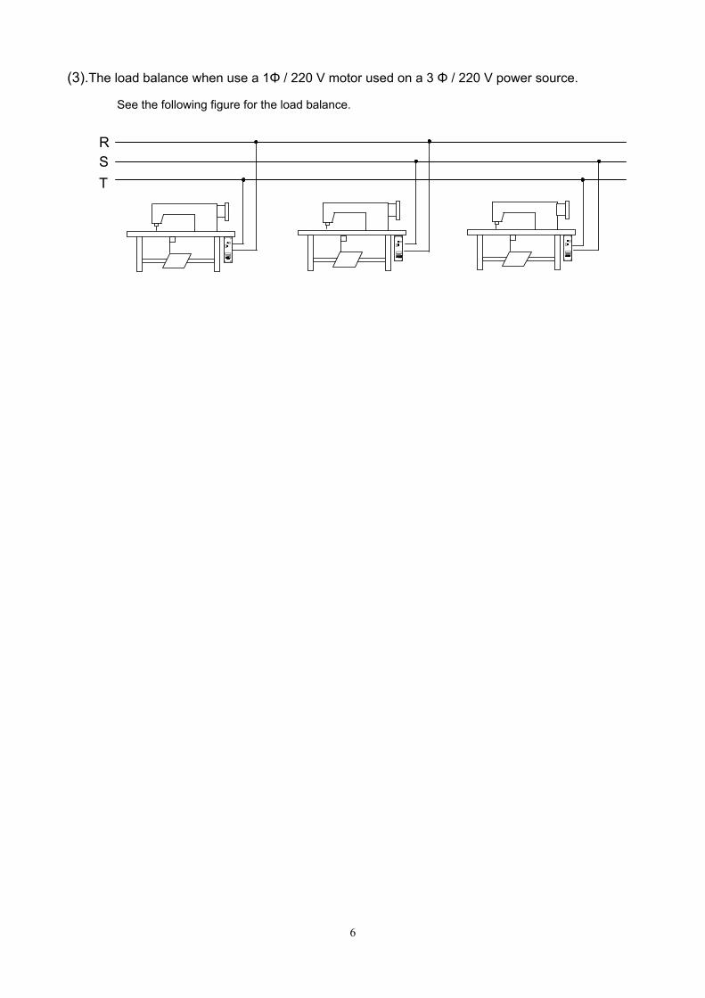
(3).The load balance when use a 1Φ / 220 V motor used on a 3 Φ / 220 V power source.
See the following figure for the load balance.
R S T
- 7 -
4. Diagrams Of Control Box: (1). Front side:
(2). Rear side: Connector Panel (Model sample : i51-4-7W)
STOP
7-segment LCD Setting number of stitches for Lockstitchmachine.
Special function setting for Interlock stitch.machine
AC Power Switch
Callout Parameter
Save Parameter
Start Tacking ON/OFF
End Tacking ON/OFF
Needle UP/Down
Slow Start ON/OFF
Presser foot UP after
trimming
Presser foot UP when
machine stop
Motor Power
Motor Encoder
Speed Control Unit
Foot Switch
Sewing Machine
DC12V Lamp Connector
Automatic Foot Lifter
AC Input
External Synchronizer
M
M
Sewing Machine
- 8 -
5. Programmable 7-segment Display:
(1). How to access the【Normal Mode】area:
Turn on the power and you can access the【Normal Mode】right away.
※ Under this mode, there are Lockstitch and Interlock stitch type displays different.
(2). Key functions in the【Normal Mode】on a lockstitch machine
STOP
Motor rotation
direction icon
Number of Stitches setting (All keys range in 15 stitch)
Presser Foot goes up after trimming
ON / OFF
Soft Start
ON / OFF
Needle UP / Down at
machine stop
Number of stitches display
and other special function display
.
single phase voltage Display showing when use Display showing when use
Lockstitch machine. Interlock machine.
STOP
. STOP
.
End Back-Tacking
ON / OFF
Start Back-Tacking
ON / OFF
Normal sewing /
Bar-tacking /
Constant stitch sewing
Presser Foot goes up when machine stop
ON / OFF
Enter Value area
STOP
- 9 -
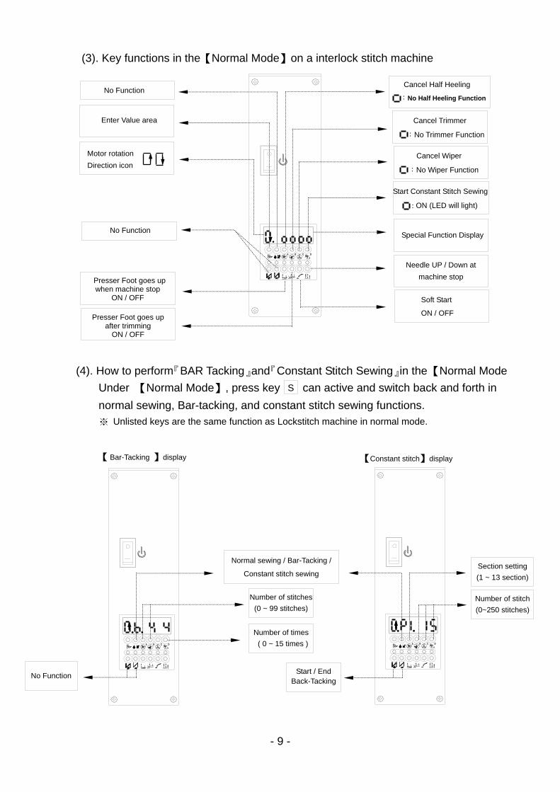
(3). Key functions in the【Normal Mode】on a interlock stitch machine
(4). How to perform『BAR Tacking』and『Constant Stitch Sewing』in the 【Normal Mode
Under 【Normal Mode】, press key can active and switch back and forth in
normal sewing, Bar-tacking, and constant stitch sewing functions.
STOP
. .
STOP
STOP
. .
S
【 Bar-Tacking 】display 【Constant stitch】display
No Function
Number of stitches
(0 ~ 99 stitches)
Number of times
( 0 ~ 15 times )
Section setting
(1 ~ 13 section)
Number of stitch
(0~250 stitches)
Normal sewing / Bar-Tacking /
Constant stitch sewing
Start / End Back-Tacking
※ Unlisted keys are the same function as Lockstitch machine in normal mode.
Motor rotation
Direction icon
No Function
Presser Foot goes up after trimming
ON / OFF
Enter Value area
No Function
Presser Foot goes up when machine stop
ON / OFF
.
Cancel Half Heeling
:No Half Heeling Function
Start Constant Stitch Sewing
: ON (LED will light)
Soft Start
ON / OFF
Needle UP / Down at
machine stop
Special Function Display
Cancel Trimmer
:No Trimmer Function
Cancel Wiper
:No Wiper Function
- 10 -
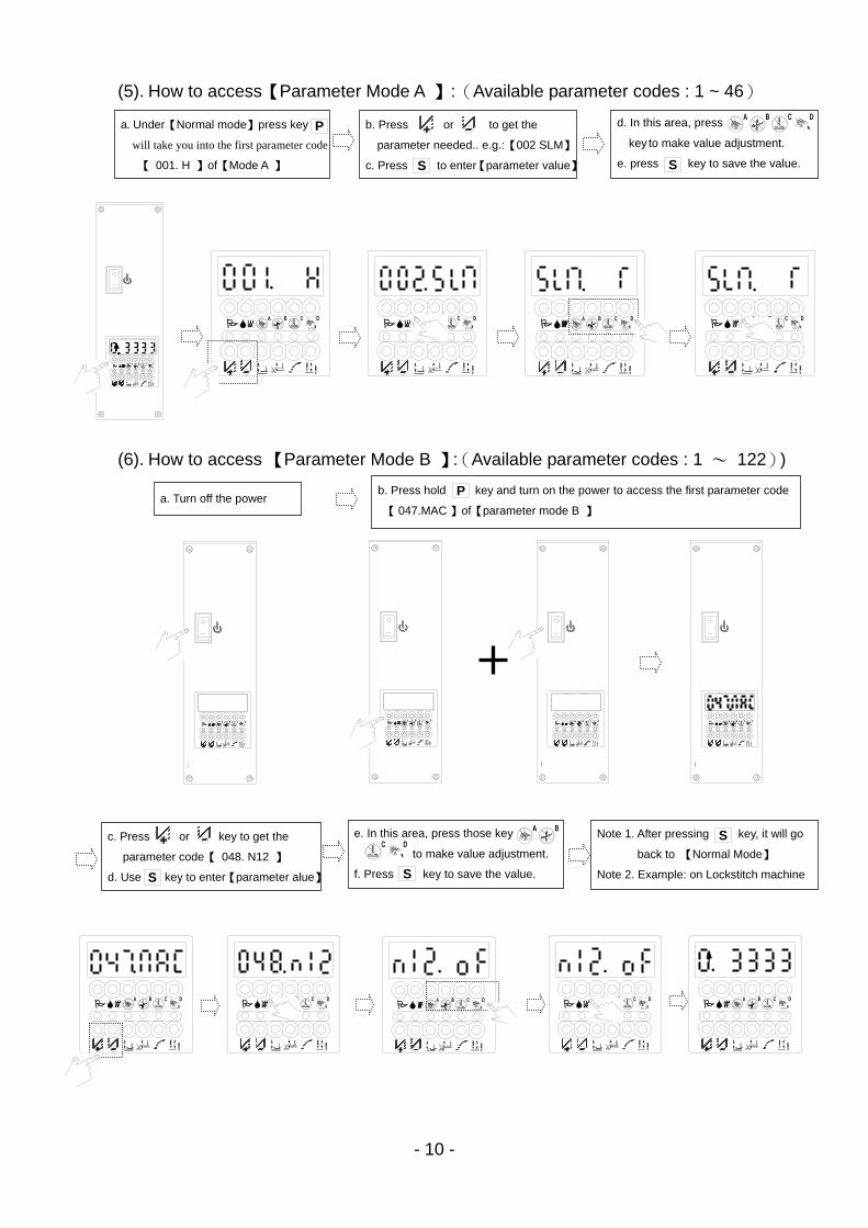
(5). How to access【Parameter Mode A 】:(Available parameter codes : 1 ~ 46)
(6). How to access 【Parameter Mode B 】:(Available parameter codes : 1 ~ 122))
STOPSTOPSTOPSTOP
STOP
.
a. Under【Normal mode】press key will take you into the first parameter code
【 001. H 】of【Mode A 】
P b. Press or to get the
parameter needed.. e.g.:【002 SLM】
c. Press to enter【parameter value】S
d. In this area, press
key to make value adjustment.
e. press key to save the value. S
a. Turn off the power b. Press hold key and turn on the power to access the first parameter code
【 047.MAC 】of【parameter mode B 】
P
c. Press or key to get the parameter code【 048. N12 】
d. Use key to enter【parameter alue】 S
e. In this area, press those key
to make value adjustment.
f. Press key to save the value. S
Note 1. After pressing key, it will go
back to 【Normal Mode】
Note 2. Example: on Lockstitch machine
S
.
STOPSTOPSTOPSTOP
.
. . .
STOPSTOPSTOPSTOPSTOP
. . .
. .
- 11 -
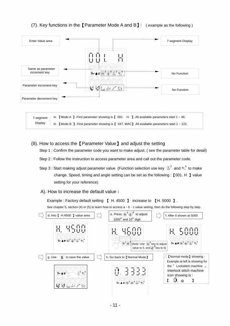
(7). Key functions in the【Parameter Mode A and B】: ( example as the following )
(8). How to access the【Parameter Value】and adjust the setting
Step 1 : Confirm the parameter code you want to make adjust. ( see the parameter table for detail)
Step 2 : Follow the instruction to access parameter area and call out the parameter code.
Step 3 : Start making adjust parameter value. (Function selection use key and to make
change. Speed, timing and angle setting can be set as the following :【001. H 】value
setting for your reference)
A). How to increase the default value :
Example : Factory default setting 【 H. 4500 】 increase to 【H. 5000 】.
See chapter 5, section (4) or (5) to learn how to access a、b、c value setting, then do the following step by step.
STOP
STOP
STOP
STOP
STOP
.
In 【Mode A 】.First parameter showing is【 001. H 】.All available parameters start 1 ~ 46.
In 【Mode B 】.First parameter showing is【 047. MAC】.All available parameters start 1 ~ 122. 7-segment
Display
Parameter decrement key
Parameter increment key
No Function
Same as parameter increment key
Enter Value area 7-segment Display
No Function
d. Into【 H.4500 】value area e. Press to adjust
1000th and 10th digit f. After it shown at 5000
g. Use to save the value S h. Go back to【Normal Mode】 ∴【Normal mode】showing:
Example at left is showing for
the『 Lockstitch machine 』
Interlock stitch machine icon showing is:
【 】 .
.
. .
STOP
.
(Note: Use key to adjust
value to 5, and key to 0)
- 12 -
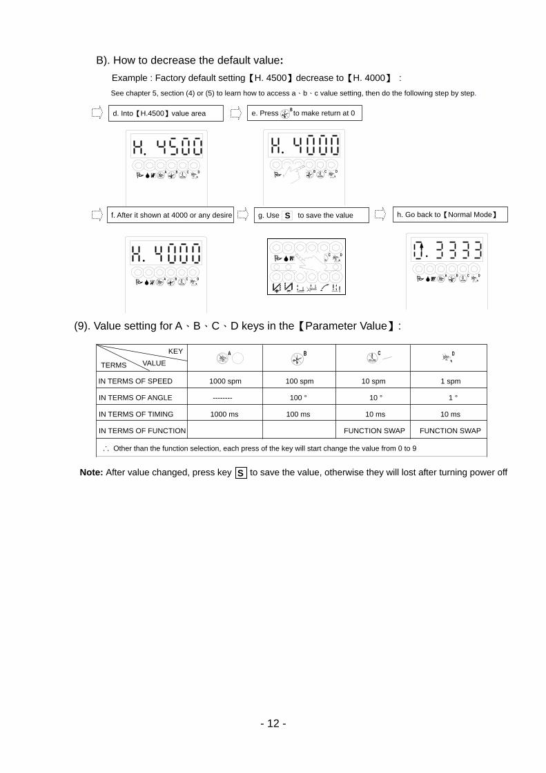
B). How to decrease the default value:
Example : Factory default setting【H. 4500】decrease to【H. 4000】 :
See chapter 5, section (4) or (5) to learn how to access a、b、c value setting, then do the following step by step.
(9). Value setting for A、B、C、D keys in the【Parameter Value】:
STOP
STOP
d. Into【H.4500】value area e. Press to make return at 0
f. After it shown at 4000 or any desire g. Use to save the value S h. Go back to【Normal Mode】
Note: After value changed, press key to save the value, otherwise they will lost after turning power off S
VALUE TERMS
KEY
IN TERMS OF SPEED 1000 spm 100 spm 10 spm 1 spm
IN TERMS OF ANGLE -------- 100 ° 10 ° 1 °
IN TERMS OF TIMING 1000 ms 100 ms 10 ms 10 ms
IN TERMS OF FUNCTION FUNCTION SWAP FUNCTION SWAP
∴ Other than the function selection, each press of the key will start change the value from 0 to 9
.
STOP
.
STOP
.
STOP
.
- 13 -
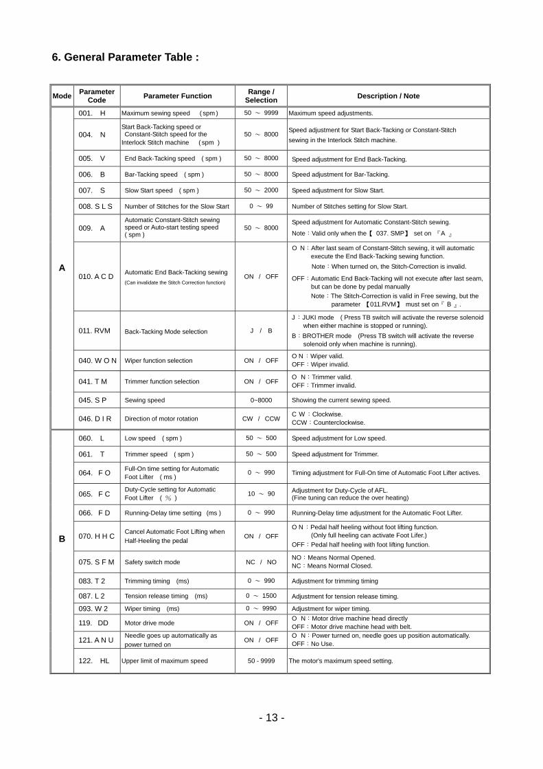
6. General Parameter Table :
Mode Parameter
Code Parameter Function
Range / Selection
Description / Note
001. H Maximum sewing speed ( spm ) 50 ~ 9999 Maximum speed adjustments.
004. N Start Back-Tacking speed or Constant-Stitch speed for the
Interlock Stitch machine ( spm ) 50 ~ 8000
Speed adjustment for Start Back-Tacking or Constant-Stitch
sewing in the Interlock Stitch machine.
005. V End Back-Tacking speed ( spm ) 50 ~ 8000 Speed adjustment for End Back-Tacking.
006. B Bar-Tacking speed ( spm ) 50 ~ 8000 Speed adjustment for Bar-Tacking.
007. S Slow Start speed ( spm ) 50 ~ 2000 Speed adjustment for Slow Start.
008. S L S Number of Stitches for the Slow Start 0 ~ 99 Number of Stitches setting for Slow Start.
009. A Automatic Constant-Stitch sewing speed or Auto-start testing speed ( spm )
50 ~ 8000 Speed adjustment for Automatic Constant-Stitch sewing.
Note:Valid only when the【 037. SMP】 set on 『A 』
010. A C D Automatic End Back-Tacking sewing
(Can invalidate the Stitch Correction function) ON / OFF
O N:After last seam of Constant-Stitch sewing, it will automatic execute the End Back-Tacking sewing function.
Note:When turned on, the Stitch-Correction is invalid.
OFF:Automatic End Back-Tacking will not execute after last seam, but can be done by pedal manually
Note:The Stitch-Correction is valid in Free sewing, but the parameter 【011.RVM】 must set on『 B 』.
011. RVM Back-Tacking Mode selection J / B
J :JUKI mode ( Press TB switch will activate the reverse solenoidwhen either machine is stopped or running).
B:BROTHER mode (Press TB switch will activate the reverse solenoid only when machine is running).
040. W O N Wiper function selection ON / OFF O N :Wiper valid. OFF:Wiper invalid.
041. T M Trimmer function selection ON / OFF O N:Trimmer valid.
OFF:Trimmer invalid.
045. S P Sewing speed 0~8000 Showing the current sewing speed.
A
046. D I R Direction of motor rotation CW / CCW C W :Clockwise. CCW:Counterclockwise.
060. L Low speed ( spm ) 50 ~ 500 Speed adjustment for Low speed.
061. T Trimmer speed ( spm ) 50 ~ 500 Speed adjustment for Trimmer.
064. F O Full-On time setting for Automatic Foot Lifter ( ms )
0 ~ 990 Timing adjustment for Full-On time of Automatic Foot Lifter actives.
065. F C Duty-Cycle setting for Automatic Foot Lifter ( % )
10 ~ 90 Adjustment for Duty-Cycle of AFL. (Fine tuning can reduce the over heating)
066. F D Running-Delay time setting (ms ) 0 ~ 990 Running-Delay time adjustment for the Automatic Foot Lifter.
070. H H C Cancel Automatic Foot Lifting when
Half-Heeling the pedal ON / OFF
O N :Pedal half heeling without foot lifting function. (Only full heeling can activate Foot Lifer.)
OFF:Pedal half heeling with foot lifting function.
075. S F M Safety switch mode NC / NO NO:Means Normal Opened. NC:Means Normal Closed.
083. T 2 Trimming timing (ms) 0 ~ 990 Adjustment for trimming timing
087. L 2 Tension release timing (ms) 0 ~ 1500 Adjustment for tension release timing.
093. W 2 Wiper timing (ms) 0 ~ 9990 Adjustment for wiper timing.
119. DD Motor drive mode ON / OFF O N:Motor drive machine head directly OFF:Motor drive machine head with belt.
B
121. A N U Needle goes up automatically as
power turned on ON / OFF
O N:Power turned on, needle goes up position automatically. OFF:No Use.
122. HL Upper limit of maximum speed 50 - 9999 The motor's maximum speed setting.
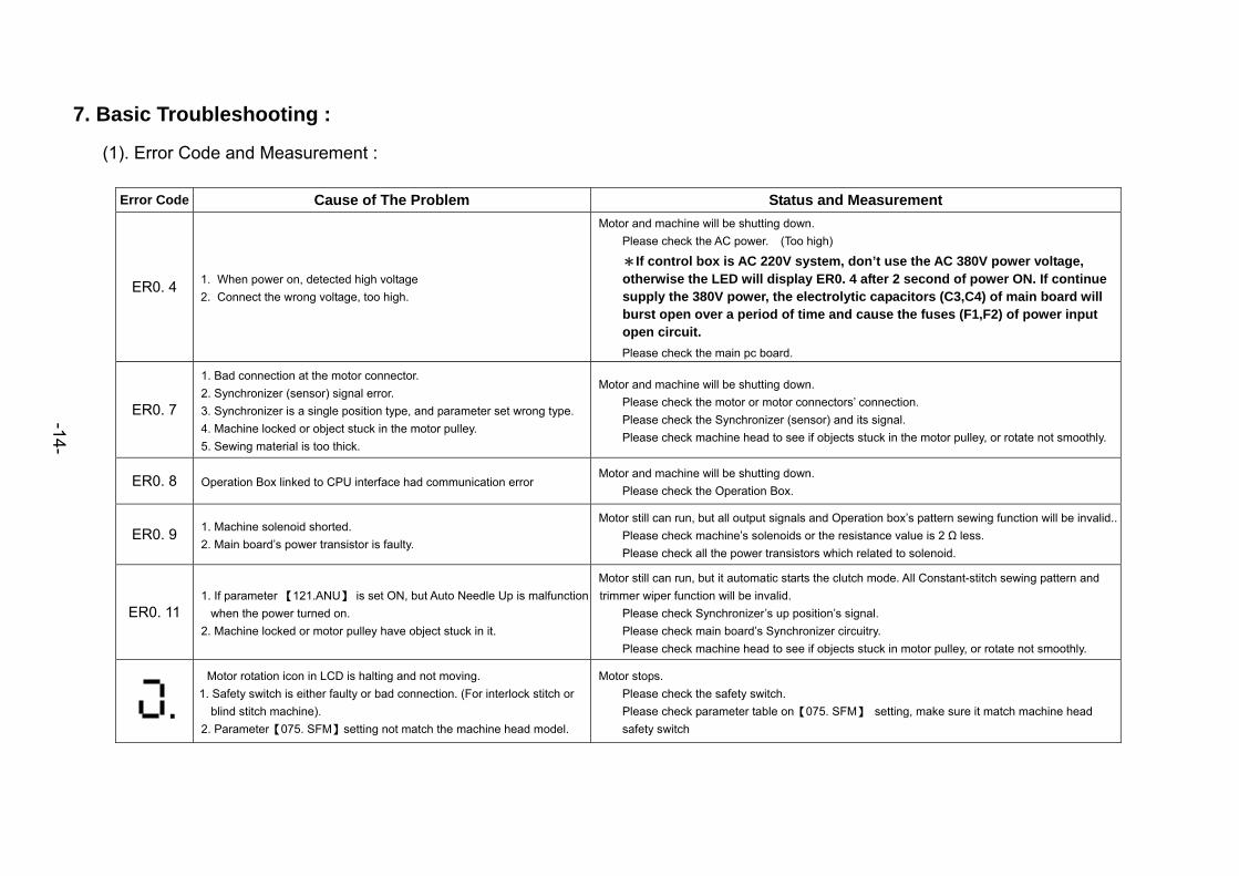
7. Basic Troubleshooting :
(1). Error Code and Measurement :
Error Code Cause of The Problem Status and Measurement
ER0. 4 1. When power on, detected high voltage 2. Connect the wrong voltage, too high.
Motor and machine will be shutting down. Please check the AC power. (Too high)
*If control box is AC 220V system, don’t use the AC 380V power voltage, otherwise the LED will display ER0. 4 after 2 second of power ON. If continue supply the 380V power, the electrolytic capacitors (C3,C4) of main board will burst open over a period of time and cause the fuses (F1,F2) of power input open circuit.
Please check the main pc board.
ER0. 7
1. Bad connection at the motor connector. 2. Synchronizer (sensor) signal error. 3. Synchronizer is a single position type, and parameter set wrong type.
4. Machine locked or object stuck in the motor pulley. 5. Sewing material is too thick.
Motor and machine will be shutting down. Please check the motor or motor connectors’ connection. Please check the Synchronizer (sensor) and its signal. Please check machine head to see if objects stuck in the motor pulley, or rotate not smoothly.
ER0. 8 Operation Box linked to CPU interface had communication error Motor and machine will be shutting down. Please check the Operation Box.
ER0. 9 1. Machine solenoid shorted. 2. Main board’s power transistor is faulty.
Motor still can run, but all output signals and Operation box’s pattern sewing function will be invalid.. Please check machine’s solenoids or the resistance value is 2 Ω less. Please check all the power transistors which related to solenoid.
ER0. 11 1. If parameter 【121.ANU】 is set ON, but Auto Needle Up is malfunction
when the power turned on. 2. Machine locked or motor pulley have object stuck in it.
Motor still can run, but it automatic starts the clutch mode. All Constant-stitch sewing pattern and trimmer wiper function will be invalid.
Please check Synchronizer’s up position’s signal. Please check main board’s Synchronizer circuitry. Please check machine head to see if objects stuck in motor pulley, or rotate not smoothly.
Motor rotation icon in LCD is halting and not moving. 1. Safety switch is either faulty or bad connection. (For interlock stitch or
blind stitch machine). 2. Parameter【075. SFM】setting not match the machine head model.
Motor stops. Please check the safety switch. Please check parameter table on【075. SFM】 setting, make sure it match machine head safety switch
.
-14-
- 15 -
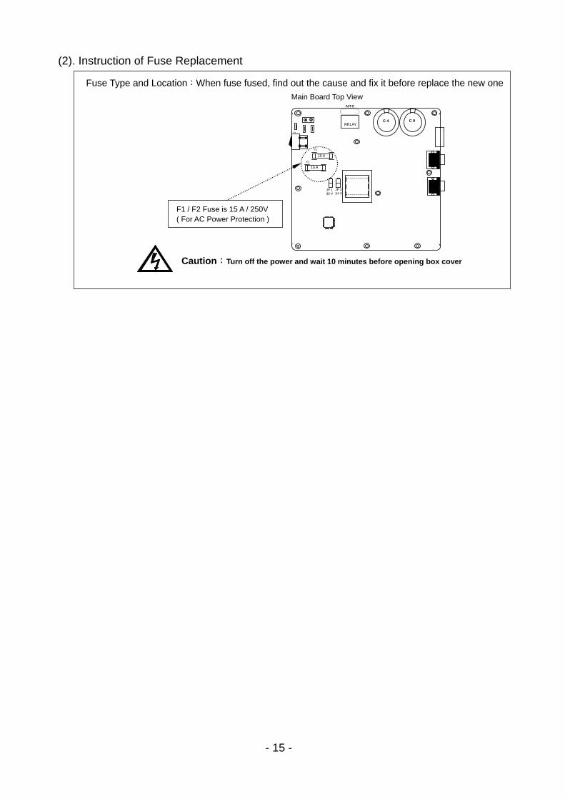
(2). Instruction of Fuse Replacement
Fuse Type and Location:When fuse fused, find out the cause and fix it before replace the new one Main Board Top View
Caution:Turn off the power and wait 10 minutes before opening box cover
F1 / F2 Fuse is 15 A / 250V ( For AC Power Protection )
15 A
15 A
F1
F2
RELAY
S
C 4 C 9
JP 224 V
NTC
JP 130 V
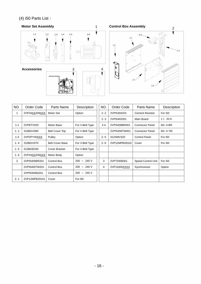
- 16 -
NO. Order Code Parts Name Description NO. Order Code Parts Name Description
1 2VP34XX209XXX Motor Set Option 2- 2 2VPI5304201 Cement Resistor For i50
2- 3 2VPI5402001 Main Board 1∮ 20 A
1-1 2VPBTV020 Motor Base For V-Belt Type 2-4 2VPI5408BR001 Connector Panel i50 -4-BR
1- 2 315BGV080 Belt Cover Top For V-Belt Type 2VPI54087W001 Connector Panel i50 -4-7W
1-3 2VP2PY40XXX Pulley Option 2- 5 312SMV320 Control Panel For i50
1- 4 315BGV070 Belt Cover Base For V-Belt Type 2- 6 2VP12MPB29102 Cover For i50
1- 5 313BGE030 Cover Bracket For V-Belt Type
1- 6 2VP34XX209XXX Motor Body Option
2 2VPI5400BR201 Control Box 200 〜 240 V 3 2VP70306001 Speed Control Unit For i50
2VPI54007W201 Control Box 200 〜 240 V 4 2VP11600XXXX Synchronizer Option
2VPI540066201 Control Box 200 〜 240 V
2- 1 2VP12MPB29101 Cover For i50
(4) i50 Parts List: 1
1-1 1-2 1-3 1-61-4 1-5
Motor Set Assembly
Accessories
Control Box Assembly
2-1
2-2
2-3
2-4
2-5
2-6
3 4
2
- 17 -
8. CONNECTOR DIAGRAM
(1). i 51-4-AS:
M
M
七段顯示器字體與實際數值對照表 :
7-Segment Display Characters Compare Table
數值字體部份 : (Arabic Numerals)
實際數值
Actual 0 1 2 3 4 5 6 7 8 9
七段顯示器
Display
英文字體部份 : (English Alphabet)
英文數字
(Actual) A B C D E F G H I J
七段顯示器
(Display)
英文數字
(Actual) K L M N O P Q R S T
七段顯示器
(Display)
英文數字
(Actual) U V W X Y Z
七段顯示器
(Display)